
FLUORESCENCE MICROSCOPY
Methods for Cell Analysis Course BioVis – Uppsala, 2015
Matyas Molnar and Dirk Pacholsky
1

Information This lecture contains images and information from the following internet homepages http://micro.magnet.fsu.edu/primer/index.html http://www.microscopyu.com/ http://www.olympusmicro.com/primer/lightandcolor/index.html
2

3
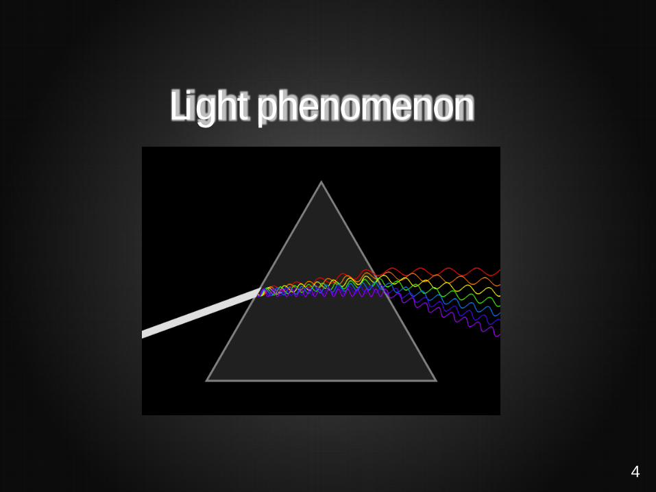
Light phenomenon
4

Light phenomenon
5
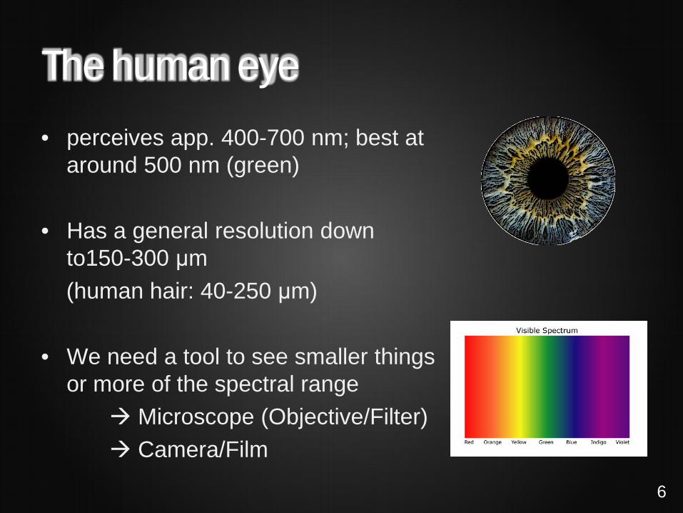
The human eye • perceives app. 400-700 nm; best at
around 500 nm (green)
• Has a general resolution down to150-300 μm
(human hair: 40-250 μm)
• We need a tool to see smaller things or more of the spectral range
Microscope (Objective/Filter) Camera/Film
6

Light phenomenon
• White light comprises of light of different λ (nm,color). • Light travels in vacuum C = 300.000 km/sec • Seems to slows down in denser matter. • Refractive index n = C/v (v= speed in matter) • light is 1.5 x slower at n=1.5 • Light changes direction between different dense materials : shorter λ refract more
than longer λ Optic lenses, effects in sample... shorter wavelength (blue) has higher energy
E
λ
Light photon particle and electromagnetic wave.
7

WHY FLUORESCENCE MICROSCOPY?
8

Microscopical techniques Brightfield - low contrast for thin or transparent
specimen - staining to enhance contrast
needed (histochemical staining) Phase contrast - contrast via optical element (Phase ring) - intracellular structures can be seen - good for cell culture applications - negative: halos around cell bodies - combining with other techniques
is generally poor (e.g. overlay with fluorescent image)
9
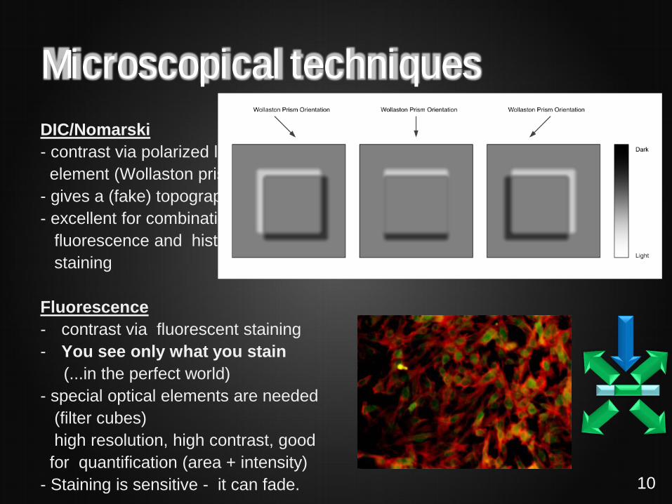
Microscopical techniques DIC/Nomarski - contrast via polarized light & optical element (Wollaston prism) - gives a (fake) topographical view - excellent for combination with fluorescence and histochemical staining Fluorescence - contrast via fluorescent staining - You see only what you stain (...in the perfect world) - special optical elements are needed (filter cubes) high resolution, high contrast, good for quantification (area + intensity) - Staining is sensitive - it can fade.
10

THE MICROSCOPE
11
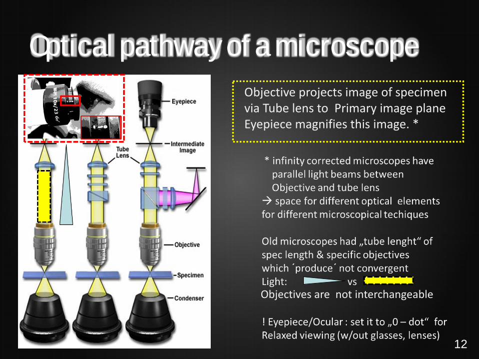
Optical pathway of a microscope
Objectives are not interchangeable
Objective projects image of specimen via Tube lens to Primary image plane Eyepiece magnifies this image. *
12
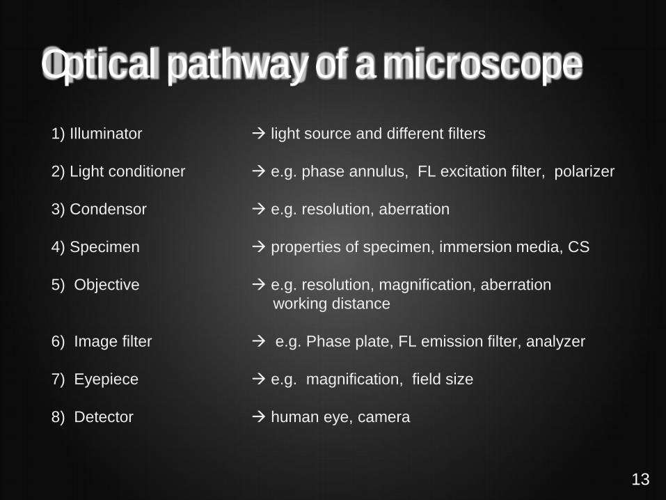
Optical pathway of a microscope 1) Illuminator light source and different filters 2) Light conditioner e.g. phase annulus, FL excitation filter, polarizer 3) Condensor e.g. resolution, aberration 4) Specimen properties of specimen, immersion media, CS 5) Objective e.g. resolution, magnification, aberration working distance 6) Image filter e.g. Phase plate, FL emission filter, analyzer 7) Eyepiece e.g. magnification, field size 8) Detector human eye, camera
13
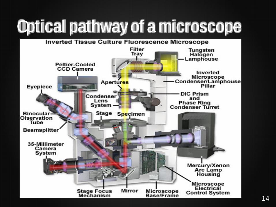
Optical pathway of a microscope
14

The objective or lens
Specification and Identification - Magnification (enlargement) - Numerical aperture (resolution) - Immersion medium (should fit to embedding medium) - corrections (spherical; chromatical) - working distance - tube length (infinity or 160 mm) - coverslip thickness
The heart of a microscope, may contain up to e.g. 12 lenses
15
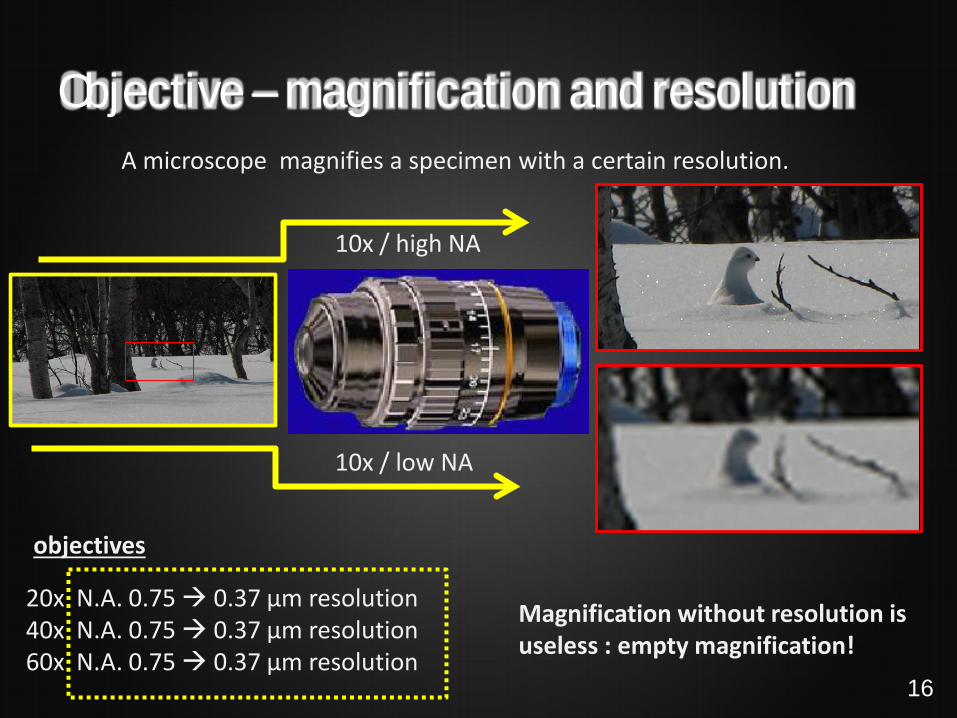
Objective – magnification and resolution A microscope magnifies a specimen with a certain resolution.
10x / high NA
10x / low NA
20x N.A. 0.75 0.37 µm resolution 40x N.A. 0.75 0.37 µm resolution 60x N.A. 0.75 0.37 µm resolution
Magnification without resolution is useless : empty magnification!
objectives
16
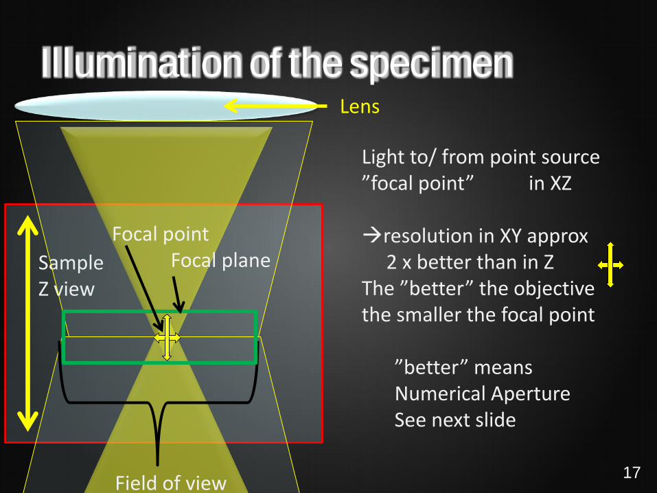
Illumination of the specimen Lens
Light to/ from point source ”focal point” in XZ resolution in XY approx 2 x better than in Z The ”better” the objective the smaller the focal point
”better” means Numerical Aperture See next slide
Sample Z view
Field of view
Focal point Focal plane
17

Illumination of the specimen - resolution
θλsin2n
d =
d: point resolution, the shorter the lenght is better for us [nm] λ: wavelength of light used ([nm], visible light 400-700 nm) n: refractive index (air: 1, water: 1.3, oil: 1.4-1.5) ѳ: the maximum cone of light that can enter or exit the lens nsin(2 ѳ) : numerical aperture (NA)
18
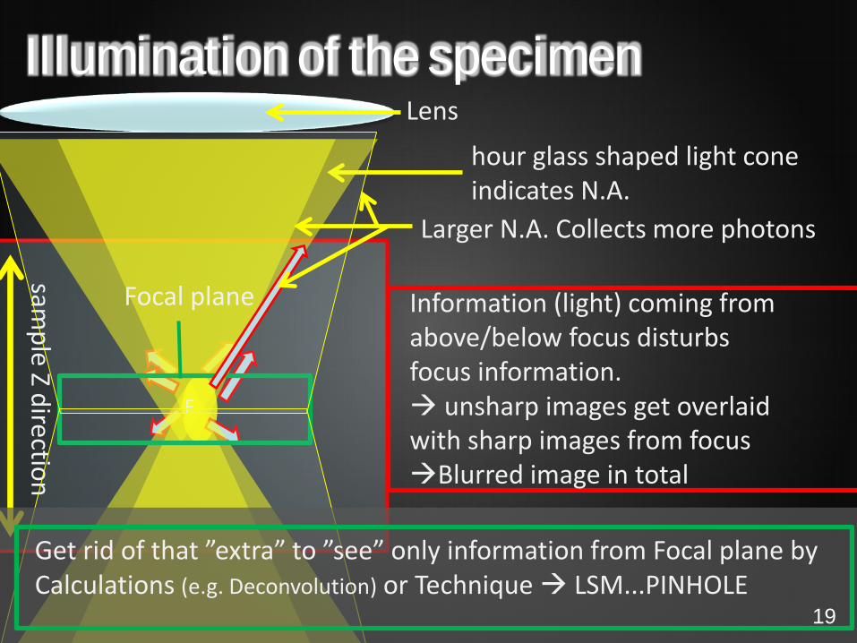
Illumination of the specimen Lens
Information (light) coming from above/below focus disturbs focus information. unsharp images get overlaid with sharp images from focus Blurred image in total
Larger N.A. Collects more photons
hour glass shaped light cone indicates N.A.
sample Z direction
F F
Focal plane
Get rid of that ”extra” to ”see” only information from Focal plane by Calculations (e.g. Deconvolution) or Technique LSM...PINHOLE
19

Objective aberrations
Chromatic aberration: color fringes light in different wavelength travels with different speed (refraction) therefore they won’t meet in one focal point Spherical abberations: unsharp images Different focus of paraxial and peripheral light rays Corrections are possible 20
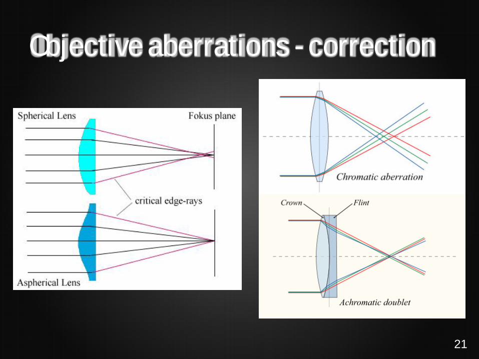
Objective aberrations - correction
21

Objective names • Achromat, Planachromat • chromatical corrected for RB , spherical corrected RB
• Fluar, Fluorite, Planfluorite • chromatical corrected for RGB , spherical corrected RB
• Apochromat, Planapochromat • high N.A. objectives, chromatical corrected for RGB+UV , spherical corrected RGB
• Different brands will have their own (confusing and abbreviated) objective names
• Planapochromates are the objectives to use if resolution and high quality • photomicroscopy is needed.
• Plan”objectives: normal lenses project a curved image. Plan lenses are flat-field
corrected, both the center and the edge of the field is in focus.
• Plan-Neofluar is a fine universal objective for FL-microscopy.
• Use correct coverslip (1.5 = 170µm thickness), immersion for best imaging.
22

Resolution, Airy disk, NA & WD
WD
23

Objective – Resolution and Airy disk Light originally coming from a point and passing through lenses etc. will not be a point again in the image, but rather a dot (1st maxima, AiryDisk) with several side maxima separated by mininima (interference pattern).
The yellow dots shall indicate infinite points, where light originally came from.
The Spreading from Point light source to a Airy disk Image is called Point Spread Function (PSF).
x
z
Airy disk in XZ
PSF gets bigger with mismatch of embedding medium and objective
A point of light will not be a point of light
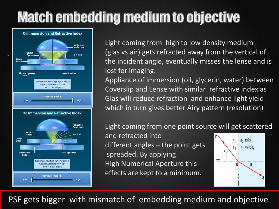
Match embedding medium to objective
.
Light coming from high to low density medium (glas vs air) gets refracted away from the vertical of the incident angle, eventually misses the lense and is lost for imaging. Appliance of immersion (oil, glycerin, water) between Coverslip and Lense with similar refractive index as Glas will reduce refraction and enhance light yield which in turn gives better Airy pattern (resolution) Light coming from one point source will get scattered and refracted into different angles – the point gets spreaded. By applying High Numerical Aperture this effects are kept to a minimum.
PSF gets bigger with mismatch of embedding medium and objective

Practical tips Match objective with correct - Immersion media - Coverslip thickness - Embedding media - Imaging setup - Sample preparation
- Objectives indicate for which immersion media they are made for - Objectives indicate for which coverslip thickness they are made for - Embedding medium has optimally same RI like immersion media - Place the sample as close as possible towards the objective lens - RI of sub-cellular components considerably lower than that of immersion media, and in many cases these RI are uncertain and vary throughout the specimen. Different fixations might destroy antigen to be targeted or might quench fluorescence (of e.g. GFP)
Bad approach
good approach
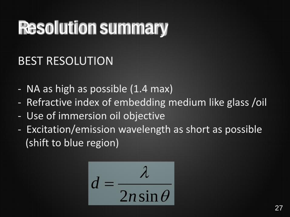
Resolution summary BEST RESOLUTION - NA as high as possible (1.4 max) - Refractive index of embedding medium like glass /oil - Use of immersion oil objective - Excitation/emission wavelength as short as possible (shift to blue region)
θλsin2n
d =27

Applications for fluorescent probes • Proteins using antibodies • Receptors using conjugated ligands • DNA • RNA • Lipids • Lectins to detect proteoglycans and glycolipids • Cytoskeleton • Organelles • “Tracers” for cells and fluids • Viability, proliferation • Ions (Ca2+, ,Mg2+, Zn2+,Na+, K+, Cl-….) • ROS • pH • Membrane potential
28

THE FLUORESCENCE MICROSCOPE
29

Fluorescence Examples of fluorescent probes
Principle of fluorescent microscope
Excitation-Emission filter cube
Principle of fluorescence

The fluorescence microscope
mercury lamp
Mercury (Xenon) lamp spectrum: 300-800 (1300) nm
Filtercube with band-pass-filter to choose wavelength for Excitation and Emission, including a special (dichroic) mirror.
Human eye perceives 400-700 nm Camera/detector will do better
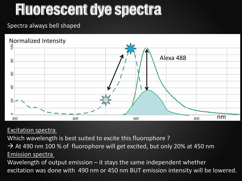
Fluorescent dye spectra Spectra always bell shaped
Excitation spectra Which wavelength is best suited to excite this fluorophore ? At 490 nm 100 % of fluorophore will get excited, but only 20% at 450 nm Emission spectra Wavelength of output emission – it stays the same independent whether excitation was done with 490 nm or 450 nm BUT emission intensity will be lowered.
Alexa 488
Normalized Intensity
nm
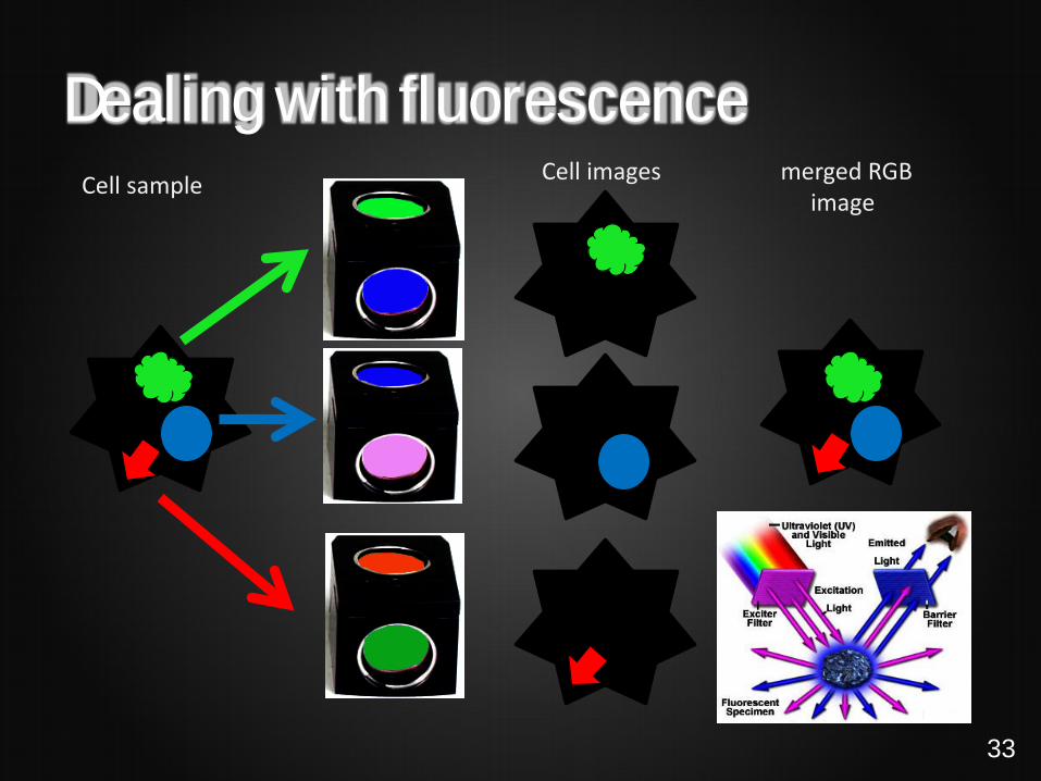
Dealing with fluorescence Cell sample Cell images merged RGB
image
33

Dealing with fluorescence ex
Excitation 350 nm excitates Blue and Green, using BP filter 400-550 collects them both. *Remember: the camera is color blind. You decide with your choice of filter what it will see.
Cell sample
Cell image*
34

Dealing with fluorescence ex
Excitation 350 nm excitates Blue and Green, using BP filter 400-480 collects only the blue. *Remember: the camera is color blind. You decide with your choice of filter what it will see.
Cell sample
Cell image*
35

Dealing with fluorescence ex
Excitation 480 nm excitates Green and Red, using BP filter 510-530 collects only the green. *Remember: the camera is color blind. You decide with your choice of filter what it will see.
Cell sample
Cell image*
36

Combining fluorescent dyes - crosscheck
AbY(1) AbX
X Y X Y
Use quality objectives, correct filter , embedding medium
X
To avoid false positive images in Fluorescence microscopy check for
What´s to be seen in pos/neg control stained unstained
Crossreact AbX with AbY?
AbY(2) AbX
Unspecific backgr. by Ab) ? cell with - w/out target X
X Appropr. fixation? Fixation A) Fixation B)
Crosstalk/ Bleeding through?
ex
Seeing is Believing BUT Is it true?
37
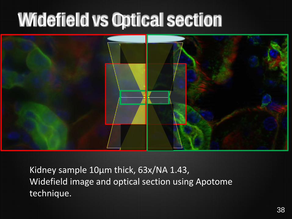
Widefield vs Optical section
Kidney sample 10µm thick, 63x/NA 1.43, Widefield image and optical section using Apotome technique.
38
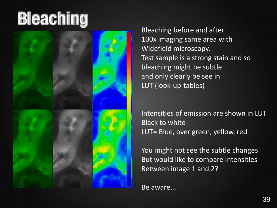
Bleaching Bleaching before and after 100x imaging same area with Widefield microscopy. Test sample is a strong stain and so bleaching might be subtle and only clearly be see in LUT (look-up-tables) Intensities of emission are shown in LUT Black to white LUT= Blue, over green, yellow, red You might not see the subtle changes But would like to compare Intensities Between image 1 and 2? Be aware...
39
IMAGING
40
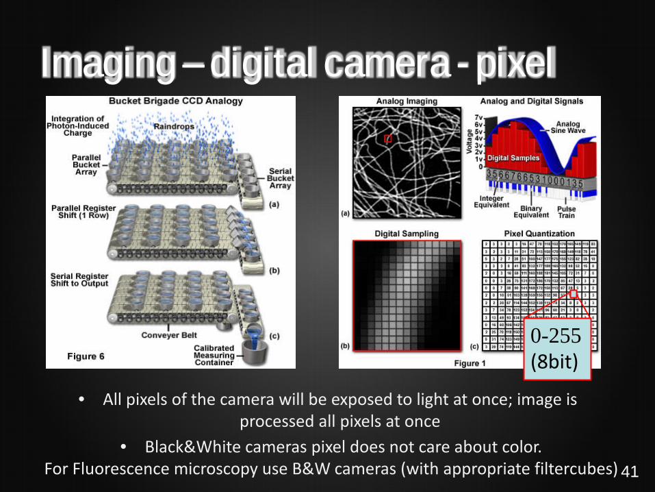
Imaging – digital camera - pixel
• Black&White cameras pixel does not care about color. For Fluorescence microscopy use B&W cameras (with appropriate filtercubes)
0-255 (8bit)
• All pixels of the camera will be exposed to light at once; image is processed all pixels at once
41
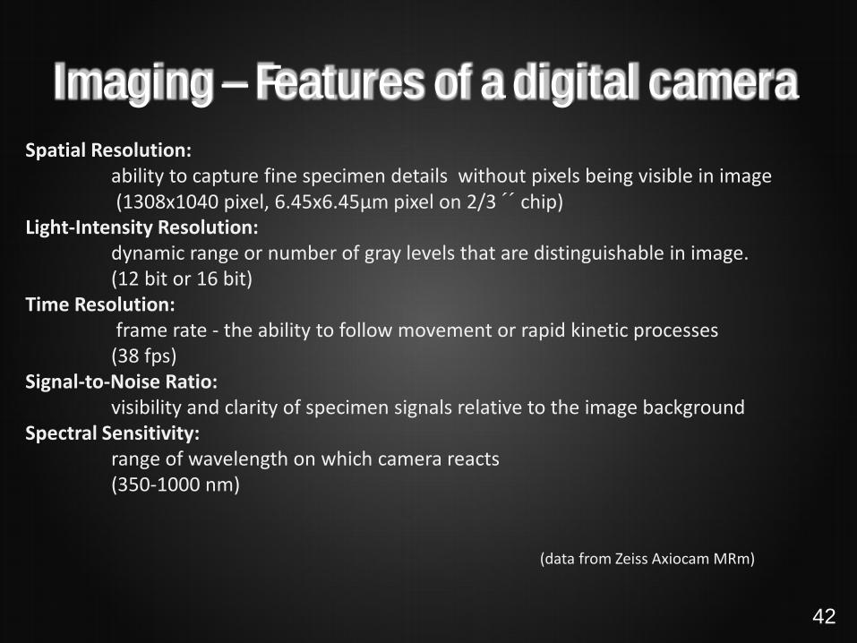
Imaging – Features of a digital camera Spatial Resolution: ability to capture fine specimen details without pixels being visible in image (1308x1040 pixel, 6.45x6.45µm pixel on 2/3 ´´ chip) Light-Intensity Resolution: dynamic range or number of gray levels that are distinguishable in image. (12 bit or 16 bit) Time Resolution: frame rate - the ability to follow movement or rapid kinetic processes (38 fps) Signal-to-Noise Ratio: visibility and clarity of specimen signals relative to the image background Spectral Sensitivity: range of wavelength on which camera reacts (350-1000 nm) (data from Zeiss Axiocam MRm) 42
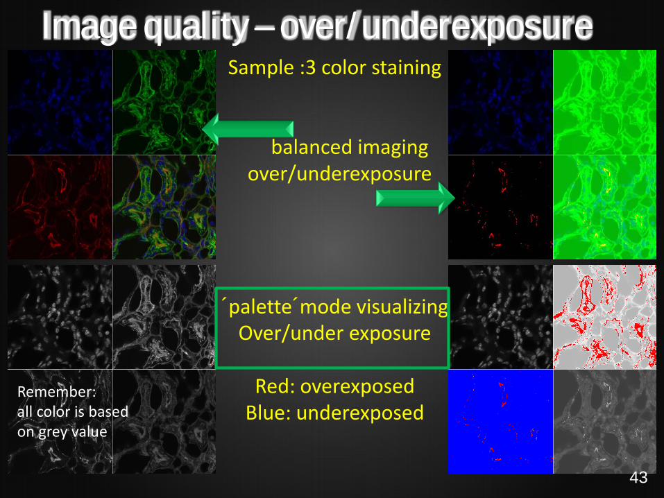
Image quality – over/underexposure Sample :3 color staining
balanced imaging over/underexposure
´palette´mode visualizing Over/under exposure
Red: overexposed
Blue: underexposed Remember: all color is based on grey value
43

Image quality – dynamic range Acquire your image with appropriate grey level (8bit at least) to represent different intensity levels .
12 or 16 (4096 – 65536 grey levels )bit images would also allow you e.g. to enhance features lying in the dark to stretch them into the light...
Inco
min
g ph
oton
s
44

Image quality - resolution
Image should not appear pixelated have enough pixels not enough pixels result in aliasing (jagged edges) and pixel blocking
example for aliasing and pixel blocking
More pixels needed? Larger Chip more expensive camera Smaller pixels size less sensitive, signal to noise ratio decreases
Scientific cameras 6.45x6.45 µm pixel LSM-Systems variable pixel size
45
Imaging – color vs black&white + +/- +/- +/-
+ +
- -
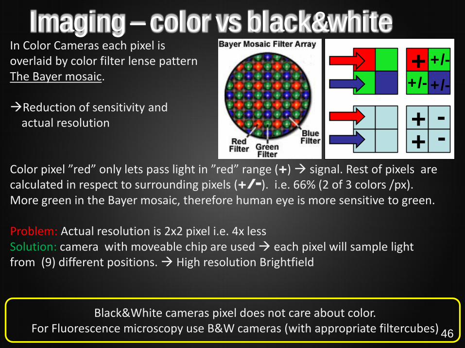
In Color Cameras each pixel is overlaid by color filter lense pattern The Bayer mosaic. Reduction of sensitivity and actual resolution Color pixel ”red” only lets pass light in ”red” range (+) signal. Rest of pixels are calculated in respect to surrounding pixels (+/-). i.e. 66% (2 of 3 colors /px). More green in the Bayer mosaic, therefore human eye is more sensitive to green. Problem: Actual resolution is 2x2 pixel i.e. 4x less Solution: camera with moveable chip are used each pixel will sample light from (9) different positions. High resolution Brightfield
Black&White cameras pixel does not care about color. For Fluorescence microscopy use B&W cameras (with appropriate filtercubes) 46

Publishing photos • Use the highest bit depth as possible, and take care about over/underexposure • Use the highest quality/resolution as possible • Use TIF files • Crop image if neccessary • Use measure bar to show scale • Do not use total magnification, e. g. objective magnification - 60X (which is of
course not 60X magnification but 600X at least)
http://apod.nasa.gov/apod/ap090917.html
Magnification ”1000x”
VS
Measure bar
(20.000 light years)
47

THANKS FOR YOUR ATTENTION!
48


