

ELECTRICAL SYSTEM
COOLING SYSTEM
GROUP INDEX
GENERAL INFORMATION 1
PERIODIC MAINTENANCE 2
ENGINE 3
FUEL SYSTEM 4
5
6
CHASSIS 7
SERVICING INFORMATION 8
� This manual has been prepared on the basis of thelatest specification at the time of publication.I f modif icat ion has been made since then,difference may exist between the content of thismanual and the actual vehicle.
� I llustrations in this manual are used to show thebasic principles of operation and work procedures. They may not represent the actual vehicle exactly in detail.
� COPYRIGHT HYOSUNG MOTORS & MACHINERY INC. 2005.
HYOSUNG MOTORS & MACHINERY INC.
FOREWORD
This manual contains an introductory description on
HYOSUNG and procedures for its
inspection/service and overhaul of its main components.Other information considered as generally known is notincluded.Read GENERAL INFORMATION section to familiarizeyourself with outline of the vehicle and MAINTENANCEand other sections to use as a guide for proper inspec-tion and service.This manual will help you know the vehicle better sothat you can assure your customers of your optimumand quick service.
WARNINGThis manual is intended for those who haveenough knowledge and skills for servicingHYOSUNG vehicles. Without such knowledge andskills, you should not attempt servicing by relyingon this manual only.Instead, please contact your nearby authorizedHYOSUNG motorcycle dealer.

HOW TO USE THIS MANUAL
TO LOCATE WHAT YOU ARELOOKING FOR:1. The text of this manual is divided into sections.2. As the title of these sections is listed on the previous
page as GROUP INDEX, select the section where you are look-ing for.
3. Holding the manual as shown at the right will allow you to find the first page of the section easily.
4. On the first page of each section, its contents are listed. Findthe item and page you need.
COMPONENT PARTS
Example : Front wheel

SYMBOLListed in the table below are the symbols indicating instructions and other information necessary for servicing and meaning associated with them respectively.
Apply THREAD LOCK “1324”.
Apply or use brake fluid.
Measure in voltage range.
Measure in resistance range.
Measure in current range.
Use special tool.
Use engine coolant.
Torque control required.Data beside it indicates specified torque.
Apply oil. Use engine oil unless otherwisespecified.
Apply SUPER GREASE “A”.
Apply SILICONE GREASE.
Apply MOLY PASTE.
Apply BOND “1215”.
Use fork oil.
DEFINITIONSYMBOL DEFINITIONSYMBOL
Apply SUPER GREASE “C”.

NOTEDifference between photographs and actual motorcycles depends on the markets.

GENERAL INFORMATION
INFORMATION LABELS………………………………………………… 1- 1
GENERAL PRECAUTIONS …………………………………………… 1- 1
SERIAL NUMBER LOCATION………………………………………… 1- 3
FUEL, OIL AND ENGINE COOLANT RECOMMENDATIONS …… 1- 4
BREAK-IN PROCEDURES……………………………………………… 1- 6
CYLINDER CLASSIFICATION………………………………………… 1- 6
EXTERIOR ILLUSTRATION …………………………………………… 1- 7
SPECIFICATIONS ………………………………………………………… 1- 8
CONTENTS
1

1-1 GENERAL INFORMATION
Please note, however, that the warning and cautions contained in this manual cannot possibly cover all potential hazards relating to the servicing, or lack of servicing, of the motorcycle. In addition to the WARNING and CAUTION stated, you must use good judgement and basic mechanical safety principles. If you are unsure about how to perform aparticular service operation, ask a more experienced mechanic for advice.
GENERAL PRECAUTIONS
WARNING / CAUTION / NOTE
Please read this manual and follow its instructions carefully. To emphasize special information, the symbol and the words WARNING, CAUTION and NOTE have special meanings. Pay special attention to the messages highlighted by these signal words.
CAUTIONIndicates a potential hazard that could result in vehicle damage.
WARNINGIndicates a potential hazard that could result in death or injury.
NOTEIndicates special information to make maintenance easier or instructions cleaner.
WARNING� Proper service and repair procedures are important for the safety of the service machanic and the safe-
ty and reliability of the vehicle.�When 2 or more persons work together, pay attention to the safety of each other.�When it is necessary to run the engine indoors, make sure that exhaust gas is forced outdoors.� When working with toxic or flammable materials, make sure that the area you work in is well-ventilat-
ed and that you follow all off the material manufacturer’s instructions.� Never use gasoline as a cleaning solvent.� To avoid getting burned, do not touch the engine, engine oil, exhaust system or radiator during or
for a while after engine operation.� After servicing fuel, oil, engine coolant, exhaust or brake systems, check all lines and fittings related
to the system for leaks.

GENERAL INFORMATION 1-2
WARNING� If parts replacement is necessary, replace the parts with HYOSUNG Genuine Parts or their equivalent.�When removing parts that are to be reused, keep them arranged in an orderly manner so that they may
be reinstalled in the proper order and orientation.� Be sure to use special tools when instructed.� Make sure that all parts used in reassembly are clean, and also lubricated when specified.�When use of a certain type of lubricant, bond, or sealant is specified, be sure to use the specified type.�When removing the battery, disconnect the negative cable first and then positive cable. When
reconnecting the battery, connect the positive cable first and then negative cable, and replace the terminalcover on the positive terminal.
� When performing service to electrical parts, if the service procedures do not require use ofbattery power, diconnect the negative cable at the battery.
� Tighten cylinder head and case bolts and nuts, beginning with larger diameter and ending with small-er diameter, from inside to outside diagonally, to the specified tightening torque.
� Whenever you remove oil seals, gaskets, packing, O-rings, locking washers, cotter pins, circlips,and certain other parts as specified, be sure to replace them with new ones. Also, before installingthese new parts, be sure to remove any material left over from the mating surfaces.
� Never reuse a circlip. When installing a new circlip, take care not to expand the end gap largerthan required to slip the circlip over the shaft. After installing a circlip, always ensure that it is com-pletely seated in its groove and securely fitted.
� Do not use self-locking nuts a few times over.� Use a torque wrench to tighten fasteners to the torque values when specified. Wipe off grease or
oil if a thread is smeared with them.� After reassembly, check parts for tightness and operation.
WARNING� To protect environment, do not unlawfully dispose of used motor oil and other fluids: batteries, and tires.� To protect Earth’s natural resouces, properly dispose of used vehicles and parts.

SERIAL NUMBER LOCATION
The frame serial number or V.I.N. (Vehicle Identification Number) is stamped on the steering head tube. The engine serial number is located on the left downside of crankcase assembly.These numbers are required especially for registering the machine and ordering spare parts.
◉ FRAME SERIAL NUMBER
◉ ENGINE SERIAL NUMBER
1-3 GENERAL INFORMATION

◉ FRONT FORK OIL▣ Use fork oil : TELLUS #32
◉ BRAKE FLUID▣ Specification and classification (Front brake) : DOT3 or DOT4
(Rear brake) : DOT4
Grade
Over SL
10W/40
Classification system
API
SAE
※ If an SAE 10W/40 motor oil is not available, select analternative according to the following chart.
Use a premium quality 4-stroke motor oil to ensure longer service life of your motorcycle.
FUEL, OIL AND ENGINE COOLANT RECOMMENDATIONS
◉ FUELGasoline used should be graded 91 octane (Research Method) or higher. An unleaded gasoline type isrecommended.
◉ ENGINE OIL▣ ENGINE OIL SPECIFICATION
WARNING� Don’t mix the unrecommended oil. It could damage the engine.� When refilling the oil tank, don’t allow the dust to get inside.� Mop the oil spilt.� Don’t put the patch on the cap. It could disturb the oil to be provided and damage the engine.
WARNINGSince the brake system of this motorcycle is filled with a glycol-based brake fluid by the manufacturer, do not use or mix different types of fluid such as silicone-based and petroleum-based fluid for refilling the sys-tem, otherwise serious damage will result.Do not use any brake fluid taken from old or used or unsealed containers.Never re-use brake fluid left over from a previous servicing, which has been stored for a long period.
GENERAL INFORMATION 1-4

1-5 GENERAL INFORMATION
◉ ENGINE COOLANTUse an anti-freeze/engine coolant compatible with an aluminum radiator, mixed with distilled water only.
▣ WATER FOR MIXINGUse distilled water only. Water other than distilled water can corrode and clog the aluminum radiator.
▣ ANTI-FREEZE/ENGINE COOLANTThe engine coolant perform as a corrosion and rust inhibitor as well as anti-freeze. Therefore, the engine coolant
should be used at all times even though the atmospheric temperature in your area does not go down to freezing point.
Hyosung recommends the use of HYOSUNG COOLANT anti-freeze/engine coolant. If this is not available, use an
equivalent which is compatible with an aluminum radiator.
▣ LIQUID AMOUNT OF WATER/ENGINE COOLANTFor engine coolant mixture information, refer to cooling system section, page 5-1
CAUTIONMixture of anti-freeze/engine coolant should be limited to 60%. Mixing beyond it would reduce itsefficiency. If the anti-freeze/engine coolant mixing ratio is below 50%, rust inhabiting performanceis greatly reduced. Be sure to mix it above 50% even though the atmospheric temperature does notgo down to the freezing point.

CYLINDER CLASSIFICATION
The engine of is composed of the two cylinder, is classified into the front cylinder and rear cylin-der as basis of the motorcycle ahead.
● Upon reaching an odometer reading of 1,600 km you can subject the motorcycle to full throttle operation.● Do not maintain constant engine speed for an extended period during any portion of the break-in. Try to vary the
throttle position.
BREAK-IN PROCEDURES
During manufacture only the best possible materials are used and all machined parts are finished to a very high standard but it is still necessary to allow the moving parts to “BREAK-IN”before subjecting the engine to maximumstresses. The future performance and reliability of the engine depends on the care and restraint exercised during itsearly life. The general rules are as follows :● Keep to these break-in procedures :
Initial 800km
Up to 1,600km
Less than 1/2 throttle
Less than 3/4 throttle
Rear cylinder
Front cylinder
⇒FRONT
GENERAL INFORMATION 1-6
1-7 GENERAL INFORMATION
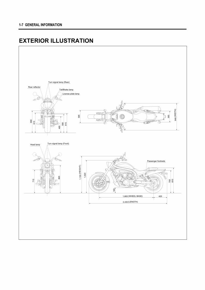
EXTERIOR ILLUSTRATION

2,430 mm (95.7 in)
840 mm (33.1 in)
1,155 mm (45.5 in)
1,665 mm (65.6 in)
160 mm (6.3 in)
220 kg (485 lbs)
Overall length
Overall width
Overall height
Wheelbase
Ground clearance
Mass
I T E M
I T E M
I T E M
Four-stroke, DOHC, Liquid-cooled
V-2 cylinder
81.5 mm (3.21 in)
62.0 mm (2.44 in)
647 ㎤ (39.5 in3 )
BDSR39 TYPE (DOUBLE)
Electric starter
Wet sump
Type
Number of cylinder
Bore
Stroke
Piston displacement
Carburetor
Starter system
Lubrication system
Wet multi-plate type
5-speed constant mesh
1-down, 4-up
2.79
2.46
1.78
1.38
1.13
0.96
Poly chain belt
Clutch
Transmission
Gearshift pattern
Final reduction
Gear ratio, 1st
2nd
3rd
4th
5th
Drive belt
GENERAL INFORMATION 1-8
SPECIFICATIONS
◉ DIMENSIONS AND DRY MASS
◉ ENGINE
◉ TRANSMISSION
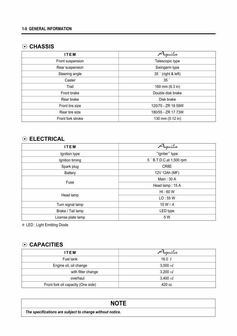
Telescopic type
Swingarm type
35°(right & left)
35°
160 mm (6.3 in)
Double disk brake
Disk brake
120/70 - ZR 18 59W
180/55 - ZR 17 73W
130 mm (5.12 in)
Front suspension
Rear suspension
Steering angle
Caster
Trail
Front brake
Rear brake
Front tire size
Rear tire size
Front fork stroke
I T E M
I T E M
I T E M
“Igniter”type
5°B.T.D.C.at 1,500 rpm
CR8E
12V 12Ah (MF)
Main : 30 A
Head lamp : 15 A
HI : 60 W
LO : 55 W
10 W×4
LED type
5 W
Ignition type
Ignition timing
Spark plug
Battery
Turn signal lamp
Brake / Tail lamp
License plate lamp
※ LED : Light Emitting Diode
Fuel tank
Engine oil, oil change
with filter change
overhaul
Front fork oil capacity (One side)
16.0 ℓ
3,000 ㎖
3,200 ㎖
3,400 ㎖
420 cc
NOTEThe specifications are subject to change without notice.
1-9 GENERAL INFORMATION
◉ CHASSIS
◉ ELECTRICAL
◉ CAPACITIES
Fuse
Head lamp

PERIODIC MAINTENANCE SCHEDULE ………………………… 2- 1
PERIODIC MAINTENANCE CHART…………………………………… 2- 1
LUBRICATION POINTS ………………………………………………… 2- 3
MAINTENANCE PROCEDURES …………………………………… 2- 4
VALVE CLEARANCE …………………………………………………… 2- 4
SPARK PLUG …………………………………………………………… 2- 6
EXHAUST PIPE BOLTS AND MUFFLER MOUNTING BOLTS……… 2- 7
AIR CLEANER …………………………………………………………… 2- 8
CARBURETOR …………………………………………………………… 2- 9
FUEL HOSE ……………………………………………………………… 2-10
CLUTCH …………………………………………………………………… 2-10
ENGINE OIL ……………………………………………………………… 2-12
ENGINE OIL FILTER …………………………………………………… 2-14
DRIVE BELT ……………………………………………………………… 2-15
BRAKE SYSTEM ………………………………………………………… 2-17
STEERING ………………………………………………………………… 2-21
FRONT FORK …………………………………………………………… 2-21
REAR SUSPENSION …………………………………………………… 2-21
TIRE………………………………………………………………………… 2-22
CHASSIS BOLTS AND NUTS ………………………………………… 2-22
ENGINE COOLANT ……………………………………………………… 2-23
RADIATOR HOSE………………………………………………………… 2-25
COMPRESSION PRESSURE…………………………………………… 2-26
OIL PRESSURE ………………………………………………………… 2-27
CONTENTS
2
2 PERIODIC MAINTENANCE

2-1 PERIODIC MAINTENANCE
ItemInitial 1,000 km Every 6,000 km Every 12,000 km page
Interval
Air cleaner elementExhaust pipe bolts andmuffler mounting boltsValve clearance adjustCylinder head boltCylinder head & CylinderSpark plug
Fuel hose
Engine oil filterEngine oilThrottle cableIdle speedClutchEngine coolant
Radiator hoses
Tighten
InspectTighten
─
CleanInspect
ReplaceReplaceInspectInspectInspect
─
─
─
─
Remove carbonReplace
─
─
─
─
─
─
─
2-8
2-7
2-43-503-212-6
2-10
2-142-122-92-92-102-23
2-25
Replace every 4 years
Replace every 2 years
Replace every 4 years
ItemInitial 1,000 km Every 6,000 km Every 12,000 km page
Interval
Drive beltBrake
Brake hoses
Brake fluid
TiresSteeringFront forksRear suspensionChassis bolts and nuts
InspectInspect
Inspect
InspectInspect
─
─
Tighten
InspectInspect
Inspect
InspectInspectInspectInspectTighten
─
─
─
─
─
─
─
─
Inspect every 1,000km
Replace every 4 years
Replace every 2 years
▣ CHASSIS
2-152-17
2-17
2-17
2-222-212-212-212-22
PERIODIC MAINTENANCE SCHEDULEThe chart below lists the recommended intervals for all the required periodic service work necessary to keep the motorcycle operating at peak performance and economy.
Tighten
InspectTighten
─
CleanInspect
ReplaceReplaceInspectInspectInspect
Inspect
Clean every 3,000 km Replace every 12,000 km
CAUTIONUsing poor quality replacement parts can cause your motorcycle to wear more quickly and shorten its useful life.Use only genuine Hyoung replacement parts or their equivalent.
CAUTIONMore frequent servicing should be performed on motorcycles that are used under severe conditions.
PERIODIC MAINTENANCE CHART▣ ENGINE

PERIODIC MAINTENANCE 2-2
◆ USE OF FUEL TANK STAY● Place the motorcycle on the side stand.● Remove the seat by removing the seat mounting bolt
① on the seat tail cover.
▣ FUEL TANK STAYhas the “fuel tank stay” under the seat.
Use the “fuel tank stay” to inspect the engine or theother parts easily.
● Remove the fuel tank mounting bolt ②.● Take the fuel tank stay ③ off the tray upper the bat-
tery.
● Lift the rear end of the fuel tank and prop it up asshown illustration.Insert the crank end of the fuel tank stay ③ into thehole of the fuel tank and frame.
①
③
③
③
②

2-3 PERIODIC MAINTENANCE
LUBRICATION POINTProper lubrication is important for smooth operation and long life of each working part of the motorcycle.Major lubrication points are indicated below.
① Clutch lever holder and clutch cable② Passenger footrests pivot ③ Side stand pivot and spring hook ④ Footrests pivot
⑤ Speedometer gear box ⑥ Front brake lever holder ⑦ Throttle cable⑧ Rear brake pedal pivot
O - Motor oil, G - Grease
NOTE� Before lubricating each part, clean off any rusty spots and wipe off any grease, oil, dirt or grime.� Lubricate exposed parts which are subject to rust, with either motor oil or grease whenever the motor-
cycle has been operated under wet or rainy condition.
PERIODIC MAINTENANCE 2-4
MAINTENANCE PROCEDURES
This section describes the service procedure for each section of the periodic maintenance.
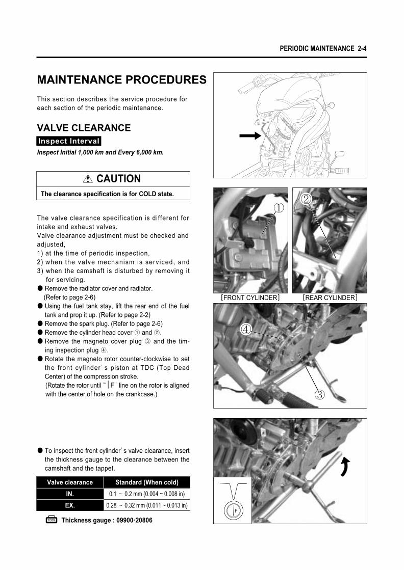
VALVE CLEARANCE
The valve clearance specification is different for intake and exhaust valves.Valve clearance adjustment must be checked and adjusted, 1) at the time of periodic inspection, 2) when the valve mechanism is serv iced, and3) when the camshaft is disturbed by removing it
for servicing.● Remove the radiator cover and radiator.
(Refer to page 2-6)● Using the fuel tank stay, lift the rear end of the fuel
tank and prop it up. (Refer to page 2-2)● Remove the spark plug. (Refer to page 2-6)● Remove the cylinder head cover ① and ②.● Remove the magneto cover plug ③ and the tim-
ing inspection plug ④.● Rotate the magneto rotor counter-clockwise to set
the front cyl inder’s piston at TDC (Top DeadCenter) of the compression stroke.(Rotate the rotor until “|F”line on the rotor is alignedwith the center of hole on the crankcase.)
0.1 � 0.2 mm (0.004 ~ 0.008 in)
0.28 � 0.32 mm (0.011 ~ 0.013 in)
IN.
EX.
Standard (When cold)Valve clearance
Thickness gauge : 09900-20806
● To inspect the front cylinder’s valve clearance, insertthe thickness gauge to the clearance between thecamshaft and the tappet.
Inspect Interval
Inspect Initial 1,000 km and Every 6,000 km.
CAUTIONThe clearance specification is for COLD state.
[REAR CYLINDER][FRONT CYLINDER]
③
②①
④

● If the clearance is out of specification, first remove thecam chain tensioner, camshaft housing, camshaft.To install the tappet shim at original position, recordthe shim NO. and clearance to present by “A”, “B”,
“C”, “D”mark on the cylinder head.
Select the tappet that agree with tappet clearance(vertical line) and shim NO.(horizontal line) as refer to thetappet shim selection chart. (Refer to page 8-31∙32)
Adjust valve timing, install the camshaft housing andthe tensioner.After the crankshaft rotate about 10 times, measurethe valve clearance.If the clearance be not correct, adjust the standardclearance as the same manner above.● In case of valve adjustment which is not the tappet
shim selection chart, please follow instructions ofexample in the below.For example, the intake clearance is 0.4 and the shim
is 170 (1.70 mm), select 195 (1.95 mm) of the shimwhich 170 (1.70 mm) of the shim add up the excessclearance 0.25 mm when adjust with the standard0.15 as the intake standard clearance 0.1�0.2 mm.
CAUTION� Valve clearance should be checked when the
engine is cold.� If you don’t rotate the crankshaft about 10
times before measuring the valve clearance,there is no meaning of valve clearance.
● Rotate the magneto rotor to set the rear cylinder’spiston at TDC(Top Dead Center) of the compressionstroke.(Rotate the rotor 285�counter-clockwise from the
“|F”line, and until the “|R”line on the rotor isaligned with the center of hole on the crankcase.)
● Inspect the rear cylinder’s valve clearance with thesame manner of the front cylinder.
2-5 PERIODIC MAINTENANCE
B
D
A
C

PERIODIC MAINTENANCE 2-6
TYPE SPARK PLUG SPECIFICATION
CR7E
CR8E
CR9E
Hot type
Standard type
Cold type
● Remove the four radiator mounting bolts.
● Remove the four radiator cover mounting bolts.
SPARK PLUG
Inspect Interval
Clean Initial 1,000 km and Every 6,000 km, Replace Every 12,000 km.
● Disconnect the spark plug caps.● Remove the spark plugs.
CAUTION●● Be careful not to damage the radiator fins.●● Do not extract the radiator hose.
● Remove the seat and fuel tank mounting bolts. (Refer to page 2-2)
● Using the fuel tank stay, lift the rear end of the fueltank and prop it up.
WARNINGThe hot radiator and the hot engine can burnyou. Wait until the radiator and the engine arecool enough to touch.

Check to see the worn or burnt condition of the elec-trodes.If it is extremly worn or burnt, replace the plug.And also replace the plug if it has a broken insula-tor, damaged thread, etc.● Install the spark plug, and then tighten it to speci-
fied torque.
Spark plug : 11 N∙m (1.1 kg∙m)
EXHAUST PIPE BOLTS ANDMUFFLER MOUNTING BOLTS
● Tighten the exhaust pipe bolts ①, and muff lermounting bolts ② to the specified torque.
Exhaust pipe bolt : 18~28 N∙m (1.8~2.8 kg∙m)
Muffler mounting bolt : 18~28 N∙m (1.8~2.8 kg∙m)
Inspect Interval
Tighten Initial 1,000 km and Every 6,000 km.
2-7 PERIODIC MAINTENANCE
Remove the carbon deposit with wire or pin and adjustthe spark plug gap to 0.7�0.8 mm (0.028~0.032 in),measuring with a thickness gauge.
0.7�0.8 mm (0.028~0.032 in)Spark plug gap
Thickness gauge : 09900-20806
[ Rear Cylinder ]
[ Front Cylinder ]
0.7 ~ 0.8 mm(0.028 ~ 0.032 in)
①
①
②

PERIODIC MAINTENANCE 2-8
①
②
③
Clean the air cleaner element for the following :● When the air cleaner element clean with the air gun,
necessarily blow at the inside by compressed air.● Carefully examine the air cleaner element for tears during
cleaning. Replace it with a new one if it is torn.● Assemble the element completely or damage severely
the engine.● Be careful not to allow water to go inside the air clea-
ner element.
CAUTIONMore frequent servicing may be performed on mo-torcycles that are used under severe condi-tions, also clean the air cleaner element whenreplacing the oil to prevent damage of the engine.
AIR CLEANER
● Remove the seat.● The air cleaner is located under the fuel tank.
Remove the fuel tank.● Remove the four air cleaner inlet guide mounting
screws ①.
● Pull up the air cleaner inlet guide ② and the aircleaner element ③.
Inspect Interval
Clean Every 3,000 km,Replace Every 12,000 km.

● Connect an engine tachometer to the high ten-sion cord.Start up the engine and set its speed at any-where 1,300 and 1,500 rpm by turning throttle stopscrew �.
▣ THROTTLE CABLE PLAYThis motorcycle has a twin throttle cable system. Cable� is for throttle cable and cable � is for returning cable.There should be 0.5~1.0mm play on the throttle cable.To adjust the throttle cable play.● Loosen the lock nut ① of the returning cable � and
fully turn in the adjuster ②.
● Loosen the lock nut ③ of the throttle cable �.
● Turn the adjuster ④ in or out until the throttle cableplay is between 0.5 ~ 1.0mm (0.02 ~ 0.04 in).
● Tighten the lock nut ③ while holding the adjuster ④.
● While holding the throttle grip at the fully closed posi-tion, slowly turn out the adjuster ② of the returningcable � until resistance is felt.
● Tighten the lock nut ① while holding the adjuster ②.
1,300�1,500 rpmEngine idle speed
0.5�1.0 mm (0.02 ~ 0.04 in)Throttle cable play
Engine tachometer : 09900-26006
2-9 PERIODIC MAINTENANCE
CAUTIONAfter the adjustment is completed, check thatthrottle grip movement does not raise theengine idle speed and that the throttle gripreturns smoothly and automatically.
CAUTIONInadequate throttle cable play can cause enginespeed to rise suddenly when you turn the throttlegrip. This can lead to loss of rider control.
CARBURETOR
◉ IDLE SPEED
Inspect Interval
Inspect Initial 1,000 km and Every 6,000 km.
NOTEMake this inspection when the engine is hot.
�
④③
①②
��
0.5~1.0mm(0.02~0.04 in)

FUEL HOSE
● Remove the seat. (Refer to page 7-1)● Remove the fuel tank. (Refer to page 4-1)● Remove the frame cover. (Refer to page 7-2)Inspect the fuel hoses for damage and fuel leakage. If any defects are found, the fuel hoses must bereplaced.
Inspect Interval
Inspect Initial 1,000 km and Every 6,000 km,Replace every 4 years.
PERIODIC MAINTENANCE 2-10
① �
⑤②
③ ④
CLUTCH
Clutch play should be 2 mm (0.08 in) as measured at theclutch lever holder before the clutch begins to disengage. If the play in the clutch is incorrect, adjust it in the followingway :● A basis adjustment be allowed by the clutch lever
adjuster ②.● Loosen the clutch lever adjuster ②.● Screw the lock nut ① clockwise fully, after finishing
adjustment.● After end of adjustment, tighten the lock nut ① and
cover the rubber boot ⑤.
● If not adjust by the adjuster ②, loosen the clutchcable adjuster lock nut ③.
● Turn the clutch cable adjuster ④ in or out to acquirethe specified play.
● After end of adjustment, tighten the lock nut ③.
● The clutch cable should be lubricated with a lightweight oil whenever it is adjusted.
◉ GEARSHIFT LEVER HEIGHT ADJUSTMENT● Loosen the lock nut ⑥.
● With the link rod ⑦ turned, adjust the gearshift leverheight.
● Tighten the lock nut ⑥.
2 mm (0.08 in)Clutch cable play ��
Inspect Interval
Inspect Initial 1,000 km and Every 6,000 km.
⑥
⑥⑦

2-11 PERIODIC MAINTENANCE
▣ FOOTREST POSITION ADJUSTMENThas 2 type of the footrest position, right
and left.To change the position, remove the footrest mountingbolt ①, footrest boss cap ② and bolt ③.Install the bolt ① to the desired position and footrestboss cap ②, bolt ③ to the position �.
is delivered from the factory on position�.
▣ GEARSHIFT LINK RODWhen the footrests in position � , exchange thegearshift link rod for appropriate riding position.● Position �
: Install the gearshift link rod ④● Position �
: Install the gearshift link rod ⑤
WARNINGWhen adjusting the footrest position, the footrestmounting bolt be torque to the proper specifica-tion.If they are not, the footrest can come off unexpect-edly.
Footrest mounting bolt: 40~60 N∙m (4.0~6.0 kg∙m)
[ POSITION � ]
①
③
� ②③
①
②
[ POSITION � ]
④
⑤
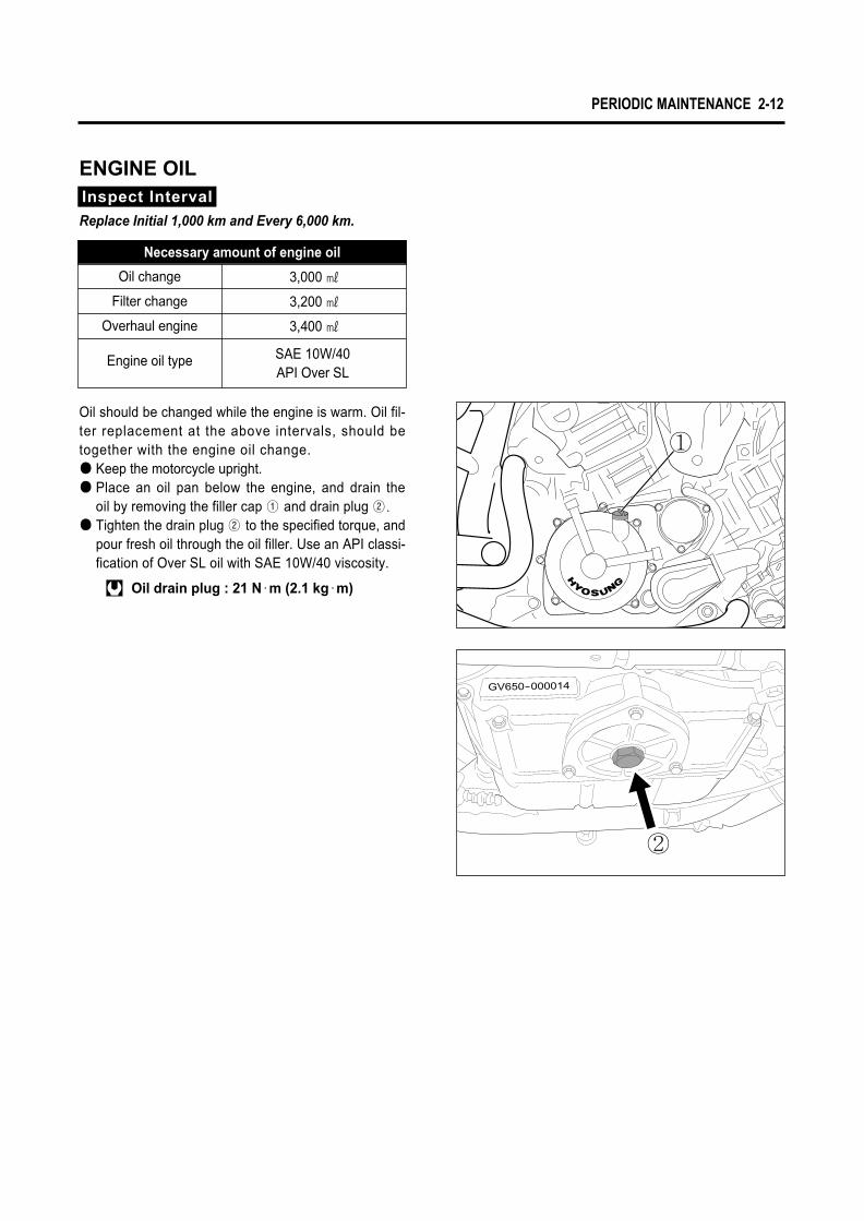
Necessary amount of engine oil
Oil change
Filter change
Overhaul engine
Engine oil type SAE 10W/40API Over SL
3,000 ㎖
3,200 ㎖
3,400 ㎖
ENGINE OILInspect Interval
Replace Initial 1,000 km and Every 6,000 km.
Oil should be changed while the engine is warm. Oil fil-ter replacement at the above intervals, should betogether with the engine oil change.● Keep the motorcycle upright.● Place an oil pan below the engine, and drain the
oil by removing the filler cap ① and drain plug ②.
● Tighten the drain plug ② to the specified torque, andpour fresh oil through the oil filler. Use an API classi-fication of Over SL oil with SAE 10W/40 viscosity.
Oil drain plug : 21 N∙m (2.1 kg∙m)
PERIODIC MAINTENANCE 2-12
①
②

2-13 PERIODIC MAINTENANCE
● Start up the engine and allow it to run for sever-al minutes at idling speed.
● Turn off the engine and wait about three minutes,then check the oil level through the inspection win-dow. If the level is below mark “L”, add oil to “F”level.If the level is above mark “F”, drain oil to “F”level.
CAUTIONNever operate the motorcycle if the engine oil levelis below the “Lower line mark(L)”in the inspec-tion window. Never fill the engine oil above the
“Upper line mark(F)”.Engine oil level being most suitable about 1mm underthe “Upper line mark(F)”of the engine oil lens. Incase of the engine oil pouring in excessively, theengine output being made insufficient.Be careful not to pour the oil excessively intoengine.
F
L
�CAUTION
Necessarily, confirm and clean the oil strainer ��when replace the engine oil (specially, when first replacement).
CAUTIONMore frequent servicing may be performed on mo-torcycles that are used under severe conditions.

PERIODIC MAINTENANCE 2-14
①
②
③④
ENGINE OIL FILTER
● Drain the engine oil as described in the engine oilreplacement procedure.
● Remove the oil filter cap ①.
● Remove the oil filter.● Install the new O-ring ②.
● Install the new oil filter.● Install the new O-ring ③ and spring ④ to the oil filter
cap.● Install the oil filter cap.
Inspect Interval
Replace Initial 1,000 km and Every 6,000 km.
CAUTIONBefore installing the oil filter cap, apply engineoil lightly to the new O-ring ③③..
▣ OIL FILTER INSTALLATION
CAUTIONWhen install the oil filter, necessarily, “HYOSUNG”
character and “16510HN910”part’s NO. install to-ward the outside, otherwise can damage the engine.
WARNINGEngine oil and exhaust pipes can be hot enough toburn you.Wait until the oil drain plug and exhaust pipes arecool enough to touch with bare hands before drain-ing oil.
LUSTER MATERIAL
HYOSUNG
16510HN910
INSERTIONDIRECTION�
OUTSIDE�
● Add new engine oil and check the oil level asdescribed in the engine oil replacement procedure.
CAUTIONUse HYOSUNG MOTORS GENUINE OIL FILTERonly, since the other make’s genuine filters andafter-market parts may differ filtering perfor-mance and durability, which could cause enginedamage or oil leaks. Hyosung motors genuine oilfilter is also not usable for the motocycles.
F
L

DRIVE BELT
Visually check the drive belt for the possible defectslisted below. (Support the motorcycle by the jackor block, turn the rear wheel slowly by hand with thetransmission shifted to Neutral.) ● Edges of the belt for cuts or unusual wear patterns● Outside ribbed surface of the belt for sign of stone
puncture● Roots of the belt teeth● Sign of cracking at the base of the belt teeth● Common types of belt wear and damage● Improper belt adjustmentIf any defects are found, the drive belt must bereplaced.Damage to the drive belt means that the pulleysmay also be damaged.I f any defects are found, the pul leys must bereplaced.
Inspect IntervalInspect Every 1,000 km.
NOTEWhen replacing the drive belt, replace thedrive belt and pulleys as a set.
2-15 PERIODIC MAINTENANCE
● Place the motorcycle on jack or block for accurateadjustment.
● After adjusting the drive belt, tighten the axle boltto the specified torque.
● Tighten both belt adjuster lock nuts �, � securely.
Rear axle bolt : 90~140 N∙m (9.0~14.0 kg∙m)
▣ ADJUSTMENT OF DRIVE BELT SLACK● Loosen the axle bolt �.
● Loosen the lock nuts �, �.
● Loosen or tighten both belt adjusters �, � until thebelt has specification of slack in the belt caseinspection hole. The marks �, � on both beltadjusters must be at the same position on the scaleto ensure that the front and rear wheels are correctlyaligned.
�
�
��
DRIVE BELT SLACK (4.5kg of Force)
When the rear tire is touched the ground 4.5~5.5 mm(0.18~0.22 in)
When the rear tire is not touched the ground5.0~6.0 mm
(0.20~0.24 in)
See Table
Engine pulley
4.5 kg of Force
Belt case inspection hole
Rear pulley
↑
�
�
�
PERIODIC MAINTENANCE 2-16
● Recheck the drive belt slack after tightening therear axle bolt.
CAUTION
The drive belt for this motorcycle is made of thespecial material.The belt should be replaced with a “Poly chainbelt” for ..Use of another belt may lead to premature beltfailure.
WARNINGBe careful not to touch the muffler when it is hot :a hot muffler can burn you.
CAUTION
● Never bend or twist when the drive belt is keptor installed.
● If the drive belt was installed with driverforcedly, damage the drive belt.
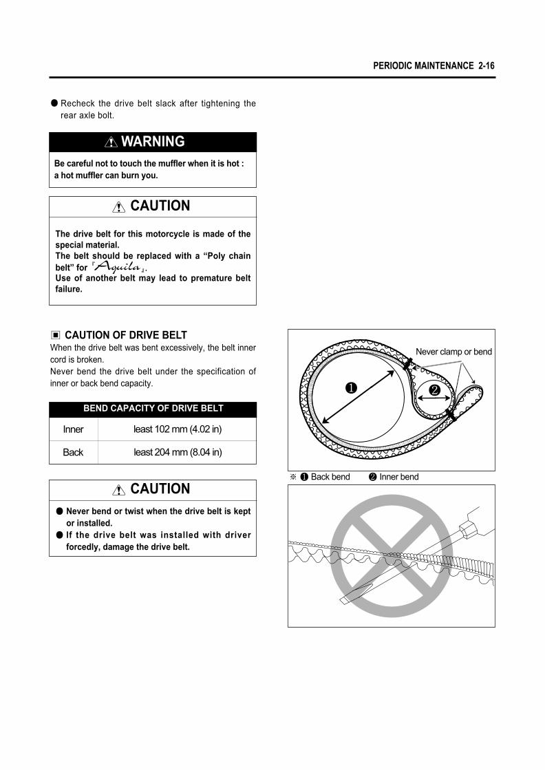
Never clamp or bend
� �
※ � Back bend � Inner bend
▣ CAUTION OF DRIVE BELTWhen the drive belt was bent excessively, the belt innercord is broken.Never bend the drive belt under the specification ofinner or back bend capacity.
BEND CAPACITY OF DRIVE BELT
Inner least 102 mm (4.02 in)
Back least 204 mm (8.04 in)

BRAKE SYSTEM
[ BRAKE HOSES & BRAKE FLUID ]Inspect Initial 1,000 km and Every 6,000 km.Replace the brake hoses Every 4 years,Replace the brake fluid Every 2 years.
▣ BRAKE FLUID LEVEL CHECK● Keep the motorcycle upright and place the handle-
bars straight.● Check the brake fluid level by observing the lower
limit line (LOWER) on the front or rear brake fluidreservoir.
● When the level is below the lower limit line (LOWER),replenish with brake fluid that meets the followingspecification.
Specification and Classification (Front brake) : DOT 3 or DOT 4(Rear brake) : DOT 4
Inspect Interval
[ BRAKE ]Inspect Initial 1,000 km and Every 6,000 km.
2-17 PERIODIC MAINTENANCE
CAUTIONDo not spill any brake fluid on the brake pad ofdisk.
[ Front Brake ]
LLOOWWEERR
▣ BRAKE PAD WEARThe extend of brake pad wear can be checkedby observing the grooved limit � on the pad. Whenthe wear exceeds the grooved limit, replace the padswith new ones.
CAUTIONReplace the brake pad as a set, otherwise braking performance will be adversely affected.
WARNINGThe brake system of this motorcycle is filled with a glycol-based brake fluid. Do not use or mix dif-ferent types of fluid such as silicone-based or petroleum-based. Do not use any brake fluid taken from old, used or unsealed containers. Never re-use brake fluid left over from the last servicing or stored for a long period.
WARNINGBrake fluid, if it leaks, will interfere with safe run-ning and immediately discolor painted surfaces. Check the brake hoses and hose joints for cracks and oil leakage before riding.
�
[ Rear Brake ]
LLOOWWEERR

PERIODIC MAINTENANCE 2-18
▣ FRONT AND REAR BRAKE PADREPLACEMENT
● Remove the brake caliper.● Remove the brake pads.● To reassemble, reverse the above sequence.
Front brake caliper mounting bolt : 18~28 N∙m (1.8~2.8 kg∙m)
Rear brake caliper mounting bolt : 18~28 N∙m (1.8~2.8 kg∙m)
[ Left side of Front Brake ]
[ Right side of Front Brake ]
[ Rear Brake ]
①
▣ FRONT AND REAR BRAKE FLUIDREPLACEMENT
● Place the motorcycle on a level surface and keep the handlebars straight.
● Remove the master cylinder reservoir cap and diaphragm.● Suck up the old brake fluid as much as possible.● Fill the reservoir with new brake fluid.
● Connect a transparent hose ① to the air bleedervalve and insert the other end of the hose into areceptacle.
Specification and Classification(Front brake) : DOT 3 or DOT 4(Rear brake) : DOT 4

● Close the air bleeder valve and disconnect thetransparent hose. Fill the reservoir with new brakefluid to the upper line.
● Replace the rear brake’s fluid with the same man-ner of the front brake.
Front brake caliper air bleeder valve : 6~8 N∙m (0.6~0.8 kg∙m)
Rear brake caliper air bleeder valve : 6~8 N∙m (0.6~0.8 kg∙m)
● Loosen the air bleeder valve and pump the brakelever until the old brake fluid is completely out of thebrake system.
2-19 PERIODIC MAINTENANCE
▣ AIR BLEEDING OF THE BRAKE FLUIDCIRCUIT
Air trapped in the brake fluid circuit acts like a cushion to absorb a large proportion of the pressure developed by the master cylinder and thus interferes with the full brak-ing performance of the brake caliper. The presence of air is indicated by “sponginess”of the brake lever and also by lack of braking force. Considering the dangerto which such trapped air exposes the machine andrider, i t is essent ia l that , af ter remount ing thebrake and restoring the brake system to the normalcondition, the brake fluid circuit be purged of air in the fol-lowing manner :● Fill the master cylider reservoir to top of the inspec-
tion window. Replace the reservoir cap to prevent dirtfrom entering it.
● Attach a hose to the air bleeder valve, and insertthe free end of the hose into a receptacle.
● Bleed air from the brake system.

PERIODIC MAINTENANCE 2-20
▣ FRONT BRAKE LAMP SWITCHThe front brake lamp switch ① is located beneath the frontbrake lever. Loosen the switch fitting screws and adjust thetiming by moving the switch body forward or backward.
▣ REAR BRAKE LAMP SWITCHAdjust the rear brake lamp switch ② so that the brakelamp will come on just before pressure is felt when thebrake pedal is depressed.
● Squeeze and release the brake lever several timesin rapid succession and sqeeze the lever fully with-out releasing it. Loosen the bleeder valve by turn-ing it a quarter of a turn so that the brake fluid runsinto the receptacle, this will remove the tension ofthe brake lever causing it to touch the handlebargrip. Then, close the air bleeder valve, pump andsqueeze the brake lever, and open the valve.Repeat this process until the fluid flowing into thereceptacle no longer contains air bubbles.
● Close the air bleeder valve, and disconnect the hose. Fill the reservoir with brake fluid to the upper line.
● Bleed the rear brake’s air with the same manner offront brake.
Front brake caliper air bleeder valve : 6~8 N∙m (0.6~0.8 kg∙m)
Rear brake caliper air bleeder valve : 6~8 N∙m (0.6~0.8 kg∙m)
NOTEWhile bleeding the brake system, replenish thebrake fluid in the reservoir as necessary. Makesure that there is always some fluid visible inthe reservoir.
CAUTIONHandle brake fluid with care : the fluid reacts chemically with paint, plastics, rubber materials, etc.
LLOOWWEERR
②
①

STEERING
Steering should be adjusted properly for smooth turning of handlebars and safe running. Overtight steering pre-vents smooth turning of the handlebars and tooloose steering will cause poor stability. Check thatthere is no play in the steering stem while graspingthe lower fork tubes by supporting the machine so thatthe front wheel is off the ground, with the wheel straightahead, and pull forward. If play is found, performsteering stem nut adjustment as described in page7-30 of this manual.
FRONT FORK
Inspect the front forks for oil leakage, scoring or scratch-es on the outer surface of the inner tubes. Replace any defective parts, if necessary.
REAR SUSPENSION
Inspect the rear shock absorber for oil leakage andmounting rubbers including engine mounting for wearand damage. Replace any defective parts, if neces-sary. (Refer to page 7-38)
Inspect Interval
Inspect Initial 1,000 km and Every 6,000 km.
Inspect Interval
Inspect Every 6,000 km.
Inspect Interval
Inspect Every 6,000 km.
2-21 PERIODIC MAINTENANCE

PERIODIC MAINTENANCE 2-22
Inspect Interval
Tighten Initial 1,000 km and Every 6,000 km.
TIRE
▣ TIRE TREAD CONDITIONOperating the motorcycle with excessively worn tires will decrease riding stability and can lead to loss of control.● Inspect shortage of tire thread’s depth by the � tire
wear indicator �.● Replace the front and rear tires at once when appear
the � tire wear indicator �.
Inspect Interval
Inspect Initial 1,000 km and Every 6,000 km.
CHASSIS BOLTS AND NUTS
Check that all chassis bolts and nuts are tightened to their specified torque. (Refer to page 8-13)
COLD INFLATIONTIRE PRESSURE
Front
Rear
SOLO RIDING
KPa
221
245
2.25
2.50
33.0
36.0
221
285
2.25
2.90
33.0
42.0
kgf/cm2 psi
DUAL RIDING
KPa kgf/cm2 psi
▣ TIRE PRESSUREIf the tire pressure is too high or too low, steering willbe adversely affected and t ire wear increased.Therefore, maintain the correct tire pressure for goodenter key roadability or shorter tire life will result. Coldinflation tire pressure is as follows.
CAUTIONThe standard tire on is 120/70-ZR 18 59W for front and 180/55-ZR 17 73W for rear. The use of tires other than those specifiedmay cause instability. It is highly recommended touse a HYOSUNG Genuine Tire.
Tire wear indicator mark
Tire wear indicator

2-23 PERIODIC MAINTENANCE
▣ ENGINE COOLANT LEVEL CHECK● Keep the motorcycle upright.● Check the engine coolant level by observing the full
line(F) and lower line(L) on the engine coolantreserve tank.
● If the level is below the lower line(L), add enginecoolant to the full line from the engine coolantreserve tank filler ①.
ENGINE COOLANT
Inspect Interval
Replace the engine coolant Every 2 years.
Engine coolant capacity
Reserve tank side
Radiator side
Engine side
230 ㎖
430 ㎖
940 ㎖
WARNING●● Engine coolant is harmful if swallowed or if it
comes in contact with skin or eyes.●● Keep out of the reach of children and animals.
CAUTION
● Use distilled water only. Water other than distilledwater can corrode and clog the aluminum radia-tor.
● The 50 : 50 mixture of distilled water and ethyleneglycol anti-freeze will provide the optimum corro-sion protection and excellent heat protection, andwill protect the cooling system from freezing attemperatures above -31℃(-24℉).
NOTEBleed air from the cooling circuit when the engineoverheat.
①

PERIODIC MAINTENANCE 2-24
● Flush the radiator with fresh water if necessary.● Install the water hose.● Tighten the coolant drain bolt ④ to the specified
torque.
Coolant drain bolt : 11~14 N∙∙m (1.1~1.4 kg∙∙m)
● Pour the engine coolant through the radiator capinlet.
▣ ENGINE COOLANT CHANGE
● Remove the right front side cover ①.● Remove the radiator cap ③.● Drain engine coolant by removing the drain bolt ④.
WARNINGDo not open the radiator cap when the engine ishot, as you may be injured by escaping hot liquidor vapor.
WARNINGYou can be injured by scalding fluid or steam ifyou open the radiator cap when engine is hot.After the engine cools, wrap a thick cloth aroundcap and carefully remove the cap by turning it aquarter to allow pressure to escape and then turnthe cap all the way off.
▣ OPEN THE RADIATOR CAPRemove the right front side cover ① to operate theradiator cap ③.To disassemble the right front side cover ①, removethe two mounting bolt ②. ①
②
③
④
● Bleed the air from the engine coolant circuit as fol-lowing procedure.
NOTEFor engine coolant information, refer to page 5-1
Engine coolant capacity
Reserve tank side
Radiator side
Engine side
230 ㎖
430 ㎖
940 ㎖
2-25 PERIODIC MAINTENANCE
CAUTION
Repeat the above procedure several times andmake sure that the radiator is filled with enginecoolant up to the reserve tank full line(F).
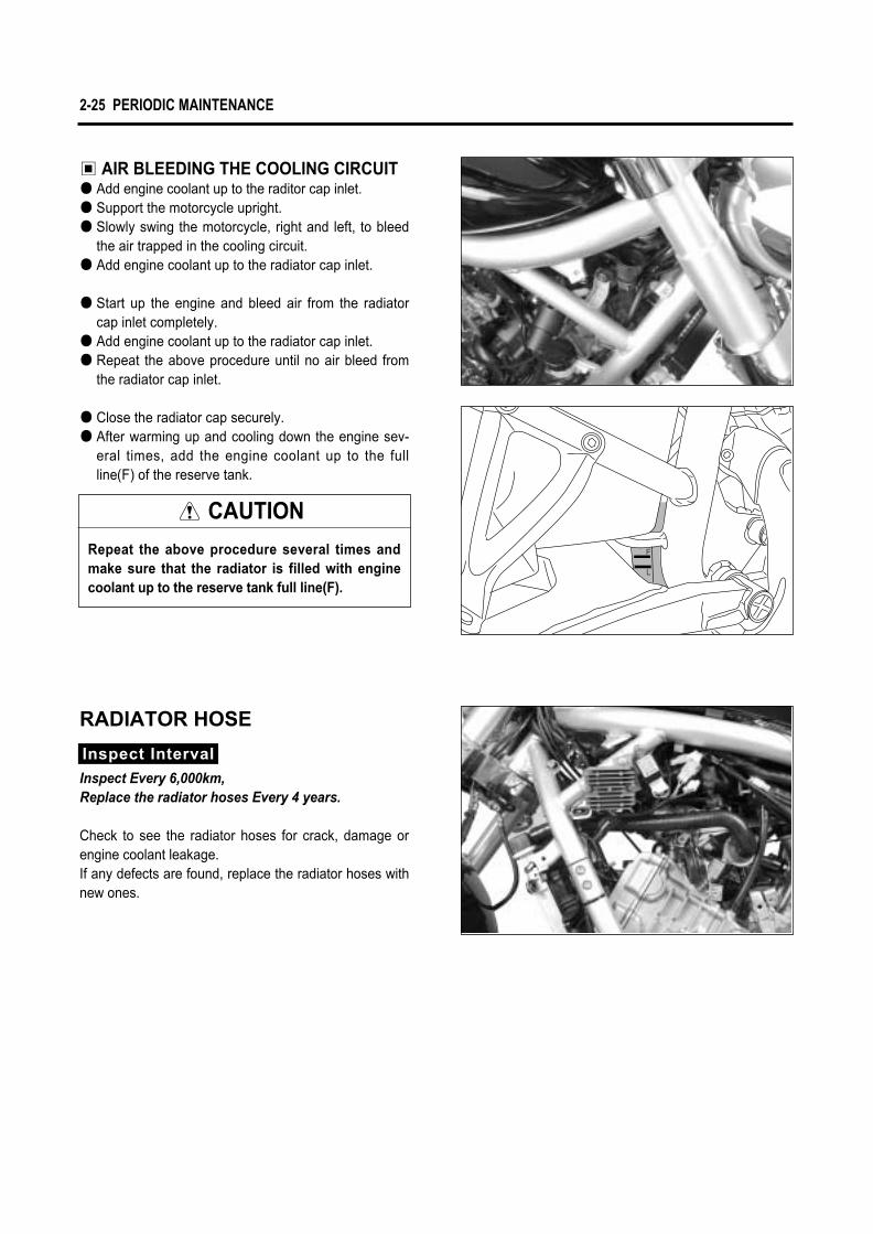
▣ AIR BLEEDING THE COOLING CIRCUIT● Add engine coolant up to the raditor cap inlet.● Support the motorcycle upright.● Slowly swing the motorcycle, right and left, to bleed
the air trapped in the cooling circuit.● Add engine coolant up to the radiator cap inlet.
● Start up the engine and bleed air from the radiatorcap inlet completely.
● Add engine coolant up to the radiator cap inlet.● Repeat the above procedure until no air bleed from
the radiator cap inlet.
● Close the radiator cap securely.● After warming up and cooling down the engine sev-
eral times, add the engine coolant up to the fullline(F) of the reserve tank.
RADIATOR HOSE
Check to see the radiator hoses for crack, damage orengine coolant leakage.If any defects are found, replace the radiator hoses withnew ones.
Inspect Interval
Inspect Every 6,000km,Replace the radiator hoses Every 4 years.

PERIODIC MAINTENANCE 2-26
Low compression pressure can indicate some of thefollowing conditions :● Excessively worn cylinder wall● Worn-down piston or piston rings● Piston rings stuck in grooves● Poor seating of valves● Ruptured or otherwise defective cylinder head gasket
Remove the parts concerned and test the compres-sion pressure in the following manner.● Loosen the radiator cover mounting bolts from the
frame.● Loosen the radiator mounting bolts.
● Using the fuel tank stay, lift the rear end of the fueltank and prop it up. (Refer to page 2-2)
● Remove all the spark plug.● Fit the compression gauge in one of the plug holes,
while taking care that the connection is tightened.● Keep the throttle grip in full-open position.● Crank the engine a few seconds with the starter, and
record the maximum gauge reading as the compres-sion of cylinder.
Overhaul the engine in the following cases :● Compression pressure in one of the cylinder is less
than 12kg/㎠.● The difference in compression pressure between two
cylinder is more than 2kg/㎠.● All compression pressure readings are nearly 12kg/㎠
even when they measure more than 12kg/㎠.
▣ COMPRESSION TEST PROCEDURE
Compression gauge : 09915-64510
COMPRESSION PRESSUREThe compression of a cylinder is a good indicator ofits internal condition.The decision to overhaul the cylinder is often basedon the results of a compression test. Periodic mainte-nance records kept at your dealership should includecompression reading for each maintenance service.
Standard
Service limit
Difference
14 kg/cm2 (at 500 rpm)
12 kg/cm2 (at 500 rpm)
2 kg/cm2 (at 500 rpm)
Compression pressure
NOTE� Before testing the engine for compression
pressure, make sure that the cylinder headbolts are tightened to the specified torquevalues and valves are properly adjusted.
� Have the engine warmed up by idling beforetesting.
� Be sure that the battery used is in fully-charged condition.
CAUTION●● Be careful not to damage the radiator fins.●● Do not extract the radiator hose.
WARNINGThe hot radiator and the hot engine can burn you.Wait until the radiator and the engine are coolenough to touch.

2-27 PERIODIC MAINTENANCE
▣ HIGH OIL PRESSURE● Engine oil viscosity is too high● Clogged oil passage● Combination of the above items
▣ OIL PRESSURE TEST PROCEDURECheck the oil pressure in the following manner.● Remove the oil check plug and install the adapter of oil
pressure gauge at the removed position.● Connect an engine tachometer.● Warm up the engine as follows :
Summer : 10 min. at 2,000 rpm.Winter : 20 min. at 2,000 rpm.
● After warming up, increase the engine speed to 3,000 rpm. (with the engine tachometer), and read the oil pressure gauge.
Engine tachometer : 09900-26006Oil pressure gauge : 09915-74510
▣ LOW OIL PRESSURE● Oil leakage from the oil passage● Damaged O-ring● Defective oil pump● Combination of above items
OIL PRESSURECheck the oil pressure periodically. This will give a good indication of the condition of the moving parts.
If the oil pressure is lower or higher than the specification, the following causes may be considered.
2.0 ~ 6.0 ㎏/㎠(at 60 ℃∙3,000 rpm)
Standard
Oil pressure
ENGINE
3
ENGINE REMOVAL AND REINSTALLATION …………………… 3- 1
ENGINE REMOVAL ……………………………………………………… 3- 1
ENGINE REINSTALLATION …………………………………………… 3- 7
ENGINE DISASSEMBLY………………………………………………… 3- 9
STARTER MOTER ……………………………………………………… 3- 9
THERMOSTAT …………………………………………………………… 3- 9
2ND AIR VALVE ………………………………………………………… 3-10
CYLINDER HEAD COVER ……………………………………………… 3-10
PISTON …………………………………………………………………… 3-14
MAGNETO COVER ……………………………………………………… 3-14
MAGNETO ROTOR ……………………………………………………… 3-15
CLUTCH COVER ………………………………………………………… 3-16
CLUTCH …………………………………………………………………… 3-17
PRIMARY DRIVE GEAR ………………………………………………… 3-18
OIL PUMP ………………………………………………………………… 3-18
GEARSHIFT SHAFT……………………………………………………… 3-19
ENGINE COMPONENT INSPECTION AND SERVICE ……… 3-21
ENGINE REASSEMBLY ………………………………………………… 3-39
CONTENTS
CAUTION� Mark an identification of assembly location on each removed part so that each will be restored
to the original position during reassembly.� Wash clean and dry the removed parts before inspecting and measuring.� Oil the rotating or sliding parts before assembly.� Make sure to use the correct type of lubricant where specified.� Check that each rotating or sliding part moves or operates smoothly after assembly.� Make sure to follow the bolt tightening order where specified.� If the correct length of the bolt is confused when tightening the crankcase or cover, insert all the bolts
and check that the tightening margin is equal in each bolt.

3-1 ENGINE
▣ AIR CLEANER● With the four hose and the two clamp screw loos-
ened, remove the air cleaner case.
ENGINE REMOVAL ANDREINSTALLATION
ENGINE REMOVAL
● Remove the seat. (Refer to page 7-1)● Remove the fuel tank. (Refer to page 4-1)● Remove the frame cover. (Refer to page 7-2)● Disconnect the battery � lead wire ①.
NOTEIf the engine is dirtied, wash the machinewith a suitable cleaner before removing theengine.
CAUTIONFirst, disconnect the � lead wire.
● Drain engine oil. (Refer to page 2-12)
● Drain engine coolant. (Refer to page 2-24)
①

ENGINE 3-2
▣ COOLING FAN● With the two mounting bolts ② removed, remove the
right front side cover ①.● Remove the radiator cap bolt ③.
● Disconnect the cooling fan thermo-switch lead wirecoupler ⑤.
● Disconnect the radiator inlet hose ⑥.
● Remove the four radiator cover mounting bolts.● Remove the radiator cover.● Disconnect the radiator outlet hose ④.● Remove the radiator mounting bolts.
● Disconnect the reserve tank hose ⑦.● Disconnect the cooling fan motor lead wire coupler
⑧.● Remove the radiator.
CAUTIONBe careful not to bend the radiator fin.
⑥
⑤
④
③
⑦⑧
①
②

3-3 ENGINE
▣ CLUTCH CABLE● Disconnect the clutch cable end out of clutch lever.● Disconnect the clutch cable end out of clutch release
arm.
▣ EXHAUST PIPE AND MUFFLER● With the exhaust pipe bolts �, rear exhaust pipe
connecting bolts � and muffler mounting bolts �removed, remove the exhaust pipes and muffler.
▣ CARBURETOR● Remove the carburetor after removed the intake pipes.
(Refer to page 4-4)● Disconnect the vacuum hoses ①.
[ Front Cylinder ]
[ Rear Cylinder ]
�
�
①

▣ ELECTRIC PARTS● By taking out the spark plug caps, remove the spark
plug.
● Remove the starter motor lead wire.
● Disconnect the engine coolant temperature sensorlead wire ①.
ENGINE 3-4
[ Front Cylinder ] [ Rear Cylinder ]
�
�
①

3-5 ENGINE
● Remove the engine ground lead wire ①.
● Disconnect the two magneto coupler ②.● Disconnect the neutral switch terminal ③.● Disconnect the side-stand switch lead wire couper
④.
▣ ENGINE PULLEY● Remove the engine pulley cover ⑤.
● Disconnect the front side of crankcase breather hose⑥ and rear side of crankcase breather hose ⑦.
②③
⑤
⑦
④
⑥
①

ENGINE 3-6
● Remove the frame down tube.● Support the engine using an engine jack.● Remove the engine mounting nuts, bolts and engine
mounting lock nuts with the special tool.
● Remove the engine from the frame.
Engine mounting socket wrench (M20): 09940H30010
CAUTIONRemove the carburetor when removing orinstalling the engine necessarily.When removing the carburetor, loosen the intakepipe mounting bolts at the same time.
● Remove the gearshift arm ①.● Flatten the lock washer.● Remove the engine pulley nut ② and washer.
● Remove the engine pulley.
NOTEWhen loosening the engine pulley nut, depressthe brake pedal.
NOTEIf it is difficult to remove the engine pulley,loosen the rear axle bolt, belt adjusters ③∙④
to provide additional belt slack. (Refer to page 2-15)
①
②
③ ④

3-7 ENGINE
ENGINE REINSTALLATIONReinstall the engine in the reverse order of engineremoval.
● Install the engine mounting bolts, nuts and enginemounting lock nuts with the special tool.
Engine mounting socket wrech (M20): 09940H30010
● Tighten the engine mounting bolts, nuts and enginemounting lock nuts to the specified torque.
Engine mounting bolt ①①,, ②②
: 15��30 N∙∙m (1.5��3.0 kg∙∙m)Engine mounting nut ③③
: 45��70 N∙∙m (4.5��7.0 kg∙∙m)Engine mounting lock nut (M20) ④④
: 35 ~ 50 N∙∙m (3.5��5.0 kg∙∙m)● Tighten the frame down tube mounting bolts ⑤ to the
specified torque.Frame down tube mounting bolt ⑤⑤
: 22 ~ 35 N∙∙m (2.2��3.5 kg∙∙m)
CAUTIONSet the part �� of engine mounting bolt ①① aligncenter line by the hand temporarily and installthe engine mounting bolt to the specifiedtorque.If otherwise, it is damage to the thread ofengine mounting bolt.
NOTESet the part �� of swingarm pivot shaft ��
align center l ine by the hand temporarilyand install the swingarm pivot shaft to thespecified torque.
Swingarm pivot shaft ��: 15~30 N∙∙m (1.5~3.0 kg∙∙m)
Swingarm pivot nut ��: 50~70 N∙∙m (5.0~7.0 kg∙∙m)
Swingarm mounting lock nut (M26) ��: 70~80 N∙∙m (7.0~8.0 kg∙∙m)
①
④
①
②⑤
�
�
�
�③
③
③ �
�

ENGINE 3-8
▣ ENGINE PULLEY● Loosen the rear axle bolt ① and belt adjusters ②,
left and right.● Install the engine pulley.
● Tighten the engine pulley nut ③ to the specifiedtorque.
● Bend the lock washer securely.
Engine pulley nut: 130~160 N∙m (13.0~16.0 kg∙m)
NOTEWhen t ightening the engine pul ley nut ,depress the rear brake pedal.
● Install the gearshift arm and adjust the gearshift leverheight. (Refer to page 2-10)
● Install the breather hose and engine pulley cover.● Connect each electric parts and its couplers.
(Refer to page 8-24~30)● Install the exhaust pipes and mufflers.● Install the carburetor and air cleaner.
(Refer to page 4-7)● Install the radiator and radiator cover.
(Refer to page 5-4)
● Af te r remount ing the eng ine , the fo l low ingadjustments are necessary.
Engine idling speed Refer to page 2-9Throttle cable play Refer to page 2-9Clutch cable play Refer to page 2-10Drive belt Refer to page 2-15Gearshift lever height Refer to page 2-10Engine oil level Refer to page 2-13Engine coolant Refer to page 2-23
②
②
①
③

3-9 ENGINE
ENGINE DISASSEMBLY
STARTER MOTOR● Remove the starter motor.
● Remove the gear position switch.● Remove the contacts ① and springs ②.
THERMOSTAT● Remove the thermostat case ③ along with the hose
④.
CAUTIONIdentify the position of each removed part.Organize the parts in their respective groups sothat they can be reinstalled in their originalpositions.
NOTEThermostat inspection and servicing
: Refer to page 5-8
③
②
①
④

ENGINE 3-10
● To set the piston at TDC (Top Dead Center).
● Remove the cam chain tensioner adjuster �, �.
CYLINDER HEAD COVER● Remove the cylinder head cover.
2ND AIR VALVE● Remove the 2nd air valve ① with the bracket.
CAUTIONAlign the index mark on the magneto rotor with the index mark on the magneto cover as turn the crankshaft counter-clockwise.To set piston at TDC(Top Dead Center) of the compression stroke as align the “|F”mark for front cylinder and the “|R”mark for rear cylin-der.
[ Front Cylinder ]
①
�

3-11 ENGINE
● With the three bolts removed, remove the cam chainguide NO.2 ①.
● Remove the camshaft housing ②.
● Remove the camshaft (IN.∙EX.) ③.
NOTEMark an identification of assembly location oneach removed parts so that each wi l l berestored to the or iginal posit ion duringreassembly.
[ Rear Cylinder ]
�
①
②
②
③

● Remove the tappet and the shim.
CAUTIONDraw out the tappet and shim with the strong magnet not to be scratched.
ENGINE 3-12
● Loosen the six cylinder head bolts.
● Remove the chain guide NO.1 and cylinder head.
● Loosen the cylinder head base bolt.
NOTEWhen loosening the cyl inder head bolts,loosen each bolt little by little diagonally.
3-13 ENGINE
Valve spring compressor : 09916-14510Valve spring compressor attachment
: 09916-14520
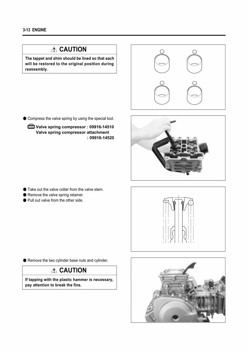
● Compress the valve spring by using the special tool.
● Take out the valve cotter from the valve stem.● Remove the valve spring retainer.● Pull out valve from the other side.
CAUTIONThe tappet and shim should be lined so that each will be restored to the original position during reassembly.
● Remove the two cylinder base nuts and cylinder.
CAUTIONIf tapping with the plastic hammer is necessary, pay attention to break the fins.

MAGNETO COVER● Remove the magneto cover.
ENGINE 3-14
PISTION● Place a clean rag over the cylinder base to prevent
piston pin circlips from dropping into crankcase.Remove the piston pin circlips with long-nose pliers.
Piston pin puller : 09910-34510
● Remove the piston pin by using the special tool.
● Remove the rear cylinder head and cylinder with thesame manner of the front cylinder head and cylinderremoval.
NOTEMake an identification on each piston head toconfirm the cylinder.
Rear Cylinder
Front Cylinder

3-15 ENGINE
● Remove the starter idle shaft ①, starter idle gear②.
Conrod holder : 09910-20115
Rotor remover : 09930-30165
MAGNETO ROTOR● With the magneto rotor held immovable using the
special tool, loosen the rotor nut.
● Remove the magneto rotor by using the special tool.
● Remove the key ③.● Remove the starter driven gear ④.● Remove the cam chain ⑤.
②
①
③
④
⑤

ENGINE 3-16
CLUTCH COVER● Remove the clutch release arm ②.
● Remove the clutch cover bolts.● Remove the clutch cover ③.
● Remove the cam chain tensioner ①.
NOTEWhen remove or inspect the clutch drive anddriven plate, remove only the clutch pressurecover ④④.
①
②
③
④

3-17 ENGINE
CLUTCH● With the primary drive gear held immovable using
the special tool, remove the clutch spring mountingbolts diagonally.
Conrod holder : 09910-20115● Remove the disk pressure ①.
● Remove the clutch drive plates NO. 1 and drivenplates.
● Remove the spring washer and spring washer seat.● Remove the clutch drive plate NO. 2.
● Flatten the lock washer ②.
Clutch sleeve hub holder : 09920-53710
● With the clutch sleeve hub held immovable usingspecial tool, remove the clutch sleeve hub nut.
①
②

ENGINE 3-18
● Remove the cam chain ⑥.● Remove the cam chain tensioner ⑦.
OIL PUMP● Remove the circlip ⑧ and oil pump driven gear ⑨.
● Remove the clutch sleeve hub ① and primary driv-en gear assembly ② .
Conrod holder : 09910-20115
PRIMARY DRIVE GEAR● With the crankshaft held immovable using special
tool, remove the primary drive gear nut ③.
● Remove the water pump drive gear ④ and primarydrive gear ⑤.
CAUTIONThis nut has left-hand thread. If turning it counter-clockwise ( ), it may cause damage.Pay attention at the primary drive gear nut witha washer, and water pump drive gear with awasher.
①②
③
④
⑤
⑥
⑦
⑧
⑨

3-19 ENGINE
● Remove the pin ① and shim.● With the three screws loosened, remove the oil
pump ②.
GEARSHIFT SHAFT● Draw out the gearshift shaft ③.
● Remove the gearshift cam stopper ④.
● Loosen the gearshift cam plate bolt ⑤.
● Remove the gearshift cam stopper plate.
● Remove the crankcase securing bolts, right and left.
NOTELoosen the crankcase bolts diagonally andsmaller sizes first.
②
①
③
④
⑤
ENGINE 3-20
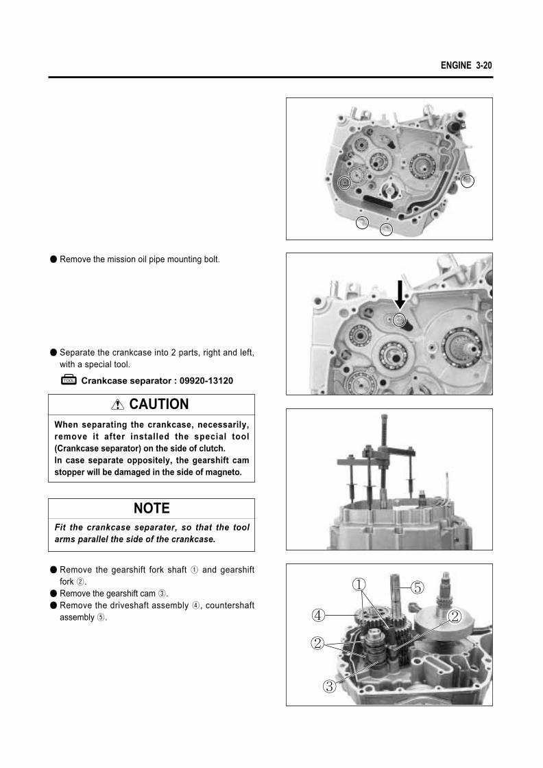
● Remove the gearshift fork shaft ① and gearshiftfork ②.
● Remove the gearshift cam ③.● Remove the driveshaft assembly ④, countershaft
assembly ⑤.
● Separate the crankcase into 2 parts, right and left,with a special tool.
Crankcase separator : 09920-13120
CAUTIONWhen separating the crankcase, necessarily,remove it after installed the special tool(Crankcase separator) on the side of clutch. In case separate oppositely, the gearshift camstopper will be damaged in the side of magneto.
NOTEFit the crankcase separater, so that the toolarms parallel the side of the crankcase.
● Remove the mission oil pipe mounting bolt.
① ⑤
②
②④
③

3-21 ENGINE
● Remove the crankshaft by using the special tool.
Crankcase separator : 09920-13120
Cylinder head distortion
Service limit
0.05 mm (0.002 in)
Valve head thickness ��Service limit
0.5 mm (0.02 in)
Valve stem runoutService limit
0.05 mm (0.002 in)
ENGINE COMPONENT INSPECTION AND SERVICE
Thickness gauge : 09900-20806
Vernier calipers : 09900-20101
◉ VALVE FACE WEARVisually inspect each valve face for wear. Replace anyvalve with an abnormally worn face. The thickness ofthe valve face decreases as the face wears. Measurethe valve head thickness �. If it is out of specification,replace the valve with a new one.
◉ VALVE STEM RUNOUTCheck the valve stem for abnormal wear or bend.Place the valve on V-blocks and measure runout.If the service limit is exceeded or abnormal condi-tion exists, replace the valve.
Dial gauge : 09900-20606Magnetic stand : 09900-20701V-block : 09900-21304
◉ CYLINDER HEAD DISTORTIONDecarbonate in combustion chamber.Check the gasket surface of the cylinder head for distor-tion with a straightedage and thickness gauge, taking aclearance reading at several places as indicated. If thelargest reading at any position of the straightedgeexceeds the limit, replace the cylinder head.
CAUTIONBe sure to identify each removed part as to its loca-tion, and lay the parts out in groups designated as
“Front cylinder”, “Rear cylinder”, “Exhaust”,“Intake”, so that each will be restored to the origi-nal location during assembly.
�

ENGINE 3-22
Cam height ��
Intake cam
Exhaust cam
Service limit
34.98 mm (1.377 in)
33.08 mm (1.302 in)
Camshaft journal
oil clearance
(IN & EX)
Service limit
0.15 mm (0.006 in)
Valve clearance
0.28 ~ 0.32 mm(0.011 ~ 0.013 in)
0.1 ~ 0.2 mm (0.004 ~ 0.008 in)
Standard (When cold)
◉ CAMSHAFTThe camshaft should be checked for runout and also forwear of cams and journals if the engine has been notedto produce abnormal noise or vibration or a lack of out-put power. Any of these abnormality could be caused bya worn camshaft.
▣ CAMSHAFT WEARWorn-down cams are often the cause of mistimed valveoperation resulting in reduced output power.The limit of cam wear is specified for both intake andexhaust cams in terms of cam height �, which is to bemeasured with a micrometer. Replace camshafts iffound it worn down to the limit.
▣ CAMSHAFT JOURNAL WEARDetermine whether or not each journal is worn down tothe limit by measuring the oil clearance with thecamshaft installed in place.● Use the plastigauge to read the clearance at the
widest portion, which is specified as follows :
Micrometer((25~50 mm)) : 09900-20202
◉ TAPPET & SHIM WEARWhen measuring the valve clearance, the clearance should be within the standard range.
Exhaust valve
Intake valve
(B.T.D.C)Intake open
(T.D.C)
(A.T.D.C)Exhaust close
(B.B.D.C)Exhaustopen
(A.B.D.C)Intake close
(B.D.C)Valve timing diagram
�

3-23 ENGINE
Valve head radialrunout
Service limit
0.03 mm (0.0012 in)
Valve guide-valve stem clearance Standard
0.020~0.047 mm
(0.0008~0.0019 in)
0.030~0.057 mm
(0.0012~0.0022 in)
Valve stem diameter Standard
4.465~4.480 mm (0.1758~0.1764 in)
4.455~4.470 mm (0.1754~0.1760 in)
IN.
EX.
◉ VALVE HEAD RADIAL RUNOUTPlace a dial gauge as shown and measure valvehead radial runout.If the service limit is exceeded, replace the valve.
Dial gauge : 09900-20606Magnetic stand : 09900-20701V-block : 09900-21304
Dial gauge : 09900-20606Magnetic stand : 09900-20701
Micrometer(0~25 mm) : 09900-20201
◉ VALVE STEM DIAMETERMeasure the valve stem outside diameter.If the diameter measured exceeds the standard, replace the valve.
◉ VALVE GUIDE-VALVE STEMCLEARANCE
Measure the clearance in the valve guide-valve stem, by rigging up the dial gauge as shown. If the clearanceis measured exceeds the limit specified below, thendetermine whether the valve or the guide should bereplaced to reduce the clearance to within the standardrange :
EX.
IN.
● Inspect the tappet for wear and scratch.If modification or scratch is present, replace the tap-pet.
● When you checked the valve clearance, if the valveclearance is wide please replace the present shiminto thick one, if the valve clearance is narrow pleasereplace the present shim into thin shim. (Refer to page 8-31∙32)
▣ SHIM KINDThere are 41 kinds of shim which thickness is increasedby each 0.025 mm from 1.20 mm to 2.20 mm.

ENGINE 3-24
◉ VALVE SPRINGThe force of the coil spring keeps the valve seat tight. A weakened spring results in reduced engine power out-put and often accounts for the chattering noise coming from the valve mechanism.Check the valve springs for proper strength by measuring their free length and also by the force requiredto compress them. If the spring length is less than theservice limit or if the force required to compress thespring does not fall within the specified range, replaceboth the inner and outer springs as a set.
Valve spring free length
Inner
Outer
Service limit
36.8 mm (1.45 in)
39.8 mm (1.57 in)
Valve spring tension
Inner
Outer
Standard
4.2~4.8 kgf
(9.3~10.6 lbs)
at length 29.9 mm (1.18 in)
17.0~19.6 kgf
(37.5~43.2 lbs)
at length 33.4 mm (1.32 in)
Standard
81.500~81.515 mm
(3.2087~3.2093 in)
Service limit
81.575 mm
(3.2116 in)
Cylinder bore
Cylinder distortionService limit
0.05 mm (0.002 in)
Venier calipers : 09900-20101
Thickness gauge : 09900-20806
Cylinder gauge set : 09900-20508
◉ CYLINDER BOREMeasure the cylinder bore diameter at six place. If any one of the measurements exceeds the limit, overhaul the cylinder and replace the piston with an oversize, or replace the cylinder.
◉ CYLINDER DISTORTIONCheck the gasketed surface of the cylinder for distor-tion with a straightedge and thickness gauge, taking aclearance reading at several places as indicated.I f t he l a rges t read ing a t any pos i t i on o f t hestraightedge exceeds the limit, replace the cylin-der.

3-25 ENGINE
◉ CAM CHAIN TENSIONERADJUSTER
Check that the push rod slides smoothly with the lock shaft handle ① clockwise.If it does not slide smoothly, replace the cam chaintensioner adjuster with a new one.
Piston oversize 0.5, 1.0 mm (0.02, 0.04 in)
Piston diameter
Service limit
81.380 mm
(3.2039 in)
◉ CAM CHAIN TENSIONERCheck the contacting surface of the cam chain tensioner.If it is worn or damaged, replace it with a new one.
◉ CAM CHAIN AND CAM CHAINGUIDE
Check the cam chain for wear, damage and kinked or bind-ing links. If any defects are found, replace it with a new one.Check the cam chain guide for wear and damage. If itis found to be damaged, replace it with a new one.
Micrometer(75~100 mm) : 09900-20204
◉ PISTON DIAMETER INSPECTIONMeasure the outside diameter of piston in the direction per-pendicular to the piston pin axis at the height from the skirt as shown in the illustration using a micrometer.If the measurement is found less than the servicelimit, replace the piston.
①
20mm (0.79in)

ENGINE 3-26
Standard
0.045~0.075 mm
(0.0018~0.0030 in)
Service limit
0.120 mm
(0.0047 in)
Piston-to-cylin-der clearance
◉ PISTON-TO-CYLINDERCLEARANCE
To determine the piston-to-cylinder clearance, calculate the difference between the cylinder bore and outside diameter of the piston.
◉ PISTON RING FREE END GAPINSPECTION
Before installing piston rings, measure the free end gap of each ring using vernier calipers. If the gap is less than the service limit, replace the ring.
◉ PISTON PIN DIAMETERINSPECTION
Using a micrometer, measure the piston pin outside diameter at three position, both the ends and the center.If any of the measurements is founds less than the ser-vice limit, replace the pin.
Piston pin hole boreService limit
20.030 mm (0.7886 in)
Piston pin diameterService limit
19.980 mm (0.7866 in)
Piston ring free end gap Standard
Approx 9.9 mm (0.390 in)
Approx 10.5 mm (0.413 in)
1st
2nd
Dial calipers : 09900-20605
◉ PISTON PIN HOLE BOREUsing a dial calipers, measure the piston pin hole bore both the vertical and horizontal directions.If the measurement exceeds the service limit, replace the piston.
Micrometer(0~25 mm) : 09900-20201
Vernier calipers : 09900-20101
Piston ring free end gap Service limit
7.9 mm (0.311 in)
8.4 mm (0.330 in)
1st
2nd

3-27 ENGINE
◉ PISTON RING END GAP INSPECTIONInsert the piston ring squarely into the cylinder usingthe piston head.Measure the end gap with a thickness gauge.If the gap exceeds the service limit, replace the piston ring.
Piston ring end gap
(Assembly condition)Standard
0.20~0.35 mm
(0.008~0.013 in)
0.20~0.35 mm
(0.008~0.013 in)2nd
1st
Thickness gauge : 0990-20806
Piston ring end gap(Assembly condition)
1st
2nd
Service limit
0.5 mm (0.020 in)
0.7 mm (0.028 in)
Service limit
0.180 mm (0.007 in)
0.150 mm (0.006 in)
Piston ring-groove clearance
1st
2nd
◉ PISTON RING-TO-GROOVECLEARANCE INSPECTION
Remove carbon deposit both from the piston ring and its groove.Fit the piston ring into the groove. With the ring com-pressed and lifted up, measure the clearance on the bottom side of the ring using a thickness gauge.
Standard
0.970~0.990 mm
(0.0382~0.0390 in)
Piston ring thickness
StandardPiston ring-groove width
Micrometer(0~25 mm) : 09900-20201Thickness gauge : 09900-20806
Oil
2nd
1st
2.01~2.03 mm(0.079~0.080 in)
1.01~1.03 mm(0.040~0.041 in)
1.21~1.23 mm(0.0476~0.0484 in)
2nd
1st
1.170~1.190 mm(0.0461~0.0469 in)

ENGINE 3-28
▣ Oversize oil ringThe following two types of oversize oil ring are used.They bear the following identification marks.
Color classification
Painted red
Painted yellow
Oversize oil ring
0.5 mm
1.0 mm
2nd
05
10
1st
05
10
Oversize piston ring
0.5 mm
1.0 mm
◉ OVERSIZE RINGS▣ Oversize piston ringThe following two types of oversize piston ring are used.They bear the following identification numbers.
◉ CONROD SMALL END INSIDEDIAMETER INSPECTION
Using a dial calipers, measure the conrod small end inside diameter both in vertical and horizontal directions. If any of the measurements exceeds the servicelimit, replace the conrod.
Standard
20.006~20.014 mm
(0.7876~0.7880 in)
Service limit
20.040 mm
(0.7890 in)
Conrod smallend I.D.
◉ CONROD DEFLECTION INSPEC-TION
Move the small end sideways while holding the big end immovable in thrust direction.Measure the amount of deflection.Turn the conrod and see if it moves smoothly without play and noise. This method can check the extent ofwear on the parts of the conrod’s big end.
Conrod deflectionService limit
3.0mm (0.12 in)
Dial calipers : 09900-20605
Dial gauge : 09900-20606Magnetic stand : 09900-20701V-block : 09900-21304

3-29 ENGINE
◉ CONROD BIG END SIDECLEARANCE INSPECTION
Using a thickness gauge, measure the side clearance at the conrod big end. If the measurement is out of stan-dard value, measure the conrod big end and the crank pin widths individually to determine which one is to be replaced.
Standard
0.17~0.32 mm
(0.007~0.013 in)
Service limit
0.50 mm
(0.020 in)
Conrod big end side clearance
◉ CRANKSHAFT RUNOUTINSPECTION
With the right and left crank journals supported with V-block, turn the crankshaft slowly. At this time, measure the crankshaft end runout using a dial gauge. If the runout exceeds the service limit, replace the crankshaft.
Crankshaft runoutService limit
0.05 mm (0.002 in)
◉ CRANKSHAFT REASSEBLYMeasure the width between the webs referring to the fi-gure below when rebuilding the crankshaft.
Width between webs
Standard
96.9~97.1 mm
(3.815~3.823 in)
◉ MAGNETO COVER▣ MAGNETO INSPECTION (Refer to page 6-4)▣ DISASSEMBLY● Remove the stator ①.
Dial gauge : 09900-20606Magnetic stand : 09900-20701V-block : 09900-21304
96.9~97.1mm
①

ENGINE 3-30
◉ STARTER CLUTCHInstall the starter driven gear onto the starter clutch and turn the starter driven gear by hand(the gear turns inonly one direction). The starter driven gear should turnsmoothly. If excessive resistance is felt while turning thestarter driven gear, inspect the starter clutch. Also,inspect the surface of the starter driven gear which con-tacts the starter clutch, for wear or damage. If any wearor damage is found, replace the defective parts.
▣ DISASSEMBLY● With the magneto rotor held immovable, remove the
starter clutch bolts.
▣ REASSEMBLY● Apply a small quantity of THREAD LOCK “1324”to
the starter clutch bolts and tighten them to the spec-ified torque with the magneto rotor held immovable.
Thread Lock “1324”
Starter clutch bolt: 23~28 N∙m (2.3~2.8 kg∙m)
◉ STARTER DRIVEN GEAR▣ STARTER DRIVEN GEAR BUSHInstall the starter driven gear bush ① and gear ② ontothe crankshaft and turn the starter driven gear by hand.Inspect the starter driven gear bush for smooth rotationand any abnormal noise. If the bush does not turnsmoothly or there is any abnormal noise, replace it.
②
①

3-31 ENGINE
Bearing remover (20~35 mm): 09923-74510
◉ DISASSEMBLY● Remove the bush using the special tool.
◉ OIL JET▣ REMOVAL● Remove the oil jet ①, ② from the right crankcase
half.
● Remove the oil jet ③ from the left crankcase half.
NOTEIf it is difficult to remove the oil jet, use a sting.
①
②
③

ENGINE 3-32
▣ INSPECTION AND CLEANING● Check the oil jets for clogging.● If they are clogged, clean their oil passage with a
proper wire and compressed air.
▣ INSTALLATION● Fit the new O-ring to each oil jets.
● Install the oil jet ① to the oil hole of crankcase.
● Apply engine oil to the O-ring.
Oil seal remover : 09913-50121
◉ CLUTCH COVER▣ OIL FILTER REPLACEMENT
(Refer to page 2-14)▣ DISASSEMBLY● Remove the circlip and right crankshaft oil seal.
CAUTIONUse the new O-ring to prevent oil leakage.
NOTEPush the oil jet the crankcase until it stops.
①

3-33 ENGINE
Bearing installer : 09913-75820
▣ REASSEMBLY● Drive in the oil seal using the special tool.
● Install the circlip.
Service limit
0.1 mm (0.004 in)
Clutch driven plate distortion
Thickness gauge : 09900-20806
◉ CLUTCH DRIVEN PLATESMeasure each clutch driven plate for distortion using the thickness gauge. If a clutch driven plate is not within the service limit, replace the clutch plates as a set.
Standard
2.92~3.08 mm (0.115~0.121 in)
3.42~3.58 mm (0.135~0.141 in)
NO.1
NO.2
Clutch drive plate thickness
Vernier calipers : 09900-20101
◉ CLUTCH DRIVE PLATESMeasure the thickness and claw width of the clutch drive plates using vernier calipers. If a clutch drive plate is not within the service limit, replace the clutch plates as aset.
Service limit
2.62 mm (0.103 in)
3.12 mm (0.123 in)
NO.1
NO.2
Clutch drive plate thickness
Standard
15.9~16.0 mm (0.626~0.630 in)
15.9~16.0 mm (0.626~0.630 in)
NO.1
NO.2
Clutch drive plate
claw width
Service limit
15.1 mm (0.595 in)
15.1 mm (0.595 in)
NO.1
NO.2
Clutch drive plate
claw width

ENGINE 3-34
◉ CLUTCH SPRING FREE LENGTHMeasure the free length of each clutch spring usingvernier calipers. If any spring is not within the servicelimit, replace all of the spring.
Vernier calipers : 09900-20101
◉ CLUTCH RELEASE BEARINGInspect the clutch release bearing for any abnormality,especially cracks. When removing the bearing from theclutch, decide whether it can be reused or if it should bereplaced.Smooth engagement and disengagement of the clutchdepends on the condition of this bearing.
◉ PRIMARY DRIVEN GEARInspect the primary driven gear bearing for any damage. If any abnormal condition are found, replace the primary driven gear.
◉ OIL PUMPTurn the oil pump shaft and check that rotation issmooth. If any abnormal condition is found, replace theoil pump with new one.
Clutch spring free length
Service limit
51 mm (2.008 in)

3-35 ENGINE
▣ REASSEMBLYAssemble the countershaft and drive shaft in the reverseorder of disassembly. Pay attention to following points :
◉ GEARSHIFT SHAFTDisassemble and reassemble the gearshift shaft asshown in right picture.
◉ TRANSMISSION▣ INSPECTION◈ GEAR-SHIFTING FORKUsing a thickness gauge, check the clearance betweenthe groove of its gear and shifting fork.The clearance for each of the three shifting forks playsan important role in the smoothness and positiveness ofshifting action.If the clearance checked is noted to exceed the limitspecified, replace the fork or its gear, or both.
Service limit
0.50 mm
(0.020 in)
Standard
0.10~0.30 mm
(0.004~0.012 in)
Vernier calipers : 09900-20101Thickness gauge : 09900-20806
Shift fork-grooveclearance
Shift fork groove width Standard
NOTEBefore installing the gears, coat lightly engine oilto the driveshaft and countershaft.
NO.3
NO.1 & NO.2
4.85~5.00 mm(0.191~0.197 in)
4.85~5.00 mm(0.191~0.197 in)
Shift fork thickness Standard
NO.3
NO.1 & NO.2
5.3~5.4 mm
(0.209~0.213 in)
5.3~5.4 mm
(0.209~0.213 in)

ENGINE 3-36
● When installing a new circlip, pay attention to thedirection of the circlip. Fit it to the side where thethrust is as shown in figure.
▣ TRANSMISSION GEARS AND RELATED PARTS
CAUTION� Never reuse a circlip. After a circlip has been
removed from a shaft, it should be discarded and a new circlip must be installed.
� When installing a new circlip, care must be taken not to expand the end gap larger than required to slip the circlip over the shaft.
� After installing a circlip, always ensure that it is completely seated in its groove and securely fitted.
Thrust
Thickness for washers, circlips andspacers� 1.0mm � 1.2mm� 1.5mm
�� � � �
�
�
�
� ��

3-37 ENGINE
◉ CRANKCASE▣ BEARING INSPECTIONRotate the bearing inner race by finger to inspect forabnormal play, noise and smooth rotation while thebearings are in the crankcase.Replace the bearing in the following procedure if there is anything unusual.
▣ DISASSEMBLY◈ RIGHT CRANKCASE BEARING● Remove the bearing retainer bolt ①, ②, and ③.● Remove the bearing retainer.
Bearing remover (17 mm) : 09923-73210Bearing remover (20~35 mm)
: 09923-74510
● Remove the bearings ④, ⑤ and ⑥.
play play
①
③
②
④
⑤
⑥

ENGINE 3-38
Bearing installer : 09913-76010
● Remove the bearing ①.
Oil seal remover : 09913-50121
◈ LEFT CRANKCASE BEARING● Remove the oil seals ② and ③.
CAUTIONThe removed bearing should be replaced with anew one.
Bearing remover (17 mm) : 09923-73210Bearing remover (20~35 mm) : 09923-74510
● Remove the bearings ④, ⑤, and ⑥.
Bearing installer : 09913-70122Bearing installer : 09913-76010
▣ REASSEMBLY
◈ RIGHT CRANKCASE BEARING
● Drive in the bearings ⑦, ⑧, ⑨ and ⑩.
①
②
③
④
⑦⑧ ⑨
⑩
⑤
⑥

3-39 ENGINE
Bearing installer : 09913-70122Bearing installer : 09913-76010
◈ LEFT CRANKCASE BEARING● Drive in the bearings ①, ② and ③.
SUPER GREASE “A”
● Install the oil seals ④ and ⑤.
● Apply SUPER GREASE “A”on the lip of oil seal.
Crankshaft installer : 09910-32812Crankshaft installer adapter
: 09910-32813
◉ CRANKSHAFT● Using the special tool, press the crankshaft into the
left crankcase.
ENGINE REASSEMBLY
The engine reassembly can be performed in the reverse order of disassembly procedures. However, the follow-ing points must be observed in the reassembly opera-tion.
CAUTIONMake sure to coat the rotating and sliding sec-tions with engine oil.
CAUTIONNever fit the crankshaft into crankcase by strik-ing it with a plastic hammer. Always use the special tool, otherwise crankshaft alignment accuracy will be affected.
①
②
③
④ ⑤

ENGINE 3-40
◉ TRANSMISSION● Install the transmission.
● Install the gearshift cam ④, and gearshift fork shaft⑤, ⑥.
◉ GEARSHIFT CAM ANDGEARSHIFT FORKS
● Install the gearshift fork NO.1 ①, NO.2 ②, and NO.3③.
● Install the dowel pins ⑦.● Before assembling the crankcase, apply the engine
oil to each gear and bearing.
①
②
③①
②
③
④
⑦
⑦
⑤⑥

3-41 ENGINE
BOND “1215”
● Apply BOND “1215”to the right crankcase.
● Install the crankcase.● Install the crankcase bolts, right and left.
Crankcase bolt (M6): 11 N∙m (1.1 kg∙m)
Crankcase bolt (M8): 26 N∙m (2.6 kg∙m)
CAUTION� Application of BOND “1215”must be per-
formed within a short period of time.� Take extreme care not to let BOND “1215”
enter into the oil hole or bearing.
NOTETightening the crankcase bolts, tighten each boltlittle by little diagonally.
NOTE� After the crankcase bolts have been tight-
ened, make sure that the crankshaft, counter-shaft and driveshaft rotate smoothly.
� If these shafts do not rotate smoothly, try tofree it by tapping with a plastic hammer.
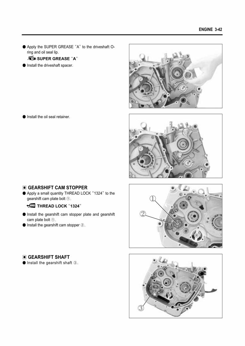
ENGINE 3-42
● Apply the SUPER GREASE “A”to the driveshaft O-ring and oil seal lip.
SUPER GREASE “A”
● Install the driveshaft spacer.
● Install the oil seal retainer.
▣ GEARSHIFT CAM STOPPER● Apply a small quantity THREAD LOCK “1324”to the
gearshift cam plate bolt ①.
● Install the gearshift cam stopper plate and gearshiftcam plate bolt ①.
● Install the gearshift cam stopper ②.
▣ GEARSHIFT SHAFT● Install the gearshift shaft ③.
THREAD LOCK “1324”
①
②
③

3-43 ENGINE
◉ OIL PUMP● Before installing the oil pump, apply the engine oil to
the contact face of case, outer rotor, inner rotor andshaft.
● Apply a small quantity THREAD LOCK “1324”to theoil pump securing screws.
● Tighten the oil pump securing screws.● Install the oil pump shim and pin.
THREAD LOCK “1324”
● Put in the oil pump driven gear, and install the circlip.
CAUTIONAfter the cam driven gear, cam guide, gearshiftshaft and neutral cam stopper have been fitted, confirm that gear change is normal while turningthe countshaft and driveshaft. If gear change is not obtained, it means that assembly of gears or installation of gear shifting fork is incorrect. In this case, disassemble and trace the mistake.
CAUTIONWhen installing the oil pump to the crankcase,turn the pump gear and check that rotation issmooth by the hand.
11sstt
NN
22nndd
33rrdd
44tthh
55tthh

ENGINE 3-44
Cam chain tensioner bolt : 8~12 N∙m (0.8~1.2 kg∙m)
◉ CAM CHAIN TENSIONER● Install the washer and cam chain tensioner ②,
tighten the cam chain tensioner bolt ①.
● Install the cam chain ③.
◉ PRIMARY DRIVE GEAR● Install the primary drive gear and NO.2 gear to the
crankshaft, put the key to the key groove.
CAUTIONWhen installing the NO.2 gear, install so that themark on the gear align the key groove as shownin figure.
● With the crankshaft held immovable using specialtool, install the water pump drive gear ④ and primarydrive gear nut ⑤.
Conrod holder : 09910-20115
Primary drive gear nut : 40~60 N∙m (4.0~6.0 kg∙m)
CAUTION
Pay attention to the each washer to lower end ofthe water pump drive gear and primary drive gearnut in times of assemblage.
NOTEThe primary drive gear nut has left-hand thread.
Align the key grooveand mark.
NO.2 Gear
① ②
③
④
⑤

3-45 ENGINE
◉ PRIMARY DRIVEN GEAR
● Install the primary driven gear assembly.
◉ CLUTCH● Install the clutch sleeve hub ①, lock washer ②.
NOTEApply the engine oil to the inside face of primarydriven gear bearing.
● Bend the lock washer securely.
● Install the clutch sleeve hub nut, and tighten it to thespecified torque using the special tool.
● Install the clutch drive plate NO. 2 �.
● Install the spring washer seat � and spring washer� onto the clutch sleeve hub correctly.
● Install the clutch driven plates � and drive platesNO. 1 � one by one into the clutch sleeve hub in theprescribed order.
Clutch sleeve hub holder : 09920-53710
Clutch sleeve hub nut : 40~60 N∙m (4.0~6.0 kg∙m)
②
①
��

ENGINE 3-46
● Install the clutch release rack ①, bearing ② andwasher ③.
● Install the clutch pressure plate ④, retainer, clutchsprings and clutch spring mounting bolts.
● Hold the primary drive gear nut and tighten the clutchspring mounting bolts in a crisscross pattern.
▣ CLUTCH COVER● Install the two dowel pins ⑤ and new gasket ⑥.
● Apply engine oil to each gears, bearings and clutchplates.
NOTEMake sure that the clutch pressure plate isinstalled correctly.
� �
�
Directionof inside
� NO. 2 Drive plate � NO. 1 Drive plate
①②③
④
⑤
⑤
⑥

3-47 ENGINE
● Install the clutch cover, and tighten the clutch coverbolts securely.
● Install the clutch release arm as following :① Turn the clutch release shaft toward(This time,
mark on the shaft align outside contact line thestopper screw) the right.
② Install that the release camshaft notch mark alignmatching mark of the crankcase as shown in theright figure.
THREAD LOCK “1324”
◉ STATOR● Apply a small quantity of THREAD LOCK “1324”to
the threaded parts of screws.
THREAD LOCK “1324”
◉ STARTER CLUTCH● When installing the starter clutch and rotor, apply the
THREAD LOCK “1324”to the bolts and tighten tothe specified torque.
Engine oil drain plug : 21 N∙m (2.1 kg∙m)
◉ OIL DRAIN PLUG● Tighten the oil drain plug to the specified torque.
Starter clutch bolt : 23~28 N∙m (2.3~2.8 kg∙m)
Crankcasematching mark
Clutch release arm
Clutch releasearm bolt
Stopper screw
Release camshaftnotch mark

ENGINE 3-48
THREAD LOCK “1324”
◉ MAGNETO ROTOR● Fit the key into the key slot on the crankshaft.● With the magneto rotor, install the starter clutch on
the crankshaft.● Apply a small quantity of THREAD LOCK “1324”to
the threaded parts of crankshaft.
● Tighten the magneto rotor bolt to the specifiedtorque.
◉ STARTER IDLE GEAR ANDMOTOR
● Install the starter idle gear, shaft.
● Install the starter motor.
Conrod holder : 09910-20115
Magneto rotor bolt : 110~170 N∙m (11.0~17.0 kg∙m)

3-49 ENGINE
◉ MAGNETO COVER● Install the new gasket and dowel pin.● Apply oil to the each gear, bearing and starter clutch.
Magneto cover bolt : 10 N∙m (1.0 kg∙m)
● Install the magneto cover and tighten the magnetocover bolts.
● When all the piston rings have been assembled,check that each can turn smoothly.
● To minimize compression and oil leaks, locate eachpiston ring end gap in the position as shown in theright illustration
● Install the spacer ①.
● Install the upper and lower side rail ②.
◉ PISTON RING● First, install the piston ring in order of oil ring, 2nd
ring and 1st ring at the front cylinder.
◉ PISTON● Apply the MOLY PASTE to the piston pin.
● When installing the piston, turn the mark � on thepiston head to exhaust side.
● After the piston pin has been inserted through theconrod, install the circlip ③.
MOLY PASTE
CAUTIONBe careful not to cause scratch on the pistonwhen inserting the piston ring to the piston.Also, do not expand the piston ring more thannecessary as the ring can break.
CAUTIONReplace the circlip with a new one.Place a piece of rag under the piston when installing the circlip to prevent it from fallinginto the crankcase.
② INCORRECT
CORRECT②
①
EX
②②
①IN
③�

ENGINE 3-50
BOND “1215”
◉ CYLINDER● Apply BOND “1215”to the parting line of crankcase.
◉ VALVE AND SPRING● Insert the valve, with their stems coated with MOLY
PASTE.
Apply the oil to the lip of the stem seal.● The narrow pitch side of each spring face to the head
when the valve spring install. The pitch of insidespring and outside spring is changed. The pitch ofspring is decreased from the upper side to the lowerside.
◉ CYLINDER HEAD● Put the valve spring and retainer and install the valve
cotter with compressed the spring by using the valvespring compressor.
● Place the dowel pin ① and new gasket on thecrankcase.
● Apply the engine oil to the conrod small end, pistonand the piston rings.
● Coat the cylinder wall with oil.● Install the cylinder and tighten the cylinder base nuts.
Cylinder base nut : 7~11 N∙m (0.7~1.1 kg∙m)
This cylinder is different from the front and rear.
Valve spring compressor : 09916-14510Valve spring compressor attachment
: 09916-14520
● Fit the cylinder head and tighten the six cylinder headbolts diagonally.
Cylinder head bolt (M6): 8~12 N∙m (0.8~1.2 kg∙m)
Cylinder head bolt (M10): 40~45 N∙m (4.0~4.5 kg∙m)
CAUTIONAfter installing the valve cotter, tap the valvestem end by using the plastic hammer at 2~3times for assembly of the valve and cotter.
CAUTIONMake sure to replace the gasket with a new one.
MOLY PASTE
Head direction
Broad pitch part
Narrow pitch part
↓
↓
↓
↓
①

3-51 ENGINE
● Tighten the cylinder head base bolt.
Cylinder head base bolt: 8~12 N∙m (0.8~1.2 kg∙m)
● Install the tappet and shim.
● Fit the chain guide.
CAUTIONWith the tappet fitted, it should be replaced if itdoesn’t turn smoothly by the hand.
CAUTIONThe tappet and shim should be installed at theoriginal position when removed.If otherwise, it is difficult to adjust the valve clear-ance.
CAUTIONPay caution to prevent the cam chain from drop-ping into the crankcase.
Tappet
Shim
[ Front Cylinder ]
[ Rear Cylinder ]

ENGINE 3-52
◉ CAMSHAFT ASSEMBLY● Distinguish the “EX”mark for the exhaust camshaft,
the “IN”mark for the intake camshaft.
● With pulling up the camshaft drive chain, align the “|F”mark of magneto rotor into the punching mark ofmagneto cover to turn the crankshaft.(Front cylinder)
● The front cylinder head install first the exhaustcamshaft, following the intake camshaft.The rear cylinder head install first the intake as thecam chain tensioner adjuster exist exhaust side.
CAUTIONIf turn the crankshaft without pulling up the camshaftdrive chain, the chain may be fallen off between thecrankcase and cam chain drive sprocket.
CAUTION
When adjusting the rear cylinder, align the “|R”
mark of magneto rotor into turn counter-clock-wise 285�at the position of front cylinder.
INEX
EX
IN

3-53 ENGINE
● Gear into the chain at the “3”arrow of intake sprock-et that count the 16th of chain roller pin from theroller pin on the “2”arrow of exhaust sprocket to theintake camshaft.
● Install the “3”arrow punching mark of intakecamshaft sprocket with the surface of cylinder headvertically.
● The “1F”arrow of exhaust camshaft sprocket shouldbe toward the outside and aligned with the plane ofFRONT cylinder head.At that time, the “2”arrow of exhaust camshaftsprocket should be in a vertical position to the planeof cylinder head when exhaust camshaft sprocketwas geared into cam chain.
● The “1R”arrow of intake camshaft sprocket shouldbe toward the outside and aligned with the plane ofREAR cylinder head. At that time, the “2”arrow ofintake camshaft sprocket should be in a vertical posi-tion to the plane of cylinder head when the intakecamshaft sprocket was geared into the cam chain.
CAUTIONThe REAR cylinder gear into that count the 16thof chain rol ler pin from the “2”arrow ofintake sprocket to the “3”arrow of exhaustsprocket.
33
33
22
22
11FF
16pinExhaust Intake
33 22
11RR

ENGINE 3-54
CAUTIONThe cam chain is installed to the all of three sprocket.Be sure to lie the crankshaft until the two holder and cam chain tensioner adjuster are installed completely.
NOTEThe camshaft housing should be installed in the same manner with the front engine.
16 Pin16 Link 1 Link
Rotation Direction
Exhaust Intake
[Rear cylinder]
Exhaust Intake
Rotation Direction1 Link 16 Link
[Front cylinder]

3-55 ENGINE
Camshaft housing bolt : 12 N∙m (1.2 kg∙m)
● Put the intake or exhaust camshaft housing to thecylinder head upper surface.
● Tighten the camshaft housing bolt with the specifiedtorque diagonally.
● If turn the lock shaft handle in clockwise ( )direction, the pushrod is inserted in.Turn the mechanical spring continually until the han-dle is turned to the end.
● Fix the adjuster into the cylinder block.
CAUTIONThe camshaft housing bolt is made of the specialmaterial.This bolt is superior at the degree of hardnessmore than the different high tension bolt.Pay special caution that the different type of boltshould not be used.This bolt head is punched the “9”mark.
● Get out the pushrod for the front to turn the lock shafthandle in counter-clockwise ( ).
�
Lock shaft handle

ENGINE 3-56
Standard
0.1 ~ 0.2 mm
(0.004 ~ 0.008 in)
0.28 ~ 0.32 mm
(0.011 ~ 0.013 in)
Valve clearance
IN.
EX.
● Apply BOND “1215”to the surface of cylinder headcover packing block.
BOND “1215”
● Tighten the cylinder head cover bolts with the speci-fied torque.
Cylinder head cover bolt : 12~16 N∙m (1.2~1.6 kg∙m)
● Turn the crankshaft about 10 times counter-clock-wise ( ) on the basis of the magneto rotor.
● If the valve clearance is within standard after mea-sured the valve clearance, begin the next operation.If it is out of stanadard, adjust the valve clearancewithin standard limit after disassembled the camshaftand replaced the proper shim.
● Adjust the valve clearance of rear cylinder with thesame manner of the front cylinder.(Refer to page 2-4)
CAUTIONIf you don’’t turn the crankshaft about 10 timesbefore measured the valve clearance, there is nomeaning in valve clearance.
◉ SPARK PLUG● Install the spark plug. (Refer to page 2-7)

● Install the rear cylinder head and cylinder with thesame manner which installed the front cylinder headand cylinder.
SUPER GREASE “A”
◉ GEAR POSITION SWITCH● Install the spring ③ and contact ④.● Apply SUPER GREASE “A”to the O-ring and install
the gear position switch.
◉ THERMOSTAT● Install the thermostat case ① along with the hose ②.
3-57 ENGINE
NOTEThermostat reassembly
: Refer to page 5-9
Front Cylinder
Rear Cylinder
①
③
④
②

CAUTIONGasoline must be handled carefully in an area well ventilated and away from fire or sparks.
FUEL SYSTEM
FUEL TANK / FUEL COCK …………………………………………… 4- 1
FUEL PUMP ………………………………………………………………… 4- 2
CARBURETOR……………………………………………………………… 4- 3
CONTENTS
4

FUEL TANK / FUEL COCK
◉ REMOVAL
● Remove the seat. (Refer to page 7-1) ● Remove the fuel tank mounting bolts and fuel tank
bracket mounting bolt.● Disconnect the fuel hose ① and remove the fuel
tank.
● Remove the fuel cock.
◉ INSPECTION▣ FUEL COCKIf the fuel filter is dirty with sediment or rust, fuel will notflow smoothly and loss of engine power may result.Clean the fuel filter.Also check the fuel cock for cracks.
WARNINGGasoline is very explosive. Extreme care must be taken.
4-1 FUEL SYSTEM
①

● Disconnect the fuel hose ③, connect the suitablehose and insert the free end of the hose into a recep-tacle.
Check the fuel flow when starting the engine for a fewseconds by pressing the starter switch.If the fuel flow is not found, check the fuel cock. (Referto page 4-1)If the fuel cock and hoses are not fault, replace the fuel pump.
◉ INSPECTION
◉ REASSEMBLYCarry out the assembly procedure in the reverse orderof disassembly.● Tighten the fuel pump mounting bolts.● Connect the fuel hoses ③, ④ and vacuum hose ⑤
securely.
FUEL HOSE ROUTING :Fuel hose ③ (To carburetor)Fuel hose ④ (To fuel cock)Vacuum hose ⑤ (To carburetor vacuum pipe).
FUEL PUMP
◉ REMOVAL● Remove the seat and fuel tank. ● Disconnect the fuel hoses ③, ④ and vacuum hose
⑤.● Remove the fuel pump mounting bolts.
WARNINGGasolin is very explosive. Extreme care must be taken.
FUEL SYSTEM 4-2
◉ REMOUNTINGRemount the fuel tank and fuel cock in the reverse orderof removal.
CAUTION●● Gaskets ①① and ②② must be replaced with new
ones to prevent fuel leakage.●● Tighten the fuel cock bolts evenly.
①
②
③④
⑤
④
③
⑤
③

CARBURETOR
4-3 FUEL SYSTEM

FUEL SYSTEM 4-4
◉ REMOVAL● Remove the fuel tank. (Refer to page 4-1)● Remove the fuel hose.
◉ LOCATION OF CARBURE-TOR I.D.NO.
The carburetor I.D. is stamped on the location on thecarburetor as shown in the right photo.
● Remove the throttle cables ① and choke cable.
● Loosen the clamp screw and remove the carburetor.
◉ DISASSEMBLY● Remove the diaphragm cover ②.
②
①

● Remove the jet needle cap ③, spring ④, retainer⑤, and jet needle ⑥.
● Remove the float chamber body ⑦.
● Remove the float assembly ⑨ along with the needlevalve ⑧ by removing the pin.
● Remove the spring ① along with diaphragm ②.
4-5 FUEL SYSTEM
②
①
⑦
⑧
⑨
③ ④⑤ ⑥
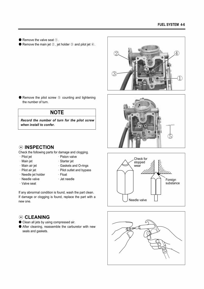
● Remove the valve seat ①.
● Remove the main jet ②, jet holder ③ and pilot jet ④.
FUEL SYSTEM 4-6
● Remove the pilot screw ⑤ counting and tighteningthe number of turn.
◉ INSPECTIONCheck the following parts for damage and clogging.∙Pilot jet ∙Piston valve∙Main jet ∙Starter jet∙Main air jet ∙Gaskets and O-rings∙Pilot air jet ∙Pilot outlet and bypass∙Needle jet holder ∙Float∙Needle valve ∙Jet needle∙Valve seat
If any abnormal condition is found, wash the part clean. If damage or clogging is found, replace the part with anew one.
◉ CLEANING● Clean all jets by using compressed air.● After cleaning, reassemble the carburetor with new
seals and gaskets.
NOTERecord the number of turn for the pilot screwwhen install to confer.
Needle valve
Check forstoppedwear
Foreignsubstance
③
② ④
①
⑤

◉ FLOAT HEIGHT ADJUSTMENTTo check the float height, turn the carburetor upsidedown. Measure the float height � while the float arm isjust contacting the needle valve using vernier calipers.
Float height �� 7 mm (0.28 in)
Vernier calipers : 09900-20101
● Fit the seal rings securely to the float chamber andinstall the float chamber to the carburetor body.
● Install the three screws ②.
● Bend the float arm ① as necessary to bring theheight to the specified level.
● After adjustment, check the float height and the fuellevel again.
◉ REASSEMBLYCarburetor reassembly can be performed in the reverseorder of disassembly. When reassembling, carefullyobserve the following instructions.
● After cleaning, reinstall the pilot screw to the originalnumber of turn that is recorded during disassem-bly.
4-7 FUEL SYSTEM
�
①
②

FUEL SYSTEM 4-8
● Af te r the assembly and ins ta l la t ion on theengine have been completed, perform the follow-ing adjusment.Throttle cable adjustment. (Refer to page 2-9)Idle speed adjustment. (Refer to page 2-9)
● Align the hole ① of the diaphragm with passage wayon the carburetor body.
● Install the two screws ② and diaphragm cover ③.
CAUTIONNever adjust “CO adjust screw”� of the carbure-tor. If adjust at discretion, have a bad influence upon output of the engine as the two carburetor is disharmonious.
�
③ ②
①

ENGINE COOLANT ……………………………………………………… 5- 1
COOLING CIRCUIT ……………………………………………………… 5- 2
RADIATOR…………………………………………………………………… 5- 2
COOLING FAN……………………………………………………………… 5- 5
COOLING FAN THERMO-SWITCH ………………………………… 5- 6
ENGINE COOLANT TEMPERATURE SENSOR………………… 5- 7
THERMOSTAT……………………………………………………………… 5- 8
WATER PUMP ……………………………………………………………… 5-10
COOLING SYSTEM
5
CONTENTS
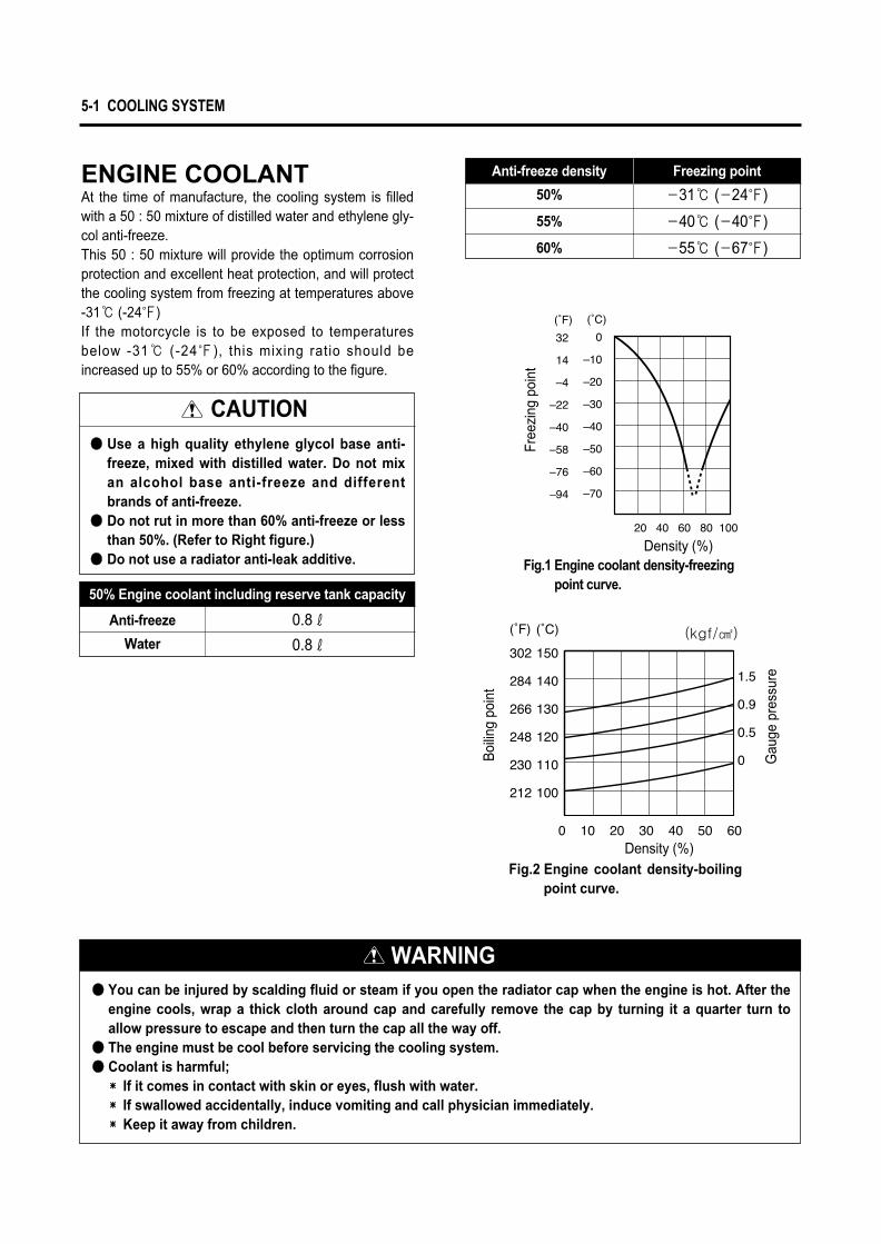
ENGINE COOLANTAt the time of manufacture, the cooling system is filledwith a 50 : 50 mixture of distilled water and ethylene gly-col anti-freeze.This 50 : 50 mixture will provide the optimum corrosionprotection and excellent heat protection, and will protectthe cooling system from freezing at temperatures above-31℃ (-24℉)If the motorcycle is to be exposed to temperaturesbelow -31℃ (-24℉), this mixing ratio should beincreased up to 55% or 60% according to the figure.
5-1 COOLING SYSTEM
CAUTION●● Use a high quality ethylene glycol base anti-
freeze, mixed with distilled water. Do not mixan alcohol base anti-freeze and differentbrands of anti-freeze.
●● Do not rut in more than 60% anti-freeze or lessthan 50%. (Refer to Right figure.)
●● Do not use a radiator anti-leak additive.
50% Engine coolant including reserve tank capacity
Anti-freeze
Water
0.8ℓ
0.8ℓ
WARNING●● You can be injured by scalding fluid or steam if you open the radiator cap when the engine is hot. After the
engine cools, wrap a thick cloth around cap and carefully remove the cap by turning it a quarter turn toallow pressure to escape and then turn the cap all the way off.
●● The engine must be cool before servicing the cooling system.●● Coolant is harmful;�� If it comes in contact with skin or eyes, flush with water.�� If swallowed accidentally, induce vomiting and call physician immediately.�� Keep it away from children.
Free
zing
poi
nt
Boi
ling
poin
t
Gau
ge p
ress
ure
Density (%)Fig.1 Engine coolant density-freezing
point curve.
Density (%)Fig.2 Engine coolant density-boiling
point curve.
(kgf/㎠)
Anti-freeze density Freezing point
50%
55%
60%
-31℃ (-24℉)
-40℃ (-40℉)
-55℃ (-67℉)

COOLING SYSTEM 5-2
COOLING CIRCUIT
RADIATOR◉ REMOVAL● Drain engine coolant. (Refer to page 2-24)●With the two mounting bolts ② removed, remove the
right front side cover ①.● Remove the radiator cap bolt ③.
● Remove the radiator cover by the four mountingbolts.
● Disconnect the radiator outlet hose ④.
RESERVE TANK
RADIATOR
THERMOSTAT
FRONT CYLINDER HEAD
FRONT CYLINDER
WATER PUMP
REAR CYLINDER
REAR CYLINDER HEAD
④
③
①
②

5-3 COOLING SYSTEM
◉ INSPECTION AND CLEANINGRoad dirt or trash stuck to the fins must be removed.Use of compressed air is recommended for this clean-ing.
● Remove the radiator by the mounting bolts.
● Disconnect the cooling fan thermo-switch lead wirecoupler ①.
● Disconnect the radiator inlet hose ②.
● Disconnect reserve tank hose ③.● Disconnect the cooling fan motor lead wire coupler④.
①
②
④③

◉ INSTALLATIONThe radiator reassembly can be performed in thereverse order of disassembly procedures.However, the following points must be observed in thereassembly operation.● Install the radiator with the specified torque.
Radiator mounting bolt : 8~12 N∙∙m (0.8~1.2 kg∙∙m)
� Pour engine coolant Refer to page 2-24� Bleed air from the cooling circuit Refer to page 2-25
COOLING SYSTEM 5-4
Fins bent down or dented can be repaired by straighten-ing them with the blade of a small screwdriver.
◉ INSPECTION OF WATERHOSE
Any water hose found in a cracked condition or flattenedor water leaked must be replaced.Any leakage from the connecting section should be cor-rected by proper tightening.

The voltmeter is for making sure that the batteryapplies 12 volts to the motor. With the motor withelectric motor fan running at full speed, the amme-ter should be indicating not more than 5 amperes.If the fan motor does not turn, replace the motorassembly with a new one.
◉ REMOVAL● Drain engine coolant. (Refer to page 2-24)● Remove the radiator cover.● Remove the radiator. (Refer to page 5-2)● Disconnect the cooling fan thermo-switch ③. ● Remove the cooling fan.
◉ INSTALLATION● Install the cooling fan to the radiator.
Cooling fan mounting bolt : 8~12 N∙∙m (0.8~1.2 kg∙∙m)
Cooling fan motor mounting bolt : 8 N∙∙m (0.8 kg∙∙m)
● Install the radiator.● Route the radiator hoses properly.● Pour engine coolant. (Refer to page 2-24)● Bleed air from the cooling circuit.
(Refer to page 2-25)● Install the radiator cover.
COOLING FAN◉ INSPECTION● Remove the radiator cover. (Refer to page 5-2)● Disconnect the cooling fan motor lead wire coupler ①
and its thermo-switch lead wire coupler ②.Test the cooling fan motor for load current with anammeter connected as shown in the illustration.
5-5 COOLING SYSTEM
NOTEWhen making above test, it is not necessary toremove the cooling fan.
③
①
②
Fan motor Ammeter
Battery
B
BrW

COOLING FAN THERMO-SWITCH◉ REMOVAL● Drain engine coolant. (Refer to page 2-24)● Remove the radiator cover. (Refer to page 5-2)● Disconnect the cooling fan thermo-switch lead wire
coupler ①.● Remove the cooling fan thermo-switch ②.
◉ INSPECTION● Check the thermo-switch closing or opening tempera-
tures by testing it at the bench as shown in the figure.Connect the thermo-switch ③ to a circuit tester andplace it in the OIL contained in a pan, which is placedon a stove.
● Heat the oil to raise its temperature slowly and readthe column thermometer ④ when the switch closes
Multi circuit tester set : 09900-25008
◉ INSTALLATION● Install a new O-ring ⑤ and apply engine coolant to
the O-ring.● Tighten the cooling fan thermo-switch to the specified
torque.Cooling fan thermo-switch
: 13 N∙∙m (1.3 kg∙∙m)● Pour engine coolant. (Refer to page 2-24)● Bleed air from the cooling circuit. (Refer to page 2-25)● Install the radiator cover.
COOLING SYSTEM 5-6
Cooling fan thermo-switch operating temperature
Standard
ON →→ OFF
OFF →→ ON
Over 88℃℃
(190℉℉)
Approx. 95℃℃
(203℉℉)
CAUTION
●● Take special care when handling the thermo-switch.It may cause damage if it gets a sharp impact.
●● Do not contact the cooling fan thermo-switch③③ and the column thermometer ④④ with a pan.
Oil
③④
⑤
①②
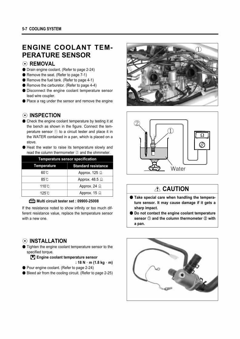
ENGINE COOLANT TEM-PERATURE SENSOR◉ REMOVAL● Drain engine coolant. (Refer to page 2-24)● Remove the seat. (Refer to page 7-1)● Remove the fuel tank. (Refer to page 4-1)● Remove the carburetor. (Refer to page 4-4)● Disconnect the engine coolant temperature sensor
lead wire coupler.● Place a rag under the sensor and remove the engine
◉ INSPECTION● Check the engine coolant temperature by testing it at
the bench as shown in the figure. Connect the tem-perature sensor ① to a circuit tester and place it inthe WATER contained in a pan, which is placed on astove.
● Heat the water to raise its temperature slowly andread the column thermometer ② and the ohmmeter.
5-7 COOLING SYSTEM
Temperature sensor specification
Temperature
60℃
85℃
110℃
125℃
Standard resistance
Approx. 125 Ϊ
Approx. 48.5 Ϊ
Approx. 24 Ϊ
Approx. 15 Ϊ
If the resistance noted to show infinity or too much dif-ferent resistance value, replace the temperature sensorwith a new one.
Multi circuit tester set : 09900-25008
CAUTION●● Take special care when handling the tempera-
ture sensor. It may cause damage if it gets asharp impact.
●● Do not contact the engine coolant temperaturesensor ①① and the column thermometer ②② witha pan.
◉ INSTALLATION● Tighten the engine coolant temperature sensor to the
specified torque.Engine coolant temperature sensor
: 18 N∙∙m (1.8 kg∙∙m)● Pour engine coolant. (Refer to page 2-24)● Bleed air from the cooling circuit. (Refer to page 2-25)
Water
①②
①

THERMOSTAT◉ REMOVAL● Drain engine coolant. (Refer to page 2-24)● Place a rag under the thermostat case.● Remove the thermostat case cap.
● Remove the thermostat ①.
◉ INSPECTIONInspect the thermostat pellet for signs of cracking.Test the thermostat at the bench for control action, inthe follwing manner.● Pass a string between flange, as shown in the photo-
graph.● Immerse the thermostat in the WATER contained in a
beaker, as shown in the illustration. Note that theimmersed thermostat is in suspension. Heat thewater by placing the beaker on a stove ① andobserve the rising temperature on a thermometer ②.
● Read the thermometer just when opening the ther-mostat. This reading, which is the temperature levelat which the thermostat valve begins to open, shouldbe within the standard value.
COOLING SYSTEM 5-8
Thermostat valve operation temperature
Valve opening
Valve full open
Valve closing
Standard
88℃ (190℉)
100℃ (212℉)
83℃ (181℉)Water
①
②
①

●● Keep on heating the water to raise its temperature.●● Just when the water temperature reaches specified
value, the thermostat valve should have lifted by atleast 8.0 mm (0.31 in).
●● A thermostat failing to satisfy either of the tworequirements, start-to-open temperature and valvelift, must be replaced.
◉ INSTALLTION● Apply engine coolant to the rubber seal on the ther-
mostat.● Install the thermostat.
● Install the thermostat case cap ②.
● Tighten the thermostat case bolts to the specifiedtorque.
Thermostat case bolt : 10 N∙∙m (1.0 kg∙∙m)● Pour engine coolant. (Refer to page 2-24)● Bleed air from the cooling circuit.
(Refer to page 2-25)
Standard
Over 8.0mm at 100℃
(Over 0.31in at 212℉)
Thermostat valve lift ��
5-9 COOLING SYSTEM
NOTEThe jiggle valve ①① of the thermostat facesupside.
NOTEThe rib of the thermostat case cap ②② shouldbe faced upward.
�
①
②
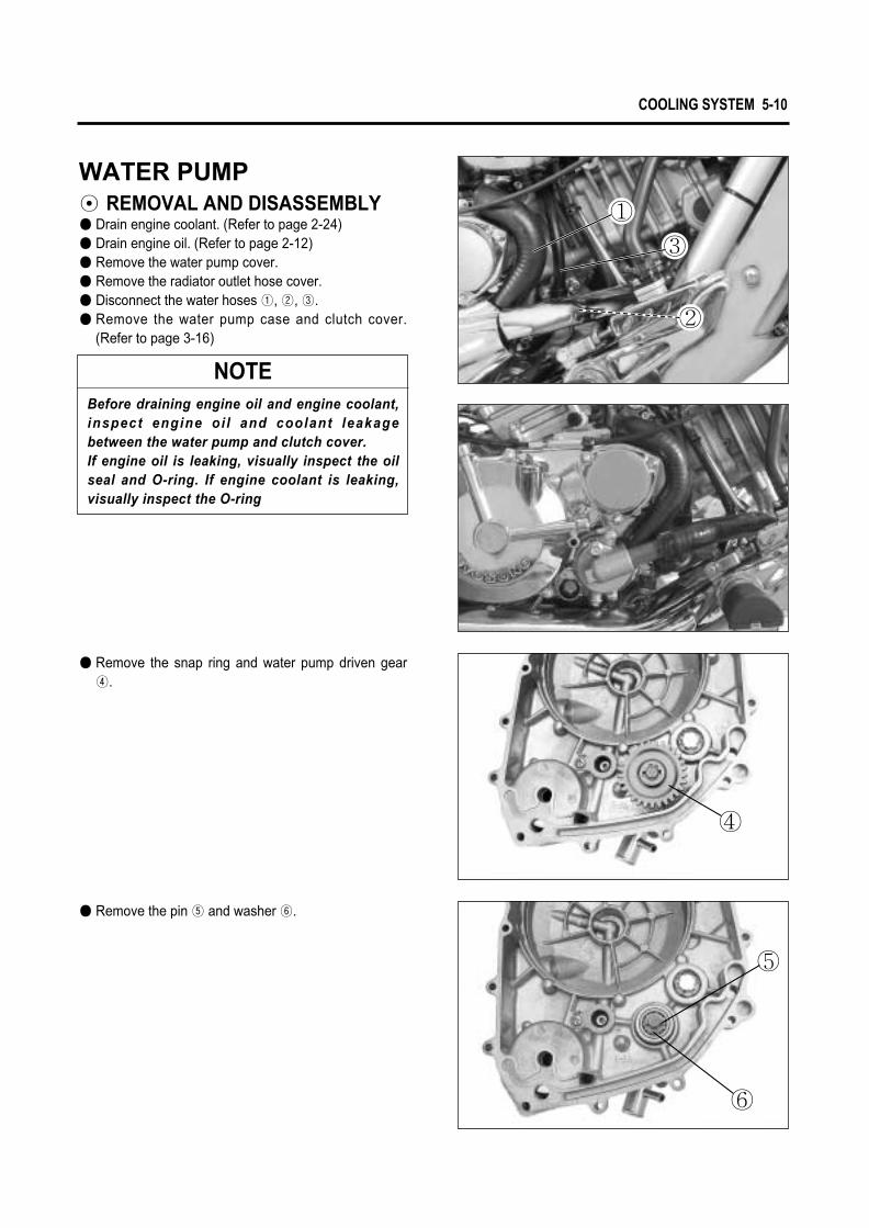
COOLING SYSTEM 5-10
WATER PUMP◉ REMOVAL AND DISASSEMBLY● Drain engine coolant. (Refer to page 2-24)● Drain engine oil. (Refer to page 2-12)● Remove the water pump cover.● Remove the radiator outlet hose cover.● Disconnect the water hoses ①, ②, ③.● Remove the water pump case and clutch cover.
(Refer to page 3-16)
● Remove the snap ring and water pump driven gear④.
● Remove the pin ⑤ and washer ⑥.
NOTEBefore draining engine oil and engine coolant,inspect engine oi l and coolant leakagebetween the water pump and clutch cover.If engine oil is leaking, visually inspect the oilseal and O-ring. If engine coolant is leaking,visually inspect the O-ring
④
⑤
⑥
①
③
②

● Remove the water pump ① f rom the c lutchcover.
● Remove the O-rings ②.
● Remove the E-ring ③ from the impeller shaft.
● Remove the impeller ④ from the other side.
5-11 COOLING SYSTEM
①
②
③
④

COOLING SYSTEM 5-12
● Remove the bearing.
◉ INSPECTION▣ BEARINGInspect the play of the bearing by hand while it is in thewater pump case.Rotate the inner race by hand to inspect abnormalnoise and smooth rotation.Replace the bearing if there is anything unusual.
▣ BEARING CASEVisually inspect the bearing case for damage.Replace the water pump body if necessary.
◉ REASSEMBLY AND INSTAL-LATION
● Install the bearing.
NOTEIf there is no abnormal noise, bearing removalis not necessary.
NOTEThe stamped mark on the bearing faces to thecrankcase side.

● Apply engine coolant to the O-ring ②.● Install a new O-ring.
● Connect the water hoses.● Install the radiator outlet hose cover.● Install the water pump cover.● Pour engine coolant. (Refer to page 2-24)● Pour engine oil. (Refer to page 2-12)
● Apply SUPER GREASE “A”to the impeller shaft.SUPER GREASE “A”
● Install the impeller to the water pump body.
● Fix the impeller shaft with the E-ring ①.● Fill the bearing with engine oil until engine oil comes
out from the hole of the bearing housing.
5-13 COOLING SYSTEM
CAUTIONUse a new O-ring to prevent engine coolantleakge.
①
②

LOCATION OF ELECTRICAL COMPONENTS ………………… 6- 1
IGNITION SYSTEM………………………………………………………… 6- 3
CHARGING SYSTEM …………………………………………………… 6- 7
STARTER SYSTEM AND SIDE STAND IGNITION INTERLOCK SYSTEM ………………… 6-11
SWITCHES …………………………………………………………………… 6-15
LAMP…………………………………………………………………………… 6-16
BATTERY …………………………………………………………………… 6-18
ELECTRICAL SYSTEM
6
CONTENTS

LOCATION OF ELECTRICAL COMPONENTS
6-1 ELECTRICAL SYSTEM
⑤ Engine coolant temperature sensor⑥ Thermostat
⑦ Front brake lamp switch
⑧ Side stand switch ⑨ Rear brake lamp switch ⑩ Starter motor
① Battery② Head lamp relay③ Side stand relay④ Cooling fan motor relay
①
④ ⑤ ⑦
⑥
③
②
⑧⑧ ⑨
⑩

ELECTRICAL SYSTEM 6-2
⑫ Regulator / Rectifier⑬ Turn signal relay
⑭ Cooling fan motor⑮ Cooling fan thermo-switch
⑪ Ignition coil (NO.1 & NO.2)
� Magneto � Gear position switch� Fuses� Igniter
⑪
�
�
�
�
⑫ ⑬
⑭
⑮

Magneto
�
�
Igniter
Ft. I
GNI
TIO
N C
OIL
Rr.
IGNI
TION
CO
IL
IGNI
TER
IG. S/WENGINE STOP S/W
FUSEREGREC
BATTERY12V 12Ah
G
L
Y
Y
Y
Ignition coil & Spark plug
IGNITION SYSTEMis started as the battery discharged ignition system without a contact point. The battery ignition system is
composed a rotor with four rotor tip, the igniter, the ignition coil and battery. This system ignites after get signal from igni-tion timing of pick-up with the electric energy of this battery and occur the 1st electric current. Therefore, a high voltagecurrent is induced in the secondary winding of the ignition coil and results in strong spark between spark plug gap.
6-3 ELECTRICAL SYSTEM
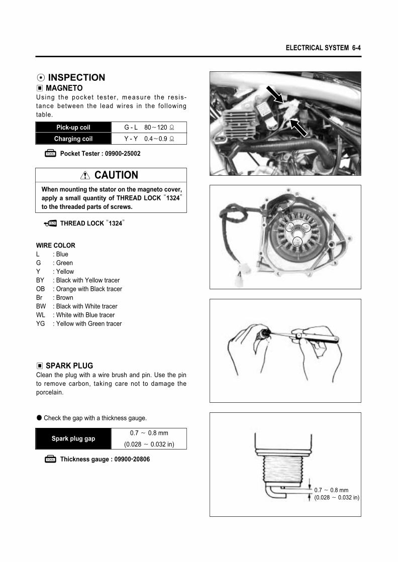
Pocket Tester : 09900-25002
THREAD LOCK “1324”
G - L 80�120 Ϊ
Y - Y 0.4�0.9 Ϊ
Pick-up coil
Charging coil
◉ INSPECTION▣ MAGNETOUsing the pocke t tes te r , measu re the res is -tance between the lead wires in the fol lowingtable.
CAUTIONWhen mounting the stator on the magneto cover, apply a small quantity of THREAD LOCK “1324”
to the threaded parts of screws.
ELECTRICAL SYSTEM 6-4
WIRE COLORL : BlueG : GreenY : YellowBY : Black with Yellow tracerOB : Orange with Black tracerBr : BrownBW : Black with White tracerWL : White with Blue tracerYG : Yellow with Green tracer
▣ SPARK PLUGClean the plug with a wire brush and pin. Use the pinto remove carbon, taking care not to damage theporcelain.
● Check the gap with a thickness gauge.
Thickness gauge : 09900-20806
Spark plug gap0.7 � 0.8 mm
(0.028 � 0.032 in)
0.7 � 0.8 mm(0.028 � 0.032 in)

▣ IGNITION COIL (Checking with Pocket Tester)● A p o c k e t t e s t e r o r a n o h m m e t e r m a y b e
used, instead of the electro tester. In case, theignition coil is to be checked for continuity in bothprimary and secondary windings. Exact ohmic read-ings are not necessary, but, if the windings arein good condition, their continuity will be notedwith approximate ohmic values.
Primary
Secondary
3.5�5.5Ϊ
20�31 ㏀
Tester knob indication × 1Ϊ range
Tester knob indication × 1㏀ range
Check the attached plug cap
Ignition coil resistance
Pocket tester : 09900-25002
▣ IGNITION COIL● Pull out the spark plug.● Place it on the cylinder head after installing it at the
plug cap to obtain ground.● Push the electric starter switch to rotate the starter
motor, to have the test of sparking performance.● If spark doesn’t emit or the spark bring out the
orange color, replace the ignition coil.
CAUTIONThe ignition coil is marked the “F”for front, andthe “R”for rear.If otherwise, it may occur severe damage to theengine.
6-5 ELECTRICAL SYSTEM
B/R
GroundPlug cap
① Front cylinder ignition coil ② Rear cylinder ignition coil
②①

CAUTION� Numberical value may differ a little according
to the tester.� Please remind that there may be a defect
which can not be identified even though themeasurement by using the tester indicates alow voltage.
� The range of measurement adjust a [ X 1㏀ ]unit.
ELECTRICAL SYSTEM 6-6
▣ IGNITERUsing the pocket tester(R × 1㏀ range), measure theresistance between the terminal in the following table.
Unit : kΪ
Pocket Tester : 09900-25002
① ② ③ ④ ⑤ ⑥ ⑦ ⑧ ⑨ ⑩ ⑪ ⑫ ⑬ ⑭ ⑮ �
� TESTER PROBE
OFF OFF OFF OFF OFF OFF OFF OFF OFF OFF OFF OFF OFF OFF OFF
OFF OFF OFF OFF OFF OFF OFF OFF OFF OFF OFF OFF OFF OFF OFF
250~370 250~380 18~27 22~33 OFF 9.2~13.8 37~55 23.6~35.4 21.6~32.4 22.4~33.6 18~27 53~79 29.5~44.5 9.2~13.8 21.3~31.9
180~270 180~270 2.9~4.4 2.8~4.2 OFF 8.4~12.6 9.6~14 3.8~5.8 2.7~4.1 3~4.6 0 46~69 6.4~9.6 7.1~10.4 2.2~3.4
180~270 180~270 9.6~14 2.8~4.2 OFF 9.6~14 12.2~18.2 2.6~4 1.4~2 1.8~2.6 2.8~4.2 49~73 9.1~13.7 8.6~13 0.9~1.3
OFF OFF OFF OFF OFF OFF OFF OFF OFF OFF OFF OFF OFF OFF OFF
200~300 210~310 21.5~32.5 11.1~16.7 14.3~21.5 OFF 25.7~38.5 15.4~23 14.2~21.2 14.6~21.8 11.2~16.8 39~59 20.4~30.6 4.7~7.1 13.7~20.5
OFF OFF OFF OFF OFF OFF OFF OFF OFF OFF OFF OFF OFF OFF OFF
180~270 190~280 11~16.4 3.8~5.7 2.6~4 OFF 10.8~16.2 13.6~20.4 2.4~3.6 0.9~1.3 3.9~5.9 50.5~75.5 10.4~15.6 9.6~14 1.8~2.8
180~270 190~280 9.6~14 2.5~3.8 1.4~2 OFF 8.7~13.1 12~18 2.4~3.6 1.4~2 2.6~3.8 48~72 8.8~13.2 8~12 0.6~0.8
180~270 180~270 10~15 3.1~4.7 1.7~2.5 OFF 9.6~14 12.5~18.7 0.9~1.3 1.5~2.3 3.1~4.7 49.5~74.5 9.6~14 8.8~13.2 1~1.4
170~260 180~270 7~10.4 0 2.8~4.2 OFF 8.5~12.7 9.6~14 3.9~5.9 2.6~4 3~4.6 46.5~69.5 6.4~9.6 7.2~10.8 2.3~3.5
330~490 330~500 180~270 150~230 80~120 OFF 170~250 190~280 150~230 150~230 150~230 150~230 170~260 165~245 146~219
200~300 180~270 17.5~26.5 8.6~12.8 7.3~10.9 OFF 17.5~26.5 21.2~31.8 8.2~12.4 7~10.6 7.3~10.9 8.6~12.8 69~103 16.3~24.5 6.4~9.6
200~300 210~310 16.5~24.5 7.4~11 10~15 OFF 4.6~7 20.8~31.2 11.4~17 10~15 10.4~15.6 7.3~10.9 34~51 15.6~23.4 9.6~14
170~260 180~270 9~13.5 2.3~3.5 0.9~1.3 OFF 8.8~13.2 11.4~17 1.8~2.8 0.6~1 0.9~1.3 2.3~3.5 48~72 8.6~13 8.1~12.1
①
②
③
④
⑤
⑥
⑦
⑧
⑨
⑩
⑪
⑫
⑬
⑭
⑮
�
�TESTER
PROBE

A. C generator
A. C generator
IG. switch
IG. switch
IC
IC
Bat
tery
Bat
tery
LOA
D
LOAD
Regulator / Rectifier
Regulator / Rectifier
◉ FUNCTION OF REGULATORWhile the engine rpm is low and the generated current of the AC generator is lower than the adjusted voltageof the regulator, the regulator does not function, incidentally the generated current charges the battery directly.
CHARGING SYSTEMThe circuit of the charging system is indicated in figure, which is composed of the AC generator, regulator /rectifier unit and battery. The AC current generated from the AC generator is converted by the rectifierand is turned into the DC current, then it charges the battery.
6-7 ELECTRICAL SYSTEM

When the engine rpm become higher, the generated voltage of the AC generator also becomes higher andthe voltage between points � and � of the regulator accordingly becomes high, and when it reaches theadjusted voltage of the control unit, consequently the control unit becomes “ON”condition. On the “ON”con-dition of the control unit, signal will be sent to the SCR (Thyristor) gate probe and SCR will become “ON”
condition. Then the SCR becomes conductive to the direction from point � to point �. Namely at the state ofthis, the current generated from the AC generator gets through SCR without charging the battery and returns tothe AC generator again. At the end of this state, since the AC current generated from the AC generator flows intothe point �, reverse current tends to flow to SCR, then the circuit of SCR turns to “OFF”mode and begins tocharge the battery again. Thus these repetitions maintain charging constant voltage to the battry and protect itfrom overcharging.
A. C generator
IG. switch
Bat
tery
Regulator / Rectifier
IC
LOA
D
ELECTRICAL SYSTEM 6-8
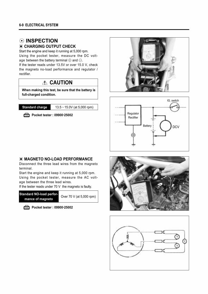
◉ INSPECTION▣ CHARGING OUTPUT CHECKStart the engine and keep it running at 5,000 rpm.Using the pocket tester, measure the DC volt-age between the battery terminal � and �.If the tester reads under 13.5V or over 15.0 V, checkthe magneto no-load performance and regulator /rectifier.
▣ MAGNETO NO-LOAD PERFORMANCEDisconnect the three lead wires from the magnetoterminal.Start the engine and keep it running at 5,000 rpm.Using the pocket tester, measure the AC volt-age between the three lead wires.If the tester reads under 70 V the magneto is faulty.
13.5�15.0V (at 5,000 rpm)Standard charge
Pocket tester : 09900-25002
Pocket tester : 09900-25002
CAUTIONWhen making this test, be sure that the battery is full-charged condition.
6-9 ELECTRICAL SYSTEM
Over 70 V (at 5,000 rpm)Standard NO-load perfor-
mance of magneto
RegulatorRectifier
DCVBattery
IG. switch

ELECTRICAL SYSTEM 6-10
▣ REGULATOR / RECTIFIER● Disconnect the coupler. ● Using the pocket tester (× 1 ㏁ range), measure the
resistance between the terminals in the followingtable.
If the resistance checked is incorrect, replace the regulator / rectifier.
①
3�4㏁
3�4㏁
1�2㏁
1�2㏁
①
②
③
④
⑤
②
3�4㏁
3�4㏁
1�2㏁
1�2㏁
③
3�4㏁
3�4㏁
1�2㏁
1�2㏁
④
1�2㏁
1�2㏁
1�2㏁
32㏀
⑤
1�2㏁
1�2㏁
1�2㏁
32㏀
�� Tester probe
Test
erpr
obe
Unit : ㏁
Pocket tester : 09900-25002
��
①
②③
④
⑤

STARTER SYSTEM AND SIDE STAND IGNITION INTER-LOCK SYSTEM◉ STARTER SYSTEM DESCRIPTIONThe starter system consists of the following components : the starter motor, starter relay, clutch lever positionswitch, igniter, side stand switch, gear position switch, starter switch, engine stop switch, ignition switch and battery.Pressing the starter switch (on the right handlebar switch) energizes the starter relay, causing the contactpoints to close, thus completing the circuit from the starter motor to the battery.
◉ SIDE STAND / IGNITION INTERLOCK SYSTEM DESCRIPTIONThis side stand / ignition interlock system prevents the motorcycle from being started with side stand down.The system is operated by an electric circuit provided between the battery and ignition coil.The circuit consists of the igniter, neutral indicator light and switches.The ignition coils will send voltage to the spark plugs depending on what gear the transmission is in andwhether the side stand is either up or down.The gear position and side stand switches work together in this system.The ignition coil work only in two situations as follows.
CLUTCH LEVERSWITCH
SIDE STANDRELAY SIDE STAND
SWITCH
NEUTRALINDICATOR
STARTSWITCH IG. SWITCH
START RELAYSTARTMOTOR
NEUTRALSWITCH
FUSE
BA
TTE
RY
SIDE STANDRELAY
BATTERY IGNITION COIL
IGNITION SWITCH
NEUTRAL SW.
DIODE
NEUTRAL INDICATOR LIGHT
SIDE STAND SW.
6-11 ELECTRICAL SYSTEM

is equipped with the side stand ignition interlock system.If the transmission is in neutral or side stand up, you can only start the engine with pulling the clutch lever.
1
2
3
4
5
●
△
●
△
△
●
●
△
●
△
△
●
△
△
●
Possible
Possible
Impossible
Impossible
Impossible
NOTE●
△
On or Up.
Off or Down
ELECTRICAL SYSTEM 6-12
BATTERY IGNITION COIL
IGNITION SWITCH
“ON”
IGNITION SW.
“ON”
NEUTRALINDICATOR LIGHT
NEUTRALSW.“ON”
DIODE
NEUTRAL SW.“OFF”
NEUTRAL INDICATOR LIGHT
DIODE
SIDE STAND SW.“UP-RIGHT POSITION”
SIDE STAND SW.SIDE STAND
“DOWN POSITION”
BATTERY IGNITION COIL
SIDE STAND RELAY“ON”
SIDE STAND RELAY“ON”
No Neutral switch Clutch lever Side stand Engine Start
▣ TRANSMISSION : Neutral - “ON”
Side stand - Down Clutch lever - Pull
▣ TRANSMISSION : Neutral - “OFF”
Side stand - UpClutch lever - Pull

▣ COMMUTATORInspect discoloration, abnormal wear or undercut � ofthe commutator.If the commutator is abnormally worn, replace thearmature.When surface is discolored, polish it with #400sand paper and clean it with dry cloth.
▣ ARMATURE COIL INSPECTIONCheck continuity between each segment.Check continuity between each segment and thearmature shaft.If there is no continuity between the segments orthere is continuity between the segment and shaft,replace the starter motor with a new one.
Pocket tester : 09900-25002
Segment
�
◉ STARTER MOTOR REMOVALAND DISASSEMBLY
● Disconnect the starter motor lead wire. ● With loosening the bolts ① , remove the starter
motor. ● Disassemble the starter motor.
◉ STARTER MOTOR INSPEC-TION
▣ CARBON BRUSHInspect abnormal wear, crack or smoothness ofthe brushes in the brush holder.If the brush has failed, replace the brush sub assy.
6-13 ELECTRICAL SYSTEM
①

● Align the mark ① on the housing with the line ②on the housing end.
SUPER GREASE “A”
● Apply SUPER GREASE “A”to the O-r ing ③and remount the starter motor.
▣ STARTER MOTOR REASSEMBLYReassemble the starter motor. Pay attention to the following points :● Reassembly the starter motor as shown in the illustration.
ELECTRICAL SYSTEM 6-14
③
① ② ①②

Pocket tester : 09900-25002
SWITCHESMeasure each switch for continuity using a tester. If any abnormality is found, replace the respective switchassemblies with new ones.
6-15 ELECTRICAL SYSTEM
R O BW BR
○ ○ON
OFF
IGNITION SWITCH
BBr
○ ○
BW
ON
OFF
HORN SWITCH
O
○ ○
WB
ON
OFF
FRONT/REAR BRAKE LAMP SWITCH
O
○ ○
Y
ON
OFF
PASS SWITCH
OB
○ ○
YR
ON
OFF
STARTER SWITCH
Sb Gr
○ ○
HAZARD SWITCH
YW
HI
LO
ON
OFF
Y W
○
○○
○
DIMMER SWITCH
Lg
L
PUSH
R
Sb B
○ ○
○ ○
TURN SIGNAL SWITCH
O
○ ○
OB
ENGINE STOP SWITCH

LAMP
◉ HEADLAMP
◉ TURN SIGNAL LAMP
◉ TAIL / BRAKE LAMP
ELECTRICAL SYSTEM 6-16

◉ COMBINATION METERRemove the combination meter. Disassemble the combination meter as shown inthe illustration.
▣ INSPECTIONUsing the pocket tester , check the cont inu i tybetween lead wires (Blue color coupler) in the follow-ing illustration.If the continuity measured incorrect, replace therespective part.
Pocket tester : 09900-25002
CAUTIONWhen making this test, it is not necessary to remove the combination meter.
6-17 ELECTRICAL SYSTEM

ELECTRICAL SYSTEM 6-18
BATTERY
◉ CAUTION OF BATTERY TREATMENTThe battery needs attention generally as it occur flammability gas.If you don’t follow the instruction in the below, there may be a explosion and severe accident.Therefore, please pay attention to the following points.
● Positively prohibit battery from contacting to short, spark or firearms.● The recharge of battery should be done in the wide place where the wind is well ventilated.
Please don’t recharge it at the sight of wind-proof.
◉ CAUTION OF BATTERY ELECTROLYTE TREATMENT● Pay attention to the battery electrolyte not to stains the chassis or the humanbody. ● If stains the chassis or the humanbody, at once wash a vast quantity of water.
When they were stained, clothes will come into being a hole or painting will take off.Consult a doctor.
● When the battery electrolyte was dropped to the surface of land, wash it with a vast quantity of water.Neutralize by hydroxide, bicarbonate of soda and so on.
◉ CAUTION OF MAINTENANCEFREE BATTERY TREATMENT
● Do not remove the aluminum tape to seal the bat-tery electrolyte filler hole until use as battery of com-plete seal type.
● Do not use it except the battery electrolyte.● Pouring into the battery electrolyte, necessarily
use the electrolyte of the specified capacity.● Do not open the sealing cap after recharging the
battery eletrolyte.
▣ FILLING ELECTROLYTE① Put the battery on even land and remove the alu-
minum tape sealing.② Remove the cap at the electrolyte container.
Aluminum tape
Filler holes
CAUTIONDo not remove the seal of the electrolytecontainer, not prick with sharp thing.

SealCap
Air bubble
6-19 ELECTRICAL SYSTEM
③ Pouring of battery electrolyteWhen insert the nozzles of the electrolyte container intothe battery’s electrolyte filler holes, holding the containerfirmly so that it does not fall.Take precaution not to allow any fluid to spill.
④ Confirmation of pourMake sure that air bubbles are coming up eachelectrolyte container, and keep this position for morethan about 20 minutes.
CAUTIONThe pouring of electrolyte may not be done ifthe electrolyte container is pushed slopely.
CAUTIONIf no air bubbles are coming up from a filler port, tap the bottom two or three times.

Insert the caps firmly
ELECTRICAL SYSTEM 6-20
⑤ Separation of electrolyte containerAfter confirming that you entered the electrolyte intobattery completely, remove the electrolyte containersfrom the battery.
⑥ Insert the capsInsert the cap into the filler holes, pressing it firmly sothat the top of the caps do not protrude above the uppersurface of the battery’s top cover.
CAUTIONDraw the empty receptacle out slowly because there may be a chance remaining electrolytevaporize.
◉ SERVICINGVisually inspect the surface of the battery container. Ifany signs of cracking or electrolyte leakage from thesides of the battery have occurred, replace the batterywith a new one. If the battery terminals are found to becoated with rust or an acidic white powdery substance,then this can be cleaned away with sandpaper.
◉ RECHARGING OPERATION● Using the pocket tester, check the battery voltage. If
the voltage reading is less than the 12.0V (DC),recharge the battery with a battery charger.
How to charge
Standard
Fast
1.2 A × 5~10 hours
6 A × 30 minutes
● After recharging, wait for more than 30 minutes andcheck the battery voltage with a pocket tester.
● If the battery voltage is less than the 12.5V, rechargethe battery again.
● If battery voltage is still less than 12.5V, afterrecharging, replace the battery with a new one.
● When the motorcycle is not used for a long period,check the battery every 1 month to prevent the bat-tery discharge.
CAUTIONWhen recharging the battery, remove the batteryfrom the motorcycle.
NOTEDo not remove the caps on the battery top whilerecharging.
CAUTIONBe careful not to permit the charging current toexceed 6A at any time.

CHASSIS
EXTERIOR PARTS………………………………………………………… 7- 1
FRAME COVER …………………………………………………………… 7- 2
SEAT TAIL COVER & SEAT TAIL COVER BRACE…………… 7- 4
FRONT WHEEL …………………………………………………………… 7- 6
FRONT BRAKE …………………………………………………………… 7-10
HANDLEBARS ……………………………………………………………… 7-17
FRONT FORK ……………………………………………………………… 7-20
STEERING …………………………………………………………………… 7-28
REAR WHEEL ……………………………………………………………… 7-31
REAR BRAKE ……………………………………………………………… 7-36
REAR SHOCK ABSORBER …………………………………………… 7-38
SWINGARM ………………………………………………………………… 7-40
CONTENTS
7

EXTERIOR PARTS
◉ FRONT FENDER● Remove the three bolts for rightside and the two bolts
for lelfside.● Remove the front fender.
◉ SEAT● To remove the seat, remove the seat mounting bolt
on the rearside of the seat.● To install the seat, slide the seat hook into the seat
hook retainer and install the seat mounting bolt.
7-1 CHASSIS

CHASSIS 7-2
FRAME COVER
◉ RIGHT DECORATION COVER● With the right decoration cover mounting screw ①
removed, remove the right decoration cover ②.
①
②

7-3 CHASSIS
◉ LEFT DECORATION COVER● With the left decoration cover mounting screw ①
removed, remove the left decoration cover ②.
◉ RIGHT FRONT SIDE COVERThe right front side cover is used to operate the radiatorcap.● With the two mounting bolts ③ removed, remove the
right front side cover ④.
◉ LEFT FRONT SIDE COVERThe left front side cover is used to inspect the fuses.● With the two mounting bolts ⑤ removed, remove the
left front side cover ⑥.
◉ RIGHT & LEFT AIR DUCTREAR COVER
● Remove the front side cover, right and left.● Remove the bolts ⑦, ⑧ inside of the cover using the
tool in the lower direction.● Remove the air duct rear cover, right and left, to take
care of the hook ⑨, ⑩.
①
②
④
⑤
⑥
③
⑨
⑦
⑧⑩CAUTIONIf the a i r duc t rear cover was removedforcedly, damage parts by reason of hook⑨⑨ , ⑩⑩ .

CHASSIS 7-4
SEAT TAIL COVER & SEAT TAIL COVER BRACE
● Remove the seat. (Refer to page 7-1)● Remove the rear shock absorber upper bolts inside
of frame, right and left.● Install the rear shock absorber upper bolts with the
frame in the outside direction temporarily.

7-5 CHASSIS
● Remove the battery ① and relay ②, ③, ④.● Disconnect the rear turn signal lamp coupler and
rear combination lamp coupler ⑤.
● Remove the two bolts ⑥.
● With the two bolts ⑦ removed, remove the seat tailcover and seat tail cover brace.
⑦
①
⑤
②
③
④
⑥

CHASSIS 7-6
FRONT WHEEL
◉ REMOVAL● Loosen the axle pinch bolt ①, right and left.● Loosen the front axle ②.● Raise the front wheel off the ground with a block
or jack.
● Remove the front wheel by removing the frontaxle ②.
CAUTIONWhen using a jack, take care not to cause scratches on the chassis.
②
①

● Remove the brake disk, right and left.
◉ INSPECTION AND DISASSEMBLY▣ TIREFor inspection of the tire : Refer to page 2-22.
▣ FRONT AXLEMeasure the front axle runout using the dial gauge.If the runout exceeds the limit, replace the front axle.
▣ WHEELMake sure that the wheel runout (axial and radial)does not exceed the service limit when checked asshown. An excessive amount of runout is usually dueto worn or loose wheel bearings and can be correctedby replacing the bearings. If bearing replacement failsto reduce the wheel.
Dial gauge : 09900-20606Magnetic stand : 09900-20701V-block : 09900-21304
Axle shaft runoutService limit
0.25 mm (0.01 in)
Wheel runout
(axial and radial)
Service limit
2.0 mm (0.08 in)
7-7 CHASSIS
[Left front brake]
[Right front brake]

▣ WHEEL BEARING REMOVAL● Remove the wheel bearing by using the special tool.
◉ REASSEMBLYReassemble the front wheel in the reverse orderof removal and disassembly.Pay attention to the following points :
Wheel bearing remover : 09941-50111
SUPER GREASE “A”
Steering race installer : 09941-34513
● Install the wheel bearings as follows by usingthe special tools.
▣ WHEEL BEARING
● Apply SUPER GREASE “A”to the wheel bearings.
▣ WHEEL BEARINGInspect the play of the wheel bearings by fingerwhile they are in the wheel. Rotate the inner race byfinger to inspect abnormal noise and smooth rotation.Replace the bearing in the following procedure if thereis anything unusual.
CAUTIONThe removed bearing should be replaced withnew ones.
CAUTIONFirst install the right wheel bearing, then installthe left wheel bearing.
CHASSIS 7-8

● Tighten the front axle bolt ① and axle pinch bolt ②to the specified torque.
Front axle bolt : 50~80 N∙m (5.0 ~8.0 kg∙m)Front axle pinch bolt
: 15~25 N∙m (1.5 ~2.5 kg∙m)
7-9 CHASSIS
▣ BRAKE DISKMake sure that the brake disk is clean and free of anygreasy matter.● Apply THREAD LOCK “1324”to the right and left
disk mounting bolts and tighten them to the speci-fied torque.
Brake disk bolt: 18~28 N∙m (1.8 ~2.8 kg∙m)
THREAD LOCK “1324”
[Left front brake]
[Right front brake]
①②

FRONT BRAKE
WARNING� Do not mix brake fluid with different brand.� Do not use a brake fluid kept in an open container or stored for long period of time.� To store brake fluid, make sure to seal the container and keep it in a safe place to be out of reach of
children.� When filling brake fluid, take care not to allow water or dirt to enter the system.� To wash the brake system parts, use brake fluid and not any other material.� Do not allow dirt and fluid to contact the brake disk or pad.
CHASSIS 7-10

◉ BRAKE FLUID REPLACEMENT● For replacing procedure of brake fluid : Refer to page 2-18
◉ BRAKE PAD REPLACEMENT● For replacing procedure of brake pad : Refer to page 2-18
◉ CALIPER DISASSEMBLY● Drain brake fluid. (Refer to page 2-18)
● Remove the right and left front brake union bolt ①and caliper mounting bolts ②.
● Remove the brake pad. (Refer to page 2-18)
● Remove the brake pad mounting bolt ③.
CAUTIONDo not allow brake fluid to contact the paint surface, plastic or rubber parts, or its chemical reaction can causediscoloration or crack.
CAUTIONTo prevent brake fluid from splashing on the parts nearby, cover the parts with cloth.
7-11 CHASSIS
[Right front brake]
[Left front brake]
③
②
①
②
①

● Using an air gun, push out the caliper piston.
● Remove the brake caliper holder ①.
WARNING� Place a rag over the piston to prevent it from
popping out and flying and keeping hand off the piston.
� Be careful of brake fluid which can possibly splash.
� Do not use high pressure air but increase the pressure gradually.
● Remove the dust seal ② and piston seal ③.
◉ CALIPER INSPECTIONInspect the caliper cylinder wall and piston surfacefor scratch, corrosion or other damages.If any abnormal condition is noted, replace the caliper.
CAUTION� Care not to cause scratch on the cylinder bore.� Do not reuse the piston seal and dust seal that
have been removed.
CHASSIS 7-12
①
② ③

● Install the brake pads. (Refer to page 2-18)
SILICONE GREASE
● Apply SILICONE GREASE to the brake caliperholder.
● Tighten the caliper mounting bolts �.● With the hose end seated to the stopper, tighten
the right and left front brake hose union bolt �.
● Fill the system with brake fluid and bleed air. (Referto page 2-19)Inspection after reassembly : Refer to page 2-17
Front brake caliper mounting bolts : 18~28 N∙m (1.8~2.8 kg∙m)
Front brake hose union bolts : 20~25 N∙m (2.0~2.5 kg∙m)
7-13 CHASSIS
◉ CALIPER REASSEMBLYReassemble the caliper in the reverse order ofdisassembly procedures and observe the followingpoints.
● Install the brake pad spring.
Brake fluid specification and classification (Front brake) : DOT 3 or DOT 4(Rear brake) : DOT 4
CAUTION� Wash the caliper components with fresh brake
fluid before reassembly. Do not wipe offbrake fluid after washing the components.
� Replace the piston seal and dust seal into newones with brake fluid applied.
[Left front brake]
�
�

Measure the runout using the dial gauge.Replace the brake disk if the runout exceeds the ser-vice limit.
● I f measurement exceeds the serv ice l im i t ,replace the brake disk. (Refer to page 7-7)
Dial gauge : 09900-20606Magnetic stand : 09900-20701
Brake disk thicknessService limit
3.0 mm (0.12 in)
Brake disk runoutService limit
0.3 mm (0.012 in)
Micrometer (0�25 mm) : 09900-20201
◉ BRAKE DISK INSPECTIONCheck the brake disk for damage or cracks. Measurethe thickness using the micrometer.Replace the brake disk if the thickness is less than theservice limit or if damage is found.
◉ MASTER CYLINDER DISAS-SEMBLY
● Drain brake fluid the master cylinder.● Disconnect the brake lamp switch lead wire coupler.● Remove the union bolt ①.
CAUTIONPlace a rag under the union bolt so that brake fluid can not contact the parts.
CHASSIS 7-14
[Right front brake]
�
�
①

◉ MASTER CYLINDER INSPECTIONInspect the master cylinder bore for any scratchesor other damage.Inspect the piston surface for any scratches orother damage.
7-15 CHASSIS
● Remove the two clamp bolts and take off the mas-ter cylinder.
● Remove the two fitting screws and separate thecap and diaphragm.
● Detach the dust seal boot ① and remove the circlip.● Pull out the piston/cup set ② and spring ③.
①②③

Brake fluid specification and classification (Front brake) : DOT 3 or DOT 4(Rear brake) : DOT 4
● When remounting the master cylinder to the handle-bars, first tighten the clamp bolts for upside asshown.
◉ MASTER CYLINDER REASSEMBLYReassemble the master cylinder in the reverse orderof disassembly.Pay attention to the following points :
CAUTION� Wash the master cylider components with new
brake fluid before reassembly.� When washing the components, use the speci-
fied brake fluid. Never use different types offluid or cleaning solvents such as gasoline,kerosine, etc.
NOTEWhen installing the circlip, make sure that the sharpedge of the circlip faces outside.
WARNINGBleed air from the brake fluid circuit after assem-bling master cylinder. (Refer to page 2-19)
CHASSIS 7-16
Up
Master Cylinder
Handlebar
Clearance

7-17 CHASSIS
HANDLEBARS
◉ HANDLEBARS RIGHT SIDEPARTS REMOVAL
● Remove the right handlebar switches.● Disconnect the brake lamp switch lead wires
and remove the master cylinder. (Refer to page 7-15)
● Remove the handlebar balancer ① and grip ②.
◉ HANDLEBARS LEFT SIDEPARTS REMOVAL
● Remove the left handlebar switches.● Remove the handlebar balancer ③ and grip ④.● Remove the clutch lever holder.
● Remove the instrument panel mounting bolts.
● With the instrument panel bracket mounting boltsremoved, remove the instrument panel.
①
②
③ ④

● Align the mating face of clutch lever holders withthe respective punch marks and tighten the bolt.
● Install the brake master cylinder. (Refer to page 7-16).
CHASSIS 7-18
● Remove the handlebar mounting bolts, right and left.● Remove the handlebar ①.
◉ REMOUNTINGPerform the remounting work in the reverse order ofthe remova l p rocedures wh i l e o b s e r v i n g thefollowing instructions.● Tighten the handlebar mounting bol ts to the
specified torque, right and left.
Handlebar mounting bolts: 40~50 N∙m (4.0~5.0 kg∙m)
①

7-19 CHASSIS
● App ly SUPER GREASE “A”t o the th ro t t l ecables.
● Install the throttle cable and returning cable tothe throttle grip ①, ②.① : Throttle cable② : Returning cable
SUPER GREASE “A”
Throttle grip
Throttle cable
Rotation direction

CHASSIS 7-20
FRONT FORK

● Loosen the r ight and rear f ront fork upperand lower c lamp bolts.
● Remove the front brake hose clamp.● Pull down right and left front forks.
◉ REMOVAL AND DISASSEMBLY● Remove the front fender. (Refer to page 7-1)● Take off the front wheel. (Refer to page 7-6)
7-21 CHASSIS
NOTESlightly loosen the front fork cap bolt ①① to facili-tate later disassembly.
● Remove the front fork cap bolt ① from the inner rodby loosening the lock nut ②.
● Remove spacer ④, spring retainer ⑤ and spring ⑥.
CAUTIONDo not disassemble the front fork cap ③③.
②
⑥ ⑤
④
①
③
①

CHASSIS 7-22
● Remove the outer tube ① from the inner tube.
● Invert the front fork and stroke the inner rod severaltimes to let out fork oil.
● Under the inverted condition of front fork, drain oil tohold it for a few time.
● Remove the damper rod bolt.
● Remove the inner rod/damper rod ②.
CAUTIONDo not disassemble the inner rod/damperrod(cartridge).
①
②

7-23 CHASSIS
● Remove the dust seal ① and the oil seal stopper ring②.
● Remove the oil seal ③ and oil seal retainer ④ byusing the special tool.
Oil seal remover : 09913-50121
CAUTIONThe removed oil seal must be replaced with anew one.
◉ INSPECTION▣ INNER AND OUTER TUBESInspect the inner tube outer surface and outer tube slidemetal ⑤ face for scratches.If any defects are found, replace them with a new one.
▣ FORK SPRINGMeasure the fork spring free length.If it is shorter than the service limit, replace it with a newone.
CAUTIONDon’t remove the outer tube slide metal ⑤⑤.
Front fork spring free
length
Standard
470mm (18.5in)
⑤
②
① ② ③ ④
Standard : 470mm (18.5in)

CHASSIS 7-24
▣ OIL SEAL AND DUST SEAL● Apply SUPER GREASE “A”to the new oil seal and
dust seal lips lightly before installing it.SUPER GREASE “A”
● Install the oil seal retainer ①, oil seal ②, oil sealstopper ring ③ and dust seal ④ to the outer tube.
▣ OUTER TUBE● Install the outer tube to the inner tube.
CAUTION●● When installing the oil seal to outer tube, be
careful not to damage the oil seal lip.●● Do not use solvents for washing to prevent oil
seal damage.●● Apply fork oil to the Anti-friction meatal ��..
●● Make sure that the oil seal stopper ring ③③ hasbeen fitted securely.
CAUTIONBe careful not to damage the dust seal lip and theoil seal lip, when installing the outer tube.
▣ INNER ROD/DAMPER RODMove the inner rod by hand to examine it for smooth-ness.If any abnormal points are found, replace innerrod/damper rod with a new one.
◉ REASSEMBLY AND REMOUNTINGReassemble and remount the front fork in the reverseorder of removal and disassembly. Pay attention to thefollowing points :
▣ DAMPER ROD BOLT● Insert the inner rod/damper rod into the inner tube.● Install the gasket � to the damper rod bolt �, and
apply THREAD LOCK “1324”to the damper rod bolt� and tighten it to the specified torque.
THREAD LOCK “1324”
Damper rod bolt
: 30~40 N∙∙m (3.0~4.0 kg∙∙m)
CAUTIONUse a new gasket to prevent oil leakage.
�
�
�
①
②
③④

7-25 CHASSIS
▣ FORK OIL● Place the front fork vertically without spring.● Compress it fully.● Pour specified front fork oil up to the top level of the
outer tube.● Move the inner rod slowly more than ten times until
bubbles do not come out from the oil.
● Refill specified front fork oil up to the top level of theouter tube again. Move the outer tube up and downseveral strokes until bubbles do not come out fromthe oil.
● Keep the front fork vertically and wait 5 ~ 6 minutes.
● Hold the front fork vertically and adjust fork oil levelwith the special tool.
NOTERefill front fork oil up to the top of the outer tubeto find bubbles while bleeding air.
NOTE●● Always keep oil level over the tube top end, or
air may enter the tube during this procedure.●● Take extreme attention to pump out air com-
pletely.
NOTEWhen adjusting the fork oil level, remove the forkspring and compress the outer tube fully.
Front fork oil capacityEach leg
420cc
Front fork oil level gauge : 09943-74111
Front fork oil specification : TELLUS #32
Front fork
oil level
Standard
215mm (8.5in) from end of outer tube
(when maximum compressed without spring)

CHASSIS 7-26
● Install the front fork cap bolt to the outer tube tem-porarily.
● Set the front fork to the lower bracket temporarily,tighten the front fork cap bolt ④ to the specifiedtorque.
Front fork cap bolt : 30~40 N∙∙m (3.0~4.0 kg∙∙m)
● With the front fork upper face contacted with thesteering stem upper bracket, tighten the front forkupper and lower clamp bolts to the specified torque.
Front fork upper clamp bolt : 22~35 N∙∙m (2.2~3.5 kg∙∙m)
Front fork lower clamp bolt : 22~35 N∙∙m (2.2~3.5 kg∙∙m)
▣ FRONT FORK INNER ROD LOCK NUT● Adjust the height � of the inner rod threads by turn-
ing the lock nut ① at 11mm(0.43 in) as shown inillustration.
▣ FORK SPRING● Install the fork spring as shown in the illustration.● Install the spring retainer and the spacer.
▣ FRONT FORK CAP BOLT● Hold the cap bolt ② and tighten the lock nut ③ to the
specified torque.
Inner rod lock nut : 17.5~22.5 N∙∙m (1.75~2.25 kg∙∙m)
Upper side
↓
↑
↓
↑
�
②③
①
④

7-27 CHASSIS
● Install the left front fork in the same manner as theright one.
● Install the front fender and tighten its mounting boltswith finger.
● Install the front wheel. (Refer to page 7-8)● Install the brake calipers. (Refer to page 7-13)● Swing the motorcycle up and down several times.● Tighten the front fender mounting bolts.● Install the brake hose securely.
◉ FRONT FORK SETTINGAfter installing the front fork, adjust the rebound andcompression damping force as follows.
▣ DAMPING FORCE ADJUSTMENT1.Rebound damping forceTo adjust the rebound damping force turn in the adjuster① fully for “S”or“H”direction. Count the number of clicks from the fully turned-in posi-tion.Fully turned-in “H”direction provides stiffest rebounddamping force and turning “S”direction the adjusterwill soften rebound damping force.
2. Compression damping forceTo adjust the compression damping force turn in theadjuster ② fully for “S”or“H”direction. Count the number of clicks from the fully turned-in posi-tion.Fully turned-in “H”direction provides stiffest compres-sion damping force and turning “S”direction theadjuster will soften compression damping force.
Front fork rebound
damping force adjuster
Standard
3 clicks out from end of“H”direction
Front fork compression
damping force adjuster
Standard
End of “S”direction
STANDARD FRONT FORK DAMPING FORCE
Rebound Compression
Solo riding
Dual riding
Softer
Standard
Stiffer
Turn to “S”direction
3 clicks out from end of “H”direction
Turn to “H”direction
3 clicks out from end of “H”direction
Turn to “S”direction
End of “S”direction
Turn to “H”direction
2 clicks out from end of “S”direction
WARNINGBe sure to adjust the rebound and compressiondamping force on both front fork legs equally.
①
②

CHASSIS 7-28
◉◉ REMOVAL AND DISASSEMBLY● Take off the front wheel. (Refer to page 7-6)● Remove the front fender. (Refer to page 7-1)● Take off the front fork. (Refer to page 7-21)
STEERING

7-29 CHASSIS
●With the instrument panel mounting bolts and instru-ment panel bracket mounting bolts removed, removethe instrument panel. (Refer to page 7-17)
● Remove the handlebar mounting bolts, right and left.● Remove the handlebar. (Refer to page 7-18)● Remove the steering stem head nut ① and take off
the steering stem upper bracket ②.
Clamp wrench : 09940-10122
● Remove the steering stem nut ③ and draw out thesteering stem.
● Take off the steering stem lower bracket ④.
● Remove the upper and lower bearing ⑤.
CAUTIONHold the steering stem lower bracket by hand toprevent from falling.
● Remove the outer race fitted on the steering stem.This can be done with a chisel.
● Draw out the two inner races fitted to the top and bot-tem ends of the head pipe.
①
②
③
⑤
④

CHASSIS 7-30
● Tighten the steering stem nut ② with the special tool.
● Turn the steering stem right and left, lock-to-lock, fiveor six times.
● Tighten the steering stem head nut ③ to the speci-fied torque.
● Tighten the handlebar mounting bolts to the specifiedtorque, right and left. (Refer to page 7-18)
Clamp wrench : 09940-10122
Steering stem nut : 80~100 N∙∙m (8.0~10.0 kg∙∙m)
Handlebar mounting bolts : 40~50 N∙∙m (4.0~5.0 kg∙∙m)
CAUTIONAfter performing the adjustment and installingthe steering stem upper bracket, rock the frontwheel assembly forward and backward to ensurethat there is no play and that the procedure wasaccomplished correctly. If play is noticeable, re-adjust the steering stem nut.
◉ INSPECTIONInspect and check the removed parts for the followingabnormalities.∙Handlebar distortion.∙Handlebar clamp wear.∙Abnormality operation of bearing.∙Worn or damaged races.∙Distortion of steering stem.
◉◉REASSEMBLYReassemble and remount the steering stem in thereverse order of disassembly and removal, and alsocarry out the following steps :
● Apply SUPER GREASE “A”to the upper bearingand lower bearing ①.
Steering stem head nut : 80~100 N∙∙m (8.0~10.0 kg∙∙m)
SUPER GREASE “A”①
②
③

7-31 CHASSIS
REAR WHEEL
◉ REMOVAL● Raise the rear wheel off the ground with a jack
or block.● With the four mounting bolts, remove the engine pul-
ley cover.

CHASSIS 7-32
● With the four mounting bolts, remove the drive beltcover.
● Remove the rear axle bolt ②.● Remove the rear wheel.
● Loosen the drive belt adjuster ①, right and left.● Disengage the drive belt from the rear pulley.
①
①
②

7-33 CHASSIS
● With the disk mounting bolts removed, remove therear brake disk cover and brake disk.
● Remove the spacer ①.● Remove the rear pulley ② with mounting drum ③
from the rear wheel.
▣ WHEEL BEARING REMOVAL● Remove the bearing using the special tool.
● Remove the rear wheel shock absorber ④.
● Remove the rear pulley ② from the rear pulleymounting drum.
NOTEBefore separating the rear pulley and mountingdrum, slightly loosen the rear pulley bolts.
CAUTIONThe removed bearing should be replaced with new one.
Wheel bearing remover : 09941-50111
◉ INSPECTIONWHEEL AXLE : Refer to page 7-7WHEEL : Refer to page 7-7WHEEL BEARING : Refer to page 7-8TIRE : Refer to page 2-22
① ④③ ②

CHASSIS 7-34
◉ REASSEMBLYReassemble the rear wheel and rear brake inthe reverse order of disassembly.Pay attention to the following points :● Tighten the rear pulley bolts to the specified torque.
Rear pulley bolt : 20~30 N∙m (2.0~3.0 kg∙m)
▣ REAR WHEEL SHOCK ABSORBERInspect the rear wheel shock absorber for wear and dam-age.Replace the rear wheel shock absorber if there is any-thing unusual.
▣ REAR PULLEYInspect the pulley’s teeth for wear. If they are worn,replace the pulley and drive belt as a set.
● With the rear wheel installed, tighten the rear axlebolt ① to the specified torque.
Rear axle bolt : 90~140 N∙m (9.0~14.0 kg∙m)
①

7-35 CHASSIS
● After installing the drive belt to the rear pulley,adjust the drive belt by turning both belt adjusters①.
● Tighten both belt adjuster lock nuts ② securely.
① ①② ②

CHASSIS 7-36
REAR BRAKE
WARNING� Do not mix brake fluid with different brand.� Do not use a brake fluid kept in an open container or stored for a long period.� To store brake fluid, make sure to seal the container and keep it in a safe place to be out of reach of
children.� When filling brake fluid, take care not to allow water or dirt to enter the system.� To wash the brake system parts, use brake fluid and not any other material.� Do not allow dirt and fluid to contact the brake disk or pad.

7-37 CHASSIS
◉ Brake fluid replacement : Refer to page 2-18
◉ Brake pad replacement : Refer to page 2-18
◉ Disassembly of caliper : Refer to page 7-11
◉ Inspection of caliper : Refer to page 7-12
◉ Reassembly of caliper : Refer to page 7-13
◉ Inspection of brake disk : Refer to page 7-14

CHASSIS 7-38
◉ REMOVAL● Remove the rear shock absorbers by removing
their bolts and nuts.
REAR SHOCK ABSORBER

7-39 CHASSIS
① Rear shock absorber ② Pin spanner
②
①
◉ INSPECTIONInspect the rear shock absorber for damage andoil leakage. If any defects are found, replace the rearshock absorber with a new one.
Shock absorber mounting nut (upper) : 20~30 N∙∙m (2.0~3.0 kg∙m)
Shock absorber mounting bolt (lower) : 35~55 N∙∙m (3.5~5.5 kg∙m)
◉ REMOUNTING● Install the rear shock absorber and tighten the bolts
and nuts to the specified torque.
CAUTIONDo not attempt to disassemble the rear shock absorber. It is unserviceable.
Rear shock absorberspring length
Standard
223 mm (8.78 in)
Rear shock absorberspring pre-load
Standard
1/5 position
◉ SPRING PRE-LOAD ADJUSTMENT● Adjust the rear shock absorber spring pre-load.
WARNINGUnequal suspension adjustment can cause poorhandling and loss of stability.Adjust the right and left shock absorber to thesame settings.

CHASSIS 7-40
◉◉ REMOVAL AND DISASSEMBLY● Remove the rear wheel. (Refer to page 7-31)● Remove the exhaust pipes and muffler.
(Refer to page 3-3)
SWINGARM

7-41 CHASSIS
● Remove the engine pulley cover and drive belt cover.
● With the rear shock absorber lower bolts removed,disconnect the rear shock absorber from swingarm.
● Remove the swingarm mounting lock nut.● Remove the swingarm pivot nut.● Remove the swingarm by removing the pivot shaft.

▣ SWINGARM PIVOT SHAFTMeasure the pivot shaft runout using the dial gauge.If the pivot shaft exceeds the service limit, replace itwith a new one.
Dial gauge : 09900-20606Magnetic stand : 09900-20701V-block : 09900-21304
Swingarm pivot shaft runout
Service limit
0.6 mm (0.024 in)
◉ INSPECTION▣ SWINGARMInspect the swingarm for damage.If any defects are found, replace the swingarm witha new one.
CHASSIS 7-42

7-43 CHASSIS
◉ REASSEMBLYReassemble the swingarm and rear shock absorberin the reverse order of disassembly.Pay attention to the following points :● Install the swingarm and tighten the swingarm
pivot shaft, nut and swingarm mounting lock nut withthe special tool to the specified torque.
Swingarm pivot nut ①①: 50~70 N∙∙m (5.0~7.0 kg∙∙m)
Swingarm pivot shaft ②②: 15~30 N∙∙m (1.5~3.0 kg∙∙m)
Swingarm mounting lock nut (M26) ③③: 70~80 N∙∙m (7.0~8.0 kg∙∙m)
Engine mounting socket wrench (M26): 09940H35010
● Install the rear wheel. (Refer to page 7-34)● Adjust the following points :
Drive belt slack : Refer to page 2-15
CAUTIONSet the part �� of swingarm pivot shaft ②②
align center line by the hand temporarily andinstall the swingarm pivot shaft to the speci-fied torque.If otherwise, it is damage to the thread ofswingarm pivot shaft.
①
②
③
�

SERVICING INFORMATION
TROUBLESHOOTING …………………………………………………… 8- 1
SPECIAL TOOLS ………………………………………………………… 8- 9
TIGHTENING TORQUE ………………………………………………… 8-12
SERVICE DATA …………………………………………………………… 8-14
WIRE AND CABLE ROUTING ………………………………………… 8-24
WIRING DIAGRAM………………………………………………………… 8-30
CONTENTS
8

8-1 SERVICING INFORMATION
TROUBLESHOOTING
◉ ENGINEComplaint Symptom and possible causes Remedy
Engine will notstart, or is hard to start.
Engine stalls easily.
Noisy engine.
Compression too low1. Valve clearance out of adjustment.2. Worn valve guides or poor seating of valves.3. Valves mistiming4. Piston rings excessively worn.5. Worn-down cylinder bore.6. Poor seating of spark plug.7. Starter motor cranks but too slowly.
Plug not sparking1. Fouled spark plug.2. Wet spark plug.3. Defective ignition coil.4. Open or short circuit in high tension cord.
No fuel reaching the carburetor1. Clogged hole in the fuel tank cap.2. Clogged or defective fuel cock.3. Defective carburetor float valve.4. Clogged fuel pipe.
1. Fouled spark plug.2. Clogged fuel hose.3. Clogged jets in carburetor.4. Valve clearance out of adjustment.
Excessive valve chatter1. Valve clearance too large.2. Weakened or broken valve springs.3. Worn down camshaft.
Noise appears to come from piston1. Piston or cylinder worn down.2. Weakened or broken valve springs.3. Worn down piston pin or piston pin bore.4. Piston rings or ring groove worn.
Noise seems to come from camshaft drive chain1. Stretched camshaft drive chain.2. Worn camshaft sprockets.3. Cam chain tensioner adjuster not working.
Noise seems to come from clutch1. Worn splines of countershaft or hub.2. Worn teeth of cluth plates.3. Distorted clutch plates, driven and drive.
Noise seems to come from crankshaft1. Worn or broken bearings.2. Big-end bearings worn and broken.3. Thrust clearance too large.
Adjust.Repair or replace.Adjust.Replace.Replace or rebore.Retighten.Consult “electrical complaints”
Clean or replace.Clean and dry.Replace.Replace..
Clean.Clean or replace.Replace.Clean or replace.
Clean.Clean.Clean.Adjust.
Adjust.Replace.Replace.
Replace.Replace.Replace.Replace.
Replace.Replace.Repair or replace.
Replace.Replace.Replace.
Replace.Replace.Replace.

SERVICING INFORMATION 8-2
Complaint Symptom and possible causes Remedy
Noise seems to come from transmission
1. Gears worn or rubbing.
2. Badly worn splines.
3. Primary gears worn or rubbing.
3. Badly worn bearings.
Noise seems to come from water pump
1. Too much play on pump shaft bearing.
2. Worn or damaged impeller shaft.
3. Contact between pump case and impeller.
1. Clutch control out of adjustment or too much play.
2. Weakened clutch springs.
3. Worn or distorted pressure plate.
4. Distorted clutch plates, driven and drive.
1. Clutch control out of adjustment or too much play.
2. Weakened clutch springs.
3. Distorted clutch plates, driven and drive.
1. Broken gearshift cam.
2. Distorted gearshift forks.
3. Worn gearshift pawl.
1. Broken return spring on shift shaft.
2. Shift shafts are rubbing or sticky.
3. Distorted or worn gearshift forks.
1. Worn shifting gears on driveshaft or countershaft.
2. Distorted or worn gearshift forks.
3. Weakened stopper pawl spring on gearshift cam.
4. Worn gearshift pawl.
1. Valve clearance out of adjustment.
2. Poor seating of valves.
3. Defective valve guides.
4. Defective pick-up coil.
5. Spark plug gap too wide.
6. Defective ignition coil resulting in weak sparking.
7. Float-chamber fuel level out of adjustment in carburetor.
8. Clogged jets.
1. Valve springs weakened.
2. Valve timing out of adjustment.
3. Worn cams.
4. Spark plug gap too narrow.
5. Defective ignition coil.
6. Float-chamber fuel level too low.
7. Clogged air cleaner element.
8. Clogged fuel hose, resulting in inadequate fuel supply to carburetor.
Replace.
Replace.
Replace.
Replace.
Replace.
Replace.
Replace.
Adjust.
Replace.
Replace.
Replace.
Adjust.
Replace.
Replace.
Replace.
Replace.
Replace.
Replace.
Repair.
Replace.
Replace.
Replace.
Replace.
Replace.
Adjust.
Replace.
Replace.
Replace.
Adjust or replace.
Replace.
Adjust.
Clean.
Replace.
Adjust.
Replace.
Repair.
Replace.
Adjust .
Clean.
Clean or replace.
Noisy engine.
Slipping clutch.
Dragging clutch.
Transmission will
not shift.
Transmission will
not shift back.
Transmission
jumps out of gear.
Engine idles
poorly.
Engine runs
poorly in high
speed range.

8-3 SERVICING INFORMATION
Complaint Symptom and possible causes Remedy
Dirty or heavy
exhaust smoke
Engine lacks power.
Engine overheats.
1. Too much engine oil in the engine.
2. Worn piston rings or cylinder.
3. Worn valve guides.
4. Cylinder wall scored or scuffed.
5. Worn valves stems.
6. Defective stem seals.
7. Worn side rails.
1. Loosen of valve clearance.
2. Weakened valve springs.
3. Valve timing out of adjustment.
4. Worn piston ring or cylinder.
5. Poor seating of valves.
6. Fouled spark plug.
7. Worn camshaft.
8. Spark plug gap incorrect.
9. Clogged jets in carburetor.
10. Float-chamber fuel level out of adjustment.
11. Clogged air cleaner element.
12. Too much enging oil.
13. Defective air intake pipe.
1. Heavy carbon deposit on piston head.
2. Not enough oil in the engine.
3. Defective oil pump or clogged oil circuit.
4. Fuel level too low in float chamber.
5. Air leak from intake pipe.
6. Use of incorrect engine oil.
7. Defective cooling system.
Check with inspection win-
dow, drain out excess oil.
Replace.
Replace.
Replace.
Replace.
Replace.
Replace.
Adjust.
Replace.
Adjust.
Replace.
Repair or replace.
Clean or replace.
Replace.
Adjust or replace.
Clean.
Adjust.
Clean.
Drain out excess oil.
Retighten or replace.
Clean.
Add oil.
Repair or clean.
Adjust.
Retighten or replace.
Change.
See “Cooling system”section.

SERVICING INFORMATION 8-4
◉ CARBURETORComplaint Symptom and possible causes Remedy
Trouble with starting.
1. Starter jet is clogged.2. Starter pipe is clogged.3. Air leaking from a joint between starter body and carburetor.
4. Starter plunger is not operating properly.
Clean.Clean.Check starter body andcarburetor for tightness,adjust and replace gasket.Check and adjust.
Medium or highspeed trouble.
1. Main jet or main air jet is clogged.2. Needle jet is clogged.3. Throttle valve is not operating properly.
4. Filter is clogged.
Check and clean.Check and clean.Check throttle valve for operation.Check and clean.
Idling or low-speedtrouble.
1. Pilot jet, pilot air jet are clogged or loose.2. Pilot outlet or bypass is clogged.3. Starter plunger is not fully closed.
Check and clean.Check and clean.Check and clean.
Overflow and fuellevel fluctuations.
1. Needle valve is worn or damaged.2. Spring in needle valve is borken.3. Float is not working properly.4. Foreign matter has adhered to needle valve. 5. Fuel level is too high or low.
Replace.Replace.Check and adjust.Clean.Adjust float height.
◉ RADIATOR (COOLING SYSTEM)Complaint Symptom and possible causes Remedy
Engine overheats. 1. Not enough engine coolant.2. Radiator core clogged with dirt or scale.3. Faulty cooling fan.4. Defective cooling fan thermo-switch.5. Clogged water passage.6. Air trapped in the cooling circuit.7. Defective water pump.8. Use of incorrect engine coolant.9. Defective thermostat.
Add coolant.Clean.Repair or replace.Replace.Clean.Bleed out air.Replace.Replace.Replace.
Engine overcools. 1. Defective cooling fan thermo-switch.2. Extremely cold weather.3. Defective thermostat.
Replace.Put on the radiator cover.Replace.

8-5 SERVICING INFORMATION
◉ ELECTRICALComplaint Symptom and possible causes Remedy
No sparking or poorsparking.
1. Defective ignition coil.2. Defective spark plug.3. Defective igniter.
Replace.Replace.Replace.
Spark plug soonbecome fouled withcarbon.
1. Mixture too rich.2. Idling speed set too high.3. Incorrect gasoline.4. Dirty element in air cleaner.5. Spark plug too cold.
Adjust carburetor.Adjust carburetor.Change.Clean or replace.Replace by hot type plug.
Spark plug becomefouled too soon.
1. Worn piston rings.2. Pistons or cylinder worn.3. Excessive clearance of valve stems in valve guides.4. Worn stem oil seal.
Replace.Replace.Replace.Replace.
Generator charge,but chargingrate is below thespecification.
1. Lead wires tend to get shorted or open-circuited or loosely connected at terminals.
2. Grounded or open-circuited stator coils of generator.3. Defective regulator/rectifier.4. Not enough electrolyte in the battery.
5. Defective cell plates in the battery.
Repair or retighten.
Replace.Replace.Add distilled water betweenthe level lines.Replace the battery.
Generatorovercharges.
1. Internal short-circuit in the battery.2. Resistor element in the regulator/rectifier damaged or defective.3. Regulator/rectifier poorly grounded.
Replace the battery.Replace.Clean and tightenground connection.
Unstablecharging.
1. Lead wire insulation frayed due to vibration resulting in intermittent shorting.
2. Generator internally shorted.3. Defective regulator/rectifier.
Repair or replace
Replace. Replace.
Starter switch is not effective.
1. Battery run down.2. Defective switch contacts.3. Brushes not seating properly on commutator in starter motor.4. Defective starter relay.
Recharge or replace.Replace.Repair or replace.Replace.
Spark plug electrodesoverheat or burn.
1. Spark plug too hot.2. The engine overheats.3. Spark plug loose.4. Mixture too lean.
Replace by cold type plug.Tune up.Retighten.Adjust carburetor.
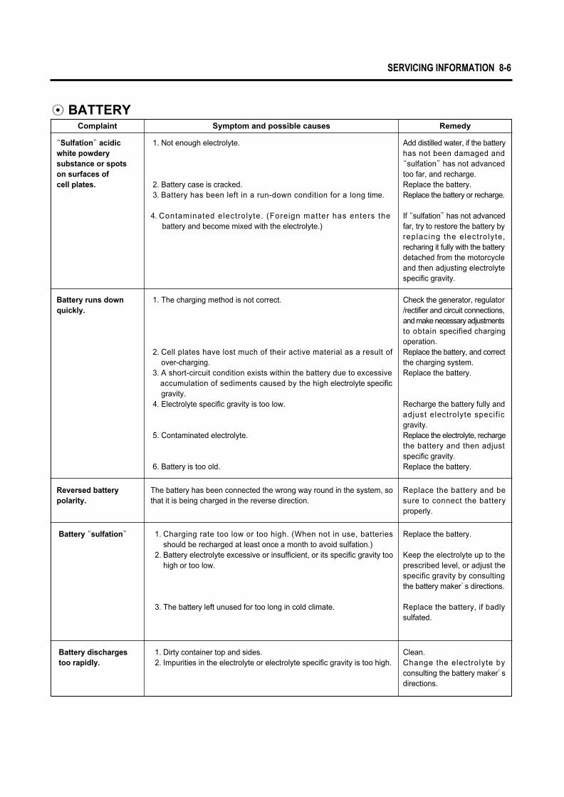
◉ BATTERYComplaint Symptom and possible causes Remedy
“Sulfation”acidicwhite powdery substance or spotson surfaces of cell plates.
1. Not enough electrolyte.
2. Battery case is cracked.3. Battery has been left in a run-down condition for a long time.
4. Contaminated electrolyte. (Foreign matter has enters thebattery and become mixed with the electrolyte.)
Add distilled water, if the battery has not been damaged and
“sulfation”has not advanced too far, and recharge.Replace the battery.Replace the battery or recharge.
If “sulfation”has not advanced far, try to restore the battery by replacing the electrolyte, recharing it fully with the battery detached from the motorcycle and then adjusting electrolyte specific gravity.
Battery runs downquickly.
1. The charging method is not correct.
2. Cell plates have lost much of their active material as a result ofover-charging.
3. A short-circuit condition exists within the battery due to excessive accumulation of sediments caused by the high electrolyte specific gravity.
4. Electrolyte specific gravity is too low.
5. Contaminated electrolyte.
6. Battery is too old.
Check the generator, regulator/rectifier and circuit connections, and make necessary adjustments to obtain specified chargingoperation.Replace the battery, and correct the charging system.Replace the battery.
Recharge the battery fully and adjust electrolyte specif icgravity.Replace the electrolyte, recharge the battery and then adjust specific gravity.Replace the battery.
Battery “sulfation” 1. Charging rate too low or too high. (When not in use, batteriesshould be recharged at least once a month to avoid sulfation.)
2. Battery electrolyte excessive or insufficient, or its specific gravity toohigh or too low.
3. The battery left unused for too long in cold climate.
Replace the battery.
Keep the electrolyte up to theprescribed level, or adjust thespecific gravity by consultingthe battery maker’s directions.
Replace the battery, if badlysulfated.
Battery discharges too rapidly.
1. Dirty container top and sides.2. Impurities in the electrolyte or electrolyte specific gravity is too high.
Clean.Change the electrolyte byconsulting the battery maker’sdirections.
Reversed battery polarity.
The battery has been connected the wrong way round in the system, so that it is being charged in the reverse direction.
Replace the battery and be sure to connect the batteryproperly.
SERVICING INFORMATION 8-6

8-7 SERVICING INFORMATION
◉ CHASSISComplaint Symptom and possible causes Remedy
Steering feels tooheavy or stiff.
1. Steering stem nut overtightened.2. Worn bearing or race in steering stem.3. Distorted steering stem.4. Not enough pressure in tires.
Adjust.Replace.Replace.Adjust.
Wobbling front wheel.
1. Distorted wheel rim.2. Worn-down wheel bearings.3. Defective or incorrect tire.4. Loosen nut on axle.5. Incorrect front fork oil level.6. Incorrect front wheel weight balance.
Replace.Replace.Replace.Retighten.Adjust.Adjust.
Steering oscillation.
1. Loss of balance between right and left front suspensions.2. Distorted front fork.3. Distorted front axle or crooked tire.4. Loose steering stem nut.5. Worn or incorrect tire or wrong tire pressure.6. Worn bearing/race in steering stem.
Replace.Repair or replace.Replace.Adjust.Adjust or replace.Replace.
Front suspension too soft.
1. Weakened springs.2. Not enough fork oil.3. Wrong viscous fork oil.4. Improperly set front fork damping force adjuster.
Replace.Refill.Replace.Adjust.
Front suspension too stiff.
1. Fork oil too viscous.2. Too much fork oil.3. Bent front axle.4. Improperly set front fork damping force adjuster.
Replace.Drain excess oil.Replace.Adjust.
Noisy frontsuspension.
1. Not enough fork oil.2. Loosen nuts on suspension.
Refill.Retighten.
Rear suspensiontoo soft.
1. Weakened springs.2. Rear suspension adjuster improperly set.
Replace.Adjust.
Rear suspensiontoo stiff.
1. Rear suspension adjuster improperly set.2. Worn swingarm bushing or bearing.
Adjust.Replace.
Noisy rearsuspension.
1. Loosen nuts on suspension.2. Worn swingarm bushing or bearing.
Retighten.Replace.
Wobbling rear wheel.
1. Distorted wheel rim.2. Worn-down rear wheel bearing.3. Defective or incorrect tire.4. Loose nut on axle.5. Worn swingarm bushing or bearing.6. Loosen nut on the rear shock.
Replace.Replace.Replace.Retighten.Replace.Retighten.

◉ BRAKESComplaint Symptom and possible causes Remedy
Poor braking(FRONT and REAR)
1. Not enough brake fluid in the reservoir.2. Air trapped in brake fluid circuit.3. Pads worn down.4. Too much play on brake lever or pedal.5. Oil adhesion on friction surface of pads.6. Worn disk.
Refill to level mark.Bleed air out.Replace.Adjust.Clean disk and pads.Replace.
Insufficient brakepower.
1. Leakage of brake fluid from hydraulic system.2. Worn pads.3. Oil adhesion of engaging surface of pads.4. Worn disk.5. Air in hydraulic system.
Repair or replace.Replace.Clean disk and pads.Replace.Bleed air.
Brake squeaking. 1. Carbon adhesion on pad surface.
2. Tilted pad.3. Damaged wheel bearing.4. Loosen front-wheel axle or rear-wheel axle.5. Worn pads.6. Foreign material in brake fluid.7. Clogged return port of master cylinder.
Repair surface withsandpaper.Modify pad fitting.Replace.Tighten to specified torque.Replace.Replace brake fluid.Disassemble and cleanmaster cylinder.
Leakage of brakefluid.
1. Insufficient tightening of connection joints.
2. Cracked hose.3. Worn piston and/or cup.
Tighten to specifiedtorque.Replace.Replace piston and/or cup.
Excessive brakelever stroke.
1. Air in hydraulic system.2. Insufficient brake fluid.
3. Improper quality of brake fluid.
Bleed air.Replenish fluid to specifiedlevel ; bleed air.Replace with correct fluid.
SERVICING INFORMATION 8-8

8-9 SERVICING INFORMATION
Special tools Part Number∙Part Name∙Description
09900-20101
Vernier Caliper
Used to conveniently measure various dimensions.
09900-20202
Micrometer (25~50mm)
Used for precise measurement (25~50mm measure ranges).
09900-20203
Micrometer (50~75mm)
Used for precise measurement (50~75mm measure ranges).
09900-20204
Micrometer (75~100mm)
Used for precise measurement (75~100mm measure ranges).
Special tools Part Number∙Part Name∙Description
09900-20201
Micrometer (0~25mm)
Used for precise measurement (00~25mm measure ranges).
09900-20508
Cylinder gauge set
Measure inside diameter of cylinder.
09900-20605
Dial calipers
Meassure width of conrod big-end.
09900-20606
Dial gauge
Meassure oscillation of wheel with using magnetic stand.
09900-20701
Magnetic stand
With using dial gauge.
09900-20806
Thickness gauge
Measure clearance of piston ring.
09900-21304
V-block
09900-21109
Torque wrench
With using magnetic stand.
Measure torque of tightening.
09900-22301
Plastigauge
Measure clearance of crankshaft thrust.
09900-22401
Small bore gauge
Measure inside diameter of conrod small-end.
09900-25002
Pocket tester
Measure voltage, electric current, resistance.
09900-26006
Engine tachometer
Measure rotational frequency of engine.
09910-20115
Conrod holder
Used to lock the crankshaft.
SPECIAL TOOLS
09900-25008
Multi circuit tester set
Inspect thermo-switch or temperature sensor.

Special tools Part Number∙Part Name∙Description
09910-32812
Crankshaft installer
09910-32813
Crankshaft installer adapter
09910-34510
Piston pin puller
Used to install the crankshaft in the crankcase.
Used to with the crankshaft installer.
Use to remove the piston pin.
09913-10760
Fuel level gauge
Measure height of carburetor.
09913-50121
Oil seal remover
09913-70122
Bearing installer
Used to remove the oil seal.
Used to drive bearing in.
Special tools Part Number∙Part Name∙Description
09913-75820
Bearing installer
Used to drive bearing in.
09913-76010
Bearing installer
Used to drive bearing in.
09913-80112
Bearing installer
Used to drive bearing in.
09915-64510
Compression gauge
Measure cylinder compression.
09915-74510
Oil pressure gauge
Measure oil pressure of 4-stroke engine.
Separate to crankcase.
Used to install or remove clutch sleeve hub nut.
09920-13120
Crankcase separater
09920-53710
Clutch sleeve hub holder
Used with valve spring compressor.
09916-14520
Valve spring compressor attachment
Used to remove and remounting valve stem.
09916-14510
Valve spring compressor
SERVICING INFORMATION 8-10
09921-20200
Bearing remover (10mm)
Used to remove bearing with the rotor remove sliding shaft.
09921-20210
Bearing remover (12mm)
Used to remove bearing with the rotor remove sliding shaft.
09923-73210
Bearing remover (17mm)
Used to remove bearing with the rotor remove sliding shaft.

8-11 SERVICING INFORMATION
Special tools Part Number∙Part Name∙Description Special tools Part Number∙Part Name∙Description
09923-74510
Bearing remover (20~35mm)
Used to remove bearing with the rotor remove sliding shaft.
Used to with bearing remover.
09930-30165
Rotor remover
09930-30102
Rotor remove sliding shaft
Used to remove rotor.
09940-34520
T-handle
Remove and remounting front fork oil cylinder.
09940-10122
Clamp wrench
A hook wrench to adjust the steering head of motorcycle.
09940-34561
Front fork assembling tool attachment “D”
Used with T-handle.
09940H30010
Engine mounting socket wrench (M20)
Used to install or remove engine mounting lock nut.
09940H35010
Engine mounting socket wrench (M26)
Used to install or remove swingarm mounting lock nut.
09941-34513
Steering race installer
Used to install steering outer race.
09941-50111
Wheel bearing remover
Used to remove wheel bearing.
09943-74111
Front fork oil level gauge
Used to drain the fork oil to the specified level.

ITEM
Coolant temperature sensor
Coolant drain bolt
Cooling fan mounting bolt
Cooling fan motor mounting bolt
Cooling fan thermo-switch
Radiator mounting bolt
Magneto rotor bolt
Magneto cover bolt
Muffler mounting bolt
Exhaust pipe bolt
Thermostat case bolt
Starter clutch bolt
Cylinder head cover bolt
Cylinder head base bolt
Cylinder base nut
Engine pulley nut
Engine oil drain plug
Engine mounting nut
Engine mounting bolt
Spark plug
Cam chain tensioner bolt
Cam chain tensioner adjuster bolt
Clutch sleeve hub nut
Primary drive gear nut
Camshaft housing bolt
Horn mounting bolt
1.8
1.1 ~ 1.4
0.8 ~ 1.2
0.8
1.3
0.8 ~ 1.2
11.0 ~ 17.0
1.0
1.8 ~ 2.8
1.8 ~ 2.8
1.0
2.3 ~ 2.8
0.8 ~ 1.2
4.0 ~ 4.5
1.2 ~ 1.6
0.8 ~ 1.2
0.7 ~ 1.1
13.0 ~ 16.0
2.1
4.5 ~ 7.0
3.5 ~ 5.0
1.5 ~ 3.0
1.1
0.8 ~ 1.2
0.8 ~ 1.2
1.1
2.6
4.0 ~ 6.0
4.0 ~ 6.0
1.2
0.8 ~ 1.2
kg∙m
18
11 ~ 14
8 ~ 12
8
13
8 ~ 12
110 ~ 170
10
18 ~ 28
18 ~ 28
10
23 ~ 28
8 ~ 12
40 ~ 45
12 ~ 16
8 ~ 12
7 ~ 11
130 ~ 160
21
45 ~ 70
35 ~ 50
15 ~ 30
11
8 ~ 12
8 ~ 12
11
26
40 ~ 60
40 ~ 60
12
8 ~ 12
N∙m
◉ ENGINE
TIGHTENING TORQUE
SERVICING INFORMATION 8-12
Cylinder head bolt
Engine mounting lock nut
Crankcase bolt
M 6
M 10
M 20
M 6
M 8

8-13 SERVICING INFORMATION
ITEM
Rear shock absorber mounting nut (Upper)
Rear shock absorber mounting bolt (Lower)
Rear pulley bolt
Rear axle bolt
Swingarm pivot nut
Swingarm pivot shaft
Swingarm mounting lock nut
Steering stem nut
Steering stem head nut
Front and Rear brake disk bolt
Front brake master cylinder mounting bolt
Rear brake master cylinder mounting bolt
Front and Rear brake caliper air bleeder valve
Front and Rear brake caliper mounting bolt
Front and Rear brake hose union bolt
Front axle bolt
Front axle pinch bolt
Front fork damper rod bolt
Front fork upper clamp bolt
Front fork cap bolt
Front fork lower clamp bolt
Front fork inner rod lock nut
Footrest mounting bolt
Frame down tube mounting bolt
Handlebar mounting bolt
2.0 ~ 3.0
3.5 ~ 5.5
2.0 ~ 3.0
9.0 ~ 14.0
5.0 ~ 7.0
1.5 ~ 3.0
7.0 ~ 8.0
8.0 ~ 10.0
8.0 ~ 10.0
1.8 ~ 2.8
0.5 ~ 0.8
1.8 ~ 2.8
0.6 ~ 0.8
1.8 ~ 2.8
2.0 ~ 2.5
5.0 ~ 8.0
1.5 ~ 2.5
3.0 ~ 4.0
2.2 ~ 3.5
3.0 ~ 4.0
2.2 ~ 3.5
1.75 ~ 2.25
4.0 ~ 6.0
2.2 ~ 3.5
4.0 ~ 5.0
20 ~ 30
35 ~ 55
20 ~ 30
90 ~ 140
50 ~ 70
15 ~ 30
70 ~ 80
80 ~ 100
80 ~ 100
18 ~ 28
5 ~ 8
18 ~ 28
6 ~ 8
18 ~ 28
20 ~ 25
50 ~ 80
15 ~ 25
30 ~ 40
22 ~ 35
30 ~ 40
22 ~ 35
17.5 ~ 22.5
40 ~ 60
22 ~ 35
40 ~ 50
kg∙mN∙m
◉ CHASSIS
M26

SERVICE DATA
ITEM STANDARD LIMIT
31.0 (1.22)
25.5 (1.00)
0.1 ~ 0.2 (0.004 ~ 0.008)
0.28 ~ 0.32 (0.011 ~ 0.013)
0.020 ~ 0.047 (0.0008 ~ 0.0019)
0.030 ~ 0.057 (0.0012 ~ 0.0022)
———
4.500 ~ 4.512 (0.1771 ~ 0.1776)
4.465 ~ 4.480 (0.1758 ~ 0.1764)
4.455 ~ 4.470 (0.1754 ~ 0.1760)
———
———
45�
———
———
———
4.2 ~ 4.8kgf (9.3 ~ 10.6 lbs)
at length 29.9mm (1.18 in)
17.0 ~ 19.6kgf (37.5 ~ 43.2 lbs)
at length 33.4mm (1.32 in)
1.2 ~ 1.7 (0.047 ~ 0.067)
IN.
EX.
IN.
EX.
IN.
EX.
IN. & EX.
IN. & EX.
IN.
EX.
IN. & EX.
IN. & EX.
IN. & EX.
IN. & EX.
Inner
Outer
Inner.
Outer
———
———
———
———
———
———
0.35 (0.014)
———
———
———
0.05 (0.002)
0.50 (0.02)
———
0.03 (0.0012)
36.8 (1.45)
39.8 (1.57)
———
———
◉ VALVE + GUIDE
Valve diam.
Valve clearance (When cold)
Valve guide to valve stem clearance
Valve stem deflection
Valve guide I.D.
Valve stem O.D.
Valve stem runout
Valve head thickness
Valve seat width
Valve seat angle
Valve head radial runout
Valve spring free length
Valve spring tension
SERVICING INFORMATION 8-14
Unit : mm (in)

ITEM STANDARD LIMIT
14kg/cm2 (at 500 rpm)
0.045 ~ 0.075 (0.0018 ~ 0.0030)
81.500 ~ 81.515 (3.2087 ~ 3.2093)
81.440 ~ 81.455 (3.2063 ~ 3.2069)(Measure at 20mm (0.79 in) from the skirt end)
20.002 ~ 20.008 (0.7875 ~ 0.7877)
19.996 ~ 20.000 (0.7872 ~ 0.7874)
12 kg/cm2
0.120 (0.0047)
81.575 (3.2116)
81.380 (3.2039)
0.05 (0.002)
7.9 (0.311)
8.4 (0.330)
0.5 (0.020)
0.7 (0.028)
0.180 (0.007)
0.150 (0.006)
———
———
———
———
———
20.030 (0.7886)
19.980 (0.7866)
Approx 9.9 (0.390)
Approx 10.5 (0.413)
0.20 ~ 0.35 (0.008 ~ 0.013)
0.20 ~ 0.35 (0.008 ~ 0.013)
———
———
1.21 ~ 1.23 (0.0476 ~ 0.0484)
1.01 ~ 1.03 (0.040 ~ 0.041)
2.01 ~ 2.03 (0.079 ~ 0.080)
0.970 ~ 0.990 (0.0382 ~ 0.0390)
1.170 ~ 1.190 (0.0461 ~ 0.0469)
1st
2nd
1st
2nd
1st
2nd
1st
2nd
Oil
1st
2nd
———
◉ CYLINDER + PISTON + PISTON RING
Compression pressure
Piston to cylinder clearance
Cylinder bore
Piston diam.
Cylinder or cylinder head distortion
Piston ring free end gap
Piston ring end gap (Assembly condition)
Piston ring to groove clearance
Piston ring groove width
Piston ring thickness
Piston pin hole bore
Piston pin O.D.
8-15 SERVICING INFORMATION
Unit : mm (in)

ITEM STANDARD LIMIT
Conrod small end I.D.
Conrod deflection
Conrod big end side clearance
Conrod big end width
Crank web to web width
Crankshaft runout
20.006 ~ 20.014 (0.7876 ~ 0.7880)
———
0.17 ~ 0.32 (0.007 ~ 0.013)
20.95 ~ 21.00 (0.825 ~ 0.827)
96.9 ~ 97.1 (3.815 ~ 3.823)
———
20.040 (0.7890)
3.0 (0.12)
0.50 (0.020)
———
———
0.05 (0.002)
◉ CONROD + CRANKSHAFT
SERVICING INFORMATION 8-16
Oil pressure
Oil pump reduction ratio
2.0 ~ 6.0 kg/cm2
(at 60 ℃, 3,000 rpm)
1.3 (45/34)
———
———
ITEM STANDARD NOTE
◉ OIL PUMP
ITEM STANDARD LIMIT
Clutch cable play
Drive plate thickness
Drive plate claw width
Driven plate distortion
Clutch spring free length
———
2.62 (0.103)
3.12 (0.123)
15.1 (0.595)
15.1 (0.595)
0.1 (0.004)
51 (2.008)
◉ CLUTCH
2 (0.08)
2.92 ~ 3.08 (0.115 ~ 0.121)
3.42 ~ 3.58 (0.135 ~ 0.141)
15.9 ~ 16.0 (0.626 ~0.630)
15.9 ~ 16.0 (0.626 ~0.630)
———
54.2 (2.134)
ITEM STANDARD LIMIT
Camshaft journal holder I.D.
Camshaft journal oil clearance
Cylinder and cylinder head distortion
Cylinder head cover distortion
Cam chain pin (Arrow “3”)
———
———
16th pin
35.28 ~ 35.32 (1.389 ~ 1.391)
33.38 ~ 33.42 (1.314 ~ 1.316)
21.959 ~ 21.980 (0.8645 ~ 0.8654)
———
IN.
EX.
IN. & EX.
IN. & EX.
34.98 (1.377)
33.08 (1.302)
———
0.15 (0.006)
0.05 (0.002)
0.05 (0.002)
———
◉ CAMSHAFT + CYLINDER HEAD Unit : mm (in)
Unit : mm (in)
Unit : mm (in)
NO. 1
NO. 2
NO. 1
NO. 2
Cam height
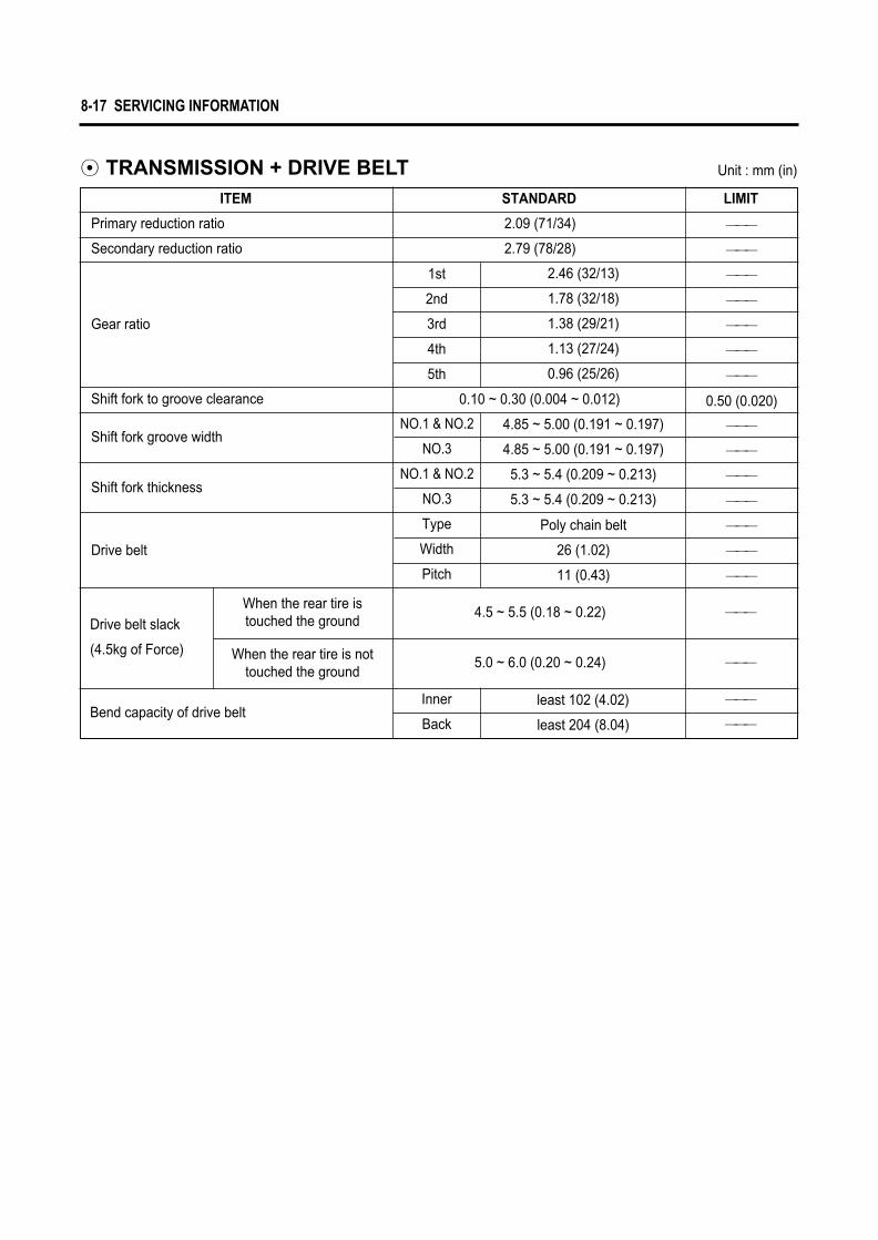
Primary reduction ratio
Secondary reduction ratio
Shift fork to groove clearance
2.09 (71/34)
2.79 (78/28)
4.85 ~ 5.00 (0.191 ~ 0.197)
4.85 ~ 5.00 (0.191 ~ 0.197)
5.3 ~ 5.4 (0.209 ~ 0.213)
5.3 ~ 5.4 (0.209 ~ 0.213)
least 102 (4.02)
———
———
———
———
———
———
———
0.50 (0.020)
———
———
———
———
———
———
———
ITEM STANDARD LIMIT
◉ TRANSMISSION + DRIVE BELT
2.46 (32/13)
1.78 (32/18)
1.38 (29/21)
1.13 (27/24)
0.96 (25/26)
Poly chain belt
26 (1.02)
11 (0.43)
1st
2nd
3rd
4th
5th
Type
Width
Pitch
NO.1 & NO.2
NO.3
NO.1 & NO.2
NO.3
0.10 ~ 0.30 (0.004 ~ 0.012)
8-17 SERVICING INFORMATION
Gear ratio
Shift fork groove width
Shift fork thickness
Drive belt
4.5 ~ 5.5 (0.18 ~ 0.22)
5.0 ~ 6.0 (0.20 ~ 0.24)
least 204 (8.04)
Inner
Back
Drive belt slack
(4.5kg of Force)
When the rear tire istouched the ground
When the rear tire is nottouched the ground
Bend capacity of drive belt
Unit : mm (in)
———
———
———
———

SERVICING INFORMATION 8-18
Carburetor type
Bore size
Idle r.p.m.
Float height
Throttle cable play
Main jet (M.J.)
Main air jet (M.A.J.)
Jet needle (J.N.)
Needle jet (N.J.)
Pilot jet (P.J.)
Throttle valve (TH.V.)
By-pass (B.P.)
Valve seat (V.S.)
Starter jet (G.S.)
Pilot screw (P.S.)
Pilot outlet (P.O.)
PV. Stroke (P.V.)
BDSR39 TYPE(DOUBLE)
ф 39
1,300~1,500 rpm
7 (0.28)
0.5~1.0 (0.02 ~ 0.04)
FRONT
125
45
6DH64-53-3
P-OM
20
95
1.5
50
STD
1.0
30.7
REAR
122.5
45
6DH65-53-3
P-OM
20
95
1.5
50
STD
1.0
30.7
ITEM SPECIFICATION
◉ CARBURETOR
#10.8
#20.8
#30.8
#10.8
#20.8
#30.8
Unit : mm (in)

8-19 SERVICING INFORMATION
Thermostat valve operating temperature
Thermostat valve lift
Engine coolant temperature sensor resistance
Cooling fan thermo-switch operating temperature
Engine coolant type
Engine coolant capacity
Over 8mm /100℃
ITEM STANDARD LIMIT
◉ THERMOSTAT + COOLING FAN + COOLANT
Valve opening
Valve full open
Valve closing
60℃
85℃
110℃
125℃
OFF→ON
ON→OFF
Reserve tank side
Radiator side
Engine side
88℃
100℃
83℃
Approx. 125Ϊ
Approx. 48.5Ϊ
Approx. 24Ϊ
Approx. 15Ϊ
Approx. 95℃
Over 88℃
230㎖
430㎖
940㎖
Use an antifreeze/coolant compatible with
aluminum radiator, mixed with distilled
water only, at the ratio of 50 : 50

Battery
Type
Capacity
Standard elec-
trolyte S.G.
◉ ELECTRICAL
License plate lamp
Brake / Tail lamp
Turn signal lamp
Neutral indicator lamp
Turn signal indicator lamp (Right & left)
High beam indicator lamp
5W
LED type
10W×4
VFD type
VFD type
VFD type
60W
55W
ITEM SPECIFICATION
HI
LO
◉ WATTAGE
CAUTIONDo not use except the specified bulb (Wattage).
SERVICING INFORMATION 8-20
Ignition timing
Spark plug
Spark performance
Fuse size
Ignition coil resistance
Magneto coil resistance
Magneto no-load voltage
Battery standard charging voltage
CR8E
0.7~0.8 (0.028 ~ 0.032)
CR7E
CR8E
CR9E
Over 8mm (0.32)
3.5 ~ 5.5 Ϊ
20 ~ 31 ㏀
80 ~ 120 Ϊ
0.4 ~ 0.9 Ϊ
STX14-BS
12V 12Ah
30A
15A
Primary
Secondary
Main
Head lamp
Pick-up coil
Charging coil
G-L
Y-Y
Type
Gap
Hot type
Standard type
Cold type
ITEM STANDARD
BTDC 5�/1,500rpm
Over 70V / 5,000 rpm
13.5 ~ 15.0V / 5,000 rpm
NOTE
1.320 at 20℃ (68℉)
Head lamp
※ LED : Light Emitting Diode
VFD : Vacuum Fluorescent Display
Unit : mm (in)
Unit : W

8-21 SERVICING INFORMATION
Front fork stroke
Front fork spring free length
Front fork oil type
Front fork oil level
Front fork oil capacity (each leg)
Rear wheel travel
Swingarm pivot shaft runout
Rear shock absorber pre-load position
Rear shock absorber spring length
———
———
———
———
———
———
0.6 (0.024)
———
———
130 (5.12)
470 (18.5)
TELLUS #32
215mm (8.5 in) from end of outer tube(when maximum compressed without spring)
420cc
90 (3.54)
———
1 / 5 position
223 (8.78)
ITEM STANDARD LIMIT
◉ SUSPENSION
STANDARD FRONT FORK DAMPING FORCE
Rebound Compression
Solo riding
Dual riding
Softer
Standard
Stiffer
Turn to “S”direction
3 clicks out from end of “H”direction
Turn to “H”direction
3 clicks out from end of “H”direction
Turn to “S”direction
End of “S”direction
Turn to “H”direction
2 clicks out from end of “S”direction
Unit : mm (in)

Rear brake pedal height
Brake disk thickness
Brake disk runout
Master cylinder bore
Master cylinder piston diam.
Brake caliper cylinder bore
Brake caliper piston diam.
Brake fluid type
Wheel runout
Wheel axle runout
Tire size
Wheel rim size
4.0 (0.16)
4.3 (0.17)
———
15.870 ~ 15.913 (0.6248 ~ 0.6265)
12.700 ~ 12.743 (0.5000 ~ 0.5017)
15.827 ~ 15.854 (0.6227 ~ 0.6242)
12.657 ~ 12.684 (0.4983 ~ 0.4994)
25.4 (1.00)
25.4 (1.00)
DOT3 or DOT4
DOT4
———
———
———
———
120/70 - ZR 18 59W
180/55 - ZR 17 73W
J18×MT3.50
J17×MT5.50
408 (16.1) [when one person riding from the ground] ———
3.0 (0.12)
3.0 (0.12)
0.3 (0.012)
———
———
———
———
———
———
———
———
2.0 (0.08)
2.0 (0.08)
0.25 (0.01)
0.25 (0.01)
———
———
———
———
Front
Rear
Front∙Rear
Front
Rear
Front
Rear
Front∙Rear
Front∙Rear
Front
Rear
Axial
Radial
Front
Rear
Front
Rear
Front
Rear
ITEM STANDARD LIMIT
◉ BRAKE + WHEEL
SERVICING INFORMATION 8-22
Unit : mm (in)

8-23 SERVICING INFORMATION
NOTE
Fuel type
Fuel tank capacity
Engine oil type
Engine oil capacity
16 ℓ
Gasoline used should be graded 91 octane or higher.An unleaded gasoline is recommened.
API Over SL (SAE 10W/40)
3,000 ㎖
3,200 ㎖
3,400 ㎖
ITEM SPECIFICATION
◉ FUEL + OIL
Change
Filter change
Overhaul
◉ TIRE PRESSURE
COLD INFLATIONTIRE PRESSURE
NORMAL RIDING
FRONT
SOLO RIDING
kPa kg/㎠ psi kPa kg/㎠ psi
221
245
2.25
2.50
33.0
36.0
221
285
2.25
2.90
33.0
42.0
DUAL RIDING
REAR

SERVICING INFORMATION 8-24
WIRE AND CABLE ROUTING
IGN
ITIO
N S
/W
WEL
D C
LAM
P
STAR
TER R
ELAY
PAR
T
WEL
D C
LAM
PL/
WIR
E BAT
TERY
PLU
SEN
GIN
E EA
RTH
(L/
WIR
E BAT
TERY
MIN
US)
3661
8-30
610
TAIL
& S
TOP
LAM
PLI
CEN
SE L
AMP
RR T
URN
LAM
P R/L
WEL
D C
LAM
P
WEL
DIN
G C
LAM
P
WEL
DIN
G C
LAM
P
WEL
D C
LAM
P(#
1)
TAPP
ING
OF
INST
ALLA
TIO
N B
ASIS
RR IG
NIT
ION
CO
IL
CO
UP.
FU
EL G
AUG
E
CO
UP.
WAT
ER T
EMP
GAU
GE
WEL
D C
LAM
P(#
1)
WEL
D C
LAM
PREG
ULA
TOR
HAN
DLE
S/W
Lh
SPEE
DO
MET
ER
WIR
ING
HAR
NES
S
※ In
stal
l to
the
orde
r REL
AY (3E
A)
BATTERY

8-25 SERVICING INFORMATION
SPEE
DO
MET
ER
WEL
D C
LAM
PH
ARN
ESS,
WIR
ING
HO
RN
NO
ISE
FILT
ER
0940
7-14
403
WIR
ING
HAR
NES
SM
AGN
ETO
GEA
R P
OSI
TIO
N S
/W
WEL
D C
LAM
P (#
1)H
ARN
ESS
TURN
SIG
NAL
RELA
Y
0940
7-20
406
HAN
DLE
S/W
Lh
CLU
TCH
LEV
ER S
/W
COUP
. HAN
DLE S
/W Lh
COUP
. SPE
EDOM
ETER
COUP
. FUE
L GAU
GE
TAPP
ING
OF
INST
ALLA
TIO
N B
ASIS
REL
AY (3E
A)
LIC
ENSE
LAM
P
REF
LEX
REF
LEC
TOR R
R
REF
LEX
REF
LEC
TOR S
IDE
RR (2E
A)(E
xcep
tion
of th
e ap
plic
atio
n ve
hicl
e of
Eur
opea
n la
w)
WEL
D C
LAM
PW
ELD
CLA
MP
L/W
IRE
RR C
OM
BI
0940
7-20
406
MAG
NET
OG
EAR P
OSI
TIO
N S
/W
NEU
TRAL
S/W
SID
E ST
AND
S/W
THER
MO
SW
ITC
H
CO
UP.
S/S
TAN
D
WEL
D C
LAM
P
WEL
D C
LAM
PH
ARN
ESS
RAD
IATO
R F
AN
L/W
IRE,
SPE
ED S
ENSO
R
0940
4-08
40309
407-
2040
6
CO
UP.
RAD
IATO
R F
AN
REG
ULA
TOR
DIO
DE
(2EA
)D
IOD
E, H
AZAR
DD
IOD
E, S
/STA
ND
(VIN
YL T
UBE)
WEL
D C
LAM
P(#
1)W
IRIN
G H
ARN
ESS

SERVICING INFORMATION 8-26
BAT
TERY
MIN
US
BAT
TERY
PLU
SW
ELD
CLA
MP
L/W
IRE
WAT
ER T
EMP
GAU
GE
STAR
TER R
ELAY
IGN
ITO
R
CO
UP.
IGN
ITIO
N S
/W
0940
7-20
406
HAN
DLE
S/W
Rh
CO
UP.
HAN
DLE
S/W
Rh
Inst
all i
nsid
e of
HEA
D L
AMP
HO
USI
NG
LOC
K S
TEER
ING
IGN
ITIO
N S
/W
WEL
D C
LAM
PRR B
RAK
E S/
W
RR B
RAK
E S/
W
0940
7-20
406
L/W
IRE,
STA
RTE
R M
OTO
RH
OSE
, TH
EMO
STAT
BYP
ASS
L/W
IRE
STAR
TER M
OTO
R
WEL
D C
LAM
PH
ARN
ESS
STAR
TER R
ELAY
IGN
ITIO
N S
/WRR B
RAK
E S/
W
A

8-27 SERVICING INFORMATION
09407-20406HANDLE S/W
09407-20406HANDLE S/WCLUTCH LEVER S/W
09407-20406
WIRING HARNESS
FT TURN L
HEAD LAMP COUP.
09407-20406
FT TURN R
09404-06405L/WIRE, FT TURN R/LL/WIRE, C/LEVER S/W
COUP. HANDLE S/W Lh
09407-20406
B

SERVICING INFORMATION 8-28
VIEW A(ENGINE EARTH INSTALLATION DIRECTION)
CRANK CASE R
PIPE FRAME Lh
SIDE L
TOP
WIRING HARNESS
L/WIRE BATTERY MINUS
FRONT
"#1" MARK WELDING CLAMP PARTS (3EA)
VIEW B

8-29 SERVICING INFORMATION
FRONT CYLINDER REAR CYLINDER
CAUTION FOR HIGHTENTION CORD INSTALLATION DIRECTION
WELDING CLAMP OPERATION METHOD
FRAME
WELD CLAMPWIRING HARNESS

SERVICING INFORMATION 8-30
WIRING DIAGRAM
E/G
STO
PHAN
DLE
SW
ITC
H R
h
HAZ
ARD
STAR
TFR
ON
T BRAK
E
STAR
TER R
ELAY
IGN
ITO
RTU
RN
REL
AY
WAT
ER T
EMP
GAU
GE
FAN
MO
TOR
THER
MO
S/W
FAN
MOT
ORRE
LAY
RR T
URN
R
TAIL
& S
TOP
LIC
ENSE
PLA
TE
RR T
URN
L
(15A
)(3
0A)
FUSE
BO
XEA
RTH
BAT
TERY(
MF)
12V(
12Ah
)
REC
& R
EG
MAG
NET
O
SID
E ST
AND
S/W
FUEL
GAU
GE
UN
IT
HO
RN
PASS
HAN
DLE
SW
ITC
H L
h
HO
RN
SPEE
DO
MET
ER
FRO
NT
SPEE
DSE
NSOR
DIM
MER
TURN
SIG
NAL
RR IG
.C
OIL
NEU
TRAL
S/W
FUSE
BO
X
SIDE
STA
NDRE
LAY
HEAD
LAM
PRE
LAY
DIOD
E #
2DI
ODE
#1
FT IG
.C
OIL
STAR
TER M
OTO
R
STO
P LA
MP
S/W
DIO
DE
#3
IGN
ITIO
N S
/W
CLU
TCH
LEV
ER S
/W
FT T
URN
R
HEA
D L
AMP
POSI
TIO
N L
AMP
FT T
URN
L
FREE
ON
STO
P
RU
N
OFF ON
OFF ON
OFF ON
OFF
ON
ON
FREE
FREE
PUSH
OFF
ENG
.
ON
N
FREE
PUSH
FREE
PUSH
LOHI
L
PUSH R
WIR
E C
OLO
RB
:
Bla
ckLg
:
Ligh
t gre
enY
: Yel
low
RB
: Red
with
Bla
ck tr
acer
Br
: Br
own
O
: O
rang
eBG
: Bla
ck w
ith G
reen
trac
erR
W: R
ed w
ith W
hite
trac
erG
:
Gre
en
R
: R
edBW
: Bla
ck w
ith W
hite
trac
erW
B: W
hite
with
Bla
ck tr
acer
Gr
: G
ray
Sb
: Li
ght b
lue
BR
: Bla
ck w
ith R
ed tr
acer
WR
: W
hite
with
Red
trac
erL
:
Blue
W
: W
hite
LW
: Blu
e w
ith W
hite
trac
er
YB
: Yel
low
with
Bla
ck tr
acer

SH
IM N
o.
HO
W T
O U
SE
TH
E C
HA
RT
1. M
easu
re th
e ta
ppet
cle
aran
ce.(W
hen
cold
)2.
Mea
sure
the
shim
thic
knes
s at
pre
sent
.3.
Loo
k fo
r mee
ting
spac
e in
that
hor
izon
tal l
ine
for t
hick
ness
and
ver
tical
line
for c
lear
ance
.
(EX
AM
PLE
)W
hen
the
tapp
et c
lear
ance
is 0
.23m
m a
nd th
e sh
im th
ickn
ess
at p
rese
nt is
1.7
0mm
, the
shi
m
thic
knes
s sh
ould
be
used
1.8
0mm
.
TAP
PE
T S
HIM
SE
LEC
TIO
N C
HA
RT
(IN.)
Spe
cifie
d cl
eara
nce
- Adj
ustm
ent u
nnec
essa
ry
1.20
1.20
0.00
~ 0
.04
0.05
~ 0
.09
0.10
~ 0
.20
0.21
~ 0
.25
0.26
~ 0
.30
0.31
~ 0
.35
0.36
~ 0
.40
0.41
~ 0
.45
0.46
~ 0
.50
0.51
~ 0
.55
0.56
~ 0
.60
0.61
~ 0
.65
0.66
~ 0
.70
0.71
~ 0
.75
0.76
~ 0
.80
0.81
~ 0
.85
0.86
~ 0
.90
0.91
~ 0
.95
0.96
~ 1
.00
1.01
~ 1
.05
1.06
~ 1
.10
1.11
~ 1
.15
1.25
1.30
1.35
1.40
1.45
1.50
1.55
1.60
1.65
1.70
1.75
1.80
1.85
1.90
1.95
2.00
2.05
2.10
1.20
1.25
1.30
1.35
1.40
1.45
1.50
1.55
1.60
1.65
1.70
1.75
1.80
1.85
1.90
1.95
2.00
2.05
2.10
2.15
1.30
1.35
1.40
1.45
1.50
1.55
1.60
1.65
1.70
1.75
1.80
1.85
1.90
1.95
2.00
2.05
2.10
2.15
2.20
2.20
1.35
1.40
1.45
1.50
1.55
1.60
1.65
1.70
1.75
1.80
1.85
1.90
1.95
2.00
2.05
2.10
2.15
2.20
1.40
1.45
1.50
1.55
1.60
1.65
1.70
1.75
1.80
1.85
1.90
1.95
2.00
2.05
2.10
2.15
2.20
1.45
1.50
1.55
1.60
1.65
1.70
1.75
1.80
1.85
1.90
1.95
2.00
2.05
2.10
2.15
2.20
1.50
1.55
1.60
1.65
1.70
1.75
1.80
1.85
1.90
1.95
2.00
2.05
2.10
2.15
2.20
1.55
1.60
1.65
1.70
1.75
1.80
1.85
1.90
1.95
2.00
2.05
2.10
2.15
2.20
1.60
1.65
1.70
1.75
1.80
1.85
1.90
1.95
2.00
2.05
2.10
2.15
2.20
1.65
1.70
1.75
1.80
1.85
1.90
1.95
2.00
2.05
2.10
2.15
2.20
1.70
1.75
1.80
1.85
1.90
1.95
2.00
2.05
2.10
2.15
2.20
1.75
1.80
1.85
1.90
1.95
2.00
2.05
2.10
2.15
2.20
1.80
1.85
1.90
1.95
2.00
2.05
2.10
2.15
2.20
1.85
1.90
1.95
2.00
2.05
2.10
2.15
2.20
1.90
1.95
2.00
2.05
2.10
2.15
2.20
1.95
2.00
2.05
2.10
2.15
2.20
2.00
2.05
2.10
2.15
2.20
2.05
2.10
2.15
2.20
2.10
2.15
2.20
2.15
2.20
2.20
SHIM
THICK
NESS
AT PR
ESEN
T(m
m)
MEA
SUR
ING
TA
PPET
C
LEAR
ANC
E (m
m)
120
1.25
125
1.30
130
1.35
135
1.40
140
1.45
145
1.50
150
1.55
155
1.60
160
1.65
165
1.70
170
1.75
175
1.80
180
1.85
185
1.90
190
1.95
195
2.00
200
2.05
205
2.10
210
2.15
215
2.20
220
HYOS
UNG
MOTO
RS &
MAC
HINE
RY IN
C.

HYOS
UNG
MOTO
RS &
MAC
HINE
RY IN
C.
SH
IM N
o.
TAP
PE
T S
HIM
SE
LEC
TIO
N C
HA
RT
(EX
.)
Spe
cifie
d cl
eara
nce
- Adj
ustm
ent u
nnec
essa
ry
1.20
1.20
0.13
~ 0
.17
0.18
~ 0
.22
0.23
~ 0
.27
0.28
~ 0
.32
0.33
~ 0
.37
0.38
~ 0
.42
0.43
~ 0
.47
0.48
~ 0
.52
0.53
~ 0
.57
0.58
~ 0
.62
0.63
~ 0
.67
0.68
~ 0
.72
0.73
~ 0
.77
0.78
~ 0
.82
0.83
~ 0
.87
0.88
~ 0
.92
0.93
~ 0
.97
0.98
~ 1
.02
1.03
~ 1
.07
1.08
~ 1
.12
1.13
~ 1
.17
1.18
~ 1
.22
1.23
~ 1
.27
1.25
1.30
1.35
1.40
1.45
1.50
1.55
1.60
1.65
1.70
1.75
1.80
1.85
1.90
1.95
2.00
2.05
1.20
1.25
1.30
1.35
1.40
1.45
1.50
1.55
1.60
1.65
1.70
1.75
1.80
1.85
1.90
1.95
2.00
2.05
2.10
1.20
1.25
1.30
1.35
1.40
1.45
1.50
1.55
1.60
1.65
1.70
1.75
1.80
1.85
1.90
1.95
2.00
2.05
2.10
2.15
1.30
1.25
1.35
1.40
1.45
1.50
1.55
2.15
2.10
2.05
2.00
1.95
1.90
1.85
1.80
1.75
1.70
1.65
1.60
1.55
1.50
1.45
1.40
1.35
1.30
2.20
1.35
1.40
1.45
1.50
1.55
1.60
1.40
1.45
1.50
1.55
1.60
1.65
1.45
1.50
1.55
1.60
1.65
1.70
1.50
1.55
1.60
1.65
1.70
1.75
1.55
1.60
1.65
1.70
1.75
1.80
1.60
1.65
1.70
1.75
1.80
1.85
1.65
1.70
1.75
1.80
1.85
1.90
1.70
1.75
1.80
1.85
1.90
1.95
1.75
1.80
1.85
1.90
1.95
2.00
1.80
1.85
1.90
1.95
2.00
2.05
1.85
1.90
1.95
2.00
2.05
2.10
1.60
1.65
1.70
1.75
1.80
1.85
1.90
1.95
2.00
2.05
2.10
2.15
1.65
1.70
1.75
1.80
1.85
1.90
1.95
2.00
2.05
2.10
2.15
1.70
1.75
1.80
1.85
1.90
1.95
2.00
2.05
2.10
2.15
1.75
1.80
1.85
1.90
1.95
2.00
2.05
2.10
2.15
1.80
1.85
1.90
1.95
2.00
2.05
2.10
2.15
1.85
1.90
1.95
2.00
2.05
2.10
2.15
1.90
1.95
2.00
2.05
2.10
2.15
1.95
2.00
2.05
2.10
2.15
2.00
2.05
2.10
2.15
2.05
2.10
2.15
2.10
2.15
2.15
1.90
1.95
2.00
2.05
2.10
2.15
1.95
2.00
2.05
2.10
2.15
2.00
2.05
2.10
2.15
2.05
2.10
2.15
2.10
2.15
2.15
SHIM
THICK
NESS
AT PR
ESEN
T(m
m)
MEA
SUR
ING
TA
PPET
C
LEAR
ANC
E (m
m)
120
1.25
125
1.30
130
1.35
135
1.40
140
1.45
145
1.50
150
1.55
155
1.60
160
1.65
165
1.70
170
1.75
175
1.80
180
1.85
185
1.90
190
1.95
195
2.00
200
2.05
205
2.10
210
2.15
215
2.20
220
HO
W T
O U
SE
TH
E C
HA
RT
1. M
easu
re th
e ta
ppet
cle
aran
ce.(W
hen
cold
)2.
Mea
sure
the
shim
thic
knes
s at
pre
sent
.3.
Loo
k fo
r mee
ting
spac
e in
that
hor
izon
tal l
ine
for t
hick
ness
and
ver
tical
line
for c
lear
ance
.
(EX
AM
PLE
)W
hen
the
tapp
et c
lear
ance
is 0
.35m
m a
nd th
e sh
im th
ickn
ess
at p
rese
nt is
1.7
0mm
, the
shi
m
thic
knes
s sh
ould
be
used
1.7
5mm
.

Prepared by
HYOSUNG MOTORS & MACHINERY INC.
1st Ed. JUL. 2005.
Manual No. 99000-51210
Printed in Korea


