

FRENI E FRIZIONIELETTROMAGNETICI A POLVEREELECTROMAGNETIC POWDER BRAKES AND CLUTCHES
E L E F L E X
FRENI E FRIZIONIELETTROMAGNETICI A POLVEREELECTROMAGNETIC POWDER BRAKES AND CLUTCHES
E L E F L E X

La serie ELEFLEX di freni e frizioni a polvere elettromagnetica è uno dei nostri più collaudati prodotti che produciamo e commercializziamo da oltre 20 anni.Questa lunga esperienza, con migliaia di applicazioni in svariati settori, la costante ricerca nei materiali e lo studio del comportamento di questi freni, ci hanno permesso di accrescere il nostro know-how e di apportare continue migliorie al nostro prodotto.I nostri freni e frizioni ELEFLEX sono stati recentemente rinnovati allo scopo di offrire un prodotto innovativo che assicuri una bassissima coppia residua.Questa gamma di freni garantisce:- alta precisione nel controllo della coppia,- compattezza,- nessuna emissione di materiale inquinante,- coppia residua ridotta.Sono quindi particolarmente indicati nel settore della stampa, su macchine fl essografi che e rotocalco, ma anche in ambienti alimentari o particolarmente esigenti in quanto a pulizia ed emissione di polveri. Ideali nel settore food-packaging, su macchine laminatrici o per il fi lm plastico, ed in tutte quelle applicazioni con tiri molto bassi grazie alle bassissime coppie residue.Una rete capillare di distributori in tutto il mondo vi garantisce un servizio post-vendita ed un’assistenza tecnica altamente specializzata entro poche ore dalla chiamata.
ELEFLEX: caratteristiche / characteristics
m a d e i n I t a l y
The ELEFLEX range of electromagnetic powder brakes and clutches is one our most tried and tested products, and has been in production for over 20 years.This wealth of experience, covering thousands of applications in a various sectors, the constant research into materials and the studies carried out into how these brakes perform have permitted us to acquire extensive know-how, and continually improve our product.Our ELEFLEX brakes and clutches have been upgraded recently in order to offer an innovative product that guarantees extremely low residual torque.This range of brakes features:- High precision torque control- Small size- No pollutants produced- Reduced residual torqueFor these reasons, they are particularly suitable for use in the printing sector, fl exographic and rotogravure machines, but also in food preparation areas or locations with stringent hygiene and dust emission tolerances. They are ideal for use in the food-packaging sector, on laminating or plastic fi lm machines and all applications involving low web tension, thanks to their very low residual torque.Our world-wide distributor network guarantees that you receive highly specialised post-sales service and technical assistance within a few hours of your call.

GUIDA ALLA SCELTA DEL FRENO/FRIZIONEGUIDE FOR BRAKE/CLUTCH SELECTION
VALORI DI TENSIONE CONSIGLIATI PER SINGOLO MATERIALESPECIFIC TENSION VALUES FOR TYPICAL CONVERTING MATERIALS
SIMBOLIE UNITÀ DI MISURA
Cd = Coppia dinamica massima/minima [Nm]
J = Inerzia [Kgm2]
n = Numero di giri [rpm]
n = Numero di giri minimo [rpm]
t = Tempo di frenatura [s]
v = Velocità lineare [m/min]
T = Tensione massima/minima sul materiale [N]
D = Diametro massimo/minimo bobina [m]
Nc = Potenza dissipata in calore in continuo [W]
m = Peso massimo bobina [kg]
r = Raggio massimo bobina [m]
Ts = Tensione sul materiale per centimetro [N/cm]
Lg = Larghezza materiale massima/minima [cm]
Cd = Maximum/minimum dynamic torque [Nm]
J = Total inertia load [Kgm2]
n = Rounds per minutes [rpm]
n = Minimum rounds per minutes [rpm]
t = Breaking time [s]
v = Web speed [m/min]
T = Maximum/minimum web tension [N]
D = Maximum/minimum roll diameter [m]
Nc = Continuous mean power [W]
m = Roll maximum weight [kg]
r = Roll maximum radius [m]
Ts = Web tension per centimeter [N/cm]
Lg = Maximum/minimum web width [cm]
SYMBOLSAND UNIT OF MEASUREMENT
maxmin
maxmin
maxmin
maxmin
maxmin
maxmin
maxmin
maxmin
Coppia dinamica Dynamic torqueCdmax = = Nm
m · Dmax · v240 · t
Inerzia bobinaCoil inertia
Numero di giri minimo/massimoMinimum/maximum revolutions per minute
Velocità lineareWeeb speed
v = π · D · n = m/min
J = = Kgm2 m · r2
2
n = = rpm v
π · D max/min
Carta / Paper
Peso g/m2 / Weight g/m2 10 30 60 100 150 200
Tensione per centimetro Ts / Web tension per centimeter Ts 0,3 1 2,5 3,2 4 4,8
Cellophane (N/cm per µ di spessore) / Cellophane (N/cm for µ of thickness) 0,042
Polietilene (N/cm per µ di spessore) / Polyethylene (N/cm for µ of thickness) 0,02
Polipropilene orientato (N/cm per µ di spessore) / Polypropilene oriented (N/cm for µ of thickness) 0,025
Alluminio in foglia ricotto (N/cm per µ di spessore) / Aluminium foil (N/cm for µ of thickness) 0,025
D m
ax
D m
in
Lg max /
Lg min
T max / T min
Ts
1 cm
SLITTAMENTO CONTINUOTENSIONING
Tmax = Ts · Lg max
Tmin = Ts · Lg min
Cdmax =
Cdmin =
Nc =
nmin =
Tmax · v60
Dmax · Tmax2
Dmin · Tmin2
ESEMPIO DI CALCOLOCALCULATION EXAMPLE
Tmax = (0,025 N/cm · 40 µ) · 120 cm = 120 N
Tmin = 1 N/cm · 40 cm = 40 N
Cdmax = = 48 Nm
Cdmin = = 4 Nm
Nc = = 360 W
nmin = = 72 rpm
120 N · 180 m/min60
0,8 m · 120 N2
0,1 m · 40 N2
FORMULE UTILIUSEFUL FORMULAS
FRENATURA D’EMERGENZAEMERGENCY STOP
Tensione massima sul materialeMaximum web tension
Tensione minima sul materialeMinimum web tension
Coppia dinamica massimaMaximum dynamic torque
Coppia dinamica minimaMinimum dynamic torque
Pot. dissipata in calore in continuoContinuous mean power
Cdmax = = 52,5 Nm 700 kg · 0,8 m · 180 m/min
240 · 5 s
min min
Nastro di polipropilene orientato - spess. 40 µ Polipropilene oriented foil - thickness 40 µ
Dmax = 0,8 m
Lgmax = 120 cm
V = 180 m/min
Dmin = 0,1 m
Lgmin = 40 cm
m = 700 kg
v Numero di giri minimoMinimum average rounds per minutesDmax · π
180 m/min
0,8 m · π
t = 5 s
Freno consigliato / Recommended brake: B.651.V

CARATTERISTICHE OPERATIVEOPERATING CHARACTERISTICS
PRINCIPIO DI FUNZIONAMENTOOPERATING PRINCIPLE
B freno / brakes C frizione / clutch
B.20 B.53 B.55 B.121C.121
B.351C.351
B.651C.651
B.1201C.1201
B.1701C.1701
B.2500C.2500
B.5000C.5000
Coppia nominale NmTorque Nm 2 5 5 12 35 65 120 170 250 500
Coppia residua NmResidual torque Nm 0,04 0,3 0,04 0,06 0,2 0,4 0,5 0,5 3 6
Corrente ACurrent A 1 1 1 1 1 1 1 1 1 1
Resistenza OhmResistence Ohm 24 24 24 24 24 24 24 24 24 24
Tensione VTension V 24 24 24 24 24 24 24 24 24 24
rotorerotor
statorestator
bobinacoil
Il freno a polvere elettromagnetica è costituito da tre parti fondamentali: una bobina, uno statore ed un rotore.Fornendo corrente al freno, all’interno della bobina si avrà una variazione del campo magnetico che è proporzionale all’intensità di corrente stessa. La variazione del campo magnetico modifica la viscosità della speciale polvere situata tra il rotore e lo statore. Quando la bobina viene eccitata elettricamente le particelle si orientano in base alle linee di forza del campo magnetico determinando un legame di trascinamento tra il rotore e lo statore e permettendo così la frenatura. Quando viene tolta la corrente la polvere viene schiacciata contro lo statore dalla forza centrifuga lasciando così il rotore libero di ruotare.
The electromagnetic powder brake consists of three basic components: a coil, a stator and a rotor.When current is supplied to the brake, the magnetic field inside the coil starts to vary in proportion to the size of the current. The variations in the magnetic field alter the viscosity of the special powder positioned between the rotor and the stator. When an electrical current is applied to the coil, the particles are aligned along the magnetic field force lines, creating a dragging bond between the rotor and the stator, thereby generating the braking effect. When the current is disconnected, the powder is pushed against the stator by the centrifugal force, thus releasing the rotor so that it can rotate.
Le particelle orientate in base alle linee di forza del campo magnetico creano un legame di trascinamento tra il rotore e lo statore.
The particles aligned along the magnetic field force lines create a dragging bond between the rotor and the stator.
Quando viene meno il campo magnetico le particelle vengono spinte dalla forza centrifuga contro lo statore.
When this field is removed, the particles are pushed towards the stator by the centrifugal force.
La gamma dei freni a polvere parte dai piccolissimi B.20 con 2 Nm di coppia fino ai B.5000 di 500 Nm, con la possibilità di incrementare la dissipazione del calore attraverso l’ausilio di anelli radianti o ventilatore, aumentando così la vita utile del freno. Mantenendo una costante intensità di corrente la coppia dei nostri freni elettromagnetici può subire un’oscillazione massima del 5%; la coppia è inoltre indipendente dalla velocità di scorrimento del rotore entro la gamma di funzionamento raccomandata che va dai 40 ai 2000 RPM. Per la nuova generazione di freni è stato studiato un particolare sistema che ha permesso di abbattere notevolmente il magnetismo residuo e l’attrito meccanico portando quindi la coppia residua a meno dell’1% della coppia nominale.
The powder brakes range from the tiny B.20 that produces 2 Nm of torque, up to the B.5000 that generates 500 Nm, and can be fitted with additional heat dissipation devices, such as ring heat-sinks or fans, in order to prolong the life of the brake. Keeping a constant current supply the torque of our electromagnetic brakes can vary by 5%. The torque is also independent of rotor speed within the recommended operating range, which is from 40 to 2000 RPM. With the new generation brakes we studied a special design that lowered the iron circuit residual magnetism, and the mechanical friction, bringing down the residual torque to less then 1% of the nominal torque.
Assorbimento / Absorption (A)
Coppia
/ T
orq
ue
(Da/
Nm
)
Curva caratteristica coppia/correnteTorque/current characteristic curve
I nostri uffici tecnici sono sempre a disposizione della clientela per collaborare insieme allo sviluppo di nuove soluzioni, personalizzate in base alle loro esigenze. Sono già state progettate per alcuni clienti soluzioni speciali, tra cui:- freni e frizioni in grado di lavorare a bassissime
velocità (fino a 10 RPM) o altissime velocità (superiori a 2000 RPM)
- freni con ventilazione potenziata- freni speciali per applicazione con asse verticale
Our technical department is available to discuss any special applications, working together to achieve our customers needs. We already designed special solutions for some customers, as for example:- brakes and clutches working at lower speeds (as
low as 10 RPM) or at higher speed (more then 2000 RPM)
- brakes with high performance cooling fans- special brakes and clutches for vertically mounted
applications
APPLICAZIONI SPECIALISPECIAL APPLICATIONS
freni conventilazionepotenziata
brakes withhigh performancecooling fans
freni speciali per applicazione conasse verticale
special brakes and clutches for vertically mounted applications

98
Questi modelli sono utilizzati prevalentemente nel settore tessile e nella lavorazione del fi lo metallico, dove sono necessarie applicazioni con tiri molto bassi e un accurato controllo della tensione del materiale.I nostri uffi ci tecnici sono a disposizione del cliente per studiare l’applicazione più corretta in base al tipo di esigenza, includendo quindi la possibilità di integrare il freno con un radiatore o un ventilatore, o di studiare un apposito modello di freno o frizione mini.
These models are mainly used in the textile and metal wire sectors where applications providing low web tension and precise control of the tension applied to the material are essential.Our technical offi ces are able to provide customers with applications that satisfy their specifi c requirements, including brakes fi tted with radiators or fans, or design special miniature clutch or brake models.
MODELLI MINIMINI MODELS
MODELLI MINIMINI MODELS
B.53
B.55
120°120°
30°
62
77
88
N°3 fori per viti M3 per fissaggio macchina
No. 3 threaded holes M3 for fastening
Ø4
27.5 33
90.2
14
40Ø12
B
B
120°
30°
19,3
5
Ø 17 H7
Ø 78,5
N°3 fori per viti M3 per fissaggio macchina
No. 3 threaded holes M3 for fastening
7
Ø 4
4 H
7Ø
7,5
Ø 4
,5
Ø 36,57
50,5
Ø 8
0
120°
50
N°3 fori per viti M4 per fissaggio macchina
No. 3 threaded holes M4 for fastening
20
Ø30
11.5
Ø70
Ø30
2
22.5
Ø8
h7
3 D
10
1.8
36.5
59
79
Alimentazione freno
Brake supply
B.20
B.53
8
7
6
5
4
3
2
1
0
0 0,1 0,2 0,3 0,4 0,5 0,6 0,7 0,8 0,9 1
Corrente A / Current A
Coppia
nom
inal
e N
m /
Torq
ue
Nm
8
7
6
5
4
3
2
1
0
0 0,1 0,2 0,3 0,4 0,5 0,6 0,7 0,8 0,9 1
Corrente A / Current A
Coppia
nom
inal
e N
m /
Torq
ue
Nm
B.55
2,5
2
1,5
1
0,5
0
0 0,1 0,2 0,3 0,4 0,5 0,6 0,7 0,8 0,9 1
Corrente A / Current A
Coppia
nom
inal
e N
m
Torq
ue
Nm
B.20
B.20 B.53 B.55
Coppia nominale Nm / Torque Nm 2 5 5 Coppia residua Nm / Residual torque Nm 0,04 0,3 0,04 Corrente massima A / Max current A 1 1 1 Resistenza Ohm / Resistance Ohm 24 24 24 Tensione V (PWM) / Tension V (PWM) 24 24 24 Potenza dissipabile W / Power dissipation W 30 70 75 Peso Kg / Weight Kg 0,95 1,55 1,3
B.53

B.121freno / brake
B.121.Rfreno con radiatorebrake with radiator
B.121.Vfreno con ventilatore
brake with fan
1110
Ø10
3
60°
60°
Ø15H7
16.3
+0.1
0
4D10
Ø11
5
N°3 lamature per vite da M5 per fissaggio macchina. ATTENZIONE: prima di inserire la vite rimuovere la filettatura usando una punta ∅ 5,5
3 housings for screws M5 for fastening. ATTENTION: before inserting the screw remove the thread with a drill ∅ 5,5
Uscita cavi dialimentazione
Press glandwith cable
M5
Ø55
h7
49
48
44
Ø20
0
Ø9
10.5
Ø15
849
4
128 7
6761
11
Ø18
2
M5 Alimentazione freno
Brake supply
Alimentazione ventilatore
Fan supply
32
58
44
Ø115
Ø5
49
58
4
Ø55
h7
93.5
20.5
28.5
9
25
13
Ø103
60°
60°
Ø15H7
16.3
+0.
1
0
4D10
N° 3 fori per viti M5fissaggio macchina
No. 3 threaded holesM5 for fastening
Ø10
3
60°
60°
Ø15H7
16.3
+0.1
0
4D10
Ø11
5
N°3 lamature per vite da M5 per fissaggio macchina. ATTENZIONE: prima di inserire la vite rimuovere la filettatura usando una punta ∅ 5,5
3 housings for screws M5 for fastening. ATTENTION: before inserting the screw remove the thread with a drill ∅ 5,5
Uscita cavi dialimentazione
Press glandwith cable
M5
Ø55
h7
49
48
44
Ø20
0
Ø9
10.5
Ø15
8
49
4
128 7
6761
11
Ø18
2
M5 Alimentazione freno
Brake supply
Alimentazione ventilatore
Fan supply
32
58
44
Ø115
Ø5
49
58
4
Ø55
h7
93.5
20.5
28.5
9
25
13
Ø103
60°
60°
Ø15H7
16.3
+0.
1
0
4D10
N° 3 fori per viti M5fissaggio macchina
No. 3 threaded holesM5 for fastening
C.121frizione / clutch
fare prova co-lore freni pulire acciaio
SERIE B.121
B.351freno / brake
B.351.Rfreno con radiatorebrake with radiator
B.351.Vfreno con ventilatore
brake with fan
C.351frizione / clutch
Coppia nominale / Torque 35 NmCoppia residua / Residual torque 0,2 NmCorrente massima / Max. current 1 AResistenza a 20 °C / Resistance at 20 °C 24 OhmTensione / Tension 24 V (PWM)Potenza dissipabile / Power dissipation 130 WPotenza dissipabile con radiatore / Power dissipation with radiator 230 WPotenza dissipabile con ventilatore / Power dissipation with fan 500 WPotenza dissipabile della frizione a 500 RPM /Power dissipation of the clutch at 500 RPM 208 Wcon radiatore a 500 RPM / with radiator at 500 RPM 650 WPotenza dissipabile della frizione a 1000 RPM /Power dissipation of the clutch at 1000 RPM 260Wcon radiatore a 1000 RPM / with radiator at 1000 RPM 810 WRPM min-max / RPM min-max 40-2000Max. temp esercizio / Max. working temperature 70 °CPeso kg / Weight kg 4 (B.351)/7 (B.351.R)/5,2 (B.351.V)/4,6 (C.351)/7,6 (C.351.R)
Ø12
2
Ø17H7
19.3
+0.
1
05 D10
Ø13
5.5
60°
60°
N°3 lamature per vite da M5 per fissaggio macchina. ATTENZIONE: prima di inserire la vite rimuovere la filettatura usando una punta ∅ 5,5
3 housings for screws M5 for fastening. ATTENTION: before inserting the screw remove the thread with a drill ∅ 5,5
Uscita cavi dialimentazione
Press glandwith cable
60
1.5 1.5
M5
Ø24
0
8
Ø55
h7
51
3 3
Ø9
54 125.5
6759
3
9
54
Ø15
8
M5
7
Ø18
2
Alimentazione freno
Brake supply
Alimentazione ventilatore
Fan supply
32
Ø135.5
44
58
Ø5Ø5
28.5
20.5
9
25
65.5
3
101.5
Ø55
h7
54
13
Ø122
60°
60°
Ø17H7
19.3
+0.
1
05 D10
N° 3 fori per viti M5fissaggio macchina
No. 3 threaded holesM5 for fastening
with cable
32
Corrente A / Current A
Coppia
nom
inal
e N
m /
Torq
ue
Nm
40
35
30
25
20
15
10
5
0
0 0,1 0,2 0,3 0,4 0,5 0,6 0,7 0,8 0,9 1
SERIE B.351
Optional del freno: radiatore, ventilatore 24V, 110V, 220V, frizioneBrake optional: radiator, fan 24V, 110V, 220V, clutch
Corrente A / Current A
Coppia
nom
inal
e N
m /
Torq
ue
Nm
16
14
12
10
8
6
4
2
0
0 0,1 0,2 0,3 0,4 0,5 0,6 0,7 0,8 0,9 1
Coppia nominale / Torque 12 NmCoppia residua / Residual torque 0,06 NmCorrente massima / Max. current 1 AResistenza a 20 °C / Resistance at 20 °C 24 OhmTensione / Tension 24 V (PWM)Potenza dissipabile / Power dissipation 80 WPotenza dissipabile con radiatore / Power dissipation with radiator 160 WPotenza dissipabile con ventilatore / Power dissipation with fan 1350 WPotenza dissipabile della frizione a 500 RPM /Power dissipation of the clutch at 500 RPM 140 Wcon radiatore a 500 RPM / with radiator at 500 RPM 400 WPotenza dissipabile della frizione a 1000 RPM /Power dissipation of the clutch at 1000 RPM 180 Wcon radiatore a 1000 RPM / with radiator at 1000 RPM 560 WRPM min-max / RPM min-max 40-2000Max. temp esercizio / Max. working temperature 70 °CPeso kg / Weight kg 2,5 (B.121)/4,5 (B.121.R)/3,7 (B.121.V)/3 (C.121)/5 (C.121.R)
Per le versioni speciali (applicazioni a basso o alto numero di giri, ventilazione potenziata e asse verticale di applicazione) contattate il nostro uffi cio tecnico. For the special versions (low or high RPM, enhanced fan and mounting on vertical axis) please contact our technical dpt.
B.121
B.351

B.651freno / brake
B.651.Rfreno con radiatorebrake with radiator
B.651.Vfreno con ventilatore
brake with fan
C.651frizione / clutch
Coppia nominale / Torque 65 NmCoppia residua / Residual torque 0,4 NmCorrente massima / Max. current 1 AResistenza a 20 °C / Resistance at 20 °C 24 OhmTensione / Tension 24 V (PWM)Potenza dissipabile / Power dissipation 170 WPotenza dissipabile con radiatore / Power dissipation with radiator 400 WPotenza dissipabile con ventilatore / Power dissipation with fan 800 WPotenza dissipabile della frizione a 500 RPM /Power dissipation of the clutch at 500 RPM 280 Wcon radiatore a 500 RPM / with radiator at 500 RPM 950 WPotenza dissipabile della frizione a 1000 RPM /Power dissipation of the clutch at 1000 RPM 350 Wcon radiatore a 1000 RPM / with radiator at 1000 RPM 1200 WRPM min-max / RPM min-max 40-2000Max. temp esercizio / Max. working temperature 70 °CPeso kg / Weight kg 6,5 (B.651) / 9 (B.651.R) / 8,8 (B.651.V) 9,4 (C.651) / 9,4 (C.651.R)
1312
6D10
Ø20H7
22.8
+0.
1
0
Ø15
7
Ø14
4
60°
60°
N°3 lamature per vite da M5 per fissaggio macchina. ATTENZIONE: prima di inserire la vite rimuovere la filettatura usando una punta ∅ 5,5
3 housings for screws M5 for fastening. ATTENTION: before inserting the screw remove the thread with a drill ∅ 5,5
Uscita cavi dialimentazione
Press glandwith cable
64 8,5
Ø75
h7
66
64 11
5 5
M5
Ø27
8
Ø9
64
13 122
7135
4
Ø18
5
M5
Alimentazionefreno
Brake supply
Alimentazione ventilatore
Fan supply
32
44
58
Ø5
Ø157
Ø75
h7
110.5
9
74
29.5
21.5
4
64
25
14
Ø144
6D10
Ø20H7
22.8
+0.
1
0
60°
60°N° 3 fori per viti M5 fissaggio macchina
No. 3 threaded holes M5 for fastening
6D10
Ø20H7
22.8
+0.
1
0
Ø15
7
Ø14
4
60°
60°
N°3 lamature per vite da M5 per fissaggio macchina. ATTENZIONE: prima di inserire la vite rimuovere la filettatura usando una punta ∅ 5,5
3 housings for screws M5 for fastening. ATTENTION: before inserting the screw remove the thread with a drill ∅ 5,5
Uscita cavi dialimentazione
Press glandwith cable
64 8,5
Ø75
h7
66
64 11
5 5
M5
Ø27
8
Ø9
64
13 122
7135
4
Ø18
5
M5
Alimentazionefreno
Brake supply
Alimentazione ventilatore
Fan supply
32
44
58
Ø5
Ø157
Ø75
h7
110.5
9
74
29.5
21.5
4
64
25
14
Ø144
6D10
Ø20H7
22.8
+0.
1
0
60°
60°N° 3 fori per viti M5 fissaggio macchina
No. 3 threaded holes M5 for fastening
SERIE B.651 SERIE B.1201
B.1201freno / brake
B.1201.Rfreno con radiatorebrake with radiator
B.1201.Vfreno con ventilatore
brake with fan
Ø28 H7
10 D10
31.3
+0.
1
0
Ø23
3
Ø25
4
45°
45°
N°3 lamature per vite da M6per fissaggio macchina
No. 3 housings for screws M6for fastening
Uscita cavi dialimentazione
Press glandwith cable
Ø7
Ø99
h7
5
3
69 2
587.5 7.5
2.5 2.5
2
73
Ø19
5
Ø21
4
Ø39
0
Ø13
69
13.5
2
143.5
6
2.5
62
219
Ø28
4
Ø7
Alimentazione freno
Brake supply
Alimentazione ventilatore
Fan supply
32
44
58
Ø5
Ø254
Ø99
h7
69
587.5
2
70.5 14
21.5
Ø21
4 g6
25
121
5
29.5
9
84.5
N° 3 lamature per vite M6per fissaggio macchina
No. 3 threaded holesM6 for fastening
Ø28 H7
10 D10
31.3
+0.
1
0
Ø233
Ø28 H7
10 D10
31.3
+0.
1
0
Ø23
3
Ø25
4
45°
45°
N°3 lamature per vite da M6per fissaggio macchina
No. 3 housings for screws M6for fastening
Uscita cavi dialimentazione
Press glandwith cable
Ø7
Ø99
h7
5
3
69 2
587.5 7.5
2.5 2.5
2
73
Ø19
5
Ø21
4
Ø39
0
Ø13
69
13.5
2
143.5
6
2.5
62
219
Ø28
4
Ø7
Alimentazione freno
Brake supply
Alimentazione ventilatore
Fan supply
32
44
58
Ø5
Ø254
Ø99
h7
69
587.5
2
70.5 14
21.5
Ø21
4 g6
25
121
5
29.5
9
84.5
N° 3 lamature per vite M6per fissaggio macchina
No. 3 threaded holesM6 for fastening
Ø28 H7
10 D10
31.3
+0.
1
0
Ø233
C.1201frizione / clutch
alimentazione
Press glandwith cable
32
140
120
100
80
60
40
20
0
0 0,1 0,2 0,3 0,4 0,5 0,6 0,7 0,8 0,9 1
Corrente A / Current A
Coppia
nom
inal
e N
m /
Torq
ue
Nm80
70
60
50
40
30
20
10
0
0 0,1 0,2 0,3 0,4 0,5 0,6 0,7 0,8 0,9 1
Corrente A / Current A
Coppia
nom
inal
e N
m /
Torq
ue
Nm Coppia nominale / Torque 120 Nm
Coppia residua / Residual torque 0,5 NmCorrente massima / Max. current 1 AResistenza a 20 °C / Resistance at 20 °C 24 OhmTensione / Tension 24 V (PWM)Potenza dissipabile / Power dissipation 330 WPotenza dissipabile con radiatore / Power dissipation with radiator 650 WPotenza dissipabile con ventilatore / Power dissipation with fan 1600 WPotenza dissipabile della frizione a 500 RPM /Power dissipation of the clutch at 500 RPM 650 Wcon radiatore a 500 RPM / with radiator at 500 RPM 1440 WPotenza dissipabile della frizione a 1000 RPM /Power dissipation of the clutch at 1000 RPM 820 Wcon radiatore a 1000 RPM / with radiator at 1000 RPM 1800 WRPM min-max / RPM min-max 40-2000Max. temp esercizio / Max. working temperature 70 °CPeso kg / Weight kg 16,5 (B.1201) / 19 (B.1201.R) / 19 (B.1201.V) 17 (C.1201) / 19,5 (C.1201.R)
Optional del freno: radiatore, ventilatore 24V, 110V, 220V, frizioneBrake optional: radiator, fan 24V, 110V, 220V, clutch
Per le versioni speciali (applicazioni a basso o alto numero di giri, ventilazione potenziata e asse verticale di applicazione) contattate il nostro uffi cio tecnico. For the special versions (low or high RPM, enhanced fan and mounting on vertical axis) please contact our technical dpt.
B.651.R
B.1201

B.1701freno / brake
B.1701.Rfreno con radiatorebrake with radiator
B.1701.Vfreno con ventilatore
brake with fan
1514
Coppia nominale / Torque 170 NmCoppia residua / Residual torque 0,5 NmCorrente massima / Max. current 1 AResistenza a 20 °C / Resistance at 20 °C 24 OhmTensione / Tension 24 V (PWM)Potenza dissipabile / Power dissipation 450 WPotenza dissipabile con radiatore / Power dissipation with radiator 850 WPotenza dissipabile con ventilatore / Power dissipation with fan 1500 WPotenza dissipabile della frizione a 500 RPM /Power dissipation of the clutch at 500 RPM 760 Wcon radiatore a 500 RPM / with radiator at 500 RPM 1550 WPotenza dissipabile della frizione a 1000 RPM /Power dissipation of the clutch at 1000 RPM 950 Wcon radiatore a 1000 RPM / with radiator at 1000 RPM 2250 WRPM min-max / RPM min-max 40-2000Max. temp esercizio / Max. working temperature 70 °CPeso kg / Weight kg 22,5 (B.1701) / 25,5 (B.1701.R) / 25 (B.1701.V) 22,9 (C.1701) / 26 (C.1701.R)
Ø23
3
Ø28H7
Ø25
4
M6 M6
M6M6
10D10
31.3
+0.
1
045
°
45°
N°3 lamature per vite da M6 per fissaggio macchina
No. 3 housings for screws M6for fastening
Uscita cavi dialimentazione
Press glandwith cable
89
Ø21
4 g6
86
2.5 2.5
2
5
1.5
74 7.57.5
1.5
Ø99
h7
Ø7
Ø19
5
Ø39
0
Ø13
86
2.5
1.5
7.5
29.5 62143.5
235
Ø28
4
Ø7
Alimentazione freno
Brake supply
Alimentazione ventilatore
Fan supply
Ø254
32
44
58
Ø5
86.5
Ø21
4 g6
86
2
5
1.5
747.5
Ø99
h7
14
21.5
25
137
Ø7
5
29.5
9
Ø233
Ø28H7
10D10
31.3
+0.
1
0
45°
45°
N° 3 lamature per vite M6per fissaggio macchina
No. 3 threaded holesM6 for fastening
100.5
C.1701frizione / clutch
Ø28H7
31.3
31.3
+0.
1
0
0
Corrente A / Current A
Coppia
nom
inal
e N
m /
Torq
ue
Nm
180
160
140
120
100
80
60
40
20
0
0 0,1 0,2 0,3 0,4 0,5 0,6 0,7 0,8 0,9 1
SERIE B.1701 SERIE B.2500
N°8 fori per vite da M6 per fissaggio macchina
No. 8 threaded holes M6 for fastening
Alimentazionefreno
Brake supply
Ø55 H7
Ø28
6
Ø26
7
59.3
45°
45°
+0.
20
16 D10
5
100
82
5
Ø15
0 h8
18
90
10 8
M6
Ø40
6
Alimentazionefreno
Brake supply
Alimentazione ventilatore
Fan supply
131
Ø31
5
65
10
20
100
180
245
90
M6
18
83.5
Ø286
4458
Ø5
140
10
104
Ø15
0 h8
21
29
9
25
14
95
N° 8 fori per vite da M6per fissaggio macchina
No. 8 threaded holesM6 for fastening
Ø286
45°
45°
Ø55 H7
16 D10
59.3
+0.
20
B.2500freno / brake
B.2500.Rfreno con radiatorebrake with radiator
B.2500.Vfreno con ventilatore
brake with fan
C.2500frizione / clutch
300
250
200
150
100
50
0
0 0,1 0,2 0,3 0,4 0,5 0,6 0,7 0,8 0,9 1
Corrente A / Current A
Coppia
nom
inal
e N
m /
Torq
ue
Nm
Coppia nominale / Torque 250 NmCoppia residua / Residual torque 3 NmCorrente massima / Max. current 1 AResistenza / Resistance 25,5 OhmTensione / Tension 24 V (PWM)Potenza dissipabile / Power dissipation 500 WPotenza dissipabile con radiatore / Power dissipation with radiator 900 WPotenza dissipabile con ventilatore / Power dissipation with fan 2000 WPotenza dissipabile della frizione a 500 RPM /Power dissipation of the clutch at 500 RPM 1440 Wcon radiatore a 500 RPM / with radiator at 500 RPM 1650 WPotenza dissipabile della frizione a 1000 RPM /Power dissipation of the clutch at 1000 RPM 1800 Wcon radiatore a 1000 RPM / with radiator at 1000 RPM 2400 WRPM min-max / RPM min-max 40-1800Max. temp esercizio / Max. working temperature 70 °CPeso kg / Weight kg 32 (B.2500) / 38 (B.2500.R) / 38 (B.2500.V) 33 (C.2500) / 40 (C.2500.R)
N°8 fori per vite da M6 per fissaggio macchina
No. 8 threaded holes M6 for fastening
Alimentazionefreno
Brake supply
Ø55 H7
Ø28
6
Ø26
7
59.3
45°
45°
+0.
20
16 D10
5
100
82
5
Ø15
0 h8
18
90
10 8
M6
Ø40
6
Alimentazionefreno
Brake supply
Alimentazione ventilatore
Fan supply
131
Ø31
5
65
10
20
100
180
245
90
M6
18
83.5
Ø286
4458
Ø5
140
10
104
Ø15
0 h8
21
29
9
25
14
95
N° 8 fori per vite da M6per fissaggio macchina
No. 8 threaded holesM6 for fastening
Ø286
45°
45°
Ø55 H7
16 D10
59.3
+0.
20
Optional del freno: radiatore, ventilatore 24V, 110V, 220V, frizioneBrake optional: radiator, fan 24V, 110V, 220V, clutch
Per le versioni speciali (applicazioni a basso o alto numero di giri, ventilazione potenziata e asse verticale di applicazione) contattate il nostro uffi cio tecnico. For the special versions (low or high RPM, enhanced fan and mounting on vertical axis) please contact our technical dpt.
B.1701

1716
600
500
400
300
200
100
0
0 0,1 0,2 0,3 0,4 0,5 0,6 0,7 0,8 0,9 1
Corrente A / Current A
Coppia
nom
inal
e N
m /
Torq
ue
Nm
B.5000freno / brake
B.5000.Rfreno con radiatorebrake with radiator
B.5000.Vfreno con ventilatore
brake with fan
45°
16 D10
Ø36
0
Ø34
2
59.3
+0.
2
0
Ø55 H7
45°
N°8 fori per vite da M8 per fissaggio macchina
No. 8 threaded holes M8 for fastening
Alimentazione freno
Brake supply
120
Ø15
0 h8
5
91
5
Ø32
4 1105 5
15.5 13.5
28.5
120
5
205.5
12
65
Ø39
0
270.5
Ø28
5
Alimentazione freno
Brake supply
Alimentazione ventilatore
Fan supply
Ø360
82
44
58
Ø5
Ø15
0 h8
110
21
5
129
29
9
25
165
14
N° 8 fori per vite da M6per fissaggio macchina
No. 8 threaded holesM6 for fastening Ø342
16 D10
Ø55 H7
59.3
45°
45°
+0.
2
0
Coppia nominale / Torque 500 NmCoppia residua / Residual torque 6 NmCorrente massima / Max. current 1 AResistenza / Resistance 25,5 OhmTensione / Tension 24 V (PWM)Potenza dissipabile / Power dissipation 1300 WPotenza dissipabile con radiatore / Power dissipation with radiator 2500 WPotenza dissipabile con ventilatore / Power dissipation with fan 4000 WPotenza dissipabile della frizione a 500 RPM /Power dissipation of the clutch at 500 RPM 2800 Wcon radiatore a 500 RPM / with radiator at 500 RPM 4000 WPotenza dissipabile della frizione a 1000 RPM /Power dissipation of the clutch at 1000 RPM 3500 Wcon radiatore a 1000 RPM / with radiator at 1000 RPM 5000 WRPM min-max / RPM min-max 40-1500Max. temp esercizio / Max. working temperature 70 °CPeso kg / Weight kg 59 (B.5000) / 62 (B.5000.R) / 62 (B.5000.V) 62 (C.5000) / 65 (C.5000.R)
Optional del freno: radiatore, ventilatore 24V, 110V, 220V, frizioneBrake optional: radiator, fan 24V, 110V, 220V, clutch
SERIE B.5000
45°
16 D10
Ø36
0
Ø34
2
59.3
+0.
2
0
Ø55 H7
45°
N°8 fori per vite da M8 per fissaggio macchina
No. 8 threaded holes M8 for fastening
Alimentazione freno
Brake supply
120
Ø15
0 h8
5
91
5
Ø32
4 1105 5
15.5 13.5
28.5
120
5
205.5
12
65
Ø39
0
270.5
Ø28
5
Alimentazione freno
Brake supply
Alimentazione ventilatore
Fan supply
Ø360
82
44
58
Ø5
Ø15
0 h8
110
21
5
129
29
9
25
165
14
N° 8 fori per vite da M6per fissaggio macchina
No. 8 threaded holesM6 for fastening Ø342
16 D10
Ø55 H7
59.3
45°
45°
+0.
2
0
C.5000frizione / clutch
Supporto ventilatore
Fan support
Ventilatore
Fan
Radiatore
Radiator
Semicorpo esterno
External half-housingSemicorpo interno
Inner half-housing
Flangia interna
Inner flange
Anello seeger (n. 2)
Circlip (n. 2)
Anello di tenuta (n. 2)
Seal ring (n. 2)
Rotore
Rotor
Flangia esterna
External flange
Cuscinetto (n. 2)
Ball bearing (n. 2)
Bobina
Coil
Alcune parti di ricambio per la sostituzione della polvere
magnetica.Spare parts for replacing the
magnetic powder.
PARTI DI RICAMBIOSPARE PARTS
Per le versioni speciali (applicazioni a basso o alto numero di giri, ventilazione potenziata e asse verticale di applicazione) contattate il nostro uffi cio tecnico. For the special versions (low or high RPM, enhanced fan and mounting on vertical axis) please contact our technical dpt.

19
21 3 4 65 87 109
FU
SE
FUSE
171
153
60
10
120
112
95
65
1780
120
108
10,51 52,5
25
10112
90
N° 4 Ø 4,5
attacco su guida DIN TS 35x7,5
fixable on DIN bar TS 35x7,5
Alimentazione / Power supply FP.25/1 24 Vac/dc ± 10%
Alimentazione / Power supply FP.25/2 110/220 Vac - 50/60 Hz
Fusibile / Fuse 3,15 A/T
Ingresso / Input 0-10 Vdc / 0-10 Vdc
Uscita / Output 0-2 Acc modulata PWM / modulate PWM
Potenza assorbita / Absorbed power 30 W max
Limitatore di corrente / Current limiter TR1 da -50% a +50% / TR1 from -50% to +50%
Polarizzazione / Polarization TR2 da 0% a 100% / TR2 from 0% to 100%
Temperatura di esercizio / Operative temperature 0-50° C
FP.25 REGOLATORE DI CORRENTE PER FRENI ELETTROMAGNETICI A POLVERECURRENT REGULATOR FOR ELECTROMAGNETIC POWDER BRAKES
18
FP.25
FP.25/1
FP.25/2
21 3 4 65 87 109
FU
SE
FUSE
171
153
60
10
120
112
95
65
1780
120
108
10,51 52,5
25
10112
90
N° 4 Ø 4,5
attacco su guida DIN TS 35x7,5
fixable on DIN bar TS 35x7,5
ControllerT-one o US.3
ControllerT-one or US.3 0-10 Vdc
Scheda FP.25
FP.25 card
PLC
PWM
Freno o frizione elettromagnetica a polvere EleflexElectromagnetic powderbrake or clutch
Controllo ditensione Mega
Tension controllerMega
Potenziometro
Potentiometer
FP.25 REGOLATORE DI CORRENTE PER FRENI ELETTROMAGNETICI A POLVERECURRENT REGULATOR FOR ELECTROMAGNETIC POWDER BRAKES
FP.25/2scheda con trasformatorecard with transformer
FP.25/1schedacard
La scheda FP.25 è un regolatore di corrente analogico che permette di fornire la giusta intensità di corrente al freno o alla frizione a polvere elettromagnetica.La regolazione ad anello chiuso di corrente garantisce stabilità della coppia indipendentemente dalle variazioni della tensione e della temperatura del freno/frizione e dell’ambiente circostante. La possibilità di inserire l’azione derivativa permette di gestire anche sistemi a ballerino.Il collegamento della scheda è semplice grazie ad un connettore volante a 10 poli con bloccaggio a vite dei terminali.
The FP.25 board is an analogue current regulator that ensures the current supplied to the electromagnetic powder brake or clutch is at the correct level.It is possible to use a closed current loop in order to guarantee that the torque remains stable, irrespective of variations in the supply voltage or the brake/clutch and ambient temperatures. The derivative parameter permits to use a dancing roller system.To simplify the installation procedure, the board is equipped with a 10 poles, screw locking connector.

21
TAURUS
TAURUS BX
20
TAURUS & TAURUS BXREGOLATORE DI CORRENTE PER FRENI ELETTROMAGNETICI A POLVERETAURUS & TAURUS BXCURRENT REGULATOR FOR ELECTROMAGNETIC POWDER BRAKES
Taurus è una regolatore di corrente digitale a microprocessore la cui programmazione è eseguibile tramite i tre tasti presenti sul fronte della scheda. Può essere applicata sia in regolazioni ad anello chiuso, dove un controllo di tiro (T-ONE, MW90 o PLC) garantisce la stabilità del tiro del materiale in lavorazione; sia in regolazioni ad anello aperto (sonar, potenziometro o qualsiasi riferimento analogico 0 ÷ 10 VDC); in questo caso la scheda TAURUS mantiene stabile la coppia applicata al freno/frizione indipendentemente dalle variazioni delle caratteristiche del freno (usura, temperatura). Lo strumento può fornire una corrente d’uscita negativa permettendo così di annullare il magnetismo residuo e di operare anche nel campo delle basse coppie senza nessun tipo di limitazione. Entrambe le versioni, sia quella aperta (Taurus) che quella in box (Taurus BX) sono di piccole dimensioni e sono applicabili su barra DIN. In particolare la forma di Taurus BX, stretta e lunga e con l’interfaccia utente sul lato piccolo, è stata studiata appositamente per occupare il minimo ingombro nell’applicazione su quadro.
Taurus is a microprocessor controlled digital current regulator that can be programmed by using the three buttons on the front of the board. It can be used with the closed loop regulation and a tension controller (such as T-one, MW90 or PLC) which guarantees web tension stability. When using an open loop (with sonar, potentiometer or any other 0-10 VDC analogical input) Taurus guarantees brake/clutch torque stability irrespective of variations in the condition of the brake (wear/temperature). The device can supply a negative output current in order to cancel any residual magnetism, and making it suitable for use in low torque applications without limitations. Both the open (Taurus) and boxed (Taurus BX) versions are small enough to be mounted on DIN guides. In particular, the long, narrow form of the Taurus, with the user interface located on the short side, has been designed to take up the minimum amount of space when mounted on a panel.
TAURUS & TAURUS BX
0-10 Vdc
Scheda TAURUS (BX)
TAURUS (BX) cardFreno o frizione elettromagnetica a polvere EleflexElectromagnetic powderbrake or clutch
Potenziometro
Potentiometer
ControllerT-one o US.3
ControllerT-one or US.3
PLC
PWM
Controllo ditensione Mega
Tension controllerMega
Attacco su guida DINEN 50022 e EN 50035
Fixable on DIN barEN 50022 and EN 50035
102
82
42
37,5
1612,6
35 20 47
Attacco su guidaDIN EN 50022
Fixable on DIN barEN 50022
Morsettiera
Terminals
6,5
101
12022,5
128,50
1,65
Attacco su guida DINEN 50022 e EN 50035
Fixable on DIN barEN 50022 and EN 50035
102
82
42
37,5
1612,6
35 20 47
Attacco su guidaDIN EN 50022
Fixable on DIN barEN 50022
Morsettiera
Terminals
6,5
101
12022,5
128,50
1,65
TAURUS
TAURUS BX
Alimentazione / Power supply 24 Vac o/or 24 Vdc ± 10%
Fusibile / Fuse 1,6 A/F
Ingresso / Input 0-10 Vdc (delta min. 2 Vdc)
Uscita / Output 0-1,6 A modulata PWM freq. = 1,2 kHz
0-1,6 A PWM modulation freq. = 1,2 kHz
Potenza assorbita / Absorbed power 35 W max
Temperatura di esercizio / Operative temperature 0-50° C
AF F
A
B
E
C D
E
AF F
A
B
E
C D
E
AF F
A
B
E
C D
E
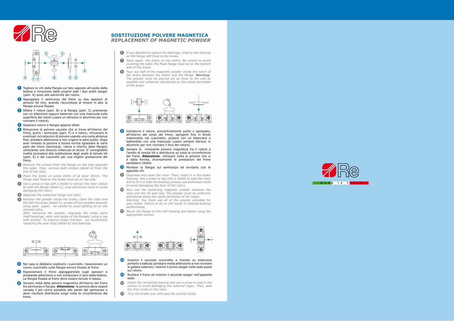
Inserire il secondo cuscinetto e tramite un bilanciere portarlo a battuta (prestare molta attenzione a non rovinare le gabbie esterne); inserire il primo seeger nella sede posta sul rotore.
Ruotare il freno ed inserire il secondo seeger nell’apposita sede.
Insert the remaining bearing and use a press to seat it (be careful to avoid damaging the external cage). Then, seat the first circlip on the rotor.
Turn the brake over and seat the second circlip.
Togliere le viti della flangia sul lato opposto all’uscita della bobina e rimuovere dalle proprie sedi i due anelli seeger (part. A) posti alle estremità del rotore.
Appoggiare il semicorpo del freno su due spessori di almeno 50 mm, avendo l’accortezza di tenere in alto la flangia ancora fissata.
Sfilare il rotore (part. B) e la flangia (part. C) premendo con un bilanciere oppure battendo con una mazzuola sulla superficie del rotore (usare un attrezzo in alluminio per non rovinare il rotore).
Separare rotore e flangia appena sfilati.
Rimuovere la polvere usurata che si trova all’interno del freno, pulire i semicorpi (part. F) e il rotore, rimuovere le eventuali incrostazioni di polvere usando una carta abrasiva fine; prestare attenzione a non ungere le parti pulite. Dopo aver rimosso la polvere è buona norma sgrassare le varie parti del freno (semicorpi, rotore e interno delle flangie) utilizzando uno straccio imbevuto di alcool. E’ consigliabile inoltre procedere alla sostituzione degli anelli di tenuta VA (part. E) e dei cuscinetti per una miglior prestazione del freno.
Remove the screws from the flange on the side opposite the cable. Then, remove both circlips (detail A) from the end of the rotor.
Place the brake on some shims of at least 50mm. The flange kept fixed to the brake must be on top side.
Use a press or tap with a mallet to extract the rotor (detail B) with the flange (detail C); (use aluminium tools to avoid damaging the rotor).
Separate the extracted flange and rotor.
Remove the powder inside the brake, clean the rotor and the half-housings (detail F), scrape off any powder deposits using sand paper; be careful to avoid getting oil on the cleaned sides.After removing the powder, degrease the brake parts (half-housings, rotor and inside of the flanges) using a rag with alcohol. To improve brake function, we recommend replacing the seal rings (detail E) and bearings.
Introdurre il rotore, preventivamente pulito e sgrassato, all’interno del corpo del freno; spingerlo fino in fondo inserendolo nel cuscinetto, aiutarsi con un bilanciere o battendolo con una mazzuola (usare sempre attrezzi in alluminio per non rovinare il foro del rotore).
Versare la rimanente polvere magnetica fra il rotore e l’anello di tenuta VA e distribuirla su tutta la circonferenza del freno. Attenzione: utilizzare tutta la polvere che vi è stata fornita, diversamente le prestazioni del freno sarebbero ridotte.
Montare la flangia sul semicorpo ed avvitarla con le apposite viti.
Degrease and clean the rotor. Then, insert it in the brake housing. Use a press or tap with a mallet to seat the rotor and to fit it in with the bearing (always use aluminium tools to avoid damaging the bore of the rotor).
Pour out the remaining magnetic powder between the rotor and the VA seal ring. The powder must be uniformly distributed along the whole perimeter of the brake. Warning: You must use all of the powder provided for your brake. Failure to do so will result in reduced braking performance.
Mount the flange on the half-housing and fasten using the appropriate screws.
SOSTITUZIONE POLVERE MAGNETICAREPLACEMENT OF MAGNETIC POWDER
AF F
A
B
E
C D
E
AF F
A
B
E
C D
E
AF F
A
B
E
C D
E
AF F
A
B
E
C D
E
AF F
A
B
E
C D
E
AF F
A
B
E
C D
E
AF F
A
B
E
C D
E1
2
3
45
1
2
3
4
5
6. Nel caso si debbano sostituire i cuscinetti, riposizionare un nuovo cuscinetto sulla flangia ancora fissata al freno.
7. Riposizionare il freno appoggiandolo sugli spessori e prestando attenzione a non schiacciare il cavo della bobina. La flangia fissata al freno deve essere tenuta in basso.
8. Versare metà della polvere magnetica all’interno del freno fra semicorpo e flangia. Attenzione: la polvere deve essere versata il più vicino possibile alle pareti del semicorpo e deve risultare distribuita lungo tutta la circonferenza del freno.
6
7
8
9
11
10
9
11
10
12
13
12
13
If you decided to replace the bearings, insert a new bearing on the flange still fixed to the brake.
Place again the brake on the shims. Be careful to avoid crushing the cable.The fixed flange must be on the bottom side of the brake.
Pour out half of the magnetic powder inside the notch of the brake between the stator and the flange. Warning: The powder must be poured out as close to the wall as possible and uniformly distributed on the whole perimeter of the brake.
m a d e i n I t a l y
6
7
8

Re S.p.A.Via Firenze 3 I 20060 Bussero (MI) ItalyT +39 02 9524301 F +39 02 95038986E [email protected]
w w w . r e - s p a . c o m
w.catiamassaro.it
ELEFLEX-I-GB-02/09
m a d e i n I t a l y


