

HAL Id: hal-01239318https://hal.archives-ouvertes.fr/hal-01239318
Submitted on 7 Dec 2015
HAL is a multi-disciplinary open accessarchive for the deposit and dissemination of sci-entific research documents, whether they are pub-lished or not. The documents may come fromteaching and research institutions in France orabroad, or from public or private research centers.
L’archive ouverte pluridisciplinaire HAL, estdestinée au dépôt et à la diffusion de documentsscientifiques de niveau recherche, publiés ou non,émanant des établissements d’enseignement et derecherche français ou étrangers, des laboratoirespublics ou privés.
Functional tolerancing: Virtual material condition oncomplex junctions
Robin Chavanne, Bernard Anselmetti
To cite this version:Robin Chavanne, Bernard Anselmetti. Functional tolerancing: Virtual material condition on complexjunctions. Computers in Industry, Elsevier, 2012, �10.1016/j.compind.2011.10.004�. �hal-01239318�

Functional tolerancing: virtual material condition on complex junctions
Robin CHAVANNE
Bernard ANSELMETTI
LURPA ENS-CACHAN, Université Paris Sud 11
Abstract: In industry, functional tolerancing of mechanisms is today more and more based on
ISO GPS (Geometrical Product Specification) and ASME standards. In this context, the CLIC
method (french acronym for “Cotation en Localisation avec Influence des Contacts”) has been
developed in our laboratory since 1998. The current standards are incomplete to specify
complex shapes, for example to define a datum reference frame on these surfaces. Using
specific examples, the present paper outlines six proposals as possible extension of standards
of tolerancing to describe the functional need for these links. Two main propositions are
developed, the material conditions on complex surfaces and the definition of a new
association criterion. Tolerance analysis models are presented; they must be consistent with
respect to proposed functional specifications.
Keywords: Functional dimensioning and tolerancing, tolerance analysis, GPS standards,
complex links, virtual boundary
1. Scientifical context The CLIC method [1] enables to elaborate a functional tolerancing based on notion of virtual
boundary and a three dimensional tolerance analysis. Junctions between parts are described
according to precedence order with primary, secondary and tertiary links. Geometrical
functional requirements of the mechanism are imposed by the functional analysis. Intern
requirements can be automatically detected by feature recognition (requirement synthesis) or
imposed by the designer. Functional tolerancing relative to a given requirement is generated
for each requirement (specification synthesis). Next, an equation is established to determine
the effect of these tolerances on each functional characteristic (tolerance analysis). The set of
equations allows then optimizing the tolerances and nominal dimensions parts in order to
decrease the manufacturing cost (tolerance synthesis).

Tolerancing of influential parts
Variation of CAD nominal models
Setting-up of each part
Generation of requirements,
definition of other requirements
Optimization of tolerances
Functional
specifications
Variations
of nominal
models
CAD model of mechanism import
Part assembly
Result of tolerance chains
Requirement synthesis
Tolerance analysis
Tolerance synthesis
Figure 1: Process flow of CLIC approach
A demonstrator enables to study many mechanisms, taking into account part defects and
clearances between parts. However, the studied junctions in these mechanisms are simple and
composed of planes or cylinders.
The objective of this work is to extend the CLIC method to complex links composed of
prismatic surfaces or free surfaces. It is necessary to propose a functional tolerancing for these
junctions in order to respect geometric requirements and to generate transfer equations. For
that, the calculation model should be consistent with respect for the definition of the
specification.
Several extensions will be proposed to generalize the concept of virtual condition to complex
surfaces. Nowadays, these proposed specifications are out of ISO or ASME standards.
The second section reminds the tolerancing method for transfer on simple mechanisms, in
order to explain the necessity to add an orientation specification to a position specification
and the interest of virtual condition specification. One difficulty is underlined for the mobility
of the datum reference frame with least material virtual boundary.
The third section introduces the need of virtual condition on complex surface and proposes a
new specification which respects the independence rule.
Finally, the fourth section analyzes a link denoted “hybrid” constituted of both contact feature
and fitting feature for the same geometric entity. Therefore, it is necessary to use specific
writing with a new association criterion.
2. Basic transfers
2.1 Presentation of basic mechanism
In this paper, the approach will be illustrated by an elementary mechanism (fig 2) constituted
of two parts noted housing and body. Generally, a junction between two parts is realized by a
primary link, a secondary link and eventually a tertiary link. These links can be classified in
different type, planar surface, cylindrical surface, prismatic surface, surface of revolution,
spherical surface and complex surface. Each link is formed by one or several surfaces.
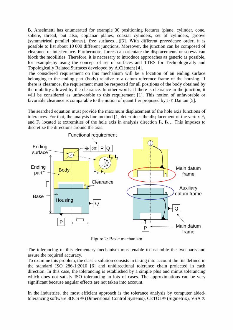
B. Anselmetti has enumerated for example 30 positioning features (plane, cylinder, cone,
sphere, thread, but also, coplanar planes, coaxial cylinders, set of cylinders, groove
(symmetrical parallel planes), free surfaces…)[3]. With different precedence order, it is
possible to list about 10 000 different junctions. Moreover, the junction can be composed of
clearance or interference. Furthermore, forces can orientate the displacements or screws can
block the mobilities. Therefore, it is necessary to introduce approaches as generic as possible,
for example,by using the concept of set of surfaces and TTRS for Technologically and
Topologically Related Surfaces developed by A.Clément [4].
The considered requirement on this mechanism will be a location of an ending surface
belonging to the ending part (body) relative to a datum reference frame of the housing. If
there is clearance, the requirement must be respected for all positions of the body obtained by
the mobility allowed by the clearance. In other words, if there is clearance in the junction, it
will be considered as unfavorable to this requirement [1]. This notion of unfavorable or
favorable clearance is comparable to the notion of quantifier proposed by J-Y.Dantan [5].
The searched equation must provide the maximum displacement of the hole axis functions of
tolerances. For that, the analysis line method [1] determines the displacement of the vertex F1
and F2 located at extremities of the hole axis in analysis direction f1, f2… This imposes to
discretize the directions around the axis.
t P Q
Functional requirement
Main datum
frame
Auxiliary
datum frame
Body
Main datum
frame
Ending
surface
Clearance
f1, f2
Housing
Ending
part
Base
F1, F2
Q
P
P
Q
Figure 2: Basic mechanism
The tolerancing of this elementary mechanism must enable to assemble the two parts and
assure the required accuracy.
To examine this problem, the classic solution consists in taking into account the fits defined in
the standard ISO 286-1:2010 [6] and unidirectional tolerance chain projected in each
direction. In this case, the tolerancing is established by a simple plus and minus tolerancing
which does not satisfy ISO tolerancing in lots of cases. The approximations can be very
significant because angular effects are not taken into account.
In the industries, the most efficient approach is the tolerance analysis by computer aided-
tolerancing software 3DCS ® (Dimensional Control Systems), CETOL® (Sigmetrix), VSA ®

and eM-TolMAte ® (Siemens PLM) which are often based on Monte Carlo methods. For
that, the designer has to choose geometric specifications applied on parts. The software
simulates then a population of components with defects generated by Monte Carlo simulation
and assemblies virtually parts. The desired characteristic is measured on final assemblies,
which allows estimating the result of the tolerance chain in worst case or in statistic. The
quality of these results depends on chosen specification, junction model and different
adjustments for random number generator.
Scientific approaches can be classified into four categories.
An easy solution is to model the junction by punctual contacts which form isostatic links
(MECAmaster) [7]. The deviation on each vertex represents the clearance effect and location
deviation of the bearing surface. So in links with clearance, the designer has to determine
contact points between parts function of the studied requirement. The model depends thus on
the studied requirement and on chosen analysis direction.
Several authors consider that all surfaces of link have orientation and location defects. Real
surfaces are modeled by substituted ideal surfaces (form defect is not taken into account)
which have an orientation and location deviation relative to the nominal surface defined in
CAD model [8], [9]. For example, the deviation of a plane is expressed function of three
parameters, two rotations and one translation. A hexagonal link with six planes imposes
consequently 18 parameters. The mobility of the part is modeled by the six degrees of
freedom, which enable to calculate the displacement of ending surface vertexes.
Constrains of mating impose constrains between these parameters. The derived relationships
show influent deviations relative to the requirement. The designer must then choose
specification and tolerance values which permit to control these influent deviations, which
allows calculating searched displacements.
Systems of equations can be very complex. M. Giordano [10] and D. Tessandier [11] present
results with domains and polytopes, but this can be complex with a great number of
parameters.
The third approach consists in simulating local defects of surfaces. J.K Davidson depicts the
surface in the form of T-Map® [12]. Samper [13] suggests a modal model which permits to
parameterize the form defects. In both cases, defects must be generated in order to determine
contact points between the pair of surfaces.
The fourth approach is based on boundary conditions defined in the standard ISO 2692 [14]
and ASME 2009 [15]. The major interest is to consider the assembly with perfect form part, at
maximum material to check if the assembly is possible or at least material to determine the
maximum displacement of the ending surface. The fundamental hypothesis supposes that the
displacement will be greater when links are at least material conditions. This approach is very
efficient to compute the greatest displacement in worst case but does not allow good statistic
evaluation.
The CLIC method refers to this last approach. The tolerancing proceeds in two steps. The
tolerancing of junction surfaces enables to create the main datum reference frame on
positioning surfaces and an auxiliary datum reference frame on support surfaces. Form
specifications assure the quality of the contact. Specifications at maximum material condition
guarantee the assembly. In the second step, positioning surfaces are positioned each relative to

the others, by locating each surface of the auxiliary datum reference frame with regard to the
main datum reference frame, this using the concept of least material condition for fitting
features of the junction and finally by locating the ending surface relative to the main datum
reference frame of the ending part.
2.2 Transfer with a surfacic link
The figure 3 illustrates a basic mechanism composed of a body and a housing. Plane A of the
body is in contact with plane D of the housing. A location requirement imposes to control the
maximum height at vertex F. The distance between F and contact face is L. Orientation and
location specifications are used to specify the contact surface D of the housing. The real
surface has to remain inside these two tolerance zones. The datum plane A of the body bears
down the real plane of the housing.
The contact hypothesis considers that the datum plane A of the body remain in the orientation
and location tolerance zones of housing. Measurements done by Radouani [16] show that this
hypothesis is not perfectly respected and there is an overtaking and a possible interference
which depends on the sum of flatness defects or contact surfaces. Generally, the influence of
form defects is neglected.
t 1h
t1h P
A
t 2h
F’
E
L
d(F’, f )
t1b A
t2h P
body
housing
F
F’
f
Hm
axi F’L
P P
P
A
D
t P
Figure 3: Basic tolerance chain with contact surfaces
The displacement of the vertex F in the direction f is equal to the displacement of the point F’
which belongs to the datum plane A:
d(F, f) = d(F', f)= t1h/2 + t2h.L/E (1)

If there was not orientation specification, the inclination of A would be bigger. The
displacement of F would be:
d(F, f) = d(F', f)= t1h/2 + t1h.L/E (2)
Therefore, the interest of this orientation specification with t2h < t1h is to control the angularity
of the datum plane A in the location tolerance zone and to limit thus the displacement of the
vertex F.
2.3 Transfer with link with clearance
The figure 4 illustrates a basic mechanism composed of a shaft assembled in the housing with
clearance. The studied requirement is a location of the ending cylindrical surface in order to
control the position of the point F relative to the datum plane P of the housing.
Both diameter specifications with envelope requirements impose maximum material boundary
to ensure the assembly of these two parts.
The new hypothesis in this case is that the displacement of the point F in a direction f will be
maximum when cylinders A and D will be at least material conditions and when the hole D
will be inclined in the tolerance zone. The tolerancing will be at least material condition.
The cylinder A of the shaft at least material condition is a cylinder with a diameter dv = d -
td/2. The point F is located on the axis of this cylinder.
The hole D of the shaft is a cylinder with a diameter Dvo = D+tD/2 + t2h parallel to P which
must be included in the position virtual boundary with a diameter DvL = D+tD/2 + t1h.
The classical hypothesis supposes the least material boundary of the datum A of the body can
move inside both least material conditions of the housing.
D ± tD/2E L
dv=d-td/2
D
vo
D
vL
F
d(F, f )
t2h P
t1h P
Hm
axi
t1s A
shaft
housing
Ff
L
P P
d ± td/2
A
t P
PE
E
L
L
L
M
Figure 4: Basic tolerance chain with cylindrical link and clearance

This model lets to simulate the displacement of the cylinder A in the hole D in order to
determine the displacement of the point F in the direction f.
d(F, f) = (DvL - dv)/2 + (Dvo - dv).L/E (3)
Indeed, the cylinder A can lean cause of the diameter differences of virtual boundaries (Dvo -
dv) and translate of the half of the difference (DvL - dv) at point M.
Without orientation specification, the inclination of A would be bigger. The maximum
displacement of F would be:
d(F, f) = (DvL - dv)/2 + (DvL - dv). L/E (4)
Therefore, the interest of this orientation specification with t2h < t1h is to control the angularity
of the datum cylinder A in the location tolerance zone and to limit thus the displacement of
the point F.
This example shows the importance of the least material boundary concept to calculate the
resultant of the 3D tolerance chain. Moreover, if the real cylinder D is smaller than the least
material cylinder, the housing will be acceptable, with position and orientation deviations
bigger than the tolerance value.
In this last example, P datum reference is fixed, without mobility allowed by material
modifier. Next section focuses on the case of a floating datum reference obtained with least
material boundary.
2.4 Transfer with floating datum reference
When the link of the support has clearance, the datum of this link has to be considered at least
material boundary. The virtual least material cylinder is thus floating in the real cylinder of
the real part. This may be a problem because the orientation virtual boundary and the position
virtual boundary are independent. To study this behavior, the figure 5 shows a stacking of
three parts composed of two serial cylindrical links.
The primary cylinder A of the shaft is assembled with interference in the hole E of the body.
The primary cylinder B of the body is assembled with clearance in the hole C of the housing.
Both studied requirements R1 and R2 are locations of points F1 et F2 with respect to the datum
reference frame PQ. For this demonstration, the requirement R1 will be analysed in the
direction f1 and R2 in the direction f2.

F2
t1s A
s1 ± t2s/2
s2 ± t3s/2
t2b B
t1b B
b1 ± t3b/2
b2 ± t4b/2
t1h P Q h1 ± t2h/2
Q
F1
t1sA
s1 ± t2s/2
f2
f1
(S3)
(S4)
t2h P Q
shaft
body
housing
Dmini
Dmaxi
P
B
E
C
A
P
Q
(E1)
(E2)
(S1)
(S2)
t2 P Q
(R2)
t1 P Q
(R1)
(S5;S6)
E
L
E L
L
L
L
L
E
E
E
E

Figure 5: Mechanism with two primary cylindrical junctions
In figure 5, the tolerancing established with the CLIC method is similar to the figure 4. The
envelope requirements guarantee the assembly of parts for the primary cylinders. The study of
the two requirements imposes position specification between surfaces. There is not clearance
for the link between the shaft and the body. Therefore, there is not material modifier on the
datum A for shaft specifications S1 and S2 neither on the toleranced surface of S3 and S4 for
the body. On the other hand, the link between the body and the housing has clearance.
Consequently, datum for specifications S5 and S6 of the body and toleranced surface of S5
and S6 of the housing are at maximum material condition.
For the position specification S3, the virtual boundary of the datum B is a cylinder with a
diameter value b2 - t4b/2 which must be included in the real cylinder B. The axis of the
cylinder E must be contained in a cylinder of diameter value t1b coaxial to this virtual
boundary.
For the orientation specification S4, the virtual boundary of the datum B is a cylinder with
diameter value b2-t4b/2 which must be contained in the real cylinder B. The axis of the
cylinder E must be contained in a t2b diameter cylinder parallel to this virtual boundary.
Dr
F1
dmini
t1b
t2b
O
H
E
e
h
amaxi
D
a
Figure 6: Three-dimensional model for displacement of F1
The figure 6 shows the configuration which presents the maximum displacement of the point
F1 in the direction f1.
The body at least material condition is composed of the cylinder B with diameter value dmini =
b2-t4b/2 inclined in the hole C of the housing of an angle amaxiD - dmini)/E. The axis of the
hole E is simultaneously in the orientation tolerance zone (diameter t2b) which is parallel to
the virtual boundary of B and in the position tolerance zone (diameter t1b) which is centered to

the virtual boundary of B. The primary link shaft/body which is with interference, the datum
A of the shaft is coincided to the axis of E. The maximum displacement of the point F1 is:
d(F1, f1) = D - dmini).H/Et1b/2 + t2b.h/e (5)
If the diameter Dr of the real cylinder B of the body is bigger than b2 - t4b/2, the inclination of
this cylinder is smaller than amaxi in the cylinder C of the housing. On the other hand, the
working deviation for the body is bigger. The body remains conform if the real axis of the
cylinder E is contained in the two tolerance zones defined relative to the least material
boundary with diameter value b2 - t4b/2, which must be contained in the real cylinder B. So,
the figure 6 shows well this cylinder B of diameter value Dr containing least material
boundary of the cylinder B, with the two tolerance zones.
The maximum displacement of the point F1 is identical. Then the relationship (5) is
confirmed.
Practically, with a Dr diameter cylinder B bigger than the least material condition, the
clearance between the housing and the body decreases. That cuts down the angular deviation
a. This reduction enables to allow a bigger position deviation of the axis E of the body with
respect to cylinder B. This gain on the tolerance is the main advantage of the using of the
virtual least material condition on the datum.
Finally, the maximum displacement of the point F1 in the analysis direction f1 is the same for
a cylinder B at least material and for a cylinder B with a bigger diameter. The calculus
hypothesis which considers that the displacement is maximum when the parts are at least
material condition, is valid.
F2
dmini
t1b
t2b
amaxi
H
E
e
hO
D
Figure 7: Three-dimensional model for displacement of point F2 with B at least material
condition

The figure 7 shows the configuration of conform parts which simulate the maximum
displacement of the point F2 in the analysis direction f2 considering the cylinder B at least
material condition. The datum B is inclined in the hole C of an angle value amaxiD -
dmini)/E. The axis of the hole E must simultaneously be contained in the orientation tolerance
zone (diameter t2b) which is parallel to the least material boundary of B and in the position
tolerance zone (diameter t1b) which is centered to the least material boundary of B. As the
primary link shaft/body is with interference, the datum A of the shaft is coincided with the
axis of E. The maximum displacement of the point F2 is then :
d(F2, f2) = D - dmini).H/Et1b/2 + t2b.h/e (6)
The relation is the same than (5).
The figure 8 shows the maximum displacement of the point F2 with conform parts but with a
diameter dr for the cylinder B lightly superior than minimal diameter dmini. The inclination of
his cylinder is D - dr)/E.
The conform parts which provide the maximum displacement of the point F2, are in a very
particular configuration permitted by the independence of specifications S3 and S4.
- For the location specification S3 (Fig 5), the axis 1 of the least material boundary of
the datum is a cylinder of diameter value dmini = b2 – t4b/2, inclined of dr - dmini)/E
in the anti-trigonometric sense, inside real B cylinder (fig 8).
- For the orientation specification S4, the axis 2 of the least material boundary of the
datum is a cylinder of diameter value dmini = b2 – t4b/2 inclined of dr - dmini)/E in
the trigonometric sense, inside real B cylinder The orientation tolerance zone of E is
parallel to 2. This inclination sense maximizes the displacement of the point F2. The
E axis is then leant of at2b/e
In this case, the maximum displacement of point F2 is:
d*(F2, f2) = F2F'2.f2= (F2M+MN+NF'2). f2 = (h – H).() + t1b/2 + .h
d*(F2, f2) = (2dr – D - dmini).(h - H)/E + t1b/2 + D - dmini).h/E + t2b.h/e (7)

dr
Maximum deviation with dmini :
Maximum deviation with dr :
1 : Axis of virtual boundary
to respect S3 (t1b)
2 : Axis of virtual boundary
to respect S4 (t2b)
3 : Critical axis of E with dmini
4 : Critical axis of E with dr
F2
dmini
dmini
2 1
3
4
O
t1b
t2b
z
MN
H
E
e
h
amaxi
D
F’2
location
tolerance zone
orientation
tolerance zone 1
2
B
Figure 8: Three-dimensional model for displacement of F2 in general case
The obtained displacement by relation (7) is higher than the one calculated considering B at
least material condition given by relation (6). The difference is:
d*(F2, f2) - d(F2, f2) = 2(dr - dmini).(h – H)/E (8)
The authorized displacement for F2 by the specifications is then higher if diameter dr is large,
i.e. when cylinder B is not at least material condition. Then, it contradicts the usual
hypothesis. This phenomenon comes from the different positions of least material boundaries
for the specification S3 and S4 (figure 5). It appears when floating reference is located
between the analysis point (F2) and the surface of link (E).
2.5 Hypothesis analysis for transfer at least material
Although it is intuitively obvious, the hypothesis considering that the maximum displacement
is obtained with parts at least material condition is not verified. This is due to the
independence principle with a double specification: the orientation tolerance zone is not
parallel to the location tolerance zone. The orientation specification is no more efficient, it
does not limit the inclination of the axis in the location tolerance zone.
Four solutions can be discussed to take into account this phenomenon.
1. To keep the proposed tolerancing: The additional term must be taken into account in
the calculus of the resultant. This solution would lead to a paradox because the

displacement of the point F2 is maximum when the datum is at maximum material
condition, this is conflicting to the classic notion of mobility due to clearance.
2. Datum without modifier: Specifications would be stricter because they do not permit
to benefit from the virtual boundary mobility when parts are not at least material
condition.
3. Removal of orientation specification: In this case, point F2 is:
d(F2, f2) =D - dmini).H/E t1b/2 + t1b.h/e (9)
This formula is equivalent to (6) with t1b = t2b. The location tolerance t1b that limits the
inclination has to be lower than the one obtained with both specifications for the same
displacement of point F2. The single specification is then more restrictive.
4. Least material boundary common to specifications S3 and S4. With actual standards,
this solution is not directly applicable. A commentary as “Common least material
boundary on the reference” has to be added.
The fourth solution seems to be the less restrictive and the most coherent with the tolerancing
method which limits the orientation deviation inside the position tolerance zone.
2.6 Proposal of a new tolerancing concept
A new tolerancing concept has to be proposed in order to apply the fourth solution.
Proposal 1: Composed specification
A “composed” specification is the association of several specifications dealing with a single
toleranced surface (simple element, group, common zone …) with a single datum reference
frame. The toleranced surface has to simultaneously belong to all the tolerance zones defined
relatively to the single datum reference frame.
t2b
t1bA
t2b
t1bA B CL L L
Figure 9: Specification with single datum reference frame.
In case of a datum with a maximum or minimum material modifier, the toleranced surface has
to belong simultaneously to all tolerance zones defined relative to a virtual boundary of the
unique datum reference frame.
This writing does not contradict to the independence principle, because in fact, the two
specifications form a single one composed of two tolerance zones relative to a common datum
reference frame.
This concept is very well suitable in order to combine an orientation specification and a
position specification, on the same tolerance surface, with the same datum reference frame.
If the functional point is F1, the worst case is obtained in the case of the figure 6. It is useless
to approve the writing of the figure 9, because this could lead to reject conform parts which
respect the functional requirement.
The concept proposed figure 9 is near to the notion of composite tolerancing in ASME
standard, which associates an orientation specification and a position one. On the other hand,
this standard does not mention particular properties about datum reference frame.

This section has shown the interest to add an orientation specification to the position
specification in order to control the influence of angular defects in the primary link in case of
important overhang. Unfortunately, in current standards, this strategy is not suitable for datum
with clearance. Four solutions are so proposed, adding over displacement, only position
specification, datum without material modifier or comment to impose a common least
material boundary for both specifications.
3. Virtual boundary on complex surfaces
3.1 Introduction
The tolerancing at maximum material condition guarantees the assembly of parts with
clearance. The tolerancing at minimum material condition facilitates the calculation of the
tolerance chains result.
In the current ISO standards [14], the maximum or minimum material modifiers are
associated to the local dimensions and are exclusively useful for fitting features, cylindrical
features or symmetrical parallel plane features (a groove for example).
However, lots of mechanisms are composed of more complex junctions with a functional
clearance for which the notion of virtual boundary at least or maximum material condition can
be absolutely used. This section presents different junctions and some proposals to extend
current standard.
3.2 Local dimensions
In the elementary mechanism of the figure 10, the junction is constituted of a primary plane
and a secondary cylinder. The requirement R1 is a location of the extremity of the body with
respect to the datum reference frame PQ. On the body, this cylinder is in fact composed of
three cylindrical sectors.
F f
housing
body
(E1)
Section of the body
P
Q
t P Q
Figure 10: Secondary feature composed of several cylindrical sectors

The figure 11 shows the proposed tolerancing for the body considering B as a cylinder.
- The flatness (S1) of the primary plane A guarantees a good contact with the housing.
- The diameter specification (S2) is a problem because the notion of local dimension does not
exist on the body. Indeed, there are not two points face to face on the cylinder in order to
measure the local diameter. The envelope requirement can be certified with a 17,98 diameter
gauge.
- The specification of perpendicularity at maximum material condition can be perfectly
certified with the help of a 18 diameter gauge flattened on the plane A or with a measurement
machine.
The specification of perpendicularity S3 guarantees the assembly when the contact plane on
primary plane is assured. On the other hand, the envelope requirement ensures a larger
clearance to facilitate the assembly of the body in the housing.
For the specifications S4 and S6, the datum B appears alsowith a modifier. According to the
standard ISO 2692-2007, the diameter of the least material boundary (S4) is equal to the
minimum diameter of B (17.92), and, the diameter of the virtual boundary at maximum
material (S6) is equal to the maximum diameter of B (17.98).
t1b A B
3x 17.95 0.03
0.02 CZ A (S3)
(S4)
E
A B 0
4x 6.3 0.3 (S5)
(S6)
B
(S2)
0.03 (S1)
A
L
M M
M
Figure 11: Tolerancing considering B as cylinder
This tolerancing satisfies perfectly the functional need to assure the assembly and the
requirement R1. Nevertheless, it is problematical in a sense that the local dimensions are not
measurable.
In fact, this example reveals that it is not necessary to measure the local dimensions if the
tolerancing is complete, with a tolerancing of the cylinder B at maximum material condition
and if B is used as a datum at least material condition. The writing of the diameter is only
imposed by the writing way of the virtual boundary diameter in current standard. For the
specification S2, it would be possible to put the diameter between brackets, this means that

the value would be just given to determine the size of virtual boundaries but not to certify the
local dimensions.
To solve this problem, the standard ASME Y14.5-2009 page 61 proposes to indicate between
square brackets directly the size of the virtual boundary on the datum inside the feature
control frame. The specification S4 could be written according to the figure 12
Lt1s A B [17.92]L(S4)
Figure 12: Size of virtual boundary on datum frame in ASME standard
Basing on this concept, the rule would be extended to the toleranced surface.
Proposal 2: Size of virtual boundary between square brackets
With a maximum or least material modifier on the tolerance surface or on a datum, the size of
the virtual boundary can be given directly between square brackets in the feature control
frame. With this writing, the envelope requirement can be expressed by a straightness. The
specifications S2, S3, S6 would be thus written according to the figure 13.
[18] CZ A(S3)
[17.98] CZ(S2)
[6] A B [18](S6)
MM
MM
MM MM
Figure 13 : Size of the virtual boundary in specification
This writing would perfectly respect the independence principle. The direct indication of the
size of the virtual boundary on the datum would avoid the ambiguities which has been
revealed in the standard ISO 2692 edited in 2007. It would be useless to put a specification of
diameter with the notion of local dimension which is a problem. In CAD systems, it does not
impose to define parts with medium dimension.
3.3 Maximum and least material on free surfaces
The cylindrical surface B of the body can be considered like a free surface, but the use of
material modifiers is not allowed with the current ISO standards. So, the figure 14 is a new
proposal which is not described in ISO standards based on the specifications of complex
surfaces.

t1s A B 0.06 L (S4)
0.1 CZ A
3x
0.06 CZ (S2)
(S3)
A B 0.1 0
4x 6.3 0.3 (S5)
(S6)
x
z
B
0.03 (S1)
A
MM
M
M
Figure 14: Tolerancing considering B as complex surface
In the figure 14, the nominal surface B is constituted of three cylindrical sectors of nominal
diameter value 17.95. Without the maximum material modifier, the specification S2 is
completely defined in standards. The tolerance zone is the envelope of a 0.06 diameter sphere
which center covers the nominal surface (17.95 diameter cylinder). The tolerance zone is thus
limited by two cylinders respectively of diameter value 17.98 and of diameter value 17.92.
The real surface must be contained in the 17.98 diameter cylinder which defines the
maximum material boundary and corresponds exactly to the envelope requirement of the
figure 11. Inversely, 17.92 diameter cylinder must be contained in the material, which
corresponds to the virtual boundary at least material for the requirement S4 of the figure 11.
Proposal 3: Virtual boundary at maximum or at least material condition on a surface
For a specification or a datum on a surface defined by the intrinsic nominal characteristics and
by basic dimensions, the tolerance zone is defined by the envelope of a sphere of diameter
equal to the tolerance and which center covers the nominal surface.
With the maximum material modifier, only the outside boundary must be preserved. This
surface is the maximum material boundary. The real surface must respect this virtual
boundary.
With the least material modifier, only the inside boundary must be preserved. This surface
constitutes the least material boundary. This virtual boundary must be contained in the
material.
In the figure 13, the value between square brackets gives the size of the virtual boundary. For
the complex surfaces, the notion of local dimension does not exist. Values proposed figure 15
correspond to the classic notion of tolerance and can be distinguished because this value is not
between square brackets. It would be possible to define the offset value of the surface relative
to the nominal surface. This would enable a negative offset. However, this definition would
be new and different from the classic notion of tolerance zone with a coefficient 2 which can
create lots of interpretation or measurement problems.
The figure 15 illustrates the proposed explanation for specifications of the figure 14.

Maximal material
boundary: 17.98
(S2)
Nominal cylinder
17.95
0.06 CZ
Least material
boundary: 17.92
Nominal cylinder
17.95
t1s A B 0.06 (S4)0.1 CZ A (S3)
Maximal material
boundary: 18
Nominal cylinder
17.95
LMM
Figure 15: Définition of virtual boundaries
For the S2 specification, the maximum material modifier on the toleranced surface just incites
to take only the 17.98 diameter cylinder into account. So the real part must be contained in
this boundary which is the maximum material boundary for the form specification of this part.
The S3 specification is a specification location of the surface, but as the datum is a simple
plane, degrees of freedom in rotation around z and in translation on axis x and y are free. So,
this specification is identical to an orientation specification and corresponds perfectly to the
perpendicularity S3 of the figure 11.
For the specification S4, the datum B is also applied on the surface. The least material
boundary is defined by the inside boundary generated by a sphere whose center covers the
nominal surface. The diameter of the sphere is indicated on the right hand to the datum in the
feature control frame. For the specification S4, the virtual boundary is so a 17.92 diameter
cylinder which has to be contained in the real surface.
The maximum material boundary ensures the assembly and the least material boundary
assures the accuracy of the mechanism. With such coherent tolerancing, there are no more
local dimensions to inspect.
3.4 Prismatic junction
In the basic mechanism of the figure 16, the junction is composed of a primary prismatic link
with clearance and a secondary plane. The requirement R1 is a location of the conic surface of
the body relative to the datum reference frame PQR. This requirement must be respected for
all configurations permitted by the mobility dues to the clearance.

t P Q R
body
housing
(R1)
R
P
CC
Q
Figure 16: Basic mechanism with prismatic primary datum
The tolerancing proposed by the CLIC method is composed of three specifications,
represented in figure 17:
-S1, S2: assembly requirements of the primary surface (at maximum material condition)
-S3, S4: quality of the contact between the two secondary planes knowing that the primary
link is assured by the prismatic link with clearance.
- S5, S6, S8: position specifications to respect the studied requirement.
-S7: orientation specification to limit the inclination of the surface D in the position tolerance
zone of S6.

t1b A t2b B
t5b
t3b A t4b
(S1)
(S8)
(S3)
t1h P Q
(S2)
(S6)
(S7)t2h P Q (*)
t3h
t4h D t5h (S4)
t6h P Q R (S5)
Q
P
R
A
B
LL
LL
LL
LL
LL
MM MM
D
(*): orientation only
Figure 17: Tolerancing of the housing and of the body
The tolerancing of the housing shows that three specifications of form, orientation and
position must be applied on the same surface. In the current state of the standard ISO, the
unique useful symbol is the symbol , which makes impossible to distinguish the orientation
specification of the position specification relative to the same datum reference frame. It is
necessary to put a comment “orientation only” next to the specification S7.
To solve this difficulty, different authors proposed to use classic symbols of orientation
and position considering that the graphic representation indicates that the
toleranced surface is a complex surface. This approach seems to be unacceptable, because it
would be impossible to distinguish if the specificed element is the surface or the axis of the
surface.
For example in the figure 17, for the location S8, the symbol woul be acceptable, because
the arrow of the specification is not in front of the arrow indicating the angle of the cone or
the diameter of the gauging plane. So the toleranced surface is the conic surface. On the other
hand, this analysis is no more possible with the tolerancing on the 3D model, for example
with the workshop FTA of CATIA® by Dassault Systèmes where the basic dimensions are no
more represented. The element pointed by the specification is always the surface of the part.
The tolerance element is the axis with the symbol or the surface with the symbol . On
the other hand, with material modifiers, the toleranced element is inevitably the surface.
It is important that future standard proposes a specific orientation symbol for complex
surfaces. The standard XP E 04-562 [17] has proposed for example the symbol ori. This
paper does not propose voluntarily a new symbol in order to avoid future ambiguities.
In complement of the proposal 3, it is necessary to specify the definition of form, orientation
and position specification with modifiers.

Proposal 4: Form, orientation and position at maximum or least material condition
The symbol without datum reference frame indicates a form specification. The virtual
boundary can move according to the six degrees of freedom in order to certify the real
surface.
The symbol with a datum reference frame (without comments) indicates a position
specification. The virtual boundary can move only according to the degrees of freedom of the
datum reference frame in order to certify the real surface.
The symbol with a datum reference frame and the comment « orientation only » (or
equivalent) indicates an orientation specification. The virtual boundary can move according to
the three translations and the degrees of freedom of the datum reference frame in order to
certify the real surface.
These definitions allow establishing a rule of tolerancing. If the datum reference frame has
degrees of freedom in rotation, to add an orientation specification to a position specification in
order to master the angular effects imposes a composed specification in the sense of the
proposal 1, in order to guarantee that the two tolerance zones are well parallel.
The figure 18 shows the minimum clearance allocated by form specifications S1 and S2 at
maximum material condition represented in figure 17.
Nominal surface
BodyHousing
Nominal surface
Virtual boundary at
maximum material
Virtual boundary at
maximum material
(S2)t3h M t5b (S1)
A
M
D
Minimal clearance
t5b/2t3h/2
Figure 18: Minimal clearance between maximal material boundaries
For the requirement R1 (fig 16), the accuracy of the primary link will be critical when the
parts are at least material condition. On the shaft, this requirement imposes the specification
S8 defined in the figure 19. The least material boundary of the primary datum A is an offset of
the nominal surface with the value t2b/2. This virtual boundary must be contained to the
material of the real part.
The secondary datum B is a plane perpendicular to this virtual boundary tangent to the real
plane. The difference between the least material boundary of the primary datum and the real
surface let a residual mobility in order to introduce the real cone in the tolerance zone. The
secondary plane must be tangent but not constrained with a Tchebitchev criterion which
minimizes the maximum distance on the secondary plane.

Nominal
surface
t2b/ 2
Least
material
boundary
t1b A t2b B LL
B
A
Figure 19: Floating datum reference frame of the shaft
On the housing, this requirement R1 imposes a position specification S6 with tolerance value
t1h and an orientation specification of tolerance value t2h with t1h > t2h. The least material
boundary is located relative to the datum reference frame PQ. The orientation virtual
boundary (S7) is smaller and orientated relative to the datum reference frames PQ. The figure
20 shows the virtual housing which gives the maximum displacement for a vertex F in the
direction f. The hole is defined by the orientation least material boundary moved in the
direction f, but contained in the location least material boundary. The analysis line being
pointed at the top, the surface E is supposed coincided with the superior limit of the location
tolerance zone of S5 (fig 17).
The tolerance chain transfer is built with the shaft at least material condition inclined in the
orientation least material boundary of the housing to maximize the displacement of the point
F. The contact plane B will be tangent to the surface E.

Ff
t 6h
B
AD
E
Least material
boundary in
position (S6)
Least material
boundary in
orientation (S7)
t1h P Q
(S2)
(S6)
t2h P Q
t3h
Q
P
LL
LL
MM
D
Figure 20: Three dimensional transfer method based on least material model
The three-dimensional model of transfer imposes to study the mobility of a complex virtual
boundary in another one and to search contact points between these virtual boundaries.
Chavanne uses for that a geometric algorithm or a solver [18].
4. Hybrid junction
4.1 Basic mechanism with an hybrid prismatic junction
The figure 21 presents an basic mechanism with a prismatic link in z direction. In fact, the
body is in contact with the housing in the middle surface between J and K and is centered by
the two flanks IJ and KL.
The middle surface between J and K has a variable curve but is very flat and does not block
the degrees of freedom in translation according to x and in rotation around y. These two last
degrees of freedom are blocked by the flanks with a little mobility allowed by the clearance.
For the first approach, it would be possible to consider that the middle surface is a prismatic

surface which blocks geometrically all of five degrees of freedom. Then, the flanks have no
more role and can not be defined as secondary surface.
Consequently, the entire surface must constitute a primary link qualified of hybrid in the sense
of the double behavior (contact and clearance).
P
Q
t P Q
Body
HousingK
I L
J
y
x
Figure 21: hybrid prismatic link
The figure 21 presents the location requirement of the mark at the top of the body relative to
the datum reference frame PQ of the housing. The requirement R1 must be respected for all
positions permitted by the clearance.
4.2 Classic tolerancing of parts
The figure 22 presents the classic tolerancing of the two parts considering globally the entire
surface.
The form specifications S2 and S4 must ensure the quality of contact and the minimal
clearance between parts. The tolerance zones are centered relative to nominal surfaces. To get
the required clearance, it is necessary that nominal surfaces of the two parts are different on
the flanks. On the other hand, the nominal surfaces are identical for the middle contact
surface.
On the body, the ending surface must be located relative to a datum reference frame created
on junction surface A.
On the housing, the bearing surface D is located relative to the datum reference frame PQ. It
is not necessary to add an orientation specification in order to limit the inclination because
there is not overhang between the ending surface and the link surface.

t2b A
(S1)
t1b
A
(S2)
t1h
t2h P Q
PQ
(S3)
(S4)
least square
Figure 22: Classical tolerancing of parts
For the specification S1 of the body, standards ISO do not clearly give the definition of the
datum on a free surface. The least square criterion is thus indicated on the right hand of the
datum feature A. In this case, the datum is an identical surface to the nominal one associated
by the least square criterion to the real surface. This criterion minimizes the sum of the square
of each deviation and provides a datum perfectly defined, without allowing the mobility
corresponding to the clearance between the flanks.
This surface has light angle on the flanks. A datum reference surface identical to nominal
surface tangent to exterior material could be away in the real middle surface (fig 23). The
Tchebitchev criterion is not suitable for this type of surface.
Least square
datum
tangent
datum
Nominal surface
Figure 23: Datum with least square criteria and minmax criterion
4.3 Datum in a link with clearance
The mechanism of figure 24 is similar to the one of figure 21, with a primary plane and a
secondary link with clearance. The tolerancing applies the rules of the proposal 3.

Three requirements are taken into account by the proposed tolerancing:
Quality of the contact on the primary plane
Minimum clearance to guarantee the assembly of parts
Location of the mark relative to the datum reference frame PQ for all positions of
allowed by the clearance.
The chain transfer must take the maximum clearance into account between the least material
boundaries in order to share the tolerances. If the body is bigger than its least material
condition, the clearance will be smaller and it will be possible to accept shifted mark. This is
allowed by the datum reference frame at least material condition. (S5) t4b A B t3b
LL
B
A
t4h P
t1h
D
QP
t3h P QLL
t2h DMM
t1b
t2b AMM
(S1)
(S3)
(S6)
(S4)(S7)
(S2)
100100
99.999.9
Body
Housing
y
x
Nominal
surfaces
Minimal distance
Maximal distancet3b/2
Nominal distance0.05
t2b/2t2h/2
t3h/2
Figure 24: Tolerancing with primary plane and secondary slot
The good contact between the body and the housing is assured by the two form specifications
S1 and S2. The gap is the maximal distance between real surfaces when these surfaces are in
contact. So, the maximum gap between the two surfaces is the sum of the form tolerance
values.
Gap = t1b + t1h.
Supposing the body centered in the housing, the nominal distance between the nominal
surfaces is defined by basic dimensions:
Nominal distance = (100 – 99.9)/2 = 0.05.
As the part is symmetrical, the clearance is equal to the double of this distance.
The minimum distance between parts is assured by the specifications S3 and S4 which require
two maximum material boundaries, offset of t2b/2 for the body and offset of t2h/2 for the
housing.
The minimum distance between the flanks is then:
Minimum distance= nominal distance - (t2b + t2h)/2
The location requirement of the mark relative to the datum reference frame PQ requires the
position specification S5 on the body and the two locations S6 and S7on the housing.

For the specification S5 of the body, the primary plane datum is the tangent plane to the real
plane A minimizing the maximal distances. The secondary datum is defined by a virtual
boundary composed of two symmetrical parallel planes perpendicular to A and distant of t3b/2
to nominal surfaces. This virtual boundary must be contained inside the body surfaces B. The
toleranced element is the mark surface. This real surface must be contained in a tolerance
zone of wide value t4b theoretically located relative to the primary datum and the least
material boundary. The mobility allowed by the space between the virtual boundary and the
real surface B enables to move the mark surface in the tolerance zone.
On the housing, the specification S6 defines a least material boundary formed by two planes
offseted of t3h/2 relative to nominal planes. This virtual boundary must be inside the material.
The maximum distance between the flanks is so:
Maximum distance = Nominal distance+ (t3b + t3h)/2
4.4 Datum definition in a hybrid link
The figure 26 presents the proposed tolerancing to find the same behavior on the hybrid link.
The surface is restricted by letters I, J, K and L to isolate the middle surface and the flanks.
Each segment must be separately specified. In standards, the symbol "between" is written
under the feature control frame as in case (a) of figure 25.
t1b
A B
0,1
0,2
A B
B C
(a) (b)
Figure 25: restricted zone inside specification
The specification (b) of the figure 25 introduces a new concept to describe the limit of the
restricted zones inside the feature control frame.
Proposal 5: the indication A B located on the right hand of the tolerance value or on the
right hand of a datum limits the area of the considered surface. Several indications in the same
feature control frame allow modifying the characteristics of the tolerance zone in function of
the segment of the considered surface. All tolerance zones thus defined constitute a common
zone that must respect the toleranced surface.
This writing is necessary, because it is impossible to write these conditions with independent
specifications, particularly for form specifications or floating datum reference frames.

J K
(S3)
JKA
I L
t2b I J
K L
t4b A
LL
BB
(S1)
P
Q
MM
J
I
K
L
K
L
t1b
J K
I JK L
t3b
t4h
t3h LL I JK L P Q
J K
I J
K L
J Kt1h
t2h MM
(S4)
(S2)
LLt3b
t2bMM
t3h LL
t2h MM
Nominal
surfaces
Minimal distance
Maximal distance
Nominal distance
t3b/2
0.05
t2b/2t2h/2
t3h/2
Figure 26 : Tolerancing of hybrid links
The good contact between the body and the housing is assured by the two form specifications
S1 and S2 limited to the middle segment between J and K. The maximum gap between the
two surfaces is the sum of the form tolerance values
Gap = t1b + t1h.
Supposing the body centered in the housing, the nominal distance between the nominal
surfaces is defined by nominal surfaces: the distance depends on the considered point.
The part being symmetrical, the clearance is about equal to the double of the minimal
distance.
The minimum distance between parts is assured by the specifications S1 and S2 which require
two maximum material boundaries, offseted of t2b/2 for the body and offseted of t2h/2 for the
housing.
The minimum distance between the flanks is so:
Minimal distance= nominal distance - (t2b + t2h)/2
The position requirement of the mark according to the datum reference frame PQ requires the
position specifications S3 on the body and S4 on the housing.
For the specification S3 of the body (fig 26), the datum reference is defined on the segment
between J and K and with a least material boundary on the flanks. This least material
boundary is offset of t3b/2 with regard to the nominal surfaces. This one must be contained
inside the body surfaces. The toleranced element is the mark surface. This real surface must
be contained in a tolerance zone of wide value t4b theoretically located relative to the datum
reference frame. The mobility allowed by the space between the virtual boundary and the side
real flanks enables to introduce the mark surface in the tolerance zone.
On the housing, the specification S4 defines a maximum material boundary formed by the two
surfaces offset of t3h/2 relative to nominal surfaces. This virtual boundary must be inside
material.

The maximum distance between flanks is so:
Maximum distance = dmaxi = Nominal distance + (t3b + t3h)/2
The rules of calculus are similar to those of the tolerancing of the figure 24.
4.5 Definition and measurement of the specification S3
The figure 26 presents the specification of the body. The mark surface is located relative to a
datum reference frame composed of a surface zone between J and K and flanks which it is
necessary to define a least material boundary on.
We propose a new modifier B like bilimit, because the coupling with the least material
condition requires a specific criterion to guarantee the tangency of the datum on the surface
part.
Proposal 6: Hybrid datum
t1 AL
B J K
I Jtt1 A
M
B J K
I JtM
(a) (b)
Figure 27: Hybrid datum
In figure 27, case (a), the datum reference is defined by two segments: between J and K, the
bilimit modifier (B) imposes the reference to be identical to the nominal surface and tangent
to the external real surface minimizing the maximum distance. Between I and J, the least
material modifier (L) imposed a reference offset of t/2 with regard to the nominal surface and
included in the real part.
Case (b) is similar, the offset is in the opposite direction, and reference must be outside the
part.
The association criterion imposes, inside the segment identified with B, to the reference to be
tangent to the surface exterior to the material minimizing the maximum distance. The other
points are constrained to respect the virtual boundary.
For the body, the floating permitted by the space between the least material boundary and the
real part enables the datum reference to slide on the middle surface part without rising in
order to move the tolerance element inside the tolerance zone.
Master à least
material
condition
Part holder
y
x
Real body
nominal
surfaces
Part holder
Clearance influences
Tolerance/2
Tolerance/2
Figure 28: Classical metrology of the body
The figure 28 illustrates the measurement principle of the specification S3 with a simple
gauge. The part holder is a perfect part corresponding to the nominal surface of the body in
the centered surface part and of a maximum material boundary of the flanks in order to assure

the assembly of the real parts in the part holder. The master is a perfect part corresponding to
the nominal surface of the body in the centered surface part and to a least material boundary
on the flanks. The mark is also identical to the nominal surface. When the master is translated
in the part holder, the gauge moves according to an amplitude which characterizes the
influence of the clearance between the master and the part holder at the measurement vertex.
The slot identified on the gauge must be enlarged of the tolerance value t4b of the specification
S3.
The real part is accepted if the needle of the gauge stays inside the tolerance zone for all
positions of the real part in the part holder.
These operations must be realized checking that the master and the part do not peel off the
part holder.
The certification of the specification S3 with the help of a three dimensional measurement
machine necessitates to measure points Bi in the middle surface part, points Li on flanks and
points Ci in the mark in a measuring reference system (figure 19). The nominal surface is also
known in this measuring reference system. For each point, the deviation ei is determined
between the point and the nominal surface. This deviation is negative if the point is inside the
material, this deviation is positive if the point is in the exterior material. Then, on the flanks,
the deviations relative to the least material boundary are eli + t3b/2.
To determine the position deviation of the points Ci, it is necessary to move the datum
reference on the points Bi and Li and to minimize the deviation of points Ci taking advantage
of the mobility allowed to the virtual boundary. However, the association criterion imposes
also to minimize the maximum distance of points Bi to the datum reference. This double
optimization necessitates two successive displacements of the datum. This small displacement
of the datum reference is characterized by a torsor with three rotations and two translations
[19].
The first step does not take the points Ci into account. The datum reference must be tangent to
the surface part respecting the virtual boundary on flanks. The optimization criteria are the
following:
Constrains: For points Li : eli + t3b/2 0 (respect of the virtual boundary)
For points Bi : ebi 0 (respect of the tangency)
Target : to minimize the greatest deviations ebi of all points Bi
This first step defined the datum reference of the middle of the part. The maximal deviation
on points Bi is noted .
= max(ebi).
To minimize the distance of the points Ci to the nominal surface, it is necessary that the datum
reference slides on the middle surface of the part. This move cannot be forced by a simple
translation. The five degrees of freedom must be free assuring that the datum stay tangent to
the surface part and it does peel off the real surface. This is obtained checking that for all Bi,
the deviations are included between 0 and –.
The second displacement is thus impossible. To allow to the surface sliding, it is necessary to
take a additional margin to , for example =
The margin can generate a slight peeling off of the datum reference relative to the tangent
position. A very small value for example equal to the accuracy of the measures is enough to
move the surface.

The interest of this double optimization is to allow the mobility of the virtual boundary while
leaving the datum reference tangent to the middle surface, without rising of the reference.
Bi
Li
ebi
eli
JK
I L
t3b / 2
Nominale surface
Ci
Ci
Least material
boundary
Step 1
Step 2
Second displacement
Point out of
tolerance zone
Figure 29: Datum reference building on the body
4.6 Definition of the specification S4
The figure 30 depicts the tolerance zone corresponding to the position specification S4 of the
housing. The tolerance zone of the middle surface and the least material boundary are exactly
located relative to the datum reference frame PQ.
The real surface of the middle zone will be included inside the tolerance zone. The real flanks
will have to respect the least material boundary.
P
Q
Tolerance
zone
Virtual
boundary
t3h / 2
t4h
Nominal
surface
Figure 30: Specification of the housing.
4.7 Transfer model of hybrid surfaces
For the position requirement defined in the figure 21, the transfer principle is based on two
hypotheses:
The displacement of the mark due to the junction is maximal when the housing and the
body are at least material condition.
The middle segment of the datum frame of the body between J and K stays in the
tolerance zone of the housing

P
Q
Nominal
surface
M N
L
dF
m n
l
f
y
xO
F
Figure 31: Influence of junction on hybrid surface
The problem is to determinate now the maximum displacement of all vertex F of the mark
function of the tolerance values.
The configuration which gives the maximum displacement of the vertex F is represented in
the figure 31. In this configuration, the displacement of M is dM.m = t4h/2. The displacement
of N is dN.n = -t4h/2.
Supposing flanks are quite perpendicular to the middle surface, the displacement of L is dL.L
= - dmaxi (calculated in 4.4).
With regard to the nominal position, the body moves by u in x direction, by v in y direction
and rotates of around z. Displacement of M, N, L must respect:
dM.m = u.mx+v.my – .Ym.mx+ .Xm.my = t4h/2
dN.n = u.nx+v.ny – .Yn.nx+ .Xn.ny = -t4h/2
dL.l = u.lx+v.ly – .Yl.lx+ .Xl.ly = -dmaxi
The solution of this system gives the values u, v and of the small displacement torsor. This
enables to calculate the displacement of the vertex F in the direction f function of tolerances
of the figure 21.
dF.f = u.fx+v.fy – .Yf.fx+ .Xf.fy
Therefore, this tolerancing enables to do the tolerance analysis and the tolerance synthesis.
5. CONCLUSION
ISO standards offer suitable solutions to specify mechanisms, for example with the concept of
maximum or least material condition. This paper has shown the tolerancing and the transfer
method for simple link based on plane and or cylinder. The section 2.4 underlines that the
independence principle did not enable to limit the orientation deviation inside a tolerance zone
if the datum is at least material condition. This imposes to group the two specifications with
the same datum reference frame.
The second section studies the complex link with an extension of the concept of virtual
boundary to complex surfaces.
The third section of this paper analyzes links on hybrid prismatic surfaces with a surface
contact zone and a zone with clearance. Current standards do not enable to specify these
mechanisms assuring the coherence with the 3D transfer models.

This work shows that the concept of maximum or least material condition can be largely
extended to complex links.
This paper proposes different writings and concepts which offer the advantage to respect the
independence principle and which do not necessitate the use of local dimensions or dynamic
diagrams.
These writings are just proposals in a scientific paper and must not be used in an industrial
document. It is of course for standards committees to analyze these proposals to formalize
these writings in the context of international standards in preparation.
Acknowledgment:
This work is included in Quick_GPS Project of System@tic Closter
6. References
[1] Anselmetti B., Generation of functional tolerancing based on positioning features,
Computer-Aided Design, 38 (2006), 902-919.
[2] ISO 17450-1:2009: Geometrical product specifications (GPS) - General concepts - Part 1:
Model for geometrical specification and verification
[3] Anselmetti B., Chavanne R., Yang J.-X., Anwer N., Quick GPS: A new CAT system for
single-part tolerancing, Computer-Aided Design, Volume 42, Issue 9, September 2010, Pages
768-780
[4] A. Clement, Rivière A., Temmerman M., The TTRS : 13 oriented constraints for
dimensioning and tolerancing, Proc of 5th CIRP seminars on Computer Aided Tolerancing, p.
73-82, Toronto, 1997.
[5] Dantan J.Y., Mathieu L., Ballu A, Martin P., Tolerance synthesis: quantifier notion and
virtual boundary, CAD vol 37, (2) pp231-240.
[6] ISO 286-1:2010, Geometrical product specifications (GPS) - ISO code system for
tolerances on linear sizes - Part 1: Basis of tolerances, deviations and fits
[7] Clozel P., Rance P-A, MECAmaster: a tool for assembly simulation from early design,
industrial approach, Chapter 10th of “Geometric Tolerancing of Products” edited by
Villeneuve F. and Mathieu L.
[8] Bourdet P., Ballot E., Geometrical Behavior Laws For Computer Aided Tolerancing,
Computer Aided Tolerancing edited by Fumihiko Kimura, published by Chapman & Hill, pp.
119-131, 1995
[9] Thiebaut F., Contribution à la définition d’un moyen unifié de la gestion d’une géométrie
réaliste basé sur le calcul des lois de comportements des mécanismes, Thèse ENS de Cachan,
2001
[10] Giordano M., Samper S., Petit J-P., Tolerance analysis and synthesis by means of
deviation domains, axi-symmetric cases, 9th CIRP international seminar on Computer-Aided
Tolerancing, Arizona State University, 2005.
[11] Teissandier D., Delos V., Couetard Y., Operations on polytopes application to tolerance
analysis. CIRP Seminar on Computer Aided Tolerancing, Enschede, Netherlands. 1999.
[12] Davidson J.K., Mujezinovic A., Shah J.J., A New Mathematical Model for Geometric
Tolerances as Applied to Round Faces, Journal of Mechanical Design, Vol. 124, pp 609-622,
2002
[13] Samper S., Formosa F., Form Defects Tolerancing by Natural Modes Analysis, Journal
of Computing and Information Science in Engineering, Vol. 7, March 2007

[14] ISO 2692:2007, Geometrical product specifications (GPS) - Geometrical tolerancing -
Maximum material requirement (MMR), least material requirement (LMR) and reciprocity
requirement (RPR)
[15] ASME Y14.5-2009, Dimensioning and tolerancing, Engineering Drawing and Related
Documentation Practices
[16] Radouani M., Contribution à la validation du modèle des chaînes de cotes, Thèse ENS de
Cachan, 2003
[17] NF XP E 04-562, Spécification géométrique des produits (GPS) – Surfaces complexes,
prismatiques et de révolution
[18] Chavanne R., Anselmetti B., Chaîne de cotes 3D : Application de la méthode des droites
d'analyse à une liaison prismatique, 11ème Colloque National AIP-PRIMECA, Produits,
Procédés et Systèmes industriels : les dernières innovations, La Plagne, 22-24 avril 2009
[19] Bourdet P., Contribution A La Mesure Tridimensionnelle : Modele d'Identification Des
Surfaces, Metrologie Fonctionnelle Des Pieces Mecaniques, Correction Geometrique Des
Machines A Mesurer Tridimensionnelles, Thèse d'Etat, Nancy I - LURPA ENS CACHAN, 23
juin 1987


