
H86.0.0X.6C-01
GHM Messtechnik GmbH • Standort Greisinger Hans-Sachs-Str. 26 • 93128 Regenstauf • GERMANY
+49 (0) 9402 / 9383-0 +49 (0) 9402 / 9383-33 [email protected]
Operating manual
Alarm-Thermometer waterproof
as of version 1.0 G 1700 Series
Please carefully read these instructions before use!
WEEE-Reg.-Nr. DE 93889386
Please consider the safety instructions!
Please keep for future reference!
G 1
710
G 1
720
G 1
730
G 1700
H86.0.0X.6C-01 Operating Manual G 1700 Series page 2 of 14 _____________________________________________________ _____________________________________________________________________________
Index
1 GENERAL NOTE ............................................................................................................... 2
2 SAFETY ................................................................................................................................ 3
2.1 INTENDED USE .................................................................................................................. 3
2.2 SAFETY SIGNS AND SYMBOLS ............................................................................................ 4
2.3 SAFETY GUIDELINES .......................................................................................................... 4
3 PRODUCT DESCRIPTION ............................................................................................... 5
3.2 OPERATING AND MAINTENANCE ....................................................................................... 5
4 OPERATION ....................................................................................................................... 6
4.1 DISPLAY ELEMENTS ........................................................................................................... 6
4.2 PUSHBUTTONS ................................................................................................................... 6
4.3 CONNECTIONS ................................................................................................................... 7
5 START OPERATION ......................................................................................................... 7
6 BASICS OF THE MEASUREMENT ................................................................................ 7
6.1 PROBE ACCURACY/DEVICE ACCURACY G 1700 ................................................................. 7
6.2 PROBE ACCURACY/DEVICE ACCURACY G 1700 / -20 / -30 ................................................. 8
6.3 POSSIBLE ERRORS .............................................................................................................. 8
7 CONFIGURATION............................................................................................................. 8
8 ADJUSTMENT OF TEMPERATURE INPUT ............................................................. 10
9 ACCURACY CHECK / ADJUSTMENT SERVICE ..................................................... 11
10 REPLACING BATTERIES ........................................................................................... 11
11 FAULT AND SYSTEM MESSAGES ........................................................................... 12
12 RESHIPMENT AND DISPOSAL ................................................................................. 12
12.1 RESHIPMENT ................................................................................................................. 12
12.2 DISPOSAL ..................................................................................................................... 13
13 SPECIFICATION ........................................................................................................... 13
1 General note
Read through this document attentively and make yourself familiar to the operation of the device before you use it. Keep this document in a ready-to-hand way in order to be able to look up in the case of doubt.
H86.0.0X.6C-01 Operating Manual G 1700 Series page 3 of 14 _____________________________________________________ _____________________________________________________________________________
2 Safety
2.1 Intended Use
The device is covered to measure temperature in different mediums.
G 1700:
To connect different Pt1000 probes, the device is equipped with a BNC socket. By selecting a suitable temperature probe, it is possible to use the device in different applications.
You can find an extract of the available temperature probes in the following table.
G 1710, -20, -30:
The device is equipped with a fixed connected temperature probe and can be used in different applications, depending on the model.
The GF 1000 series temperature probes (GF 1T.../2T- ) are designed for a measuring range from -70 °C … 250 °C. The exposition of the silicone cable and handle up to 250 °C should be restricted to max. 2 hours. A permanent use until 230 °C is acceptable.
device Temperature probe
corresponding GF 1000 probe for G 1700
application
G 1710 Immersion probe Ø 3 mm
GF 1T-T3-B-BNC liquids
G 1720 robust insertion probe Ø 3 mm
GF 1T-E3-B-BNC (alternative: GF 2T-E3-B without cable *) )
liquids, soft media
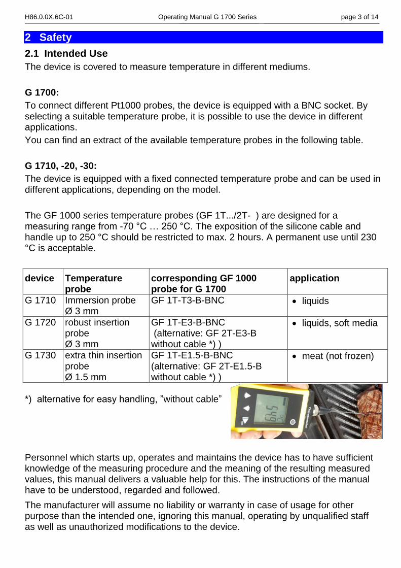
G 1730 extra thin insertion probe Ø 1.5 mm
GF 1T-E1.5-B-BNC (alternative: GF 2T-E1.5-B without cable *) )
meat (not frozen)
*) alternative for easy handling, ”without cable”
Personnel which starts up, operates and maintains the device has to have sufficient knowledge of the measuring procedure and the meaning of the resulting measured values, this manual delivers a valuable help for this. The instructions of the manual have to be understood, regarded and followed.
The manufacturer will assume no liability or warranty in case of usage for other purpose than the intended one, ignoring this manual, operating by unqualified staff as well as unauthorized modifications to the device.
H86.0.0X.6C-01 Operating Manual G 1700 Series page 4 of 14 _____________________________________________________ _____________________________________________________________________________
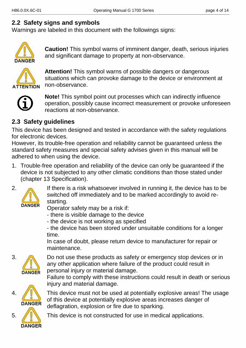
2.2 Safety signs and symbols Warnings are labeled in this document with the followings signs:
Caution! This symbol warns of imminent danger, death, serious injuries and significant damage to property at non-observance.
Attention! This symbol warns of possible dangers or dangerous situations which can provoke damage to the device or environment at non-observance.
Note! This symbol point out processes which can indirectly influence operation, possibly cause incorrect measurement or provoke unforeseen reactions at non-observance.
2.3 Safety guidelines
This device has been designed and tested in accordance with the safety regulations for electronic devices. However, its trouble-free operation and reliability cannot be guaranteed unless the standard safety measures and special safety advises given in this manual will be adhered to when using the device.
1. Trouble-free operation and reliability of the device can only be guaranteed if the device is not subjected to any other climatic conditions than those stated under (chapter 13 Specification).
2. If there is a risk whatsoever involved in running it, the device has to be switched off immediately and to be marked accordingly to avoid re-starting. Operator safety may be a risk if: - there is visible damage to the device - the device is not working as specified - the device has been stored under unsuitable conditions for a longer time. In case of doubt, please return device to manufacturer for repair or maintenance.
3. Do not use these products as safety or emergency stop devices or in any other application where failure of the product could result in personal injury or material damage. Failure to comply with these instructions could result in death or serious injury and material damage.
4. This device must not be used at potentially explosive areas! The usage of this device at potentially explosive areas increases danger of deflagration, explosion or fire due to sparking.
5. This device is not constructed for use in medical applications.
H86.0.0X.6C-01 Operating Manual G 1700 Series page 5 of 14 _____________________________________________________ _____________________________________________________________________________
6. Due to the pointed probe design there is a risk of stitch injury for devices with insertion probe.
7. Consider when measuring in food:
According to the regulation (EG) 1935/2004 the following parts of the equipment are laid-out for the permanent contact with food :
The stainless steel tube from the temperature probe of the measuring tip till approx. 1 cm before the probe handle
Probe handle, connector cable and the device housing are not construed for the permanent contact with food.
3 Product description
3.1 Scope of delivery
The scope of supply includes:
Device with 2 batteries type AA
Fixed connected temperature probe (not G 1700)
Operating Manual
Calibration protocol
3.2 Operating and Maintenance
1. Temperature measuring / probe connection:
For the models with fixed connected probes, the device is factory-adjusted to the temperature probe – here the highest system accuracy can be achieved. To optimize the accuracy, an offset and a slope correction can be executed at the G 1700 (take a look at chapter 8 Adjustment of temperature input).
By the devices with fixed connected temperature probes, it is not necessary.
2. Battery operation: If the battery has been used up and needs to be replaced, the empty frame of the battery symbol starts blinking. The device will, however, continue operating correctly for a certain time. The battery has been completely used up, if ´bAt´ is shown in the main display. Battery replacement: (see chapter 10 Replacing batteries).
The battery has to be removed, when storing device above 50°C.
We recommend taking out the batteries if device is not used for a longer period of time.
3. Treat device and probes carefully. Use only in accordance with above specification. (do not throw, hit against etc.). Protect plug and socket from soiling.
H86.0.0X.6C-01 Operating Manual G 1700 Series page 6 of 14 _____________________________________________________ _____________________________________________________________________________
4 Operation
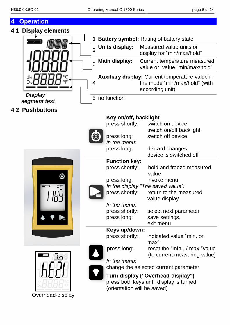
4.1 Display elements
Display segment test
1 Battery symbol: Rating of battery state
2 Units display: Measured value units or
display for “min/max/hold”
3 Main display: Current temperature measured
value or value ”min/max/hold”
4 Auxiliary display: Current temperature value in
the mode “min/max/hold” (with according unit)
5 no function
4.2 Pushbuttons
Overhead-display
Key on/off, backlight press shortly: switch on device
switch on/off backlight press long: switch off device In the menu: press long: discard changes,
device is switched off
Function key: press shortly: hold and freeze measured
value press long: invoke menu In the display “The saved value”: press shortly: return to the measured
value display In the menu: press shortly: select next parameter press long: save settings, exit menu
Keys up/down: press shortly: indicated value “min. or
max” press long: reset the “min-, / max-”value
(to current measuring value) In the menu: change the selected current parameter
Turn display (”Overhead-display“) press both keys until display is turned (orientation will be saved)
H86.0.0X.6C-01 Operating Manual G 1700 Series page 7 of 14 _____________________________________________________ _____________________________________________________________________________
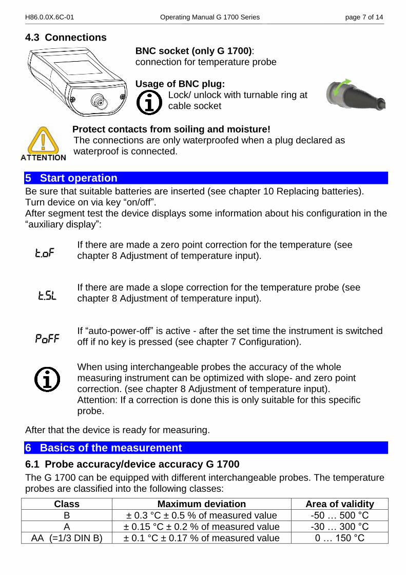
4.3 Connections
BNC socket (only G 1700): connection for temperature probe Usage of BNC plug:
Lock/ unlock with turnable ring at cable socket
Protect contacts from soiling and moisture! The connections are only waterproofed when a plug declared as waterproof is connected.
5 Start operation
Be sure that suitable batteries are inserted (see chapter 10 Replacing batteries). Turn device on via key “on/off”. After segment test the device displays some information about his configuration in the “auxiliary display”:
T.OF If there are made a zero point correction for the temperature (see chapter 8 Adjustment of temperature input).
T.SL If there are made a slope correction for the temperature probe (see chapter 8 Adjustment of temperature input).
POFF If “auto-power-off” is active - after the set time the instrument is switched off if no key is pressed (see chapter 7 Configuration).
When using interchangeable probes the accuracy of the whole measuring instrument can be optimized with slope- and zero point correction. (see chapter 8 Adjustment of temperature input). Attention: If a correction is done this is only suitable for this specific probe.
After that the device is ready for measuring.
6 Basics of the measurement
6.1 Probe accuracy/device accuracy G 1700
The G 1700 can be equipped with different interchangeable probes. The temperature probes are classified into the following classes:
Class Maximum deviation Area of validity
B ± 0.3 °C ± 0.5 % of measured value -50 … 500 °C
A ± 0.15 °C ± 0.2 % of measured value -30 … 300 °C
AA (=1/3 DIN B) ± 0.1 °C ± 0.17 % of measured value 0 … 150 °C
H86.0.0X.6C-01 Operating Manual G 1700 Series page 8 of 14 _____________________________________________________ _____________________________________________________________________________
To receive high exchange accuracy without necessity of additional adjustment we recommend the usage of temperature probes from the class “A” or “AA”.
6.2 Probe accuracy/device accuracy G 1700 / -20 / -30
The display unit and the probe of instruments with fixed mounted probes have been matched very accurate ex works, see chapter 13 Specification.
6.3 Possible errors
Immersion depth
For measurements in liquids the probe should be immersed sufficiently deep (depending on probe diameter, at least 20 mm with Ø 3 mm and 10 mm with Ø 1.5 mm) and subsequently stirred.
When measuring gases the probe should also emerge as deep as possible in the gas to be measured (e.g. when measuring in channels/pipes) and the gas should flow around the probe at sufficient flow.
Surface effects and bad heat transfer
For surface temperature measurements special surface probes are necessary. Surface quality, heat transfer and ambient temperature have an influence on the measurement result.
Cooling (evaporation)
For air temperature measurements, the probe should be dry, otherwise it can be possible that a too low temperature could be measured.
Response time
Before reading the measured value at the measuring process, it is necessary to wait a sufficient time (see chapter 13 Specification – Response time 90).
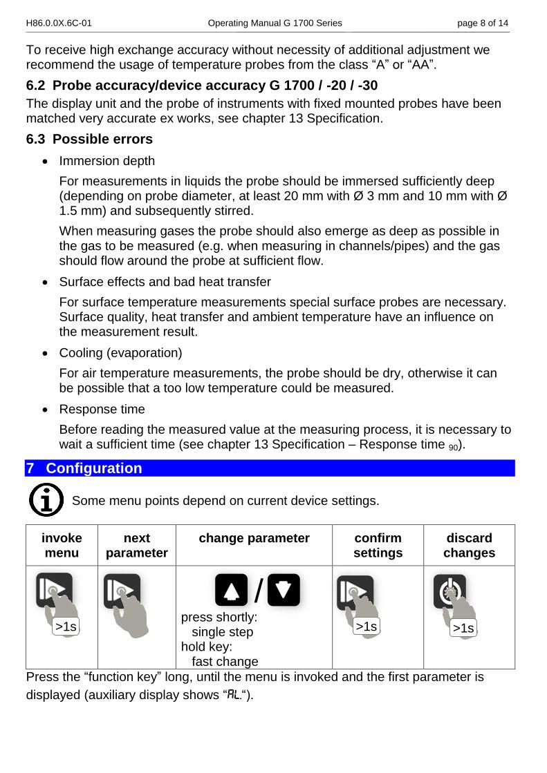
7 Configuration
Some menu points depend on current device settings.
invoke menu
next parameter
change parameter confirm settings
discard changes
/ press shortly: single step hold key: fast change
Press the “function key” long, until the menu is invoked and the first parameter is
displayed (auxiliary display shows “AL.“).
>1s >1s >1s
H86.0.0X.6C-01 Operating Manual G 1700 Series page 9 of 14 _____________________________________________________ _____________________________________________________________________________
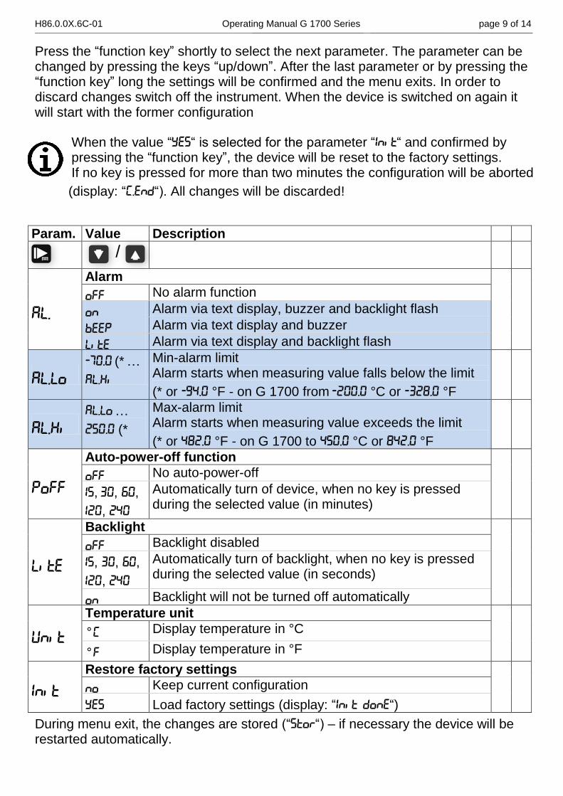
Press the “function key” shortly to select the next parameter. The parameter can be changed by pressing the keys “up/down”. After the last parameter or by pressing the “function key” long the settings will be confirmed and the menu exits. In order to discard changes switch off the instrument. When the device is switched on again it will start with the former configuration
When the value “YES“ is selected for the parameter “IN,T“ and confirmed by pressing the “function key”, the device will be reset to the factory settings. If no key is pressed for more than two minutes the configuration will be aborted
(display: “(.END“). All changes will be discarded!
Param. Value Description
/
AL.
Alarm
OFF No alarm function
ON Alarm via text display, buzzer and backlight flash
BEEP Alarm via text display and buzzer
L,TE Alarm via text display and backlight flash
AL.LO
-70.0 (* …
AL.K,
Min-alarm limit Alarm starts when measuring value falls below the limit
(* or -94.0 °F - on G 1700 from -200.0 °C or -328.0 °F
AL.K, AL.LO …
250.0 (*
Max-alarm limit Alarm starts when measuring value exceeds the limit
(* or 482.0 °F - on G 1700 to 450.0 °C or 842.0 °F
POFF
Auto-power-off function
OFF No auto-power-off
15, 30, 60,
120, 240
Automatically turn of device, when no key is pressed during the selected value (in minutes)
L,TE
Backlight
OFF Backlight disabled
15, 30, 60,
120, 240
Automatically turn of backlight, when no key is pressed during the selected value (in seconds)
ON Backlight will not be turned off automatically
UN,T
Temperature unit
°[ Display temperature in °C
°F Display temperature in °F
IN,T
Restore factory settings
NO Keep current configuration
YES Load factory settings (display: “IN,T DONE“)
During menu exit, the changes are stored (“STOR“) – if necessary the device will be restarted automatically.
H86.0.0X.6C-01 Operating Manual G 1700 Series page 10 of 14 _____________________________________________________ _____________________________________________________________________________
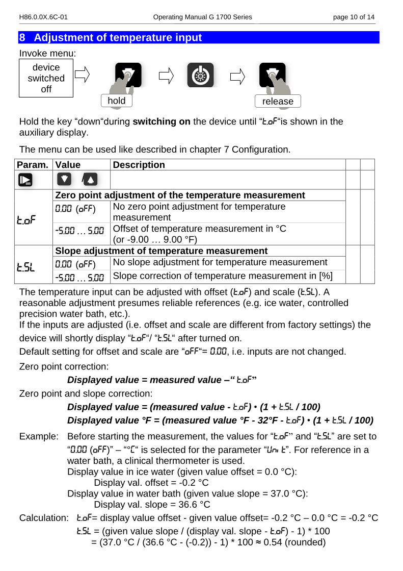
8 Adjustment of temperature input
Invoke menu:
Hold the key “down“during switching on the device until “T.OF“is shown in the auxiliary display.
The menu can be used like described in chapter 7 Configuration.
Param. Value Description
/
T.OF
Zero point adjustment of the temperature measurement
0.00 (OFF) No zero point adjustment for temperature measurement
-5.00 … 5.00 Offset of temperature measurement in °C (or -9.00 … 9.00 °F)
T.SL
Slope adjustment of temperature measurement
0.00 (OFF) No slope adjustment for temperature measurement
-5.00 … 5.00 Slope correction of temperature measurement in [%]
The temperature input can be adjusted with offset (T.OF) and scale (T.SL). A reasonable adjustment presumes reliable references (e.g. ice water, controlled precision water bath, etc.). If the inputs are adjusted (i.e. offset and scale are different from factory settings) the
device will shortly display “T.OF“/ “T.SL“ after turned on.
Default setting for offset and scale are “OFF“= 0.00, i.e. inputs are not changed.
Zero point correction:
Displayed value = measured value –“ T.OF”
Zero point and slope correction:
Displayed value = (measured value - T.OF) • (1 + T.SL / 100)
Displayed value °F = (measured value °F - 32°F - T.OF) • (1 + T.SL / 100)
Example: Before starting the measurement, the values for “T.OF” and “T.SL” are set to
“0.00 (OFF)” – “°[“ is selected for the parameter “UN,T”. For reference in a water bath, a clinical thermometer is used. Display value in ice water (given value offset = 0.0 °C): Display val. offset = -0.2 °C Display value in water bath (given value slope = 37.0 °C): Display val. slope = 36.6 °C
Calculation: T.OF= display value offset - given value offset= -0.2 °C – 0.0 °C = -0.2 °C
T.SL = (given value slope / (display val. slope - T.OF) - 1) * 100 = (37.0 °C / (36.6 °C - (-0.2)) - 1) * 100 ≈ 0.54 (rounded)
hold release
device switched
off
H86.0.0X.6C-01 Operating Manual G 1700 Series page 11 of 14 _____________________________________________________ _____________________________________________________________________________
9 Accuracy check / adjustment service
You can send the device to the manufacturer for adjustment and inspection. Calibration certificate - DKD certificate - official certifications: If the measuring instrument is supposed to receive a calibration certificate, it has to be sent to the manufacturer (declare test points, e. g. –20 °C; 0°C; 70°C). If the device is certificated together with a suitable sensor very high overall accuracies are possible. Basic settings can only be checked and – if necessary – corrected by the manufacturer. A calibration protocol is enclosed to the device ex works. This documents the precision reached by the production process.
10 Replacing batteries
Before changing batteries, please read the following instruction and follow it step by step. Not following the instruction may cause harm to the instrument or the protection against ingress of water and dust may be lost! Avoid unnecessary opening of the instrument!
Do not use different types or batteries with different state of charge. We recommend using new and high quality alkaline batteries.
The use of damaged or unsuitable batteries could lead to further heating, whereby the batteries can burst or in the worst case exploding.
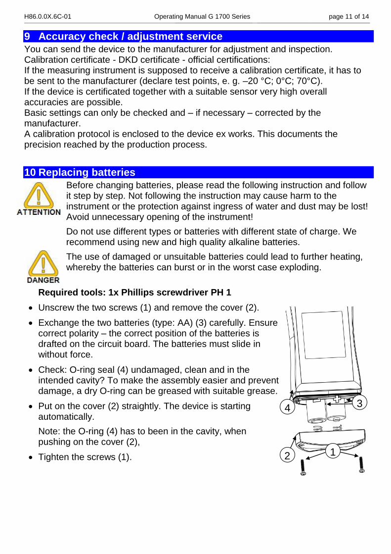
Required tools: 1x Phillips screwdriver PH 1
Unscrew the two screws (1) and remove the cover (2).
Exchange the two batteries (type: AA) (3) carefully. Ensure correct polarity – the correct position of the batteries is drafted on the circuit board. The batteries must slide in without force.
Check: O-ring seal (4) undamaged, clean and in the intended cavity? To make the assembly easier and prevent damage, a dry O-ring can be greased with suitable grease.
Put on the cover (2) straightly. The device is starting automatically.
Note: the O-ring (4) has to been in the cavity, when pushing on the cover (2),
Tighten the screws (1).
1 2
3 4
H86.0.0X.6C-01 Operating Manual G 1700 Series page 12 of 14 _____________________________________________________ _____________________________________________________________________________
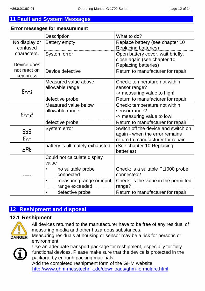
11 Fault and System Messages
Error messages for measurement
Description What to do?
No display or confused
characters,
Device does not react on key press
Battery empty Replace battery (see chapter 10 Replacing batteries)
System error Open battery cover, wait briefly, close again (see chapter 10 Replacing batteries)
Device defective Return to manufacturer for repair
ERR.1
Measured value above allowable range
Check: temperature not within sensor range? -> measuring value to high!
defective probe Return to manufacturer for repair
ERR.2
Measured value below allowable range
Check: temperature not within sensor range? -> measuring value to low!
defective probe Return to manufacturer for repair
SYS
ERR
System error Switch off the device and switch on again - when the error remains return to manufacturer for repair
BAT battery is ultimately exhausted (See chapter 10 Replacing
batteries)
----
Could not calculate display value
• no suitable probe connected
Check: is a suitable Pt1000 probe connected?
• measuring range or input range exceeded
Check: is the value in the permitted range?
• defective probe Return to manufacturer for repair
12 Reshipment and disposal
12.1 Reshipment
All devices returned to the manufacturer have to be free of any residual of measuring media and other hazardous substances. Measuring residuals at housing or sensor may be a risk for persons or environment
Use an adequate transport package for reshipment, especially for fully functional devices. Please make sure that the device is protected in the package by enough packing materials. Add the completed reshipment form of the GHM website http://www.ghm-messtechnik.de/downloads/ghm-formulare.html.
H86.0.0X.6C-01 Operating Manual G 1700 Series page 13 of 14 _____________________________________________________ _____________________________________________________________________________
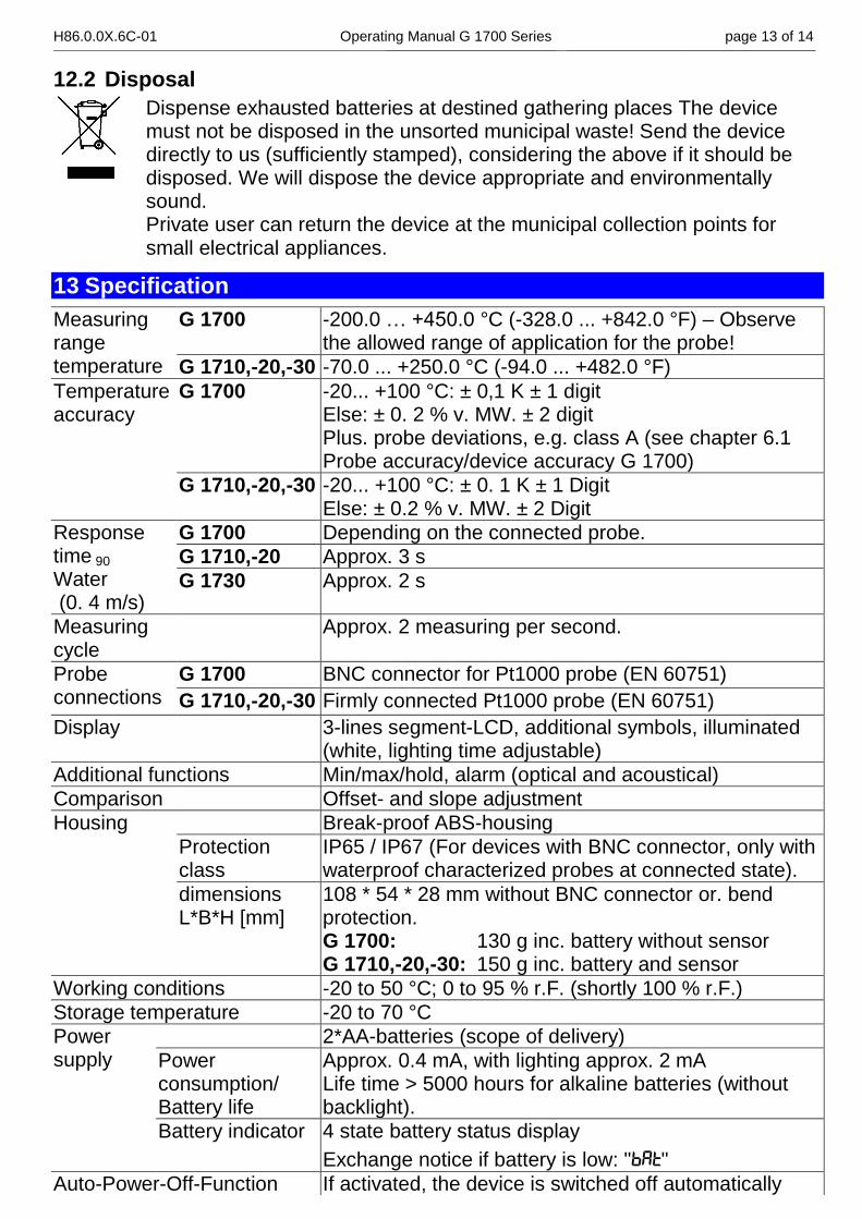
12.2 Disposal
Dispense exhausted batteries at destined gathering places The device must not be disposed in the unsorted municipal waste! Send the device directly to us (sufficiently stamped), considering the above if it should be disposed. We will dispose the device appropriate and environmentally sound. Private user can return the device at the municipal collection points for small electrical appliances.
13 Specification
Measuring range temperature
G 1700 -200.0 … +450.0 °C (-328.0 ... +842.0 °F) – Observe the allowed range of application for the probe!
G 1710,-20,-30 -70.0 ... +250.0 °C (-94.0 ... +482.0 °F)
Temperature accuracy
G 1700 -20... +100 °C: ± 0,1 K ± 1 digit Else: ± 0. 2 % v. MW. ± 2 digit Plus. probe deviations, e.g. class A (see chapter 6.1 Probe accuracy/device accuracy G 1700)
G 1710,-20,-30 -20... +100 °C: ± 0. 1 K ± 1 Digit Else: ± 0.2 % v. MW. ± 2 Digit
Response time 90
Water (0. 4 m/s)
G 1700 Depending on the connected probe.
G 1710,-20 Approx. 3 s
G 1730 Approx. 2 s
Measuring cycle
Approx. 2 measuring per second.
Probe connections
G 1700 BNC connector for Pt1000 probe (EN 60751)
G 1710,-20,-30 Firmly connected Pt1000 probe (EN 60751)
Display 3-lines segment-LCD, additional symbols, illuminated (white, lighting time adjustable)
Additional functions Min/max/hold, alarm (optical and acoustical)
Comparison Offset- and slope adjustment
Housing Break-proof ABS-housing
Protection class
IP65 / IP67 (For devices with BNC connector, only with waterproof characterized probes at connected state).
dimensions L*B*H [mm]
108 * 54 * 28 mm without BNC connector or. bend protection. G 1700: 130 g inc. battery without sensor G 1710,-20,-30: 150 g inc. battery and sensor
Working conditions -20 to 50 °C; 0 to 95 % r.F. (shortly 100 % r.F.)
Storage temperature -20 to 70 °C
Power supply
2*AA-batteries (scope of delivery)
Power consumption/ Battery life
Approx. 0.4 mA, with lighting approx. 2 mA Life time > 5000 hours for alkaline batteries (without backlight).
Battery indicator 4 state battery status display
Exchange notice if battery is low: "BAT"
Auto-Power-Off-Function If activated, the device is switched off automatically
H86.0.0X.6C-01 Operating Manual G 1700 Series page 14 of 14 _____________________________________________________ _____________________________________________________________________________
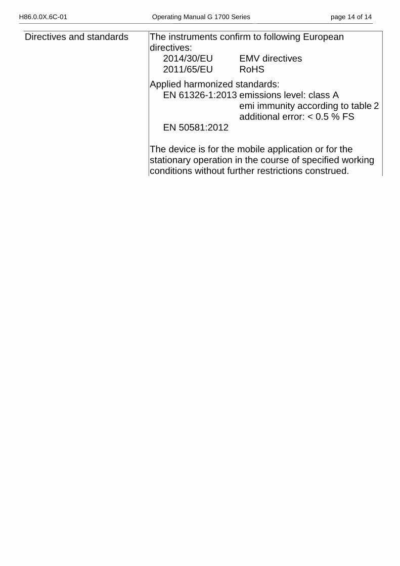
Directives and standards The instruments confirm to following European directives: 2014/30/EU EMV directives 2011/65/EU RoHS
Applied harmonized standards: EN 61326-1:2013 emissions level: class A emi immunity according to table 2 additional error: < 0.5 % FS EN 50581:2012 The device is for the mobile application or for the stationary operation in the course of specified working conditions without further restrictions construed.


