
GeneralTechnical
The Fitting Authority
Burst Test Leak Test
Hardness Test
Impulse Test Vibration Test

U2 Parker Hannifin CorporationTube Fittings DivisionColumbus, Ohiowww.parker.com/tfd
4300 Catalog General Technical
How To Order ............................................................................................... U3
Standard Nomenclature (Seal-Lok, Triple-Lok, Ferulok, Intru-Lok, JIS and K4) .......................................................................................... U3
Hydraulic Flange Nomenclature ................................................................ U4
EO/EO-2 Nomenclature ............................................................................. U5
Connectors for World Class Products ............................................... U6
Conformance Standards ......................................................................... U9
Compatibility ..............................................................................................U10
Media Compatability .................................................................................U10
Material Compatibility ...............................................................................U10
Corrosion of Base Metals in Contact ........................................................U12
O-Ring / Seal Material Selection...............................................................U13
Tube Selection ............................................................................................U14
Tube and Fitting Material Compatibility.....................................................U14
Determining Tube Size .............................................................................U15
Recommended Flow Diameters ...............................................................U17
Inch Tube Pressure Ratings .....................................................................U19
Metric Tube Pressure Ratings ..................................................................U21
Tube Fitting Pressure Drop ...................................................................U22
Fitting and Adapter Pressure Ratings ..............................................U24
Port Details ..................................................................................................U25
ISO 6149-1 (Metric ORB) .........................................................................U25
SAE J1926-1 (SAE-ORB) .........................................................................U26
SAE Straight Thread Connector Use in MS33649 ....................................U27
ISO 6162 / SAE J518 (Code 61/62) ..........................................................U28
ISO 1179-1 (BSPP) ..................................................................................U29
ISO 9974-1 ...............................................................................................U30
NPT / NPTF ..............................................................................................U31
Port End Summary ...................................................................................U32
Tube-to-Port Pairings ...............................................................................U32

4300 Catalog General Technical
U3 Parker Hannifin CorporationTube Fittings DivisionColumbus, Ohiowww.parker.com/tfd
How to Order Seal-Lok, Triple-Lok, Ferulok, Intru-Lok, JIS and K4
TFD Standard Nomenclature Construction
1 to 4 setsof numbersfrom Box 1
Letter codefrom Box 2
Number/Lettercode from
Box 3
Number/Lettercode from
Box 4
Letter codefrom Box 5
Example: Steel Seal-Lok Adjustable Elbow Connector –3/8" O.D. (-6) Tube to 7/16-20 UNF (-4) ORB =
6-4 C5L-S(See the shading in the boxes below for the construction of this example)
Box 1 Box 2 Box 3 Box 4 — Box 5Size Shape or Style Sub-Style Type Material
Dash Size
Tube O.D.
Dash Size
SAE Straight Thread
Dash Size
NPTF Pipe Thread
-2 1/8 -2 5/16-24 -2 1/8-3 3/16 -3 3/8-24 -2 1/8-4 1/4 -4 7/16-20 -2 1/8-5 5/16 -5 1/2-20 -2 1/8-6 3/8 -6 9/16-18 -4 1/4-8 1/2 -8 3/4-16 -6 3/8-10 5/8 -10 7/8-14 -8 1/2-12 3/4 -12 1 1/16-12 -12 3/4-14 7/8 -14 1 3/16-12 -12 3/4-16 1 -16 1 5/16-12 -16 1-20 1 1/4 -20 1 5/8-12 -20 1 1/4-24 1 1/2 -24 1 7/8-12 -24 1 1/2-32 2 -32 2 1/2-12 -32 2
Tube End Port End Port EndBox 1 – Paired Tube and Port End Size Code Table
B NutF* Male Connector
FF*Long Male Connector or Pipe Nipple
FFF*Extra Long Connector or Long Pipe Nipple
FN CapG* Female ConnectorH UnionHH Long Union
HPN* Plug, Straight Thread, Hollow Hex
LH Large Hex Union
PN*Plug, Straight Thread, Hex Head
T Sleeve or FerruleTP Sleeve, ParflangeTR Tube ReducerT22 MountieW Bulkhead UnionWF Bulkhead MaleWG Bulkhead Female
WLNBulkhead Locknut for Triple-Lok, Ferulok and Intru-Lok
WLNLBulkhead Locknut for Seal-Lok
C* Male Elbow ConnectorCC* Long Male Elbow
CCC* Extra Long Male Elbow
D Female ElbowE Union ElbowWE Bulkhead Union Elbow
N Union ElbowV* Male Elbow ConnectorWN Bulhead Union Elbow
J Union TeeM Female Run TeeO Female Branch TeeR* Male Run TeeS* Male Branch TeeWJ Bulkhead Branch TeeWJJ Bulhead Run Tee
K Union Cross
Box 2 – Shape or StyleStraights
Cross
Tees
45° Elbows
90° Elbows
3 BSPT Port End4 BSPP Port End, O-ring & RR5 SAE Straight Thread Port End8 Metric Port End, O-ring & RR9 SAE-ORB with Metal Seal42 BSPP Port End, "ED" Seal47 BSPP O-ring Port, B235182 Metric Port End, "ED" Seal87 ISO 6149 Port End
J4 (e) Banjo Connection, BSPP, Soft SealJ8 (e) Banjo Connection, Metric, Soft Seal
6 Female Swivel
63 BSPT Port, Swivel Connector64 BSPP Port, Swivel Connector642 BSPP, "ED" Seal, Swivel Connector65 SAE-ORB, Swivel Connector68 Metric Port, Swivel Connector682 Metric Port, Swivel Connector687 ISO 6149, Swivel Connector
S – for Seal-LokL – for all other types
Box 3 – Sub-Style Modifiers(Connectors, Swivels and Plugs)
Connectors (a)
Swivel Unions (b)
Swivel Connectors (c)
Notes
Straight Thread Plugs (d)4, 5, 8, 9 and 87 as in Connectors above.
a. Modifiers for Connectors as noted with asterisk in Box 2. Series L (light) and S (heavy), for male connectors is determined by type of fitting.
c. Modifiers for F only in Box 2.
d. Modifiers for P only in PN and HPN in Box 2.
e. Applies to 90° elbows and tees only.
b. Modifier for C, V, R, S, H, E and J in Box 2.
I Intru-LokK4 60° Cone BSPPL Seal-LokP4 JIS 60° ConeT4 JIS 30° FlareU FerulokX Triple-Lok
Box 4 – Fitting TypeB Brass
CUNICupro-Nickel (ex. CUNI 70/30)
D Dural (Aluminum)M Monel
SSteel w/zinc plating
SSStainless Steel, 316/316L passivated
Box 5 – Material Code
U4 Parker Hannifin CorporationTube Fittings DivisionColumbus, Ohiowww.parker.com/tfd
4300 Catalog General Technical
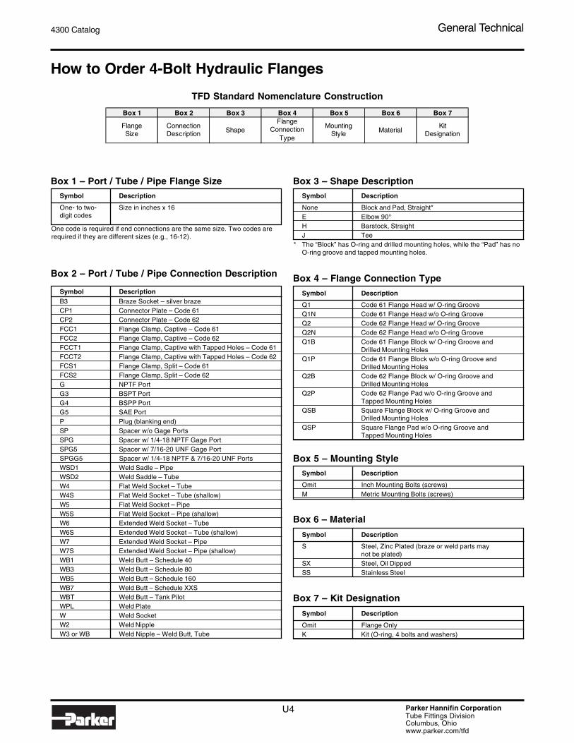
How to Order 4-Bolt Hydraulic Flanges
Symbol Description
One- to two- Size in inches x 16digit codes
One code is required if end connections are the same size. Two codes arerequired if they are different sizes (e.g., 16-12).
Symbol DescriptionB3 Braze Socket – silver brazeCP1 Connector Plate – Code 61CP2 Connector Plate – Code 62FCC1 Flange Clamp, Captive – Code 61FCC2 Flange Clamp, Captive – Code 62FCCT1 Flange Clamp, Captive with Tapped Holes – Code 61FCCT2 Flange Clamp, Captive with Tapped Holes – Code 62FCS1 Flange Clamp, Split – Code 61FCS2 Flange Clamp, Split – Code 62G NPTF PortG3 BSPT PortG4 BSPP PortG5 SAE PortP Plug (blanking end)SP Spacer w/o Gage PortsSPG Spacer w/ 1/4-18 NPTF Gage PortSPG5 Spacer w/ 7/16-20 UNF Gage PortSPGG5 Spacer w/ 1/4-18 NPTF & 7/16-20 UNF PortsWSD1 Weld Sadle – PipeWSD2 Weld Saddle – TubeW4 Flat Weld Socket – TubeW4S Flat Weld Socket – Tube (shallow)W5 Flat Weld Socket – PipeW5S Flat Weld Socket – Pipe (shallow)W6 Extended Weld Socket – TubeW6S Extended Weld Socket – Tube (shallow)W7 Extended Weld Socket – PipeW7S Extended Weld Socket – Pipe (shallow)WB1 Weld Butt – Schedule 40WB3 Weld Butt – Schedule 80WB5 Weld Butt – Schedule 160WB7 Weld Butt – Schedule XXSWBT Weld Butt – Tank PilotWPL Weld PlateW Weld SocketW2 Weld NippleW3 or WB Weld Nipple – Weld Butt, Tube
Symbol Description
None Block and Pad, Straight*E Elbow 90°H Barstock, StraightJ Tee
* The “Block” has O-ring and drilled mounting holes, while the “Pad” has noO-ring groove and tapped mounting holes.
Symbol Description
Q1 Code 61 Flange Head w/ O-ring GrooveQ1N Code 61 Flange Head w/o O-ring GrooveQ2 Code 62 Flange Head w/ O-ring GrooveQ2N Code 62 Flange Head w/o O-ring GrooveQ1B Code 61 Flange Block w/ O-ring Groove and
Drilled Mounting HolesQ1P Code 61 Flange Block w/o O-ring Groove and
Drilled Mounting HolesQ2B Code 62 Flange Block w/ O-ring Groove and
Drilled Mounting HolesQ2P Code 62 Flange Pad w/o O-ring Groove and
Tapped Mounting HolesQSB Square Flange Block w/ O-ring Groove and
Drilled Mounting HolesQSP Square Flange Pad w/o O-ring Groove and
Tapped Mounting Holes
Symbol Description
Omit Inch Mounting Bolts (screws)M Metric Mounting Bolts (screws)
Symbol Description
S Steel, Zinc Plated (braze or weld parts maynot be plated)
SX Steel, Oil DippedSS Stainless Steel
Symbol Description
Omit Flange OnlyK Kit (O-ring, 4 bolts and washers)
Box 1 – Port / Tube / Pipe Flange Size
Box 2 – Port / Tube / Pipe Connection Description
Box 3 – Shape Description
Box 4 – Flange Connection Type
Box 5 – Mounting Style
Box 6 – Material
Box 7 – Kit Designation
TFD Standard Nomenclature Construction
Box 1 Box 2 Box 3 Box 4 Box 5 Box 6 Box 7
Flange Size
Connection Description Shape
Flange Connection
Type
Mounting Style Material
Kit Designation

4300 Catalog General Technical
U5 Parker Hannifin CorporationTube Fittings DivisionColumbus, Ohiowww.parker.com/tfd
How to Order EO and EO-2 Fittings and Accessories
TFD Standard Nomenclature Construction
Box 1 Box 2 Box 3 Box 4 Box 5 Box 6 Box 7 Box 8 Box 9
Shape / StyleTube Size
(mm)EO-2
DesignatorPressure
SeriesPort Size / Designator
Port Sealing Method Modifier Modifier 1 Material Modifier 2
Straights TeesAS Weld Connector EL Swivel Nut RunAS__/ Weld Flange ET Swivel Nut BranchBFG Square Flange Connector GMA1/ Union w/ Test Point, PinDA Distance Adapter GMA3/ Union w/ Test Point, M16x2DG101/ Rotary Union LEE Adjustable RunDG102/ Rotary Connector T UnionDG107/ Rotary Bulkhead Union TEE Adjustable BranchDVGE Plain Bearing Rotary TH High Pressure BanjoEGE Swivel Nut Connector TR Reducer UnionEGEO ISO 6149 Swivel Nut Connector WV Alternating ValveESV Weld Bulkhead Union CrossG Union K UnionGAI Female Connector AccessoriesGE Male Connector D Cutting RingGEO ISO 6149 Connector DKA Metal Seal RingGFS__/ Flange Connector DKI Pressure Gage SealGR Reducer Union DOZ EO-2 Seal RingGZ Swivel Union DPR Progressive RingGZR Reducer Swivel Union E InsertMAV Gage Connector ED EOlastic SealMAVE Swivel Nut Gage Connector FM EO-2 Functional NutRED Tube End Reducer GM Bulkhead LocknutSKA Weld Adapter KD Plastic SealSV Bulkhead Union KDS Elastomeric SealVKA1/ Test Point Connector, Pin M Tube NutVKA3/ Test Point Connector, M16x2 OR O-ring90° Elbows PSR Progressive Ring (new)BFW Square Flange Connector R TubeDG103/ Rotary Union ROV PlugDG104/ Rotary Connector VH InsertDG108/ Rotary Bulkhead Union VKA CapDVWE Plain Bearing Rotary VSTI Hollow Hex PlugEW Swivel Nut ValvesSWVE Banjo RHD Union CheckW Union RHV Connector CheckWAS Weld Connector RHZ Connector CheckWE Male Connector RHDI Female CheckWEE Adjustable RVP Cartridge CheckWFS__/ Flange Connector DV Low Pressure Shut OffWH High Pressure Banjo LD Medium Pressure Shut OffWSV Bulkhead Union VDHA High Pressure Shut OffDouble 90° Elbows VDHB High Pressure Shut OffDG105/ Rotary Union KH 2-way Ball ValveDG106/ Rotary Connector KH3/2- 3-way Ball Valve45° Elbows WV Alternating Union TeeEV Swivel NutVEE Adjustable
Box 1 - Shape/Style Code Box 2 – Tube Size
(mm)040506081012141516182022252830353842
Z EO-2 Assy.
Box 3 – EO-2
Designator
LL Very lightL LightS Heavy
Box 4 – Pressure
Series
M_ Metric Parallel
M_X_Metric Parallel (Jump Size)
M_X_keg Metric Taper
1/8NPT NPT Thread1/4NPT NPT Thread3/8NPT NPT Thread1/2NPT NPT Thread3/4NPT NPT Thread1NPT NPT Thread1 1/4NPT NPT Thread1 1/2NPT NPT Thread
7/16UNF Inch Parallel Thread9/16UNF Inch Parallel Thread3/4UNF Inch Parallel Thread3/4UNF Inch Parallel Thread7/8UNF Inch Parallel Thread
11/16UN Inch Parallel Thread15/16UN Inch Parallel Thread1 5/8UN Inch Parallel Thread
1 7/8UN
R_ BSPPR_/_keg BSPT
BSPP/BSPT
SAE-ORB
Box 5 – Port Size / Designator (optional)
Metric
NPT – Inch
ED EOlastic SealOR ISO 6149 O-ringKDS Banjo Seal-Ring
Box 6 – Port Sealing Method Modifier
(optional)
OMD Without Nut and Sleeve
VITFPM (omitted for Stainless)
NBRNitrile Seals (omitted for Steel and Brass)
_ _ BSpecial Cracking Pressure (check valve)
Box 7 – Modifier 1 (optional)
A3C Steel, Zinc Yellow PlatedA3K Steel, Zinc Clear PlatedMS Brass71 Stainless SteelVZ Zinc Plated (tube only)
Box 8 – Material
X UnassembledBox 9 – Modifier 2 (optional)
U6 Parker Hannifin CorporationTube Fittings DivisionColumbus, Ohiowww.parker.com/tfd
4300 Catalog General Technical
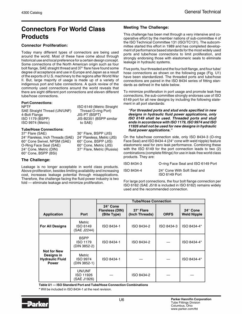
Connectors For World ClassProductsConnector Proliferation:
Today many different types of connectors are being usedaround the world. Most of these have come about throughhistorical use and local preference for a certain design concept.Some connections of the North American origin such as fourbolt flange, SAE straight thread and 37° flare have found somedegree of acceptance and use in Europe and Japan as a resultof the exports of U.S. machinery to the regions after World WarII. But, large majority of usage is made up of a variety ofindigenous port and tube connections. A quick review of thecommonly used connections around the world reveals thatthere are eight different port connections and eleven differenttube/hose connections.
Port Connections:NPTF ISO 6149 (Metric StraightSAE Straight Thread (UN/UNF) Thread O-ring Port)4-Bolt Flange JIS-PT (BSPT)ISO 1179 (BSPP) JIS-B2351 (BSPP similarISO 9974 (Metric) to SAE)
Tube/Hose Connections:37° Flare (SAE) 30° Flare, BSPP (JIS)24° Flareless, Inch Threads (SAE) 24° Flareless, Metric (JIS)60° Cone Swivel, NPSM (SAE) 60° Cone, BSPP (JIS)O-Ring Face Seal (SAE) 60° Cone, Metric (JIS)24° Cone, Metric (DIN) 37° Flare, Metric (Russia)60° Cone, BSPP (BSi)
The Challenge:
Leakage is no longer acceptable in world class products.Above proliferation, besides limiting availability and increasingcost, increases leakage potential through misapplications.Therefore, the challenge facing the fluid power industry is twofold — eliminate leakage and minimize proliferation.
Meeting The Challenge:
This challenge has been met through a very intensive and co-operative effort by the member nations of sub-committee 4 ofthe ISO Technical Committee 131 (ISO/TC131). The subcom-mittee started this effort in 1989 and has completed develop-ment of performance based standards for the most widely usedports and tube/hose connections to limit proliferation, andstrongly endorsing those with elastomeric seals to eliminateleakage in hydraulic systems.
Five ports, four threaded and the four bolt flange, and four tube/hose connections as shown on the following page (Fig. U1)have been standardized. The threaded ports and tube/hoseconnections are paired in the ISO 8434 series of fitting stan-dards as defined in the table below.
To minimize proliferation in port usage and promote leak freeconnections, the sub-committee strongly endorses use of ISO6149 port for all new designs by including the following state-ment in all port standards:
“For threaded ports and stud ends specified in newdesigns in hydraulic fluid power applications, onlyISO 6149 shall be used. Threaded ports and studends in accordance with ISO 1179, ISO 9974 and ISO11926 shall not be used for new designs in hydraulicfluid power applications.”
On the tube/hose connection side, only ISO 8434-3 (O-ringFace Seal) and ISO 8434-4 (24° cone with weld nipple) featureelastomeric seal for zero leak performance. Combining thesewith the ISO 6149 for the port connection leads to two (2)combinations (complete fittings) for use in leak-free world classproducts. They are:
ISO 8434-3 O-ring Face Seal and ISO 6149 Port
ISO 8434-4 24° Cone With Soft Seal andISO 6149 Port
For large port connections, the four bolt flange connection perISO 6162 (SAE J518 is included in ISO 6162) remains widelyused and the recommended connection.
Table U1 — ISO Standard Port and Tube/Hose Connection Combinations* Will be included in ISO 8434-1 at the next revision.
Tube/Hose Connection24° Cone
Flareless (DIN) 37° Flare 24° ConeApplication Port (Bite Type) (Inch Threads) ORFS Weld Nipple
MetricFor All Designs ISO 6149 ISO 8434-1 ISO 8434-2 ISO 8434-3 ISO 8434-4*
(SAE J2244)
BSPPISO 1179 ISO 8434-1 ISO 8434-2 — ISO 8434-4*
(DIN 3852-2)Not for NewDesigns in Metric
Hydraulic Fluid ISO 9974 ISO 8434-1 — — ISO 8434-4*Power (DIN 3852-1)
UN/UNFISO 11926 — ISO 8434-2 — —
(SAE J1926)
4300 Catalog General Technical
U7 Parker Hannifin CorporationTube Fittings DivisionColumbus, Ohiowww.parker.com/tfd
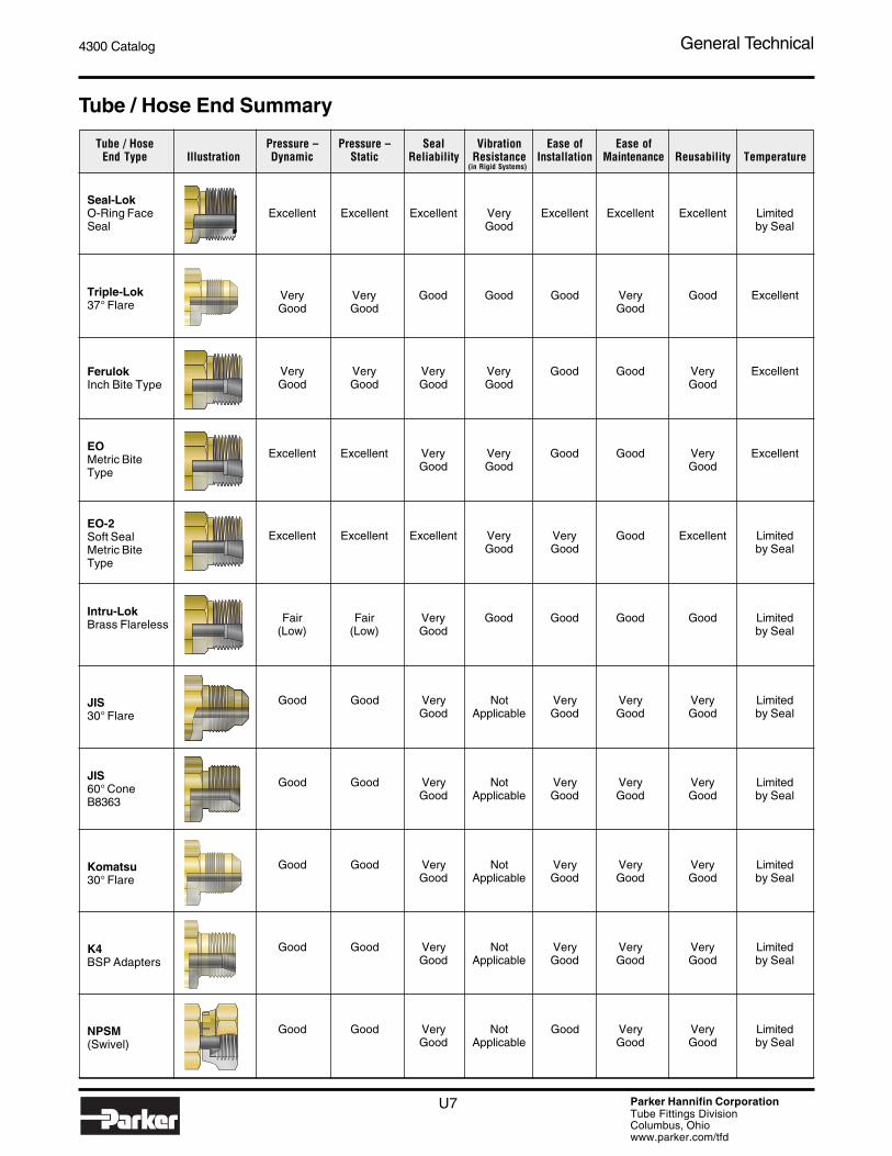
Tube / Hose End Summary
Tube / Hose Pressure – Pressure – Seal Vibration Ease of Ease ofEnd Type Illustration Dynamic Static Reliability Resistance Installation Maintenance Reusability Temperature
Very Very Good Good Good Very Good ExcellentGood Good Good
Very Very Very Very Good Good Very ExcellentGood Good Good Good Good
Excellent Excellent Very Very Good Good Very ExcellentGood Good Good
Excellent Excellent Excellent Very Very Good Excellent LimitedGood Good by Seal
Fair Fair Very Good Good Good Good Limited(Low) (Low) Good by Seal
Good Good Very Not Very Very Very LimitedGood Applicable Good Good Good by Seal
Good Good Very Not Very Very Very LimitedGood Applicable Good Good Good by Seal
Good Good Very Not Very Very Very LimitedGood Applicable Good Good Good by Seal
Good Good Very Not Very Very Very LimitedGood Applicable Good Good Good by Seal
Good Good Very Not Good Very Very LimitedGood Applicable Good Good by Seal
Excellent Excellent Excellent Very Excellent Excellent Excellent LimitedGood by Seal
K4BSP Adapters
Komatsu30° Flare
JIS60° ConeB8363
JIS30° Flare
Intru-LokBrass Flareless
EO-2Soft SealMetric BiteType
EOMetric BiteType
FerulokInch Bite Type
Triple-Lok37° Flare
Seal-LokO-Ring FaceSeal
NPSM(Swivel)
(in Rigid Systems)
U8 Parker Hannifin CorporationTube Fittings DivisionColumbus, Ohiowww.parker.com/tfd
4300 Catalog General Technical
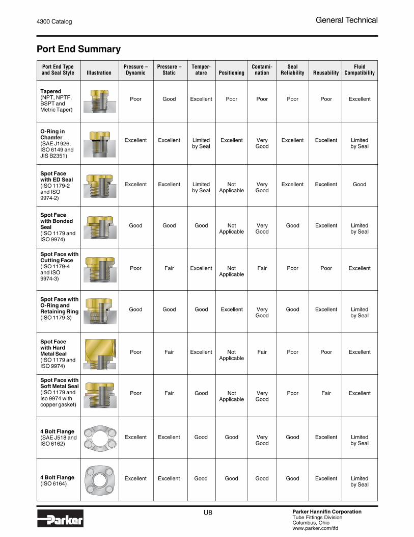
Port End Summary
Port End Type Pressure – Pressure – Temper- Contami- Seal Fluidand Seal Style Illustration Dynamic Static ature Positioning nation Reliability Reusability Compatibility
Tapered(NPT, NPTF,BSPT andMetric Taper)
O-Ring inChamfer(SAE J1926,ISO 6149 andJIS B2351)
Spot Facewith ED Seal(ISO 1179-2and ISO9974-2)
Spot Facewith BondedSeal(ISO 1179 andISO 9974)
Spot Face withCutting Face(ISO 1179-4and ISO9974-3)
Spot Face withO-Ring andRetaining Ring(ISO 1179-3)
Spot Facewith HardMetal Seal(ISO 1179 andISO 9974)
Spot Face withSoft Metal Seal(ISO 1179 andIso 9974 withcopper gasket)
4 Bolt Flange(SAE J518 andISO 6162)
4 Bolt Flange(ISO 6164)
Poor Good Excellent Poor Poor Poor Poor Excellent
Excellent Excellent Limited Excellent Very Excellent Excellent Limitedby Seal Good by Seal
Excellent Excellent Limited Not Very Excellent Excellent Goodby Seal Applicable Good
Good Good Good Not Very Good Excellent LimitedApplicable Good by Seal
Poor Fair Excellent Not Fair Poor Poor ExcellentApplicable
Good Good Good Excellent Very Good Excellent LimitedGood by Seal
Poor Fair Excellent Not Fair Poor Poor ExcellentApplicable
Poor Fair Good Not Very Poor Fair ExcellentApplicable Good
Excellent Excellent Good Good Very Good Excellent LimitedGood by Seal
Excellent Excellent Good Good Good Good Excellent Limitedby Seal
4300 Catalog General Technical
U9 Parker Hannifin CorporationTube Fittings DivisionColumbus, Ohiowww.parker.com/tfd
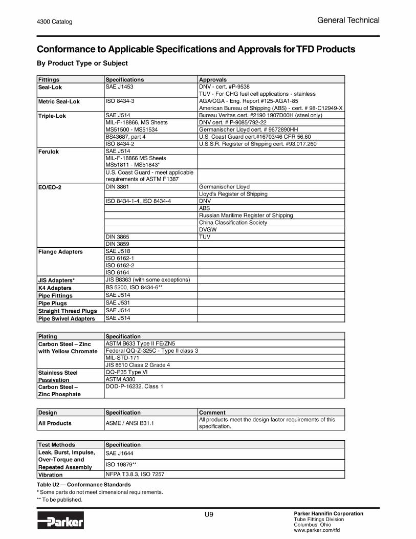
Conformance to Applicable Specifications and Approvals for TFD ProductsBy Product Type or Subject
Table U2 — Conformance Standards* Some parts do not meet dimensional requirements.** To be published.
Fittings Specifications ApprovalsDNV - cert. #P-9538 TUV - For CHG fuel cell applications - stainlessAGA/CGA - Eng. Report #125-AGA1-85American Bureau of Shipping (ABS) - cert. # 98-C12949-X
SAE J514 Bureau Veritas cert. #2190 1907D00H (steel only)MIL-F-18866, MS Sheets DNV cert. # P-9085/792-22MS51500 - MS51534 Germanischer Lloyd cert. # 9672890HHBS43687, part 4 U.S. Coast Guard cert.#16703/46 CFR 56.60ISO 8434-2 U.S.S.R. Register of Shipping cert. #93.017.260SAE J514MIL-F-18866 MS SheetsMS51811 - MS51843*U.S. Coast Guard - meet applicable requirements of ASTM F1387DIN 3861 Germanischer Lloyd
Lloyd's Register of ShippingISO 8434-1-4, ISO 8434-4 DNV
ABSRussian Maritime Register of ShippingChina Classification SocietyDVGW
DIN 3865 TUVDIN 3859SAE J518ISO 6162-1ISO 6162-2ISO 6164
JIS Adapters* JIS B8363 (with some exceptions)
K4 Adapters BS 5200, ISO 8434-6**
Pipe Fittings SAE J514
Pipe Plugs SAE J531
Straight Thread Plugs SAE J514
Pipe Swivel Adapters SAE J514
Plating
Carbon Steel – Zinc Phosphate
Design Specification Comment
All Products ASME / ANSI B31.1All products meet the design factor requirements of this specification.
Test Methods
Vibration
Specification
SAE J1644
NFPA T3.8.3, ISO 7257
ISO 19879**
SpecificationASTM B633 Type II FE/ZN5Federal QQ-Z-325C - Type II class 3MIL-STD-171JIS 8610 Class 2 Grade 4
Carbon Steel – Zinc with Yellow Chromate
Stainless Steel Passivation
Leak, Burst, Impulse, Over-Torque and Repeated Assembly
Triple-Lok
Ferulok
EO/EO-2
Flange Adapters
DOD-P-16232, Class 1
QQ-P35 Type VIASTM A380
Seal-Lok SAE J1453
Metric Seal-Lok ISO 8434-3

U10 Parker Hannifin CorporationTube Fittings DivisionColumbus, Ohiowww.parker.com/tfd
4300 Catalog General Technical
Choosing the TubeMaterial and TypeSelection of tube material depends on the fluid, corrosive natureof the service environment, the operating temperature range andthe maximum operating pressure. The tube O.D. and wall thick-ness selection depends on these four parameters.
A simple method of selecting the proper tube type and material isdescribed below.
Table U7 lists several common tube types with their recom-mended operating temperature ranges, general application,and fitting compatibility. Based on the fluid system parametersand media, select the appropriate tube type and material.
If media and/or service environment is different from the com-monly used ones listed in the general application column,please consult the Fluid Compatibility chart on the following pageor contact the Tube Fittings Division.
For selecting proper tube O.D. and wall thickness use theprocedure given on page U15.
Caution: When working with highly corrosive media,always consult the Tube Fittings Division.
Fluid CompatibilityThe fluid compatibility chart on the following page is intended asa guide only and is not to be considered as a sole selectioncriteria to use Parker Tube Fittings in a specific application orwith a specific fluid. Other factors that must be consideredinclude, but are not limited to: Fluid temperature, ambienttemperature, system pressure (both operating and peak) andapplicable standards or regulations. For media not listed, pleasecontact your Parker representative or the Tube Fittings Divi-sion.
Protective Coatings on SteelProtective coatings such as electroplated zinc and cadmium1)
and zinc phosphate are usually applied to steel fittings forextending their useful service life in corrosive environments.Cadmium and zinc corrode sacrificially, protecting the steelsubstrate from normal atmospheric rusting due to the commonpresence of oxygen, moisture and acidic gases. They are,however, rapidly attacked by many fluids including those con-taining acidic hydrogen and reactive fluorine, chlorine, bro-mine, iodine, and nitrogen. Zinc plating will further be attackedby strong bases or water with pH > 12. Zinc reacts with glycolbased fire resistant fluids and forms a gelatinous com-pound that can plug up filters and be harmful otherwise, ina system with many zinc plated tube and hose fittings. Steelfittings with zinc phosphate coating or stainless steel fittings,along with brass fittings in low pressure applications, are viableoptions.
The other option is to run the fluid through the system, withoutcomponents with moving parts in it, with an auxiliary powersource, to generate and flush the gelatinous compound. Thenre-connect all components, change filters and charge thesystem with new fluid.
Zinc phosphate coatings protect steel by covering its surfaceand will retard rusting as long as the inhibiting barrier is notbroken.
Caution: Where low toxicity and low corrosion arerequired, as in food or beverage applications, steelcoated with any form of zinc or other protective coat-ings is not recommended.
Notes:1) Cadmium is not allowed by SAE and ISO stardards for
general industrial and commercial use. Some militaryapplications still require cadmium plating. Theserequirements are met with special (non-standard)processing at extra cost.
4300 Catalog General Technical
U11 Parker Hannifin CorporationTube Fittings DivisionColumbus, Ohiowww.parker.com/tfd
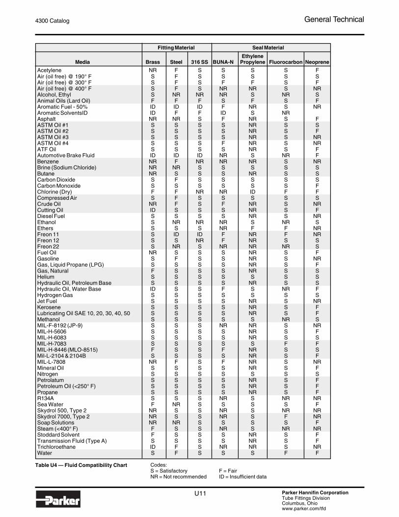
Table U4 — Fluid Compatibility Chart
Fitting Material Seal Material
EthyleneMedia Brass Steel 316 SS BUNA-N Propylene Fluorocarbon Neoprene
Acetylene NR F S S S S FAir (oil free) @ 190° F S F S S S S SAir (oil free) @ 300° F S F S F F S FAir (oil free) @ 400° F S F S NR NR S NRAlcohol, Ethyl S NR NR NR S NR SAnimal Oils (Lard Oil) F F F S F S FAromatic Fuel - 50% ID ID ID F NR S NRAromatic SolventsID ID F F ID S NRAsphalt NR NR S F NR S FASTM Oil #1 S S S S NR S SASTM Oil #2 S S S S NR S FASTM Oil #3 S S S S NR S NRASTM Oil #4 S S S F NR S NRATF Oil S S S S NR S FAutomotive Brake Fluid ID ID ID NR S NR FBenzene NR F NR NR NR S NRBrine (Sodium Chloride) NR NR S S S S SButane NR S S S NR S SCarbon Dioxide S F S S S S SCarbon Monoxide S S S S S S FChlorine (Dry) F F NR NR ID F FCompressed Air S F S S S S SCrude Oil NR F S F NR S NRCutting Oil ID S S S NR S FDiesel Fuel S S S S NR S NREthanol S NR NR NR S NR SEthers S S S NR F F NRFreon 11 S ID ID F NR F NRFreon 12 S S NR F NR S SFreon 22 S NR S NR NR NR SFuel Oil NR S S S NR S FGasoline S F S S NR S NRGas, Liquid Propane (LPG) S S S S NR S FGas, Natural F S S S NR S SHelium S S S S S S SHydraulic Oil, Petroleum Base S S S S NR S SHydraulic Oil, Water Base ID S S F S NR FHydrogen Gas S S S S S S SJet Fuel S S S S NR S NRKerosene S S S S NR S FLubricating Oil SAE 10, 20, 30, 40, 50 S S S S NR S FMethanol S S S S S NR SMIL-F-8192 (JP-9) S S S NR NR S NRMIL-H-5606 S S S S NR S FMIL-H-6083 S S S S NR S SMIL-H-7083 S S S S S F FMIL-H-8446 (MLO-8515) F S S F NR S SMil-L-2104 & 2104B S S S S NR S FMIL-L-7808 NR F S F NR S NRMineral Oil S S S S NR S FNitrogen S S S S S S SPetrolatum S S S S NR S FPetroleum Oil (<250° F) S S S S NR S FPropane S S S S NR S FR134A S S S NR S NR NRSea Water F NR S S S S FSkydrol 500, Type 2 NR S S NR S NR NRSkydrol 7000, Type 2 NR S S NR S F NRSoap Solutions NR NR S S S S FSteam (<400° F) F S S NR S NR NRStoddard Solvent F S S S NR S FTransmission Fluid (Type A) S S S S NR S FTrichloroethane ID F S NR NR S NRWater S F S S S F F
Codes:S = Satisfactory F = FairNR = Not recommended ID = Insufficient data

U12 Parker Hannifin CorporationTube Fittings DivisionColumbus, Ohiowww.parker.com/tfd
4300 Catalog General Technical
Corrosion of Base Metals in Contact
Electromotive or Galvanic Series for Metals
MagnesiumMagnesium alloysZinc (Parker steel fittings are zinc plated)BerilliumAluminum 5052, 3004, 3003, 1100, 6053CadmiumAluminum 2117, 2017, 2024Mild steel (1018), wrought iron, free machining steel (12L14)Low alloy high strength steel, cast ironChrome iron (active)430 Stainless (active)302, 303, 321, 347, 410, 416, stainless steel (active)Ni-resist316, 317 stainless steel (active)Carpenter 20Cb-3 stainless (active)Aluminum bronze (CA 687)Hastelloy C (active) Inconnel 625 (active) Titanium (active)Lead/Tin solderLeadTinInconnel 600 (active)Nickel (active)60 Ni-15 Cr (active)80 Ni-20 Cr (active)Hastelloy B (active)Naval brass (CA 464), Yellow brass (CA 268), Brass (CA360)Red brass (CA 230), Admiralty brass (CA 443)Copper (CA 102)Maganese bronze (CA 675), Tin bronze (CA 903, 905)410, 416 Stainless (passive) Phospher bronze (CA 521, 524)Silicon bronze (CA 651, 655)Nickel silver (CA 732, 735, 745, 752, 754, 757, 764, 770, 794)Cupro Ni 90-10Cupro Ni 80-20430 Stainless steel (passive)Cupro Ni 70-30Nickel aluminum bronze (CA 630, 632)Monel 400, K500Silver solderNickel (passive)60 Ni 15 Cr (passive)Inconnel 600 (passive)80 Ni 20 Cr (passive)Chrome iron (passive)302, 303, 304, 321, 347 stainless stainless steel (passive)316, 317 stainless steel (passive) (Parker stainless steel fittings are passivated)Carpenter 20 Cb-3 stainless (passive), Incoloy 825SilverTitanium (passive), Hastelloy C & C276 (passive), Inconnel 625 (passive)GraphicZirconiumGoldPlatinum
+ Anodic(least noble)
corroded
- Cathodic(most noble)
protected
Ele
ctric
cur
rent
flow
s fr
om p
lus
to m
inus
Dire
ctio
n of
atta
ck
Table U5 — Electromotive or Galvanic Series for Metals
apart; hence, when in contact, the potential for corrosion is veryhigh. Aluminum, being more anodic metal, will corrode in thiscombination.
As a general guideline, if the metals are half the length of thechart or more apart, the combination should be avoided. Also,it is not a good idea to combine an anodic metal part with thincross section, such as thin wall tubing, with a cathodic or lessanodic metal part of a heavy cross section, such as a fitting.
Example: A thin wall brass tube with steel fitting is a better,although not ideal, combination than a thin wall steel tube withbrass fitting.
The susceptibility of different base metals to corrosion while incontact, depends upon the difference between the contactpotentials, or the electromotive voltages of the metals involved.The greater the potential difference is, the greater is the ten-dency for corrosion. The metal with the higher potential formsthe anode and is corroded. In other words, the larger theseparation distance in the electromotive chart between the twometals in contact, the higher the contact potential and chancesfor corrosion. For example, zinc and aluminum are very shortdistance apart in the chart; therefore potential for corrosionwhen these two metals are in contact is very low. On the otherhand, aluminum and passivated 316 stainless steel are far

4300 Catalog General Technical
U13 Parker Hannifin CorporationTube Fittings DivisionColumbus, Ohiowww.parker.com/tfd
O-Ring Material SelectionStandard O-rings supplied with Parker tube fittings and adapt-ers are 90 durometer hard nitrile (Buna-N) Parker compound#N0552. These O-rings are well suited for most industrialhydraulic and pneumatic systems. They have high extrusionresistance making them suitable for very high pressure staticapplications. Optional high temperature fluorocarbon, Parkercompound #V0894, is also available for higher temperaturespecifications.
Table U6 — O-Ring Selection
1) These Parker “Chromassure” color assurance O-rings are available from the Parker Hannifin O-Ring Division. They helpeliminate assembly errors, reduce warranty costs and liability risks, and assure safety in aftermarket business.
2) Formerly SAE Type I.3) Formerly SAE Type II.4) Formerly SAE Type III.5) “FKM” is the ASTM designation for fluorocarbon. Its ISO designation is “FPM”.6) Standard compounds available from stock.7) Use 90 durometer hard O-rings for applications with 1500 psi or higher pressures.
O-rings for other than normal hydraulic media or higher tem-perature applications can be selected from the following chart.The chart should be used only as a general guide. Beforemaking final selection for a given application, it is recom-mended that appropriate tests be conducted to assure compat-ibility with the fluid, temperature, pressure and other environ-mental conditions.
For fluids not shown in the chart, please contact the Tube FittingsDivision.
PolymerAbbreviated
Name
Parker Compound
No. Color
SAE J515 Type
Hardness Shore "A"7)
Temperature Range
RecommendedFor
NotRecommended
ForNitrile-Butadiene NBR N0552 Black CH2) 906) -30° to 250° F Petroleum base oils and Phosphate ester baseNitrile-Butadiene NBR N0674 Black – 70 -30° to 250° F fluids, mineral oils, ethylene hydraulic fluids, auto-Nitrile-Butadiene NBR N0103 Black – 70 -65° to 225° F glycol base fluids, silicone motive brake fluids, Nitrile-Butadiene NBR N1059 Black CH2) 90 -30° to 275° F and di-ester base lubricants, strong acids, ozone, (Low compression air, water under 150°F, and freons, ketones, halo- set) natural gas. genated hydrocarbons,Nitrile-Butadiene NBR N0507 Black – 90 -65° to 180° F Hydrogen fuel cells. and methanol.Nitrile-Butadiene NBR N0304 Black – 75 -65° to 225° F Hydrogen fuel cells.Nitrile-Butadiene NBR N0508 Black – 75 -35° to 250° F Meets FDA requirements for
food products.Nitrile-Butadiene NBR N0756 Black – 756) -65° to 275°F CNG ApplicationsEthylene-Propylene EPDM E0540 Black CA3) 80 -65° to 275° F Phosphate ester base Petroleum base oilsEthylene-Propylene EPDM E0893 Purple1) CA3) 80 -65° to 275° F hydraulic fluids, hot water, and di-ester base
steam to 400°F, silicone oils lubricants.and greases, dilute acidsand alkalis, ketones, alcohols and automotive brake fluids.
Ethylene-Propylene EPDM E0962 Black – 90 -65° to 275° F CO2 climate control systems.
Neoprene CR C0873 Black – 70 -45° to 250° F Refrigerants (freons, Phosphate ester fluidsNeoprene CR C0944 Red1) – 70 -45° to 250° F ammonia), high aniline point and ketones.
petroleum oils, mild acids,and silicate ester lubricants.
Fluorocarbon FKM5) V0747 Black – 75 -15° to 400° F Petroleum base oils and Ketones, skydrol fluids, or V0884 Brown1) – 75 -15° to 400° F fluids, some phosphate amines (VDMH),
FPM V0894 Brown1) HK4) 906) -15° to 400° F ester base fluids, silicone anhydrous ammonia,and silicate ester base low molecular weightlubricants, di-ester base esters and ethers, andlubricants, acids and hot hydrofluoric orhalogenated hydrocarbons. chlorosulfonic acids.
Silicone Si S0604 Rust1) – 70 -65° to 450° F Dry heat (air to 400°F) and Most petroleum fluids,high aniline point oils. ketones, water and
steam.

U14 Parker Hannifin CorporationTube Fittings DivisionColumbus, Ohiowww.parker.com/tfd
4300 Catalog General Technical
Tube and Fitting Material CompatibilityAs a general rule, tube and fitting materials should be the same.If different materials must be considered, the following chartcan be used as a general guide. Since operating conditionsdiffer with applications, this chart should be used only as aguide and not a firm recommendation. Before making a final
decision on material combination, it should be sufficientlytested under appropriate conditions to assure suitability for theintended application. For additional material combinations, con-tact the Tube Fittings Division.
Ratings Key:
NR Not RecommendedF FairG GoodE Excellent
Fitting Materials Code:S SteelSS Stainless SteelB BrassM Monel
Notes:1) For highly corrosive media or service environment, contact the Tube Fittings Division.2) Requires different assembly procedure. Contact the Tube Fittings Division.3) Low temperature limit for stainless steel Ferulok fittings is -20°F (-30°C).4) For brazing only. Grade 4130 not recommended with Parflange process.5) For use with Parflange process only. Not recommended with brazing.6) Use depends on specific application. Contact the Tube Fittings Division.7) Applies to tube material.8) Comparable specifications to SAE.9) With metric version of tubing.
10) Not tested with Parflange. Contact the Tube Fittings Division.
Table U7 — Tube and Fitting Material Compatibility
Intru-Lok Flareless
EO / EO-2Flareless
(ISO 8434-1)
S SS B S SS B M S SS M B S, SS, B, MSAE J524
(ASTM A179) (8) Seamless E NR (6) G NR (6) NR E NR NR NR NR
SAE J525 (ASTM A178) (8)
Welded & Drawn E NR (6) E NR (6) NR E NR NR NR NR
SAE J356Welded &
Flash Controlled
G NR (6) NR NR (6) NR G NR NR NR NR
SAE J2467Welded &
Flash Controlled
E NR (6) NR NR (6) NR E NR NR NR NR
SAE J2435Welded &
Drawn E NR (6) E NR (6) NR E NR NR NR NR
SAE 2613Welded &
Flash Controlled
E (10) NR (6) NR NR NR NR NR NR NR NR NR
SAE J2614Welded &
Drawn E NR (6) NR NR NR NR NR NR NR NR NR
Alloy Steel 4130 ASTM A519 Seamless
-65° to 500°F-55° to 260°C
High pressure hydraulics
E (4) NR NR NR NR NR NR NR NR NR NR NR
St 37.4(Carbon Steel)
DIN 2391Part 2
(Metric)Seamless
Fully Annealed HRB 72
-65° to 500°F-55° to 260°C
High pressure hydraulic, air, & some specialty
chemicals
E NR NR G NR NR NR NR NR NR NR E
ASTM A213ASTM A269 Seamless
(6) E (6) (6) G (6) NR (6) E NR NR NR
ASTM A249ASTM A269
Welded & Drawn (6) E (6) (6) E (6) NR (6) E NR NR NR
1.45711.4541
Stainless Steel
DIN 17458Tab 8
(Metric)Seamless
Fully Annealed HRB 90
-425° to 1200°-255° to 650°C
(3)
High pressure, high temperature, or
generally corrosive media (1)
(6) E NR (6) G NR NR NR E NR NR E
CopperSAE J528
(ASTM B-75) (8) SeamlessSoft
AnnealedTemper 0
60 Max. Rockwell
15T
-325° to 400°F-200° to 205°C
Low pressure, low temperature, water,
oil & airE (6) E G (6) E NR
G (2) NR NR E E
T6 Temper HRB 56 NR NR NR G NR NR NRE
(2) NR NR (6) NR
0 & T4 Temper HRB 30
E (5) NR NR G NR NR NR
E (2) NR NR (6) NR
Monel 400 ASTM-B165 SeamlessFully
Annealed HRB 70-400° to 800°F-240° to 425°C
Sour gas, marine & general chemical processing media
NR (6) NR NR (6) NR E NR (6) E NR NR
Nylon ExtrudedFlexible & Semi-Rigid
-60° to 200°F-50° to 95°C
Lube lines, chemcial process
controls & airNR NR NR NR NR NR NR
G (2)
G (2)
G (2) E G (2), (9)
Polyethylene ASTM D-1248 ExtrudedInstrument
Grade-80° to 150°F-60° to 65°C
Instrumentation lines NR NR NR NR NR NR NR
G(2)
G (2)
G(2) E G (2), (9)
PVC ExtrudedInstrument & Laboratory
Grade
0° to 140°F-20° to 60°C
General purposelaboratory use NR NR NR NR NR NR NR NR NR NR G NR
PTFEExtruded
& Cintered-65° to 400°F-55° to 205°C
Very low pressure,high temperature,
fuel, lube, chemical& air applications
NR NR NR NR NR NR NRG(2)
G (2)
G(2) G G (2), (9)
Tube Material to Fitting & Material Compatibility
Tube Material Specification Construction Condition
Max. Hardness
Temperature Range (7) Application
Triple-Lok37° Flare
(SAE J514)
FerulokFlareless
(SAE J514)
Seal-Lok ORFS
(SAE J1453)
Carbon Steel C-1010
FullyAnnealed HRB 72
-65° to 500°F-55° to 260°C
High pressure hydraulic, air, & some specialty
chemicals
Stainless Steel 304 &
316
Fully Annealed
Carbon SteelHigh Strength
Low Alloy(HSLA)
Sub-criticallyannealed
High pressure, high temperature, or
generally corrosive media (1)
HRB 90
High pressure hydraulic
HRB 90-65° to 500°F-55° to 260°C
High pressure hydraulic
Low pressure, low temperature, water,
oil, air & some specialty chemicals
Carbon Steel C-1021
Fully Annealed
Aluminum6061 ASTM-B210 Seamless
-325° to 400°F-200° to 205°C
HRB 75-65° to 500°F-55° to 260°C
-425° to 1200°F-255° to 650°C
(3)
4300 Catalog General Technical
U15 Parker Hannifin CorporationTube Fittings DivisionColumbus, Ohiowww.parker.com/tfd
Determining Tube Sizefor Hydraulic SystemsProper tube material, type and size for a given application andtype of fitting is critical for efficient and trouble free operation ofthe fluid system. Selection of proper tubing involves choosingthe right tube material, and determining the optimum tube size(O.D. and wall thickness).
Proper sizing of the tube for various parts of a hydraulic systemresults in an optimum combination of efficient and cost effectiveperformance.
A tube that is too small causes high fluid velocity, which hasmany detrimental effects. In suction lines, it causes cavitationwhich starves and damages pumps. In pressure lines, it causeshigh friction losses and turbulence, both resulting in highpressure drops and heat generation. High heat accelerateswear in moving parts and rapid aging of seals and hoses, allresulting in reduced component life. High heat generation alsomeans wasted energy, and hence, low efficiency.
Too large of a tube increases system cost. Thus, optimum tubesizing is very critical. The following is a simple procedure forsizing the tubes.
Step 1: Determine Required Flow Diameter
Use Tables U13 and U14 to determine recommended flowdiameter for the required flow rate and type of line.
The table is based on the following recommended flow veloci-ties:
Pressure lines — 25 ft./sec. or 7.62 meters/sec.Return lines — 10 ft./sec. or 3.05 meters/sec.Suction lines — 4 ft./sec. or 1.22 meters/sec.
If you desire to use different velocities than the above, use oneof the following formulae to determine the required flow diameter.
OR
Tube I.D. (in.) = 0.64Flow in GPM
Velocity in ft./sec.
Tube I.D. (mm) = 4.61Flow in liters per minuteVelocity in meters/sec.
Step 2: Determine Tube O.D. and Wall Thickness
Using Table U15 and Table U16, determine the tube O.D. andwall thickness combination that satisfies the following two con-ditions:
A. Has recommended design pressure equal to or higherthan maximum operating pressure.
B. Provides tube I.D. equal to or greater than required flowdiameter determined earlier.
Design pressure values in Tables U15 and U16 are based onthe severity of service rating “A” (design factor of 4) in Table U10,and temperature derating factor of 1 in Table U11.
If more severe operating conditions are involved, the values inTable U15 and Table U16 should be multiplied by appropriatederating factors from Tables U10 and U11 before determining thetube O.D. and wall thickness combination. Contact the TubeFittings Division when in doubt.
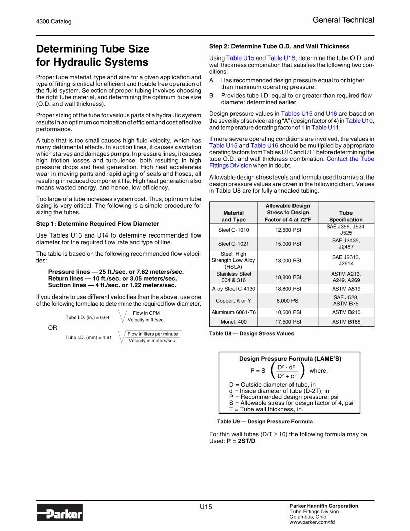
Allowable design stress levels and formula used to arrive at thedesign pressure values are given in the following chart. Valuesin Table U8 are for fully annealed tubing.
Table U8 — Design Stress Values
Design Pressure Formula (LAME’S)D2 - d2
D2 + d2
D = Outside diameter of tube, ind = Inside diameter of tube (D-2T), inP = Recommended design pressure, psiS = Allowable stress for design factor of 4, psiT = Tube wall thickness, in.
Table U9 — Design Pressure Formula
For thin wall tubes (D/T ≥ 10) the following formula may beUsed: P = 2ST/D
P = S ( ) where:
Material and Type
Allowable Design Stress fo Design
Factor of 4 at 72°FTube
Specification
Steel C-1010 12,500 PSISAE J356, J524,
J525
Steel C-1021 15,000 PSISAE J2435,
J2467Steel, High
Strength Low Alloy(HSLA)
18,000 PSISAE J2613,
J2614
Stainless Steel 304 & 316 18,800 PSI
ASTM A213, A249, A269
Alloy Steel C-4130 18,800 PSI ASTM A519
Copper, K or Y 6,000 PSISAE J528, ASTM B75
Aluminum 6061-T6 10,500 PSI ASTM B210
Monel, 400 17,500 PSI ASTM B165

U16 Parker Hannifin CorporationTube Fittings DivisionColumbus, Ohiowww.parker.com/tfd
4300 Catalog General Technical
1. Selecting Tube Material: Table U7 indicates that carbonsteel, C-1010, tubing would meet the media, operatingtemperature range, and maximum operating pressure (high)requirements.
2. Sizing the Tube: From Table U13, the recommended flowdiameters for various lines for 10 GPM flow rate are: 0.405for pressure line, 0.639 for return line, and 1.012 for suctionline.Now, using Table U15 and Table U16, we need to find tubeswith inside diameters (I.D.) equal to or larger than the aboveflow diameters, and wall thicknesses appropriate for designpressures of 3500 psi minimum for the pressure line andabout 500 psi for return and suction lines. Since deratingfactors for Severity of Service (Table U10) and Max. Oper-ating Temperature (Table U11) are both 1, design pressurevalues in Table U15 and Table U16 do not need to bereduced.Matching tube I.D.s and design pressures in Table U15 andTable U16 for above conditions, we find:
A) For the pressure line, we would choose 5/8" O.D. x.083" wall tubing. The .095" and .109" wall tubeswould also be satisfactory if .083" wall is not readilyavailable.
B) For the return line, either 3/4" x .035" or 3/4" x .049"would meet the requirements. If Ferulok fittings arebeing used, we will need to go to 3/4" x .065" because.065" is the smallest wall thickness recommended for3/4" O.D. tubing used with Ferulok fittings in TableU14. This reduces the flow diameter about 3% belowthe recommended value, but is still in the acceptablerange. The alternative is to go to 7/8" O.D. x .072" walltubing, which is way too large.
The design factor is generally applied to ultimate strength ofmaterial (or burst pressure of tubing) to provide a measure ofsafety against the unknowns in material and operating condi-tions. The derating factors listed here should be applied directlyto the design pressure values in Table U15 and Table U16 toarrive at maximum recommended working pressures (i.e., multi-ply values in Table U15 and Table U16 by these derating factors).
Besides severity of service, high operating temperature alsoreduces allowable working pressure of the tubing. Tempera-ture derating factors for various tube materials are given in TableU11. Where applicable, derating factors for severity of serviceand temperature should be applied to the design pressure valuesin Table U15 and Table U16 to arrive at the maximum recom-mended working pressure.
Example:Combined derating factor for 316SS tubing for B (severe)service and 500° F. operation is .67 x .9 = .603
Tube Selection Example:
To select tube material and tube sizes for pressure, return andsuction lines for a hydraulic power unit with the following operat-ing parameters known:
Type of fluid: Petroleum base hydraulic fluid
Operating temperature range: -20°F to +140°F.Maximum operating pressure: 3500 psiMaximum flow rate through each line: 10 GPM
Severity of service: A (normal)
Table U10 — Severity of Service Design and Derating Factors
Table U11 — Temperature Derating Factors* for Tubes
* The derating factors are based on allowable design stressvalues at various temperatures per ASME B31.1 code forpressure piping (1986).
1) Brazing to attach sleeve can be used for all wall thicknesses. Forflanging tool availability, see page S29.
Table U12 — Recommended “Min./Max” Tube Wall Thickness forCommon Fittings
C) For the suction line, we can use any one of the followingtubes: 1-1/4" O.D. x .049" to .083" wall tube for Triple-Lok or Seal-Lok fittings and 1-1/4" O.D. x .095" walltube for Ferulok fittings.One final consideration in choosing the right wall thick-ness for tubing is bending. If bending without the use ofa mandrel is desired, then wall thicknessof less than 7% of tube O.D. should not be used.
Severity of Service Description
Design Factor
Derating Factor
A (Normal)Moderate mechanical and hydraulic shocks. 4.00 1.00
B (Severe)Severe hydraulic shocks and mechanical strain. 6.00 0.67
C (Hazardous)Hazardous application with severe service conditions. 8.00 0.50
Maximum Operating
Steel C-1010
Stainless Steel Monel
Temperature (degrees F)
and C-4130 304 316 Copper
Aluminum 6061-T6
Type 400
100 1.00 1.00 1.00 1.00 1.00 1.00150 1.00 0.91 1.00 0.85 1.00 0.97200 1.00 0.84 1.00 0.80 1.00 0.94250 1.00 0.79 1.00 0.80 0.94 0.91300 1.00 0.75 1.00 0.78 0.80 0.88350 0.99 0.72 0.99 0.67 0.60 0.86400 0.98 0.69 0.97 0.50 0.43 0.85500 0.96 0.65 0.90 0.84600 0.61 0.85 0.84700 0.59 0.82 0.84800 0.57 0.80 0.83900 0.54 0.781000 0.52 0.771100 0.47 0.621200 0.32 0.37
Tube MaterialSteel
St. Steel Steel
Steel Alloy Steel
St. Steel Copper
SizeCopper
AluminumSt. Steel Monel
Copper Monel
Aluminum Plastics
SteelSt. Steel
O.D. (in.)
O.D.(mm)
Dash Number
SAE37° Flare
Triple-Lok
SAE Flareless Ferulok
SAE O-ring Face Seal Seal-Lok 1) Intru-Lok
MetricFlareless
1/8 4 -2 .010 - .035 .010 - .035 — .012 - .028 0.5 - 13/16 6 -3 .010 - .035 .020 - .049 — .012 - .035 1 - 21/4 8 -4 .020 - .065 .028 - .065 .020 - .083 .020 - .049 1 - 2.55/16 10 -5 .020 - .065 .028 - .065 .020 - .095 .020 - .065 1 - 33/8 12 -6 .020 - .065 .035 - .095 .020 - .109 .028 - .065 1.5 - 3.51/2 14 -8 .028 - .083 .049 - .120 .028 - .148 .035 - .083 1.5 - 45/8 15 -10 .035 - .095 .058 - .120 .035 - .134 .035 - .083 1.5 - 43/4 16 -12 .035 - .109 .065 - .120 .035 - .148 .035 - .095 2 - 47/8 18 -14 .035 - .109 .072 - .120 — .049 - .095 2 - 41 20 -16 .035 - .120 .083 - .148 .035 - .188 .049 - .120 2.5 - 4
1 1/4 22 -20 .049 - .120 .095 - .188 .049 - .220 2.5 - 41 1/2 25 -24 .049 - .120 .095 - .220 .049 - .250 2.5 - 4.5
2 28 -32 .058 - .134 .095 - .220 .065 - .220 2.5 - 4.5
30 2.5 - 535 3 - 538 3 - 642 3.5 - 7
4300 Catalog General Technical
U17 Parker Hannifin CorporationTube Fittings DivisionColumbus, Ohiowww.parker.com/tfd
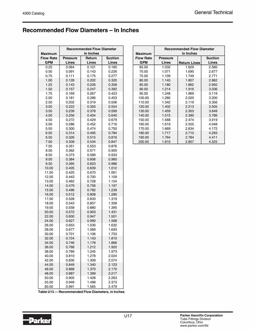
Table U13 — Recommended Flow Diameters, in Inches
Recommended Flow Diameters – In Inches
Maximum MaximumFlow Rate
GPMPressure
LinesReturn Lines
Suction Lines
Flow Rate GPM
Pressure Lines Return Lines
Suction Lines
0.25 0.064 0.101 0.160 65.00 1.032 1.629 2.5800.50 0.091 0.143 0.226 70.00 1.071 1.690 2.6770.75 0.111 0.175 0.277 75.00 1.109 1.749 2.7711.00 0.128 0.202 0.320 80.00 1.145 1.807 2.8621.25 0.143 0.226 0.358 85.00 1.180 1.862 2.9501.50 0.157 0.247 0.392 90.00 1.214 1.916 3.0361.75 0.169 0.267 0.423 95.00 1.248 1.969 3.1192.00 0.181 0.286 0.453 100.00 1.280 2.020 3.2002.50 0.202 0.319 0.506 110.00 1.342 2.119 3.3563.00 0.222 0.350 0.554 120.00 1.402 2.213 3.5053.50 0.239 0.378 0.599 130.00 1.459 2.303 3.6494.00 0.256 0.404 0.640 140.00 1.515 2.390 3.7864.50 0.272 0.429 0.679 150.00 1.568 2.474 3.9195.00 0.286 0.452 0.716 160.00 1.619 2.555 4.0485.50 0.300 0.474 0.750 170.00 1.669 2.634 4.1726.00 0.314 0.495 0.784 180.00 1.717 2.710 4.2936.50 0.326 0.515 0.816 190.00 1.764 2.784 4.4117.00 0.339 0.534 0.847 200.00 1.810 2.857 4.5257.50 0.351 0.553 0.8768.00 0.362 0.571 0.9058.50 0.373 0.589 0.9339.00 0.384 0.606 0.9609.50 0.395 0.623 0.98610.00 0.405 0.639 1.01211.00 0.425 0.670 1.06112.00 0.443 0.700 1.10913.00 0.462 0.728 1.15414.00 0.479 0.756 1.19715.00 0.496 0.782 1.23916.00 0.512 0.808 1.28017.00 0.528 0.833 1.31918.00 0.543 0.857 1.35819.00 0.558 0.880 1.39520.00 0.572 0.903 1.43122.00 0.600 0.947 1.50124.00 0.627 0.990 1.56826.00 0.653 1.030 1.63228.00 0.677 1.069 1.69330.00 0.701 1.106 1.75332.00 0.724 1.143 1.81034.00 0.746 1.178 1.86636.00 0.768 1.212 1.92038.00 0.789 1.245 1.97340.00 0.810 1.278 2.02442.00 0.830 1.309 2.07444.00 0.849 1.340 2.12346.00 0.868 1.370 2.17048.00 0.887 1.399 2.21750.00 0.905 1.428 2.26355.00 0.949 1.498 2.37360.00 0.991 1.565 2.479
Recommended Flow Diameter in Inches
Recommended Flow Diameter in Inches

U18 Parker Hannifin CorporationTube Fittings DivisionColumbus, Ohiowww.parker.com/tfd
4300 Catalog General Technical
Recommended Flow Diameters – In Millimeters
Table U14 — Recommended Flow Diameters, inMillimeters
* LPM = Liters Per Minute
Maximum MaximumRecommended Flow Diameter
in MillimetersFlow Rate
LPM*Pressure
LinesReturn Lines
Suction Lines
Flow Rate LPM*
Pressure Lines
Return Lines
Suction Lines
1 1.670 2.640 4.180 300 28.925 45.726 72.4002 2.362 3.734 5.911 320 29.874 47.226 74.7743 2.893 4.573 7.240 340 30.793 48.679 77.0754 3.340 5.280 8.360 360 31.686 50.090 79.3105 3.734 5.903 9.347 380 32.554 51.463 81.4836 4.091 6.467 10.239 400 33.400 52.800 83.6007 4.418 6.985 11.059 450 35.426 56.003 88.6718 4.723 7.467 11.823 500 37.342 59.032 93.4689 5.010 7.920 12.540 550 39.165 61.913 98.03010 5.281 8.348 13.218 600 40.906 64.667 102.38912 5.785 9.145 14.480 650 42.577 67.307 106.57014 6.249 9.878 15.640 700 44.184 69.848 110.59216 6.680 10.560 16.720 750 45.735 72.299 114.47418 7.085 11.201 17.734 800 47.235 74.670 118.22820 7.468 11.806 18.69422 7.833 12.383 19.60624 8.181 12.933 20.47826 8.515 13.461 21.31428 8.837 13.970 22.11830 9.147 14.460 22.89532 9.447 14.934 23.64634 9.738 15.394 24.37336 10.020 15.840 25.08038 10.295 16.274 25.76740 10.562 16.697 26.43745 11.203 17.710 28.04050 11.809 18.668 29.55755 12.385 19.579 31.00060 12.936 20.449 32.37865 13.464 21.284 33.70070 13.972 22.088 34.97275 14.463 22.863 36.20080 14.937 23.613 37.38785 15.397 24.340 38.53890 15.843 25.045 39.65595 16.277 25.732 40.742100 16.700 26.400 41.800110 17.515 27.689 43.840120 18.294 28.920 45.790130 19.041 30.101 47.659140 19.760 31.237 49.458150 20.453 32.333 51.194160 21.124 33.394 52.873170 21.774 34.421 54.501180 22.405 35.419 56.081190 23.019 36.390 57.617200 23.617 37.335 59.114220 24.770 39.158 61.999240 25.872 40.899 64.756260 26.928 42.569 67.400280 27.944 44.176 69.945
Recommended Flow Diameter in Millimeters

4300 Catalog General Technical
U19 Parker Hannifin CorporationTube Fittings DivisionColumbus, Ohiowww.parker.com/tfd
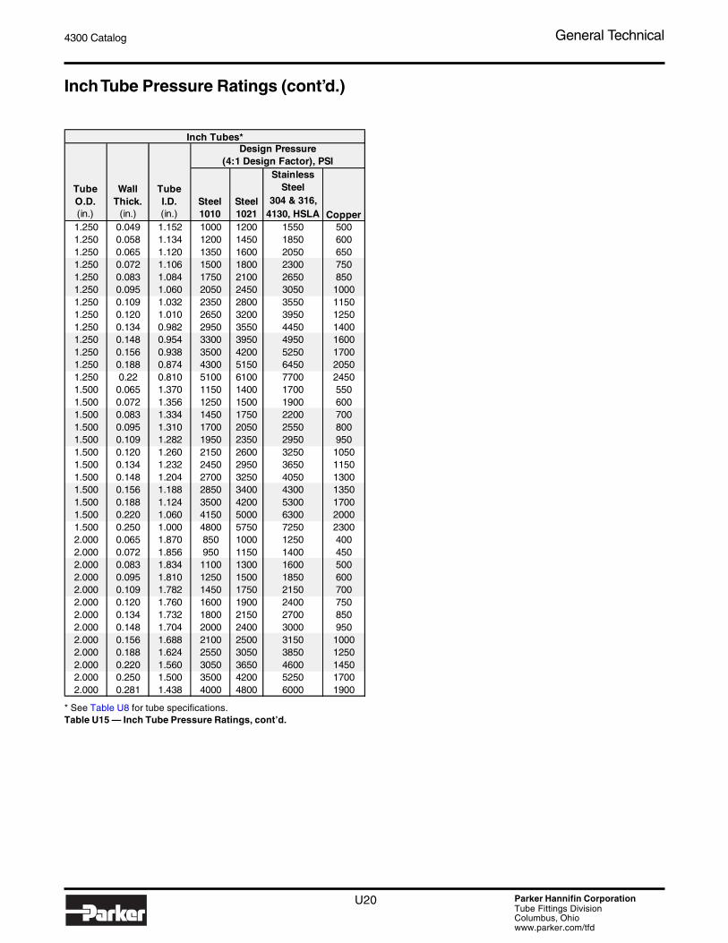
Inch Tube Pressure Ratings
* See Table U8 for tube specifications.Table U15 — Inch Tube Pressure Ratings
0.125 0.010 0.105 2150 2600 3250 1050 0.625 0.028 0.569 1150 1400 1750 5500.125 0.020 0.085 4600 5500 6900 2200 0.625 0.035 0.555 1500 1800 2200 7000.125 0.028 0.069 6650 8000 10000 3200 0.625 0.049 0.527 2100 2500 3200 10000.125 0.035 0.055 8450 10150 12700 4050 0.625 0.058 0.509 2550 3050 3800 12000.188 0.010 0.168 1400 1700 2100 650 0.625 0.065 0.495 2850 3400 4300 13500.188 0.020 0.148 2950 3550 4450 1400 0.625 0.072 0.481 3200 3850 4800 15500.188 0.028 0.132 4250 5100 6400 2050 0.625 0.083 0.459 3750 4500 5650 18000.188 0.035 0.118 5450 6550 8200 2600 0.625 0.095 0.435 4350 5200 6550 21000.188 0.049 0.090 7850 9400 11800 3750 0.625 0.109 0.407 5050 6050 7600 24500.250 0.020 0.210 2150 2600 3250 1050 0.625 0.120 0.385 5600 6700 8450 27000.250 0.028 0.194 3100 3700 4650 1500 0.625 0.134 0.357 6350 7600 9550 30500.250 0.035 0.180 3950 4750 5950 1900 0.750 0.035 0.680 1200 1450 1850 6000.250 0.049 0.152 5750 6900 8650 2750 0.750 0.049 0.652 1750 2100 2600 8500.250 0.058 0.134 6900 8300 10400 3300 0.750 0.058 0.634 2100 2500 3150 10000.250 0.065 0.120 7800 9350 11750 3750 0.750 0.065 0.620 2350 2800 3550 11500.250 0.083 0.084 9950 11950 15000 4800 0.750 0.072 0.606 2650 3200 3950 12500.313 0.020 0.273 1700 2050 2550 800 0.750 0.083 0.584 3050 3650 4600 14500.313 0.028 0.257 2450 2950 3650 1150 0.750 0.095 0.560 3550 4250 5350 17000.313 0.035 0.243 3100 3700 4650 1500 0.750 0.109 0.532 4150 5000 6200 20000.313 0.049 0.215 4500 5400 6750 2150 0.750 0.120 0.510 4600 5500 6900 22000.313 0.058 0.197 5400 6500 8150 2600 0.750 0.134 0.482 5200 6250 7800 25000.313 0.065 0.183 6150 7400 9250 2950 0.750 0.148 0.454 5800 7000 8700 28000.313 0.072 0.169 6850 8200 10350 3300 0.750 0.188 0.374 7500 9000 11300 36000.313 0.083 0.147 8000 9600 12050 3850 0.875 0.035 0.805 1050 1250 1550 5000.313 0.095 0.123 9150 11000 13800 4400 0.875 0.049 0.777 1500 1800 2200 7000.375 0.020 0.335 1400 1700 2100 650 0.875 0.058 0.759 1750 2100 2650 8500.375 0.028 0.319 2000 2400 3000 950 0.875 0.065 0.745 2000 2400 3000 9500.375 0.035 0.305 2550 3050 3850 1200 0.875 0.072 0.731 2200 2650 3350 10500.375 0.049 0.277 3650 4400 5550 1750 0.875 0.083 0.709 2600 3100 3900 12500.375 0.058 0.259 4450 5350 6650 2100 0.875 0.095 0.685 3000 3600 4500 14500.375 0.065 0.245 5000 6000 7550 2400 0.875 0.109 0.657 3500 4200 5250 16500.375 0.072 0.231 5600 6700 8450 2700 0.875 0.120 0.635 3900 4700 5850 18500.375 0.083 0.209 6550 7900 9900 3150 0.875 0.134 0.607 4400 5300 6600 21000.375 0.095 0.185 7600 9100 11450 3650 0.875 0.148 0.579 4900 5900 7350 23500.375 0.109 0.157 8750 10500 13200 4200 1.000 0.035 0.930 900 1100 1350 4500.500 0.028 0.444 1500 1800 2200 700 1.000 0.049 0.902 1300 1550 1950 6000.500 0.035 0.430 1850 2200 2800 900 1.000 0.058 0.884 1550 1850 2300 7500.500 0.049 0.402 2700 3250 4050 1300 1.000 0.065 0.870 1750 2100 2600 8500.500 0.058 0.384 3250 3900 4850 1550 1.000 0.072 0.856 1950 2350 2900 9500.500 0.065 0.370 3650 4400 5500 1750 1.000 0.083 0.834 2250 2700 3400 11000.500 0.072 0.356 4100 4900 6150 1950 1.000 0.095 0.810 2600 3100 3900 12500.500 0.083 0.334 4800 5750 7200 2300 1.000 0.109 0.782 3000 3600 4550 14500.500 0.095 0.310 5550 6650 8350 2650 1.000 0.120 0.760 3350 4000 5050 16000.500 0.109 0.282 6450 7750 9750 3100 1.000 0.134 0.732 3800 4550 5700 18000.500 0.120 0.260 7200 8650 10800 3450 1.000 0.148 0.704 4200 5050 6350 20000.500 0.134 0.232 8050 9650 12150 3850 1.000 0.156 0.688 4450 5350 6700 21500.500 0.148 0.204 8950 10750 13450 4300 1.000 0.188 0.624 5500 6600 8250 26500.500 0.188 0.124 11050 13250 16600 5300 1.000 0.220 0.560 6550 7850 9800 3150
Inch Tubes* Inch Tubes*
TubeO.D.(in.)
WallThick.
(in.)
TubeI.D.(in.)
Design Pressure (4:1 Design Factor), PSI
Steel 1010
Steel1021
Stainless Steel
304 & 316, 4130, HSLA Copper
Steel1021
Stainless Steel
304 & 316, 4130, HSLA Copper
Design Pressure (4:1 Design Factor), PSI
TubeO.D.(in.)
WallThick.
(in.)
TubeI.D.(in.)
Steel 1010
U20 Parker Hannifin CorporationTube Fittings DivisionColumbus, Ohiowww.parker.com/tfd
4300 Catalog General Technical
Inch Tube Pressure Ratings (cont’d.)
* See Table U8 for tube specifications.Table U15 — Inch Tube Pressure Ratings, cont’d.
1.250 0.049 1.152 1000 1200 1550 5001.250 0.058 1.134 1200 1450 1850 6001.250 0.065 1.120 1350 1600 2050 6501.250 0.072 1.106 1500 1800 2300 7501.250 0.083 1.084 1750 2100 2650 8501.250 0.095 1.060 2050 2450 3050 10001.250 0.109 1.032 2350 2800 3550 11501.250 0.120 1.010 2650 3200 3950 12501.250 0.134 0.982 2950 3550 4450 14001.250 0.148 0.954 3300 3950 4950 16001.250 0.156 0.938 3500 4200 5250 17001.250 0.188 0.874 4300 5150 6450 20501.250 0.22 0.810 5100 6100 7700 24501.500 0.065 1.370 1150 1400 1700 5501.500 0.072 1.356 1250 1500 1900 6001.500 0.083 1.334 1450 1750 2200 7001.500 0.095 1.310 1700 2050 2550 8001.500 0.109 1.282 1950 2350 2950 9501.500 0.120 1.260 2150 2600 3250 10501.500 0.134 1.232 2450 2950 3650 11501.500 0.148 1.204 2700 3250 4050 13001.500 0.156 1.188 2850 3400 4300 13501.500 0.188 1.124 3500 4200 5300 17001.500 0.220 1.060 4150 5000 6300 20001.500 0.250 1.000 4800 5750 7250 23002.000 0.065 1.870 850 1000 1250 4002.000 0.072 1.856 950 1150 1400 4502.000 0.083 1.834 1100 1300 1600 5002.000 0.095 1.810 1250 1500 1850 6002.000 0.109 1.782 1450 1750 2150 7002.000 0.120 1.760 1600 1900 2400 7502.000 0.134 1.732 1800 2150 2700 8502.000 0.148 1.704 2000 2400 3000 9502.000 0.156 1.688 2100 2500 3150 10002.000 0.188 1.624 2550 3050 3850 12502.000 0.220 1.560 3050 3650 4600 14502.000 0.250 1.500 3500 4200 5250 17002.000 0.281 1.438 4000 4800 6000 1900
Stainless Steel
304 & 316, 4130, HSLA Copper
Inch Tubes*
TubeO.D.(in.)
WallThick.
(in.)
TubeI.D.(in.)
Design Pressure (4:1 Design Factor), PSI
Steel 1010
Steel1021

4300 Catalog General Technical
U21 Parker Hannifin CorporationTube Fittings DivisionColumbus, Ohiowww.parker.com/tfd
Metric Tube Pressure Ratings
Table U16 — Metric Tube Pressure Ratings
4 0.5 3.0 256 25 4.0 17.0 3194 0.75 2.5 366 25 4.5 16.0 3534 1.0 2.0 465 25 5.0 15.0 3865 0.8 3.5 301 28 1.5 25.0 1175 1.0 3.0 386 28 2.0 24.0 1536 0.75 4.5 256 28 2.5 23.0 1886 1.0 4.0 330 28 3.0 22.0 2236 1.5 3.0 465 28 4.0 20.0 2896 2.0 2.0 585 28 5.0 18.0 3516 2.25 1.5 639 30 2.0 26.0 1438 1.0 6.0 256 30 2.5 25.0 1778 1.5 5.0 366 30 3.0 24.0 2098 2.0 4.0 465 30 4.0 22.0 2718 2.5 3.0 556 30 5.0 20.0 33010 1.0 8.0 209 35 2.0 31.0 12410 1.5 7.0 301 35 2.5 30.0 15310 2.0 6.0 386 35 3.0 29.0 18110 2.5 5.0 465 35 4.0 27.0 23610 3.0 4.0 539 35 5.0 25.0 28912 1.0 10.0 177 35 6.0 23.0 33912 1.5 9.0 256 38 2.5 33.0 14212 2.0 8.0 330 38 3.0 32.0 16812 2.5 7.0 400 38 4.0 30.0 21912 3.0 6.0 465 38 5.0 28.0 26812 3.5 5.0 527 38 6.0 26.0 31514 1.0 12.0 153 38 7.0 24.0 36014 1.5 11.0 223 42 2.0 38.0 10414 2.0 10.0 289 42 3.0 36.0 15314 2.5 9.0 351 42 4.0 34.0 20014 3.0 8.0 410 50 6.0 38.0 24714 3.5 7.0 465 50 9.0 32.0 35314 4.0 6.0 518 65 8.0 49.0 25315 1.0 13.0 143 80 10.0 60.0 25615 1.5 12.0 20915 2.0 11.0 27115 2.5 10.0 33015 3.0 9.0 38616 1.0 14.0 13516 1.5 13.0 19716 2.0 12.0 25616 2.5 11.0 31216 3.0 10.0 36618 1.0 16.0 12118 1.5 15.0 17718 2.0 14.0 23018 2.5 13.0 28118 3.0 12.0 33020 1.5 17.0 16020 2.0 16.0 20920 2.5 15.0 25620 3.0 14.0 30120 3.5 13.0 34520 4.0 12.0 38622 1.0 20.0 10022 1.5 19.0 14622 2.0 18.0 19222 2.5 17.0 23522 3.0 16.0 27725 2.0 21.0 17025 2.5 20.0 20925 3.0 19.0 247
TubeI.D.
(mm)
Design Pressure (Bar)
Steel Low-Carbon
St. 37-4
Stainless Steel1.4571
Metric Tubes Metric Tubes
TubeO.D.(mm)
WallThick.(mm)
TubeI.D.
(mm)
Design Pressure (Bar)
TubeO.D.(mm)
WallThick.(mm)
313409522376432333389549692757333431549658282373478576666235353409495576651201302403
282376
188
434507676641
409478176264353386452157235313392409
128192
212282353373
235
437
282338
266320385226
426478
302403434188
478151201252
282376409161201242322403419186223297371390446134
347353
201269338437
394
Steel Low-Carbon
St. 37-4
Stainless Steel
1.4571
U22 Parker Hannifin CorporationTube Fittings DivisionColumbus, Ohiowww.parker.com/tfd
4300 Catalog General Technical
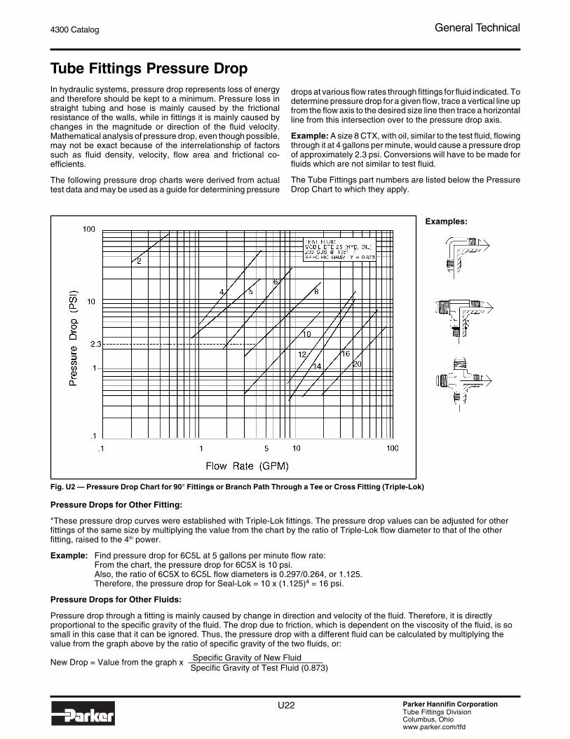
Tube Fittings Pressure DropIn hydraulic systems, pressure drop represents loss of energyand therefore should be kept to a minimum. Pressure loss instraight tubing and hose is mainly caused by the frictionalresistance of the walls, while in fittings it is mainly caused bychanges in the magnitude or direction of the fluid velocity.Mathematical analysis of pressure drop, even though possible,may not be exact because of the interrelationship of factorssuch as fluid density, velocity, flow area and frictional co-efficients.
The following pressure drop charts were derived from actualtest data and may be used as a guide for determining pressure
Examples:
drops at various flow rates through fittings for fluid indicated. Todetermine pressure drop for a given flow, trace a vertical line upfrom the flow axis to the desired size line then trace a horizontalline from this intersection over to the pressure drop axis.
Example: A size 8 CTX, with oil, similar to the test fluid, flowingthrough it at 4 gallons per minute, would cause a pressure dropof approximately 2.3 psi. Conversions will have to be made forfluids which are not similar to test fluid.
The Tube Fittings part numbers are listed below the PressureDrop Chart to which they apply.
Fig. U2 — Pressure Drop Chart for 90° Fittings or Branch Path Through a Tee or Cross Fitting (Triple-Lok)
Pressure Drops for Other Fitting:
*These pressure drop curves were established with Triple-Lok fittings. The pressure drop values can be adjusted for otherfittings of the same size by multiplying the value from the chart by the ratio of Triple-Lok flow diameter to that of the otherfitting, raised to the 4th power.
Example: Find pressure drop for 6C5L at 5 gallons per minute flow rate:From the chart, the pressure drop for 6C5X is 10 psi.Also, the ratio of 6C5X to 6C5L flow diameters is 0.297/0.264, or 1.125.Therefore, the pressure drop for Seal-Lok = 10 x (1.125)4 = 16 psi.
Pressure Drops for Other Fluids:
Pressure drop through a fitting is mainly caused by change in direction and velocity of the fluid. Therefore, it is directlyproportional to the specific gravity of the fluid. The drop due to friction, which is dependent on the viscosity of the fluid, is sosmall in this case that it can be ignored. Thus, the pressure drop with a different fluid can be calculated by multiplying thevalue from the graph above by the ratio of specific gravity of the two fluids, or:
New Drop = Value from the graph x Specific Gravity of New Fluid Specific Gravity of Test Fluid (0.873)

4300 Catalog General Technical
U23 Parker Hannifin CorporationTube Fittings DivisionColumbus, Ohiowww.parker.com/tfd
Examples:
Fig. U3 — Pressure Drop Chart for Straight Fittings and Run Legs of Tees andCrosses (Triple-Lok)
Example:
Fig. U4 — Pressure Drop Chart for 45° Elbow Fittings (Triple-Lok)

U24 Parker Hannifin CorporationTube Fittings DivisionColumbus, Ohiowww.parker.com/tfd
4300 Catalog General Technical
Fitting and Adapter PressureRatingsPressure Ratings
Pressure ratings shown on the product pages of this catalog arefor dynamic systems. A vast majority of systems where ourfittings are used fall in this category. However, there areapplications, such as hydraulic jacks, where the system pres-sure is essentially static once it is pressurized. For this type ofan application the fittings can be used at higher pressures.
The dynamic and static systems can be defined as follows:
Dynamic: A system in which the operating pressure fluctuates,in accordance with load, up to a maximum pressure limited bythe relief valve. In addition, the system may also experienceshocks, vibration and temperature excursions. Example: Abackhoe.
Static: A system, once pressurized, is essentially free ofpressure fluctuations, shock, vibration and temperature excur-sions, with such pressurizations not exceeding 30,000 in thelife of the system. Example: A hydraulic jack.
The dynamic pressure ratings are based on a minimum designfactor of 4. In other words, the fitting is capable of holding apressure equal to 4 times the rated pressure before leakage orfailure. For static applications, the design factor can be 3.Hence, the static rating can be determined by multiplying thedynamic rating by 1.33.
Static pressure rating = 1.33 x Dynamic pressure rating
Example: Static pressure rating for a fitting rated at 6000 psi =1.33 x 6000 = 8000 psi
Higher (dynamic) Ratings
Some Triple-Lok parts are capable of performing at higherpressures than those shown on the product pages. For infor-mation on higher ratings, contact Tube Fittings Division.

4300 Catalog General Technical
U25 Parker Hannifin CorporationTube Fittings DivisionColumbus, Ohiowww.parker.com/tfd
ISO 6149-1 — Metric Straight Thread O-Ring Port(SAE 2244-1/DIN 3852, Part 3) Metric ISO 261, “M” Thread
Thread Large Small d34) d4 d5 d6 L1 L25) L3 L4 Z°Size d22) d23) Parker
+ 0.1 +0.5 +0.4 min max min full ±1° O-ringd11) min min ref. 0 0 0 thread Size8)
M8 X 1 17 14 3 12.5 9.1 14 1.6 11.5 1 10 12° M8 ISO O-ringM10 X 1 20 16 4.5 14.5 11.1 16 1.6 11.5 1 10 12° M10 ISO O-ring
M12 X 1.5 23 19 6 17.5 13.8 19 2.4 14 1.5 11.5 15° M12 ISO O-ringM14 X 1.56) 25 21 7.5 19.5 15.8 21 2.4 14 1.5 11.5 15° M14 ISO O-ringM16 X 1.5 28 24 9 22.5 17.8 24 2.4 15.5 1.5 13 15° M16 ISO O-ringM18 X 1.5 30 26 11 24.5 19.8 26 2.4 17 2 14.5 15° M18 ISO O-ringM22 X 1.5 34 29 14 27.5 23.8 29 2.4 18 2 15.5 15° M22 ISO O-ringM27 X 2 40 34 18 32.5 29.4 34 3.1 22 2 19 15° M27 ISO O-ringM30 X 2 44 38 18 36.5 32.4 38 3.1 22 2 19 15° M30 ISO O-ringM33 X 2 49 43 23 41.5 35.4 43 3.1 22 2.5 19 15° M33 ISO O-ringM42 X 2 60 52 30 50.5 44.4 52 3.1 22.5 2.5 19.5 15° M42 ISO O-ringM48 X 2 66 57 36 55.5 50.4 57 3.1 25 2.5 22 15° M48 ISO O-ringM60 X 2 76 67 44 65.5 62.4 67 3.1 27.5 2.5 24.5 15° M60 ISO O-ring
FOR CARTRIDGE VALVE CAVITIES ONLY (SEE ISO 7789)
M20X1.57) 32 27 — 25.5 21.8 27 2.4 — 2 14.5 15° M20 ISO O-ring
Table U17— Port Detail — ISO 6149-1
1) Per ISO 261 tolerance class 6H. Tap drill per ISO 2306 class 6H.2) Spotface diameter with the optional identification ridge.3) Spotface diameter without identification ridge. Port to be identified by marking “metric” next to it or “ISO 6149-1 Metric” on
component name plate.4) Reference only. Connecting hole application may require a different size.5) Tap drill depths given require use of a bottoming tap to produce the specified full thread lengths.
Where standard taps are used, increase tap drill depths accordingly.6) Preferred for diagnostic port applications.7) For cartridge valve cavity applications only.8) 90 durometer nitrile is standard for hydraulic applications.
NOTE: For port tapping tools, see pages S40 and S41. See page T8 for assembly torques.
U26 Parker Hannifin CorporationTube Fittings DivisionColumbus, Ohiowww.parker.com/tfd
4300 Catalog General Technical
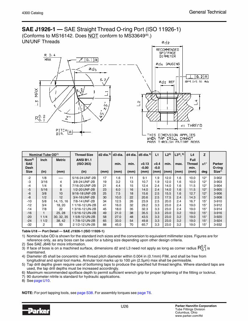
SAE J1926-1 — SAE Straight Thread O-ring Port (ISO 11926-1)(Conforms to MS16142. Does NOT conform to MS33649(8).)UN/UNF Threads
Nominal Tube OD1) Thread Size d2 dia.3) d3 dia. d4 dia. d5 dia.4) L1 L25) L33), 6) L4 Z
Nom2) Inch Metric ANSI B1.1 FullSAE (ISO 263) min. min. +0.13 +0.4 min. max. Thread ±1° ParkerDash -0.00 -0.0 min. O-ringSize (in) (mm) (in) (mm) (mm) (mm) (mm) (mm) (mm) (mm) (mm) deg Size7)
-2 1/8 —- 5/16-24 UNF-2B 17 1.6 11 9.1 1.9 12.0 1.6 10.0 12° 3-902-3 3/16 4 3/8-24 UNF-2B 19 3.2 13 10.7 1.9 12.0 1.6 10.0 12° 3-903-4 1/4 6 7/16-20 UNF-2B 21 4.4 15 12.4 2.4 14.0 1.6 11.5 12° 3-904-5 5/16 8 1/2-20 UNF-2B 23 6.0 16 14.0 2.4 14.0 1.6 11.5 12° 3-905-6 3/8 10 9/16-18 UNF-2B 25 7.5 18 15.6 2.5 15.5 1.6 12.7 12° 3-906-8 1/2 12 3/4-16 UNF-2B 30 10.0 22 20.6 2.5 17.5 2.4 14.3 15° 3-908-10 5/8 14, 15, 16 7/8-14 UNF-2B 34 12.5 26 23.9 2.5 20.0 2.4 16.7 15° 3-910-12 3/4 18, 20 1 1/16-12 UN-2B 41 16.0 32 29.2 3.3 23.0 2.4 19.0 15° 3-912-14 7/8 22 1 3/16-12 UN-2B 45 18.0 35 32.3 3.3 23.0 2.4 19.0 15° 3-914-16 1 25, 28 1 5/16-12 UN-2B 49 21.0 38 35.5 3.3 23.0 3.2 19.0 15° 3-916-20 1 1/4 30, 32, 35 1 5/8-12 UN-2B 58 27.0 48 43.5 3.3 23.0 3.2 19.0 15° 3-920-24 1 1/2 38, 42 1 7/8-12 UN-2B 65 33.0 54 49.8 3.3 23.0 3.2 19.0 15° 3-924-32 2 50 2 1/2-12 UN-2B 88 45.0 70 65.7 3.3 23.0 3.2 19.0 15° 3-932
Table U18 — Port Detail — SAE J1926-1 (ISO 11926-1)
1) Nominal tube OD is shown for the standard inch sizes and the conversion to equivalent millimeter sizes. Figures are forreference only, as any boss can be used for a tubing size depending upon other design criteria.
2) See SAE J846 for more information.3) If face of boss is on a machined surface, dimensions d2 and L3 need not apply as long as corner radius R0.2 is
maintained.4) Diameter d5 shall be concentric with thread pitch diameter within 0.004 in (0.1mm) FIM, and shall be free from
longitudinal and spiral tool marks. Annular tool marks up to 100 µin (2.5µm) max shall be permissible.5) Tap drill depths given require use of bottoming taps to produce the specified full thread lengths. Where standard taps are
used, the tap drill depths must be increased accordingly.6) Maximum recommended spotface depth to permit sufficient wrench grip for proper tightening of the fitting or locknut.7) 90 durometer nitrile is standard for hydraulic applications.8) See page U10.
NOTE: For port tapping tools, see page S38. For assembly torques see page T6.
0.1
4300 Catalog General Technical
U27 Parker Hannifin CorporationTube Fittings DivisionColumbus, Ohiowww.parker.com/tfd
SAE Straight Thread ConnectorUse in MS33649SAE straight thread connectors, such as Parker F5OX, need aspecial hex chamfer of 35° to a controlled diameter to functionproperly in MS33649 port. In the past, when MS33649 wasmore popular, Parker fittings were made with this chamfer.However, this port has been superseded by SAE J1926-1 inindustrial applications for over 50 years.
Since J1926-1 is a superior design, Parker, along with othermanufacturers, discourages the use of MS33649 port in non-aircraft applications. In fact, a chamfer modification require-ment for MS33649 will not be in the next printing of the SAEJ514 specification, again to discourage the use of this port.
If you must use this port, you have to request fittings with thisspecial chamfer requirement, which makes them special andmore expensive.

U28 Parker Hannifin CorporationTube Fittings DivisionColumbus, Ohiowww.parker.com/tfd
4300 Catalog General Technical
ISO 6162 — Four-Bolt Flange Connection (Includes SAE J518)
NOTE: For assembly procedure and torques, see page T8.
Nominal 2.5 to 31.5 MPa Series1)
Flange (SAE Code 61) O-Rings3)
Size Clamping Screws Flange Half and Bolt Pattern
D3 Screw Holes Parker
Type I Type II2) (SAE J518) C J W Y L5 L6 ISO 3601-1 O-Ring
(in) (mm) Thread t1 Min. depth Thread (UNC) t1 Min. depth ± 0.25 max. min. ±0.25 Ref. ID x Section Size
1/2 13 M8 x 1.25 12.5 5/16 - 18 24 38.1 54.9 53.1 17.5 46 13 19 19 x 3.55 2-210 3/4 19 M10 x 1.5 16.5 3/8 - 16 22 47.6 65.8 64.3 22.3 52 14 22 25 x 3.55 2-214
1 25 M10 x 1.5 14.5 3/8 - 16 22 52.4 70.6 69.1 26.2 59 16 22 32.5 x 3.55 2-2191 1/4 32 M10 x 1.5 16.5 7/16 - 14 28 58.7 80.3 78.5 30.2 73 144) 24 37.5 x 3.55 2-2221 1/2 38 M12 x 1.75 19.5 1/2 - 13 27 69.9 94.5 93.0 35.7 83 16 25 47.5 x 3.55 2-225
2 51 M12 x 1.75 19.5 1/2 - 13 27 77.8 103.1 100.1 42.9 97 16 26 56 x 3.55 2-2282 1/2 64 M12 x 1.75 21.5 1/2 - 13 30 88.9 115.8 112.8 50.8 109 19 38 69 x 3.55 2-232
3 76 M16 x 2 28.5 5/8 - 11 30 106.4 136.7 133.4 61.9 131 22 41 85 x 3.55 2-2373 1/2 89 M16 x 2 28.5 5/8 - 11 33 120.7 153.9 150.9 69.9 140 22 28 97.5 x 3.55 2-241
4 102 M16 x 2 25.5 5/8 - 11 30 130.2 163.6 160.3 77.8 152 25 35 112 x 3.55 2-2455 127 M16 x 2 27.5 5/8 - 11 33 152.4 182.6 185.7 92.1 181 28 41 136 x 3.55 2-253
Nominal 40 MPa Series1)
Flange (SAE Code 62) O-Rings3)
Size Clamping Screws Flange Half and Bolt PatternD3 Screw Holes Parker
Type I Type II2) (SAE J518) C J W Y L5 L6 ISO 3601-1 O-Ring
(in) (mm) Thread t1 Min. depth Thread (UNC) t1 Min. depth ± 0.25 max. min. ±0.25 Ref. ID x Section Size
1/2 13 M8 x 1.25 14.5 5/16 - 18 21 40.5 57.2 55.6 18.2 48 16 22 19 x 3.55 2-210 3/4 19 M10 x 1.5 16.5 3/8 - 16 24 50.8 72.1 70.6 23.8 60 19 28 25 x 3.55 2-214
1 25 M12 x 1.75 21.5 7/16 - 14 27 57.2 81.8 80.3 27.8 70 24 33 32.5 x 3.55 2-2191 1/4 32 M12 x 1.75 18.5 1/2 - 13 25 66.6 96.0 94.5 31.8 78 27 38 37.5 x 3.55 2-2221 1/2 38 M16 x 2 25.5 5/8 - 11 35 79.3 114.3 111.3 36.5 95 30 43 47.5 x 3.55 2-225
2 51 M20 x 2.5 33.5 3/4 - 10 38 96.8 134.9 131.8 44.5 114 37 52 56 x 3.55 2-228
Table U19 — Port Detail — ISO 6162
1) 1 MPa = 10 bar = 145 PSI.2) Not for new design.3) 90 durometer nitrile is standard for hydraulic applications.4) 16 mm is also acceptable.

4300 Catalog General Technical
U29 Parker Hannifin CorporationTube Fittings DivisionColumbus, Ohiowww.parker.com/tfd
ElastomericSeal Ring
Seal Type “E”
Special ElastomericSeal Ring
Seal Type “E”
O-Ring withRetaining RingTypes “G” & “H”
Cutting FaceSeal Type “B”
Bonded WasherSeal
Metal-to-MetalSeal
Seal Ring O-Ring
RetainingRing
O-Ring
Back-UpWasher
BondedWasher
Locknut
O-Ring RigidSeal Type “G”
O-Ring AdjustableSeal Type “H”
Cutting FaceSeal Type “B”
Bonded Washer(e.g. Dowty) Seal
Min. FullThread
ThreadPitch Dia.
Ra 3.20.2
45°L1 Max.
Cutting Face
L 2
D3
D4
Port Sealing Methods
ISO 1179-11) — Flat Face Port with British Standard Pipe, Parallel (BSPP) Threads(DIN 3852, Part 2)ISO 228-1 “G” Threads
Table U20 — Port Detail — ISO 1179-1
1) Conforms to proposed revision.2) 90 durometer nitrile is standard for hydraulic applications.3) See page O5 for O-ring and retaining ring ordering information.4) See page O6 for details.
EOlastic Seal (Type E)
NarrowTypes B & E
WideTypes G & H Part Number
Parker O-Ring Size2
O-Ring I.D. x Section (mm)
Retaining Ring Part Number
G 1/8-28 9.9 15 17.2 1.0 8.5 ED10X1X 5-585 7.98 x 1.88 1/8 Retaining Ring D9DT-2G 1/4-19 13.3 20 20.7 1.5 12.5 ED14X1.5X 2-111 10.77 x 2.62 1/4 Retaining Ring D9DT-4G 3/8 19 16.8 23 24.5 2.0 12.5 EDR3/8X 2-113 13.94 x 2.62 3/8 Retaining Ring D9DT-6G 1/2-14 21.1 28 34.0 2.5 14.5 EDR1/2X 5-256 17.96 x 2.62 1/2 Retaining Ring D9DT-8G 3/4-14 26.6 33 40.0 2.5 16.5 ED26X1.5X 2-119 23.47 x 2.62 3/4 Retaining Ring D9DT-10G 1-11 33.5 41 46.1 2.5 18.5 ED33X2X 2-217 29.74 x 3.53 1 Retaining Ring D9DT-12
G 1 1/4-11 42.2 51 54.0 2.5 20.5 ED42X2X 2-222 37.69 x 3.53 1 1/4 Retaining Ring D9DT-16G 1 1/2-11 48.1 56 60.5 2.5 22.5 ED48X2X 2-224 44.04 x 3.53 1 1/2 Retaining Ring D9DT-20
G 2-11 59.9 69 73.3 3.0 26.0 — — — — D9DT-24
L2 min.
(mm)
Bonded Washer
Part No.4
O-Ring and Retaining Ring (Types G & H)3
Thread Size
(ISO 228-1)D3
(mm)
D4 (mm)
L1 max. (mm)

U30 Parker Hannifin CorporationTube Fittings DivisionColumbus, Ohiowww.parker.com/tfd
4300 Catalog General Technical
ISO 9974-1 — Flat Face Port with Metric Threads(DIN 3852, Part 1)Metric ISO261, “M” Thread
Thead D 3 D 4 L 1 L 2 W EOlastic Seal (Type E) O-ring and Retaining Ring1)
Size max. min. O-ring O-ring ID x section Retaining Ring(ISO 261) (mm) (mm) (mm) (mm) (mm) Part no. Size2) (mm) Part No.
M8 x 1 8 +0.2 13 1 8 ED8X1X 3-902 6.07 x 1.63 M8 RRM10 x 1 10 +0.2 15 1 8 ED10X1X 6-074 8.00 x 1.50 M10 RR
M12 x 1.5 12 +0.2 18 1.5 12 ED12X1.5X 2-012 9.25 x 1.78 M12 RRM14 x 1.5 14 +o.2 20 1.5 12 0.1 ED14X1.5X 2-013 10.82 x 1.78 M14 RRM16 x 1.5 16 +0.2 23 1.5 12 ED16X1.5X 3-907 13.46 x 2.08 M16 RRM18 x 1.5 18 +0.2 25 2 12 ED18X1.5XX 2-114 15.54 x 2.62 M18 RR
M20 x 1.53) 20 +0.2 27 2 14 ED20X1.5X 2-017 17.17 x 1.78 M20 RRM22 x 1.5 22 +0.2 28 2.5 14 ED22X1.5X 2-018 18.77 x 1.78 M22 RR
M24 x 1.54) 26 +0.2 30 2.5 14 — 2-019 20.35 x 1.78 M24 RRM26 x 1.5 26 +0.2 33 2.5 16 ED26X1.5X 2-118 21.89 x 2.62 M26 RRM27 x 2 27 +0.2 33 2.5 16 ED26X1.5X 2-119 23.47 x 2.62 M27 RRM33 x 2 33 +0.3 41 2.5 18 0.2 ED33X2X 2-122 28.24 x 2.62 M33 RR
M36 x 24) 36 +0.3 43 2.5 18 — 2-124 31.42 x 2.62 M36 RRM42 x 2 42 +0.3 51 2.5 20 ED42X2X 2-128 37.77 x 2.62 M42 RR
M45 x 24) 45 +0.3 50 2.5 20 — 2-130 40.94 x 2.62 M45 RRM48 x 2 48 +0.3 56 2.5 22 ED48X2X 2-132 44.12 x 2.62 M48 RR
Table U21 — Port Detail — ISO 9974-1
1) Seal types G and H are not covered in ISO 9974-1. See page O4 for retaining ring and O-ring ordering information.2) 90 durometer nitrile is standard for hydraulic applications.3) For diagnostic applications.4) These sizes are not covered in ISO 9974-1.
ISO 9974 Port seal types available from Parker
RetainingRing
EOlasticSeal Ring
ElastomericSeal Ring
Seal Type E
Special ElastomericSeal Ring
Seal Type E
O-Ring Rigid
Seal Type G1)
O-Ring withRetaining RingTypes G & H3)
O-Ring Adjustable
Seal Type H1)
Cutting Face
Seal Type B
Cutting FaceSeal Type B
O-Ring O-Ring
Back UpWasher
Locknut
CuttingFace
Y ZX
D4
D3
45°
L1Max.
Ra 3.2W A
L2Min. FullThread
A
ThreadPitch Dia.
Metal-To-MetalSeal
X Y Z
(See Note 1)

4300 Catalog General Technical
U31 Parker Hannifin CorporationTube Fittings DivisionColumbus, Ohiowww.parker.com/tfd
NPTF and BSPT Dimensions
Male NPTF
Female NPTF
Table U22 — NPTF Dimensions
1) For bottoming taps only.
Table U23 — BSPT Dimensions
1) For bottoming taps only.
Male BSPT
Female BSPT
ThreadSize
NPTF
O.D.Male Thread Large Dia.
D Min.ThreadLength
B Min.Tap DrillDepth 1)
EChmf.Dia.
1/8-27 0.41 0.31 0.38 0.42
1/4-18 0.55 0.44 0.47 0.55
3/8-18 0.68 0.47 0.53 0.69
1/2-14 0.85 0.59 0.69 0.85
3/4-14 1.06 0.63 0.75 1.06
1-11 1/2 1.33 0.75 0.84 1.34
1 1/4-11 1/2 1.67 0.78 0.84 1.68
1 1/2-11 1/2 1.91 0.81 0.88 1.92
2-11 1/2 2.39 0.81 0.91 2.39
ThreadSizeBSPT
O.D.Male Thread Large Dia.
D Min.ThreadLength
B Min.Tap DrillDepth 1)
EChmf.Dia.
1/8-28 0.39 0.31 0.38 0.42
1/4-19 0.53 0.44 0.47 0.55
3/8-19 0.67 0.47 0.53 0.69
1/2-14 0.84 0.59 0.69 0.85
3/4-14 1.06 0.63 0.75 1.06
1-11 1.33 0.75 0.84 1.34
1 1/4-11 1.67 0.78 0.84 1.68
1 1/2-11 1.90 0.81 0.88 1.92
2-11 2.37 0.81 0.91 2.39

U32 Parker Hannifin CorporationTube Fittings DivisionColumbus, Ohiowww.parker.com/tfd
4300 Catalog General Technical
Tube to Port1) Pairing for Medium Pressure2) Applications
Table U24 — Tube to Port Pairing for Medium Pressure Applications
Notes:1) Ports are in accordance with the standards listed below:
SAE J1926-1, ISO 6149-1, NPTF-SAE J476 and BSPP-ISO 1179-12) The pressure range covering all the sizes shown is 1000 to 5000 PSI.
Table U25 — Tube to Port Pairing for High Pressure Applications
Notes:1) Ports are in accordance with the standards listed below.
SAE J1926-1, ISO 6149-1, NPTF-SAE J476 and BSPP-ISO 1179-12) Pressure range covering all sizes shown is 2500 to 9000 PSI.
Tube to Port1) Pairing for High Pressure2) Applications
1/8 (-2) 4 5/16-24 M8 x 1 1/16-27 G 1/8-283/16 (-3) 5 3/8-24 M10 x 1 1/8-27 G 1/8-281/4 (-4) 6 7/16-20 M10 x 1 1/8-27 G 1/8-285/16 (-5) 8 1/2-20 M12 x 1.5 1/8-27 G 1/4-193/8 (-6) 10 9/16-20 M14 x 1.5 1/4-18 G 1/4-191/2 (-8) 12 3/4-16 M16 x 1.5 3/8-18 G 3/8-19— 15 3/4-16 M18 x 1.5 1/2-14 G 1/2-145/8 (-10) 16, 18 7/8-14 M22 x 1.5 1/2-14 G 1/2-143/4 (-12) 20 1 1/16-12 M27 x 2 3/4-14 G 3/4-147/8 (-14) 22 1 3/16-12 M27 x 2 3/4-14 G 3/4-141 (-16) 25, 28 1 5/16-12 M33 x 2 1-11 1/2 G 1-11
1 1/4 (-20) 30, 35 1 5/8-12 M42 x 2 1 1/4-11 1/2 G 1 1/4-111 1/2 (-24) 38, 42 1 7/8-12 M48 x 2 1 1/2-11 1/2 G 1 1/2-11
2 (-32) 50 2 1/2-12 M60 x 2 2-11 1/2 G 2-11
Tube O.D. Port Thread
ISO NPTF BSPPInch
(Dash Size)Metric (mm) SAE
1/8 (-2) 4 5/16-24 M8 x 1 1/16-27 G 1/8-283/16 (-3) 5 3/8-24 M10 x 1 1/8-27 G 1/8-281/4 (-4) 6 7/16-20 M12 x 1.5 1/8-27 G 1/8-285/16 (-5) 8 1/2-20 M14 x 1.5 1/8-27 G 1/4-193/8 (-6) 10 9/16-20 M16 x 1.5 1/4-18 G 3/8-191/2 (-8) 12 3/4-16 M18 x 1.5 3/8-18 G 3/8-195/8 (-10) 14, 16 7/8-14 M22 x 1.5 1/2-14 G 1/2-143/4 (-12) 20 1 1/16-12 M27 x 2 3/4-14 G 3/4-147/8 (-14) — 1 3/16-12 M30 x 2 3/4-14 G 3/4-141 (-16) 25 1 5/16-12 M33 x 2 1-11 1/2 G 1-11
1 1/4 (-20) 30 1 5/8-12 M42 x 2 1 1/4-11 1/2 G 1 1/4-111 1/2 (-24) 38 1 7/8-12 M48 x 2 1 1/2-11 1/2 G 1 1/2-11
2 (-32) 50 2 1/2-12 M60 x 2 2-11 1/2 —
ISO NPTF BSPP
Tube O.D. Port ThreadInch
(Dash Size)Metric (mm) SAE


