

GeneralSpecifications
<<Contents>> <<Index>>
YFGW510Field Wireless Access Point
Yokogawa Electric Corporation2-9-32, Nakacho, Musashino-shi, Tokyo, 180-8750 JapanTel.: 81-422-52-5690 Fax.: 81-422-52-2018
GS 01W02E01-01EN
GS 01W02E01-01EN1st Edition July 2012 (KP)3rd Edition May 2013 (KP)
GENERALThis General Specification(GS) describes the hardware specifications for Field Wireless Management Station and specifications of attached software. This product is based on wireless communications standard ISA100.11a for industrial automation of International Society of Automation (ISA). This product has backbone router function based on ISA100.11a, and combining this with Field Wireless Management Station (YFGW410) and/or Field Wireless Media Converter (YFGW610) composes the field wireless system. For outline of a field wireless system, and details of each product, see related product General Specifications.
FEATURES●�High-performance,�compact�industrial�wireless�access�pointThis product is an industrial wireless access point, compact and lightweight and supporting multiple wireless standards. Enabling you to build a robust field wireless network, the access point provides reliable communication.●Duocast�(ISA100.11a�Standard)�This product supports the “Duocast” function of ISA100.11a standard. Enabling simultaneous communication with two YFGW510s, thereby creating a redundant communication path, increasing the reliability of the field wireless network.●Wireless�LAN�(IEEE802.11a/b/g)�This product has a dual band wireless LAN communication Function (2.4 GHz and 5 GHz) in a field wireless backbone. The wireless LAN in field wireless backbone enables a design flexible to the field wireless network of a wide area.

2
All Rights Reserved. Copyright © 2012, Yokogawa Electric Corporation
<<Contents>> <<Index>>
GS 01W02E01-01EN May 31, 2013-00
■� PerformanceNetwork�Size:�
Max 100 field wireless devices are connectableDisplay:�
2-color luminescence LED displays the operating state of this product, and the operating state of wireless communications and cable communications.
Diagnosis�Functions:�CPU failures, communication interface malfunctions, outside the range, abnormal settings.
Software�Download�Function:�The software inside this product and the software (communication firmware, sensor firmware) inside wireless field device can update via YFGW410.
■� Installation�EnvironmentTemperature�Range:�
Operating: -40 to +65°C (altitude: up to 3000 m)Storage: -40 to +85°C
Humidity�Range:Operating: 5 to 95% RH (non-condensation)Storage: 5 to 95% RH (non-condensation)
Temperature�Gradient:Operating: ±10°C/h or lessStorage: ±20°C/h or less
Power�Supply:Voltage Range : 10.0-26.4 V DCRated Voltage: 24 V DCMomentary Power Failure: Instant DisconnectionDC Power Supply Ripple Ratio: 1%p-p or less
Power�Consumption:Max. 3.5 W
Degrees�of�Protection:IP66, NEMA4X
�HARDWARE�SPECIFICATIONS■� Communication�Interface
Item Field�Network�Specifications Field�Wireless�Backbone�Specifications�*1
CommunicationInterface
Standard IEEE802.15.4 IEEE802.11a/b/g *2 100BASE-TX 100BASE-FXFrequency 2400–2483.5 MHz b/g: 2400-2483.5 MHz
a: 5150-5850 MHz–
Raw data rate 250 kbps 1-54 Mbps 100 Mbps 100 MbpsRadio Security AES128 bit WPA2-PSK –RF Transmitter Power
Max 12 dBm *3 Max 18 dBm *3 –
Connector N type N type RJ-45 SC connector[ single pole × 2 ] *4
Cable Type coaxial coaxial Category 5 Multimode fiber(50/125 μm or 62.5/125 μm)
Antenna +2 dBi – –Remote Antenna +2 dBi, +6 dBi, +9 dBi +2 dBi, +6 dBi, +9 dBi –Maximum length 500 m *5 b/g: 500 m *5
a: 200 m *5100 m 2000 m
Port 1 port Max 2 port 1 port 1 portProtection – – Surge –
CommunicationProtocol
Field Wireless ISA100.11a –Management, configuration, etc.
– IEEE1588PTP v2 *6, Proprietary *7
*1: In outdoor wiring to Field Network or 100BASE-FX of Field Wireless Backbone, use optical fiber cables with a nonmetallic tension member, combining with YFGW610
*2: This product requires a wireless LAN access point for connection with YFGW410 in the wireless LAN in field wireless backbone.
*3: This is the maximum radio output at N-type connector for antenna connection. Radio output power depends on the region and the antenna type.
*4: 2-pole SC connector cannot be used due to the conduit hole size limitation. SC connector should use Short Boot type. *5: The maximum length needs perfect conditions without an obstruction for radio wave transmission, using a standard
antenna (2 dBi). The maximum length changes with the environmental conditions and installation situations of a site.*6: Installation of these multiple product and YFGW410 in one field wireless subnet requires direct connection or the
connection via IEEE1588PTP basis products.*7: TCP based custom protocol used for communication between this product and YFGW410.

3<<Contents>> <<Index>>
All Rights Reserved. Copyright © 2012, Yokogawa Electric Corporation GS 01W02E01-01EN May 31, 2013-00
Vibration�Resistance:�0.21 mm P-P (10-60 Hz), 3G (60-2k Hz)
Shock�Resistance:�50G 11 ms
Noise�Resistance:�Electric Field: 3 V/m or less (80 MHz-1 GHz) Electrostatic Discharges: 4 kV or less (contact discharge), 8 kV or less(aerial discharge)
Grounding:Class-D grounding (no sharing ground with others)
Cooling:Natural Air Cooling
■� Regulatory�Compliance�StatementsThis device contains the wireless module which satisfies the following standards.
* Please confirm that an installation region fulfills an applicable standard. If additional regulatory information and approvals are required, contact a Yokogawa representative.
Japanese�Radio�Law:Construction Design Attestation Number: 007-AA0011 (ISA100.11a), 007-AA0065/66 (Wireless LAN)
R&TTE�Conformity�Standards:�EN 300 328, EN 301 893, EN60950-1,EN 301 489-1, EN 301 489-17
Regulation�Conformity�of�the�Wireless�Module:�• FCC Approval (Part 15C,Part 15E) • IC Approval (RSS-210)
EMC�Conformity�Standards:EN61326-1 Class A, Table 2 (For use in industrial locations), EN55011 Class A, group 1, EN61000-6-2
Safety�Requirements:EN61010-1, CSA C22.2 No. 61010-1
■� Physical�SpecificationsConnections:�
Refer to “MODEL AND SUFFIX CODES.”Housing�Material:�
Low copper cast aluminum alloy with polyurethane, mint-green paint (Munsell 5.6BG 3.3/2.9 or its equivalent)
Name�Plate�and�Tag:316 SST
Weight:3.0 kg (without mounting bracket, and process connector.)
�SOFTWARE�SPECIFICATIONS■� Field�Wireless�Access�Point�Setting�Tool
This software is used for a setup and maintenance of this product. PC on which this software program installed is connected with this product via infrared communication.
■� Specifications�and�System�RequirementsSoftware�License:�
1 licenseLanguage:�
Software (GUI): EnglishManual: Japanese or English
Hardware�Operating�Environment:�
Item Recommended�System�RequirementProcessor Intel Core 2 Duo 2.66 GHz or moreMemory 2 GB or moreHard Disk 40 GB or more
(Minimum free space 15 GB or more) Display 1280 x 800 High color, 32-bitCommunication Device
Ethernet Network Card
Software�Operating�Environment�*1,*2,*3:�
OS� KindWindows7 Professional Service Pack 1 32/64 bitWindows Vista Business Edition Service Pack 2 32 bitWindows Server 2008 Enterprise Service Pack 2 32 bitWindows Server 2008 R2 Enterprise 32/64 bit
*1: Japanese version and English version are supported.
*2: Microsoft .NET Framework 3.5 Service Pack 1 is required.
*3: For 64 bit OS, WOW64 (Windows 32-bit On Windows 64-bit) can be performed.

4
All Rights Reserved. Copyright © 2012, Yokogawa Electric Corporation
<<Contents>> <<Index>>
GS 01W02E01-01EN May 31, 2013-00
�MODEL�AND�SUFFIX�CODESModel Suffix�Codes Description
YFGW510 �������������������������������������������������������� Field Wireless Access PointOutput signal
-A ���������������������������������������������������� ISA100.11a
-C ���������������������������������������������������� ISA100.11a, IEEE802.11a/b/g *1
Communication interface
1 �������������������������������������������������� 100 BASE-TX
2 �������������������������������������������������� 100 BASE-FX
5 �������������������������������������������������� Wireless LANHousing 1 ���������������������������������������������� Low copper cast aluminum alloyElectrical Connection
0 ����������������������������������������� G1/2 female, two electrical connections, without blind plugs2 ����������������������������������������� 1/2 NPT female, two electrical connections, without blind plugs4 ����������������������������������������� M20 female, two electrical connections, without blind plugs5 ����������������������������������������� G1/2 female, two electrical connections, one blind plug *1
7 ����������������������������������������� 1/2 NPT female, two electrical connections, one blind plug *1
9 ����������������������������������������� M20 female, two electrical connections, one blind plug *1
A ���������������������������������������� G1/2 female, two electrical connections, one 316 SST blind plug *1
C ���������������������������������������� 1/2 NPT female, two electrical connections, one 316 SST blind plug *1
D ���������������������������������������� M20 female, two electrical connections, one 316 SST blind plug *1
--- A ������������������������������������ Always ALicense -S ������������������������������� Software licenseManual language 0 ����������������������������� Japanese
1 ����������������������������� EnglishSoftware media 0 ������������������������� Provided with DVD-ROM
1 ������������������������� NoneMounting bracket B ��������������������� 304 SST 2-inch pipe mounting (for horizontal piping) *2
D ��������������������� 304 SST 2-inch pipe mounting (for vertical piping) *2
J ���������������������� 316 SST 2-inch pipe mounting (for horizontal piping) *2
K ��������������������� 316 SST 2-inch pipe mounting (for vertical piping) *2
N ��������������������� NoneISA100.11a antenna 1 ������������������ Integral antenna 2 dBi (2.4 GHz)
A ����������������� Antenna adaptor: N-type connector *3 *4
Wireless LAN antenna (1) *5 N ������������� None
3 �������������� Remote antenna 2 dBi (2.4 GHz), antenna cable 3 m with mounting bracket
4 �������������� Remote antenna 2 dBi (2.4 GHz, 5 GHz), antenna cable 3 m with mounting bracket
A ������������� Antenna adaptor: N-type connector *3 *4
Wireless LAN antenna (2) *5 N ��������� None
3 ���������� Remote antenna 2 dBi (2.4 GHz) , antenna cable 3 m*6 with mounting bracket
4 ���������� Remote antenna 2 dBi (2.4 GHz, 5 GHz), antenna cable 3 m*6 with mounting bracket
A ��������� Antenna adaptor: N-type connector *3 *4 *6
--- A ����� Always A
--- A � Always AOption codes /Optional specifications
*1: Select in a wireless LAN client (communication interface code 5).*2: A bolt is required for wall attachment.*3: Select an antenna and a remote antenna cable. For details, refer to the accessory.*4: In order for the wireless output of an antenna to get the maximum which the area permits, adjustment by service of Yokogawa is
required.*5: Wireless LAN antenna must be connected to this product by using external antenna cables.*6: Select only by 3, 4, and A of Wireless LAN antenna (1).

5<<Contents>> <<Index>>
All Rights Reserved. Copyright © 2012, Yokogawa Electric Corporation GS 01W02E01-01EN May 31, 2013-00
�OPTIONAL�SPECIFICATION�(For�Explosion�Protected�type)Item Description Code
TIIS Certification Flameproof Approval –Factory Mutual (FM) Nonincendive, Explosionproof Approval –ATEX ATEX Type n declaration
Applicable standard: EN 60079-0:2009, EN 60079-0:2012, EN 60079-11:2012, EN 60079-15:2010 II 3 G Ex nA [ic] IIC T4 Gc Enclosure: IP66, Um: 250 V Amb. Temp.(Tamb): –30 to 65°C (–22 to 149°F)
KN27
Flameproof Approval –Canadian Standards Association (CSA) Nonincendive, Flameproof Approval –IECEx Type n, Flameproof Approval –
�OPTIONAL�SPECIFICATIONSItem Description Code
Coating Coating change High anti-corrosion coating X2
�ACCESSORYItem Parts�Number Description
Remote antenna cable F9915KU 3 m with mounting bracketF9915KV 13 m (3 m+10 m) with arrestor and mounting bracket
Antenna F9915KW 2 dBi Standard Antenna (2.4 GHz) *1
F9915KY 6 dBi High gain antenna (2.4 GHz) *2
F9195VG 9 dBi High gain antenna (2.4 GHz) *2
F9195VA 2 dBi Standard Antenna (2.4 GHz, 5 GHz) *1
*1: Standard antenna cannot perform direct connection to this product at wireless LAN.*2: High gain antenna cannot perform direct connection to this product.
�APPEARANCES■� Communication�interface:�1,�2
Wireless�LAN�Antenna�(1)�:� N Wireless�LAN�Antenna�(2)�:� N
F01.ai
■� Communication�interface:�5Wireless�LAN�Antenna�(1)�:� 3,�4,�A Wireless�LAN�Antenna�(2)�:� N
F02.ai
■� Communication�interface:�5Wireless�LAN�Antenna�(1)�:� 3,�4,�A Wireless�LAN�Antenna�(2)�:� 3,�4,�A
F03.ai
The cover is attached to N-type connector of the antenna. The cover is detached in connection of an antenna and external antenna cable.
6
All Rights Reserved. Copyright © 2012, Yokogawa Electric Corporation
<<Contents>> <<Index>>
GS 01W02E01-01EN July 10, 2012-00
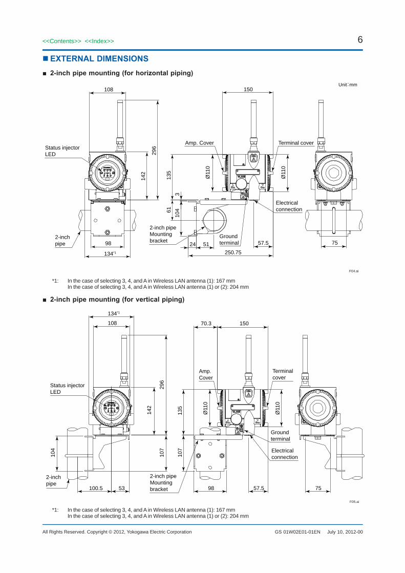
�EXTERNAL�DIMENSIONS■� 2-inch�pipe�mounting�(for�horizontal�piping)
Status injector LED
Amp. Cover
Electrical connection
Ground terminal
2-inch pipeMounting bracket2-inch
pipe
108 150Unit:mm
24 51 57.5 75
250.75134*1
98
142
296
135
Ø11
0
Ø11
0
310
461
F04.ai
Terminal cover
*1: In the case of selecting 3, 4, and A in Wireless LAN antenna (1): 167 mm In the case of selecting 3, 4, and A in Wireless LAN antenna (1) or (2): 204 mm
■� 2-inch�pipe�mounting�(for�vertical�piping)
Status injector LED
Amp. Cover
Terminal cover
Electrical connection
Ground terminal
2-inch pipeMounting bracket
2-inch pipe
100.5 53
134*1
108 70.3 150
98 7557.5
104
107
107
135
Ø11
0
Ø11
0
296
142
F05.ai
*1: In the case of selecting 3, 4, and A in Wireless LAN antenna (1): 167 mm In the case of selecting 3, 4, and A in Wireless LAN antenna (1) or (2): 204 mm

7<<Contents>> <<Index>>
All Rights Reserved. Copyright © 2012, Yokogawa Electric Corporation GS 01W02E01-01EN May 31, 2013-00
■� Antenna• Standard Antenna
(F9915KW)Directional: Non-directionalGain: 2 dBi
19
F06.ai
130 Ø14
Ø21
• High gain antenna (F9915KY)Directional: Non-directionalGain: 6 dBi
F07.ai
500
Ø26
Ø21.8
25
• High gain antenna (F9195VG)Directional: Non-directionalGain: 9 dBi
F08.ai
800
Ø26
Ø21.8
25
• Standard Antenna (F9195VA)Directional: Non-directionalGain: 2 dBi
117
Ø21
Ø16
F09.ai
19
■� Remote�antenna�cable• Cable 3 m
Antenna extension cableLength 3 m
F10.ai
• Cable 13 m
Antenna extension cable 2Length 10 m
Antenna extension cable 1Length 3 m
Arrestor
F11.ai

8
All Rights Reserved. Copyright © 2012, Yokogawa Electric Corporation
<<Contents>> <<Index>>
GS 01W02E01-01EN May 31, 2013-00
■� Antenna�mounting�bracket
18(0.69)
88 (3
.46)
135
(5.3
1)
292
(11.
50)
98 (3.86)
2-inch pipe (O.D. 60.5 mm)
72 (2.83)17(0.67)
F12.ai
68(2.68)
�INFRARED�CONFIGURATION
Infrared port
F13.ai
�TERMINAL�CONFIGURATIONS■�Communication�Interface:�1
100BASE-TXGround terminal
24 V DC +24 V DC −
Electrical connection
Communication connection
F14.ai
■�Communication�Interface:�2
Ground terminal
24 V DC +24 V DC −
100BASE-FX
Electrical connection
Communication connection
F15.ai
■�Communication�Interface:�5�*1
Ground terminal
24 V DC +24 V DC −
Electrical connection Blind plug
F16.ai
*1: Don’t use the 100 BASE-TX connection by RJ-45 connector.

9
All Rights Reserved. Copyright © 2012, Yokogawa Electric Corporation
<<Contents>> <<Index>>
GS 01W02E01-01EN
9<<Contents>> <<Index>>
Subject to change without notice.May 31, 2013-00
�ORDERING�INFORMATIONSpecify the following when ordering1. Model, suffix codes, and option codes2. Tag Number (if required) Specify Tag number (up to 16 letters) to be
engraved on the tag plate. The specified letters are written on TAG_Name (16 letters) in the memory.
�RELATED�PRODUCTS�GENERAL�SPECIFICATIONS
Field Wireless System Overview :Refer to GS 01W01A01-01EN
Field Wireless Management Station YFGW410: GS 01W02D01-01EN
Field Wireless Media Convertor YFGW610: GS 01W02D02-01EN
�TRADEMARKYFGW is a registered trademark of Yokogawa Electric Corporation. Other product and company names appearing in this document are trademarks or registered trademarks of their respective holders.


