

Graph Visualization and Navigation in Information Visualization: a Survey
Ivan Herman, Guy Melançon, and M. Scott Marshall
(Presentation: Anne DentonMarch 6, 2003)
Outline Graph drawing and graph
visualization Graph layout Navigation of large graphs Reorganization of data: Clustering

Information Visualizationvs. Graph Drawing Graph Drawing
Old topic, many books, etc. May have other goals than visualization
E.g. VLSI design Graph Visualization
Size key issue Usability requires nodes to be discernable Navigation considered

Node Information? Sometimes a “size” or “importance” is
represented Navigational systems may have links to
data Glyphs?
Mentioned as representation of higher levels in hierarchical clustering
Focus on structure-based properties Application independent

Examples Class browsers Entity relationship diagrams Real-time systems (state transition
diagrams) VLSI circuit design (circuit schematics
rather than actual design) Document management system
Web-navigation Virtual Reality (scene graph)

History of Graph Drawing Euler used a drawing to solve the
Königsberger Brückenproblem (1736) Symposia on Graph Drawing initiated
1992 Issues
Planarity No edges cross in 2D
Aesthetic rules Edges should have same length Edges should be straight lines Isomorphic substructures displayed equivalently

Note: Isomorphic subtrees laid out in same way
Problem: High Density of nodes
Reingold and Tilford algorithm for Trees

Tasks Related to Graph Drawing Layering a graph Turning graph into directed acyclic graph Planarizing (achieve that no edges cross) Minimizing area Minimizing number of bends in edgesBut Algorithms too complex for large graphs

Problem: Size Previous example: few hundred
nodes How about thousands of nodes? Solutions
3D Non-Euclidean geometry (e.g.,
hyperbolic geometry) Reduce size Show part only / blow up part
Other problems related to Navigation Predictability
Two different runs on similar trees should lead to similar results
Traditional layouts next page are predicatable
Time Complexity Real time interaction

Traditional Tree Layouts Classical layout on earlier slide H-tree layout: best for balanced
trees Radial view Balloon view: related to 3-d cone
tree

Tree-Map Useful for information visualization
because area is meaningful Example:
http://www.smartmoney.com/marketmap Size represents market share Color represents performance More information available through
clicking Problem: Tree structure less clear

Layout of Directed Graphs Layering (http://www.csus,yk,ue/staff/NikolaNikolov/#
phd)

Spring Layout Force directed Nodes are modeled as physical
bodies that are connected through springs (edges)
High time complexity: > O(N3) Not predictable

Spanning Trees Further conclusions from size
Don’t insist on planarity Don’t worry about edge crossings
Graph can be visualized through minimum spanning tree Additional edges added later Very common technique Helps with predictability Visualization depends on starting point

3D Techniques Benefits
“Gaining more space” Human familiarity with 3D
Problems 2D displays Missing motion and stereo cues May be solved by better technology

Examples of 3D Techniques 3D version of a radial tree Info cube

Cone Tree Developed directly for 3D Interactiveness important:
Nodes can be rotated

Fly-Through of 2D Representation SGI File System Navigator Size represents file size Similar:
Perspectivewall

Hyperbolic Layout Mainly used for trees E.g. web-content viewers 2D or 3D Similar to fish-eye lense Possibility of interacting with large
trees

EBI Hyperbolic Viewers 2D example appletshttp://industry.ebi.ac.uk/~alan/components/examples/example1.htmlhttp://www.inxight.com/map
3D image

Hyperbolic Viewer Concepts For a given point and non-intersecting line: many
parallel lines through point Segments that are congruent in the hyperbolic
sense are exponentially smaller in the Euclidean sense when approaching the perimeter
Projective Klein model Straight lines Suitable for 4x4 matrix-based graphics
Conformal or Poincaré model Straight lines drawn as arcs Angles are drawn correctly in Euclidean sense Computationally more demanding

Klein Model vs. Poincare ModelT. Munzner, P. Burchard, “Visualizing the structure of the
World Wide Web in 3D Hyperbolic Space,” Proceedings of the VRML Symposium, pp 33-38, 1995.
Klein Model Poincare Model

Simple Tree Construction Algorithm Node P with with wedge QPR Subtrees start at P1, P2, and P3
Euclidean Hyperbolic

Navigation and Interaction Zoom and pan
Zoom for graphs exact, not pixel-based (adjustment of screen transformations)
Geometric zooming Simple blow-up
Semantic zooming Content changes Clustering
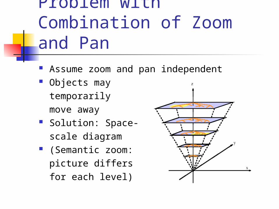
Problem with Combination of Zoom and Pan Assume zoom and pan independent Objects may
temporarily move away
Solution: Space-scale diagram
(Semantic zoom:picture differsfor each level)

Focus + Context Techniques Zooming looses contextual
information Focus + context keeps context Example
Fisheye distortion
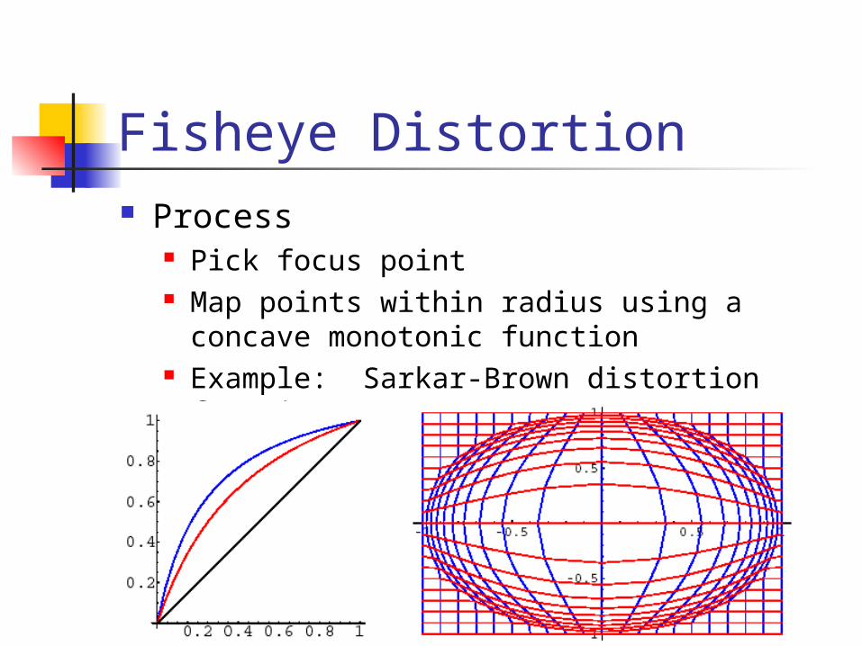
Fisheye Distortion Process
Pick focus point Map points within radius using a concave
monotonic function Example: Sarkar-Brown distortion function

Problem with Fisheye Distortion should also be applied to links
Prohibitively slow (polyline) Alternative
Continue using lines Can result in unintended line crossings
Other Alternative Combine layout with focus+context Hyperbolic viewer Other combinations possible (e.g. balloon view
with focus-dependent radii) but not yet done

Incremental Exploration and Navigation For very large graphs (e.g. Internet) Small portion displayed Other parts displayed as needed Displayed graph small Layout and interaction times may be smallExample not from the paperhttp://touchgraph.sourceforge.net/(Force-directed? Note how animation helps
adjusting to new layout)

Clustering Structure-based clustering
Most common in graph visualization Often retain structure of graph Useful for user orientation
Content-based clustering Application specific Can be used for
Filtering: de-emphasis or removal of elements from view
Search: emphasis of an element or group of elements

Clustering continued Common goal
Finding disjoint clusters Clumping
Finding overlapping clusters Common technique
Least number of edges between neighbors(Ratio Cut technique in VLSI design)

Hierarchical Clustering From successive application
of clustering process Can be navigated
as tree

Visualization of higher levels Herman et al. say
glyphs are used (?)
P. Eades, Q. Feng, “Multilevel Visualization of Clustered Graphs,” Lecture Notes in Computer Science”, 1190, pp 101-112, 1997

Node Metrics Measure abstract feature Give ranking Edge metrics also possible Structure-based or content-based Examples
Application-specific weight Degree of the node “Degree of Interest” (Furnas)

Methods of representing unselected nodes Ghosting
De-emphasizing or relegating nodes to background
Hiding Not displaying at all
Grouping Grouping under super
-node representation

Summary Graph drawing and graph visualization
Overlap but different goals and problems Graph layout
Much is known from graph drawing Navigation of large graphs
Key tool in dealing with size Reorganization of data: Clustering
Still much to be done


