

✫ Software implementations of rendering are slow.
� OpenGL on Sparc workstations.
✫ Performance can be improved using sophisti-
cated algorithms and faster machines.
✫ Real-time large-scale 3D graphics is not possi-
ble without hardware support.
✫ At least some of the rendering steps can be
replaced by hardware.
✫ Rendering is ideal for pipeline and multipro-
cessor architectures.
Graphics Architecture
CPS124, 296: Computer Graphics Graphics Hardware Page 1
Generation: Capabilities for which the architec-
ture was primarily designed.
First Generation
✫ First machines came out in early 1980s.
✫ Transformation capabilities.
✫ Limited frame-bu�er processing.
✫ Flat shading.
✫ Smooth shading, z-bu�er not supported.
✫ Examples:
� SGI Iris 3000 (1985);
� Apollo DN570(1985).
✫ Later machines: Limited smooth shading &
depth bu�ering.
� Examples: SGI 4DG (1986).
� E�ective for wire-frame images.
A Brief History
CPS124, 296: Computer Graphics Graphics Hardware Page 2

✫ Reduced memory costs &
Application-speci�c ICs (ASICs):
� Allowed large frame-bu�er with multiple ren-
dering processors.
✫ Interpolation of colors and depths.
✫ Memory capacity & bandwidth allowed depth
bu�ering.
✫ Examples:
� SGI GT (1988);
� Apollo DN590(1988).
✫ Later machines: limited texture mapping.
✫ Antialiasing of points and lines.
✫ Examples:
� SGI VGX;
� HP VRX;
� Apollo DN1000.
The Second Generation
CPS124, 296: Computer Graphics Graphics Hardware Page 3
SGI Reality Engine:
✫ Lighting, smooth shading, depth-bu�er, tex-
ture mapping, and antialiasing.
✫ 0:5 millions triangles per second, under assump-
tions:
� triangles in short strip.
� 10% triangles intersect the view frustum.
✫ Filtering for textures; large textures.
✫ Antialiasing for polygons.
✫ Pixel �ll rate: 30Hz rendering of 1280 � 1024
full-screen images.
SGI In�nite Reality:
✫ Pixel �ll rate 60Hz.
✫ Virtual texture memory.
✫ Display-list memory on graphics processor.
✫ Onyx and Onyx2 platforms.
The Third Generation
CPS124, 296: Computer Graphics Graphics Hardware Page 4

Standard Graphics Pipeline
Modeling transform
Trivialaccept/reject
TransformViewportMapping
Display traversal Lighting
View Clipping Rasterization
Monitor
GraphicsPipeline
CPS124,296:ComputerGraphics
GraphicsHardware
Page5
Assume polygons are being rendered.
✫ Application processing between frames.
✫ Geometry processing: 3D Polygons to 2D poly-
gons (in screen coordinates).
� Transformation from local to world coordi-
nates.
� Lighting at vertices.
� Transforming to a canonical view volume.
� Clipping.
� Perspective projection.
� Transformation to screen coordinates.
✫ Rasterization: 2D polygons ! pixels.
� Scan conversion.
� Shading.
� Hidden surface removal.
✫ Display processing: Converting pixels to ana-
log display.
Front end vs back end.
Graphics Pipeline
CPS124, 296: Computer Graphics Graphics Hardware Page 6

Geometry processing is ideal for pipelined process-
ing.
Stage 1 Stage 2 Stage 3
p3 p2 p1p3 p2p4
✫ Earlier stages process the next polygon while
later stages are processing the current polygon.
✫ Latency and throughput.
✫ SGI used pipelined processing in early archi-
tectures.
Pipelines Subsystems
CPS124, 296: Computer Graphics Graphics Hardware Page 7

Geometry processing faster on parallel machines.
✫ Polygons can be processed in parallel.
✫ Each processor performs all steps of geometry
processing on a polygon.
✫ Multiple polygons are processed simultaneously.
✫ Recent SGI systems use this approach.
Rasterization is ideal for parallel processing.
✫ 1280�1024 � 1:3Mpixels need to be processed
per frame.
✫ Supersampling: # subpixels � 10{20 million.
✫ Most pixels are processed multiple times in z-
bu�er algorithms.
✫ Use multiple processors.
Parallel Subsystems
CPS124, 296: Computer Graphics Graphics Hardware Page 8

1 1
1 1
1 1
1 1
2 2
2 2
2 2
2 23 43
3 3
3
3 3
3
4
4 4
4 4
4 4
Contiguous vs Interleaved
✫ Contiguous partitioning performs well in the
best case.
� Polygons are uniformly distributed.
� Each processor handles only a fraction of the
polygons.
� Load on each processor is balanced.
✫ Performs poorly in the worst case.
� All polygons are in a local region.
� A few processors do all the work.
✫ Interleaved is best in the worst case.
� Each processor handles all the polygons.
� Load is balanced.
Partitioning of Memory
CPS124, 296: Computer Graphics Graphics Hardware Page 9
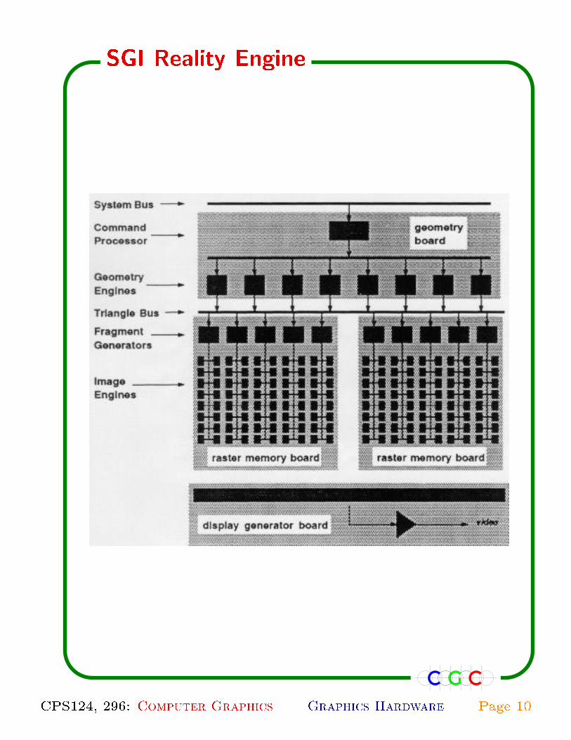
SGI Reality Engine
CPS124, 296: Computer Graphics Graphics Hardware Page 10

✫ Three, four, or six graphics boards.
✫ Geometry board:
� Input FIFO
� Command processor
� Geometry engines: 6; 8; or 12.
✫ Raster memory board: 1; 2, or 4.
� 5 fragment generators.
� Each with its texture memory.
� 80 image engines.
� Each image engine with frame bu�er mem-
ory: � 256 bits per pixel.
✫ Display board: Video functions.
� Video timing
� Color mapping
� D/A conversion
FIFO memories at
✫ Input and output of each geometry engine.
✫ Input of each fragment generator.
✫ Input of each image engine.
SGI Reality Engine
CPS124, 296: Computer Graphics Graphics Hardware Page 11
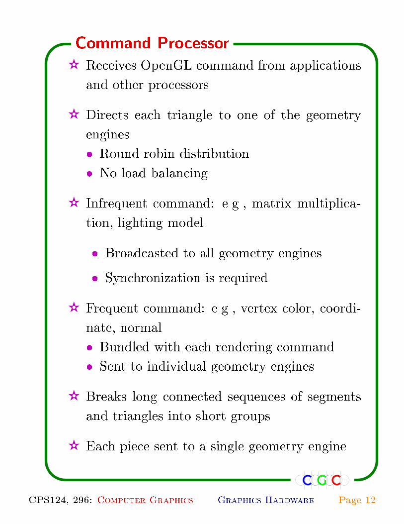
✫ Receives OpenGL command from applications
and other processors.
✫ Directs each triangle to one of the geometry
engines.
� Round-robin distribution.
� No load balancing.
✫ Infrequent command: e.g., matrix multiplica-
tion, lighting model.
� Broadcasted to all geometry engines.
� Synchronization is required.
✫ Frequent command: e.g., vertex color, coordi-
nate, normal.
� Bundled with each rendering command.
� Sent to individual geometry engines.
✫ Breaks long connected sequences of segments
and triangles into short groups.
✫ Each piece sent to a single geometry engine.
Command Processor
CPS124, 296: Computer Graphics Graphics Hardware Page 12
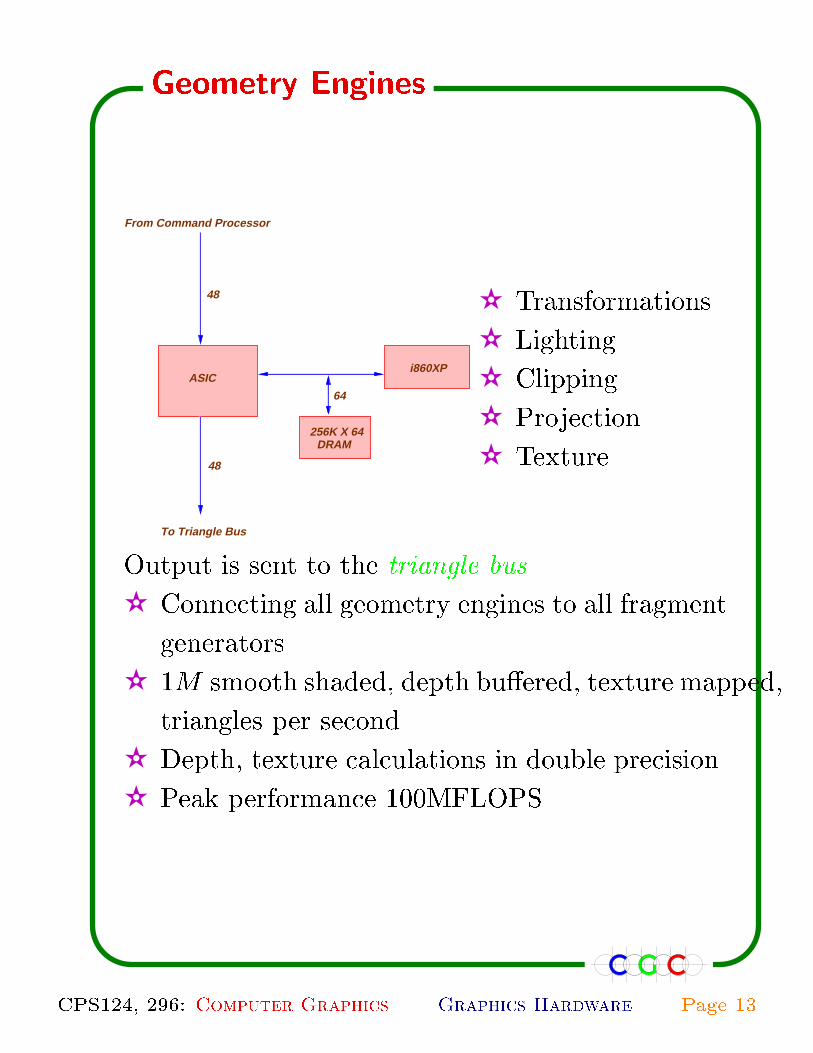
64
48
48
To Triangle Bus
From Command Processor
ASIC
DRAM256K X 64
i860XP
✫ Transformations
✫ Lighting
✫ Clipping
✫ Projection
✫ Texture
Output is sent to the triangle bus.
✫ Connecting all geometry engines to all fragment
generators.
✫ 1M smooth shaded, depth bu�ered, texture mapped,
triangles per second.
✫ Depth, texture calculations in double precision.
✫ Peak performance 100MFLOPS
Geometry Engines
CPS124, 296: Computer Graphics Graphics Hardware Page 13

To 16 Image Engines
ASIC
From Triangle Bus
48
16
1M X 16DRAM
ASIC
ASIC
ASIC
✫ Output of geometry engines is sent to 5, 10, or
20 fragment generators; say 20.
✫ Each fragment generator responsible for 1/20 of
the screen's pixels; 64K pixels.
✫ Interleaved partitioning of the screen.
✫ Computes the intersection of the set of pixels
fully or partially covered by the triangle.
✫ For each fragment it computes
� Depth, color (including texture)
� A subsample mask for each fragment.
✫ Output is sent to 16 image engines.
Fragment Generator
CPS124, 296: Computer Graphics Graphics Hardware Page 14
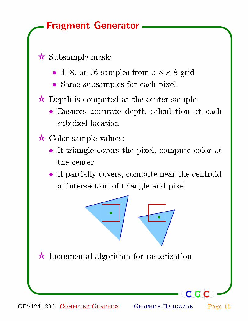
✫ Subsample mask:
� 4, 8, or 16 samples from a 8� 8 grid.
� Same subsamples for each pixel.
✫ Depth is computed at the center sample.
� Ensures accurate depth calculation at each
subpixel location.
✫ Color sample values:
� If triangle covers the pixel, compute color at
the center.
� If partially covers, compute near the centroid
of intersection of triangle and pixel.
✫ Incremental algorithm for rasterization.
Fragment Generator
CPS124, 296: Computer Graphics Graphics Hardware Page 15
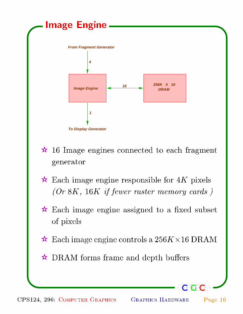
4
Image Engine
1
To Display Generator
256K X 16DRAM
From Fragment Generator
16
✫ 16 Image engines connected to each fragment
generator.
✫ Each image engine responsible for 4K pixels.
(Or 8K, 16K if fewer raster memory cards.)
✫ Each image engine assigned to a �xed subset
of pixels.
✫ Each image engine controls a 256K�16 DRAM.
✫ DRAM forms frame and depth bu�ers.
Image Engine
CPS124, 296: Computer Graphics Graphics Hardware Page 16
✫ Each pixel is assigned 1024 bits
(Or 512, 256 if fewer raster memory cards.)
✫ These bits store:
� Color (R, G,B, A values) for each subpixel
� 12bits each if 8 subsamples;
� 8 bits each if 16 subsamples.
� Depth:
� 32 bits if 8 subsamples
� 24 bits if 16 subsamples.
� 1; 2; 4 1280� 1024 displayable color bu�ers
� Displayable bu�ers have the same resolu-
tion as subsamples.
Image Engines
CPS124, 296: Computer Graphics Graphics Hardware Page 17
✫ When a triangle � is passed to a fragment gen-
erator, it's slope information is passed to image
engines.
✫ Using slope information, image engines com-
pute depth at each subpixel of 8� 8 grid.
✫ For each 1 in the mask, depth value is com-
pared with the value stored in the depth bu�er.
✫ If comparison succeeds
� Color and depth values in the framebu�er
are updated.
� Aggregate color value is recomputed.
� New color value is rewritten on the dis-
playable bu�er.
Image Engines
CPS124, 296: Computer Graphics Graphics Hardware Page 18
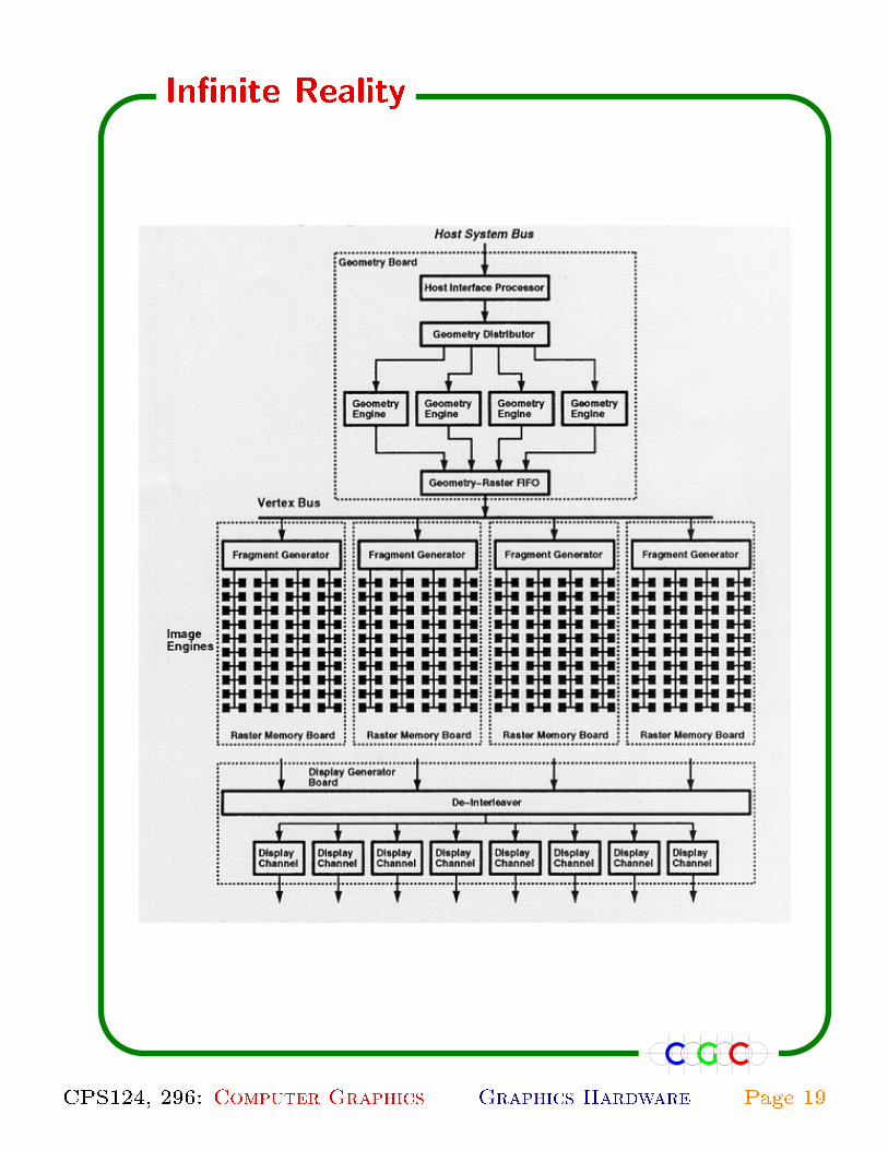
In�nite Reality
CPS124, 296: Computer Graphics Graphics Hardware Page 19

✫ Pixel �ll rate � 60 frames per second.
✫ Each pixel is assigned 0.5{2K bits.
✫ Speed up command processinng.
✫ Display lists trasferred from the host processor
using DMA transfer.
✫ 15MBmemory to store display lists at the graph-
ics processor.
✫ Customized geometry processors.
✫ Geometry distribution:
� Round robin: Simple assignment.
� Least busy: Better performance.
✫ Vertex bus instead of triangle bus.
� Triangle slope information is not passed.
� Only vertex information is passed.
� Reduces bandwidth by 60%.
� Load on vertex and input buses are similar.
✫ Additional hardware for texture mapping.
In�nite Reality
CPS124, 296: Computer Graphics Graphics Hardware Page 20

Pixel Plane 5
CPS124, 296: Computer Graphics Graphics Hardware Page 21
(Fuchs et al., 1989)
✫ Performance: � 2:3M triangles per second.
✫ Parallel geometry processing.
� 50 graphics processors
✫ Parallel rasterization.
� Contiguous partition.
� 20 renderes.
� separate shaders.
Pixel Plane 5
CPS124, 296: Computer Graphics Graphics Hardware Page 22
✫ Receives polygons from application or other
processors.
✫ Performs geometric processing.
✫ Assigns processed polygons to contiguous par-
titions.
� Each partition is 128� 128 square.
� Each graphics processor has a bin for every
partition.
✫ After all polygons are processed, all bins are
passed to renderers.
✫ Communication is through a high bandwidth
ring network.
Graphics Processor
CPS124, 296: Computer Graphics Graphics Hardware Page 23

All bins are processed in parallel
✫ A renderer rasterizes all polygons in one par-
tition's bin from each graphics processor.
✫ After processing these bins, renderee processes
bins of another partition.
Rasterization is performed using logic-enhanced mem-
ory.
✫ A small processor for each of the 128� 128 =
16K pixels.
✫ 2K memory for each pixel.
✫ Each processor maintains a few states, e.g., its
x- & y-coordinates, and evaluates
Ax+By + C +Dx2 +Exy + Fy2
Renderer
CPS124, 296: Computer Graphics Graphics Hardware Page 24

(Molnar et al., 1992)
Being developed by Hewlett-Packard.
✫ Unbounded parallelism in theory; MIMD ma-
chine.
✫ Performance: in theory: unlimited polygons
per second.
✫ Rendering is performed by n complete render-
ing systems.
� Each system includes a graphic processor,
renderer, and a shader.
� Each system processes 1=n polygons.
� It outputs the frame bu�er and also the z-
bu�er.
✫ Composites n di�erent images to produce the
overall image.
✫ Unlike other machines, one pixel may be pro-
cessed by many processors.
Pixel Flow
CPS124, 296: Computer Graphics Graphics Hardware Page 25


