

Catálogos Online
Distribuidor e revendedor autorizado.
(11) 4174-3300www.hmchydraulics.com.br

PARKER CALZONIRadial Piston Motor
Type MR, MRE
RCOe 1806/09.05

2RCOe 1806/03.05
The specified data are for product description purposes only and must not be interpreted as warranted characteristic in a
legal sense. All rights reserved. Subject to revision.
TABLE OF CONTENTS - MOTOR TYPE MR - MRE
CONTENTS PAG.
TABLE OF CONTENTS 2
GENERAL CHARACTERISTICS 3
FUNCTIONAL DESCRIPTION 4
TECHNICAL DATA 5
FLUID SELECTION 6
FLUSHING PROCEDURE 7
OPERATING DIAGRAM MOTOR TYPE MR 33 MR 57 MR 73 8
OPERATING DIAGRAM MOTOR TYPE MR 93 MR 110 MR 125 9
OPERATING DIAGRAM MOTOR TYPE MR 160 MR 190 MR 200 10
OPERATING DIAGRAM MOTOR TYPE MR 250 MR 300 MRE 330 11
OPERATING DIAGRAM MOTOR TYPE MR 350 MR 450 MRE 500 12
OPERATING DIAGRAM MOTOR TYPE MR 600 MR 700 MRE 800 13
OPERATING DIAGRAM MOTOR TYPE MR 1100 MRE 1400 MR 1600 14
OPERATING DIAGRAM MOTOR TYPE MR 1800 MRE 2100 MR 2400 15
OPERATING DIAGRAM MOTOR TYPE MR 2800 MRE 3100 MR 3600 16
OPERATING DIAGRAM MOTOR TYPE MR 4500 MRE 5400 MR 6500 17
OPERATING DIAGRAM MOTOR TYPE MR 7000 MRE 8200 18
OPERATING DIAGRAM (RUNNING PRESSURE DIFFERENCE AT NO LOAD) 19-20
OPERATING DIAGRAM (MOTOR /PUMP: BOOST PRESSURE) 20-21
RADIAL LOAD 22
BEARING LIFE 23
MOTOR DIMENSIONS 24-25
SHAFT END DIMENSIONS 26-27
COMPONENTS FOR SPEED CONTROL 28-29
PIPE CONNECTION FLANGES 30
COUPLINGS - KEY ADAPTERS 31
HOLDING BRAKE - UNIT DIMENSIONS - TECHNICAL DATA 32-33
INSTALLATION NOTES 34
ORDERING CODE 35
SALES AND SERVICE LOCATIONS WORLDWIDE 36

3RCOe 1806/03.05
The specified data are for product description purposes only and must not be interpreted as warranted characteristic in a
legal sense. All rights reserved. Subject to revision.
GENERAL CHARACTERISTICS - MOTOR TYPE MR - MRE
CONSTRUCTION
TYPE
MOUNTING
CONNECTION
MOUNTING POSITION
BEARING LIFE, RADIAL LOAD
DIRECTION OF ROTATION
FLUID
FLUID TEMPERATURE RANGE
VISCOSITY RANGE 1)
FLUID CLEANLINESS
Fixed displacement radial piston motor
MR ; MRE
Front flange mounting
Connection flange
Any (please note the installation notes on page 34)
See page 22 and 23
Clockwise, anti-clockwise - reversible
HLP mineral oils to DIN 51 524 part 2; Fluid type HFB, HFC and Bio-fluids on
enquiry. FPM seals are required with phosphorous acid-Ester (HFD)
t °C – 30° to + 80°
ν mm2/s 18 to 1000: Recommended operating range 30 to 50 (see fluid selection
on page 6)
Maximum permissible degree of contamination of fluid NAS 1638 Class 9. We
therefore recommend a filter with a minimum retention rate of ß10
> 75.
To ensure a long life we recommend class 8 to NAS 1638.
This can be achieved with a filter, with a minimum retention rate of ß5
>100.
A B
GENERAL CHARACTERISTICS
1) For different valves of viscosity please contact PARKER Calzoni

4RCOe 1806/03.05
The specified data are for product description purposes only and must not be interpreted as warranted characteristic in a
legal sense. All rights reserved. Subject to revision.
FUNCTIONAL DESCRIPTION - MOTOR TYPE MR - MRE
FUNCTIONAL DESCRIPTION The outstanding performance of this motor is the result of an original and patented design.
The principle is to transmit the effort from the stator to the rotating shaft (2) by means of
a pressurized column of oil (a) instead of the more common connecting rods, pistons, pads
and pins.
This oil column is contained by a telescopic cylinder (1) with a mechanical connection
at the lips at each end which seal against the spherical surfaces of the cylinder-heads (3)
and the spherical surface of the rotating shaft (4).
These lips retain their circular cross section when stressed by the pressure so there is no
alteration in the sealing geometry. The particular selection of materials and optimisation
of design has minimized both the friction and the leakage.
Another advantage of this design stems from the elimination of any connecting rods, the
cylinder can only expand and retract linearly so there are no transverse components of
the thrust. This means no oval wear on the moving parts and no side forces on the cylinder
joints.
A consequence of this novel design is a significant reduction in weight and overall size
compared with other motors of the same capacity.
TIMING SYSTEM The timing system is realized by means of a rotary valve (5) driven by the rotary valve
driving shaft (8) that it is connected to the rotating shaft.
The rotary valve rotates between the rotary valve plate (6) and the reaction ring (7)
which are fixed with the motor's housing. This timing system is also of a patented design
being pressure balanced and self compensating for thermal expansion.
EFFICIENCY The advantages of this type of valve coupled with a revolutionary cylinder arrangement
produce a motor with extremly high values of mechanical and volumetric efficiency.
The torque output is smooth even at very low speed and the motor gives a high perfor-
mance starting under load.
A B
2 1a 3
8 6 5 74

5RCOe 1806/03.05
The specified data are for product description purposes only and must not be interpreted as warranted characteristic in a
legal sense. All rights reserved. Subject to revision.
TECHINICAL DATA - MOTOR TYPE MR - MRE
eziS eziS eziS eziS eziSrotoMnoisrev
-ecalpsiD -ecalpsiD -ecalpsiD -ecalpsiD -ecalpsiDtnem
tnemoM tnemoM tnemoM tnemoM tnemoMfoaitreni
gnitatorstrap
-eroehT -eroehT -eroehT -eroehT -eroehTlacit
cificepseuqrot
.niM .niM .niM .niM .niM.tratseuqrot
/-eroehT
laciteuqrot
erusserPmumixaM erusserPmumixaM erusserPmumixaM erusserPmumixaM erusserPmumixaM egnardeepS egnardeepS egnardeepS egnardeepS egnardeepS mumixaM mumixaM mumixaM mumixaM mumixaMtuptuorewop
thgieW thgieW thgieW thgieW thgieW
tupni gnihsulf gnihsulf
.tnoc .tni kaep *B+A niarD tuohtiw htiw tuohtiw htiw
V J % p p p p p n n P P m
mc 3 mcgk 2 rab/mN rab rab rab rab rab mpr mpr Wk Wk gk
MMMMMR
3333333333 1,23 23,4 05,0 09 052 003 024 004 5
51(
rab
htiw
"1F"
tfahs
)laes
0041-1 0041-1 6,6 01 03
7575757575 4,65 67,4 09,0 09 0031-1 0031-1 11 71 03
3737373737 6,27 30,41 02,1 09 0021-1 0021-1 51 02 83
3939393939 6,29 11,51 05,1 09 0511-1 0511-1 71 52 83
011 011 011 011 011 0,901 91,61 07,1 09 0011-1 0011-1 81 82 83
521 521 521 521 521 7,421 88,65 00,2 09 009-1 009-1 71 52 64
061 061 061 061 061 7,951 05,75 45,2 09 009-1 009-1 02 03 64
091 091 091 091 091 6,191 02,85 50,3 09 058-1 058-1 42 63 64
002 002 002 002 002 2,991 51,75 02,3 09 008-1 008-1 52 83 05
052 052 052 052 052 9,052 08,06 00,4 09 008-1 008-1 23 84 05
003 003 003 003 003 1,403 34,56 08,4 09 057-1 057-1 53 35 05
053 053 053 053 053 5,943 09,522 75,5 09 046-1 046-1 14 26 77
054 054 054 054 054 6,154 08,922 02,7 09 006-1 006-1 64 57 77
006 006 006 006 006 9,706 70,562 07,9 09 025-1 025-1 65 48 79
007 007 007 007 007 9,607 04,853 03,11 09 005-1 005-1 56 79 79
0011 0011 0011 0011 0011 8,5211 05,154 09,71 09 033-5,0 033-5,0 77 911 041
0061 0061 0061 0061 0061 4,8951 34,666 04,52 09 062-5,0 062-5,0 69 441 902
0081 0081 0081 0081 0081 6,9081 01,458 08,82 09 052-5,0 052-5,0 301 351 902
0042 0042 0042 0042 0042 0,3932 04,5382 01,83 09 022-5,0 022-5,0 021 381 223
0082 0082 0082 0082 0082 0,2972 07,5792 05,44 09 512-5,0 512-5,0 721 491 223
0063 0063 0063 0063 0063 8,6363 04,1584 09,75 09 051-5,0 081-5,0 321 581 505
0054 0054 0054 0054 0054 7,2054 01,5105 07,17 19 031-5,0 071-5,0 041 012 505
0056 0056 0056 0056 0056 5,0646 6,67311 75,301 19 011-5,0 031-5,0 561 042 797
0007 0007 0007 0007 0007 2,7696 6,67311 93,111 19 001-5,0 031-5,0 071 052 797
MMMMMRE
033 033 033 033 033 4,233 05,56 03,5 09 012 052 053 004 5
51(
rab
htiw
"1F"
tfahs
)laes
057-1 057-1 23 94 05
005 005 005 005 005 9,794 08,922 39,7 09 006-1 006-1 64 07 77
008 008 008 008 008 2,408 04,853 18,21 09 054-1 054-1 56 39 79
0041 0041 0041 0041 0041 5,9631 05,154 08,12 29 082-5,0 082-5,0 77 201 541
0012 0012 0012 0012 0012 2,1902 01,458 03,33 19 052-5,0 052-5,0 001 841 122
0013 0013 0013 0013 0013 7,3013 07,5792 04,94 19 512-5,0 512-5,0 521 091 623
0045 0045 0045 0045 0045 2,1045 01,5105 10,68 29 021-5,0 061-5,0 041 012 905
0028 0028 0028 0028 0028 4,6228 6,67311 09,031 29 09-5,0 021-5,0 071 052 708
EHTNIELBALIAVAERASTNEMECALPSIDREGRAL EHTNIELBALIAVAERASTNEMECALPSIDREGRAL EHTNIELBALIAVAERASTNEMECALPSIDREGRAL EHTNIELBALIAVAERASTNEMECALPSIDREGRAL EHTNIELBALIAVAERASTNEMECALPSIDREGRAL FTRM-ETRM-TRM FTRM-ETRM-TRM FTRM-ETRM-TRM FTRM-ETRM-TRM FTRM-ETRM-TRM SEIRESROTOM SEIRESROTOM SEIRESROTOM SEIRESROTOM SEIRESROTOM
(*) Please consult PARKER Calzoni

6RCOe 1806/03.05
The specified data are for product description purposes only and must not be interpreted as warranted characteristic in a
legal sense. All rights reserved. Subject to revision.
FLUID SELECTION - MOTOR TYPE MR - MRE
EXAMPLE: At a certain ambient
temperature, the operating temperature in the
circuit is 50°C. In the optimum operating
viscosity range (vrec
; shaded section), this
corresponds to viscosity grades VG 46 or VG
68; VG 68 should be selected.
IMPORTANT: The drain oil temperature
is influenced by pressure and speed and is
usually higher than the circuit temperature or
the tank temperature. At no point in the
system, however, may the temperature be
higher than 80°C.
If the optimum conditions cannot be met due
to the extreme operating parameters or high
ambient temperature, we always recommend
flushing the motor case in order to operate
within the viscosity limits.
Should it be absolutely necessary to use a
viscosity beyond the recommended range,
you should first contact PARKER Calzoni
for confirmation.
GENERAL NOTES More detailed information regarding the choice of the fluid can be requested to PARKER Calzoni.Further notes on installation and commissioning can be found on page 34 of this data sheet. Whenoperating with HF pressure fluids or bio-degradable pressure fluids possible limitations of thetechnical data must be taken into consideration, please see information sheet TCS 85, or consult
PARKER Calzoni.
OPERATING VISCOSITY RANGE The viscosity, quality and cleanliness of operating fluids are decisive factors in determining thereliability, performance and life-time of an hydraulic component. The maximum life-time and perfor-mance are achieved within the recommended viscosity range. For applications that go beyond this
range, we recommend to contact PARKER Calzoni.
νrec.
= recommended operating viscosity 30...50 mm2/s
This viscosity refers to the temperature of the fluid entering the motor, and at the same time to thetemperature inside the motor housing (case temperature). We recommend to select the viscosity ofthe fluid based on the maximum operating temperature, to remain within the recommended viscosityrange. To reach the value of maximum continuous power the operating viscosity should be within therecommended viscosity range of 30 - 50 cSt.
LIMITS OF VISCOSITY RANGE For limit conditions the following is valid:
νmin.abs.
= 10 mm2/s in emergency, short term
νmin .
= 18 mm2/s for continuous operation at reduced performances
νmax.
= 1000 mm2/s short term upon cold start
CHOOSING THE TYPE OF FLUID The operating temperature of the motor is defined as the greater temperature between that of theACCORDING TO THE OPERATING incoming fluid and that of the fluid inside the motor housing (case temperature).WeTEMPERATURE recommend that you choose the viscosity of the fluid based on the maximum operating temperature,
to remain within the recommended viscosity range (see diagram). We recommend that the higherviscosity grade must be selected in each case.
FILTRATION The motor life also depends on the fluid filtration. At least it must correspond to one of thefollowing cleanliness. class 9 according to NAS 1638
class 6 according to SAE, ASTM, AIA
class 18/15 according to ISO/DIS 4406
In order to assure a longer life a cleanliness class 8 to NAS 1638 is recommended, achievedwith a filter of β
5=100. In case the above mentioned classes can not be achieved, please consult us.
CASE DRAIN PRESSURE The lower the speed and the case drain pressure, the longer the life of the shaft seal. The maximumpermissible housing pressure is
pmax
= 5 bar
If the case drain pressure is higher than 5 bar it is possible to use a special 15 bar shaft seal(see page 35, Seals, Code"F1").
"FPM" SEALS In case of operating conditions with high oil temperature or high ambient temperature, werecommend to use "FPM" seals (see page 35, Seals, Code "V1"). These "FPM" seals should be usedwith HFD fluids.
Temperature t in °C
Oil temperature range
vis
co
sity
ν (m
m2/s
)
νR
EC

7RCOe 1806/03.05
The specified data are for product description purposes only and must not be interpreted as warranted characteristic in a
legal sense. All rights reserved. Subject to revision.
FLUSHING PROCEDURE - MOTOR TYPE MR - MRE
FLUSHING CIRCUIT
(MONO-DIRECTIONAL ROTATION)
FLUSHING CIRCUIT
(BI-DIRECTIONAL ROTATION)
FLUSHING The motor case must be flushed when the continuous operating performances of the
motor are inside the "Continuous operating area with flushing" (see Operating Diagram
from page 8 to page 18), in order to assure the minimum oil viscosity inside the motor case
of 30 mm2/s (see page 6 - Fluid Selection). The flushing can be necessary also when the
operating performances are outside the "Continuous operating area with flushing", but the
system is not able to assure the minimum viscosity conditions requested by the motor as
specified at page 6.
NOTE1: The oil temperature inside the motor case is obtainable by adding 3°C to the motor surface
temperature (tA , see figures).
NOTE2: With the standard shaft seal the maximum drain case pressure is 5 bar. For the selection
of the restrictor, please consult us.
FLOW
EPYT NOISREVROTOMGNIHSULF
WOLF
RM 011,39,37,75,33 nim/l5=Q
ERM-RM 033,003,052,002,091,061,521 nim/l6=Q
ERM-RM 005,054,053 nim/l8=Q
ERM-RM 0041,0011,008,007,006 nim/l01=Q
ERM-RM 0012,0081,0061 nim/l51=Q
ERM-RM,0045,0054,0063,0013,0082,0042
0028,0007,0056nim/l02=Q
1) Please consult us.
1)“VFC” Flushing valve.
Restrictor
Restrictor

8RCOe 1806/03.05
The specified data are for product description purposes only and must not be interpreted as warranted characteristic in a
legal sense. All rights reserved. Subject to revision.
OPERATING DIAGRAM - MOTOR TYPE MR - MRE
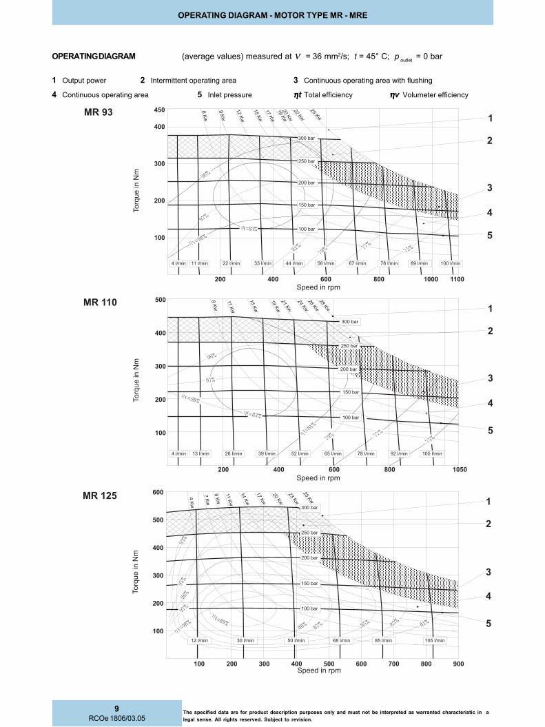
1 Output power 2 Intermittent operating area 3 Continuous operating area with flushing
4 Continuous operating area 5 Inlet pressure ηηηηηt Total efficiency ηηηηηv Volumeter efficiency
OPERATING DIAGRAM (average values) measured at ν = 36 mm2/s; t = 45° C; p outlet
= 0 bar
����
���
���
���������
�����
��� ��
�
�����
��� ��
������
���
���
���������������� ������ ������ ������ ������ ������ ������������
����� ��
�
���
��
��� ���� �� �
��
��
�������
�������
�������
�������
�����
����������
�����
�����
����
�����
����
�������
�
�
��
��
��
��
� �
���
��
�� �� ��� ��� ���� ��� ����
����
���
���
���������
��� �
��
�
�����
��� ���
���
� �
�����
���
���
����� ������ ������������������ ������ ������ ������������
�������
�������
�������
�������
����������
�
����
����
�����
�����
����
�����
�����
�
�
����
���
���
���������
�����
�����
����������������� ����� ����� ������ ������ ������������ ������ ������
����
���
����
� �
�������
�������
���
���
�������
�������
�������
���
���
���
���
���
���
� ���
���
��
��
�
�� �� � �� ��� ����� ��� ������
��
��
�
��
��
�
�
�
�
9RCOe 1806/03.05
The specified data are for product description purposes only and must not be interpreted as warranted characteristic in a
legal sense. All rights reserved. Subject to revision.
OPERATING DIAGRAM - MOTOR TYPE MR - MRE
1 Output power 2 Intermittent operating area 3 Continuous operating area with flushing
4 Continuous operating area 5 Inlet pressure ηηηηηt Total efficiency ηηηηηv Volumeter efficiency
OPERATING DIAGRAM (average values) measured at ν = 36 mm2/s; t = 45° C; p outlet
= 0 bar
�
�
����
����
���
���
���������
����
����
����
�����
�����
�����
�����
�����
�����
�������� ��� ����� �
�
���
�����
��
���
��
������������ ������ ������ �������������
���
��� �� ����� ��
��
���
��
��
���
������ ��� ���
�������
�������
�������
�������
�������
�
�
����
���
���
���������
������
�����
������
������
��
������
���
���
�����������
���
��
������
��
������
��
������
���
��
��
���
������
���
������ ������
�� �
�������
�����
�����
����
�����
�����
�������
�������
�������
���������������
�������
�������
�
�
����
���
���
���������
�����
�����
���
�����
���
������
���
���
����������� ������ ������ ������ ������������ ������ �������������
��
��
���
���
��
�
�� ��� ��� ��������
������������
�������
�������
�������
�������
����
����
�����
�����
�����
�����
�����
�����
�
�

10RCOe 1806/03.05
The specified data are for product description purposes only and must not be interpreted as warranted characteristic in a
legal sense. All rights reserved. Subject to revision.
OPERATING DIAGRAM - MOTOR TYPE MR - MRE
1 Output power 2 Intermittent operating area 3 Continuous operating area with flushing
4 Continuous operating area 5 Inlet pressure ηηηηηt Total efficiency ηηηηηv Volumeter efficiency
OPERATING DIAGRAM (average values) measured at ν = 36 mm2/s; t = 45° C; p outlet
= 0 bar
�
����
���
���
���������
�����
�����
����
�����
�����
�����
����������
�����
��
����
��
�
���
���
� �
��
���
�����
�����
����
���
�
������������������������� ������������������� ������ �������������� �������
���
���
��
��
��
��� ��
���
���
���
���
����
����� �� ��� ��� ���
�������
�������
�������
�������
�������
�
�
������
����
���
���
�����
�����
�����
�����
�����
�����
�����
����
�
�
����� ������ ������ ������ ������ ������ ������ �������������� ������� �������
�������
�������
�������
�������
�������
������
������������ �� ��� �� �� ��� ��� ���
���
���
���
���
��
��
���
��
���
� �
������
����
����
�����
�����
�����
�����
����������
����
���
���
�������
�������
�������
�������
������
�������
����� ������ ������ ������ ������ ������ ������ ��������������
������������ �� ��� �� �� ��� ��� ���
���
���
���
��
��
���
��
���
���
�
�

11RCOe 1806/03.05
The specified data are for product description purposes only and must not be interpreted as warranted characteristic in a
legal sense. All rights reserved. Subject to revision.
1 Output power 2 Intermittent operating area 3 Continuous operating area with flushing
4 Continuous operating area 5 Inlet pressure ηηηηηt Total efficiency ηηηηηv Volumeter efficiency
OPERATING DIAGRAM (average values) measured at ν = 36 mm2/s; t = 45° C; p outlet
= 0 bar
OPERATING DIAGRAM - MOTOR TYPE MR - MRE
������
����
�����
�����
�����
�����
�����
�����
�����
�����
�����
������ ������ ������������ ������� ������� ������� ������� ������� ������� �������
�
�
����
���
���
���������
�������
�������
�������
�������
�������
������
��� �� ��� �� �� ��� ��� � �
���
���
����
���
���
��
��
�����
����
����
�����
�����
�����
�����
�����
�����
���������� ������ ������ ������ ������ �������
�������
�������
�������
�������
�������
������
����
���
���
��� ����
����
���
���
��
��
���������
������� ���������������������
��� �� ��� �� �� ��� ���
�
�
���
����
���
���
���������
������� �����
�����
�����
�����
�����
�����
�����
���
�����
���
�
���
���
���
������
����
����
������ ������ ������� ������� ���������������������
��
��� �� ��� �� �� ��� ���
���
��
���
���
����
���
������
�������
�������
�������
�������
�
�

12RCOe 1806/03.05
The specified data are for product description purposes only and must not be interpreted as warranted characteristic in a
legal sense. All rights reserved. Subject to revision.
OPERATING DIAGRAM - MOTOR TYPE MR - MRE
1 Output power 2 Intermittent operating area 3 Continuous operating area with flushing
4 Continuous operating area 5 Inlet pressure ηηηηηt Total efficiency ηηηηηv Volumeter efficiency
OPERATING DIAGRAM (average values) measured at ν = 36 mm2/s; t = 45° C; p outlet
= 0 bar
�
�
���� ��
����
���
���
�������
������� ������� ������� ������������� ��������������
����
�����
�����
�����
�����
�����
�����
�����
�����
�����
�������
�������
�������
������
������������ ������
��� �� ��� �� �� ���
���
����
����
���
���
����
���
���
��
��
���������
�����
�����
�����
�����
�����
�����
�����
�����
�����
������ ������������ ������ ������� ����������������������������
�
�
����
���
���
���������
�������
�������
�������
�������
�������
������
��
���
����
����
���
���
����
���
���
��
��
��� �� ��� �� �� ���
��� �
����
�����
�����
�����
�����
�����
�����
�����
�����
�����
������ ������ ������ ������ ������� ������� ������� ������� �������
�
�
����
���
���
���������
�������
�������
�������
�������
�������
������
���� �
��� �� ��� �� �� ���
��
��
���
���
����
���
���
����
����
��

13RCOe 1806/03.05
The specified data are for product description purposes only and must not be interpreted as warranted characteristic in a
legal sense. All rights reserved. Subject to revision.
OPERATING DIAGRAM - MOTOR TYPE MR - MRE
1 Output power 2 Intermittent operating area 3 Continuous operating area with flushing
4 Continuous operating area 5 Inlet pressure ηηηηηt Total efficiency ηηηηηv Volumeter efficiency
OPERATING DIAGRAM (average values) measured at ν = 36 mm2/s; t = 45° C; p outlet
= 0 bar
�
�
�������
����
���
���
�����
�����
�����
�����
�����
����������
������������ ������� �������������� ������� ���������������������
� ��� � � �� � ��� � � �� �
���
���
���
���
� ��
����
���
��
���
����
����
�������
�������
�������
�������
������
���������
�����
�����������
����
�����
�����
�����
�����
�����
�����
�����
�����
�����
����
���
���
���������
�������
�������
�������
�������
������
�������
� ��� � � �� � ��� � � �� � ��
����
���
��
���
����
� ��
���
���
���
���
����
�
�
�������������� ������� ������� ������� ������������� ������ ������
������
�����
�����
�����
�����
�����
�����
�����
�����
�����
� ��� � � �� � ��� � � �� �
�
�
����
���
���
���������
�������
�������
�������
�������
������
�������
����
���
��
���
����
� ��
���
���
���
���
�������������� ������� ������� ������� ������� ������������� ������ ������
�
14RCOe 1806/03.05
The specified data are for product description purposes only and must not be interpreted as warranted characteristic in a
legal sense. All rights reserved. Subject to revision.
OPERATING DIAGRAM - MOTOR TYPE MR - MRE
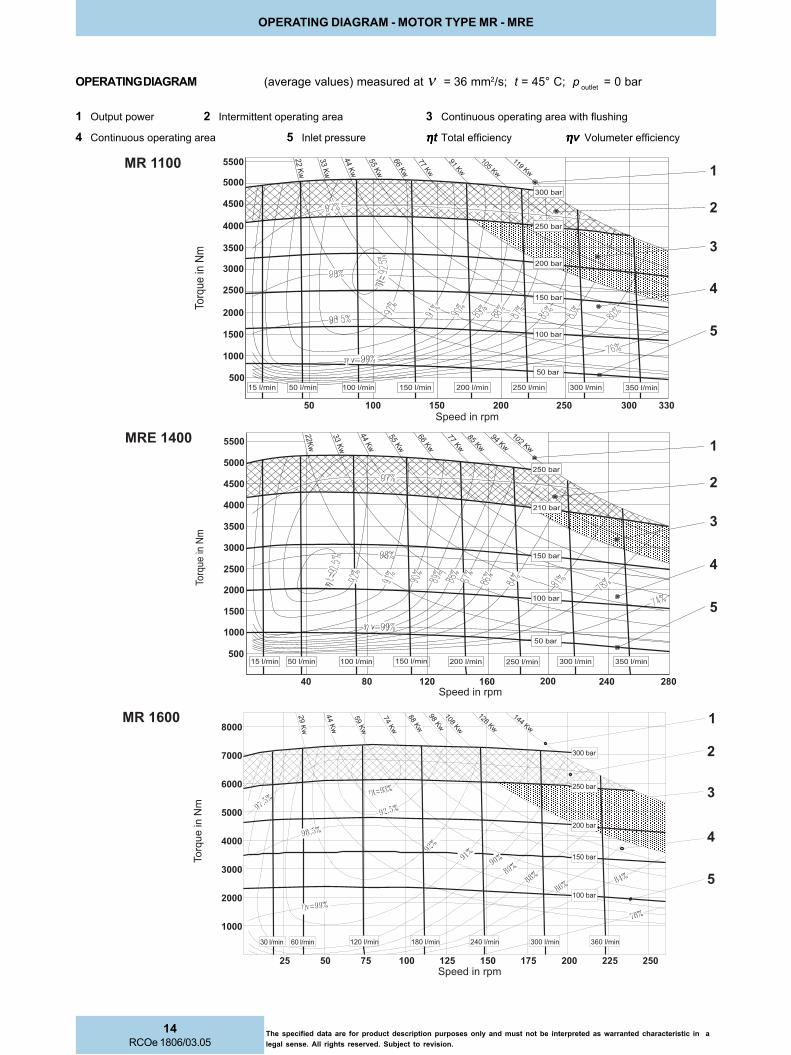
1 Output power 2 Intermittent operating area 3 Continuous operating area with flushing
4 Continuous operating area 5 Inlet pressure ηηηηηt Total efficiency ηηηηηv Volumeter efficiency
OPERATING DIAGRAM (average values) measured at ν = 36 mm2/s; t = 45° C; p outlet
= 0 bar
����
���
���
���������
������� �����
�����
�����
�����
�����
������
�����
������
������
�����
�
���
���
� �
������
���
����
����
�
������
����
����
� � ��� �
����
���
����
���
�� � � �� �
����
���
����
����
������������� ������������� �������
�������
������� �������
�������
�������
�������
������� �
�
� �� �� ��� �� � ��
��
����
� ��
���
��
����
� ��
���
��
���
�� �
�
�������
����
���
���
���������
����
�����
�����
�����
�����
����������
�����������
������������ ������� ������� �������������� ������� �������
�������
�������
�������
�������
������
�
�
�����
�����
�����
�����
�����
�����
�����
������
������
�������
�������
�������
������
����
���
���
���������
��
����
� ��
���
��
����
� ��
���
��
���
��
� ��� � � �� � ��� ���
�������
�������
�������
�������������� ������� ������� ������� �������������������

15RCOe 1806/03.05
The specified data are for product description purposes only and must not be interpreted as warranted characteristic in a
legal sense. All rights reserved. Subject to revision.
OPERATING DIAGRAM - MOTOR TYPE MR - MRE
1 Output power 2 Intermittent operating area 3 Continuous operating area with flushing
4 Continuous operating area 5 Inlet pressure ηηηηηt Total efficiency ηηηηηv Volumeter efficiency
OPERATING DIAGRAM (average values) measured at ν = 36 mm2/s; t = 45° C; p outlet
= 0 bar
�����
�����
�����
�����
�����
������
������
������
������
������
������ ������
� � �� �� ��� �� �� ��� ��� �� �
�����
�����
����
����
����
����
���
���
����
���
����
�
�
����
����
��
�
���������
�������
�������
�������
�������
�������
������
�������������� ������� ������� ������� �������
������� �����
�����
�����
�����
�����
������
������
������
������
������� ������� ��������������
� � ��� � � � �� �� �
����
����
����
����
����
���
���
����
���
����
���
���
�
�
���������
�������
�������
�������
�������
�������
������
������ ������ ������� �������
�
�
�������
����
���
���
���������
������
������
�����
�����
�����
�����
������
������
������ ������ ������� �������������� ������� ���������������������
�������
�������
������
�������
�������
� � ��� � � � �� �� �
����
���
����
���
���
����
����
����

16RCOe 1806/03.05
The specified data are for product description purposes only and must not be interpreted as warranted characteristic in a
legal sense. All rights reserved. Subject to revision.
1 Output power 2 Intermittent operating area 3 Continuous operating area with flushing
4 Continuous operating area 5 Inlet pressure ηηηηηt Total efficiency ηηηηηv Volumeter efficiency
OPERATING DIAGRAM (average values) measured at ν = 36 mm2/s; t = 45° C; p outlet
= 0 bar
�
�
�������
�����
�����
�����
������
������
������
������
������� ������� ������� �������
� �� �� � �� �� �� �� � � �� ���
����
���
���
���������
�������
�������
�������
�������
������
������ ��������������
�������
������
���
���
����
����
�����
����
����
�����
�����
� � �� �� ��� �� �� ��� ��� �� �
����
���
���
��������
���������
�������
�
�
�����
�����
�����
�����
������
������
������
������
������
�������
�������
������
�������
�������
�������������� ������� �������������������� ����������
���
����
���
���
����
����
����
����
�����
�����
����
�����
����
���
����
���
���
����
����
����
����
�����
�����
����
�����
� � �� �� ��� �� �� ��� ��� �� �
������
�����
�����
�����
�����
������
������
������
������
������
����
���
���
���������
�������
�������
�������
�������
�������
������
�
�
������ ������ ������� ������� ������� ������� ������� �������
OPERATING DIAGRAM - MOTOR TYPE MR - MRE

17RCOe 1806/03.05
The specified data are for product description purposes only and must not be interpreted as warranted characteristic in a
legal sense. All rights reserved. Subject to revision.
1 Output power 2 Intermittent operating area 3 Continuous operating area with flushing
4 Continuous operating area 5 Inlet pressure ηηηηηt Total efficiency ηηηηηv Volumeter efficiency
OPERATING DIAGRAM (average values) measured at ν = 36 mm2/s; t = 45° C; p outlet
= 0 bar
����
����
����
����
� ���
�����
����
���
����
�����
�����
�� � �� � � �� �� �� �� ��� ��� �� ���
�
�
�����
�����
�����
������
������
������
������
������
����
���
���
���������
�������
�������
�������
�������
�������
������
�������������
���� ��
�������������� ������� ������� ������� ��������������
������
�
�
���� ��
����
���
���
���������
������ ������� ������� �������������� ����������������������������
�����
�����
�����
������
������
������
������
������
�������
�������
������
�������
�������
� � �� �� ��� �� �� ���
���
���
����
����
�����
����
����
�����
�����
����
���
������
���
���
����
����
�����
����
����
�����
�����
����
���
�� �� � �� �� ��� ��� � � ���
�
�
�����
�����
�����
������
������
������
������
������
������
����
���
���
���������
�������
�������
�������
�������
�������
������
��� ��
�������������� ������� ������� ������� ������������� �������
OPERATING DIAGRAM - MOTOR TYPE MR - MRE

18RCOe 1806/03.05
The specified data are for product description purposes only and must not be interpreted as warranted characteristic in a
legal sense. All rights reserved. Subject to revision.
OPERATING DIAGRAM - MOTOR TYPE MR - MRE
1 Output power 2 Intermittent operating area 3 Continuous operating area with flushing
4 Continuous operating area 5 Inlet pressure ηηηηηt Total efficiency ηηηηηv Volumeter efficiency
OPERATING DIAGRAM (average values) measured at ν = 36 mm2/s; t = 45° C; p outlet
= 0 bar
����
����
����
����
� ���
�����
����
���
����
�����
������
�
�������
����
���
���
���������
�����
�����
�����
������
������
������
������
������
������
�������
�������
������
�������
�������
������ ������� ������� �������������� ���������������������������� �������
�� � �� � �� �� �� �� ��� ��� �� �
�
�
�������
����
���
���
�����
�����
�����
������
������
������
������
�������
�������
�������
�������
������
������������� ������� ������� ������� ������� ������� ��������������
�� � �� � � �� �� �� �� ��� ��� �� ���
�����
�����
����
���
����
�����
� ���
����
����
����
����
���������������
������
�������

19RCOe 1806/03.05
The specified data are for product description purposes only and must not be interpreted as warranted characteristic in a
legal sense. All rights reserved. Subject to revision.
OPERATING DIAGRAM - MOTOR TYPE MR - MRE
OPERATING DIAGRAM (average values) measured at ν = 36 mm2/s; t = 45° C; p outlet
= 0 bar
Min. required pressure difference ΔΔΔΔΔp with idling speed (shaft unloaded)
MR33 - 110
MR - MRE350 - 800
MR - MRE125 - 330
MR - MRE1100 - 2100
��
�
�
�
�
�
�� �� ������ ���� ��� ���
���
!!���
����
��
����
���������
"#����
"#���
"#���
"#���
"#���
�
�
��
�
�
�
��
� � ���� �� ������ � ��� � �� � � ��
���
!!�
����
���
���
��
���������
"#����"#����
"#$����
"#����
"#����"#$���
�
�
�
�
��
��
�
�
����� ��� ���� ������ ��� ��� ���������
���
!!�
����
���
���
��
"#���"#����"#����
"#����
"#���
"#$��
��
"#����
�
�
�
��
�
���
!!�
����
���
���
��
���������������� �� �� � � ��� �� � �� ���
"#��
���"#$��
���
"#�����
"#$��
���
"#����
�

20RCOe 1806/03.05
The specified data are for product description purposes only and must not be interpreted as warranted characteristic in a
legal sense. All rights reserved. Subject to revision.
Minimum boost pressure during pump operation
OPERATING DIAGRAM - MOTOR TYPE MR - MRE
OPERATING DIAGRAM (average values) measured at ν = 36 mm2/s; t = 45° C; p outlet
= 0 bar
Min. required pressure difference ΔΔΔΔΔp with idling speed (shaft unloaded)
MR - MRE2400 - 8200
MR33 - 110
MR - MRE125 - 330
��
�
�
�
�
��
�
�� �� ������ ���� ��� ��� ���������
"
����
!%��
��!!
����
��
��
"#����
"#���
"#���
"#���
"#���
�
�
��
�
��
�
�
����� ��� ���� ��� ������ � ���� ���������
"
����
!%��
��!!
����
��
��
"#����
"#����
"#����
"#����
"#����
"#$��
��
"#����
�
��
�
�
�
��
�
���� ��������� �������� �
���
!!�
����
���
���
��
���������
"#$�����"#��
���
"#�����
"#$
����
�
"#�����
"#�����
"#$�����
"#�����"#�����

21RCOe 1806/03.05
The specified data are for product description purposes only and must not be interpreted as warranted characteristic in a
legal sense. All rights reserved. Subject to revision.
OPERATING DIAGRAM - MOTOR TYPE MR - MRE
OPERATING DIAGRAM (average values) measured at ν = 36 mm2/s; t = 45° C; p outlet
= 0 bar
Minimum boost pressure during pump operation
MR - MRE350 - 800
MR - MRE1100 - 2100
MR - MRE2400 - 8200
��
�
�
�
�
�
��
����� �� ��� �� �� ���� � � � � � � � ���������
"
����
!%��
��!!
����
��
�� "#����
"#$����
"#����
"#����"#����
"#$����
��
�
�
�
�
�
�� ����� �� ���� � �� ����� ��� ���������
"
����
!%��
��!!
����
��
��
"#$��
���
"#��
���
"#$
����
�
"#�����
"#��
���
�
��
�
�
��
�
�
�
���� ��� �� �� �� ��� ����� � ���������
"
����
!%��
��!!
����
��
��
"#
$���
��
"#�����
"#��
���
"#�����
"#$�����
"#�����
"#�����
"#�����"#$�����

22RCOe 1806/03.05
The specified data are for product description purposes only and must not be interpreted as warranted characteristic in a
legal sense. All rights reserved. Subject to revision.
RADIAL LOAD - MOTOR TYPE MR - MRE
ROTOM ROTOM ROTOM ROTOM ROTOMEPYT
LAIDAR LAIDAR LAIDAR LAIDAR LAIDARECROF
XAM XAM XAM XAM XAMIIIII
YLFEIRBHTIWDETTIMREP
DAOLCIMANYDNkniF 11111)))))
ERTNECTFAHSNIECROFLAIDARDETTIMREP.XAM ERTNECTFAHSNIECROFLAIDARDETTIMREP.XAM ERTNECTFAHSNIECROFLAIDARDETTIMREP.XAM ERTNECTFAHSNIECROFLAIDARDETTIMREP.XAM ERTNECTFAHSNIECROFLAIDARDETTIMREP.XAMLNODESAB
01H 01H 01H 01H 01HSRUOH0005 SRUOH0005 SRUOH0005 SRUOH0005 SRUOH0005
nideeps nideeps nideeps nideeps nideepsmprERUSSERPTUPNI ERUSSERPTUPNI ERUSSERPTUPNI ERUSSERPTUPNI ERUSSERPTUPNI
rab002NkniF
ERUSSERPTUPNI ERUSSERPTUPNI ERUSSERPTUPNI ERUSSERPTUPNI ERUSSERPTUPNIrab051
NkniF
ERUSSERPTUPNI ERUSSERPTUPNI ERUSSERPTUPNI ERUSSERPTUPNI ERUSSERPTUPNIrab001
NkniF
33RM 33RM 33RM 33RM 33RM 0,91 5,9 2,01 6,01 004
75RM 75RM 75RM 75RM 75RM 0,91 5,9 2,01 6,01 004
37RM 37RM 37RM 37RM 37RM 5,22 0,9 6,11 5,31 053
39RM 39RM 39RM 39RM 39RM 5,22 0,9 6,11 5,31 053
011RM 011RM 011RM 011RM 011RM 5,22 0,9 6,11 5,31 053
521RM 521RM 521RM 521RM 521RM 5,22 0,5 9,9 9,21 572
061RM 061RM 061RM 061RM 061RM 5,22 0,5 9,9 9,21 572
091RM 091RM 091RM 091RM 091RM 5,22 0,5 9,9 9,21 572
*002RM *002RM *002RM *002RM *002RM - - - - -
052RM 052RM 052RM 052RM 052RM 0,82 6,5 9,9 6,21 052
003RM 003RM 003RM 003RM 003RM 0,82 6,5 9,9 6,21 052
053RM 053RM 053RM 053RM 053RM 0,53 5,41 4,81 2,12 522
054RM 054RM 054RM 054RM 054RM 0,53 5,41 4,81 2,12 522
006RM 006RM 006RM 006RM 006RM 0,34 0,51 5,22 3,72 002
007RM 007RM 007RM 007RM 007RM 0,34 0,51 5,22 3,72 002
0011RM 0011RM 0011RM 0011RM 0011RM 0,45 5,81 5,82 2,53 051
0061RM 0061RM 0061RM 0061RM 0061RM 0,86 2,62 6,04 0,05 521
0081RM 0081RM 0081RM 0081RM 0081RM 0,86 2,62 6,04 0,05 521
0042RM 0042RM 0042RM 0042RM 0042RM 0,58 1,05 0,66 8,67 011
0082RM 0082RM 0082RM 0082RM 0082RM 0,58 0,45 0,96 4,97 001
0063RM 0063RM 0063RM 0063RM 0063RM 0,801 0,55 0,09 0,301 001
0054RM 0054RM 0054RM 0054RM 0054RM 0,801 0,87 0,79 0,901 58
0056RM 0056RM 0056RM 0056RM 0056RM 0,431 0,47 0,321 0,141 05
0007RM 0007RM 0007RM 0007RM 0007RM 0,431 0,47 0,321 0,141 05
033ERM 033ERM 033ERM 033ERM 033ERM 0,82 5,4 5,8 9,11 052
005ERM 005ERM 005ERM 005ERM 005ERM 0,53 4,21 3,71 8,02 522
008ERM 008ERM 008ERM 008ERM 008ERM 0,34 5,8 8,91 3,62 002
0041ERM 0041ERM 0041ERM 0041ERM 0041ERM 0,45 6,8 0,42 6,33 041
0012ERM 0012ERM 0012ERM 0012ERM 0012ERM 0,86 5,21 6,53 3,84 021
0013ERM 0013ERM 0013ERM 0013ERM 0013ERM 0,58 0,54 5,46 6,77 001
0045ERM 0045ERM 0045ERM 0045ERM 0045ERM 0,801 0,36 2,09 3,701 08
0028ERM 0028ERM 0028ERM 0028ERM 0028ERM 0,431 0,86 0,011 0,821 05
11111 "1F"edocylno*002RM-detpeccaebnacseulavrehgih,noitidnoccimanydehthtiwecnadroccani) "1F"edocylno*002RM-detpeccaebnacseulavrehgih,noitidnoccimanydehthtiwecnadroccani) "1F"edocylno*002RM-detpeccaebnacseulavrehgih,noitidnoccimanydehthtiwecnadroccani) "1F"edocylno*002RM-detpeccaebnacseulavrehgih,noitidnoccimanydehthtiwecnadroccani) "1F"edocylno*002RM-detpeccaebnacseulavrehgih,noitidnoccimanydehthtiwecnadroccani)
RADIAL LOAD

23RCOe 1806/03.05
The specified data are for product description purposes only and must not be interpreted as warranted characteristic in a
legal sense. All rights reserved. Subject to revision.
BEARING LIFE - MOTOR TYPE MR - MRE
L10h
is the theoretically service life value normally reached or exceeded by the 90% of the bearings.
50 % of the bearings reach the value L50h
= 5 times L 10h.
C p = Load coefficent
K = Sevice life coefficent for standard bearing
p = operating pressure in bar
EPYTROTOM EPYTROTOM EPYTROTOM EPYTROTOM EPYTROTOM KKKKK EPYTROTOM EPYTROTOM EPYTROTOM EPYTROTOM EPYTROTOM KKKKK EPYTROTOM EPYTROTOM EPYTROTOM EPYTROTOM EPYTROTOM KKKKK
33RM 33RM 33RM 33RM 33RM 0062 033ERM 033ERM 033ERM 033ERM 033ERM 0001 0012ERM 0012ERM 0012ERM 0012ERM 0012ERM 008
75RM 75RM 75RM 75RM 75RM 0062 053RM 053RM 053RM 053RM 053RM 0431 0042RM 0042RM 0042RM 0042RM 0042RM 0201
37RM 37RM 37RM 37RM 37RM 0451 054RM 054RM 054RM 054RM 054RM 0431 0082RM 0082RM 0082RM 0082RM 0082RM 0201
39RM 39RM 39RM 39RM 39RM 0451 005ERM 005ERM 005ERM 005ERM 005ERM 5121 0013ERM 0013ERM 0013ERM 0013ERM 0013ERM 029
011RM 011RM 011RM 011RM 011RM 0451 006RM 006RM 006RM 006RM 006RM 0801 0063RM 0063RM 0063RM 0063RM 0063RM 088
521RM 521RM 521RM 521RM 521RM 0211 007RM 007RM 007RM 007RM 007RM 0801 0054RM 0054RM 0054RM 0054RM 0054RM 088
061RM 061RM 061RM 061RM 061RM 0211 008ERM 008ERM 008ERM 008ERM 008ERM 059 0045ERM 0045ERM 0045ERM 0045ERM 0045ERM 037
091RM 091RM 091RM 091RM 091RM 0211 0011RM 0011RM 0011RM 0011RM 0011RM 0201 0056RM 0056RM 0056RM 0056RM 0056RM 088
002RM 002RM 002RM 002RM 002RM 0211 0041ERM 0041ERM 0041ERM 0041ERM 0041ERM 048 0007RM 0007RM 0007RM 0007RM 0007RM 088
052RM 052RM 052RM 052RM 052RM 0211 0061RM 0061RM 0061RM 0061RM 0061RM 029 0028ERM 0028ERM 0028ERM 0028ERM 0028ERM 086
003RM 003RM 003RM 003RM 003RM 0211 0081RM 0081RM 0081RM 0081RM 0081RM 029
BEARING LIFE
Motor speed [rpm]
Load coefficent
L50h
L10h
24RCOe 1806/03.05
The specified data are for product description purposes only and must not be interpreted as warranted characteristic in a
legal sense. All rights reserved. Subject to revision.
MOTOR DIMENSIONS - MOTOR TYPE MR - MRE
2
2
31
4
fo.ri
D
noit
ato
R
no
de
weiV(
)d
ne
tfa
hs
tel
nitr
oP
ed
ocg
nire
dro
)5
3e
ga
pe
es(
esiwkc
olc
esiwkc
olc-itn
a
A B
"N"
esiwkc
olc
esiwkc
olc-itn
a
B A
"S"
� �
���
�����
��
�����
���
��������
�������
��
���
�����
���
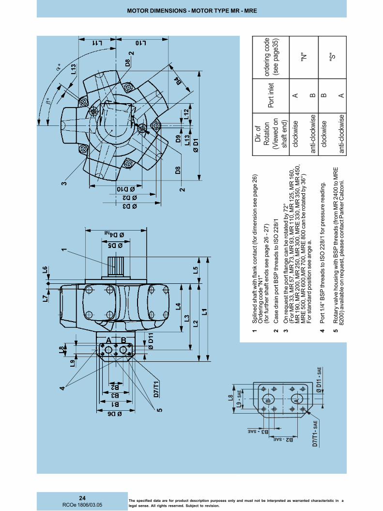
1S
plin
ed s
haft w
ith fla
nk c
onta
ct (f
or dim
ensio
n s
ee p
age 2
6)
Ord
ering c
ode "N
1"
(for fu
rther shaft e
nds s
ee p
age 2
6 - 2
7)
2C
ase d
rain
port
BS
P thre
ads to IS
O 2
28/1
3O
n request th
e p
ort
fla
nge c
an b
e rota
ted b
y 7
2°
(For M
R 3
3, M
R 5
7, M
R 7
3, M
R 9
3, M
R 1
10, M
R 1
25, M
R 1
60,
MR
190, M
R 2
00, M
R 2
50, M
R 3
00, M
RE
330, M
R 3
50, M
R 4
50,
MR
E 5
00, M
R 6
00,M
R 7
00, M
RE
800 c
an b
e rota
ted b
y 3
6°)
For sta
ndard
positio
n s
ee a
nge a
.
4P
ort
1/4
“ B
SP
thre
ads to IS
O 2
28/1
for pre
ssure
readin
g.
5R
ota
ry v
alv
e h
ousin
g w
ith B
SP
thre
ads (fr
om
MR
2400 to M
RE
8200) availa
ble
on request, p
lease c
onta
ct P
ark
er C
alz
oni.
5

25RCOe 1806/03.05
The specified data are for product description purposes only and must not be interpreted as warranted characteristic in a
legal sense. All rights reserved. Subject to revision.
MOTOR DIMENSIONS - MOTOR TYPE MR - MRE
RO
TO
MR
OT
OM
RO
TO
MR
OT
OM
RO
TO
ME
PY
T1
L1
L1
L1
L1
L2
L2
L2
L2
L2
L3
L3
L3
L3
L3
L4
L4
L4
L4
L4
L5
L5
L5
L5
L5
L6
L6
L6
L6
L6
L7
L7
L7
L7
L7
L8
L8
L8
L8
L8
L9
L9
L9
L9
L9
LE
AS
-9
LE
AS
-9
LE
AS
-9
LE
AS
-9
LE
AS
-9
L0
1L
01
L0
1L
01
L0
1L
11
L1
1L
11
L1
1L
11
L2
1L
21
L2
1L
21
L2
1L
31
L3
1L
31
L3
1L
31
Laa aaa
bb bbbw
ol*
wol
*w
ol*
wol
*w
ol*
er
us
se
rp
hgi
h*
hgi
h*
hgi
h*
hgi
h*
hgi
h*
er
us
se
rp
33
RM
33
RM
33
RM
33
RM
33
RM
75
RM
5,
35
26
91
84
17
01
2,
75
41
91
07
--
4,
25
2,
01
15
,8
70
77
,9
1°
80
1°
63
37
RM
37
RM
37
RM
37
RM
37
RM
39
RM
01
1R
M7
92
5,
82
25
,0
91
5,
13
15
,8
67
10
24
54
3-
-8
,9
11
49
27
-°
09
°6
3
52
1R
M5
21
RM
52
1R
M5
21
RM
52
1R
M0
61
RM
09
1R
M9
03
24
24
02
54
17
64
16
14
54
3-
-5
,7
41
30
12
75
,6
°0
9°
63
00
2R
M0
02
RM
00
2R
M0
02
RM
00
2R
M0
52
RM
00
3R
M0
33
ER
M
32
32
42
40
25
41
18
51
61
45
43
--
5,
35
19
11
27
5,
7°
09
°6
3
05
3R
M0
53
RM
05
3R
M0
53
RM
05
3R
M0
54
RM
00
5E
RM
67
39
72
53
27
61
79
51
81
4,
07
04
--
5,
47
10
31
48
5,
9°
09
°6
3
00
6R
M0
06
RM
00
6R
M0
06
RM
00
6R
M0
07
RM
00
8E
RM
00
49
92
55
27
81
10
15
10
24
,0
70
4-
-2
91
34
14
88
°0
9°
63
00
11
RM
00
11
RM
00
11
RM
00
11
RM
00
11
RM
00
41
ER
M8
54
14
33
92
30
27
11
02
22
28
05
--
--
32
25
61
50
19
°4
01
°6
3
00
61
RM
00
61
RM
00
61
RM
00
61
RM
00
61
RM
00
81
RM
00
12
ER
M6
05
47
36
23
63
22
31
12
42
28
05
--
--
46
27
91
50
11
1°
09
°6
3
00
42
RM
00
42
RM
00
42
RM
00
42
RM
00
42
RM
00
82
RM
00
13
ER
M9
16
66
42
93
58
23
51
42
62
53
12
65
8,
96
4,
97
30
31
22
32
15
1°
09
°6
3
00
63
RM
00
63
RM
00
63
RM
00
63
RM
00
63
RM
00
54
RM
00
45
ER
M5
,9
96
5,
98
45
,8
14
5,
70
30
12
43
82
53
18
67
7,
77
28
,6
95
,9
53
74
23
21
91
°8
01
°6
3
00
56
RM
00
56
RM
00
56
RM
00
56
RM
00
56
RM
00
07
RM
00
28
ER
M6
97
66
55
94
48
30
32
73
03
53
18
67
7,
77
28
,6
93
,7
04
74
23
21
12
°8
01
°6
3
** ***i
no
zla
CR
EK
RA
PT
LU
SN
OC
ES
AE
LP
,D
AE
RH
TC
NU
EL
BA
LI
AV
AO
SL
A-
-S
EU
LA
V"
IS
PE
AS
""
SE
GN
AL
FN
OI
TC
EN
NO
CE
AS
"2
4.
GA
PO
TR
EF
ER
ES
AE
LP
SE
UL
AV
ER
US
SE
RP
RO
F
RO
TO
MR
OT
OM
RO
TO
MR
OT
OM
RO
TO
ME
PY
T1
B1
B1
B1
B1
B2
B2
B2
B2
B2
BE
AS
-2
BE
AS
-2
BE
AS
-2
BE
AS
-2
BE
AS
-2
B3
B3
B3
B3
B3
B4
B4
B4
B4
B4
BE
AS
-4
BE
AS
-4
BE
AS
-4
BE
AS
-4
BE
AS
-4
BØØ ØØØ
1D
ØØ ØØØ2
DØØ ØØØ3
D
ØØ ØØØ 4D
8h
8h
8h
8h
8h
***
**
**
**
*ØØ ØØØ5
DØØ ØØØ6
D1
T-
7D
1T
-7
D1
T-
7D
1T
-7
D1
T-
7D
EA
S-
1T
-7
DE
AS
-1
T-
7D
EA
S-
1T
-7
DE
AS
-1
T-
7D
EA
S-
1T
-7
D8
D8
D8
D8
D8
D9
D9
D9
D9
D9
DØØ ØØØ
01
DØØ ØØØ
11
D
EA
S-
11
DØ
EA
S-
11
DØ
EA
S-
11
DØ
EA
S-
11
DØ
EA
S-
11
DØ
WO
L*
WO
L*
WO
L*
WO
L*
WO
L*
.S
SE
RP
HGI
H*
HGI
H*
HGI
H*
HGI
H*
HGI
H*
.S
SE
RP
WO
L*
WO
L*
WO
L*
WO
L*
WO
L*
.S
SE
RP
HGI
H*
HGI
H*
HGI
H*
HGI
H*
HGI
H*
.S
SE
RP
WO
L*
WO
L*
WO
L*
WO
L*
WO
L*
.S
SE
RP
HGI
H*
HGI
H*
HGI
H*
HGI
H*
HGI
H*
.S
SE
RP
WO
L*
WO
L*
WO
L*
WO
L*
WO
L*
.S
SE
RP
HGI
H*
HGI
H*
HGI
H*
HGI
H*
HGI
H*
.S
SE
RP
33
RM
33
RM
33
RM
33
RM
33
RM
75
RM
42
1-
-5
62
,6
2-
-4
,9
64
,5
32
06
10
81
52
1-
02
1-
52
-0
1M
4/
1G
97
9-
-5
2
37
RM
37
RM
37
RM
37
RM
37
RM
39
RM
01
1R
M0
21
05
--
00
10
9-
-0
52
40
24
,4
22
54
1-
92
15
1-
8M
--
8/
3G
11
-0
2-
-
52
1R
M5
21
RM
52
1R
M5
21
RM
52
1R
M0
61
RM
09
1R
M0
21
05
--
00
10
01
--
2,
31
35
22
94
20
61
-9
21
51
-8
M-
-8
/3
G1
10
61
02
--
00
2R
M0
02
RM
00
2R
M0
02
RM
00
2R
M0
52
RM
00
3R
M0
33
ER
M
02
10
5-
-0
01
00
1-
-8
23
23
26
52
57
10
99
21
51
-8
M-
-8
/3
G1
12
61
02
--
05
3R
M0
53
RM
05
3R
M0
53
RM
05
3R
M0
54
RM
00
5E
RM
24
10
6-
-0
21
91
1-
-8
63
66
26
92
09
16
96
51
81
-0
1M
--
8/
3G
31
49
15
2-
-
00
6R
M0
06
RM
00
6R
M0
06
RM
00
6R
M0
07
RM
00
8E
RM
24
10
6-
-0
21
33
1-
-5
04
09
20
23
02
22
01
65
18
1-
01
M-
8/
3G
31
70
25
2-
00
11
RM
00
11
RM
00
11
RM
00
11
RM
00
11
RM
00
41
ER
M2
61
37
--
--
63
18
41
--
--
07
40
33
76
30
52
02
12
71
12
-2
1M
--
--
2/
1G
51
82
21
3-
--
-
00
61
RM
00
61
RM
00
61
RM
00
61
RM
00
61
RM
00
81
RM
00
12
ER
M2
61
37
--
--
63
18
61
--
--
85
50
83
32
40
92
84
12
71
12
-2
1M
--
--
2/
1G
71
66
21
3-
--
-
00
42
RM
00
42
RM
00
42
RM
00
42
RM
00
42
RM
00
82
RM
00
13
ER
M3
32
68
68
10
10
81
09
17
,5
35
,6
32
46
04
44
94
53
30
41
51
28
2-
41
M0
3-
21
M5
3-
61
M2
/1
G9
14
13
73
73
73
00
63
RM
00
63
RM
00
63
RM
00
63
RM
00
63
RM
00
54
RM
00
45
ER
M3
32
61
16
11
61
10
02
04
28
8,
24
54
,4
46
67
04
57
95
00
4 4D
4D
4D
4D
4D
7h
7h
7h
7h
7h
***
**
**
**
*-
51
28
2-
61
M0
3-
21
M4
3-
02
M2
/1
G3
20
83
83
05
05
00
56
RM
00
56
RM
00
56
RM
00
56
RM
00
56
RM
00
07
RM
00
28
ER
M3
32
61
16
11
61
10
02
46
28
8,
24
54
,4
44
68
00
66
,8
56
05
4 4D
4D
4D
4D
4D
7h
7h
7h
7h
7h
***
**
**
**
*0
91
51
28
2-
61
M0
3-
21
M4
3-
02
M2
/1
G5
20
54
83
05
05
** ***C
RE
KR
AP
TL
US
NO
CE
SA
EL
P,
DA
ER
HT
CN
UE
LB
AL
IA
VA
OS
LA
,S
EU
LA
V"
IS
PE
AS
""
SE
GN
AL
FN
OI
TC
EN
NO
CE
AS
"2
4.
GA
PO
TR
EF
ER
ES
AE
LP
SE
UL
AV
ER
US
SE
RP
RO
Fi
no
zla

26RCOe 1806/03.05
The specified data are for product description purposes only and must not be interpreted as warranted characteristic in a
legal sense. All rights reserved. Subject to revision.
SHAFT END DIMENSIONS - MOTOR TYPE MR - MRE
1)
on e
nquiry
Co
de B
1 -
BS
3550 -
1)
Co
de
D
1 -
DIN
5480
Co
de N
1 (
Sta
ndard
)
ois
re
Vn
1N
1N
1N
1N
1N
1B
1B
1B
1B
1B
1D
1D
1D
1D
1D
EP
YT
EP
YT
EP
YT
EP
YT
EP
YT
5L
5L
5L
5L
5L
12
L1
2L
12
L1
2L
12
L2
2L
22
L2
2L
22
L2
2L
21
D2
1D
21
D2
1D
21
D0
1T
01
T0
1T
01
T0
1T
31
DØ
31
DØ
31
DØ
31
DØ
31
DØ
5L
5L
5L
5L
5L
12
L1
2L
12
L1
2L
12
L2
2L
22
L2
2L
22
L2
2L
21
D2
1D
21
D2
1D
21
D0
1T
01
T0
1T
01
T0
1T
31
DØ
31
DØ
31
DØ
31
DØ
31
DØ
5L
5L
5L
5L
5L
12
L1
2L
12
L1
2L
12
L2
2L
22
L2
2L
22
L2
2L
21
D2
1D
21
D2
1D
21
D0
1T
01
T0
1T
01
T0
1T
31
DØ
31
DØ
31
DØ
31
DØ
31
DØ
33
RM
75
RM
75
04
82
--
23
x6
2x
6B
--
--
--
75
04
82
--
e8
-0
2x
5,
1x
23
W
37
RM
39
RM
01
1R
M
5,
86
8,
44
5,
13
21
M-
43
x8
2x
6B
--
--
--
5,
86
5,
15
5,
13
21
M-
e8
-6
1x
2x
53
W
52
1R
M
06
1R
M
09
1R
M
76
05
5,
53
21
M0
28
3x
23
x8
B7
60
55
,5
32
1M
02
71
-4
2/
21
76
05
5,
53
21
M0
2e
8-
81
x2
x8
3W
*0
02
RM
--
--
--
--
--
--
--
--
--
05
2R
M
00
3R
M
03
3E
RM
18
06
64
21
M5
28
4x
24
x8
B1
80
65
42
1M
52
12
-4
2/
21
18
06
64
21
M5
2e
8-
22
x2
x8
4W
05
3R
M
05
4R
M
00
5E
RM
79
47
5,
65
21
M5
24
5x
64
x8
B7
94
71
62
1M
52
71
-6
1/
87
94
70
62
1M
52
e8
-7
1x
3x
55
W
00
6R
M
00
7R
M
00
8E
RM
10
18
72
62
1M
52
06
x2
5x
8B
10
18
72
62
1M
52
71
-6
1/
81
01
87
26
21
M5
2e
8-
81
x3
x0
6W
00
11
RM
00
41
ER
M7
11
88
96
21
M5
22
7x
26
x8
B7
11
88
76
21
M5
24
1-
21
/6
71
18
82
72
1M
52
e8
-2
2x
3x
07
W
00
61
RM
00
81
RM
00
12
ER
M
23
10
01
97
21
M5
22
8x
27
x0
1B
23
10
01
67
21
M5
20
2-
21
/6
23
10
01
08
21
M5
2e
8-
52
x3
x0
8W
00
42
RM
00
82
RM
00
13
ER
M
35
10
21
99
21
M5
22
9x
28
x0
1B
35
10
21
67
21
M5
20
2-
21
/6
35
10
21
00
12
1M
52
e8
-1
2x
4x
09
W
00
63
RM
00
54
RM
00
45
ER
M
01
23
71
44
12
1M
52
21
1x
20
1x
01
B0
12
37
15
,2
41
21
M5
20
2-
21
/6
01
23
71
44
12
1M
52
e8
-6
2x
4x
01
1W
00
56
RM
00
07
RM
00
28
ER
M
03
28
81
05
12
1M
52
52
1x
21
1x
01
B0
32
88
13
51
21
M5
26
2-
21
/6
03
28
81
35
12
1M
52
e8
-8
2x
4x
02
1W
eh
ty
bd
eri
uq
er
sn
ois
ne
mid
sel
oh
eh
te
sa
cn
I.
sel
oh
eci
vr
es
sa
de
re
dis
no
ce
bt
su
m"
1D
"d
na
"1
B"
,"
1N
"s
noi
sr
ev
tf
ah
se
ht
ro
f)
01
T/
21
D(
sel
oh
de
da
er
ht
eh
t:
ET
ON
.in
ozl
aC
RE
KR
AP
tc
at
no
ce
sel
p,
ev
ob
ae
re
hd
et
sils
en
oe
ht
mo
rf
tn
er
ef
fid
er
an
oit
acil
pp
a
"1
F"
ed
oc
yln
o*
00
2R
M

27RCOe 1806/03.05
The specified data are for product description purposes only and must not be interpreted as warranted characteristic in a
legal sense. All rights reserved. Subject to revision.
SHAFT END DIMENSIONS - MOTOR TYPE MR - MRE
Co
de
P 1
Co
de F
1 -
DIN
5480 -
noi
sr
eV
1F
1F
1F
1F
1F
1P
1P
1P
1P
1P
ep
yT
ep
yT
ep
yT
ep
yT
ep
yT
5L
5L
5L
5L
5L
12
L1
2L
12
L1
2L
12
L2
2L
22
L2
2L
22
L2
2L
31
DØ
31
DØ
31
DØ
31
DØ
31
DØ NI
D0
84
55
L5
L5
L5
L5
L1
2L
12
L1
2L
12
L1
2L
62
L6
2L
62
L6
2L
62
L2
1D
21
D2
1D
21
D2
1D
01
T0
1T
01
T0
1T
01
T4
1D
Ø4
1D
Ø4
1D
Ø4
1D
Ø4
1D
Øy
eK
ye
Ky
eK
ye
Ky
eK
Bx
L
de
tti
ms
na
rT
de
tti
ms
na
rT
de
tti
ms
na
rT
de
tti
ms
na
rT
de
tti
ms
na
rT
eu
qr
ot
)m
N(
ET
ON
ET
ON
ET
ON
ET
ON
ET
ON
ot
eu
qr
ot
eh
tf
os
eul
av
re
hgi
hr
oF
tlu
sn
oc
es
ael
p,
de
tti
ms
na
rt
eb
in
ozl
aC
RE
KR
AP
in
ozl
aC
RE
KR
AP
in
ozl
aC
RE
KR
AP
in
ozl
aC
RE
KR
AP
in
ozl
aC
RE
KR
AP
i
33
RM
75
RM
71
51
2H
9-
12
x5
2,
1x
82
N-
--
--
--
37
RM
39
RM
01
1R
M
71
56
2H
9-
41
x2
x2
3N
--
--
--
-
52
1R
M
06
1R
M
09
1R
M
41
58
2H
9-
61
x2
x5
3N
76
05
34
21
M0
26
k0
42
1x
54
69
4
*0
02
RM
72
56
3H
9-
81
x2
x0
4N
--
--
--
--
05
2R
M
00
3R
M
03
3E
RM
72
56
3H
9-
81
x2
x0
4N
18
06
5,
35
21
M5
26
k0
54
1x
65
79
8
05
3R
M
05
4R
M
00
5E
RM
82
58
3H
9-
22
x2
x7
4N
79
47
95
21
M5
26
k5
56
1x
07
31
41
00
6R
M
00
7R
M
00
8E
RM
82
54
4H
9-
71
x3
x5
5N
10
18
74
62
1M
52
6k
06
81
x0
70
30
2
00
11
RM
00
41
ER
M8
38
05
H9
-0
2x
3x
56
N7
11
88
5,
67
21
M5
26
k0
70
2x
08
09
62
00
61
RM
00
81
RM
00
12
ER
M
74
87
5H
9-
42
x3
x5
7N
23
10
01
58
21
M5
26
k0
82
2x
09
02
04
00
42
RM
00
82
RM
00
13
ER
M
84
82
6H
9-
72
x3
x5
8N
35
10
21
59
21
M5
26
k0
95
2x
01
17
02
6
00
63
RM
00
54
RM
00
45
ER
M
05
41
86
H9
-2
3x
3x
00
1N
01
23
71
61
12
1M
52
6k
01
18
2x
06
17
57
01
00
56
RM
00
07
RM
00
28
ER
M
05
41
67
H9
-5
3x
3x
01
1N
03
28
81
83
1
**
21
M5
28
b4
21
23
x0
81
-2
°N
07
28
2
er
an
oit
acil
pp
ae
ht
yb
de
riu
qe
rs
noi
sn
emi
ds
elo
he
ht
es
ac
nI
.s
elo
he
civ
re
ss
ad
er
edi
sn
oc
eb
ts
um
"1
P"
sn
ois
re
vt
fa
hs
eh
tr
of
)0
1T
/2
1D
(s
elo
hd
ed
ae
rh
te
ht
:E
TO
N
.in
ozl
aC
RE
KR
AP
tc
at
no
ce
sel
p,
ev
ob
ae
re
hd
et
sils
en
oe
ht
mo
rf
tn
er
ef
fid
"1
F"
ed
oc
yln
o*
00
2R
M
sy
ek
ow
ts
ed
ulc
nin
ois
ne
mid
sih
T*
*
Co
de P
1 *
*
On
ly M
R 6
500, M
R 7
000,
MR
E 8
20
0

28RCOe 1806/03.05
The specified data are for product description purposes only and must not be interpreted as warranted characteristic in a
legal sense. All rights reserved. Subject to revision.
COMPONENTS FOR SPEED CONTROL - MOTOR TYPE MR - MRE
MECHANICAL
TACHOMETER DRIVE
TACHOGENERATOR
DRIVE
ENCODERDRIVE
INCREMENTAL ENCODER
DIMENSIONS
encoder
encoder drive flangeprotection
(see page 25)
Female connector included in the supply
α = 126° for the motor types MR 33-57
α = 54° for the motor types MR 73-93-110-125-
160-190-200-250-300 MRE 330
α =45° for the other types
α
( ) * Motor MR 73-93-110-125-160-190-200-250-300 MRE 330
( )** Motor MR 33-57
Code "C1" Code "T1" Code "Q1"
2x M8x45 (2x M8x50)* 2x M8x45 (2x M8x50)* 2x M8x30 (2x M8x35)*
(27)**
(62)**
(27)**(27)**

29RCOe 1806/03.05
The specified data are for product description purposes only and must not be interpreted as warranted characteristic in a
legal sense. All rights reserved. Subject to revision.
COMPONENTS FOR SPEED CONTROL - MOTOR TYPE MR - MRE
Encoder type: ELCIS mod. 478
Supply voltage: 8 to 24 Vcc
Current consumption: 120 mA max
Current output: 10 mA max
Output signal: A phase- MONODIRECTIONAL
A and B phase BIDIRECTIONAL
Response frequency: 100 KHz max
Number of pulses: 500 (others on request - max 2540)
Slew speed: Always compatible with maximum
motor speed
Operating temperature range: from 0 to 70 °C
Storage temperature range: from -30 to +85 °C
Ball bearing life: 1.5x10⁹ rpm
Weigth: 100 gr
Protection degree: IP 67 (with protection and
connector assembled)
Connectors:
MONODIRECTIONAL RSF3/0.5 M (Lumberg) male
RKT3-06/5m (Lumberg) female
BIDIRECTIONAL RSF4/0.5 M (Lumberg) male
RKT4-07/5m (Lumberg) female
Note: Female connectors cable length equal to 5 m.
INCREMENTAL ENCODER
TECHNICAL DATA
Monodirectional
4 3 3 4
1 1
4 3 3 4
1 1
1 1 1
4 4
1
4 4
3 3 3 3
2 2
Female
connector
Male
connector
Male
connector
INCREMENTAL ENCODER
CONNECTION DIAGRAMS
Bidirectional
2 2
Female
connector
noitcnufdnaseriwroloC noitcnufdnaseriwroloC noitcnufdnaseriwroloC noitcnufdnaseriwroloC noitcnufdnaseriwroloC
11111 nworB nworB nworB nworB nworB )cdV42ot8(ylppuSrewoP
22222 etihW etihW etihW etihW etihW )ccV42-Am01XAM(esahpBtuptuO
33333 eulB eulB eulB eulB eulB )cdV0(ylppuSrewoP
44444 kcalB kcalB kcalB kcalB kcalB )ccV42-Am01XAM(esahpAtuptuO

30RCOe 1806/03.05
The specified data are for product description purposes only and must not be interpreted as warranted characteristic in a
legal sense. All rights reserved. Subject to revision.
PIPE CONNECTION FLANGES - MOTOR TYPE MR - MRE
STANDARD CONNECTION FLANGECode “C1“
Flange is supplied complete with screws and seals.
SAE CONNECTION FLANGECodice “S1“Codice “T1“Codice “G1“Codice “L1“
Permitted up to 6000 PSI
RMRMRMRMRMERM
DDDDD)PSB(
HHHHHGNIREDRO GNIREDRO GNIREDRO GNIREDRO GNIREDRO
EDOC
RBN RBN RBN RBN RBN
GNIREDRO GNIREDRO GNIREDRO GNIREDRO GNIREDROEDOC
MPF MPF MPF MPF MPF
011-39-37 011-39-37 011-39-37 011-39-37 011-39-37091-061-521
052-002033-003
"4/3 83 890262 493922
054-053 054-053 054-053 054-053 054-053005
007-006008
"4/11 93 980262 593922
0041-0011 0041-0011 0041-0011 0041-0011 0041-00110081-0061
0012"2/11 54 390262 693922
0082-0042 0082-0042 0082-0042 0082-0042 0082-00420013
"2/11 95 275462 793922
0054-0063 0054-0063 0054-0063 0054-0063 0054-00630045
0007-00560028
"2 85 427272 893922
RMRMRMRMRMERM
EAS EAS EAS EAS EASISP
DDDDD
HHHHH IIIII XXXXX YYYYY
CIRTEM CIRTEM CIRTEM CIRTEM CIRTEM CNU CNU CNU CNU CNU
"""""mmmmmmmmmm
T/Z T/Z T/Z T/Z T/ZGNIREDRO GNIREDRO GNIREDRO GNIREDRO GNIREDRO
EDOC
RBN RBN RBN RBN RBN)"(Z )"(Z )"(Z )"(Z )"(Z TTTTT
GNIREDRO GNIREDRO GNIREDRO GNIREDRO GNIREDRO
RBN RBN RBN RBN RBN
011-39-37 011-39-37 011-39-37 011-39-37 011-39-37091-061-521
052-002033-003
0005 "4/3 91 83 55 2,22 6,74 52/01M 592772 61-"8/3 52 533322
054-053 054-053 054-053 054-053 054-053005
007-006008
0005 "1 52 93 06 2,62 4,25 52/01M 792772 61-"8/3 52 633322
0041-0011 0041-0011 0041-0011 0041-0011 0041-00110061-0081
0012
0004 "4/11 13 54 57 2,03 7,85 52/01M 992772 41-"61/7 03 733322
0006 "1 52 54 17 8,72 51,75 22/21M 661032 41-"61/7 03 290243
0082-0042 0082-0042 0082-0042 0082-0042 0082-00420013
0003 "2/11 73 95 68 7,53 8,96 03/21M 103772 31-"2/1 03 833322
0006 "2/11 73 95 001 5,63 4,97 03/61M 861032 11-"8/5 53 860943
0054-0063 0054-0063 0054-0063 0054-0063 0054-00630045
0007-00560028
0003 "2 05 85 211 9,24 8,77 03/21M 303772 31-"2/1 03 933322
0006 "2 05 85 611 54,44 28,69 53/02M 071032 01-"4/3 83 745243
Flange is supplied complete with screws and seals. FPM seals enquiry.
BSP threads to ISO 228/1

31RCOe 1806/03.05
The specified data are for product description purposes only and must not be interpreted as warranted characteristic in a
legal sense. All rights reserved. Subject to revision.
COUPLINGS - KEY ADAPTERS - MOTOR TYPE MR - MRE
COUPLINGS
1 For standard male splined shaft version "N1" (see page 26).
ADAPTERS WITH KEY
1
RMRMRMRMRMERM
GNIREDRO GNIREDRO GNIREDRO GNIREDRO GNIREDROEDOC
RRRRR3645NIDXE
)mm(ddddd IIIII DDDDD 6k6k6k6k6k LLLLL bbbbb ttttt
)mm(yeK )mm(yeK )mm(yeK )mm(yeK )mm(yeK5886NID
061-521 061-521 061-521 061-521 061-521091
711172 83x23x8A 3,83 5,51 85 05 01 16 54x8x01
003-052 003-052 003-052 003-052 003-052033
811172 84x24x8A 3,84 51 07 06 41 5,37 65x9x41
054-053 054-053 054-053 054-053 054-053005
911172 45X64x8A 3,45 5,81 08 57 61 48 07x01x61
007-006 007-006 007-006 007-006 007-006008
021172 06x25x8A 3,06 91 09 08 81 49 07x11x81
0041-0011 0041-0011 0041-0011 0041-0011 0041-0011 121172 27x26x8A 3,27 02 501 89 02 5,901 09x21x02
0081-0061 0081-0061 0081-0061 0081-0061 0081-00610012
221172 28x27x01A 3,28 22 811 811 22 321 011x41x22
0082-0042 0082-0042 0082-0042 0082-0042 0082-00420013
321172 29x28x01A 3,29 92 031 841 52 531 041x41x52
0054-0063 0054-0063 0054-0063 0054-0063 0054-00630045
917272 211x201x01A 3,211 03 061 881 82 661 081x61x82
0007-0056 0007-0056 0007-0056 0007-0056 0007-00560028
674322 521x211x01A 6,521 83 581 881 54 591 081x52x54
RMRMRMRMRMERM
GNIREDRO GNIREDRO GNIREDRO GNIREDRO GNIREDROEDOC
AAAAA BBBBB CCCCC11H 11H 11H 11H 11H
DDDDD EEEEE FFFFF GGGGG
061-521 061-521 061-521 061-521 061-521091
302564 411 65 93 74 45 5,51 5,43
003-052 003-052 003-052 003-052 003-052033
202564 531 17 94 06 46 51 54
054-053 054-053 054-053 054-053 054-053005
102564 551 08 55 86 86 5,81 5,55
007-006 007-006 007-006 007-006 007-006008
002564 171 09 16 57 08 91 95
0011 0011 0011 0011 00110041
587464 681 601 37 5,88 5,58 02 5,56
0081-0061 0081-0061 0081-0061 0081-0061 0081-00610012
991564 422 811 38 89 701 22 87
0082-0042 0082-0042 0082-0042 0082-0042 0082-00420013
891564 562 231 39 211 721 32 79
0054-0063 0054-0063 0054-0063 0054-0063 0054-00630045
296474 553 051 311 621 561 03 041
0007-0056 0007-0056 0007-0056 0007-0056 0007-00560028
445224 093 591 621 041 581 83 741
2
1 For standard male splined shaft version "N1" (see page 26).
2 Key to DIN 6885
1

32RCOe 1806/03.05
The specified data are for product description purposes only and must not be interpreted as warranted characteristic in a
legal sense. All rights reserved. Subject to revision.
HOLDING BRAKE UNIT DIMENSIONS - MOTOR TYPE MR - MRE
EPYTEKARB EPYTEKARB EPYTEKARB EPYTEKARB EPYTEKARB 091B 091B 091B 091B 091B 003B 003B 003B 003B 003B 054B 054B 054B 054B 054B 007B 007B 007B 007B 007B 0011B 0011B 0011B 0011B 0011B 0081B 0081B 0081B 0081B 0081B 0082B 0082B 0082B 0082B 0082B
EPYTROTOM EPYTROTOM EPYTROTOM EPYTROTOM EPYTROTOMERM-RM
061-521 061-521 061-521 061-521 061-521091
003-052 003-052 003-052 003-052 003-052033
054-053 054-053 054-053 054-053 054-053005
007-006 007-006 007-006 007-006 007-006008
0041-0011 0041-0011 0041-0011 0041-0011 0041-0011 0081-0061 0081-0061 0081-0061 0081-0061 0081-00610012
0082-0042 0082-0042 0082-0042 0082-0042 0082-00420013
Same dimensionsstandard male splinedshaft version "N1"(see page 26)
ααααα1, ααααα2 Corresponding angles to the release ports 1 and 2, to case the drain ports 1 and 2
Release portsCase drain ports
Release portsCase drain ports
Case drain portsRelease ports
øD
2
D7
L1
L11
D1
L10
L6
D6L7
L5
L4
øD
4h
8
øD
9N
°5
HO
LE
S
L2
L3
øD
5
D1
2
T10
L21L22
øD
3
øD
13
EPYTEKARB EPYTEKARB EPYTEKARB EPYTEKARB EPYTEKARB 1L1L1L1L1L 2L2L2L2L2L 3L3L3L3L3L 4L4L4L4L4L 5L5L5L5L5L 6L6L6L6L6L 7L7L7L7L7L 01L 01L 01L 01L 01L 11L 11L 11L 11L 11L 12L 12L 12L 12L 12L 22L 22L 22L 22L 22L 1D1D1D1D1D 2D2D2D2D2D 3D3D3D3D3D 4D4D4D4D4D 8h8h8h8h8h 5D5D5D5D5D 6D6D6D6D6D 7D7D7D7D7D 9D9D9D9D9D 21D 21D 21D 21D 21D 31D 31D 31D 31D 31D 01T 01T 01T 01T 01T aaaaa11111 aaaaa22222
091B 121 - 22 41 76 14 3,92 02 27 05 5,53
62egapees
elbitapmoc
1D1Nedoc
052 522 061 - "4/1G '8/3G 5,01 21M
egapees
72-62
edoc
1F-1D-1N
82'03°22 '03°22
003B 631 - 52 51 18 24 5,93 12 68 06 64 652 232 571 - "4/1G '8/3G 5,01 21M 82 '03°22 '03°22
054B 741 - 72 51 79 5,94 63 42 001 47 5,65 692 662 091 - "4/1G '8/3G 5,31 21M 82 '03°22 '03°22
007B 271 - 82 51 101 55 64 52 501 87 26 023 092 022 - "4/1G '8/3G 5,31 21M 82 '03°22 '03°22
0011B 881 02 62 42 711 17 5,35 84 021 88 27 063 033 052 021 "4/1G '2/1G 51 21M 82 °0 °0
0081B 612 - 82 12 231 5,36 5,85 43 531 001 97 324 083 092 - "4/1G '2/1G 5,71 21M 82 '03°22 '03°22
0082B 362 - 03 42 351 78 76 5,24 561 021 99 494 044 533 - "4/1G '2/1G 91 21M 82 '03°22 '03°22
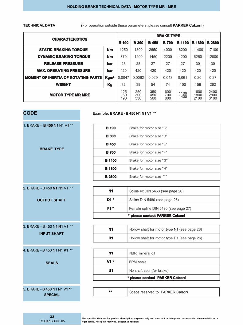
33RCOe 1806/03.05
The specified data are for product description purposes only and must not be interpreted as warranted characteristic in a
legal sense. All rights reserved. Subject to revision.
HOLDING BRAKE TECHNICAL DATA - MOTOR TYPE MR - MRE
TECHNICAL DATA (For operation outside these parameters, please consult PARKER Calzoni)
SCITSIRETCARAHC SCITSIRETCARAHC SCITSIRETCARAHC SCITSIRETCARAHC SCITSIRETCARAHCEPYTEKARB EPYTEKARB EPYTEKARB EPYTEKARB EPYTEKARB
091B 091B 091B 091B 091B 003B 003B 003B 003B 003B 054B 054B 054B 054B 054B 007B 007B 007B 007B 007B 0011B 0011B 0011B 0011B 0011B 0081B 0081B 0081B 0081B 0081B 0082B 0082B 0082B 0082B 0082B
EUQROTGNIKARBCITATS EUQROTGNIKARBCITATS EUQROTGNIKARBCITATS EUQROTGNIKARBCITATS EUQROTGNIKARBCITATS mNmNmNmNmN 0521 0081 0562 0004 0026 00411 00171
EUQROTGNIKARBCIMANYD EUQROTGNIKARBCIMANYD EUQROTGNIKARBCIMANYD EUQROTGNIKARBCIMANYD EUQROTGNIKARBCIMANYD mNmNmNmNmN 078 0021 0541 0022 0024 0526 00021
ERUSSERPESAELER ERUSSERPESAELER ERUSSERPESAELER ERUSSERPESAELER ERUSSERPESAELER rab rab rab rab rab 82 82 72 72 72 03 03
ERUSSERPGNITAREPO.XAM ERUSSERPGNITAREPO.XAM ERUSSERPGNITAREPO.XAM ERUSSERPGNITAREPO.XAM ERUSSERPGNITAREPO.XAM rab rab rab rab rab 024 024 024 024 024 024 024
STRAPGNITATORFOAITRENIFOTNEMOM STRAPGNITATORFOAITRENIFOTNEMOM STRAPGNITATORFOAITRENIFOTNEMOM STRAPGNITATORFOAITRENIFOTNEMOM STRAPGNITATORFOAITRENIFOTNEMOM mgK mgK mgK mgK mgK 22222 7400,0 2600,0 920,0 340,0 160,0 02,0 72,0
THGIEW THGIEW THGIEW THGIEW THGIEW gKgKgKgKgK 23 93 45 47 001 851 262
ERMRMEPYTROTOM ERMRMEPYTROTOM ERMRMEPYTROTOM ERMRMEPYTROTOM ERMRMEPYTROTOM521061091
052003033
053054005
006007008
00110041
006100810012
004200820013
CODE Example: BRAKE - B 450 N1 N1 V1 **
091B 091B 091B 091B 091B "C"ezisrotomrofekarB
003B 003B 003B 003B 003B "D"ezisrotomrofekarB
054B 054B 054B 054B 054B "E"ezisrotomrofekarB
007B 007B 007B 007B 007B "F"ezisrotomrofekarB
0011B 0011B 0011B 0011B 0011B "G"ezisrotomrofekarB
0081B 0081B 0081B 0081B 0081B "H"ezisrotomrofekarB
0082B 0082B 0082B 0082B 0082B "I"ezisrotomrofekarB
1. BRAKE - B 450 N1 N1 V1 **
********** inozlaCREKRAPotdevreserecapS
1N1N1N1N1N liolarenim:RBN
*1V *1V *1V *1V *1V slaesMPF
1U1U1U1U1U )ekarbrof(laestfahsoN
inozlaCREKRAPtcatnocesaelp* inozlaCREKRAPtcatnocesaelp* inozlaCREKRAPtcatnocesaelp* inozlaCREKRAPtcatnocesaelp* inozlaCREKRAPtcatnocesaelp*
4. BRAKE - B 450 N1 N1 V1 **
1N1N1N1N1N )62egapees(3645NIDxeenilpS
*1D *1D *1D *1D *1D )62egapees(0845NIDenilpS
*1F *1F *1F *1F *1F )72egapees(0845NIDenilpselameF
inozlaCREKRAPtcatnocesaelp* inozlaCREKRAPtcatnocesaelp* inozlaCREKRAPtcatnocesaelp* inozlaCREKRAPtcatnocesaelp* inozlaCREKRAPtcatnocesaelp*
2. BRAKE - B 450 N1 N1 V1 **
5. BRAKE - B 450 N1 N1 V1 **
BRAKE TYPE
OUTPUT SHAFT
SEALS
SPECIAL
1N1N1N1N1N )62egapees(1NepytrotomroftfahswolloH
1D1D1D1D1D )62egapees(1DepytrotomroftfahswolloH
3. BRAKE - B 450 N1 N1 V1 **
INPUT SHAFT

34RCOe 1806/03.05
The specified data are for product description purposes only and must not be interpreted as warranted characteristic in a
legal sense. All rights reserved. Subject to revision.
INSTALLATION NOTES - MOTOR TYPE MR - MRE
Mounting
Any mounting position- Note the position of the case drain port
(see below)
Install the motor properly- Mounting surface must be flat and resistant
to bending
Min. tensile strength of mounting screws toDIN 267 Part 3 class 10.9
- Note the prescribed fastening torque
Pipes, pipe connections
Use suitable screws!- Depending on type of motor use either
threaded or flange connection
Choose pipes and hoses suitable for the installation- Please note manufacturing data!
Before operation fill with hydraulic fluid- Use the prescribed filter!
Coupling
- Mounting with screws
- Use threaded bore in
the drive shaft
- Take apart with extractor
NOTE: Two of the mounting screws must be precisely located/fitted if operation is started and stopped frequently or if high
reversible frequencies exist.
Note: Position the case drain pipe, so that
the motor cannot run empty.
T = SealY = Motor housing feeding line
= Bleed
Curved tooth coupling
hub
Screw to remove the
coupling hub
*
*)
Bleed point
(release to bleed)
Low pressure case drain returns to tank. Low pressure case drain returns to tank.
Motors without shaft seal used with brake
Tank located in higher position
N° 2 lockingscrew forbleed point(on enquiry)
*) Special designs for applications, where the equipment
needs to be filled with oil.(e.g. in a salty atmosphere)
DRAIN AND FLUSHING LINK INSTALLATION EXAMPLES
Flushing p max= 5 bar Flushing p max= 5 bar
Cooling circuit for high power continuousoperation
Bleed screw(on enquiry)
Installation instructions for motorsof the series "MR - MRE"
Installation instructions for motorsof the series "MR - MRE with brakes"
Bleed point
Cooling circuit for high power continuous operation
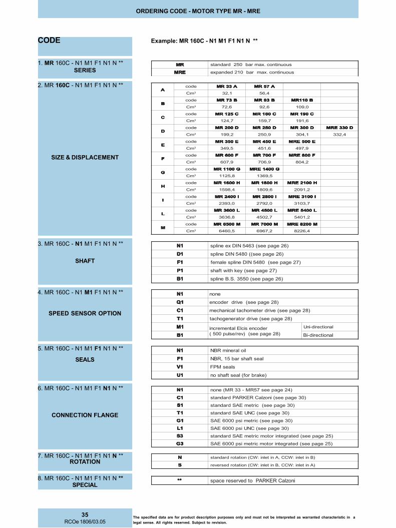
35RCOe 1806/03.05
The specified data are for product description purposes only and must not be interpreted as warranted characteristic in a
legal sense. All rights reserved. Subject to revision.
ORDERING CODE - MOTOR TYPE MR - MRE
CODE Example: MR 160C - N1 M1 F1 N1 N **
RMRMRMRMRM suounitnoc.xamrab052dradnats
ERM ERM ERM ERM ERM suounitnoc.xamrab012dednapxe
1. MR 160C - N1 M1 F1 N1 N **
1N1N1N1N1N )62egapees(3645NIDxeenilps
1D1D1D1D1D )62egapees((0845NIDenilps
1F1F1F1F1F )72egapees(0845NIDenilpselamef
1P1P1P1P1P )72egapees(yekhtiwtfahs
1B1B1B1B1B )62egapees(0553.S.Benilps
3. MR 160C - N1 M1 F1 N1 N **
1N1N1N1N1N enon
1Q1Q1Q1Q1Q )82egapees(evirdredocne
1C1C1C1C1C )82egapees(evirdretemohcatlacinahcem
1T1T1T1T1T )82egapees(evirdrotarenegohcat
1M1M1M1M1M redocnesiclElatnemercni
)82egapees()ver/eslup005(
lanoitcerid-inU
1B1B1B1B1B lanoitcerid-iB
4. MR 160C - N1 M1 F1 N1 N **
1N1N1N1N1N liolarenimRBN
1F1F1F1F1F laestfahsrab51,RBN
1V1V1V1V1V slaesMPF
1U1U1U1U1U )ekarbrof(laestfahson
5. MR 160C - N1 M1 F1 N1 N **
NNNNN )Bnitelni:WCC,Anitelni:WC(noitatordradnats
SSSSS )Anitelni:WCC,Bnitelni:WC(noitatordesrever
7. MR 160C - N1 M1 F1 N1 N **
1N1N1N1N1N )42egapees75RM-33RM(enon
1C1C1C1C1C )03egapees(inozlaCREKRAPdradnats
1S1S1S1S1S )03egapees(cirtemEASdradnats
1T1T1T1T1T )03egapees(CNUEASdradnats
1G1G1G1G1G )03egapees(cirtemisp0006EAS
1L1L1L1L1L )03egapees(CNUisp0006EAS
3S3S3S3S3S )52egapees(detargetnirotomcirtemEASdradnats
3G3G3G3G3G )52egapees(detargetnirotomcirtemisp0006EAS
6. MR 160C - N1 M1 F1 N1 N **
********** inozlaCREKRAPotdevreserecaps8. MR 160C - N1 M1 F1 N1 N **
SERIES
SIZE & DISPLACEMENT
SHAFT
SPEED SENSOR OPTION
SEALS
CONNECTION FLANGE
ROTATION
SPECIAL
AAAAAedoc A33RM A33RM A33RM A33RM A33RM A75RM A75RM A75RM A75RM A75RM
mC 3 1,23 4,65
BBBBBedoc B37RM B37RM B37RM B37RM B37RM B39RM B39RM B39RM B39RM B39RM B011RM B011RM B011RM B011RM B011RM
mC 3 6,27 6,29 0,901
CCCCCedoc C521RM C521RM C521RM C521RM C521RM C061RM C061RM C061RM C061RM C061RM C091RM C091RM C091RM C091RM C091RM
mC 3 7,421 7,951 6,191
DDDDDedoc D002RM D002RM D002RM D002RM D002RM D052RM D052RM D052RM D052RM D052RM D003RM D003RM D003RM D003RM D003RM D033ERM D033ERM D033ERM D033ERM D033ERM
mC 3 2,991 9,052 1,403 4,233
EEEEEedoc E053RM E053RM E053RM E053RM E053RM E054RM E054RM E054RM E054RM E054RM E005ERM E005ERM E005ERM E005ERM E005ERM
mC 3 5,943 6,154 9,794
FFFFFedoc F006RM F006RM F006RM F006RM F006RM F007RM F007RM F007RM F007RM F007RM F008ERM F008ERM F008ERM F008ERM F008ERM
mC 3 9,706 9,607 2,408
GGGGGedoc G0011RM G0011RM G0011RM G0011RM G0011RM G0041ERM G0041ERM G0041ERM G0041ERM G0041ERM
mC 3 8,5211 5,9631
HHHHHedoc H0061RM H0061RM H0061RM H0061RM H0061RM H0081RM H0081RM H0081RM H0081RM H0081RM H0012ERM H0012ERM H0012ERM H0012ERM H0012ERM
mC 3 4,8951 6,9081 2,1902
IIIIIedoc I0042RM I0042RM I0042RM I0042RM I0042RM I0082RM I0082RM I0082RM I0082RM I0082RM I0013ERM I0013ERM I0013ERM I0013ERM I0013ERM
mC 3 0,3932 0,2972 7,3013
LLLLLedoc L0063RM L0063RM L0063RM L0063RM L0063RM L0054RM L0054RM L0054RM L0054RM L0054RM L0045ERM L0045ERM L0045ERM L0045ERM L0045ERM
mC 3 8,6363 7,2054 2,1045
MMMMMedoc M0056RM M0056RM M0056RM M0056RM M0056RM M0007RM M0007RM M0007RM M0007RM M0007RM M0028ERM M0028ERM M0028ERM M0028ERM M0028ERM
mC 3 5,0646 2,7696 4,6228
2. MR 160C - N1 M1 F1 N1 N **

36RCOe 1806/03.05
The specified data are for product description purposes only and must not be interpreted as warranted characteristic in a
legal sense. All rights reserved. Subject to revision.
The specified data are for product description purposes only and must not be interpreted as warranted characteristic in a legal sense.
All rights reserved. Subject to revision.
SALES AND SERVICE LOCATIONS WORLDWIDE - MOTOR TYPE MR - MRE
FOR INFORMATION ABOUT SALES AND SERVICE LOCATIONS PLEASE CONTACT:
Parker Calzoni S.r.l.
Via caduti di sabbiuno 15/17
40011 Anzola dell’Emilia
Bologna – Italy
Tel. +39.051.6501611
Fax. +39.051.736221e-mail: [email protected]
YOUR LOCAL PARKER CALZONI REPRESENTATIVE
www.parker.com
![Civil MCQ edit - Civil Engineering Objectivecivilengineeringmcq.com/wp-content/uploads/2017/12/Hydraulics.pdf+\GUDXOLFV )OXLG 0HFKDQLFV Y µ ] } v E } X ì í t Z v } Ç ] o } À o](https://static.documents.pub/doc/80x56/60e266543a29d3414b16d895/civil-mcq-edit-civil-engineering-objectiv-gudxolfv-oxlg-0hfkdqlfv-y-.jpg)


