

Guide Elements
D2 subject to alterations
The great importance of exact alignment
between punches and matrices in stamping
dies has been recognized widely. The accuracy
and maintenance of this alignment depends
entirely on the quality and wear resistance of
the guide elements.
As a consequence of recent rapid developments
in stamping techniques it has also been
accepted that conventional bush-pillar sets of
casehardened steel can no longer stand up to
the demands of the modern press shop with its
more sophisticated dies, ever faster presses and
the stresses in today’s carbide tools.
The introduction of FIBRO Guide Elements
made available an extensive range, principally
based on superlative quality, and comprising
some new, highly advanced bearing materials
as well as novel assembly techniques of
superior accuracy.
Recent additions have further broadened this
range, especially in regard of demountable
guiding components.
All FIBRO Guide Bushes for permanent fixing
are laid out for epoxy-bonding. This highly
reliable method ensures unparalleled accuracy
together with the elimination of shrink
allowances and rectification honing.
Ball Bearing Guides principally excel in
undemanding maintenance and through the
complete absence of bearing play. Their easy
movement on the bench makes them very
popular with die makers. Highest stroking
speeds present no problems. But common to all
ball bearings there remains the characteristic
weakness to shock loads, the danger of ball
impingement. To some extent this can be
compensated for by oversized pillar diameters
and the use of four-pillar die sets.
The group of Sliding-Type Guides affords much
greater stability, partly due to the damping
effect of the all-important, vital oil film . . .
which in the past used to be threatened always
by the vagaries of lubrication service and the
propensity to rupture at high frequencies of
travel reversal.
Extensive protection against these perils is
offered by FIBRO Sintered Ferrite Bushes. Used
in most of our sliding guide systems, their
advanced technology comprises:
– porous structure, vacuum-filled with oil
– carbonitrided surface of extreme hardness
– outstanding friction properties
– exceptional wear-resistance
– thousands of oil-retaining porosity pockets.
In combination with our mirror-finished pillars,
ferrite guide bushes represent a guiding system
of alltogether superior properties. A system
that virtually precludes seizing under all but
the most extreme running conditions.
Beyond such limitations there exist
combinations of high velocities with very short
strokes where even ferrite bushes cannot
guarantee permanence of the oil film.
Here, the rigidity of the sliding guide has to be
weighed up against the safety of ball bearings:
die set guides are not entirely without
problems yet! But at FIBRO we find ourselves
very busy indeed with the remainder.
Technical progress may incur modifications
without notice.
FIBRO GUIDE ELEMENTS – DESIGNED
AND PRODUCED BY PEOPLE IN PURSUIT OF
PERFECTION.
Guide Elements

subject to alterations
Centering unit with adjusting washer
Material:Centring Units: 16MnCr5, heat treatedConical surfaces induction hardenedSurface hardness: 60 + 4 HRC, Eht: 1,0 + 0,5 mmAdjusting washer: C45 or similar
Note:Centring unit complete with adjusting washer.Screws are included.
2441.11.0.'''Centring unit with adjusting washer
2441.11.0.'''.1Centring unit with one flat side with adjusting washer
2441.11.0.'''.2Centring unit with two flat sides with adjusting washer
ø16
20
l 2
±0
,05
l
16
M5
l 1
15
15
H7
H7ø16
ø11M12
ø11
d3
d1
d2
d5
k*/
2
k*
k* = d3
k*/2 = d3/2
2441.11.0.
D256
Order No d1 d2 d3 l l1 l2 d52441.11.0.100 100 76 58 80 40 55 40.52441.11.0.100.1 100 76 58 80 40 55 40.52441.11.0.100.2 100 76 58 80 40 55 40.52441.11.0.120 120 96 78 90 50 65 50.52441.11.0.120.1 120 96 78 90 50 65 50.52441.11.0.120.2 120 96 78 90 50 65 50.5
2441.11.0. Centering unit with adjusting washer

subject to alterations
Centering unit15
15 20
M5
16
H7ø16ø11
H7ø16
k*/2
k*
k* = d3
k*/2 = d3/2
ø11M12
d3
d1
d2
d5
l 2±0
,05
l
l 1
2441.11.
Material:16MnCr5, heat treatedConical surfaces induction hardenedSurface hardness: 60 + 4 HRC, Eht: 1,0 + 0,5 mm
Note:Adjusting washer 2441.11.3. to be ordered separately.Screws are not included.
2441.11.(((Centring unit
2441.11.(((.1Centring unit with one flat side
2441.11.(((.2Centring unit with two flat sides
D257
Order No d1 d2 d3 l l1 l2 d52441.11.100 100 76 58 80 40 55 40.52441.11.100.1 100 76 58 80 40 55 40.52441.11.100.2 100 76 58 80 40 55 40.52441.11.120 120 96 78 90 50 65 50.52441.11.120.1 120 96 78 90 50 65 50.52441.11.120.2 120 96 78 90 50 65 50.5
2441.11. Centering unit

subject to alterations
Adjusting washer
Material:C45 or similar
Note:2441.11.3.&&&Adjusting washer
2441.11.3.&&&.1Adjusting washer with one flat side
2441.11.3.&&&.2Adjusting washer with two flat sides
d5
d1
d2
+0
.1
dø11
k*/2
k*
k* = d3
k*/2 = d3/2
c
2441.11.3.
D258
Order No d1 d2 d4 c d5 k2441.11.3.100 100 76 17 9.8 40.5 582441.11.3.100.1 100 76 17 9.8 40.5 582441.11.3.100.2 100 76 17 9.8 40.5 582441.11.3.105 105 76 18 5.5 40.5 582441.11.3.120 120 96 17 9.8 50.5 782441.11.3.120.1 120 96 17 9.8 50.5 782441.11.3.120.2 120 96 17 9.8 50.5 782441.11.3.125 125 96 18 5.5 50.5 78
2441.11.3. Adjusting washer

subject to alterations
Centring unit, CNOMO
ø18,5
120°
(3x)
3d2d
d5
M10ø10 G6(2x) H13ø13 (3x)
d2
d6
d5
0,5h1
h3
0,5
d1
ø11ø18
H13ø13ø10(2x) (3x)
G6
h2
22
22
4d
±0
,25
l()
15
2441.13.45.
Material:X153CrMoV12 (1.2379), hardened 58 ± 2 HRC
Note:Order No for centring unit to CNOMO with adjusting washer: 2441.13.0.45.Screws and pins are not included.
D259
Order No d1 d2 d3 d4 d5 d6 h1 h2 h3 l2441.13.45.040 40 90 69 45 50 67 36 61 61 (86)2441.13.45.060 60 110 89 65 70 89 46 61 61 (86)
2441.13.45. Centring unit, CNOMO

subject to alterations
Adjusting washer, CNOMO
Material:Cf 70 (1.1249)
Note:Adjusting washer for centring unit 2441.13.45.
5
120°
(3x)
d1
d 2
d 3 ø14(3x)ø12(2x)
2441.13.3.45.
D260
Order No d1 d2 d32441.13.3.45.040 40 90 672441.13.3.45.060 60 110 89
2441.13.3.45. Adjusting washer, CNOMO

subject to alterations
Centring unit, CNOMO
G8ø10(2x)
22
22
15
ø19
M10
d2
d3
d4
d6
d5
ø11
h3
h1
h2
±0
,25
l()
d 18H13ø13
(3x)
1
2441.13.
Material:16MnCr5, heat treatedConical surfaces induction hardenedSurface hardness: 60 + 4 HRC, Hardness penetration 1,0 + 0,5 mm
Note:Order No for centring unit to CNOMO with adjusting washer: 2441.13.0.Screws and pins are not included.
D261
Order No d1 d2 d3 d4 d5 d6 h1 h2 h3 (l)2441.13.040 40 100 79 50 90 67 36 61 28 (86)2441.13.060 60 125 104 70 110 89 46 61 18 (86)
2441.13. Centring unit, CNOMO

subject to alterations
Adjusting washer, CNOMO
Material:100 Cr 6
Note:Adjusting washer for centring unit 2441.13.
3x120°
d2
d3
5
ø12 (2x) ø15 (3x)
d 1
2441.13.3.
D262
Order No d1 d2 d32441.13.3.040 40 90 672441.13.3.060 60 110 89
2441.13.3. Adjusting washer, CNOMO

subject to alterations
Centring pin
3
R3
2445.10.
Description:Using locating holes components, assemblies and tools can be repeatedly centred with high precision on processing machines, measuring equipment and tool components.
Material:Steel, hardened
Note:Screws are not included.1) to BMW standard2) to VW standard
Fixing:Use socket cap screws DIN EN ISO 4762 M6/M8.
20
+min.1
1d
H7
1d
25
Mounting example Mounting example
D263
Order No d1 d2 d3 l1 l2 l3 r12445.10.022.045 1), 2) 22 21.95 M8 45 16 35 152445.10.022.055 2) 22 21.95 M8 55 16 45 152445.10.032.050 1) 32 31.95 M10 50 20 35 202445.10.040.055 1), 2) 40 39.95 M10 55 20 35 252445.10.040.065 2) 40 39.95 M10 65 20 45 252445.10.050.055 1) 50 49.95 M10 55 20 35 252445.10.056.080 1) 56 55.95 M10 80 20 60 30
2445.10. Centring pin

subject to alterations
Centring pin to Mercedes-Benz standard
Description:Using locating holes components, assemblies and tools can be repeatedly centred with high precision on processing machines, measuring equipment and tool components.
Material:Steel, hardened
Note:Screws are not included.
Fixing:Use socket cap screws DIN EN ISO 4762 M6/M8.
H7d
25
50
15°
3d
4d
1d
j6d
2d
51t
t2
x45
°
8
2445.11.
Mounting example Mounting example
D264
Order No d d1 d2 d3 d4 t t12445.11.022 22 11 M8 9 16 13 162445.11.025 25 11 M8 9 18 13 162445.11.032 32 11 M8 9 25 13 162445.11.040 40 15 M10 11 32 16 202445.11.050 50 15 M10 11 42 16 20
2445.11. Centring pin to Mercedes-Benz standard

subject to alterations
Pressure bolt with base, according to VW
32,5
65
R20
20
12
20
65
ø13
ø36 +2
ø16-0,1-0,3
ø90 ±1
65
20
ø20
1x45°
±0,05
*l
1x45°
50 -2
40
R8 +2
20
R8 +2
R8 +2
2446.10.55.03.
2446.10.55.02.
2446.10.55.04.
2446.10.55.05.
Description:Pressure bolts with base are used to transfer force from the pressure cushion of the press to the tool.
Material:C45 (1.0503), heat-treated 800 - 1000 N/mm2
Execution:drop-forged
Note:Screws are not included.
06.2015
Order No l*Gradation
l2446.10.55.02. 150 - 360 12446.10.55.03. 150 - 360 12446.10.55.04. 150 - 360 12446.10.55.05. 150 - 360 1*to customer’s specifications!
Ordering Code (example):Pressure bolt with base, according to VW =2446.10.55.Execution Shape 4 = 04.Length 150 mm= 150Order No =2446.10.55. 04. 150
2446.10.55. Pressure bolt with base, according to VW

subject to alterations
Air pin, according to VW standard
Description:Air pins are used to transfer force from the pressure cushion of the press to the tool.
Material:C45 (1.0503), heat-treated 800 - 1000 N/mm2
Execution:drop-forged
Note:Screws are not included.
2012
ø60 +2
ø110 ±1
ø20
ø13
ø16-0,1-0,3
±0
,1*l
2x45
°
1x45
°
5
R3
35
3x120°
ø85
3x120°
ø85
2446.11.55.01.
2446.11.55.02.
06.2015
Order No l*Gradation
l2446.11.55.01. 150 - 440 12446.11.55.02. 150 - 440 1*to customer’s specifications!
Ordering Code (example):Air pin, according to VW standard =2446.11.55.Execution Shape 2 = 02.Length 150 mm= 150Order No =2446.11.55.02. 150
2446.11.55. Air pin, according to VW standard

subject to alterations
Concertina shroud with spacer bush
1lm
ax.
a1a
i
3daD
D
2d1d
l min
.l
206.91.
Note:Concertina Shrouds are supplied complete with spacer bush and two hose clamps.Special sizes on request.
Mounting example
D265
for guide bushes
2051./2061.
2051./2061.
2051./2061.
2051./2061.
2051./2061.
2051./2061.
2051./2061. 2081. 2081. 2081. 2081. 2081. 2081. 2081.
Pillar-ø d1 19 20 24 25 30 32 38 40 48 50 60 63 19 20 24 25 30 32 38 40 48 50 60 63d* 20 25 32 40 50 60 63 20 25 32 40 50 60 63d2 25 30 40 50 60 70 70 25 30 40 50 60 70 70d3 32 38 46 55 64 76 76 39 45 54 63 74 94 94d4** 32 38 48 58 58 79 79 40 45 54 66 80 95 95Di 30 30 46 55 62 75 75 32 32 45 52 62 75 75Da 51 56 72 87 86 100 100 54 56 63 96 84 104 104a 13 13 20 12 12 12 12 10 10 10 12 12 10 10a1 16 13 20 12 12 10 10 10 10 10 12 12 10 10l1 20 30 30 40 40 40 40 20 30 30 40 40 40 40lmin 30 25 20 44 25 30 30 37 35 35 25 45 35 35lmax 170 130 100 119 110 130 130 145 110 110 225 165 185 185*d = Nominal diameter, **d4 = Nominal ordering diameter for flange diameter
Ordering Code (example):Concertina shroud with spacer bush =206.91.Nominal diameter d 20 mm= 020.Nominal ordering diameter for flange diameter d4 40 mm= 040Order No =206.91. 020.040
206.91. Concertina shroud with spacer bush

subject to alterations
Spacer bushSpacer tube
Material:PMMA, PLEXIGLAS®
Material:PMMA, PLEXIGLAS®
1l
1d2d
206.93.
100
1d2d
206.94.
D266
Ordering Code (example):Spacer bush =206.93.Nominal diameter d 40 mm = 040Order No =206.93. 040
Ordering Code (example):Spacer tube =206.94.Nominal diameter d 40 mm = 040Order No =206.94. 040
Pillar-ø d1 15 16 19 20 24 25 30 32 38 40 48 50 60 63d* 16 20 25 32 40 50 60 63d2 20 25 30 40 50 60 70 70l1 20 20 30 30 40 40 40 40*d = Nominal diameter
Pillar-ø d1 15/16 19/20 24/25 30/32 38/40 48/50 60 63d* 16 20 25 32 40 50 60 63d2 20 25 30 40 50 60 70 70l1 100 100 100 100 100 100 100 100*d = Nominal diameter
206.93.
206.94.
Spacer bush
Spacer tube

subject to alterations
Concertina shroud with spacer tube
D
100
d1d
a
3dD
2
a1a
max
.l m
in.
l
i
206.92.
Note:Concertina Shrouds are supplied complete with spacer tube and two hose clamps.Special sizes on request.
Mounting example
D267
for guide bushes
2051./ 2061.
2051./2061.
2051./2061.
2051./2061.
2051./2061.
2051./2061.
2051./2061. 2081. 2081. 2081. 2081. 2081. 2081. 2081.
Pillar-ø d1 19 20 24 25 30 32 38 40 48 50 60 63 19 20 24 25 30 32 38 40 48 50 60 63d* 20 25 32 40 50 60 63 20 25 32 40 50 60 63d2 25 30 40 50 60 70 70 25 30 40 50 60 70 70d3 32 38 46 55 64 76 76 39 45 54 63 74 94 94d4** 32 38 48 58 58 79 79 40 45 54 66 80 95 95Di 30 30 46 55 62 75 75 32 32 45 52 62 75 75Da 51 56 72 87 86 100 100 54 56 63 96 84 104 104a 13 13 20 12 12 12 12 10 10 10 12 12 10 10a1 16 13 20 12 12 10 10 10 10 10 12 12 10 10l1 100 100 100 100 100 100 100 100 100 100 100 100 100 100lmin 30 25 20 44 25 30 30 37 35 35 25 45 35 35lmax 170 130 100 119 110 130 130 145 110 110 225 165 185 185*d = Nominal diameter, **d4 = Nominal ordering diameter for flange diameter
Ordering Code (example):Concertina shroud with spacer tube =206.92.Nominal diameter d 20 mm= 020.Nominal ordering diameter for flange diameter d4 40 mm= 040Order No =206.92.020.040
206.92. Concertina shroud with spacer tube

subject to alterations
Helical spring for ball cage retention
Calculation:Formula for selecting spring 241.18.:FL = [l - (l2 + (l1 - l3))] x 1,1Formula for calculating the block length LBL of the selected spring:LBL = ( l0 x d : s) + 2 x dFL = Length of compressed springl = Length of guide pillar (Customer specified)l1 = Cage length (Customer specified)l2 = Compression length of guide pillar (Customer specified)l3 = Ball cage retainer size (Customer specified)1.1 = Safety factorl0 = Length of uncompressed springd = Spring wire diameters = Pitch
Without ball cage
retainer
With ball cage
retainer
202.91.
With ball cage
retainer
202.91.
3l
1l
2ll L
F
Without ball cage
retainer
With ball cage
retainer
202.92.1.
With ball cage
retainer
202.92.1.
ø pillar d₁
ds
0l
2d
3d241.18.
Mounting example Mounting example
D268
d1 d2 d3 s d l0 Gradation l019/20 20.5 22.5 14 1 40 - 140 1024/25 25.5 27.9 14 1.2 40 - 160 1030/32 32.5 35.7 16 1.6 50 - 230 1038 38.5 42.5 18 2 60 - 230 1040 40.5 45.1 20 2.3 60 - 230 1048/50 50.5 55.7 20 2.6 70 - 280 1060 60.5 66.9 20 3.2 80 - 250 1063 63.5 69.9 20 3.2 80 - 250 10
Ordering Code (example):Helical spring for ball cage retention =241.18.Inside diameter d2 40.5 mm = 405.Length l0 60 mm = 060Order No =241.18. 405. 060
241.18. Helical spring for ball cage retention

subject to alterations
Cage retainer
2
d
M6
DIN EN ISO
4762
202.91.
Note:The following guide pillars can be equipped with this cage retainer.Guide pillars without cage retainer -
become guide pillars with cage retainer:
202.19. - 202.17.202.21. - 202.55.2021.46. - 2021.44.2021.50. - 2021.58.
2
d
4l
min
.
20
1
l
15
ø10
+0,1
ø17
M6
1
d
Mounting example
D269
d1 38 40 48 50 60 63d2 42 44 52 54 64 67KG (l / l1)1 (31 / 46) + + + + + +2 (41 / 56) + + + + + +3 (51 / 66) + + + + + +4 (61 / 76) + + + + + +5 (73 / 89) + + + + + +
Ordering Code (example):Cage retainers =202.91.Guide diameter d1 50 mm= 050.Cage retainer size KG 1 = 1Order No =202.91. 050.1
202.91. Cage retainer

subject to alterations
Cage retainer
Note:The following guide pillars can be equipped with this cage retainer:202.22.202.24.2021.46.2021.50.
3
l
l
2
ca
ge
tra
ve
l
stro
ke
2
=
2
202.92.1
1
d
1
l
order separately:
206.75. Ball Cage
2060.65. Ball Cage
202.92.1.
8
2
d
M8
2
f
Mounting example
10.2014
d1 19 20 24 25 30 32 38 40 48 50 60 63d2 18 19 23 24 29 31 37 39 47 49 59 62f 22 23 27 28 34 36 42 44 52 54 64 67
Ordering Code (example):Cage retainer =202.92.1.Guide diameter d1 38 mm = 038Order No =202.92.1. 038
202.92.1. Cage retainer
subject to alterations
Springs for dies, fixtures, moulds,
machines, mechanisms. For various
industrial uses.
FIBRO Compression Springs – a comprehensive
range, rooted in the resolute quality consci-
ousness on which our reputation was built.
Applied equally to the selection and inspecti-
on of raw materials as well as to every step in
manufacture.
Springs – a simple product by comparison. But
a demanding one also if new standards are to
be set by its reliability and performance.
A product whose failure in service always is
very expensive, even disastrous in some cases.
A product therefore where it pays . . . to pay for
the difference. Whose faults or qualities remain
hidden at first. They prove themselves in the
long run –!
FIBRO high performance springs – in four
duty ranges. Made from selected grades of
chrome-vanadium spring steel.
Cold-formed from special rolled wire sections.
Capable of sustaining service loadings of
exceptional serverity.
Identical fitting dimensions for all springs of
common nominal size, facilitating development
work. Packing a maximum of spring action into
a minimum of design space
Up and down in endless repetition: FIBRO Com-
pression Springs. From the tough stable of tool-
and diemaking, where no quarters are given.
A spring range of almost 400 sizes. Each spring
strictly to specification. Ends flattened and
ground parallel. Surfaces ball shot peened for
even greater spring resilience.
FIBRO Springs – for fit-and-forget performance.
For confined spaces. For virtually no space at
all. For aircraft · tractors · harvesters · dies jigs ·
fixtures · for machines from A to Z.
For all uses where the going is hard. A choice
without regrets.
A special spring range for demanding
applications in the manufacture of tools,
machinery and jigs & fixtures.
Our spring systems are constantly being
developed to cover the most varied
requirements.
The spring type is selected to match specific
customer requirements.
Special helical springs
Manufactured to DIN ISO 10243, the springs
are available in four grades for high cyclic and
constant loads.
The specially rolled wire profile is manufactured
from high quality heat treated alloy steel.
FIBROFLEX® Springs
These rubber-elastic spring elements in Sho-
rehardness ratings 80, 90, 95, are made from
polyurethane elastomers. Benefits include
high spring forces and good resilient damping
behaviour.
FIBROELAST® Springs
As a superior alternative to rubber springs we
offer polyurethane elastomer springs in Shore A
hardness rating of 70.
Disc Springs
The required spring characteristics result from
various laminations with multiple settings and
combinations.
FIBRO Gas springs
close a gap where ever the accent is on accomo-
dation of the utmot force component within a
minimum of space – or where exceedingly large
travel is demanded: FIBRO Gas springs take care
of both demands, even in combination.
Springs

subject to alterations
Cage retainer
9
3d
2d
ø9
ø15
1l
2l
cag
e tr
avel
= s
tro
ke/2
202.93.
Note:The following guide pillars can be equipped with this cage retainer:202.22.202.24.2021.46.2021.50.
Screws are not included.
Fixing:Use socket cap screws DIN EN ISO 4762 for ordering size:03. - 2192.12.08.03504. - 2192.12.08.04505. - 2192.12.08.05506. - 2192.12.08.07008. - 2192.12.08.090
ca
ge
tra
ve
l =
str
ok
e 1
/2
2l
3
1d
2d
d
M8
1l
202.93.
Mounting example
D271
Order No d1 d2 d3 l1 l2202.93.03.030 30 o.32 36 23 30 6202.93.04.040 38 o. 40 44 31 40 6202.93.05.050 48 o. 50 54 39 50 8202.93.06.060 60 o. 63 66 51 60 8202.93.08.080 80 89 71 80 8
202.93. Cage retainer

subject to alterations
Pillar wiper
Description:FIBRO Pillar Wipers protect against premature wear caused by the ingress of dirt into the die set guides.Outside diameters match boss dias. on FIBRO Die Sets (Cast Iron). They can be fitted onto the bolster, or into a counterbore – flush with the bolster surface.
Note:Pillar Wipers will be delivered with 3 screws M 4 × 16 DIN 963.
8,5
3d
1d
2d
206.95.2061.95.
Mounting example
D272
Order No d1 d2 d3206.95.024 24 45 55206.95.025 25 45 55206.95.030 30 55 65206.95.032 32 55 65206.95.038 38 65 75206.95.040 40 65 75206.95.042 42 65 75206.95.048 48 78 94206.95.050 50 78 94206.95.052 52 78 94206.95.060 60 92 110206.95.063 63 92 1102061.95.024 24 50 602061.95.025 25 50 60
206.95./2061.95. Pillar wiper

subject to alterations
Lifter pin for press tool strips
10
3
8
h61d
3d
2d
4d
hD
31l
244.00.2.
Description:Combination progression dies with certain forming stages can be equipped advantageously with springloaded lifter pins. FIBRO Lifter Pins 244.00.2., available in four sizes, can be used to assume the double function of lifting and guiding the strip. The amount of lift is a function of the counterbore-depth.
Material:1.7131, case-hardened
Execution:ground
Note:For ordering code of screw plug 241.00.1. and helical spring see spring range on pages chapter F.
Mounting example
D273
d1 8 10 13 16d2 5 6 7 8d3 10 12 16 20Dh 10.5 12.5 16.5 20.5d4 M12x1.5 M14x1.5 M18x1.5 M22x1.5l120 +25 + + +32 + + + +40 + + + +50 + + +
Ordering Code (example):Lifter pin for press tool strips =244.00.2.Guide diameter d1 13 mm = 13.Guide length l1 25 mm = 025Order No =244.00.2.13. 025
244.00.2. Lifter pin for press tool strips

subject to alterations
Screw clamp with screw
15
8,7
6 8,5
13
207.45
7
19
,5
11
5,8
+0
,1
ø7
ø16
ø11
ø23
2071.45
7,5
11
32
5
10
10
32
3
6,3
20
5
20
10
16
2072.45.10. 2072.45.16.
Screw clampincl. screw- steel punched bent
component- clamping height 6-6,3 mm
- M6 screw
Screw clampincl. screw- clamping height 6 mm- M6 screw
Screw clampincl. screw2072.45.10- Steel, milled- clamping height 6-6,3 mm
- M6 screw2072.45.16- Steel, milled- clamping height 10 mm- M10 screw
D274

subject to alterations
Screw clamp with screwScrew clamp with screw, GM StandardScrew clamp with screw, NAAMS
Screw clampincl. screw- Steel, milled- clamping height 6-6,3 mm
- M10 screw
Screw clampaccording to GM, incl. screw2072.46.30.12- Steel, milled- clamping height 6 mm- M8 screw2072.46.30.16- Steel, milled- clamping height 6 mm- M10 screw
Screw clampaccording to NAAMS, incl. screw- steel punched bent
component- clamping height 6-6,3 mm
- M8 screw
6
113
2
5
10
32
16
2072.46
ø11,5ø9
11,5
8,5
105
21
25 32
15
20
25
ø15 ø18
12
16
6-0,3
0,5
+0,5
6-0,3
0,5
+0,5
2072.46.30.12 2072.46.30.16
13,5
18,9
24,6
5
6 13
2072.47
D275

subject to alterations
Securing flange with screws, CNOMOScrew clamp with screw, CNOMO
Securing flangeaccording to CNOMO, incl. screws- steel, turned- clamping height 4, 5, 6, 8, 10, 12, 16, 20 mm- M6, M8, M10, M12 screws
Screw clampaccording to CNOMO, incl. screw- Steel, milled- clamping height 8, 10, 12, 16, 20 mm- M6, M8, M10 screw
e1
4d
e2
e3
5
3l h
3d
5d
6d
d1G7
d2M6m6 M
A A
„ A “
2073.45.
m
pm
kt
e
n3d
2d
A A
„ A “
2072.48.45.
D276
Order No d1 d2 d3 d4 d6 h l3 e1 e2 e3 M2073.45.020 20 28 32 63 25 10 4 16 18 - 6x162073.45.025 25 35 40 72 32 10 5 20 20 - 6x162073.45.032 32 44 50 80 40 12 6 25 21 - 6x162073.45.040 40 52 60 100 50 12 8 38.5 14 41 6x162073.45.050 50 63 71 125 63 16 10 46 17 49 8x202073.45.063 63 80 90 140 80 20 12 55 17 57.5 10x252073.45.080 80 100 112 180 100 25 16 70 20 72 12x302073.45.100 100 125 140 200 125 32 20 81 25 85 12x30
Order No k e d2 d3 t m p n d1 M2072.48.45.12 12 8 11 6.6 6.8 18 9.5 15.5 40 6x162072.48.45.16 16 10 15 9 9 22 12 19 50 8x202072.48.45.20 20 12 18 11 11 26 15 21 63 10x252072.48.45.25 25 16 18 11 11 26 15 21 80 10x302072.48.45.32 32 20 18 11 11 26 15 21 100 10x35
2073.45.
2072.48.45.
Securing flange with screws, CNOMO
Screw clamp with screw, CNOMO

subject to alterations D277

subject to alterations
Spacer plate toothed, with adjusting plate
Material:Spacer plates: X 210 Cr 12 (1.2080), hardened 58 + 2 HRCAdjusting plate: X 153 CrMoV 12 (1.2379)
Description:For spacing out sheet metal retainers in tools for external skin parts.
Note:Screws are not included.
'0'= basic setting in the middle (grinding-in)'+'= adjustment to the right - plus'-' = adjustment to the left - minus
NB: Hole patternThe bolsters are reversible.
Adjustment range:2444.1212 increments each of 0.02 mm means an adjusting range of 0.24 mm with a minimum support area of 80 x 60 mm.2444.1314 increments each of 0.02 mm means an adjusting range of 0.28 mm with a minimum support area of 100 x 80 mm.
11
M10
20
11
5
0°14
'13
"
l 2
l 3
H H1
35
0
0
l 1
21
4
35
ø18
ø11
M10x20 DIN EN ISO 4762
M10x20DIN EN ISO 4762
A - A
l 4l 5l 6l 7
18
b1
b
AA
11 21
ø18
ø11
Basis: 0.02 mm per tooth
M10x20DIN EN ISO 4762
2444.12 / 2444.13
D278
Order No l1 l2 l3 l4 l5 l6 l7 b b1 H H12444.12 130 90 130 61 72 79 90 60 30 15.5 16.042444.13 160 110 160 71 82 89 120 80 40 15.5 16.16
2444.12/2444.13 Spacer plate toothed, with adjusting plate

subject to alterations
Guide
ø8 +0,1
13
,5 1,5
8
min.ø40
ø30
20°
13
R20
107
M12
20
l
30
2626
R10
Rounded transition R5
2443.10.
Material:Ck 60, hardened 58 + 2 HRC
Execution:forged
D279
Order No l2443.10.065 652443.10.090 902443.10.120 1202443.10.150 1502443.10.180 1802443.10.250 2502443.10.300 3002443.10.350 350
2443.10. Guide

subject to alterations
Guide to Mercedes-Benz Standard - unhardened
Material:Ck 60
Execution:forged
Note:Guides are preferably used in confined spaces in sequential compound dies.
54,5
63
73
20
15
l
9
1,5
10
min.ø30
M8
R10
R20
ø20
20°
ø6,1
27,5
15
Rounded transition R5
2443.10.20.
D280
Order No l2443.10.20.065 652443.10.20.090 90
2443.10.20. Guide to Mercedes-Benz Standard - unhardened

subject to alterations
Guide to Mercedes-Benz Standard - hardened
54,5
63
73
20
15
l
9
1,5
10
min.ø30
M8
R10
R20
ø20
20°
ø6,1
27,5
15
Rounded transition R5
2443.10.20. .1
Material:Ck 60, hardened 58 + 2 HRC
Execution:forged
Note:Guides are preferably used in confined spaces in sequential compound dies.
D281
Order No l2443.10.20.065.1 652443.10.20.090.1 90
2443.10.20. .1 Guide to Mercedes-Benz Standard - hardened

subject to alterations
Guide with part position control and spring
2018.00.60.08.030
Mounting example
Material:Guide: Ck 60, hardened 50 + 5 HRCFlap: St 37Spring: Spring steel wire
Execution:forged
Note:See following pages for accessories.
Roundedtransition R5
30
20
107
l
l 1l 2
8
ø6,5
4010
58
R4,5Thickness8mm
Version with short flap:l = 120, 150 mm
1)
15°
4010
ø6,5
8
10
8
32
rounded
Thickness8mm
Version with long flap:l = 180, 250 mm
2)
M12
R10
13
20°
R20
ø8 +0,1
13
,5
8
2626
min.ø40
ø30
2443.12.
D282
Order No l l1 l22443.12.120 120 55 702443.12.150 150 55 702443.12.180 180 105 1202443.12.250 250 105 120
2443.12. Guide with part position control and spring

subject to alterations
Guide with part position control, VDI
M8x1
ø30
80°
40
10ø6,5 1
0
5x45
°
10
6130
ø6,2
27
16
,5
l
18
36
26
35
,5
108
Version with short flap:l = 120, 150 mm
1)
Version with long flap:l = 180, 250 mm
2)
100
20
7
28
M12
13
2
0
°
R
2
0
l
1
l
2
R
1
0
103
Rounded
transition R5
ø6
,2
5x45
°
30
x30
°
R
4
R
4
min.ø40
ø8 +0,1
13
,5 1,5
8
30
2626
2443.13.
Material:Guide: Ck 60, hardened 50 + 5 HRCFlap: St 37, hardened 58 + 2 HRC
Execution:forged
Note:See following pages for accessories
2018.00.60.08.030
Mounting example
D283
Order No l l1 l22443.13.120 120 55 702443.13.150 150 55 702443.13.180 180 105 1202443.13.240 240 105 120
2443.13. Guide with part position control, VDI

subject to alterations
Inductive proximity switch
Technical dataRated operating voltage Ue: 24 V DCOperating Voltage Us: 10-30 V DCNo load current I0 damped/undamped: ≤ 8 mA/≤ 1 mARepeat accuracy R: ≤ 5%Ambient temperature Ta: -40 to +85 °CSwitching frequency f: 3000 HzDegree of protection to IEC 529: IP 67Casing material: Stainless steelConnection: plug connectorApprovals: UL
2018.00.60.08.030
M8
x1
LED
19,5
30
A/F 13
D284
2018.00.60.08.030 Inductive proximity switch
subject to alterations
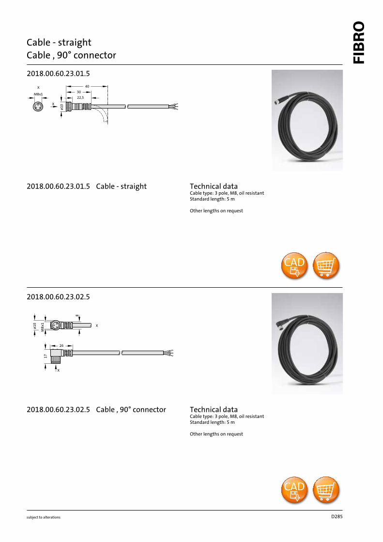
Cable - straightCable , 90° connector
2018.00.60.23.01.5
M8x1
X
ø10
30
22,5
40X
2018.00.60.23.02.5
ø10
M8
x1
X
17
8
26
X
Technical dataCable type: 3 pole, M8, oil resistantStandard length: 5 m
Other lengths on request
Technical dataCable type: 3 pole, M8, oil resistantStandard length: 5 m
Other lengths on request
D285
2018.00.60.23.01.5
2018.00.60.23.02. 5 Cable , 90° connector
Cable - straight

subject to alterations
Position monitor for boards
110
70
ø19
110
12
21
105
9
15
70
l
39
54
80
54,5
21
14,5
l
ø19
54
39
80
12
105
21 54,5
14,5
21
9
15
Shape A Shape B
2443.14.55.
Material:Steel
Note:See following pages for accessories.
Attention:At least two position monitors must be installed crosswise. In case of large parts, such as the side part, a third position monitor should be
placed. The position monitors should be placed in such a way that a perfect querying of the sheet metal part is guaranteed. Position moni-tors should be arranged a minimum of 5 mm away from the pulling or locking bards and not within the range of strong sheet movement.
2443.14.00.60.23.02.5
2443.14.00.60.23.01.5
2443.14.00.60.18.044
Mounting example
11.2014
Order No l Shape2443.14.55.01 145 A2443.14.55.02 145 B2443.14.55.03 185 A2443.14.55.04 185 B2443.14.55.25 225 A2443.14.55.26 225 B
2443.14.55. Position monitor for boards

subject to alterations
Inductive proximity switch
Technical data:Rated operating voltage Ue: 24 V DCOperating Voltage Us: 10-30 V DCNo load current I0 damped/undamped: ≤ 10 mA/≤ 3 mARepeat accuracy R: max. (% v. Sr) 5%Ambient temperature Ta: -25 to +70°CSwitching frequency f: max.1000 HzDegree of protection to IEC 60529: IP 67Casing material: CuZnConnection: plug connectorApprovals: UL
15
11
44,5
29,5
M18
x1
M12
x1
25 Nm 35 Nm
LEDSW24
2443.14.00.60.18.044
11.2014
2443.14.00.60.18.04 4 Inductive proximity switch
subject to alterations
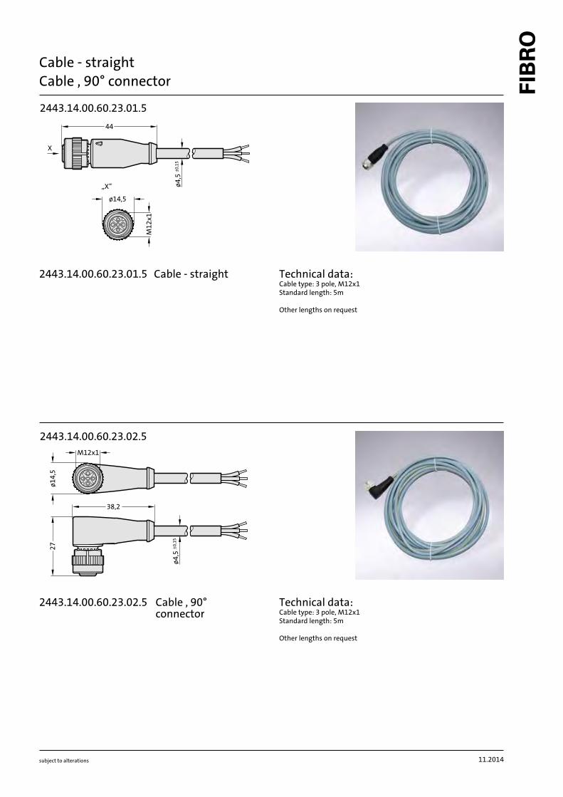
Cable - straightCable , 90° connector
M12x1
ø14,5
ø4,5
±0,15
44
X
„X”
2443.14.00.60.23.01.5
38,2
ø14,5
M12x1
27
ø4,5
±0,15
2443.14.00.60.23.02.5
Technical data:Cable type: 3 pole, M12x1Standard length: 5m
Other lengths on request
Technical data:Cable type: 3 pole, M12x1Standard length: 5m
Other lengths on request
11.2014
2443.14.00.60.23.01 .5
2443.14.00.60.23.02 .5
Cable - straight
Cable , 90° connector

subject to alterations
Loading Diagram for Ball Bearing Guides
f s833
27
20 40 60 80 100 120 1400
110
410
210
310
[h]
21
15
12
96
3
30
24
18
2. H
nf
= v
.[m
m. m
in.
]-1
[H . min. ]-1nf = strokes per minute
C = dynamic load index [N]
f = impact factor 1
F = radial load acting on guide [N]
2 . H nf. [mm . min. ]-1v =
s
L =h333
2 . H nf.. C
. F3
H = stroking length [mm]
Loading [% of C]
Bea
rin
g Li
fe L
h
Bearing Life versus Loading:
Values shown are based on the Impact Factor of f
s
= 1
which is applicable to normal conditions in respect of die set and press,
with a maximum bearing temperature of 100 °C.
D286
8 40 450
10 40 1630
10 56 2210
11 40 1660
11 56 2250
12 40 1680
12 56 2280
15 45 3300
15 56 4050
15 63 4550
15 71 4950
16 24 1910
16 28 2230
16 45 3350
16 56 4100
16 63 4600
16 71 5000
19 31 3050
19 45 4050
19 56 4950
19 71 6100
19 80 6600
19 95 7600
20 24 2320
20 28 2700
20 31 3100
20 45 4100
20 56 5000
20 71 6100
20 80 6600
20 95 7600
24 31 3150
24 40 3850
24 45 4200
24 56 5100
24 71 6300
24 80 6800
24 95 7800
24 120 9300
25 31 3200
25 40 3900
25 45 4200
25 56 5200
25 71 6300
25 80 6900
25 95 7900
25 120 9300
30 40 5700
30 45 6400
30 50 7000
30 56 7600
30 71 9300
30 75 9800
30 80 10400
30 95 11900
30 105 12800
30 120 14200
30 140 16000
30 160 17700
32 40 5800
32 45 6400
32 50 7100
32 56 7700
32 71 9400
32 75 9900
32 80 10500
32 95 12000
32 105 12900
32 120 14300
32 140 16100
32 160 17800
38 45 7500
38 50 8200
38 56 8900
38 63 10300
38 80 12100
38 95 13900
38 105 15000
38 120 16700
38 140 18700
38 160 20700
38 180 22600
38 200 24400
38 240 28000
40 45 7500
40 50 8200
40 56 9000
40 63 10300
40 80 12200
40 95 14000
40 105 15100
40 120 16700
40 140 18800
40 160 20800
40 180 22700
40 200 24600
40 240 28000
48 50 9400
48 63 11700
48 80 13800
48 95 15900
48 105 17100
48 120 19000
48 140 21400
48 160 23600
48 180 26000
48 200 28000
48 240 32000
50 50 9400
50 63 11700
50 80 13900
50 95 15900
50 105 17200
50 120 19100
50 140 21400
50 160 23700
50 180 26000
50 200 28000
50 240 32000
60 95 17700
60 105 19200
60 120 21300
60 140 23900
60 160 26500
60 180 29000
60 200 31000
60 240 35500
63 95 17800
63 105 19300
63 120 21300
63 140 24000
63 160 26500
63 180 29000
63 200 31500
63 240 35500
80 120 41000
80 140 46500
80 160 52000
80 180 57000
80 200 62000
80 240 70000
subject to alterations
Safe Loads for FIBRO Ball Bearing Guides
Tables of Dynamic Load Indexes
Definition:
The dynamic load index C constitutes a constant loading that will allow the respective sizes of ball bearing guides to reach + 105 m without any discernible
bearing damage. The load index is shown in N and results from tests executed with batches of sufficient size, subjected to linear travel oscillations and
radially imposed loads of constant magnitude and unchanging direction.
Pillar [ d
1
Cage length l
1
Dynamic Load Index C
for whole cage (N)
Pillar [ d
1
Cage length l
1
Dynamic Load Index C
for whole cage (N)

8 40 450
10 40 1630
10 56 2210
11 40 1660
11 56 2250
12 40 1680
12 56 2280
15 45 3300
15 56 4050
15 63 4550
15 71 4950
16 24 1910
16 28 2230
16 45 3350
16 56 4100
16 63 4600
16 71 5000
19 31 3050
19 45 4050
19 56 4950
19 71 6100
19 80 6600
19 95 7600
20 24 2320
20 28 2700
20 31 3100
20 45 4100
20 56 5000
20 71 6100
20 80 6600
20 95 7600
24 31 3150
24 40 3850
24 45 4200
24 56 5100
24 71 6300
24 80 6800
24 95 7800
24 120 9300
25 31 3200
25 40 3900
25 45 4200
25 56 5200
25 71 6300
25 80 6900
25 95 7900
25 120 9300
30 40 5700
30 45 6400
30 50 7000
30 56 7600
30 71 9300
30 75 9800
30 80 10400
30 95 11900
30 105 12800
30 120 14200
30 140 16000
30 160 17700
32 40 5800
32 45 6400
32 50 7100
32 56 7700
32 71 9400
32 75 9900
32 80 10500
32 95 12000
32 105 12900
32 120 14300
32 140 16100
32 160 17800
38 45 7500
38 50 8200
38 56 8900
38 63 10300
38 80 12100
38 95 13900
38 105 15000
38 120 16700
38 140 18700
38 160 20700
38 180 22600
38 200 24400
38 240 28000
40 45 7500
40 50 8200
40 56 9000
40 63 10300
40 80 12200
40 95 14000
40 105 15100
40 120 16700
40 140 18800
40 160 20800
40 180 22700
40 200 24600
40 240 28000
48 50 9400
48 63 11700
48 80 13800
48 95 15900
48 105 17100
48 120 19000
48 140 21400
48 160 23600
48 180 26000
48 200 28000
48 240 32000
50 50 9400
50 63 11700
50 80 13900
50 95 15900
50 105 17200
50 120 19100
50 140 21400
50 160 23700
50 180 26000
50 200 28000
50 240 32000
60 95 17700
60 105 19200
60 120 21300
60 140 23900
60 160 26500
60 180 29000
60 200 31000
60 240 35500
63 95 17800
63 105 19300
63 120 21300
63 140 24000
63 160 26500
63 180 29000
63 200 31500
63 240 35500
80 120 41000
80 140 46500
80 160 52000
80 180 57000
80 200 62000
80 240 70000
subject to alterations
Safe Loads for FIBRO Ball Bearing Guides
Tables of Dynamic Load Indexes
Definition:
The dynamic load index C constitutes a constant loading that will allow the respective sizes of ball bearing guides to reach + 105 m without any discernible
bearing damage. The load index is shown in N and results from tests executed with batches of sufficient size, subjected to linear travel oscillations and
radially imposed loads of constant magnitude and unchanging direction.
Pillar [ d1 Cage length l1Dynamic Load Index C
for whole cage (N)Pillar [ d1 Cage length l1
Dynamic Load Index C
for whole cage (N)
05.2016
1d
R10
Z
min.
2l
H5js42d
1d
5d
min.
5t
R10
Z
+1
1d
H5js43d
R10
Z
min
.2l
H5j62d
1d
8d
min
.5t
R10
Z
+1
202.17. / 202.19. / 202.22. / 202.23. / 202.24. /
202.29.
3-80
–0,025
–0,035
–0,015
–0,025
2021.46. / 2021.44.
d
5
+1
l
2
t
5
15/16 15/16
+0,008
24 20,5 6,5
19/20 19/20
+0,009
27 23,5 6,5
24/25 24/25
+0,009
34 30,5 6,5
30/32 30/32
+0,011
42 37,5 6,5
38/40 38/40
+0,011
52 37,5 6,5
48/50 48/50
+0,013
62 47,5 6,5
60/63 60/63
+0,013
72 47,5 6,5
80 80
+0,013
95 60,5 12,5
2021.39.
d
1
d
3
H5
19/20 32
+0,011
24/25 40
+0,011
30/32 48
+0,011
38/40 58
+0,013
48/50 70
+0,013
60/63 85
+0,015
2021.29.
d
8
+1
l
2
t
5
15/16 15/16
+0,008
24 20,5 6,5
19/20 19/20
+0,009
27 23,5 6,5
24/25 24/25
+0,009
34 30,5 6,5
30/32 30/32
+0,011
42 37,5 6,5
38/40 38/40
+0,011
52 37,5 6,5
48/50 48/50
+0,013
62 47,5 6,5
60/63 60/63
+0,013
72 47,5 6,5
80 80
+0,013
95 60,5 12,5
subject to alterations
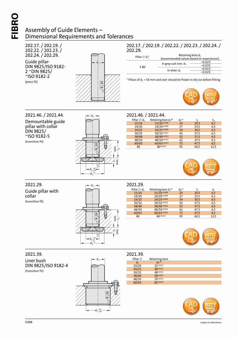
Assembly of Guide Elements –
Dimensional Requirements and Tolerances
202.17. / 202.19. /
202.22. / 202.23. /
202.24. / 202.29.
Guide pillar-
DIN 9825/ISO 9182-
2 ~DIN 9825/
~ISO 9182-2
(press fit)
2021.46. / 2021.44.
Demountable guide
pillar with collar
DIN 9825/
~ISO 9182-5
(transition fit)
2021.39.
Liner bush
DIN 9825/ISO 9182-4
(transition fit)
2021.29.
Guide pillar with
collar
(transition fit)
Pillar ∅ d1
*
Retaining bore d
1
(recommended values based on experiences)
in grey cast iron: d
1
in steel: d
1
* Pillars of d
1
= 50 mm and over should be frozen in dry ice before fitting
Pillar ∅ d1
Retaining bore d
2
H5
Pillar ∅ Retaining bore
Pillar ∅ d1
Retaining bore d
2
H5
D288
1d
H5
m53d
R10
Z
d1
3c
1d
3d H5
js4
R10
Z
10
ZR
1d
H5js43d
3
d
10
Z
R
1
d
210.39.
16 28
+0,009
20 32
+0,011
25 40
+0,011
32 50
+0,011
40 63
+0,013
50 80
+0,013
63 90
+0,015
202.60.
19 25
+0,009
33
25 30
+0,009
33
32 36
+0,011
38
40 46
+0,011
38
2051.32.
8 13,7
+0,008
11/12 22
+0,009
15/16 28
+0,009
19/20 32
+0,011
24/25 40
+0,011
30/32 48
+0,011
38/40 58
+0,013
48/50 70
+0,013
60/63 85
+0,015
80 95,7
+0,015
206.54. 2061.44. / 2061.47
3 7
+0,009
8 18
+0,008
4 8
+0,009
10 22
+0,009
5 10
+0,009
11/12 22
+0,009
6 11
+0,011
15/16 28
+0,009
8 14
+0,011
19/20 32
+0,011
24/25 40
+0,011
30/32 48
+0,011
38/40 58
+0,013
48/50 70
+0,013
60/63 85
+0,015
80 105
+0,015
subject to alterations
Assembly of Guide Elements –
Dimensional Requirements and Tolerances
210.39.
Liner bushes,
similar AFNOR
(transition fit)
Pillar ∅ d
1
Retaining bore
d
3
H
5
202.60.
Demountable guide
pillars with centre
collar
(transition fit)
Pillar ∅ d1
Retaining bore
d
3
H5
Plattendicke
c
3
–1
2051.32.
Sintered ferrite guide
bushes
DIN 9831 /
ISO 9448-2
slip-fit bonding*
Pillar ∅ d
1
Retaining bore
d
3
H
5
206.54.
2061.44./2061.47.
Ball bearing guide
bushes
DIN 9831 /
ISO 9448-3
slip-fit bonding*
Pillar ∅ d
1
Retaining bore
d
3
H
6
Pillar ∅ d
1
Retaining bore
d
3
H
5
*Slip-Fit Bonding:
The glue-line gap must not be smaller than 0,005 mm, or the adhesive will
be wiped off the contact surfaces upon fitment.
This would result in an unreliable bond.
The available component tolerances do not always result in the minimum
glue-line gap.
This fact has to be born in mind when machining receiving bores,
or alternatively corrections can be made on the assembly bench.
1d
R10
Z
min.
2l
H5js42d
1d
5d
min.
5t
R10
Z
+1
1d
H5js43d
R10
Z
min
.2l
H5j62d
1d
8d
min
.5t
R10
Z
+1
202.17. / 202.19. / 202.22. / 202.23. / 202.24. /
202.29.
3-80
–0,025
–0,035
–0,015
–0,025
2021.46. / 2021.44.
d
5
+1
l
2
t
5
15/16 15/16
+0,008
24 20,5 6,5
19/20 19/20
+0,009
27 23,5 6,5
24/25 24/25
+0,009
34 30,5 6,5
30/32 30/32
+0,011
42 37,5 6,5
38/40 38/40
+0,011
52 37,5 6,5
48/50 48/50
+0,013
62 47,5 6,5
60/63 60/63
+0,013
72 47,5 6,5
80 80
+0,013
95 60,5 12,5
2021.39.
d
1
d
3
H5
19/20 32
+0,011
24/25 40
+0,011
30/32 48
+0,011
38/40 58
+0,013
48/50 70
+0,013
60/63 85
+0,015
2021.29.
d
8
+1
l
2
t
5
15/16 15/16
+0,008
24 20,5 6,5
19/20 19/20
+0,009
27 23,5 6,5
24/25 24/25
+0,009
34 30,5 6,5
30/32 30/32
+0,011
42 37,5 6,5
38/40 38/40
+0,011
52 37,5 6,5
48/50 48/50
+0,013
62 47,5 6,5
60/63 60/63
+0,013
72 47,5 6,5
80 80
+0,013
95 60,5 12,5
subject to alterations
Assembly of Guide Elements –
Dimensional Requirements and Tolerances
202.17. / 202.19. /
202.22. / 202.23. /
202.24. / 202.29.
Guide pillar-
DIN 9825/ISO 9182-
2 ~DIN 9825/
~ISO 9182-2
(press fit)
2021.46. / 2021.44.
Demountable guide
pillar with collar
DIN 9825/
~ISO 9182-5
(transition fit)
2021.39.
Liner bush
DIN 9825/ISO 9182-4
(transition fit)
2021.29.
Guide pillar with
collar
(transition fit)
Pillar ∅ d1
*
Retaining bore d
1
(recommended values based on experiences)
in grey cast iron: d
1
in steel: d
1
* Pillars of d
1
= 50 mm and over should be frozen in dry ice before fitting
Pillar ∅ d1
Retaining bore d
2
H5
Pillar ∅ Retaining bore
Pillar ∅ d1
Retaining bore d
2
H5
1d
H5
m53d
R10
Z
d1
3c
1d
3d H5
js4R10
Z
10
ZR
1d
H5js43d
3
d
10
Z
R
1
d
210.39.
16 28
+0,009
20 32
+0,011
25 40
+0,011
32 50
+0,011
40 63
+0,013
50 80
+0,013
63 90
+0,015
202.60.
19 25
+0,009
33
25 30
+0,009
33
32 36
+0,011
38
40 46
+0,011
38
2051.32.
8 13,7
+0,008
11/12 22
+0,009
15/16 28
+0,009
19/20 32
+0,011
24/25 40
+0,011
30/32 48
+0,011
38/40 58
+0,013
48/50 70
+0,013
60/63 85
+0,015
80 95,7
+0,015
206.54. 2061.44. / 2061.47
3 7
+0,009
8 18
+0,008
4 8
+0,009
10 22
+0,009
5 10
+0,009
11/12 22
+0,009
6 11
+0,011
15/16 28
+0,009
8 14
+0,011
19/20 32
+0,011
24/25 40
+0,011
30/32 48
+0,011
38/40 58
+0,013
48/50 70
+0,013
60/63 85
+0,015
80 105
+0,015
subject to alterations
Assembly of Guide Elements –
Dimensional Requirements and Tolerances
210.39.
Liner bushes,
similar AFNOR
(transition fit)
Pillar ∅ d
1
Retaining bore
d
3
H
5
202.60.
Demountable guide
pillars with centre
collar
(transition fit)
Pillar ∅ d1
Retaining bore
d
3
H5
Plattendicke
c
3
–1
2051.32.
Sintered ferrite guide
bushes
DIN 9831 /
ISO 9448-2
slip-fit bonding*
Pillar ∅ d
1
Retaining bore
d
3
H
5
206.54.
2061.44./2061.47.
Ball bearing guide
bushes
DIN 9831 /
ISO 9448-3
slip-fit bonding*
Pillar ∅ d
1
Retaining bore
d
3
H
6
Pillar ∅ d
1
Retaining bore
d
3
H
5
*Slip-Fit Bonding:
The glue-line gap must not be smaller than 0,005 mm, or the adhesive will
be wiped off the contact surfaces upon fitment.
This would result in an unreliable bond.
The available component tolerances do not always result in the minimum
glue-line gap.
This fact has to be born in mind when machining receiving bores,
or alternatively corrections can be made on the assembly bench.
D289

1d
H5js43d
10
ZR
js4
1d
H5
3d
10
ZR
3 m5
H6
d
10
Z
R
1
d
1d
H6j63d
10
ZR
2081.3x. / 2081.4x. / 2081.8x.
19/20
32
+
0,011
24/25 40
+0,011
30/32 48
+0,011
38/40 58
+0,013
48/50 70
+0,013
60/63 85
+0,015
80 105
+0,015
2091.3x. / 2091.4x.
12 26
+0,009
15/16 28
+0,009
19/20 32
+0,011
24/25 40
+0,011
30/32 48
+0,011
38/40 58
+0,013
48/50 70
+0,013
60/63 85
+0,015
80 105
+0,015
206.49.
16 28
+0,013
20 32
+0,016
25 40
+0,016
32 50
+0,016
40 63
+0,019
50 80
+0,019
2081.7x. / 2081.9x.
19/20
32
+
0,016
24/25 40
+0,016
30/32 48
+0,016
38/40 58
+0,019
48/50 70
+0,019
60/63 85
+0,022
80 105
+0,022
subject to alterations
2081.3x. / 2081.4x. /
2081.8x.
Headed guide bushes,
carbonitrided, bron-
ze-coated sintered
types or ball bearing
types
DIN 9831 / ISO 9448-6
DIN 9831 / ISO 9448-7
ISO 9448
(transition fit)
Pillar ∅ d
1
Retaining bore
d
3
H
5
2091.3x. / 2091.4x.
Flanged guide
bushes, carbonitrided
sintered types or ball
bearing types
DIN 9831 / ISO 9448-4
DIN 9831 / ISO 9448-5
(transition fit)
Pillar ∅ d
1
Retaining bore
d
3
H
5
206.49.
Ball bearing guide
bushes similar AFNOR
slip-fit bonding*
Pillar ∅ d
1
Retaining bore
d
3
H
6
2081.7x. / 2081.9x.
Headed guide bushes,
bronze, with solid lu-
bricant rings, bronze
plated
(transition fit)
Pillar ∅ d
1
Retaining bore
d
3
H
6
*Slip-Fit Bonding:
The glue-line gap must not be smaller than 0,005 mm, or the adhesive will
be wiped off the contact surfaces upon fitment.
This would result in an unreliable bond.
The available component tolerances do not always result in the minimum
glue-line gap.
This fact has to be born in mind when machining receiving bores,
or alternatively corrections can be made on the assembly bench.
Assembly of Guide Elements –
Dimensional Requirements and Tolerances
D290
1d
3d
10
ZR
j6
H6
10
ZR
M6h51d
H7
r61d
H6r61d
2091.7x.
19/20 32
+0,016
24/25 40
+0,016
30/32 48
+0,016
38/40 58
+0,019
48/50 70
+0,019
60/63 85
+0,022
80 105
+0,022
2022.25.
25
-0,004
-0,017
32
-0,004
-0,020
40
50
63 -0,005
-0,02480
100
-0,006
-0,028
2022.12. / 2022.15. / 2022.16. / 2022.17. /
2022.19. / 2022.29.
25
+0,021
0
32
+0,025
0
40
50
63 +0,030
080
100
+0,035
0
125 +0,040
0160
2022.13.
40 +0,016
050
63 +0,019
080
subject to alterations
2091.7x.
Guide bush with
solid lubrication
rings DIN 9831 /
ISO 9448-4
(transition fit)
Pillar ∅ d
1
Retaining bore
d
3
H
6
2022.25.
Guide pillar AFNOR
(transition fit)
Pillar ∅ d1
Retaining bore d
1
M6
2022.12. / 2022.15. /
2022.16. / 2022.17. /
2022.19. / 2022.29.
Guide pillar
DIN 9833/ISO 9182-3
Mercedes-Benz /
VDI / VW / WDX
(press fit)
Pillar ∅ d
1
Retaining bore
d
1
H
7
Pillars of d
1
= 50 mm and over should be frozen in dry ice before fitting
2022.13.
Guide pillar VW
(press fit)
Pillar ∅ d
1
Bohrung
d
1
H
6
Pillars of d
1
= 50 mm and over should be frozen in dry ice before fitting
Assembly of Guide Elements –
Dimensional Requirements and Tolerances

1d
H5js43d
10
ZR
js4
1d
H5
3d
10
ZR
3 m5
H6
d
10
Z
R
1
d
1d
H6j63d
10
ZR
2081.3x. / 2081.4x. / 2081.8x.
19/20
32
+
0,011
24/25 40
+0,011
30/32 48
+0,011
38/40 58
+0,013
48/50 70
+0,013
60/63 85
+0,015
80 105
+0,015
2091.3x. / 2091.4x.
12 26
+0,009
15/16 28
+0,009
19/20 32
+0,011
24/25 40
+0,011
30/32 48
+0,011
38/40 58
+0,013
48/50 70
+0,013
60/63 85
+0,015
80 105
+0,015
206.49.
16 28
+0,013
20 32
+0,016
25 40
+0,016
32 50
+0,016
40 63
+0,019
50 80
+0,019
2081.7x. / 2081.9x.
19/20
32
+
0,016
24/25 40
+0,016
30/32 48
+0,016
38/40 58
+0,019
48/50 70
+0,019
60/63 85
+0,022
80 105
+0,022
subject to alterations
2081.3x. / 2081.4x. /
2081.8x.
Headed guide bushes,
carbonitrided, bron-
ze-coated sintered
types or ball bearing
types
DIN 9831 / ISO 9448-6
DIN 9831 / ISO 9448-7
ISO 9448
(transition fit)
Pillar ∅ d
1
Retaining bore
d
3
H
5
2091.3x. / 2091.4x.
Flanged guide
bushes, carbonitrided
sintered types or ball
bearing types
DIN 9831 / ISO 9448-4
DIN 9831 / ISO 9448-5
(transition fit)
Pillar ∅ d
1
Retaining bore
d
3
H
5
206.49.
Ball bearing guide
bushes similar AFNOR
slip-fit bonding*
Pillar ∅ d
1
Retaining bore
d
3
H
6
2081.7x. / 2081.9x.
Headed guide bushes,
bronze, with solid lu-
bricant rings, bronze
plated
(transition fit)
Pillar ∅ d
1
Retaining bore
d
3
H
6
*Slip-Fit Bonding:
The glue-line gap must not be smaller than 0,005 mm, or the adhesive will
be wiped off the contact surfaces upon fitment.
This would result in an unreliable bond.
The available component tolerances do not always result in the minimum
glue-line gap.
This fact has to be born in mind when machining receiving bores,
or alternatively corrections can be made on the assembly bench.
Assembly of Guide Elements –
Dimensional Requirements and Tolerances
1d
3d
10
ZR
j6
H6
10
ZR
M6h51d
H7
r61d
H6r61d
2091.7x.
19/20 32
+0,016
24/25 40
+0,016
30/32 48
+0,016
38/40 58
+0,019
48/50 70
+0,019
60/63 85
+0,022
80 105
+0,022
2022.25.
25
-0,004
-0,017
32
-0,004
-0,020
40
50
63 -0,005
-0,02480
100
-0,006
-0,028
2022.12. / 2022.15. / 2022.16. / 2022.17. /
2022.19. / 2022.29.
25
+0,021
0
32
+0,025
0
40
50
63 +0,030
080
100
+0,035
0
125 +0,040
0160
2022.13.
40 +0,016
050
63 +0,019
080
subject to alterations
2091.7x.
Guide bush with
solid lubrication
rings DIN 9831 /
ISO 9448-4
(transition fit)
Pillar ∅ d
1
Retaining bore
d
3
H
6
2022.25.
Guide pillar AFNOR
(transition fit)
Pillar ∅ d1
Retaining bore d
1
M6
2022.12. / 2022.15. /
2022.16. / 2022.17. /
2022.19. / 2022.29.
Guide pillar
DIN 9833/ISO 9182-3
Mercedes-Benz /
VDI / VW / WDX
(press fit)
Pillar ∅ d
1
Retaining bore
d
1
H
7
Pillars of d
1
= 50 mm and over should be frozen in dry ice before fitting
2022.13.
Guide pillar VW
(press fit)
Pillar ∅ d
1
Bohrung
d
1
H
6
Pillars of d
1
= 50 mm and over should be frozen in dry ice before fitting
Assembly of Guide Elements –
Dimensional Requirements and Tolerances
D291

1d
m62d
1
d
H7
r62
d
1
d
G7
k62
d
10 14 +0,018
012 18
13 19
+0,021
0
14 20
15 21
16 22
20 30
25 35
+0,025
0
30 40
31,5 40
35 45
40 50
45 55
+0,030
0
50 60
55 65
60 75
63 75
70 85
+0,035
0
75 90
80 100
90 110
100 120
120 140
+0,040
0
2052.70.
1)
/ 2086.70. / 2085.72.
8 12
+0,024
+0,006
+0,018
0
10 14/15
12 18
13 19
+0,028
+0,007
+0,021
0
14 20
15 21
16 22
18/19 24/25
20 26/28/30
25 32/33/35
+0,034
+0,009
+0,025
0
28 38
30 38/40/42
31,5 40
32 42
35 44/45
38 48
40 50
40 55
+0,040
+0,010
+0,030
0
45 55/56/60
50 60/62/65
55 70
60 74/75
63 75
65 80
70 85/90
+0,047
+0,012
+0,035
0
75 90/95
80 96/100
85 100
90 110
100 120
110 130
+0,054
+0,014
+0,040
0
120 140
125 145
130 150
140 160
150 170
160 180
2085.70.
12 16
+0,024
+0,006
16 20
+0,028
+0,007
20 26
24 30
2085.71.
subject to alterations
Pillar ∅ d
1
Retaining
bore d
2
limits d
2
H7
Pillar ∅ d
1
Retaining
bore d
2
limits d
2
H7
Pillar ∅ d1
Retaining bore
d
2
bonding limitsd
2
G7
Transition fit limits
d
2
H7
2052.70.
1)
/ 2086.70. /
2085.72.
Guide Bushes/
Guide Bushes with
collar, Bronze with
non-liquid lubricant
slip-fit bonding*:
Retaining bore d
2
= G7
transition fit:
Retaining bore d
2
= H7
1)
if required secure with set screw
2085.71.
Guide Bushes with
collar, Bronze with
non-liquid lubricant
(press fit)
Pillar ∅ d
1
Retaining bore d
2
G7
limits d
2
G7
2085.70.
Guide Bushes with
collar, Bronze with
non-liquid lubricant
(transition fit)
*Slip-Fit Bonding:
The glue-line gap must not be smaller than 0,005 mm, or the adhesive will
be wiped off the contact surfaces upon fitment.
This would result in an unreliable bond.
The available component tolerances do not always result in the minimum
glue-line gap.
This fact has to be born in mind when machining receiving bores,
or alternatively corrections can be made on the assembly bench.
Assembly of Guide Elements –
Dimensional Requirements and Tolerances
D292
1
d
H7
g62
d
1d
H6
m62d
1
d
H7
h62
d
2102.70. / 2102.71.
25 35
+0,016
0
32 44
40 52
+0,019
0
50 63
63 80
80 100
+0,022
0
100 125
+0,025
0
2082.70.
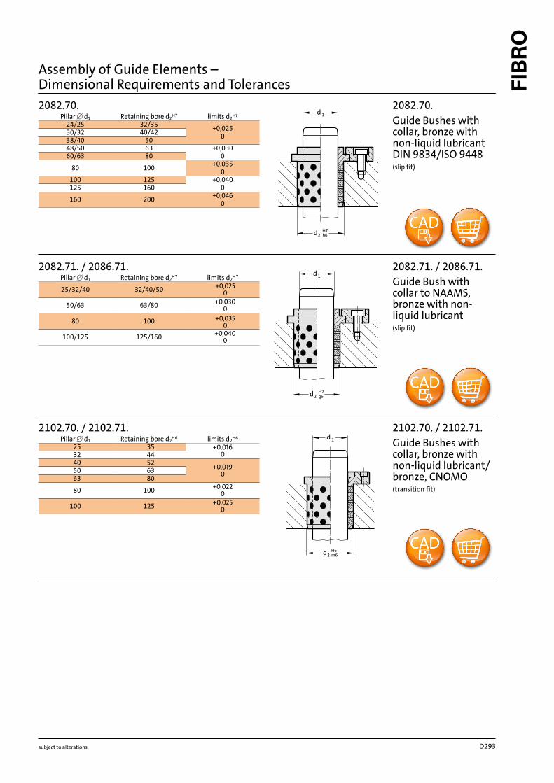
24/25 32/35
+0,025
0
30/32 40/42
38/40 50
48/50 63 +0,030
060/63 80
80 100
+0,035
0
100 125 +0,040
0125 160
160 200
+0,046
0
2082.71. / 2086.71.
25/32/40 32/40/50
+0,025
0
50/63 63/80
+0,030
0
80 100
+0,035
0
100/125 125/160
+0,040
0
subject to alterations
2082.71. / 2086.71.
Guide Bush with
collar to NAAMS,
bronze with non-
liquid lubricant
(slip fit)
2102.70. / 2102.71.
Guide Bushes with
collar, bronze with
non-liquid lubricant/
bronze, CNOMO
(transition fit)
Pillar [ d
1
Retaining bore d
2
H6
limits d
2
H6
2082.70.
Guide Bushes with
collar, bronze with
non-liquid lubricant
DIN 9834/ISO 9448
(slip fit)
Pillar [ d
1
Retaining bore d
2
H7
limits d
2
H7
Pillar [ d
1
Retaining bore d
2
H7
limits d
2
H7
Assembly of Guide Elements –
Dimensional Requirements and Tolerances
1d
m62d
1
d
H7
r62
d
1
d
G7
k62
d
10 14 +0,018
012 18
13 19
+0,021
0
14 20
15 21
16 22
20 30
25 35
+0,025
0
30 40
31,5 40
35 45
40 50
45 55
+0,030
0
50 60
55 65
60 75
63 75
70 85
+0,035
0
75 90
80 100
90 110
100 120
120 140
+0,040
0
2052.70.
1)
/ 2086.70. / 2085.72.
8 12
+0,024
+0,006
+0,018
0
10 14/15
12 18
13 19
+0,028
+0,007
+0,021
0
14 20
15 21
16 22
18/19 24/25
20 26/28/30
25 32/33/35
+0,034
+0,009
+0,025
0
28 38
30 38/40/42
31,5 40
32 42
35 44/45
38 48
40 50
40 55
+0,040
+0,010
+0,030
0
45 55/56/60
50 60/62/65
55 70
60 74/75
63 75
65 80
70 85/90
+0,047
+0,012
+0,035
0
75 90/95
80 96/100
85 100
90 110
100 120
110 130
+0,054
+0,014
+0,040
0
120 140
125 145
130 150
140 160
150 170
160 180
2085.70.
12 16
+0,024
+0,006
16 20
+0,028
+0,007
20 26
24 30
2085.71.
subject to alterations
Pillar ∅ d
1
Retaining
bore d
2
limits d
2
H7
Pillar ∅ d
1
Retaining
bore d
2
limits d
2
H7
Pillar ∅ d1
Retaining bore
d
2
bonding limitsd
2
G7
Transition fit limits
d
2
H7
2052.70.
1)
/ 2086.70. /
2085.72.
Guide Bushes/
Guide Bushes with
collar, Bronze with
non-liquid lubricant
slip-fit bonding*:
Retaining bore d
2
= G7
transition fit:
Retaining bore d
2
= H7
1)
if required secure with set screw
2085.71.
Guide Bushes with
collar, Bronze with
non-liquid lubricant
(press fit)
Pillar ∅ d
1
Retaining bore d
2
G7
limits d
2
G7
2085.70.
Guide Bushes with
collar, Bronze with
non-liquid lubricant
(transition fit)
*Slip-Fit Bonding:
The glue-line gap must not be smaller than 0,005 mm, or the adhesive will
be wiped off the contact surfaces upon fitment.
This would result in an unreliable bond.
The available component tolerances do not always result in the minimum
glue-line gap.
This fact has to be born in mind when machining receiving bores,
or alternatively corrections can be made on the assembly bench.
Assembly of Guide Elements –
Dimensional Requirements and Tolerances
1
d
H7
g62
d
1d
H6
m62d
1
d
H7
h62
d
2102.70. / 2102.71.
25 35
+0,016
0
32 44
40 52
+0,019
0
50 63
63 80
80 100
+0,022
0
100 125
+0,025
0
2082.70.
24/25 32/35
+0,025
0
30/32 40/42
38/40 50
48/50 63 +0,030
060/63 80
80 100
+0,035
0
100 125 +0,040
0125 160
160 200
+0,046
0
2082.71. / 2086.71.
25/32/40 32/40/50
+0,025
0
50/63 63/80
+0,030
0
80 100
+0,035
0
100/125 125/160
+0,040
0
subject to alterations
2082.71. / 2086.71.
Guide Bush with
collar to NAAMS,
bronze with non-
liquid lubricant
(slip fit)
2102.70. / 2102.71.
Guide Bushes with
collar, bronze with
non-liquid lubricant/
bronze, CNOMO
(transition fit)
Pillar [ d
1
Retaining bore d
2
H6
limits d
2
H6
2082.70.
Guide Bushes with
collar, bronze with
non-liquid lubricant
DIN 9834/ISO 9448
(slip fit)
Pillar [ d
1
Retaining bore d
2
H7
limits d
2
H7
Pillar [ d
1
Retaining bore d
2
H7
limits d
2
H7
Assembly of Guide Elements –
Dimensional Requirements and Tolerances
D293

1
d
H7
e7, f7
2
d
H7
h6, k6
2
d
1
d
e72
d
H7
k62
d
1
d
H7
g62
d
3120.70. / 3120.71.
8 12
+0,018
0
10 14/15
12 18
13 19
+0,021
0
14 20
15 21
16 22
18/19 24/25
20 26/28/30
25 32/33/35
+0,025
0
28 38
30 38/40/42
31,5 40
32 42
35 44/45
38 48
40 50
40 55
+0,030
0
45 55/56/60
50 60/62/65
55 70
60 74/75
63 75
65 80
70 85/90
+0,035
0
75 90/95
80 96/100
85 100
90 110
100 120
110 130
+0,040
0
120 140
125 145
130 150
140 160
150 170
160 180
2087.72.
9/10 14 +0,018
012 18
14/15 20
+0,021
0
16 22
18/20 26
22/24 30
25 32 +0,025
030/32 42
40/42 54
+0,030
0
50 66
60 80
2087.70. / 2087.71. / 2087.73.
9/10 14
+0,018
0
14/15 20
+0,021
0
18/20 26
22/24 30
25 35
+0,025
0
30/32 42
40 50
40/42 54
+0,030
0
50 63
60 80
63 80
subject to alterations
Pillar [ d1
Retaining bore d
2
H7
limits d
2
H7
2087.70. / 2087.71. /
2087.73.
Guide Bushes with
centre collar/ with
collar, bronze with
non-liquid lubricant
e7 = slip fit
f7 = slip fit
h6 = slip fit
k6 = transition fit
2087.72.
Guide Bushes with
collar, bronze with
non-liquid lubricant
e7 = slip fit
k6 = transition fit
Pillar [ d
1
Retaining bore d
2
H7
limits d
2
H7
Pillar [ d
1
Retaining bore d
2
H7
limits d
2
H7
3120.70. / 3120.71.
Guide Bushes, bronze
with non-liquid
lubricant
slip fit
bond in or if required secure with
set screw or flat mushroom head
screw 2192.61.
Assembly of Guide Elements –
Dimensional Requirements and Tolerances
D294


