
Guide To Technical Report Writing 1 v5.1
Faculty of Engineering and the Built Environment
Department of Electronic Engineering
Guide to Technical Report Writing
Introduction
A technician who is unable to communicate effectively with his superiors or colleagues will never
receive due credit for his/her work. Information must be transmitted in a clear and concise manner
in order to enable decisions to be made. The most popular method of technical communication is via
the report.
Points to consider before starting your report
The following should be considered prior to starting your report:
1. Why is the report being written?
2. Have the contents been planned in a manner that can be easily understood by the reader?
3. Who will read the report?
This decides the level of technical information that is to be included.
Suggestions to improve the quality and presentation of your report
1. Choose a short, meaningful title;
2. Include as many tables and diagrams as you think are appropriate. Remember that a single
diagram will often clarify what would otherwise be a very confused paragraph;
3. Use a simple, clear style of writing. Long and involved sentences are a hindrance to easy
understanding and often contain grammatical errors.
Format of the Start of the Report: Title Page and Plagiarism Declaration
The format to be followed for the title page and plagiarism declaration is shown on the next page.
Note that a correctly formatted template in MSWord format is available for download from the
department website under the Industrial Project 4 section.

Guide To Technical Report Writing 2 v5.1
Project Title
By
Your Surname and Initials here
Your Student Number here
Submitted in the Faculty of Engineering: Department of Electronic Engineering
in Partial Fulfillment of the Requirements for the
National Diploma in Electronic Engineering
at the
Durban University of Technology
Insert Month and Year Here
___________________________
Signature of Student
___________________________ ___________________________
Signature of Supervisor Date
16 pt Calibri, bold Centre justification
12 pt, bold
Bachelor of Technology for B.Tech degree

Guide To Technical Report Writing 3 v5.1
PLAGIARISM DECLARATION
1. I know and understand that plagiarism is using another person’s work and pretending it is
one’s own, which is wrong.
2. This report is my own work.
3. I have appropriately referenced the work of other people I have used.
4. I have not allowed, and will not allow, anyone to copy my work with the intention of passing
it off as his/her own work.
___________________________ __________________ _____________________________ Surname and Initials Student Number Signature ___________________________ Date
14 pt, bold
11 pt

Guide To Technical Report Writing 4 v5.1
REPORT LAYOUT
The following sections are typically included in all technical reports. Each section is to start on a new
page:
Acknowledgements (BTECH ONLY)
Optional: You can use this section to express your gratitude to those who assisted you with your
project. Only necessary with large reports and should not be used to increase the size of your
document.
Abstract (BTECH ONLY)
A clear and concise summary of the contents of the report, stating your aim, results obtained and
conclusions reached.
Table of Contents
The contents list must contain the main and sub-paragraph headings and the respective page
numbers. The table of contents is formatted using right tab stops with dot leaders. (see example on
page 7)
List of Figures and/or Tables (OPTIONAL at Undergraduate Level)
List of Constants and Abbreviations (OPTIONAL at Undergraduate Level)
CHAPTER 1 – INTRODUCTION
The objective of this chapter is to introduce the reader to the problem using relevant background
information on the topic, and to point out the purpose and significance of the report. The
specifications and scope of the project are clearly defined.
CHAPTER 2 – DESIGN
The body contains the primary message of the report, described in detail. The subject matter
discussed in the body must be logically developed and presented in a manner that is easy for the
reader to understand. All aspects of your design are to be discussed in this section.
System Block Diagram: Give the system’s block diagram including signals and discuss the function of
each stage (block on the diagram).
Circuit Diagram: If relevant, draw the circuit diagram and clearly indicate all its different stages. The
methodology used to design your circuit must also be discussed in this chapter. For example, if you
were designing a driver circuit to provide sufficient current to operate the car motors, then you must
describe the operation of this circuit and also mention the points taken into consideration during the
selection of the driver transistor/s or integrated circuit. All information on the selected components
can be found in the respective data sheets and application notes. Calculations are to be shown
wherever necessary. Also mention any safety features that you may have incorporated in your

Guide To Technical Report Writing 5 v5.1
design. For example, you may have used an opto-coupler to isolate the micro-controller from the
motor driver circuit.
CHAPTER 3 – CONSTRUCTION
CHAPTER 4 – TESTING
Procedures used to test various stages of the project must be included here.
Software and software design: For micro-controller based projects, the software design method
must be given. For high-level programming, the top-down design should be included.
Certain aspects of the software, such as any calculations used must also be detailed in this chapter.
The complete software listing must be shown in an annexure.
CHAPTER 5 – RESULTS
All results obtained during testing should be documented and compared to expected results.
Remember, a graphical representation of your results is usually more meaningful and therefore
preferable to tabulated results.
Analysis of the results should also be documented.
CHAPTER 6 – CONCLUSION
This chapter discusses the efficiency of the system’s design and the conclusions arrived at, based
upon the performance of the design ascertained during the testing stage. You may also make any
worthwhile recommendations, to improve the performance of your project, in this chapter.
REFERENCES
All references used to design your system must be stated and referred to in the body of the report.
The following format must be adhered to when stating references:
[1] Cebekhulu R, Groenewald S, Naidoo T, Student’s Guide to Project Design. Prentice-Hall, 2000.
[2] Astronomy 161 The Solar System, available at:
http://csep10.phys.utk.edu/astr161/lect/time/coordinates.html [accessed 10 September
2007]
[3] Chambers W R, Dictionary for Science and Technology. Pearson, 2009.
[4] Bose N K, Digital Filters, Theory and Applications, 2nd Edition. Elsevier Science Publishing
Company, New York, 1975.
[5] ANSI/IEEE Standard 488.1, IEEE Standard Digital Interface for Programmable Instrumentation.
Institute of Electrical and Electronic Engineers, New York, 1987.
Note that for website references, the actual website page reference must be used and NOT simply
the generic website address (see [2] above). The date the website is accessed must also be included.

Guide To Technical Report Writing 6 v5.1
ANNEXURES
The following are examples of the type of data that could appear in an annexure:
Complete Circuit Schematic
PCB Layout
Bill of Materials (costing table)
Full Code Listings
Data sheets should be included as an annexure only if certain details on the datasheet need to be
referenced in your text. If details on the datasheet are not needed as a reference in the body of the
report, the datasheet should NOT be included.

Guide To Technical Report Writing 7 v5.1
TABLE OF CONTENTS
PRELIMINARIES
Acknowledgements .................................................................................................................................. ii
Abstract ................................................................................................................................................... iii
Table of Contents .................................................................................................................................... iv
List of Figures ........................................................................................................................................... v
List of Tables ............................................................................................................................................ vi
Constants and Abbreviations ................................................................................................................ viii
CHAPTER 1 (Introduction – this chapter details research done into your project topic)
1.1 Background Information .................................................................................................................... 1
1.3 Project Specifications ......................................................................................................................... 4
CHAPTER 2 (Design – this chapter details the design of the project and problems overcome)
2.1 Project Design .................................................................................................................................... 5
2.1.1 Mechanical ............................................................................................................................ 6
2.1.2 Electronic ............................................................................................................................... 9
2.1.3 Software .............................................................................................................................. 12
CHAPTER 3 (Construction – this chapter details any construction of the project)
3.1 Mechanical ....................................................................................................................................... 15
3.2 Electrical ........................................................................................................................................... 16
CHAPTER 4 (Testing - details the testing procedures that you used to obtain your results)
4.1 Electronic .......................................................................................................................................... 17
4.2 Software ........................................................................................................................................... 18
CHAPTER 5 (Results - results listed graphically and the analysis of those results)
5.1 Analysis of Results ............................................................................................................................ 20
CHAPTER 6 (Conclusion – must be based on the results and analysis that you have obtained)
5.1 Conclusion ........................................................................................................................................ 27
5.2 Recommendations ........................................................................................................................... 28
REFERENCES ......................................................................................................................................... 29
Annexure A: Schematic ......................................................................................................................... 30
Annexure B: PCB Layout ........................................................................................................................ 31
Annexure C: Bill of Materials ................................................................................................................ 32
Annexure D: Code Listing ...................................................................................................................... 33
An example of the Table of Contents layout. Note that headings marked with asterisks may not be included in undergraduate reports.
* *
* * *
Note that page numbers and sub-headings listed are for example only!
Guide To Technical Report Writing 8 v5.1
Report Format
The following format must be adhered to when writing a technical report:
1. Font / Typeface
The body text of the document must be typed in Calibri 11pt font.
2. Paper
Only one side of white, A4, bond paper is to be used.
3. Page Margins
Left margin = 3cm
Right margin = 2cm
Top and bottom margins = 2cm
The left margin must be greater than the right margin to allow for binding along the left of the
page.
4. Justification
Full justification is to be used for the body of the text.
5. Line Spacing and Document Length
1.5 line spacing should be used throughout the document text. An extra line space should
appear between paragraphs. For code listings, a line spacing of 1.15 is used.
6. Pagination
The page number should appear centered at the bottom in the footer of the page. The page
number should appear on its own and should not be followed by a full stop.
7. Italics / Bold / Underlining
Italic/bold should always be used for emphasis. Underlining is not to be used at all in a
technical document.
8. Tense
The report is to be written in the third person, past tense, for example “the instrument was
calibrated” as opposed to “I calibrated the instrument”.
Guide To Technical Report Writing 9 v5.1
9. Punctuation for lists
The following punctuation rules must be applied when using bulleted lists:
1. First point;
2. Second point;
3. Third point.
Tab stops (not spaces) are used to align bulleted and numbered lists.
10. Spelling and Grammar
The authority on spelling is the Oxford English Dictionary. The spell check facility on the word
processor must be used to check the document spelling but remember to use either the South
African or UK dictionary (NOT the USA dictionary). It is a good idea to get someone else, not
necessarily a technical person, to read what you have written and to check for grammatical
errors. Do not make the report sound like a pub chat. Remember that it is a technical
document and should read as such.
11. Abbreviations
Abbreviations should be avoided if possible. If using abbreviations always omit full stops, eg
NSRI, not N.S.R.I.
12. Numbers
The general rule for using numbers is to spell out larger numbers which can be expressed in
two words, eg two million. For other numbers use numerals, eg. 2054 students, 139 pages.
Numerals must be used for dates, street numbers, telephone numbers, decimal values and
percentages. Numerals should also be used if the number has a unit associated with it eg 5 V,
32 MHz. See the booklet titled “Standard Symbols and Notation” for details.
13. Equations
Word processors have an equation editing facility which correctly formats an equation. All
equations must be numbered and this number must be used when referring to the equation in
the body of the text. The following shows an example of an equation number 10 in Chapter 2:
2
3
x
cmxy
[2-10]
A line space must be inserted before and after the equation.
Guide To Technical Report Writing 10 v5.1
14. Quotations
All quotations should be within double quotation marks and the source thereof must be
acknowledged with the reference in square brackets eg “This is a quotation” [12].
15. Units
Always refer to measured quantities in terms of their SI units and accepted derivations
thereof. This applies to all text, tables, graphs and calculations. The omission of physical units
in an engineering report is totally unacceptable.
16. Table of Contents
The layout of the table of contents is set up using tab stops. The last tab stop must be a Right
Tab Stop with a Dot Leader which automatically inserts the dots into the line up to the page
number. Note the type of numbers for each section (Roman numerals or integers). (See
example on page 7)
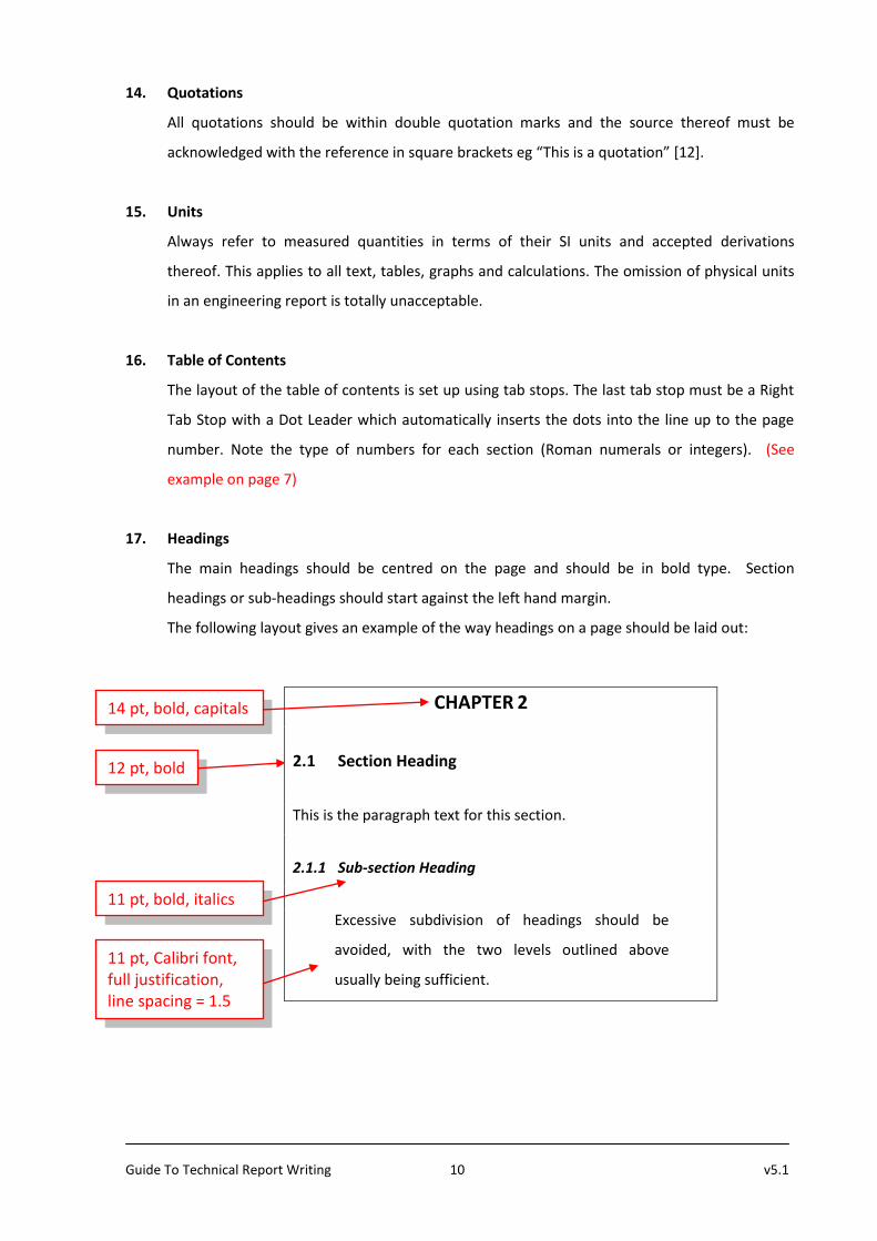
17. Headings
The main headings should be centred on the page and should be in bold type. Section
headings or sub-headings should start against the left hand margin.
The following layout gives an example of the way headings on a page should be laid out:
CHAPTER 2
2.1 Section Heading
This is the paragraph text for this section.
2.1.1 Sub-section Heading
Excessive subdivision of headings should be
avoided, with the two levels outlined above
usually being sufficient.
14 pt, bold, capitals
12 pt, bold
11 pt, bold, italics
11 pt, Calibri font, full justification, line spacing = 1.5

Guide To Technical Report Writing 11 v5.1
18. Tables
All tables used in the report must be numbered and titled and referred to in the text. Do not
include tables in the document that are not referred to.
19. Diagrams / Figures
Diagrams are a very important communication tool in a technical report. The objective of a
report is to convey information to the reader in the clearest, most effective way. Technical
information is often best communicated with the aid of a diagram.
Before including a diagram in your report, consider the information you wish to convey and
whether the proposed diagram conveys this information clearly. Conversely, consider whether
a proposed textual explanation would be more effective if a diagram was used.
Diagrams must always be accompanied by explanatory text that makes clear reference to the
diagram. A diagram must be numbered (eg Figure 3.2 for the second diagram of Chapter 3)
and the diagram must have a title. (See examples on page 12)
Diagrams must be kept simple, clear and fully explained with supporting text. Block diagrams
are particularly useful in the introduction and early chapters of a report. Circuit diagrams, flow
charts and line graphs are other commonly used diagrams in Electronic Engineering reports.
Take Note:
Do not waffle or try to pad the report with unnecessary or irrelevant information.
Technical reports should be concise and to the point.
Do not conclude that results “were as expected” or “not expected”, “that you learnt a
lot”, “that the project was interesting”, “that the equipment broke down”, “that the
results were good, bad, inaccurate, etc.”, unless you have argued these points in the
discussion and you have quoted figures to back up your statement in the conclusion.

Guide To Technical Report Writing 12 v5.1
Examples of Diagrams/Figures
Figure 19.1 is a block diagram of the complete system. This project deals with the design,
construction, and testing of the D/A converter, the amplifier and the speaker. The rest of the block
diagram of Figure 19.1 falls outside the scope of this project.
Figure 19.1: Audio Playback System Block Diagram
The graph of Figure 19.2 shows a four times oversampled audio signal. The difference between two
recorded digital samples is divided by four. This quarter difference is then added to the first sample
three times to generate three additional virtual samples.
Figure 19.2: Four-times Linear Interpolated Oversampling
Audio Signal
Recorded Samples
Interpolated Virtual Samples
Time
Quarter
Amplitude
Difference
FLASH MEMORY
8 M X 16 bit
PROCESSOR
D/A
AMP 8 bits 16 bits
TRIGGER
DEVICE DEVICE DEVICE
CONVERTER
DEVICE


