
Selection Materials
SelectionMaterials8
HSelection M
aterialsSelectionMaterials 9
H
20 25 32 40 50 63 80 100 125 140 150 160 180 200 224 250Model
Generalhydrauliccylinders
Compact designhydraulic cylinders(space-saving type)
Tube flange typehydraulic cylinders
applicable to long strokes
Hydraulic cylinderswith stroke adjusteron retraction side
Series
35Z-135Z-1R
Mounting styleNominalpressure(MPa)
3.5 HA2
HA14
HA50
HA66
HA106
HA106
HA188
HA254
SD, LB, FA, FB, CA, CB
SD, LA, LB, FA, FB, CA, CB, TA, TC
SD, LB, FA, CA
SD, LA, FA, FB, EA, EB, CB, TA, TC
SD, LA, LC, LB, FA, FY, FC, FE, FB, FZ, FD, CA, CB, CS, TA, TC
SD, LA, LC, FY, FC, FE, FZ, FD, CA, CB, CS, TA, TC
SD, LA, EA, EB, FA, FE, FB, CA, CB, TA, TC
SD, LA, FA, FB, CA, CB, TC
SD
SD, LD, FA, FB
SD, ST, LA, LD, FA,FB
SD, LA, FA, FB, CA, CB, TC
LC, LA, FG, FH, CA, TA, TC
3.5
10
10
7
14
16
3.5
10
16
SD, LD, FA, FB
Rated pressure16
SD21
21
SD, LA, LB, FA, FC, FK, FY, TA, TC
SD, LA, FC, FK, FY, TA, TC
7
14
21
14
Standardtype
SwitchSet
Cutting oilproof
Cylinder bore Page
35H-335H-3R
100Z-1100Z-1R
100H-2100H-2R
70H-870H-8R
140H-8140H-8R
160H-1160H-1R
210C-1210C-1R
210H-3
140L-1
35S-135S-1R
70H-8A270H-8RA2
140H-8A2140H-8RA2
HQS2HQS2R
100S-1100S-1R
160S-1160S-1R
210S-1210S-1R
SA, SB, EA, EB, FA,FB, LD16160ST-1
160ST-1R
HA172
HA172
HB2
HB22
HB54
HB86
HB138
HC2
HA288
HA232
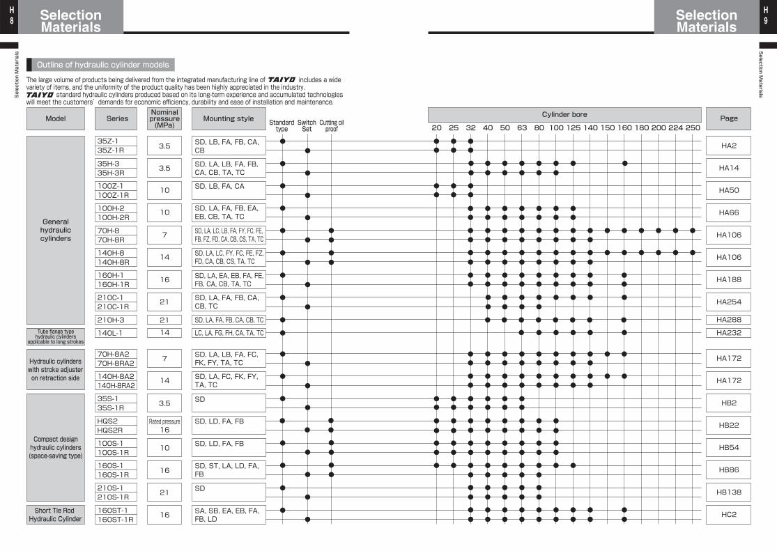
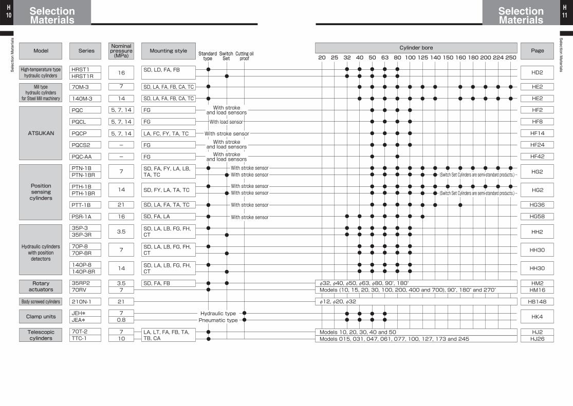
Outline of hydraulic cylinder models
The large volume of products being delivered from the integrated manufacturing line of includes a wide variety of items, and the uniformity of the product quality has been highly appreciated in the industry. standard hydraulic cylinders produced based on its long-term experience and accumulated technologies will meet the customers’demands for economic efficiency, durability and ease of installation and maintenance.
Short Tie Rod Hydraulic Cylinder
Selection Materials
SelectionMaterials10
HSelection M
aterialsSelectionMaterials 11
H
Standardtype
SwitchSet
Cutting oilproof 20 25 32 40 50 63 80 100 125 140 150 160 180 200 224 250
Model
Mill typehydraulic cylinders
for Steel Mill machinery
ATSUKAN
Hydraulic cylinderswith positiondetectors
Rotaryactuators
Body screwed cylinders
Clamp units
Telescopiccylinders
Series
PTN-1BPTN-1BR
Mounting style
7
HG2
SD, LA, FA, FB, CA, TC
SD, LA, FA, FB, CA, TC
FG
FG
LA, FC, FY, TA, TC
SD, LA, LB, FG, FH, CT
SD, LA, LB, FG, FH, CT
SD, LA, LB, FG, FH, CT
SD, FA, FB
14
5, 7, 14
5, 7, 14
5, 7, 14
FG-
FG-
70.8
3.5
14Positionsensingcylinders
SD, FA, FY, LA, LB, TA, TC
SD, FY, LA, TA, TC
21 SD, LA, FA, TA, TC
7
16
7
14
3.57
21
710
Cylinder bore Page
f32, f40, f50, f63, f80, 90 , 180゜Models (10, 15, 20, 30, 100, 200, 400 and 700), 90°, 180° and 270°
Models 10, 20, 30, 40 and 50Models 015, 031, 047, 061, 077, 100, 127, 173 and 245
f12, f20, f32
With strokeand load sensors
With load sensor
With stroke sensorWith stroke
and load sensorsWith stroke
and load sensors
With stroke sensorWith stroke sensor
Hydraulic typePneumatic type
LA, LT, FA, FB, TA,TB, CA
(Switch Set Cylinders are semi-standard products.)
(Switch Set Cylinders are semi-standard products.)
SD, FA, LA
70M-3
140M-3
PQC
PQCL
PQCP
PQCS2
PQC-AA
PTT-1B
PSR-1A
PTH-1BPTH-1BR
35P-335P-3R
70P-870P-8R
140P-8140P-8R
35RP270RV
210N-1
JEH*JEA*
70T-2TTC-1
With stroke sensorWith stroke sensor
With stroke sensor
With stroke sensor
HE2
HE2
HF2
HF8
HF14
HF24
HF42
HD2
HG2
HG36
HG58
HH2
HH30
HH30
HM2HM16
HB148
HK4
HJ2HJ26
Nominalpressure(MPa)
High-temperature typehydraulic cylinders
SD, LD, FA, FB16HRST1HRST1R
Selection Materials
SelectionMaterials12
HSelection M
aterialsSelectionMaterials 13
H
Description
Set pressure of hydraulic circuit
Weight of object to be moved and angle of gravity
Position for installation, how cylinders work, and existence of side load
Cylinder stroke required by equipment and cylinder stroke margin
Max. cylinder operating speed and cylinder operating speed when rushing to cushion
Number of times of operation per hour
Type of hydraulic fluid to be used
Temperature, dust, vibration, splash of cutting oil, etc.
Item
1. Set pressure (MPa)
2. Load weight (kg)
3. Load operating state
4. Required cylinder stroke (mm)
5. Operating speed (mm/s)
6. Frequency of operation (times/hr)
7. Hydraulic fluid
8. Ambient conditions See note.
Note: If the cylinder is used and stored in an environment where it is splashed with water, seawater or the humidity is high, contact us about rust and corrosion prevention.
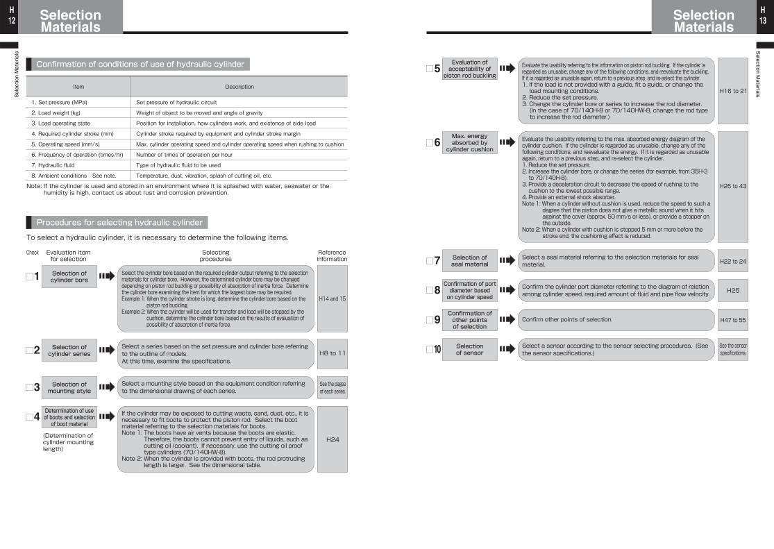
To select a hydraulic cylinder, it is necessary to determine the following items.
1
H8 to 112
Selection ofcylinder bore
H14 and 15
Check Referenceinformation
Selectingprocedures
Evaluation itemfor selection
Confirmation of conditions of use of hydraulic cylinder
Procedures for selecting hydraulic cylinder
3
H24
4
(Determination ofcylinder mountinglength)
See the pagesof each series.
Selection ofcylinder series
Selection ofmounting style
Determination of useof boots and selectionof boot material
Select the cylinder bore based on the required cylinder output referring to the selection materials for cylinder bore. However, the determined cylinder bore may be changed depending on piston rod buckling or possibility of absorption of inertia force. Determine the cylinder bore examining the item for which the largest bore may be required.Example 1: When the cylinder stroke is long, determine the cylinder bore based on the
piston rod buckling.Example 2: When the cylinder will be used for transfer and load will be stopped by the
cushion, determine the cylinder bore based on the results of evaluation of possibility of absorption of inertia force.
If the cylinder may be exposed to cutting waste, sand, dust, etc., it is necessary to fit boots to protect the piston rod. Select the boot material referring to the selection materials for boots.Note 1: The boots have air vents because the boots are elastic.
Therefore, the boots cannot prevent entry of liquids, such as cutting oil (coolant). If necessary, use the cutting oil proof type cylinders (70/140HW-8).
Note 2: When the cylinder is provided with boots, the rod protruding length is larger. See the dimensional table.
Select a series based on the set pressure and cylinder bore referring to the outline of models.At this time, examine the specifications.
Select a mounting style based on the equipment condition referring to the dimensional drawing of each series.
5
6
7
8
9
10
H16 to 21
H26 to 43
H22 to 24
H47 to 55
See the sensorspecifications.
H25
Evaluation ofacceptability ofpiston rod buckling
Max. energyabsorbed by
cylinder cushion
Selection ofseal material
Confirmation of portdiameter basedon cylinder speed
Confirmation ofother pointsof selection
Selectionof sensor
Evaluate the usability referring to the information on piston rod buckling. If the cylinder is regarded as unusable, change any of the following conditions, and reevaluate the buckling. If it is regarded as unusable again, return to a previous step, and re-select the cylinder.1. If the load is not provided with a guide, fit a guide, or change the load mounting conditions.
2. Reduce the set pressure.3. Change the cylinder bore or series to increase the rod diameter.(In the case of 70/140H-8 or 70/140HW-8, change the rod type to increase the rod diameter.)
Evaluate the usability referring to the max. absorbed energy diagram of the cylinder cushion. If the cylinder is regarded as unusable, change any of the following conditions, and reevaluate the energy. If it is regarded as unusable again, return to a previous step, and re-select the cylinder.1. Reduce the set pressure.2. Increase the cylinder bore, or change the series (for example, from 35H-3 to 70/140H-8).
3. Provide a deceleration circuit to decrease the speed of rushing to the cushion to the lowest possible range.
4. Provide an external shock absorber.Note 1: When a cylinder without cushion is used, reduce the speed to such a
degree that the piston does not give a metallic sound when it hits against the cover (approx. 50 mm/s or less), or provide a stopper on the outside.
Note 2: When a cylinder with cushion is stopped 5 mm or more before the stroke end, the cushioning effect is reduced.
Select a seal material referring to the selection materials for seal material.
Confirm the cylinder port diameter referring to the diagram of relation among cylinder speed, required amount of fluid and pipe flow velocity.
Confirm other points of selection.
Select a sensor according to the sensor selecting procedures. (See the sensor specifications.)
Selection Materials
SelectionMaterials14
HSelection M
aterialsSelectionMaterials 15
H
Boremm
314491804125719633117502778541227215394176712010625447314163940849087
Set pressure MPaPressurized areamm2
Theoretical output table at extend stroke (load rate 100%) Unit: kN (1kN≒102kgf)
Unit: kN (1kN≒102kgf)
f20f25f32f40f50f63f80f100f125f140f150f160f180f200f224f250
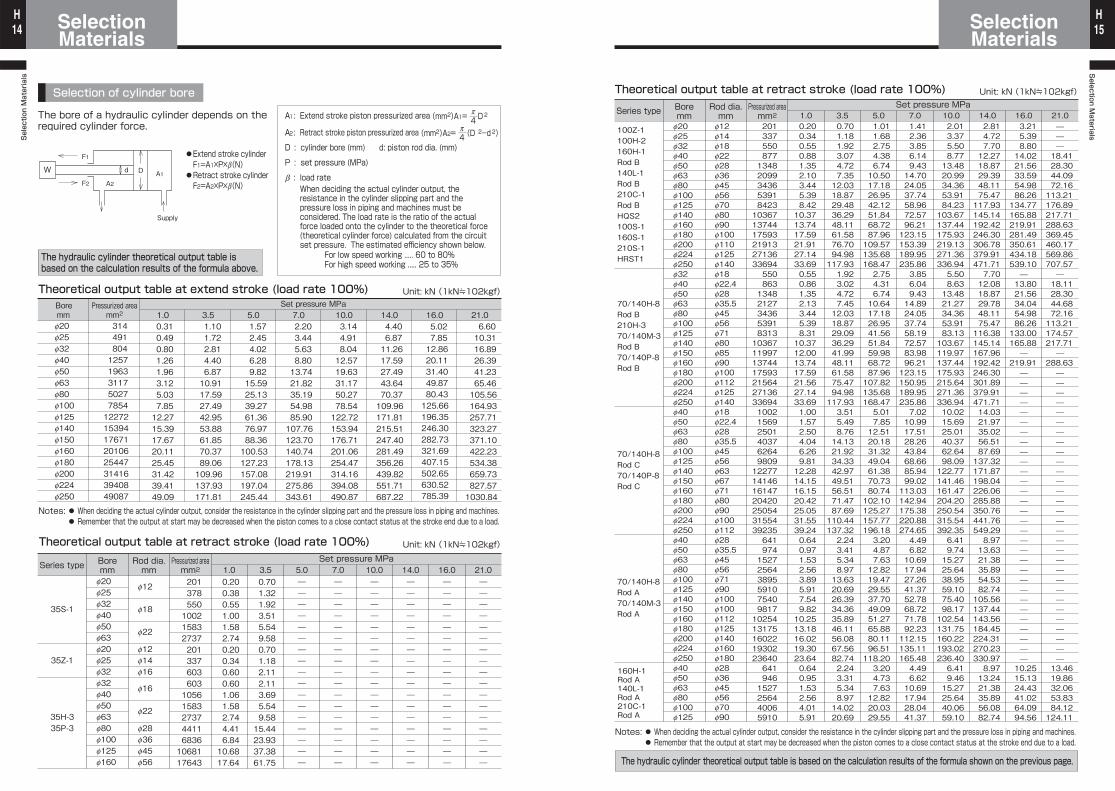
Notes: ● When deciding the actual cylinder output, consider the resistance in the cylinder slipping part and the pressure loss in piping and machines. ● Remember that the output at start may be decreased when the piston comes to a close contact status at the stroke end due to a load.
The bore of a hydraulic cylinder depends on the required cylinder force.
●Extend stroke cylinderF1=A1×P×b(N)
●Retract stroke cylinderF2=A2×P×b(N)
Supply
W d
A2
D A1
F1
F2
(mm2)A1= D 2
(mm2)A2= (D 2-d 2)
p4
p4
Selection of cylinder bore
14.04.406.8711.2617.5927.4943.6470.37109.96171.81215.51247.40281.49356.26439.82551.71687.22
10.03.144.918.0412.5719.6331.1750.2778.54122.72153.94176.71201.06254.47314.16394.08490.87
7.02.203.445.638.8013.7421.8235.1954.9885.90107.76123.70140.74178.13219.91275.86343.61
5.01.572.454.026.289.8215.5925.1339.2761.3676.9788.36100.53127.23157.08197.04245.44
3.51.101.722.814.406.8710.9117.5927.4942.9553.8861.8570.3789.06109.96137.93171.81
1.00.310.490.801.261.963.125.037.8512.2715.3917.6720.1125.4531.4239.4149.09
21.06.6010.3116.8926.3941.2365.46105.56164.93257.71323.27371.10422.23534.38659.73827.571030.84
16.05.027.8512.8620.1131.4049.8780.43125.66196.35246.30282.73321.69407.15502.65630.52785.39
Theoretical output table at retract stroke (load rate 100%)
Series type Boremm
Rod dia.mm
Pressurized areamm2
Set pressure MPa
A1: Extend stroke piston pressurized area
A2: Retract stroke piston pressurized area
D : cylinder bore (mm) d: piston rod dia. (mm)
P : set pressure (MPa)
b : load rate
For low speed working ..... 60 to 80%For high speed working ..... 25 to 35%
The hydraulic cylinder theoretical output table isbased on the calculation results of the formula above.
When deciding the actual cylinder output, the resistance in the cylinder slipping part and the pressure loss in piping and machines must be considered. The load rate is the ratio of the actual force loaded onto the cylinder to the theoretical force (theoretical cylinder force) calculated from the circuit set pressure. The estimated efficiency shown below.
35S-1
35Z-1
35H-335P-3
f20f25f32f40f50f63f20f25f32f32f40f50f63f80f100f125f160
201378550100215832737201337603603105615832737441168361068117643
0.200.380.551.001.582.740.200.340.600.601.061.582.744.416.8410.6817.64
0.701.321.923.515.549.580.701.182.112.113.695.549.5815.4423.9337.3861.75
f12
f18
f22
f12f14f16
f16
f22
f28f36f45f56
1.0 3.5 5.0 7.0 10.0 14.0 16.0 21.0
Theoretical output table at retract stroke (load rate 100%)
Notes: ● When deciding the actual cylinder output, consider the resistance in the cylinder slipping part and the pressure loss in piping and machines. ● Remember that the output at start may be decreased when the piston comes to a close contact status at the stroke end due to a load.
The hydraulic cylinder theoretical output table is based on the calculation results of the formula shown on the previous page.
Series type Boremm
Rod dia.mm
Pressurized areamm2
Set pressure MPaUnit: kN (1kN≒102kgf)
100Z-1100H-2160H-1Rod B140L-1Rod B210C-1Rod BHQS2100S-1160S-1210S-1HRST1
70/140H-8Rod B210H-370/140M-3Rod B70/140P-8Rod B
70/140H-8Rod C70/140P-8Rod C
70/140H-8Rod A70/140M-3Rod A
f20f25f32f40f50f63f80f100f125f140f160f180f200f224f250f32f40f50f63f80f100f125f140f150f160f180f200f224f250f40f50f63f80f100f125f140f150f160f180f200f224f250f40f50f63f80f100f125f140f150f160f180f200f224f250f40f50f63f80f100f125
2013375508771348209934365391842310367137441759321913271363369455086313482127343653918313103671199713744175932156427136336941002156925014037626498091227714146161472042025054315543923564197415272564389559107540981710254131751602219302236406419461527256440065910
0.200.340.550.881.352.103.445.398.4210.3713.7417.5921.9127.1433.690.550.861.352.133.445.398.3110.3712.0013.7417.5921.5627.1433.691.001.572.504.046.269.8112.2814.1516.1520.4225.0531.5539.240.640.971.532.563.895.917.549.8210.2513.1816.0219.3023.640.640.951.532.564.015.91
0.701.181.923.074.727.3512.0318.8729.4836.2948.1161.5876.7094.98117.931.923.024.727.4512.0318.8729.0936.2941.9948.1161.5875.4794.98117.933.515.498.7614.1321.9234.3342.9749.5156.5171.4787.69110.44137.322.243.415.348.9713.6320.6926.3934.3635.8946.1156.0867.5682.742.243.315.348.9714.0220.69
1.011.682.754.386.7410.5017.1826.9542.1251.8468.7287.96109.57135.68168.472.754.316.7410.6417.1826.9541.5651.8459.9868.7287.96107.82135.68168.475.017.8512.5120.1831.3249.0461.3870.7380.74102.10125.27157.77196.183.204.877.6312.8219.4729.5537.7049.0951.2765.8880.1196.51118.203.204.737.6312.8220.0329.55
1.412.363.856.149.4314.7024.0537.7458.9672.5796.21123.15153.39189.95235.863.856.049.4314.8924.0537.7458.1972.5783.9896.21123.15150.95189.95235.867.0210.9917.5128.2643.8468.6685.9499.02113.03142.94175.38220.88274.654.496.8210.6917.9427.2641.3752.7868.7271.7892.23112.15135.11165.484.496.6210.6917.9428.0441.37
2.013.375.508.7713.4820.9934.3653.9184.23103.67137.44175.93219.13271.36336.945.508.6313.4821.2734.3653.9183.13103.67119.97137.44175.93215.64271.36336.9410.0215.6925.0140.3762.6498.09122.77141.46161.47204.20250.54315.54392.356.419.7415.2725.6438.9559.1075.4098.17102.54131.75160.22193.02236.406.419.4615.2725.6440.0659.10
2.814.727.7012.2718.8729.3948.1175.47117.93145.14192.42246.30306.78379.91471.717.7012.0818.8729.7848.1175.47116.38145.14167.96192.42246.30301.89379.91471.7114.0321.9735.0256.5187.69137.32171.87198.04226.06285.88350.76441.76549.298.9713.6321.3835.8954.5382.74105.56137.44143.56184.45224.31270.23330.978.9713.2421.3835.8956.0882.74
3.215.398.8014.0221.5633.5954.9886.26134.77165.88219.91281.49350.61434.18539.1013.8021.5634.0454.9886.26133.00165.88
219.9110.2515.1324.4341.0264.0994.56
18.4128.3044.0972.16113.21176.89217.71288.63369.45460.17569.86707.5718.1128.3044.6872.16113.21174.57217.71
288.6313.4619.8632.0653.8384.12124.11
f12f14f18f22f28f36f45f56f70f80f90f100f110f125f140f18f22.4f28f35.5f45f56f71f80f85f90f100f112f125f140f18f22.4f28f35.5f45f56f63f67f71f80f90f100f112f28f35.5f45f56f71f90f100f100f112f125f140f160f180f28f36f45f56f70f90
1.0 3.5 5.0 7.0 10.0 14.0 16.0 21.0
160H-1Rod A140L-1Rod A210C-1Rod A
Selection Materials
SelectionMaterials16
HSelection M
aterialsSelectionMaterials 17
H
M
M
Notes on piston rod buckling
●Definition of a load when the cylinder stopping method is selected
M
M
In the case of ❶
In the case of ❷
●Definition of load when the external stopping method is selected
~~~~~~~~~~~~~~~~~~~~~~~~~~~~
~~~~~~~~~~~~~~~~~~~~~~~~~~~~~
Calculation of cylinder buckling Calculation of cylinder buckling (use of buckling chart)
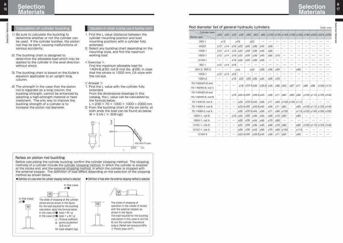
1) Be sure to calculate the buckling to determine whether or not the cylinder can be used. If the cylinder buckles, the piston rod may be bent, causing malfunctions or serious accidents.
2) The buckling chart is designed to determine the allowable load which may be applied to the cylinder in the axial direction without shock.
3) The buckling chart is based on the Euiler's equation applicable to an upright long column.
4) The strength in the case that the piston rod is regarded as a long column, the buckling strength, cannot be enhanced by adopting a high-strength material or heat treatment. The only way to improve the buckling strength of a cylinder is to increase the piston rod diameter.
1. Find the L value (distance between the cylinder mounting position and load mounting position) with a cylinder fully extended.
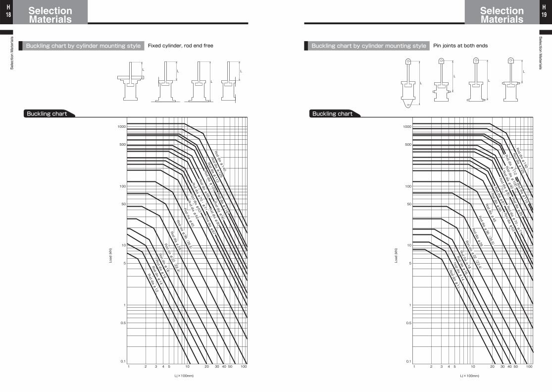
2. Select any buckling chart depending on the mounting style, and find the maximum working load.
< Exercise >Find the maximum allowable load for 140H-8,φ50, rod B (rod dia. φ28), in case that the stroke is 1000 mm, CA style with the rod eye.
< Answer >1. Find the L value with the cylinder fully
extended.From the dimensional drawings in this catalog, the L value can be calculated by the formula below.L = 230 + 70 + 1000 + 1000 = 2300 mm
2. From the buckling chart of the pin joints, at both ends the load can be found as below.W = 3 kN ( ≒ 306 kgf)
Before calculating the cylinder buckling, confirm the cylinder stopping method. The stopping methods of a cylinder include the cylinder stopping method, in which the cylinder is stopped at the stroke end, and the external stopping method, in which the cylinder is stopped with the external stopper. The definition of load differs depending on the selection of the stopping method as shown below.
The state of stopping at the cylinder stroke end as shown in the figure.For the load required for the buckling calculation, apply the formula below.In the case of ❶ : load = M • gIn the case of ❷ : load = µ M • g µ : frictional coefficient g : gravity acceleration 9.8 m/s2 M : load weight (kg)
The state of stopping of operation in the middle of stroke with the external stopper as shown in the figure.The load required for the buckling calculation in this case is not the M, but the cylinder theoretical output (Relief set pressure MPa × Piston area mm2).
~~~~~~~~~~~~~~~~~~~~~~~~~~~~~~~~~~~~~~~~~~~~~~~~~~~~~~~~~~~~~~~~~~~~~~~~~~~~~~~~~~~~~~~~~~~~~~~~~~~~~~~~~~~~
~~~~~~~~~~~~~~~~~~~~~~~~~~~~~~~~~~~~~~~~~~~~~~~~~~~~~~~~~~~~~~~~~~~~~~~~~~~~~~~~~~~~~~~~~~~~~~~~~~~~~~~~~~~~~~~~~~~~~~~~~~~~~~~~~~~~~~~~~~~~~~~~~~~~~~~~~~~~~~~~~~~~~~~~~~~~
~~~~~~~~~~~~~~~~~~~~~~~~~~~~~~~~~~~~~~~~~~~~~~~~~~~~~~~~~~~~~~~~
L
L
3kN
Load
2300
φ50 (Rod B type)
Rod dia (φ28)
mm
Rod diameter list of general hydraulic cylinders
f36
f36
f36
f36
―
―
f36
f28
f35.5
f45
f35.5
f45
f36
f45
f36
f45
f35.5
f28
f28
f28
f28
―
―
f28
f22.4
f28
f35.5
f28
f35.5
f28
f36
f28
f36
f28
f22
f22
f22
f22
―
―
f22
f18
f22.4
f28
f22.4
f28
f22
f28
f22
f28
f22.4
f18
f18
f18
f18
f18
f18
f18
―
f18
―
―
―
f18
―
―
―
―
f16 f22
―
―
―
―
―
―
―
―
―
f112
f140
―
f140
f180
―
―
f140
―
―
―
―
―
―
―
―
―
―
―
f100
f125
―
f125
f160
―
―
f125
―
―
―
―
―
―
―
―
―
―
―
f80
f100
―
f100
f125
―
―
f100
―
―
―
―
―
―
―
―
―
―
―
f90
f112
―
f112
f140
―
―
f110
―
―
―
―
―
―
―
―
―
―
―
f67
f85
f100
―
―
―
―
―
―
―
―
―
―
―
―
―
f56
―
―
f71
f90
f112
f90
f112
f90
―
f90
f110
f90
―
―
―
f70
―
―
f45
―
f70
f56
f71
f90
f71
f90
f70
f90
f70
f90
f71
―
―
―
―
―
―
―
―
―
f63
f80
f100
f80
f100
f80
―
f80
f100
f80
―
f56
f56
f56
―
―
f36
―
f56
f45
f56
f71
f56
f71
f56
f70
f56
f70
f56
f14
f14
f14
―
f14
―
f14
―
―
―
―
―
―
―
―
―
―
―
35S-1
HQS2
100S-1
160S-1
210S-1
35Z-1
35H-3, 35P-3
100Z-1
100H-2
70/140H(P)-8 and
70/140HW-8, rod C
70/140H(P)-8 and
70/140HW-8, rod B
70/140H-8, rod A
70/140M-3, rod B
70/140M-3, rod A
160H-1, rod B
160H-1, rod A
210C-1, rod B
210C-1, rod A
210H-3
f250f63f50f40f32f25
f12
f12
f12
f12
―
f12
―
f12
―
―
―
―
―
―
―
―
―
―
―
f224f200f180f160f150f140f125f100f80
f18 f22
f20
―
f45
f45
f45
f45
―
f28
―
f45
f35.5
f45
f56
f45
f56
f45
f56
f45
f56
f45
Cylinder bore
Series type
Unit: mm
Selection Materials
SelectionMaterials18
HSelection M
aterialsSelectionMaterials 19
H
L L
L
L
1 2 3 4 5 10 20 30 40 50 100
L(×100mm)
1
500
100
50
10
5
0.5
0.1
1000
Rod dia φ112
Rod dia φ125
Rod dia φ140Rod dia φ
100Rod dia φ
110
Rod dia φ90
Rod dia φ85
Rod dia φ45
Rod dia φ56
Rod dia φ63
Rod dia φ67
Rod dia φ80
Rod dia φ36(
35.5)
Rod dia φ28
Rod dia φ22(
22.4)
Rod dia φ18
Rod dia φ16
Rod dia φ14
Rod dia φ12
Buckling chart
Rod dia φ70・
φ71
Load (kN)
Buckling chart by cylinder mounting style Fixed cylinder, rod end free
Buckling chart
Load (kN)
1 2 3 4 5 10 20 30 40 50 100
L(×100mm)
1
500
100
50
10
5
0.5
0.1
1000
Rod dia φ112
Rod dia φ110
Rod dia φ125
Rod dia φ140Rod dia φ
100Rod dia φ
85
Rod dia φ90
Rod dia φ45
Rod dia φ56Rod dia φ
63
Rod dia φ67
Rod dia φ80
Rod dia φ36(
35.5)
Rod dia φ28
Rod dia φ22(
22.4)
Rod dia φ18
Rod dia φ16
Rod dia φ14
Rod dia φ12
Rod dia φ70・
φ71
L
LL
L
Buckling chart by cylinder mounting style Pin joints at both ends
Selection Materials
SelectionMaterials20
HSelection M
aterialsSelectionMaterials 21
H
Buckling chartLoad (kN)
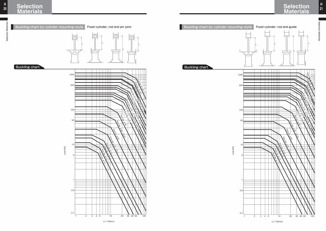
Buckling chart by cylinder mounting style Fixed cylinder, rod end pin joint
L L
L
L
1 2 3 4 5 10 20 30 40 50 100
L(×100mm)
1
500
100
50
10
5
0.5
0.1
1000
Rod dia φ45
Rod dia φ36(
35.5)
Rod dia φ28
Rod dia φ22(
22.4)
Rod dia φ18
Rod dia φ16
Rod dia φ14
Rod dia φ12
Rod dia φ125
Rod dia φ140
Rod dia φ112
Rod dia φ85Rod dia φ
80
Rod dia φ56
Rod dia φ63Rod dia φ
67Rod dia φ
110
Rod dia φ70・
φ71
Rod dia φ90
Rod dia φ100
Buckling chart
Load (kN)
Buckling chart by cylinder mounting style Fixed cylinder, rod end guide
L L
L
L
1 2 3 4 5 10 20 30 40 50 100
L(×100mm)
1
500
100
50
10
5
0.5
0.1
1000
Rod dia φ45
Rod dia φ36(
35.5)
Rod dia φ28
Rod dia φ22(
22.4)
Rod dia φ18
Rod dia φ16
Rod dia φ14
Rod dia φ12
Rod dia φ125
Rod dia φ140
Rod dia φ112
Rod dia φ85Rod dia φ
80
Rod dia φ67
Rod dia φ63
Rod dia φ56
Rod dia φ70・
φ71
Rod dia φ90
Rod dia φ100
Rod dia φ110
Selection Materials
SelectionMaterials22
HSelection M
aterialsSelectionMaterials 23
H
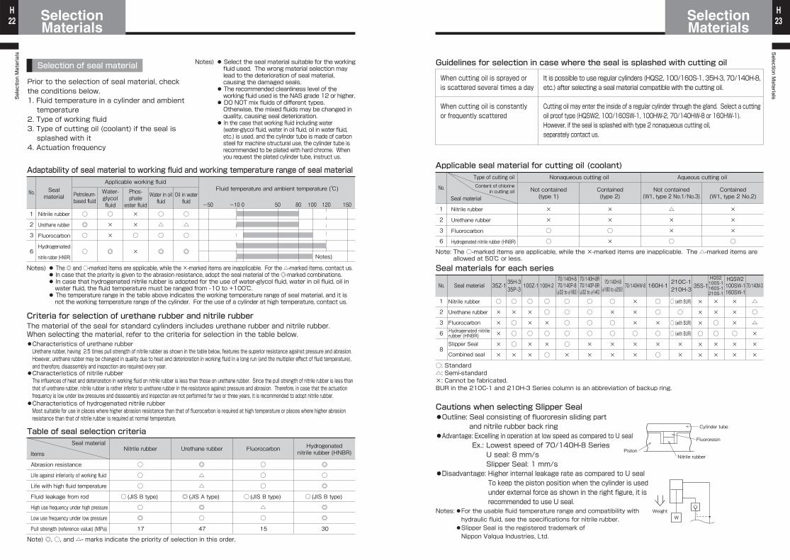
Selection of seal material
Adaptability of seal material to working fluid and working temperature range of seal material
1
2
3
6
Nitrile rubber
Urethane rubber
Fluorocarbon
Hydrogenated
nitrile rubber (HNBR)
Petroleum-based fluid -50 -10 0 50 80 100 120 150
Sealmaterial
Water-glycolfluid
Phos-phateester fluid
Water in oilfluid
Oil in waterfluid
Applicable working fluidFluid temperature and ambient temperature (℃)
○
◎
○
○
○
×
×
◎
×
×
○
×
○
△
○
◎
○
△
○
◎Notes)
No.
Criteria for selection of urethane rubber and nitrile rubberThe material of the seal for standard cylinders includes urethane rubber and nitrile rubber. When selecting the material, refer to the criteria for selection in the table below.●Characteristics of urethane rubber
●Characteristics of nitrile rubber
●Characteristics of hydrogenated nitrile rubber
Abrasion resistance
Life against inferiority of working fluid
Life with high fluid temperature
Fluid leakage from rod
High use frequency under high pressure
Low use frequency under low pressure
Pull strength (reference value) (MPa)
Seal material
Items
Table of seal selection criteria
Nitrile rubber
○
○
○
○ (JIS B type)
○
◎
17
Urethane rubber
◎
△
△
◎ (JIS A type)
◎
○
47
Fluorocarbon
○
○
○
○ (JIS B type)
△
○
15
Hydrogenatednitrile rubber (HNBR)
◎
○
◎
○ (JIS B type)
◎
◎
30
Note) ◎, ○, and △- marks indicate the priority of selection in this order.
Prior to the selection of seal material, check the conditions below.1. Fluid temperature in a cylinder and ambient
temperature2. Type of working fluid3. Type of cutting oil (coolant) if the seal is
splashed with it4. Actuation frequency
Notes) ● Select the seal material suitable for the working fluid used. The wrong material selection may lead to the deterioration of seal material, causing the damaged seals.
● The recommended cleanliness level of the working fluid used is the NAS grade 12 or higher.
● DO NOT mix fluids of different types. Otherwise, the mixed fluids may be changed in quality, causing seal deterioration.
● In the case that working fluid including water (water-glycol fluid, water in oil fluid, oil in water fluid, etc.) is used, and the cylinder tube is made of carbon steel for machine structural use, the cylinder tube is recommended to be plated with hard chrome. When you request the plated cylinder tube, instruct us.
Notes) ● The ◎ and ○-marked items are applicable, while the ×-marked items are inapplicable. For the △-marked items, contact us. ● In case that the priority is given to the abrasion resistance, adopt the seal material of the ◎-marked combinations. ● In case that hydrogenated nitrile rubber is adopted for the use of water-glycol fluid, water in oil fluid, oil in
water fluid, the fluid temperature must be ranged from ‒10 to +100℃. ● The temperature range in the table above indicates the working temperature range of seal material, and it is
not the working temperature range of the cylinder. For the use of a cylinder at high temperature, contact us.
Urethane rubber, having 2.5 times pull strength of nitrile rubber as shown in the table below, features the superior resistance against pressure and abrasion.However, urethane rubber may be changed in quality due to heat and deterioration in working fluid in a long run (and the multiplier effect of fluid temperature), and therefore, disassembly and inspection are required every year.
The influences of heat and deterioration in working fluid on nitrile rubber is less than those on urethane rubber. Since the pull strength of nitrile rubber is less than that of urethane rubber, nitrile rubber is rather inferior to urethane rubber in the resistance against pressure and abrasion. Therefore, in case that the actuation frequency is low under low pressures and disassembly and inspection are not performed for two or three years, it is recommended to adopt nitrile rubber.
Most suitable for use in places where higher abrasion resistance than that of fluorocarbon is required at high temperature or places where higher abrasion resistance than that of nitrile rubber is required at normal temperature.
Guidelines for selection in case where the seal is splashed with cutting oil
It is possible to use regular cylinders (HQS2, 100/160S-1, 35H-3, 70/140H-8, etc.) after selecting a seal material compatible with the cutting oil.
Cutting oil may enter the inside of a regular cylinder through the gland. Select a cutting oil proof type (HQSW2, 100/160SW-1, 100HW-2, 70/140HW-8 or 160HW-1).However, if the seal is splashed with type 2 nonaqueous cutting oil, separately contact us.
When cutting oil is sprayed or is scattered several times a day
When cutting oil is constantly or frequently scattered
Applicable seal material for cutting oil (coolant)
1
2
3
6
Seal material
No.
Nitrile rubber
Urethane rubber
Fluorocarbon
Hydrogenated nitrile rubber (HNBR)
Not contained(type 1)
Contained(type 2)
Not contained(W1, type 2 No.1/No.3)
Contained(W1, type 2 No.2)
Type of cutting oilContent of chlorine
in cutting oil
Aqueous cutting oilNonaqueous cutting oil
×
×
×
○
△
×
×
○
×
×
○
×
×
×
○
○
Note: The ○-marked items are applicable, while the ×-marked items are inapplicable. The △-marked items are allowed at 50℃ or less.
Seal materials for each series
1
2
3
6
8
35Z-1
○
×
×
×
×
×
No. Seal material
Nitrile rubber
Urethane rubber
Fluorocarbon
Slipper Seal
Combined seal
○: Standard△: Semi-standard×: Cannot be fabricated.BUR in the 210C-1 and 210H-3 Series column is an abbreviation of backup ring.
35H-335P-3
70/140H-870/140P-8
(f32 to f160)
70/140H-8(f180 to f250)70/140HW-8
210C-1210H-3 35S-1
HQS2100S-1160S-1210S-1
HQSW2100SW-1160SW-1
70/140M-3
○
×
○
○
○
×
○
○
○
○
○
×
○
○
○
○
×
×
○
×
○
○
×
×
×
×
×
○
×
×
○ (with BUR)
○ (with BUR)
○ (with BUR)
○
×
×
×
×
×
○
×
×
×
×
○
○
×
×
×
×
×
○
×
×
△
○
△
×
×
×
Cautions when selecting Slipper Seal●Outline: Seal consisting of fluororesin sliding part and nitrile rubber back ring
●Advantage: Excelling in operation at low speed as compared to U sealEx.: Lowest speed of 70/140H-8 Series U seal: 8 mm/s Slipper Seal: 1 mm/s
●Disadvantage: Higher internal leakage rate as compared to U seal To keep the piston position when the cylinder is used under external force as shown in the right figure, it is recommended to use U seal.
Notes:●For the usable fluid temperature range and compatibility with hydraulic fluid, see the specifications for nitrile rubber.Slipper Seal is the registered trademark of Nippon Valqua Industries, Ltd.
●
Nitrile rubber
Fluororesin
Cylinder tube
Piston
WWeight
70/140H-8R70/140P-8R(f32 to f140)
160H-1
○
○
×
○
×
○
100Z-1
○
×
×
○
×
×
100H-2
○
○
×
○
×
○
Hydrogenated nitrilerubber (HNBR)
Selection Materials
SelectionMaterials24
HSelection M
aterialsSelectionMaterials 25
H
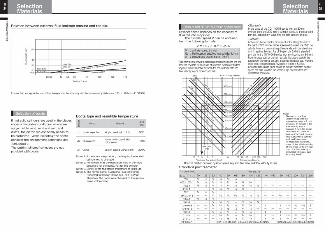
Relation between external fluid leakage amount and rod dia.
External fluid leakage is the total of fluid leakage from the wiper ring with the piston moving distance of 100 m. (Refer to JIS B8367)
Selection of boots
J
JN
JK
Symbols
Name
Nylon tarpaulin
Chloroprene
Conex
HeatProof
80℃
130℃
200℃
Material
Vinyl-coated nylon cloth
Nylon cloth coated with chloroprene
Silicon-coated Conex cloth
Boots type and resistible temperature
0.050.1
0.2
0.3
0.5
Fluid leakage (cm3 )
20 25 40 50 60 80 100 120 140
Rod dia.D (mm)
Nitrile rubber and h
ydrogenated nitrile r
ubber
Urethane rubber
Less than 0.05 cm3
Less than 0.05 cm3
If hydraulic cylinders are used in the places under unfavorable conditions, where are subjected to wind, wind and rain, and dusts, the piston rod especially needs to be protected. When selecting the boots, consider the environment conditions and temperature.The cutting oil proof cylinders are not provided with boots.
Note) 1. If the boots are provided, the length of extended cylinder rod is changed.
Note) 2. Remember that the heat proof field in the table above are for the boots, not for the cylinder.
Note) 3. Conex is the registered trademark of Teijin Ltd.Note) 4. The former name “Neoprene” is a registered
trademark of Showa Denko K.K. and DuPont. Therefore, the name was changed to the general name, chloroprene.
Cylinder speed depends on the capacity of fluid fed into a cylinder. The cylinder speed V can be obtained from the following formula:
V = 1.67 × 10⁴ × Qc/A
Check of port dia. for required on cylinder speed
V : cylinder speed (mm/s)Qc : fluid quantity supplied into cylinder (L/mm)A : pressurized area of piston (mm2)
Standard port diameter
35S-1HQS2・100S-1160S-1210S-135Z-1
35H-3/35P-3100Z-1100H-270/140H-870/140P-8160H-1210C-1210H-370/140M-3
201/81/81/8―1/8―1/8―――――――
251/81/81/8―1/8―1/4―――――――
321/41/41/41/41/81/41/41/43/8―1/4―――
401/41/41/41/4―3/8―3/83/83/83/83/83/8
SSA15
501/41/41/41/4―3/8―3/81/21/21/21/21/2
SSA15
631/41/41/41/4―3/8―1/21/21/21/21/21/2
SSA15
80―3/83/83/8―1/2―1/23/43/43/43/43/4
SSA20
100―3/83/8――1/2―3/43/43/43/43/43/4
SSA20
125――1/2――1/2―3/41―111
SSA25
140――――――――1―111
SSA25
150――――――――1―――――
160―――――3/4――1―111
SSA25
180――――――――11/4――11/4―
SSA32
200――――――――11/2――11/2―
SSA40
224――――――――11/2――11/2―
SSA40
250――――――――2――2―
SSA50
Bore (mm)
Series
Port dia. Rc
The chart below shows the relation between the speed and the required flow rate for each size of standard hydraulic cylinders (cylinder inside) and that between the required flow rate and flow velocity in pipe for each port dia.
< Example >In the case of the 70/140H-8 series with an 80 mm cylinder bore and 300 mm/s cylinder speed, is the standard port dia. applicable? Also, find the flow velocity in pipe.< Answer >In the chart below, find the cross point of the straight line from the point of 300 mm/s cylinder speed and the slant line of 80 mm cylinder bore, and draw a straight line parallel with the lateral axis until it reaches the slant line of the port dia. 3/4 (the standard port dia. for the 70/140H-8 series with a cylinder bore of 80 mm).From the cross point on the slant port dia. line, draw a straight line parallel with the vertical axis until it reaches the lateral axis. From the cross point, the correspondig flow velocity in pipe is 5.2 m/s.Since the cross point found based on the port diameter, cylinder speed and bore is within the usable range, the standard port diameter is applicable.
Note)The appropriate flow velocity in pipe for the appropriate range is 7 m/s or below. In general, if the flow velocity in pipe exceeds 7 m/s, the piping resistance and pressure loss are increased, causing less output during cylinder work and lower speed.To reduce pressure loss, adopt piping with larger dia. of one grade to the cylinder port. The flow velocity is calculated with steel tube for piping Sch80.
Appropriaterange
Chart of relation between cylinder speed, required flow rate, and flow velocity in pipePipe inside flow velocity (m/s)
Fluid capacity required
Cylinder speed (mm/s)10 7 5 3 2 1 0 50 70 100 200 300 500
100r/min
200r/min
400r/min
40r/min50r/min
30r/min
20r/min
10r/min
5r/min
50A
32A25A
15A20A
40A
φ250
φ160
φ140
φ180
φ125
φ150
φ100
φ200
φ224
φ40
φ32
φ25
φ20
φ50
φ63
φ80
2B (Pipe bore) (φ49.5)
1 B(φ38.4)
1/21/41 B(φ32.9)
1B(φ25) 3/4 B(φ
19.4)
1/2 B (φ14.3)
3/8 B(φ10.9)1/4 B(φ
7.8) 1/8 B(φ5.7)
Selection Materials
SelectionMaterials26
HSelection M
aterialsSelectionMaterials 27
H
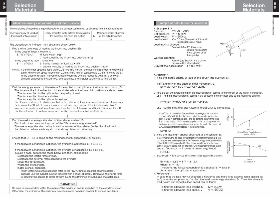
Maximum energy absorbed by cylinder cushion
The conditions of absorbed energy allowable for the cylinder cushion can be obtained from the formula below.
The procedures to find each item above are shown below.
≦+E2 Et
CAUTION
Find the inertia energy of load at the inrush into cushion, E1. In the case of linear movement: E1=MV2/2 (J) M: load weight (kg)
V: load speed at the inrush into cushion (m/s) In the case of rotation movement: E1=!ω2/2 (J) !: inertia moment of load (kg • m2)
ω: angular velocity of load at the inrush into cushion (rad/s)Notes:
Inertia energy of load atthe inrush into cushion
Energy generated by the external force applied tothe cylinder at the inrush into cushion
Maximum energy absorbedof the cylinder cushion
E1
Find the energy generated by the external force applied to the cylinder at the inrush into cushion, E2. The forces acting in the direction of the cylinder axis at the inrush into cushion are shown below. ・The force applied to the cylinder by the gravity of load ・The force applied by other cylinders ・The force applied to the cylinder by springs
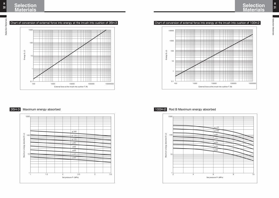
Find the maximum energy absorbed of the cylinder cushion, Et.Find it with the corresponding chart of the “Maximum energy absorbed”.The max. energy absorbed during forward movement of the cylinder (in the direction in which the piston rod advances) is equal to that during piston rod retracting.
Ensure that E1 + E2 is same as the maximum energy absorbed Et, or smaller.
If the following condition is satisfied, the cylinder is applicable: E1 + E2 ≦ Et.
If the following condition is satisfied, the cylinder is inapplicable: E1 + E2 ≧ Et.In such a case, perform the steps below, and then, select again. ・Decrease the inertia force of load. ・Decrease the external force applied to the cylinder. ・Lower the set pressure. ・Widen the cylinder bore. ・Install a shock absorber.
↓
↓
↓
If the cylinder speed is less than 0.08 m/s (80 mm/s), the cushioning effect is weakened.Even if the cylinder speed is less than 0.08 m/s (80 mm/s), suppose it is 0.08 m/s to find the E1.In the case of rotation movement, even when the cylinder speed is 0.08 m/s or lower, similarly suppose it is 0.08 m/s, and calculate the angular velocity ω to find the E1.
Find the external force F, which is applied to the cylinder at the inrush into cushion, and the energy E2 by using the “Chart of conversion of external force into energy at the inrush into cushion”.In case that such an external force is not applied, the following condition is satisfied: E2 = 0.For the selection of cushion, suppose that the frictional resistance of load is 0.
When installing a shock absorber, refer to the “TAIYO Shock absorber general catalog”.DO NOT use the cylinder cushion together with a shock absorber. Otherwise, the inertia force of load may be applied to either of them due to the difference of cushioning characteristics.
Be sure to use cylinders within the range of the maximum energy absorbed of the cylinder cushion.Otherwise, the cylinder or the peripheral devices may be damaged, leading to serious accidents.
Example of calculation for selection
< Answer >1. Find the inertia energy of load at the inrush into cushion, E1.
Inertia energy in the case of linear movement, E1E1 = MV2/2 = 500 × 0.32/2 = 22.5J
2. Find the E2, energy generated by the external force F, applied to the cylinder at the inrush into cushion.2.1 Find the external force F, applied in the direction of the cylinder axis at the inrush into cushion.
F=Mgsin θ =500×9.8×sin30˚ =2450N
2.2 Convert the external force F, found in the step 2.1, into the energy E2.
E2=8.7J3. Find the maximum energy absorbed of the cylinder, Et.
Et=44J4. Ensure that E1 + E2 is same as the maximum energy absorbed Et, or smaller.
E1 + E2 = 22.5 + 8.7 = 31.2Jwhere, Et = 44JTherefore, the following condition is satisfied: E1 + E2 ≦ EtAs a result, the cylinder is applicable.
< Reference >
To find the allowable load weight, M M = 2Et/V2
To find the allowable load speed, V V = 2Et/M√
θ
Mg sinθ
θ=30°
Mg
8.7J
2450 NExternal force F applied during
cushion stroke
φ6344J
5MPaSet pressure P1
In the “Chart of conversion of external force into energy at the inrush into cushion of 70/140H-8”, find the cross point of the straight line from the point of 2450 N on the lateral axis F and the slant line shown in the chart. Then, draw a straight line from the cross point on the slant line parallel with the lateral axis until it reaches the vertical axis of the chart. The cross point 8.7 J, indicates the energy applied by the external force.
In the right chart, find the cross point of the straight line from the point of 5 MPa on the lateral axis, the set pressure of the “Maximum energy absorbed of cushion” of the 70H-8 and the curve of φ63. Then, draw a straight line from the cross point on the curve parallel with the lateral axis until it reaches the vertical axis of the chart. The cross point, 44 J, indicates the maximum energy absorbed.
In case that the load moving direction is horizontal and there is no external force applied (E2 = 0), from the set pressure, first find the maximum energy absorbed, Et. Then, the allowable load weight and allowable load speed can be found.
< Example 1 >Cylinder 70H-8⦆⦆⦆φ63Set pressure P1 = 5 MPaLoad weight M = 500 kgLoad speed V = 0.3 m/s (the speed at the inrush into cushion is 300 mm/s) Load moving direction Downward θ = 30° (there is no external force applied to the cylinder other than gravity)Working direction Forward (the direction of the piston rod ejected from the cylinder)Gravitational acceleration g = 9.8 m/s2
Maximum energy
absorbed Et
Energy E2
Selection Materials
SelectionMaterials28
HSelection M
aterialsSelectionMaterials 29
H
Rack and pinion
D
φ6344J
5 MPaSet pressure P1
In the right chart, find the cross point of the straight line from the point of 5 MPa on the lateral axis, the supply pressure of the “maximum energy absorbed of cushion” of the 70H-8 and the curve of φ63 bore. Then, draw a straight line from the cross point on the curve parallel with the lateral axis until it reaches the vertical axis of the chart. The cross point 44 J, indicates the maximum energy absorbed.
< Reference >
To find the allowable load inertia moment,!To find the allowable load angular velocity, ω
In case of the rotation movement, of which load moving direction is horizontal, without an external force (E2 = 0), from the set pressure, first find the maximum energy absorbed, Et. Then, the allowable inertia moment and allowable load angular velocity can be found.
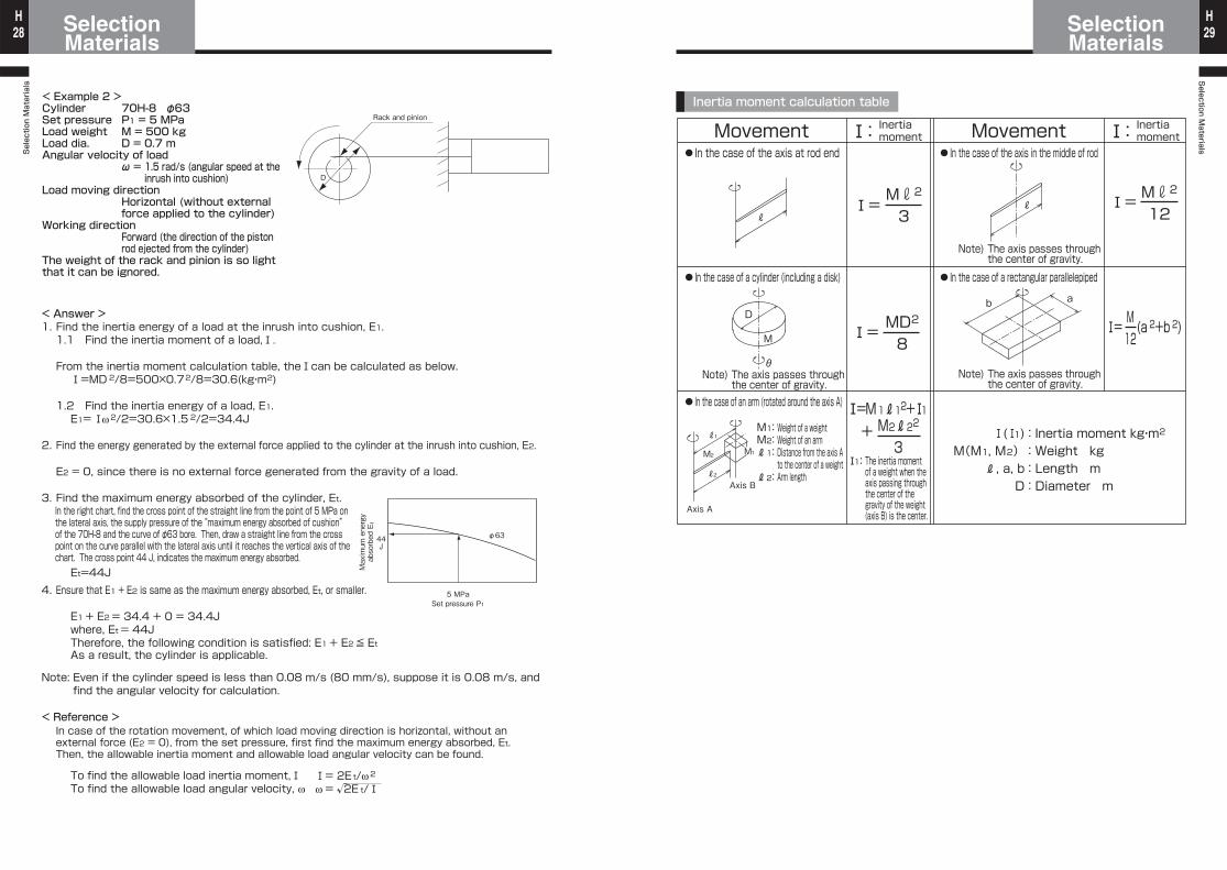
< Example 2 >Cylinder 70H-8⦆⦆φ63Set pressure P1 = 5 MPaLoad weight M = 500 kgLoad dia. D = 0.7 mAngular velocity of load ω = 1.5 rad/s (angular speed at the inrush into cushion)Load moving direction Horizontal (without external force applied to the cylinder)Working direction Forward (the direction of the piston rod ejected from the cylinder)The weight of the rack and pinion is so light that it can be ignored.
< Answer >1. Find the inertia energy of a load at the inrush into cushion, E1.
1.1 Find the inertia moment of a load,!.
From the inertia moment calculation table, the!can be calculated as below.!=MD2/8=500×0.72/8=30.6(kg・m2)
1.2 Find the inertia energy of a load, E1.E1=!ω 2/2=30.6×1.5 2/2=34.4J
2. Find the energy generated by the external force applied to the cylinder at the inrush into cushion, E2.
E2 = 0, since there is no external force generated from the gravity of a load.
3. Find the maximum energy absorbed of the cylinder, Et.
Et=44J4. Ensure that E1 + E2 is same as the maximum energy absorbed, Et, or smaller.
E1 + E2 = 34.4 + 0 = 34.4Jwhere, Et = 44J Therefore, the following condition is satisfied: E1 + E2 ≦ EtAs a result, the cylinder is applicable.
Note: Even if the cylinder speed is less than 0.08 m/s (80 mm/s), suppose it is 0.08 m/s, and find the angular velocity for calculation.
!= 2Et/ω 2
ω= 2E t/!√
Maximum energy
absorbed Et
Inertia moment calculation table
Movement Movement●In the case of the axis at rod end
●In the case of a cylinder (including a disk)
●In the case of the axis in the middle of rod
●In the case of a rectangular parallelepiped
!1:
●In the case of an arm (rotated around the axis A)
!(!1) M(M1, M2)
R, a, b D
: Inertia moment kg・m2
: Weight kg : Length m : Diameter m
Inertia moment!: Inertia
moment!:
!= Mr2
3
!= MD2
8
!=M1R12+!1+ M2R22
3
!= Mr2
12
!= (a 2+b 2)M 12
M1: M2: R1:
R2:
RR
D
M
θ
b a
M2
Axis B
Axis A
M1
R1
R2
Note) The axis passes through the center of gravity.
Note) The axis passes through the center of gravity.
Note) The axis passes through the center of gravity.
The inertia moment of a weight when the axis passing through the center of the gravity of the weight (axis B) is the center.
Weight of a weightWeight of an armDistance from the axis A to the center of a weightArm length
Selection Materials
SelectionMaterials30
HSelection M
aterialsSelectionMaterials 31
H
Chart of conversion of external force into energy at the inrush into cushion of 35H-3
35H-3 Maximum energy absorbed
1000
0.1
1
100
10
100 1000 10000 100000 10000000
1000
100
10
11 1.5 2 2.5 3 3.5
φ32
φ40
φ50
φ63
φ80
φ100
φ125
φ160
External force at the inrush into cushion F (N)
Ene
rgy
E2
(J)
Set pressure P1 (MPa)
Max
imum
ene
rgy
abso
rbed
Et (
J)Chart of conversion of external force into energy at the inrush into cushion of 100H-2
100H-2 Rod B Maximum energy absorbed
1000
1
100
10
2 4 6 8 10
φ100
φ125
φ80
φ63
φ50
φ40
φ32
100 1000 10000 100000 1000000
10000
1000
100
10
1
0.1
External force at the inrush into cushion F (N)
Ene
rgy
E2
(J)
Set pressure P1 (MPa)
Max
imum
ene
rgy
abso
rbed
Et (
J)
Selection Materials
SelectionMaterials32
HSelection M
aterialsSelectionMaterials 33
H
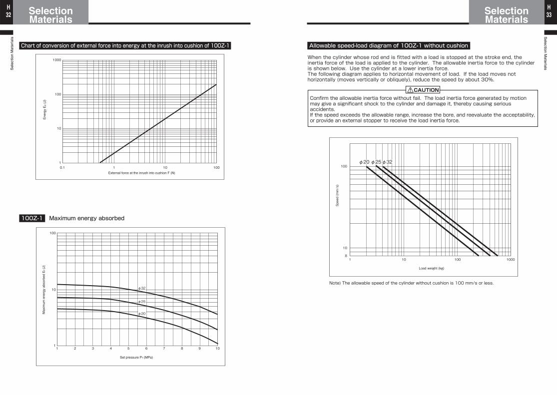
Chart of conversion of external force into energy at the inrush into cushion of 100Z-1
100Z-1 Maximum energy absorbed
1000
1
100
10
0.1 1 10 100
100
1
10
1 2 3 4 5 6 7 8 9 10
φ32
φ25
φ20
External force at the inrush into cushion F (N)
Ene
rgy
E2
(J)
Set pressure P1 (MPa)
Max
imum
ene
rgy
abso
rbed
Et (
J)
CAUTION
Allowable speed-load diagram of 100Z-1 without cushion
Note) The allowable speed of the cylinder without cushion is 100 mm/s or less.
1 10 100 1000
φ25φ25φ25φ25
10
100
8
Load weight (kg)
Speed (mm/s)
φ32φ32φ20φ20φ20φ20 φ32φ25φ25φ25φ20φ20φ20
When the cylinder whose rod end is fitted with a load is stopped at the stroke end, the inertia force of the load is applied to the cylinder. The allowable inertia force to the cylinder is shown below. Use the cylinder at a lower inertia force.The following diagram applies to horizontal movement of load. If the load moves not horizontally (moves vertically or obliquely), reduce the speed by about 30%.
Confirm the allowable inertia force without fail. The load inertia force generated by motion may give a significant shock to the cylinder and damage it, thereby causing serious accidents.If the speed exceeds the allowable range, increase the bore, and reevaluate the acceptability, or provide an external stopper to receive the load inertia force.
Selection Materials
SelectionMaterials34
HSelection M
aterialsSelectionMaterials 35
H
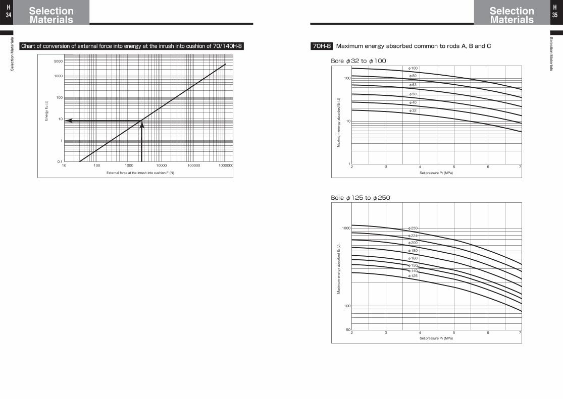
Chart of conversion of external force into energy at the inrush into cushion of 70/140H-8
External force at the inrush into cushion F (N)
Ene
rgy
E2
(J)
1000
5000
0.1
1
10
100
100000 10000001000010 100 1000
70H-8 Maximum energy absorbed common to rods A, B and C
Bore φ32 to φ100
Bore φ125 to φ250
100
1
10
2 3 4 5 6 7
φ100
φ80
φ63
φ50
φ40
φ32
1000
50
100
2 3 4 5 6 7
φ250
φ224
φ200
φ180
φ160
φ125
φ150φ140
Set pressure P1 (MPa)M
axim
um e
nerg
y ab
sorb
ed E
t (J)
Set pressure P1 (MPa)
Max
imum
ene
rgy
abso
rbed
Et (
J)
Selection Materials
SelectionMaterials36
HSelection M
aterialsSelectionMaterials 37
H
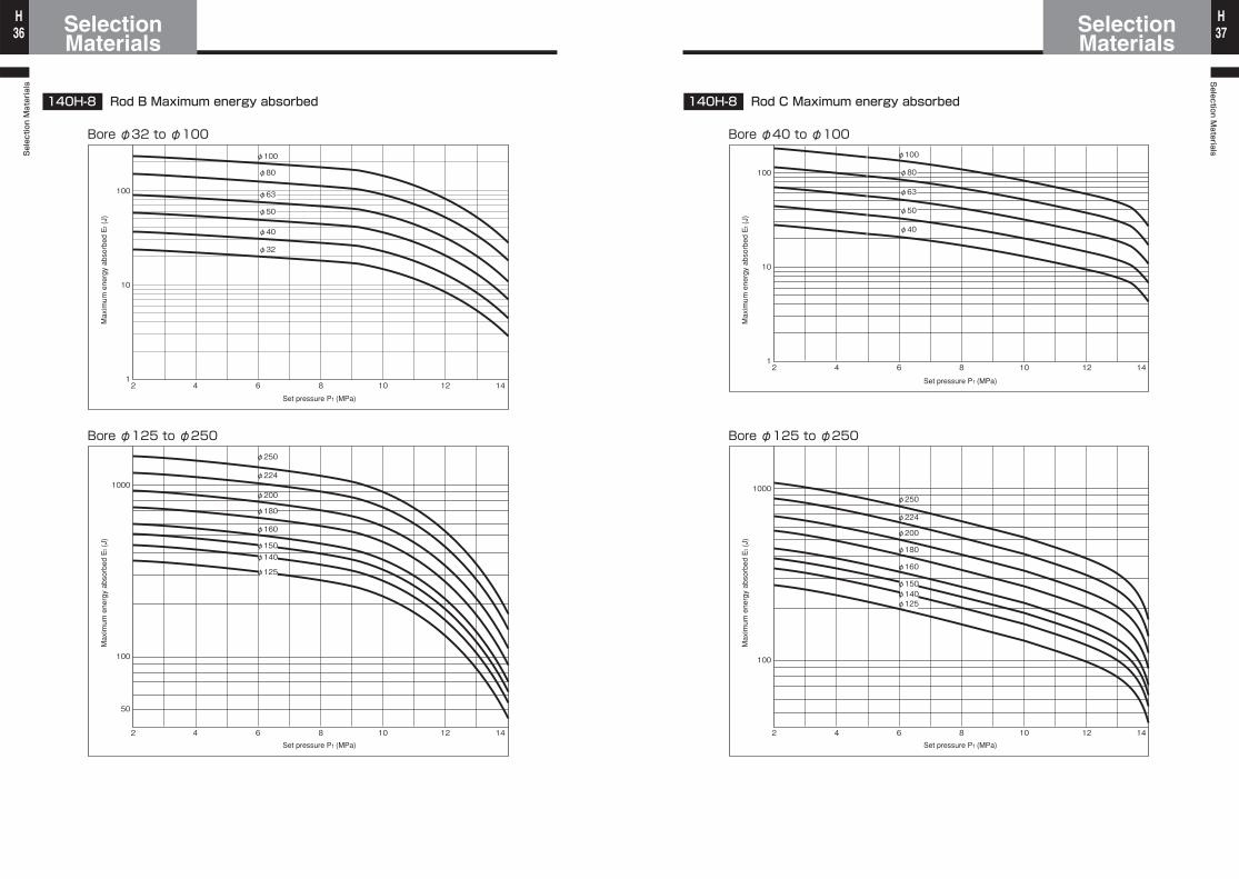
140H-8 Rod B Maximum energy absorbed
Bore φ32 to φ100
Bore φ125 to φ250
Set pressure P1 (MPa)
Max
imum
ene
rgy
abso
rbed
Et (
J)
Set pressure P1 (MPa)
Max
imum
ene
rgy
abso
rbed
Et (
J)
100
1
10
2 4 6 8 10 1412
φ100
φ80
φ63
φ50
φ40
φ32
2 4 6 8 10 1412
1000
50
100
φ250
φ224
φ200
φ180
φ160
φ125
φ140φ150
140H-8 Rod C Maximum energy absorbed
Bore φ40 to φ100
Bore φ125 to φ250
Set pressure P1 (MPa)M
axim
um e
nerg
y ab
sorb
ed E
t (J)
Set pressure P1 (MPa)
Max
imum
ene
rgy
abso
rbed
Et (
J)
100
1
10
φ100
φ63
φ50
φ40
2 4 6 8 10 12 14
φ80
1000
100
2 4 6 8 10 12 14
φ250
φ224
φ200
φ180
φ160
φ140φ125
φ150
Selection Materials
SelectionMaterials38
HSelection M
aterialsSelectionMaterials 39
H
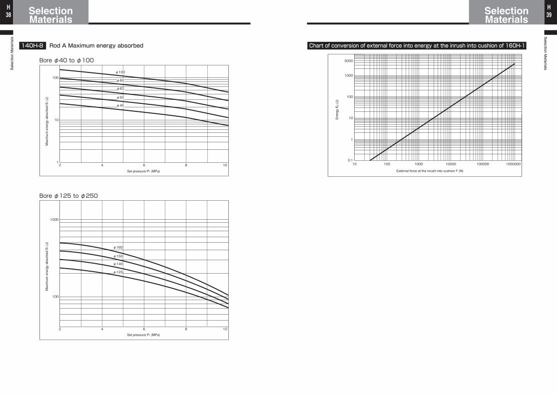
140H-8 Rod A Maximum energy absorbed
Bore φ40 to φ100
Bore φ125 to φ250
Set pressure P1 (MPa)
Max
imum
ene
rgy
abso
rbed
Et (
J)
Set pressure P1 (MPa)
Max
imum
ene
rgy
abso
rbed
Et (
J)
100
1
10
2 4 6 8 10
φ63
φ50
φ40
φ80
φ100
1000
100
2 4 6 8 10
φ125
φ140
φ150
φ160
Chart of conversion of external force into energy at the inrush into cushion of 160H-1
External force at the inrush into cushion F (N)
Ene
rgy
E2
(J)
1000
5000
0.1
1
10
100
100000 10000001000010 100 1000
Selection Materials
SelectionMaterials40
HSelection M
aterialsSelectionMaterials 41
H
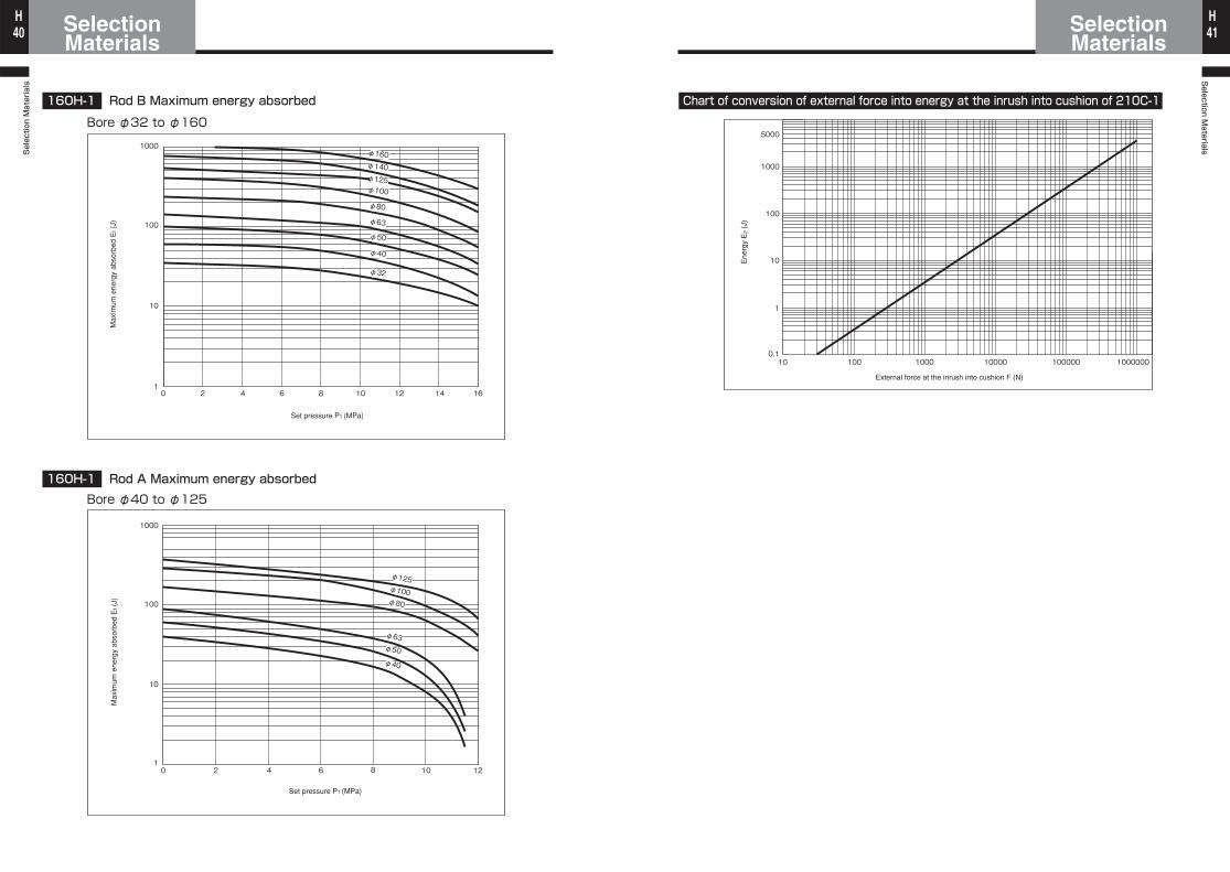
160H-1 Rod B Maximum energy absorbed
Bore φ32 to φ160
160H-1 Rod A Maximum energy absorbedBore φ40 to φ125
Set pressure P1 (MPa)
Max
imum
ene
rgy
abso
rbed
Et (
J)
Set pressure P1 (MPa)
Max
imum
ene
rgy
abso
rbed
Et (
J)
φ32
φ40
φ50
φ63
φ80
φ100
φ125
φ140
φ160
100
1000
1
10
0 2 4 6 8 10 12 14 16
100
1000
1
10
0 2 4 6 8 10 12
φ40
φ50
φ63
φ80
φ100
φ125
Chart of conversion of external force into energy at the inrush into cushion of 210C-1
External force at the inrush into cushion F (N)
Ene
rgy
E2
(J)
1000
5000
0.1
1
10
100
100000 10000001000010 100 1000
Selection Materials
SelectionMaterials42
HSelection M
aterialsSelectionMaterials 43
H
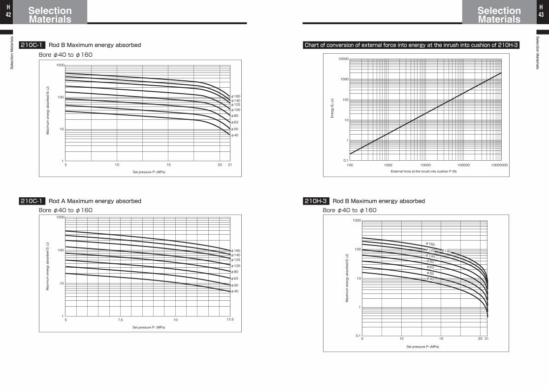
210C-1 Rod B Maximum energy absorbed
Bore φ40 to φ160
210C-1 Rod A Maximum energy absorbedBore φ40 to φ160
Set pressure P1 (MPa)
Max
imum
ene
rgy
abso
rbed
Et (
J)
Set pressure P1 (MPa)
Max
imum
ene
rgy
abso
rbed
Et (
J)
1000
1
10
100
5 10 15 20 21
φ160φ140φ125φ100
φ80
φ63
φ50
φ40
1000
1
10
100
5 7.5 10 12.5
φ125
φ100
φ160φ140
φ80
φ63
φ50
φ40
Chart of conversion of external force into energy at the inrush into cushion of 210H-3
External force at the inrush into cushion F (N)
Ene
rgy
E2
(J)
210H-3 Rod B Maximum energy absorbedBore φ40 to φ160
Set pressure P1 (MPa)M
axim
um e
nerg
y ab
sorb
ed E
t (J)
10000
0.1
1
1000
100
10
100 1000 10000 100000 10000000
100
1000
0.1
1
10
5 10 15 2120
φ40
φ50
φ63
φ80
φ100
φ125 φ140
φ160
Selection Materials
SelectionMaterials44
HSelection M
aterialsSelectionMaterials 45
H
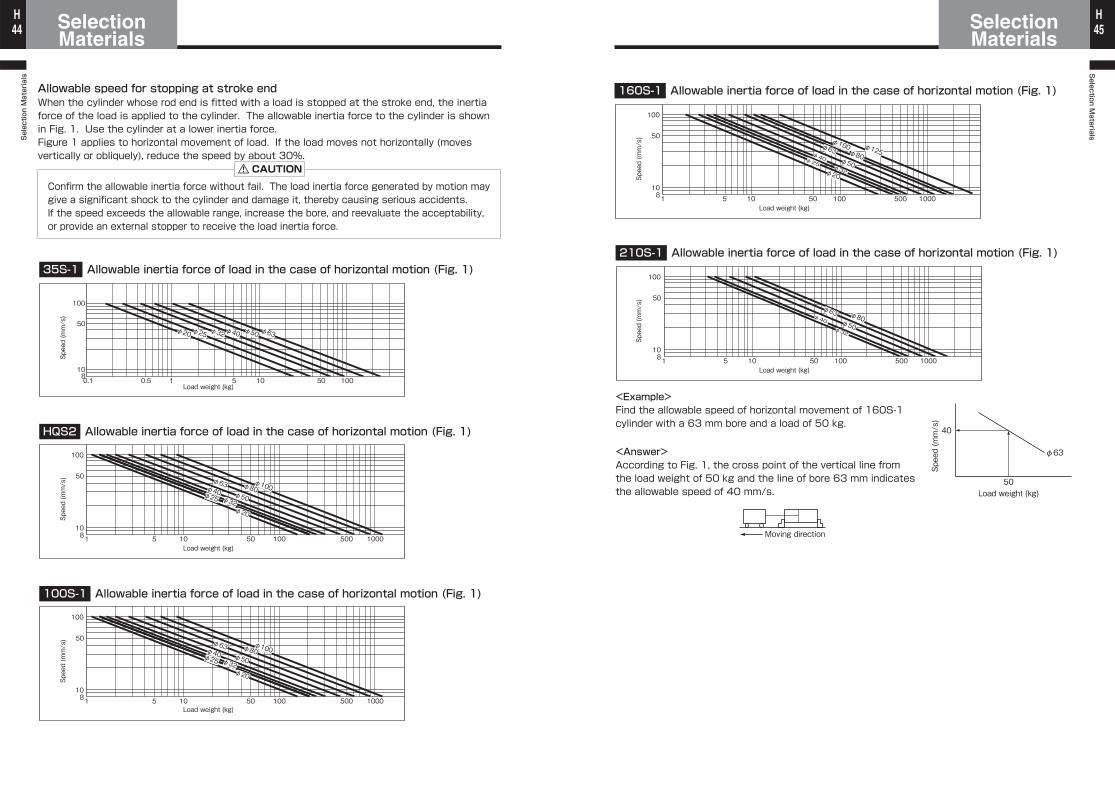
35S-1 Allowable inertia force of load in the case of horizontal motion (Fig. 1)
100S-1 Allowable inertia force of load in the case of horizontal motion (Fig. 1)
Allowable speed for stopping at stroke end
CAUTION
HQS2 Allowable inertia force of load in the case of horizontal motion (Fig. 1)
5810
50
100
10.50.1 10 50 100
φ25φ20 φ63φ32 φ50φ40
50810
100
1051 100 500 1000
50φ80φ100
φ50φ32φ20
φ63φ40φ25
50810
100
1051 100 500 1000
50φ80φ100
φ50φ32φ20
φ63φ40φ25φ25
When the cylinder whose rod end is fitted with a load is stopped at the stroke end, the inertia force of the load is applied to the cylinder. The allowable inertia force to the cylinder is shown in Fig. 1. Use the cylinder at a lower inertia force.Figure 1 applies to horizontal movement of load. If the load moves not horizontally (moves vertically or obliquely), reduce the speed by about 30%.
Confirm the allowable inertia force without fail. The load inertia force generated by motion may give a significant shock to the cylinder and damage it, thereby causing serious accidents.If the speed exceeds the allowable range, increase the bore, and reevaluate the acceptability, or provide an external stopper to receive the load inertia force.
Load weight (kg)
Load weight (kg)
Load weight (kg)
Speed (mm/s)
Speed (mm/s)
Speed (mm/s)
Allowable inertia force of load in the case of horizontal motion (Fig. 1)
Allowable inertia force of load in the case of horizontal motion (Fig. 1)
160S-1
<Example>Find the allowable speed of horizontal movement of 160S-1 cylinder with a 63 mm bore and a load of 50 kg.
<Answer>According to Fig. 1, the cross point of the vertical line from the load weight of 50 kg and the line of bore 63 mm indicates the allowable speed of 40 mm/s.
210S-1
50810
100
1051 100 500 1000
50
φ80
φ100 φ125φ50φ32φ20
φ63φ40φ25
50810
100
1051 100 500 1000
50
φ80φ50φ32
φ63φ40
φ63
40
50Load weight (kg)
Moving direction
Load weight (kg)
Load weight (kg)
Speed (mm/s)
Speed (mm/s)
Speed (mm/s)


