

HAND HELD HYDRAULIC TOOLPRODUCT CATALOG
HH 1002015-2016
www.stanleyhydraulic.comwww.StanleyHydraulics.com

www.stanleyhydraulics.com www.stanleyhydraulics.com2
Stanley Hydraulic Tools has a proud tradition of being a global leader in the development of a wide range of innovative hydraulic products used in a variety of industries and applications throughout the world. As a proud member of Stanley Black & Decker, a 165 year old company committed to the manufacture and distribution of quality tools for the professional, industrial, and consumer, we at Stanley Hydraulic Tools are dedicated to providing our customers with innovative customer-driven product designs, world class quality, unmatched product support, and superior value.
In 1984, Stanley Black & Decker purchased HED, Inc., the largest U.S. manufacturer of mounted hydraulic breakers and compactors, and integrated HED’s product line, design and manufacturing expertise with the Hydraulic Tools Product Group.
Today, Stanley Hydraulic Tools is the world’s largest hand held hydraulic tool manufacturer and world-wide market leader offering over 150 hand held hydraulic tools and over 30 mounted impact tools. Further, we’re the only US manufacturer of mounted Hydraulic Breakers.
HAND HELD HYDRAULIC TOOLS
COMPANY OVERVIEW
CERTIFICATIONS
GREAT BRAND GREAT TOOLS
GLOBAL REPRESENTATION
Stanley Hydraulic Tools produces an extensive line of products for use in construction, demolition, scrap processing, recycling, utilities, municipalities, railroads, industry, landscaping, underwater construction, and specialty trades in two North American manufacturing facilities. Additionally, Stanley Hydraulic Tools has sales offices and distributors throughout North America, Central America, South America, Europe, Asia, Australia, and the Middle East.
OUR GOAL
Stanley Hydraulic Tools is committed to being a “great brand” through continuous innovation, excellence, quality, value and service.
www.stanleyhydraulics.com www.stanleyhydraulics.com 3
HAND HELD HYDRAULIC TOOLS
INDEX
CATALOG INDEX
All Stanley tools, accessories, parts and allied equipment are subject to design improvements, specification and price changes at any time without notice and with no obligation to units already sold. Weights, dimensions and operating specifications listed herein are subject to change without notice. Where specifications are critical to your application, please consult the factory.
WHY HYDRAULICS . . . . . . . . . . . . . . . . . . . . . . . . . . . . . . . . 4
PERCUSSION TOOLS . . . . . . . . . . . . . . . . . . . . . . . . . . . 5-11
Breakers . . . . . . . . . . . . . . . . . . . . . . . . . . . . . . . . . . . . . 5-7
Chipping Hammers . . . . . . . . . . . . . . . . . . . . . . . . . . . . . . 8
Digger . . . . . . . . . . . . . . . . . . . . . . . . . . . . . . . . . . . . . . . . . 9
Drivers & Pullers . . . . . . . . . . . . . . . . . . . . . . . . . . . . 9-11
Tampers . . . . . . . . . . . . . . . . . . . . . . . . . . . . . . . . . . . . 11-12
EARTH AUGER . . . . . . . . . . . . . . . . . . . . . . . . . . . . . . . . . . . 12
CUTTING & TRIMMING TOOLS . . . . . . . . . . . . . . . . . 13-19
Cut-Off Saws . . . . . . . . . . . . . . . . . . . . . . . . . . . . . . . . . . 13
Wood-Cutting Chain Saws . . . . . . . . . . . . . . . . . . . 14-15
Concrete-Cutting Chain Saws . . . . . . . . . . . . . . . . 16-17
Ductile Iron Pipe Saw & Pump . . . . . . . . . . . . . . . . . . 18
Circular Saw & Pruners . . . . . . . . . . . . . . . . . . . . . . . . 19
GRINDERS . . . . . . . . . . . . . . . . . . . . . . . . . . . . . . . . . . . . . . . 20
WRENCHES & DRILLS . . . . . . . . . . . . . . . . . . . . . . . . . 21-28
Impact Wrenches & Drills . . . . . . . . . . . . . . . . . . . 22-24
Hydrant Saver . . . . . . . . . . . . . . . . . . . . . . . . . . . . . . . . . 25
Hammer Drills . . . . . . . . . . . . . . . . . . . . . . . . . . . . . . . . . 26
Sinker Drills . . . . . . . . . . . . . . . . . . . . . . . . . . . . . . . . . . . 27
Core Drills . . . . . . . . . . . . . . . . . . . . . . . . . . . . . . . . . . . . . 28
SUBMERSIBLE PUMPS . . . . . . . . . . . . . . . . . . . . . . . . 29-30
VENT FAN . . . . . . . . . . . . . . . . . . . . . . . . . . . . . . . . . . . . . . . 31
POWER UNITS . . . . . . . . . . . . . . . . . . . . . . . . . . . . . . . 32-36
TWIN 8 . . . . . . . . . . . . . . . . . . . . . . . . . . . . . . . . . . . . . 32-33
GT18 . . . . . . . . . . . . . . . . . . . . . . . . . . . . . . . . . . . . . . . . . . 34
GT23 . . . . . . . . . . . . . . . . . . . . . . . . . . . . . . . . . . . . . . . . . . 34
TracHorse . . . . . . . . . . . . . . . . . . . . . . . . . . . . . . . . . . . . . 35
Hydraverter . . . . . . . . . . . . . . . . . . . . . . . . . . . . . . . . . . . 35
ACCESSORIES . . . . . . . . . . . . . . . . . . . . . . . . . . . . . . . . . . . 37
HYDRAULIC SYSTEM REQUIREMENTS . . . . . . . . . . . . 38
HYDRAULIC BASICS . . . . . . . . . . . . . . . . . . . . . . . . . . . . . 39
Hose Types . . . . . . . . . . . . . . . . . . . . . . . . . . . . . . . . . . . . 40
Hose Recommendations . . . . . . . . . . . . . . . . . . . . . . . . 40
Recommended Hydraulic Fluids . . . . . . . . . . . . . . . . 41
SYSTEM SPECIFICATIONS . . . . . . . . . . . . . . . . . . . . . 42-46
HTMA Type I Hydraulic Systems . . . . . . . . . . . . . . . . 42
HTMA Type II Hydraulic Systems . . . . . . . . . . . . . 43-44
Testing a Hydraulic System . . . . . . . . . . . . . . . . . . 45-46

www.stanleyhydraulics.com www.stanleyhydraulics.com4
SER
IES
HH
POWERFUL TOOLS FOR POWERFUL JOBS
Professionals turn to hydraulic tools when they need to get a job done. Nothing matches the performance of hydraulic tools to cut through rock & concrete, drive posts or spikes, or pump a flooded culvert. Because their energy is derived from compressed oil, hydraulic tools can pack a big punch in a little package. Their inherent efficiency means they’re friendlier to the environment than comparable air or gas tools. And because they’re self-lubricating, they last several times longer.
Today we offer dozens of tools that can operate dependably off a single power source and professionals around the world are turning to the power of Stanley Hydraulic Tools for their most powerful jobs.
• Durability & Maintenance - Hydraulic tools are designed to last with minimal maintenance requirements. Because internal components are bathed in hydraulic oil, it is not uncommon for them to last 15 years or more
• Low Noise - Hydraulic tools are significantly quieter than comparable gas-powered and pneumatic alternatives
• Increased Power & Productivity - Since compressed oil transfers far more energy than compressed air, nothing packs as much pound-for-pound punch as hydraulic. That allows us to deliver a smaller, lighter tool design that can deliver more power than even the biggest gas or pneumatic alternatives
• Cold Conditions - Hydraulic tools can be operated in sub-zero temperatures without freezing up
• Wet Conditions - Wet weather does not affect hydraulic tools. In fact, many models are available for use underwater
• Enclosed Spaces - Hydraulic tools don’t produce exhaust and their power sources can be stationed remotely. Not so with
gas-powered tools which often discharge engine exhaust directly onto the operator or with pneumatic tools which can atomize small droplets of lubricating oil into the surrounding atmosphere
• Cost-Effective, Environmentally Friendly Operation - Hydraulic tools are inherently more efficient, meaning they require less energy to perform the same work as alternative tools, saving time and money. Hydraulic tool circuits are designed to keep oil in and contaminants out and our tools can be used with a variety of biodegradable environmentally safe hydraulic oils, so they can be operated with minimal impact to their surrounding environment
ADVANTAGES OF HYDRAULIC TOOLS
HAND HELD HYDRAULIC TOOLS
WHY HYDRAULICS

www.stanleyhydraulics.com www.stanleyhydraulics.com 5
SERIES
BR
LIGHT TO MEDIUM DUTY BREAKERS
HYDRAULICS DELIVER A REAL BREAKTHROUGHNothing equals the impact force of hydraulic-powered breakers. With the best power-to-weight ratio, higher blow energy, and a lower noise level than pneumatic breakers, our hydraulic percussion tools are simply the best choice. Our 70-lb. class breakers, for instance, deliver roughly the same impact energy as most 90-lb. pneumatic breakers. Internal components are continually bathed in hydraulic oil, providing long-lasting performance with minimal maintenance requirements. And because the hydraulic system is totally enclosed, there’s no tool exhaust or oil atomization often found with gas-powered or pneumatic alternatives.
Compared to other options, hydraulic breakers offer:• Higher impact than comparably sized alternative platforms• No tool exhaust • Quieter operation than pneumatic tools allows for use in sensitive areas• Hydraulic oil provides continuous lubrication of internal parts for longer
service life• Modular, re-buildable design platform improves serviceability• Handles system back pressures up to 250 psi / 17 bar• Feathering ON/OFF valve to control speed and make initial tool placement
easy
• Trouble-free diaphragm accumulator for added blow energy
Our hydraulic breakers are used around the world in utility construction, street maintenance, repair of water and gas mains, and general contracting jobs. A general rule of thumb when sizing the appropriate breaker for your application is to use 10 pounds for each inch of material. A 40-pound breaker, for instance, is a good fit for 4-inch concrete. A 90-lb breaker would be used to break 9-inch concrete.
MODEL BR45 - 40# PLUS CLASS
The BR45 is light to medium duty breakers for work in the 35 to 55 pound class around the globe.
SPECIFICATIONSApplication: Light concrete or asphalt breaking or scoring, small rock breaking, rod driving, tamping.Tool Bit Size: Varies. See page 5.Hyd. Flow: 4-6 gpm / 15-24 lpm, 5.5 gpm / 20 lpm or 7-9 gpm / 26-34 lpm. See page 5.Weight: 37 lbs / 17 kg to 58 lbs / 26 kg Length: 22.5 in. / 57 cm to 30 in. / 76 cm Width: 14 in. / 36 cm to 18 in. / 45 cm Connection: 3/8 in. flush face quick disconnect couplers
FEATURES• Convenient, maneuverable size makes this class a
favorite for light to medium sized jobs • Choose from North American or European models• BR45550 model designed for operation at 4-6 gpm /
15-24 lpm range• T-type or Anti-vibration handle (see order information)• EZ-Ride™ or standard foot (see order information)• Hose whips and flush-face quick disconnect couplers
MEDIUM DUTY BREAKERSINTERNATIONAL 50# CLASS
The BR50 is a medium duty breaker for work in the 50 pound class and above.
SPECIFICATIONSApplication: Concrete or asphalt breaking or scoring, small rock breaking, rod driving.Tool Bit Size: 1-1/8 x 6 in. or 1-1/4 x 6 in.Hyd. Flow: 7-9 gpm / 26-34 lpmWeight: 59 lbs / 27 kg T-Handle, 61 lbs / 27.6 kg with Anti Vibe HandleLength: 28 in. / 71 cm with T-Handle, 29 in. / 73 cm with Anti Vibe Handle
Width: 14.25 in. / 36 cm with T-Handle, 17.5 in. / 45 cm with Anti Vibe HandleConnection: 3/8 in. flush face quick disconnect couplers
FEATURES• T-type or Anti-Vibration Handle (see order information)• Strong tie rod design for durability• Hose whips and flush-face quick disconnect couplers
HAND HELD HYDRAULIC TOOLS
BREAKERS

www.stanleyhydraulics.com www.stanleyhydraulics.com6
SER
IES
BR
MEDIUM DUTY BREAKERSMODEL BR67 - 70# PLUS CLASS
SPECIFICATIONSApplication: Concrete or asphalt breaking or scoring; small rock breaking; rod, anchor, & stake driving.Tool Bit Size: 1-1/8 x 6 in. or 1-1/4 x 6 in. Hyd. Flow: 7-9 gpm / 26-34 lpmWeight: 72 lbs / 33 kg-BR67 with T-Handle Length: 27 in. / 68 cm-BR67 with T-Handle Width: 16 in. / 41 cm-BR67 with T-Handle Connection: 3/8 in. flush face quick disconnect couplersFEATURES• Our original breaker design
• Delivers excellent overall performance• Provides good balance of power to weight• T-type or Anti-Vibration handle• EZ-Ride™ or standard foot• Strong tie rod design for durability• Hose whips and flush-face quick disconnect couplers
The BR67 is a medium to heavy-duty breaker for work in the 70 pound class and above. It is highly productive in construction, street maintenance, repair of water and gas mains, and general contracting jobs.
BR67
SPECIFICATIONSApplication: Concrete or asphalt breaking or scoring, small rock breaking, rod, anchor, & stake driving.Tool Bit Size: 1-1/8 x 6 in. or 1-1/4 x 6 in. (see ordering info)Hyd. Flow: 7-9 gpm / 26-34 lpmWeight: 84 lbs / 3 kgLength: 29 in. / 73.5 cmWidth: 16 in. / 41 cmConnection: 3/8 in. flush face quick disconnect couplers
FEATURES• Our hardest hitting breaker class, designed for
the biggest breaking jobs• Longer stroke delivers greater impact force• T-type handle• EZ-Ride™ or standard foot • Strong tie rod design for durability• Hose whips and flush-face quick disconnect
couplers
The BR87 is a heavy-duty breakers for work in the 90 pound class and heavier. With a longer piston stroke, our 90# class breakers are our hardest hitting hand held breakers.
HEAVY DUTY BREAKERSMODEL BR87 90# PLUS CLASS
BR87
BR67BR87 Label
HAND HELD HYDRAULIC TOOLS
BREAKERS

www.stanleyhydraulics.com www.stanleyhydraulics.com 7
SERIES
BR
MODEL BR87 90# PLUS CLASS
Model Part No. Description
7/8 in. Hex x 3-1/4 in.
02328 Clay Spade, 16 in. U/C
02330 3 in. Chisel, 14 in. U/C
02339 1 in. Chisel, 14 in. U/C
02341 Asphalt Cutter, 5 in. blade x 11 in. U/C
04401 Moil Point, 18 in. U/C
04961 Moil Point, 14 in. U/C
05255 Rod Driver, 3/4 in.
1 in. Hex x 4-1/4 in.
07702 Moil Point, 14 in. U/C
07703 Narrow Point, 14 in. U/C
07704 3 in. Chisel, 14 in. U/C
07705 Clay Spade, 5-1/2 in. blade
07706 Asphalt Wedge, 3 in. wide
1-1/8 in. Hex x 6 in.02331 Clay Spade, 5-1/2 in. blade
02332 Asphalt Cutter 5 x 11 in. U/C
Model Part No. Description
1-1/8 in. Hex x 6 in.
02333 Moil Point 14 in. U/C
02334 3 in. Chisel, 14 in. U/C
03990 Chisel Point 14 in. U/C
04176 Ground Rod Driver, 1 in. rod
08106 Asphalt Wedge
08107 Keen Kut Chisel
1-1/4 in. Hex x 6 in.
02335 Asphalt Cutter, 5 in. blade x 11 in. U/C
02336 Moil Point, 14 in. U/C
02337 3 in. Chisel, 14 in. U/C
02338 1 in. Chisel with heavy duty 14 in. U/C
04367 Ground Rod Driver, 1 in. rod
04404 Moil Point Heavy Duty 18 in.
04405 Clay Spade, 18 in. blade
07862 Keen Kut Chisel
08119 Asphalt Wedge
09262 Clay Spade, 5-1/2 in. blade
17782 Detachable Shank
BREAKER ACCESSORIES
Model Part No. Weight Length Width Flow Range Working Pressure Full Relief Setting Capacity Misc.
BR45
BR45110 45 lbs / 20 kg 25 in. / 65 cm 14 in. / 36 cm 7-9 gpm / 26-34 lpm 1500-2000 psi / 105-140 bar 2250 psi / 155 bar 7/8 x 3-1/4 in. Hex T Handle
BR45120 51 lbs / 23 kg 25 in. / 65 cm 14 in. / 36 cm 7-9 gpm / 26-34 lpm 1500-2000 psi / 105-140 bar 2250 psi / 155 bar 1-1/8 x 6 in. Hex T Handle
BR45120E 51 lbs / 23 kg 25 in. / 65 cm 14 in. / 36 cm 7-9 gpm / 26-34 lpm 1500-2000 psi / 105-140 bar 2250 psi / 155 bar 1-1/8 x 6 in. Hex EZ Ride Foot
BR45125S 55 lbs / 25 kg 28 in. / 72 cm 17.5 in. / 45 cm 7-9 gpm / 26-34 lpm 1500-2000 psi / 105-140 bar 2250 psi / 155 bar 1-1/8 x 6 in. Hex Anti Vibration
BR45130 51 lbs / 23 kg 25 in. / 65 cm 17.5 in. / 45 cm 7-9 gpm / 26-34 lpm 1500-2000 psi / 105-140 bar 2250 psi / 155 bar 1-1/4 x 6 in. Hex T Handle
BR45130E 51 lbs / 23 kg 25 in. / 65 cm 14 in. / 36 cm 7-9 gpm / 26-34 lpm 1500-2000 psi / 105-140 bar 2250 psi / 155 bar 1-1/4 x 6 in. Hex EZ Ride Foot
BR45135S 55 lbs / 25 kg 28 in. / 72 cm 17.5 in. / 45 cm 7-9 gpm / 26-34 lpm 1500-2000 psi / 105-140 bar 2250 psi / 155 bar 1-1/4 x 6 in. Hex Anti Vibration
BR45150 45 lbs / 20 kg 25 in. / 65 cm 14 in. / 36 cm 7-9 gpm / 26-34 lpm 1500-2000 psi / 105-140 bar 2250 psi / 155 bar 1 x 4-1/4 in. Hex T Handle
BR45550 45 lbs / 20 kg 25 in. / 65 cm 14 in. / 36 cm 4-6 gpm / 15-24 lpm 1300-2000 psi / 90-140 bar 2250 psi / 155 bar 1 x 4-1/4 in. Hex T Handle
BR87
BR87120 84 lbs / 38 kg 29 in. / 73.5 cm 16 in. / 41 cm 7-9 gpm / 26-34 lpm 1500-2000 psi / 105-140 bar 2250 psi / 155 bar 1-1/8 x 6 in. Hex T Handle
BR87120E 84 lbs / 38 kg 29 in. / 73.5 cm 16 in. / 41 cm 7-9 gpm / 26-34 lpm 1500-2000 psi / 105-140 bar 2250 psi / 155 bar 1-1/8 x 6 in. Hex EZ Ride Foot
BR87130 84 lbs / 38 kg 29 in. / 73.5 cm 16 in. / 41 cm 7-9 gpm / 26-34 lpm 1500-2000 psi / 105-140 bar 2250 psi / 155 bar 1-1/4 x 6 in. Hex T Handle
BR87130E 84 lbs / 38 kg 29 in. / 73.5 cm 16 in. / 41 cm 7-9 gpm / 26-34 lpm 1500-2000 psi / 105-140 bar 2250 psi / 155 bar 1-1/4 x 6 in. Hex EZ Ride Foot
BREAKERS (NORTH AMERICA)
BREAKERS (INTERNATIONAL)
BR45
BR4514801 55 lbs / 25 kg 28 in. / 72 cm 17.5 in. / 45 cm 7-9 gpm / 26-34 lpm 1500-2000 psi / 105-140 bar 2250 psi / 155 bar 7/8 x 3-1/4 in. Hex Parallel CE, Anti Vibration
BR4516801 55 lbs / 25 kg 28 in. / 72 cm 17.5 in. / 45 cm 7-9 gpm / 26-34 lpm 1500-2000 psi / 105-140 bar 2250 psi / 155 bar 1 x 4-1/4 in. Hex Parallel CE, Anti Vibration
BR4556801 56 lbs / 25 kg 28 in. / 72 cm 17.5 in. / 45 cm 4-6 gpm / 15-24 lpm 1300-2000 psi / 90-140 bar 2250 psi / 155 bar 1 x 4-1/4 in. Hex T Handle
BR50
BR5017801 56 lbs / 25 kg 26.25 in. / 67 cm 13.75 in / 35 cm 7-9 gpm / 26-34 lpm 1500-2000 psi / 105-140 bar 2250 psi / 155 bar 1-1/4 x 6-1/4 in. Hex Anti Vibration
BR5057801 56 lbs / 25 kg 26.25 in. / 67 cm 13.75 in/ / 35 cm 4-6 gpm / 15-24 lpm 1300-2000 psi / 90-140 bar 2250 psi / 155 bar 1-1/4 x 6-1/4 in. Hex Anti Vib.
BR50120 52 lbs / 24 kg 26.25 in. / 67 cm 13.75 in. / 35 cm 7-9 gpm / 26-34 lpm 1500-2000 psi / 105-140 bar 2250 psi / 155 bar 1-1/8 x 6 in. Hex T Handle
BR50130 52 lbs / 24 kg 24 in. / 61 cm 13.75 in. / 35 cm 7-9 gpm / 26-34 lpm 1500-2000 psi / 105-140 bar 2250 psi / 155 bar 1-1/4 x 6 in. Hex T Handle
BR50120E 52 lbs / 24 kg 26.25 in. / 67 cm 13.75 in. / 35 cm 7-9 gpm / 26-34 lpm 1500-2000 psi / 105-140 bar 2250 psi / 155 bar 1-1/8 x 6 in. Hex EZ Ride Foot
BR50130E 52 lbs / 24 kg 26.25 in. / 67 cm 13.75 in. / 35 cm 7-9 gpm / 26-34 lpm 1500-2000 psi / 105-140 bar 2250 psi / 155 bar 1-1/4 x 6 in. Hex EZ Ride Foot
BR50125 56 lbs / 25 kg 29.25 in. / 74 cm 18 in. / 46 cm 7-9 gpm / 26-34 lpm 1500-2000 psi / 105-140 bar 2250 psi / 155 bar 1-1/8 x 6 in. Hex Anti Vibration
BR50135 56 lbs / 25 kg 29.25 in. / 74 cm 18 in. / 46 cm- 7-9 gpm / 26-34 lpm 1500-2000 psi / 105-140 bar 2250 psi / 155 bar 1-1/4 x 6 in. Hex Anti Vibration
BR67 BR6717801A 78 lbs / 36 kg 29 in. / 73 cm 18 in. / 46 cm 7-9 gpm / 26-34 lpm 1500-2000 psi / 105-140 bar 2250 psi / 155 bar 1 x 4-1/4 in. Hex T Handle
BR87 BR8717201 84 lbs / 38 kg 29 in. / 73.5 cm 16 in. / 41 cm 7-9 gpm / 26-34 lpm 1500-2000 psi / 105-140 bar 2250 psi / 155 bar 1-1/4 x 6 in. Hex EZ Ride Foot
BR67
BR67120 72 lbs / 33 kg 27 in. / 68 cm 16 in. / 41 cm 7-9 gpm / 26-34 lpm 1500-2000 psi / 105-140 bar 2250 psi / 155 bar 1-1/8 x 6 in. Hex T Handle
BR67120E 72 lbs / 33 kg 27 in. / 68 cm 16 in. / 41 cm 7-9 gpm / 26-34 lpm 1500-2000 psi / 105-140 bar 2250 psi / 155 bar 1-1/8 x 6 in. Hex EZ Ride Foot
BR67125 78 lbs / 36 kg 29 in. / 73 cm 18 in. / 46 cm 7-9 gpm / 26-34 lpm 1500-2000 psi / 105-140 bar 2250 psi / 155 bar 1-1/8 x 6 in. Hex Anti Vibration
BR67130 72 lbs / 33 kg 27 in. / 68 cm 16 in. / 41 cm 7-9 gpm / 26-34 lpm 1500-2000 psi / 105-140 bar 2250 psi / 155 bar 1-1/4 x 6 in. Hex T Handle
BR67130E 67 lbs / 30 kg 27 in. / 68 cm 16 in. / 41 cm 7-9 gpm / 26-34 lpm 1500-2000 psi / 105-140 bar 2250 psi / 155 bar 1-1/4 x 6 in. Hex EZ Ride Foot
BR67135 78 lbs / 36 kg 29 in. / 73 cm 18 in. / 46 cm 7-9 gpm / 26-34 lpm 1500-2000 psi / 105-140 bar 2250 psi / 155 bar 1-1/4 x 6 in. Hex Anti Vibration
* CE designation indicates model is compliant with European standards
HAND HELD HYDRAULIC TOOLS
BREAKERS
www.stanleyhydraulics.com www.stanleyhydraulics.com8
SER
IES
CH
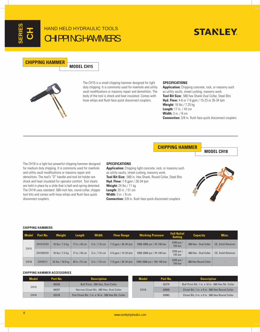
CHIPPING HAMMERMODEL CH15
The CH15 is a small chipping hammer designed for light duty chipping. It is commonly used for manhole and utility vault modifications or masonry repair and demolition. The body of the tool is shock and heat insulated. Comes with hose whips and flush-face quick disconnect couplers.
SPECIFICATIONSApplication: Chipping concrete, rock, or masonry such as utility vaults, street curbing, masonry work.Tool Bit Size: .580 hex Shank Oval Collar, Steel BitsHyd. Flow: 4-6 or 7-9 gpm / 15-23 or 26-34 lpmWeight: 16 lbs / 7.25 kgLength: 17 in. / 43 cmWidth: 3 in. / 8 cmConnection: 3/8 in. flush face quick disconnect couplers
CHIPPING HAMMERMODEL CH18
The CH18 is a light but powerful chipping hammer designed for medium duty chipping. It is commonly used for manhole and utility vault modifications or masonry repair and demolition. The tool’s “D” handle and tool bit holder are shock and heat insulated for operator comfort. Tool steels are held in place by a slide that is ball-and-spring detented. The CH18 uses standard .580-inch hex, round collar, chipper tool bits and comes with hose whips and flush-face quick disconnect couplers.
SPECIFICATIONSApplication: Chipping light concrete, rock, or masonry such as utility vaults, street curbing, masonry work.Tool Bit Size: .580 in. Hex Shank, Round Collar, Steel BitsHyd. Flow: 7-9 gpm / 26-34 lpmWeight: 24 lbs / 11 kgLength: 20 in. / 51 cmWidth: 3 in. / 8 cmConnection: 3/8 in. flush face quick disconnect couplers
Model Part No. Weight Length Width Flow Range Working Pressure Full Relief Setting Capacity Misc.
CH15
CH1513101 16 lbs / 7.3 kg 17 in. / 43 cm 3 in. / 7.6 cm 7-9 gpm / 26-34 lpm 1000-2000 psi / 70-140 bar 2250 psi / 155 bar .580 Hex - Oval Collar CE, Solid Retainer
CH1553101 16 lbs / 7.3 kg 17 in. / 43 cm 3 in. / 7.6 cm 4-6 gpm / 15-23 lpm 1000-2000 psi / 70-140 bar 2250 psi / 155 bar .580 Hex - Oval Collar CE, Solid Retainer
CH18 CH18111 24 lbs / 10.9 kg 20 in. / 51 cm 3 in. / 7.6 cm 7-9 gpm / 26-34 lpm 1500-2000 psi / 105-140 bar 2250 psi / 155 bar .580 Hex-Round Collar -
CHIPPING HAMMERS
CHIPPING HAMMER ACCESSORIES
Model Part No. Description
CH1566256 Bull Point, .580 Hex, Oval Collar
66257 Narrow Chisel Bit, .580 Hex, Oval Collar
CH18 02278 Flat Chisel Bit, 1 in. x 18 in. .580 Hex Rd. Collar
Model Part No. Description
CH18
02279 Bull Point Bit, 1 in. x 18 in. .580 Hex Rd. Collar
03690 Chisel Bit, 1 in. x 9 in. .580 Hex Round Collar
03963 Chisel Bit, 2 in. x 5 in. .580 Hex Round Collar
HAND HELD HYDRAULIC TOOLS
CHIPPING HAMMERS

www.stanleyhydraulics.com www.stanleyhydraulics.com 9
SERIES
DR
&
PD
DIGGERMODEL DR19 SPECIFICATIONS
Application: Digging and rod driving in heavy clay, light shale, hardpan, frozen ground or dry hard dirt.Tool Bit Size: 7/8-in. Hex x 3-1/4 in. Shank Steel BitsHyd. Flow: 7-9 gpm / 26-34 lpmWeight: 24 lbs / 10.9 kgLength: 20 in. / 50.8 cmWidth: 3 in. / 8 cmConnection: 3/8 in. flush-face quick disconnect couplers
The DR19 is a compact digging spade for digging in materials such as heavy clay or light shale. The tool’s “D” handle and tool bit holder are shock and heat insulated for operator comfort. Tool steels are held in place by a slide that is ball-and-spring detented. The DR19 uses standard 7/8-inch hex, round collar, steel tool bits and comes with hose whips and flush-face quick disconnect couplers.
Model Part No. Weight Length Width Flow Range Working PressureFull Relief
SettingBlows/Minute Capacity
DR19 DR19111 24 lbs / 10.9 kg 20 in. / 50 cm 3 in. / 7.6 cm 7-9 gpm / 26-34 lpm 1500-2000 psi / 105-140 bar 2250 psi / 155 bar 1800 bpm 7/8-in. x 3-1/4 in. Shank
DIGGERS
Model Part No. Description
DR19
02328 Clay Spade, 16 in. U/C
02330 3 in. Chisel, 14 in. U/C
02339 1 in. Chisel, 14 in. U/C
Model Part No. Description
DR19
02341 Asphalt Cutter, 5 in. blade x 11 in. U/C
04401 Moil Point, 18 in. U/C
05255 Rod Driver, 3/4 in.
DIGGER ACCESSORIES
POST DRIVERMODEL PD45
SPECIFICATIONSApplication: Drives a variety of shapes and sizes of sign postsCapacity: U-Channel Posts, Square Posts, Round Post, DelineatorsHyd. Flow: 7-9 gpm / 26-34 lpmWeight: 65 lbs / 29 kgLength: 30 in. / 76 cmWidth: 10 in. / 25 cmConnection: 3/8 in. flush face quick disconnect couplers
The PD45 features dual guiding handles, a lifting eye and remote or integral On/Off Valve. Models with integral triggers run the full length of the handles and are spring loaded to the OFF position. A model is available to drive DOT required breakaway posts to within 4 inches / 100 mm above ground level. All PD45 models are furnished with flush faced quick disconnect couplers.
Model Part No. Weight Length Width Flow Range Working Pressure Full Relief Setting Capacity Misc.
PD45
PD45131 65 lbs / 29 kg 30 in. / 76 cm 10 in. / 25 cm 7-9 gpm / 26-34 lpm
1000-2000 psi / 70-140 bar 2250 psi / 155 bar U-Channel, Delineator,
Square & Round Post In-Line Valve
PD45132 67 lbs / 30 kg 30 in. / 76 cm 10 in. / 25 cm 7-9 gpm / 26-34 lpm
1000-2000 psi / 70-140 bar 2250 psi / 155 bar U-Channel, Delineator,
Square & Round PostValve In Handle
PD45132G 67 lbs / 30 kg 30 in. / 76 cm 10 in. / 25 cm 7-9 gpm / 26-34 lpm
1000-2000 psi / 70-140 bar 2250 psi / 155 bar U-Channel, Delineator,
Square & Round PostValve In Handle
Extended Anvil
PD45151 65 lbs / 29 kg 30 in. / 76 cm 10 in. / 25 cm 7-9 gpm / 26-34 lpm
1000-2000 psi / 70-140 bar 2250 psi / 155 bar U-Channel, Delineator,
Square & Round PostNo Valve, Hoses, or Couplers
POST DRIVER
Part No. Description
15184 Adapter - 1-3/4 in. square post
15185 Adapter - 2 in. round post
15186 Adapter - 2-1/4 in. sq. post
Part No. Description
15187 Adapter - 2 in. sq. post
67784 Adapter - 1-3/4 in. round post
POST DRIVER ACCESSORIES
HAND HELD HYDRAULIC TOOLS
DIGGER & POST DRIVER

www.stanleyhydraulics.com www.stanleyhydraulics.com10
HAND HELD HYDRAULIC TOOLS
PULLERS & DRIVERSSER
IES
PP &
SD
POST PULLERMODEL PP10
The PP10 is designed to remove flanged type sign posts and irregularly shaped posts up to 8 in. / 20 cm wide. It features an 8 inch / 203 cm stroke and pulling force of 9800 lbs / 4450 kg. The PP10 uses two methods to solve post pulling problems. For flanged posts, the PP10 uses gripper jaws to grasp the flange. For many other posts, a chain is used. Pins on the end of the chain may be inserted into holes in perforated posts to keep the chain from sliding. A control valve is located on the tool. The PP10 is furnished with gripper jaws, chain with pins, and flush face quick disconnect couplers.
SPECIFICATIONSApplication: Pulls a variety of sign and fence postsCapacity: Sign posts up to 8 in. / 20 cm WideHyd. Flow: 3-9 gpm / 11-34 lpmWeight: 70 lbs / 32 kgLength: 13 in. / 32 cmWidth: 14 in. / 35 cmConnection: 3/8 in. flush face quick disconnect couplers
Model Part No. Weight Length Width Flow Range Working Pressure Full Relief Setting Capacity Misc.
PP10 PP10100 70 lbs / 32 kg 13 in. / 32 cm 14 in. / 35 cm 3-9 gpm / 11-34 lpm 1000-2000 psi / 70-140 bar 2250 psi / 155 bar 8 in. / 20 cm Post -
POST PULLER
Stanley’s SD67 Spike Driver is rugged and lightweight for use in medium to heavy-duty driving applications. The anti-vibration handles help reduce operator fatigue. Comes in two length options.
SPECIFICATIONSApplication: Securing temporary plates in the road during constructionWeight: 70 lbs / 31.8 kgLength: 28.75 or 32.25 in. / 73 or 82 cmWidth at Handles: 18 in. / 45.8 cmWorking Pressure: 1000-2000 psi / 70-140 barFlow Range: 5-10 gpm / 20-38 lpmMax. Back Pressure: 250 psi / 17 barCup Width: 2.9 in. / 7.4 cm
Cup Inside Diameter: 1.9 in. / 4.8 cmPorting: 8 SAE O-ringConnection: HTMA flush faced coupler
FEATURES• Rugged, lightweight construction for use in medium
duty spike driving reduces operator fatigue• Anti-vibration handle isolates the tool’s vibration,
further reducing operator fatigue• Two length options are available which allow operator
to stand in a fully-upright position for better comfort• Feathering On/Off valve allows the operator to control
the output energy of the tool, providing more control and ease of handling
• Diaphragm-type accumulator design provides for ease of maintenance and extended service life of the tool
SPIKE DRIVERMODEL SD67
SPIKE DRIVERS
Model Part No. Weight Length Width Flow Range Working Pressure Full Relief Setting Capacity Misc.
SD67SD67101 70 lbs / 31.8 kg 28.75 in. / 73 cm 18 in. / 45.8 cm 5-10 gpm / 20-38 lpm 1000-2000 psi / 70-140 bar 2250 psi / 155 bar 1.9 in. / 4.8 cm spikes -
SD67141 70 lbs / 31.8 kg 32.25 in. / 82 cm 18 in. / 45.8 cm 5-10 gpm / 20-38 lpm 1000-2000 psi / 70-140 bar 2250 psi / 155 bar 1.9 in. / 4.8 cm spikes -

www.stanleyhydraulics.com www.stanleyhydraulics.com 11
HAND HELD HYDRAULIC TOOLS
PULLERS & TAMPERS
SERIES
SP &
TA
SPIKE PULLERMODEL SPL31
Stanley’s SPL31 Lightweight Spike Puller provides the ultimate in spike removal. The dual-stage trigger greatly reduces spike kick-back to the operator. Pulling of spikes can be accomplished from any position making spike pulling simple and effortless.
SPECIFICATIONSApplication: Removing spikes used to secure temporary plates in the road during constructionWeight: 31 lbs* / 14 kgLength: 32.75 in. / 83 cmWidth at Handles: 16.25 in. / 46 cm
Working Pressure: 2000-2500 psi / 70-140 barFlow Range: 5-10 gpm / 18-38 lpmMax. Back Pressure: 250 psi / 17 barPulling Force: 16,647 lbs / 7551 kgConnection: 3/8 in. flush faced quick disconnect couplers
FEATURES• Removes hairpin or cut spikes• Pulls bent or damaged spikes• Ergonomically designed trigger
SPIKE PULLER
Model Part No. Description Weight Length Handle Width Flow Range Working Pressure Pulling Force
SPL31 SPL31A Automatic Cycle 31 lbs* / 14 kg 32.75 in. / 83 cm 16.25 in. / 40.6 cm 5-10 gpm / 18-38 lpm 2000-2500 psi / 70-140 bar 16,647 lbs / 7551 kg
*31 lb tool weight is wet without whips and couplers
TAMPERMODEL TA54
SPECIFICATIONSApplication: Compacting soil around utility poles, sign and fence posts - backfill compaction.Capacity: Kidney shaped or 6 inch round shoeHyd. Flow: 3-9 gpm / 11-34 lpmWeight: 39 lbs / 18 kgLength: 71 in. / 180 cmWidth: 4 in. / 10 cmConnection: -8 SAE Port
FEATURES• Ideal for soil compaction around utility poles,
signs, fence posts and backfill.• Long stroke keeps the TA54 above the fill• 1600 blows per minute - 2-1/2 inch stroke • On/Off valve in handle or in-line valve• 2 moving parts
TA54103 with valve in handle
TAMPER SPECIFICATIONS AND ACCESSORIES ON THE FOLLOWING PAGE //

www.stanleyhydraulics.com www.stanleyhydraulics.com12
HAND HELD HYDRAULIC TOOLS
TAMPERS & EARTH AUGERSSER
IES
TA &
EA
Model Part No. Weight Length Width Flow Range Working PressureFull Relief
SettingBlows/Minute Valve Shoe Coupler
TA54
TA54103 30 lbs / 13.6 kg 71 in. / 180 cm 4 in. / 10 cm 3-9 gpm / 11-34 lpm 1000-2000 psi / 70-140 bar 2250 psi / 155 bar 1600 bpm In-handle Kidney Yes
TA54603 30 lbs / 13.6 kg 71 in. / 180 cm 4 in. / 10 cm 3-9 gpm / 11-34 lpm 1000-2000 psi / 70-140 bar 2250 psi / 155 bar 1600 bpm No Valve Kidney No
TA54603A 37 lbs / 17 kg 71 in. / 180 cm 4 in. / 10 cm 3-9 gpm / 11-34 lpm 1000-2000 psi / 70-140 bar 2250 psi / 155 bar 1600 bpm Remote In-line Kidney Yes
TA54113 30 lbs / 13.6 kg 71 in. / 180 cm 4 in. / 10 cm 3-9 gpm / 11-34 lpm 1000-2000 psi / 70-140 bar 2250 psi / 155 bar 1600 bpm In-handle 6 in. Round Shoe Yes
TAMPERS
Model Part No. Description
TA54
01230 10 ft. Siamese Hose
00833 Kidney Shoe
00836 8 ft. Siamese Hose
00840 Round Shoe, 6 in. dia.
Model Part No. Description
TA5401070 Rectangular Shoe
72264 In-Line Valve Assembly, OC/CC
TAMPER ACCESSORIES
EARTH AUGERMODEL EA08
The EA08 features an output torque of 250 ft lb / 339 Nm to handle a wide variety of earth boring applications up to 18 inches / 46 cm in diameter and 42 inches / 107 cm deep. It is configured with 4 handles for two-man operation but can be used by one-man by connecting the torque tube to a power unit or other solid object. An ergonomically designed forward and reverse control valve lever is integrated into the handle. The EA08 accepts 1-3/8 in. hex female augers. The EA08 is furnished with flush face quick disconnect couplers. Augers are sold separately.
SPECIFICATIONSApplication: Earth boring for posts and poles.Capacity: Up to 18 in. / 46 cm Diameter x 42 in. / 107 cm Long AugerHyd. Flow: 7-9 gpm / 26-34 lpmWeight: 47 lbs / 21 kgLength: 11 in. / 30 cmWidth: 46 in. / 117 cmConnection: 3/8 in. flush face quick disconnect couplers
Model Part No. Weight Length Width Flow Range Working Pressure Full Relief Setting Capacity Misc.
EA08 EA08102A 47 lbs / 21 kg 11 in. / 30 cm 46 in. / 117 cm 7-9 gpm / 26-34 lpm 1000-2000 psi / 70-140 bar 2250 psi / 155 bar 18 in. / 46 cm Dia. Auger 1-3/8 in. Hex Male
EARTH AUGER
Part No. Description
47406 Auger, 2 in. dia x 42 in. OAL (requires 58585)
47407 Auger, 3 in. dia x 42 in. OAL (requires 58586)
47408 Auger, 4 in. dia x 42 in. OAL
47409 Auger, 6 in. dia x 42 in. OAL
47410 Auger, 8 in. dia x 42 in. OAL
47411 Auger, 10 in. dia x 42 in. OAL
47412 Auger, 12 in. dia x 42 in. OAL
47413 Auger, 16 in. dia x 42 in. OAL
47414 Auger, 18 in. dia Nursery
Part No. Description
47415 Extension Tube, 15 in. OAL
47429 Digging Tooth w/Hardface
47430 2 in. Center Screw Bit for 6-12 in.
47431 Center Screw Bit for 3 in.
47432 Center Screw Bit for 4 in.
39408 Coupler, 1-1/4 in. Square Female
58585 Drive Coupler, 13/16 x 1-3/8 in. for 47406 Auger
58586 Drive Coupler, 1-1/8 x 1-1/8 in. for 47407 Auger
39410 Auger Extension, 8 in. dia. x 36 in. OAL
65477 Drive Hub, Stanley 1-1/4 in. Hex
EARTH AUGER ACCESSORIES
www.stanleyhydraulics.com www.stanleyhydraulics.com 13
HAND HELD HYDRAULIC TOOLS
CUT-OFF SAWS
SERIES
CO
Model Part No. Weight Length Width Flow Range Working PressureFull Relief
SettingBlows/Minute Valve Shoe Coupler
TA54
TA54103 30 lbs / 13.6 kg 71 in. / 180 cm 4 in. / 10 cm 3-9 gpm / 11-34 lpm 1000-2000 psi / 70-140 bar 2250 psi / 155 bar 1600 bpm In-handle Kidney Yes
TA54603 30 lbs / 13.6 kg 71 in. / 180 cm 4 in. / 10 cm 3-9 gpm / 11-34 lpm 1000-2000 psi / 70-140 bar 2250 psi / 155 bar 1600 bpm No Valve Kidney No
TA54603A 37 lbs / 17 kg 71 in. / 180 cm 4 in. / 10 cm 3-9 gpm / 11-34 lpm 1000-2000 psi / 70-140 bar 2250 psi / 155 bar 1600 bpm Remote In-line Kidney Yes
TA54113 30 lbs / 13.6 kg 71 in. / 180 cm 4 in. / 10 cm 3-9 gpm / 11-34 lpm 1000-2000 psi / 70-140 bar 2250 psi / 155 bar 1600 bpm In-handle 6 in. Round Shoe Yes
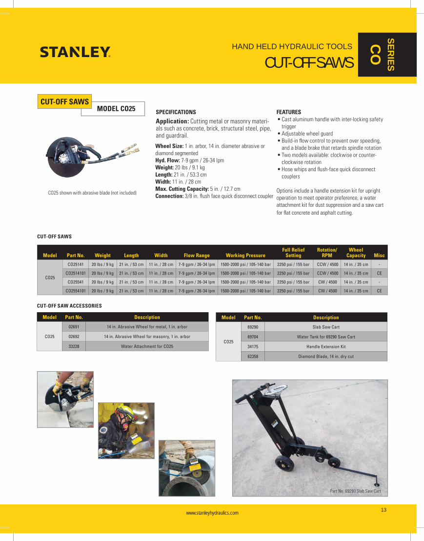
CUT-OFF SAWSMODEL CO25
CO25 shown with abrasive blade (not included)
SPECIFICATIONS FEATURES• Cast aluminum handle with inter-locking safety
trigger• Adjustable wheel guard• Build-in flow control to prevent over speeding,
and a blade brake that retards spindle rotation• Two models available: clockwise or counter-
clockwise rotation• Hose whips and flush-face quick disconnect
couplers
Options include a handle extension kit for upright operation to meet operator preference, a water attachment kit for dust suppression and a saw cart for flat concrete and asphalt cutting.
Application: Cutting metal or masonry materi-als such as concrete, brick, structural steel, pipe, and guardrail.
Wheel Size: 1 in. arbor, 14 in. diameter abrasive or diamond segmentedHyd. Flow: 7-9 gpm / 26-34 lpmWeight: 20 lbs / 9.1 kgLength: 21 in. / 53.3 cmWidth: 11 in. / 28 cmMax. Cutting Capacity: 5 in. / 12.7 cmConnection: 3/8 in. flush face quick disconnect coupler
Model Part No. Weight Length Width Flow Range Working PressureFull Relief
SettingRotation/
RPMWheel
Capacity Misc
CO25
CO25141 20 lbs / 9 kg 21 in. / 53 cm 11 in. / 28 cm 7-9 gpm / 26-34 lpm 1500-2000 psi / 105-140 bar 2250 psi / 155 bar CCW / 4500 14 in. / 35 cm -
CO2514101 20 lbs / 9 kg 21 in. / 53 cm 11 in. / 28 cm 7-9 gpm / 26-34 lpm 1500-2000 psi / 105-140 bar 2250 psi / 155 bar CCW / 4500 14 in. / 35 cm CE
CO25541 20 lbs / 9 kg 21 in. / 53 cm 11 in. / 28 cm 7-9 gpm / 26-34 lpm 1500-2000 psi / 105-140 bar 2250 psi / 155 bar CW / 4500 14 in. / 35 cm -
CO2554101 20 lbs / 9 kg 21 in. / 53 cm 11 in. / 28 cm 7-9 gpm / 26-34 lpm 1500-2000 psi / 105-140 bar 2250 psi / 155 bar CW / 4500 14 in. / 35 cm CE
CUT-OFF SAWS
Model Part No. Description
CO25
02691 14 in. Abrasive Wheel for metal, 1 in. arbor
02692 14 in. Abrasive Wheel for masonry, 1 in. arbor
33228 Water Attachment for CO25
Model Part No. Description
CO25
69290 Slab Saw Cart
69704 Water Tank for 69290 Saw Cart
34175 Handle Extension Kit
62358 Diamond Blade, 14 in. dry cut
CUT-OFF SAW ACCESSORIES
Part No. 69290 Slab Saw Cart

www.stanleyhydraulics.com www.stanleyhydraulics.com14
SER
IES
CS HAND HELD HYDRAULIC TOOLS
WOOD CUTTING CHAINSAWS
MAXIMUM CUTTING POWER
CUTTING WITH HYDRAULIC POWEROperators familiar with conventional cutting equipment such as gasoline chain saws and circle saws are easily impressed with the power of hydraulic cutting equipment because the power-to-weight ratio is significantly higher. For example, our CS06 Chainsaw produces almost twice as much power as its gasoline engine counterparts and weighs about half as much.
Compared to conventional cutting equipment Stanley hydraulic cutting tools offer:• More work in less time• Less effort• Longer tool life• Minimal maintenance• Minimal downtime• Increased safety• Longer warranty
CHAIN SAWMODEL CS05/CS06
FEATURES• Highest power-to-weight ratio of any chain saw
on the market today• Trigger Lock • Hand guard• Dual spool for open center or closed center
operation• Low kickback bars and chains• Inherently low-kickback hydraulic motor• Automatic chain oiler• Hyrevz™ motor
SPECIFICATIONSApplication: Wood Cutting - Trees, Limbs, Timbers, Utility Poles, Wood StructuresCapacity: 12, 15, & 20 in. / 30, 38, & 51 cm BarsHyd. Flow: 4-6 gpm / 15-23 lpm for CS05, 7-9 gpm / 26-34 lpm for CS06Weight: 6.25 lbs / 2.8 kgOverall Length: 27, 30, & 35 in. / 69, 76, & 89 cmWidth: 9 in. / 23 cmConnection: 3/8 in. NPT Male Adapter (couplers sold separately)
CS06

www.stanleyhydraulics.com www.stanleyhydraulics.com 15
HAND HELD HYDRAULIC TOOLS
WOOD CUTTING CHAINSAWS
SERIES
CS
CHAIN SAWMODEL CS25/CS28
SPECIFICATIONSApplication: Tree TrimmingCapacity: 12 in. / 30 cm BarsHyd. Flow: 4-6 gpm / 15-23 lpm for CS25, 7-9 gpm / 26-34 lpm for CS28Weight: 8.4 & 9 lbs / 3.8 & 4 kgOverall Length: 75 & 90 in. / 191 & 229 cmWidth: 4.375 in. / 11 cmConnection: 3/8 in. NPT Male Adapter (couplers sold separately)
FEATURES• Used for trimming and pruning large
tree branches• Ideal for use by right-of-way crews,
arborists, utilities, parks departments, grounds keepers, and forest trail maintenance crews
• Fiberglass pole handle• Hyrevz™ motor
• Dual spool for operation on open center or closed center systems
• Automatic chain oiling
¹ Measured at motor end
Model Part No. Weight Overall Length Width Flow RangeWorking Pressure
Full Relief Setting Cut Capacity Misc.
CS05CS05610 6.25 lbs / 2.8 kg 27 in. / 69 cm 9 in. / 23 cm 4-6 gpm / 15-23 lpm 1500-2000 psi /
105-140 bar 2250 psi / 155 bar 13 in. / 33 cm OC/CC
CS05620 6.25 lbs / 2.8 kg 30 in. / 76 cm 9 in. / 23 cm 4-6 gpm / 15-23 lpm 1500-2000 psi / 105-140 bar 2250 psi / 155 bar 15 in. / 38 cm OC/CC
CS06
CS06610 6.25 lbs / 2.8 kg 27 in. / 69 cm 9 in. / 23 cm 7-9 gpm / 26-34 lpm 1500-2000 psi / 105-140 bar 2250 psi / 155 bar 13 in. / 33 cm OC/CC
CS06620 6.25 lbs / 2.8 kg 30 in. / 76 cm 9 in. / 23 cm 7-9 gpm / 26-34 lpm 1500-2000 psi / 105-140 bar 2250 psi / 155 bar 15 in. / 38 cm OC/CC
CS06630 6.25 lbs / 2.8 kg 35 in. / 89 cm 9 in. / 23 cm 7-9 gpm / 26-34 lpm 1500-2000 psi / 105-140 bar 2250 psi / 155 bar 20 in. / 51 cm OC/CC
CS25CS25811 9 lbs / 4 kg 90 in. / 229 cm 4.375 in. / 11 cm ¹ 4-6 gpm / 15-23 lpm 1000-2000 psi
/ 70-140 bar 2250 psi / 155 bar 12 in. / 30 cm OC/CC
CS25812 9 lbs / 4 kg 75 in. / 191 cm 4.375 in. / 11 cm ¹ 4-6 gpm / 15-23 lpm 1000-2000 psi / 70-140 bar 2250 psi / 155 bar 12 in. / 30 cm OC/CC
CS28CS28811 9 lbs / 4 kg 90 in. / 229 cm 4.375 in. / 11 cm ¹ 7-9 gpm / 26-34 lpm 1000-2000 psi
/ 70-140 bar 2250 psi / 155 bar 12 in. / 30 cm OC/CC
CS28812 8.4 lbs / 3.8 kg 75 in. / 191 cm 4.375 in. / 11 cm ¹ 7-9 gpm / 26-34 lpm 1000-2000 psi / 70-140 bar 2250 psi / 155 bar 12 in. / 30 cm OC/CC
CHAIN SAWS
Model Part No. Description
CS05/CS06
07629 Rim Sprocket, .325P x 7 tooth
07638 15 in. Saw Bar
07639 20 in. Saw Bar
07641 Saw Chain for 15 in. bar
07642 Saw Chain for 20 in. bar
CS25/CS28
05144 Chain/Bar Guard
07616 Sprocket Spline Adapter
07629 Rim Sprocket, .325P x 7 tooth
Model Part No. Description
ALL
12363 File Guide
08347 13 in. Saw Bar
08348 Saw Chain for 13 in. bar
11464 Scrench
33289 Chain Saw File
11294 Flat File
CHAIN SAW ACCESSORIES

www.stanleyhydraulics.com www.stanleyhydraulics.com16
HAND HELD HYDRAULIC TOOLS
CONCRETE CUTTING CHAINSAWSSER
IES
DS
THE BEST YOU EVER SAW
Model DS06
DS06 & DS11 DIAMOND CHAIN SAWSDiamond chain saws use a revolutionary chain with laser welded segments impregnated with diamonds. This chain, coupled with a bar containing water channels for chain lubrication, make cutting concrete, brick, masonry, and stone an easy task.
A distinct advantage of a diamond chain saw over a diamond circular saw is cutting square corners without over-cut. A diamond chain saw is the perfect tool for plunge cutting for window and door openings, air conditioner cut-outs, and notching or trimming.
DIAMOND CHAIN TECHNOLOGYThe newest generation of diamond chains dramatically reduce the chain wear of cutting concrete. SealPro™ technology extends chain chassis life by up to 50% or more, simplifies water pressure requirements and reduces the frequency of chain tensioning adjustments.
SealPro™ technology incorporates a patented new chain chassis design that seals out abrasive contaminants. A unique 0-ring design seals the rivet-joints of the chain, keeping the abrasive materials out and the lubrication in.
Diamond chains with SealPro™ work at low water pressures eliminating the need for water booster pumps. The new chains can be used with water from an ordinary garden hose and will yield excellent chain life at pressures as low as 20 psi.
Other important advantages of SealPro™ technology are reduced chain stretch resulting in fewer tensioning adjustments over time.
CHAIN SELECTION CHART
Aggregate Extra Hard Hard Medium Soft Abrasive
Material Chert Flint Basalt Quartz
Granite River Rock
Marble Limestone Sandstone Masonry, Brick, Block,
Green Concrete
Approximate Moh’s Scale 9 8 7 6 5 4 3
Reinforcing SteelLots of Steel Some Steel No Steel
1" Double Mat Single Mat #5 #4 #3 Wire Mesh
Saw Chain Wear (in.-ft.) Pinnacle-32 Pinnacle-37
150 in-ft 600-800 in-ft 2000 in-ft
Ultra-32 Ultra-37 200 in-ft 1500 in-ft

www.stanleyhydraulics.com www.stanleyhydraulics.com 17
HAND HELD HYDRAULIC TOOLS
CONCRETE CUTTING CHAINSAWS
SERIES
DS
DIAMOND CHAIN SAWMODEL DS06
The DS06 is lightweight, powerful and ideal for fast cutting of concrete, reinforced concrete, conduit, brick, stone and other masonry. 13 inch plunge cut capability allows quick cutting of window, door, conduit and duct openings in walls and notching and trimming of concrete pipe. Trigger activated water for lubrication and cooling is ported through the bar and applied at the point where the concrete is being cut.
The DS06 is provided with The Wall Walker™ to provide leverage for cutting, water connection, and flush face quick disconnect couplers. The bar and chain are sold separately.
SPECIFICATIONSApplication: Cutting concrete, reinforced concrete, conduit, brick, stone and other masonry.Capacity: 13 in. / 33 cm BarHyd. Flow: 4-6 or 7-9 gpm / 15-23 or 26-34 lpm (see ordering info)Weight: 14 lbs / 6 kgLength: 24 in. / 61 cmWidth: 9 in. / 23 cmConnection: 3/8 in. flush face quick disconnect couplers
DIAMOND CHAIN SAWMODEL DS11
The DS11 is a heavy duty and powerful diamond chain saw that is ideal for fast cutting of concrete, reinforced concrete, conduit, brick, stone and other masonry. Plunge cut capability allows quick cutting of window, door, conduit and duct openings in walls and notching and trimming of concrete pipe. Trigger activated water for lubrication and cooling is ported through the bar and applied at the point where the concrete is being cut.
The DS11 features ergonomic handles and guards to help reduce operator fatigue, water connection, flush face quick disconnect couplers, and is powered by a Stanley
Hyrevz™ motor. The Wall Walker™ that provides leverage for cutting is standard equipment. The bar and chain are sold separately.
SPECIFICATIONSApplication: Cutting concrete, reinforced concrete, conduit, brick, stone and other masonry.Capacity: 15 or 18 in. / 33 or 46 cm Bar Hyd. Flow: 7-9 gpm / 26-34 lpmWeight: 26 lbs / 11 kgLength: 38 in. / 97 cmWidth: 9 in. / 23 cmConnection: 3/8 in. flush face quick disconnect couplers
Model Part No. Weight Length Width Flow Range Working Pressure Full Relief Setting Output Discharge
DS06
DS06200001* 14 lbs / 6 kg 24 in. / 61 cm 9 in. / 23 cm 4-6 gpm / 15-23 lpm 1000-2000 psi / 70-140 bar 2250 psi / 155 bar 13 in. / 33 cm Bar CE
DS063000* 14 lbs / 6 kg 24 in. / 61 cm 9 in. / 23 cm 7-9 gpm / 26-34 lpm 1000-2000 psi / 70-140 bar 2250 psi / 155 bar 13 in. / 33 cm Bar -
DS06300001* 14 lbs / 6 kg 24 in. / 61 cm 9 in. / 23 cm 7-9 gpm / 26-34 lpm 1000-2000 psi / 70-140 bar 2250 psi / 155 bar 13 in. / 33 cm Bar CE
DS11 DS113000* 26 lbs / 11 kg 38 in. / 97 cm 9 in. / 23 cm 7-9 gpm / 26-34 lpm 1000-2000 psi / 70-140 bar 2250 psi / 155 bar 15, 18 in. / 33, 46 cm Bar CE
DIAMOND SAWS
* NOTE: Bar and Chain Not Included - Must be Ordered Separately
Model Part No. Description
DS06
35037 Bar, 13 in. Sprocket Nose
56799 Diamond Chain, 13 in. Ultra 25
56800 Diamond Chain, 13 in. Pinnacle 25
65797 Flap Kit
DS06/DS11
20857 Chain Repair Spinner
20858 Chain Repair Breaker
20859 Diamond Chain Butterfly Repair Kit
60859 Water Flow Meter, 0-7 gpm
56767 Connecting Link, 5-Pack
Model Part No. Description
DS11
30305 Bar, 15 in., sprocket nose
30306 Bar, 18 in., sprocket nose
56801 Diamond Chain, 15 in., Ultra 32
56802 Diamond Chain, 18 in., Ultra 37
56803 Diamond Chain, 15 in., Pinnacle 32
58632 Diamond Chain, 18 in., Pinnacle 37
23517 Sprocket Wrench
DIAMOND SAW ACCESSORIES
www.stanleyhydraulics.com www.stanleyhydraulics.com18
HAND HELD HYDRAULIC TOOLS
DUCTILE IRON PIPE CHAINSAW & PUMPSER
IES
DS
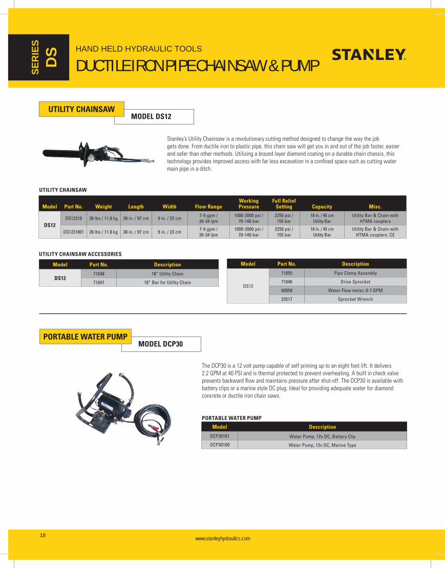
Stanley’s Utility Chainsaw is a revolutionary cutting method designed to change the way the job gets done. From ductile iron to plastic pipe, this chain saw will get you in and out of the job faster, easier and safer than other methods. Utilizing a brazed layer diamond coating on a durable chain chassis, this technology provides improved access with far less excavation in a confined space such as cutting water main pipe in a ditch.
UTILITY CHAINSAWMODEL DS12
Model Part No. Weight Length Width Flow RangeWorking Pressure
Full Relief Setting Capacity Misc.
DS12DS12318 26 lbs / 11.8 kg 38 in. / 97 cm 9 in. / 23 cm 7-9 gpm /
26-34 lpm1000-2000 psi /
70-140 bar2250 psi / 155 bar
18 in. / 45 cm Utility Bar
Utility Bar & Chain with HTMA couplers
DS1231801 26 lbs / 11.8 kg 38 in. / 97 cm 9 in. / 23 cm 7-9 gpm / 26-34 lpm
1000-2000 psi / 70-140 bar
2250 psi / 155 bar
18 in. / 45 cm Utility Bar
Utility Bar & Chain with HTMA couplers. CE
UTILITY CHAINSAW
UTILITY CHAINSAW ACCESSORIES
Model Part No. Description
DS1271048 18” Utility Chain
71047 18” Bar for Utility Chain
Model Part No. Description
DS12
71055 Pipe Clamp Assembly
71046 Drive Sprocket
60859 Water Flow meter, 0-7 GPM
23517 Sprocket Wrench
PORTABLE WATER PUMPMODEL DCP30
The DCP30 is a 12 volt pump capable of self priming up to an eight foot lift. It delivers 2.2 GPM at 40 PSI and is thermal protected to prevent overheating. A built in check valve prevents backward flow and maintains pressure after shut-off. The DCP30 is available with battery clips or a marine style DC plug. Ideal for providing adequate water for diamond concrete or ductile iron chain saws.
PORTABLE WATER PUMP
Model Description
DCP30101 Water Pump, 12v DC, Battery Clip
DCP30100 Water Pump, 12v DC, Marine Type

www.stanleyhydraulics.com www.stanleyhydraulics.com 19
HAND HELD HYDRAULIC TOOLS
CIRCULAR SAW & PRUNERS
SERIES
CR
&
PR
CIRCULAR SAWMODEL CR27
SPECIFICATIONSApplication: Tree Trimming and Brush CuttingCapacity: 9 in. / 23 cm Dia. Saw BladeHyd. Flow: 5-7 gpm / 19-26 lpmWeight: 9.75 lbs / 4.4 kgLength: 79 in. / 200 cmWidth: 9 in. / 23 cmConnection: 3/8 in. NPT Male Adapter (couplers sold separately)
FEATURES• Used for trimming and pruning tree branches• Ideal for use by right-of-way crews, arborists,
utilities, parks departments, grounds keepers, and forest trail maintenance crews
• Fiberglass pole handle• Integral Hyrevz™ motor• Angled head
• Dual spool for operation on Open Center or Closed Center systems
• Double cone-lock blade nut• Blade brake to reduce coast-down time• Comes with 9" blade (34356)
Model Part No. Weight Length Flow RangeWorking Pressure
Full Relief Setting Cutting Component (included) Couplers
CR27 CR27891 9.6 lbs / 4.4 kg 79 in. / 200.7 cm 5-7 gpm / 19-26 lpm 1000-2000 psi / 70-140 bar
2250 psi / 155 bar 9 in. / 22.9 cm Saw Blade - 24 Tooth No
CIRCLE SAWS
CIRCLE SAW ACCESSORIES
Part No. Description
34356 9 in. / 22.9 cm Circle Saw Blade - 24 Tooth
00425 9 in. / 22.9 cm Circle Saw Blade - 44 Tooth
Part No. Description
34653 Tooth Setting Tool for 34356 Blade
11299 File Guide with 7/32 in. round File
PRUNERMODEL PR41
SPECIFICATIONSApplication: Tree TrimmingCapacity: 2.25 in. / 5.7 cm CutHyd. Flow: 3-9 gpm / 11-34 lpmWeight: 11.5 lbs / 5.2 kgLength: 84 in. / 213 cmWidth: 6 in. / 15 cmConnection: 3/8 in. NPT Male Adapter (couplers sold separately)
FEATURES• Used for selective tree limb pruning up
a 2-1/4 inch / 5.7 cm cut• Ideal for use by right-of-way crews, arborists,
utilities, parks departments, grounds keepers, and forest trail maintenance crews
• Lightweight head design that provides easy handling
• Full power on both opening and closing cycles• Improved geometry of knife and hook provides
increased cutting efficiency• Fiberglass pole handle• Sold in either open center or closed center
configurations
PRUNER ACCESSORIES
Model Part No. Description
PR41 56849 Knife
Model Part No. Configuration Weight Length Flow RangeWorking Pressure
Full Relief Setting
Cutting Component (included) Couplers
PR41PR41131 Open Center 11.5 lbs / 5.2 kg 84 in. / 213.4 cm 3-9 gpm /
11-34 lpm1000-2000 psi /
70-140 bar 2250 psi / 155 bar 2-1/4 in. / 5.7 cm Cut Knife No
PR41231 Closed Center 11.5 lbs / 5.2 kg 84 in. / 213.4 cm 3-9 gpm / 11-34 lpm
1000-2000 psi / 70-140 bar 2250 psi / 155 bar 2-1/4 in. /
5.7 cm Cut Knife No
PRUNERS

www.stanleyhydraulics.com www.stanleyhydraulics.com20
HAND HELD HYDRAULIC TOOLS
GRINDERSSER
IES
GR
& HG
The GR30 can be used for grinding and cleaning with either cup or standard type grinding wheels and wire or nylon brushes. The GR30 features an assist handle, adjustable, rotating wheel guard, insulated handle, flow control for over-speed prevention, counter-clockwise rotation and is powered by an integral Stanley Hyrevz™ motor. The GR30 is furnished with hose whips and flush face quick disconnect couplers.
SPECIFICATIONSApplication: Grinding and cleaning.Capacity: 5/8 in. - 11 Arbor, 9 in. / 22.8 cm Dia. WheelHyd. Flow: 7-9 gpm / 26-34 lpmWeight: 13 lbs / 5.9 kgLength: 8 in. / 20 cmWidth: 28 in. / 71 cmConnection: 3/8 in. flush face quick disconnect couplers
GRINDERMODEL GR30
BULL-NOSE GRINDERMODEL HG60
The HG60 is ideal for grinding and de-burring drilled holes. Its compact and lightweight design helps reduce operator fatigue in repetitive grinding operations. The built-in flow control valve prevents the chance of excessive spindle speed, protecting the motor and increasing tool life. The HG60 features an interlocking safety trigger, insulated handle, counter-clockwise rotation and is powered by an integral Stanley Hyrevz™ motor. It is furnished with hose whips and flush face quick disconnect couplers.
SPECIFICATIONSApplication: Grinding and de-burring.Capacity: 5/8 in. - 11 Arbor, 2.5 in. Dia. x 2.75 in. Grinding StoneHyd. Flow: 5-10 gpm / 19.38 lpmWeight: 11 lbs / 5.13 kgLength: 23 in. / 58 cmWidth: 3 in. / 8 cmConnection: 3/8 in. flush face quick disconnect couplers
HORIZONTAL GRINDERMODEL HG80
The HG80 is used for grinding and shaping right angle surfaces such as I-beams and structural steel. The HG80 is built for heavy-duty use with deep row ball bearing, needle main spindle bearings, independently supported spindle, and cast aluminum wheel guard. The HG80 features an interlocking safety trigger, insulated handle, spindle shaft lock, counter-clockwise rotation and is powered by an integral Stanley Hyrevz™ motor. It is furnished with hose whips and flush face quick disconnect couplers.
SPECIFICATIONSApplication: Grinding and deburring of right angle surfaces.Capacity: 5/8 in. - 11 Arbor, 8 in. Dia. x 1 in. / 20 x 2.5 cm Grinding Wheel Hyd. Flow: 8-10 gpm / 30-38 lpm Weight: 14 lbs / 6.4 kgLength: 23 in. / 58 cmWidth: 10 in. / 25 cmConnection: 3/8 in. flush-face quick disconnect couplers
Model Part No. Weight Length Width Flow Range Working PressureFull Relief
SettingRotation/
RPMWheel
Capacity Misc.
GR30GR30701 13 lbs / 5.9 kg 8 in. / 20 cm 28 in. / 71 cm 7-9 gpm / 26-34 lpm 1500-2000 psi / 70-140 bar 2250 psi / 155 bar CCW / 5800 9 in. / 22.8 cm -
GR3070101 13 lbs / 5.9 kg 8 in. / 20 cm 28 in. / 71 cm 7-9 gpm / 26-34 lpm 1500-2000 psi / 70-140 bar 2250 pis / 155 bar CCW / 5800 9 in. / 22.8 cm CE
HG60 HG60130B 11 lbs / 5 kg 23 in. / 58 cm 3 in. / 8 cm 5-10 gpm / 19-38 lpm 1500-2000 psi / 70-140 bar 2250 psi / 155 bar CCW / 4500 2-1/2 in. / 6.3 cm Bullnose
HG80HG80110B 14 lbs / 6 kg 23 in. / 58 cm 10 in. / 25 cm 8-10 gpm / 30-38 lpm 1500-2000 psi / 70-140 bar 2250 psi / 155 bar CCW / 4500 8 in. / 20 cm -
HG80120B 14 lbs / 6 kg 23 in. / 58 cm 10 in. / 25 cm 8-10 gpm / 30-38 lpm 1500-2000 psi / 70-140 bar 2250 psi / 155 bar CW / 4500 8 in. / 20 cm -
GRINDERS
Model Part No. Description
GR30
02587 Grinding Wheel for metal, 9 in. dia. x 5/8 in., 11 thd. Arbor
02588 Grinding Wheel for masonry, 9 in. dia. x 5/8 in., 11 thd. Arbor
03691 Grinding Wheel, 7 in. dia. x 5/8 in., 11 thd. Arbor
05194 Depressed Center Wheel Adapter
Model Part No. Description
HG60 30872 Grinding Cone
HG80 26847 Straight Assist Handle
GRINDER ACCESSORIES

www.stanleyhydraulics.com www.stanleyhydraulics.com 21
HAND HELD HYDRAULIC TOOLS
IMPACT DRILLS & WRENCHES
SERIES
ID &
IW
WORLDWIDE IMPACTWe provide tools to municipalities, water districts, governments and private contractors for construction and maintenance of electric power, telephone service, gas, water, wastewater, and cable TV distribution. And to transportation entities for construction and maintenance of streets, roads, highways and railways.
Utility trucks with hydraulic tool circuits or compact power units meeting HTMA standards can operate tools for breaking, drilling and cutting of pavement, railroad cutting and drilling, and many other day-to-day tasks performed by utility workers, road crews, and railway crews.
Our tools are used in cities and towns around the world to help build and maintain their infrastructures.
IW24 and Hydrant Saver tool removing fire hydrant valve seat

www.stanleyhydraulics.com www.stanleyhydraulics.com22
HAND HELD HYDRAULIC TOOLS
IMPACT WRENCHES & DRILLSSER
IES
ID &
D
L
IMPACT DRILL/WRENCHMODEL ID07
The ID07 is a high torque impact wrench used for tightening and loosening nuts and driving lag bolts. Delivers impact torque of up to 500 ft. lbs. / 675 Nm. Available with friction ring or pin type socket retainer.
SPECIFICATIONSApplication: Nut and bolt tightening or loosening.Capacity: 1/2 in. Square Drive or 7/16 in. HexHyd. Flow: 4-12 gpm / 15-45 lpmWeight: 7.2 lbs / 3.3 kgLength: 9 in. / 23 cmWidth: 5 in. / 11 cmConnection: 3/8 in. flush face quick disconnect couplers (Couplers sold separately)
FEATURES• 500 ft. lbs. / 675 Nm of impact torque• Durable Swing-hammer mechanism
• Forward-Reverse spool with heavy duty wiper seals and replaceable seal carriers
• Reverse-flow check valve prevents operation if the tool is plumbed backwards
• Cast-in lifting eye• Built-in selector for Open Center or Closed
Center systems• Replaceable pressure relief valve designed
for serviceability• With or without a trigger guard
DRILLMODEL DL07
The DL07 is a variable speed drill with reverse capability. It features a 1/2 inch keyed chuck, dual position assist handle, dual-spool for open center or closed center operation, trigger guard, and is powered by an integral Hyrevz™ motor. A reverse-flow check valve prevents operation if tool is plumbed backwards. The DL07 is furnished with flush face quick disconnect couplers.
SPECIFICATIONSApplication: Drilling holes in wood, metal, masonry and fiberglass.Capacity: 1/2 in. ChuckRPM: 350-1250 Hyd. Flow: 3-10 gpm / 11-38 lpmWeight: 6 lbs / 2.7 kgLength: 9 in. / 23 cmWidth: 4 in. / 10 cmConnection: 3/8 in. flush face quick disconnect couplers

www.stanleyhydraulics.com www.stanleyhydraulics.com 23
HAND HELD HYDRAULIC TOOLS
IMPACT WRENCHES & DRILLS
SERIES
ID &
D
L
Model Part No. Weight Length Width Flow RangeWorking Pressure
Full Relief Setting Torque Capacity Misc.
ID07
ID07820 7.2 lbs / 3.3 kg 9 in. / 23 cm 5 in. / 11 cm 4-12 gpm / 15-45 lpm
750-2000 psi / 50-140 bar
2250 psi / 155 bar 500 ft lbs 1/2 in. Square Drive Pin Retainer
ID07830 7.2 lbs / 3.3 kg 9 in. / 23 cm 5 in. / 11 cm 4-12 gpm / 15-45 lpm
750-2000 psi / 50-140 bar
2250 psi / 155 bar 500 ft lbs 1/2 in. Square Drive Friction Ring
ID0782001 7.2 lbs / 3.3 kg 9 in. / 23 cm 5 in. / 11 cm 4-12 gpm / 15-45 lpm
750-2000 psi / 50-140 bar
2250 psi / 155 bar 500 ft lbs 1/2 in. Square Drive CE
DL07 DL0755201 6 lbs / 2.7 kg 9 in. / 23 cm 4 in. / 10 cm 3-10 gpm / 11-38 lpm
1000-2000 psi / 70-140 bar
2250 psi / 155 bar
350-1250 rpm
1/2 in. / 12 mm Chuck
Dual Spool CE
IMPACT DRILL/WRENCH & DRILL
DRILL ACCESSORIES
Model Part No. Description
ID07
05079 Chuck Adapter, 1/2 in. sq. x 7/16 in. hex QC
05108 Impact Socket, 1/2 in., 8 pt Deep Well
05109 Impact Socket, 9/16 in., 8 pt Deep Well
05110 Impact Socket, 5/8 in., 8 pt Deep Well
05111 Impact Socket; 11/16 in., 8 pt Deep Well
05112 Impact Socket, 3/4 in., 8 pt Deep Well
05113 Impact Socket, 13/16 in., 8 pt Deep Well
05114 Impact Socket, 7/8 in., 8 pt Deep Well
05115 Impact Socket, 15/16 in., 8 pt Deep Well
05116 Impact Socket, 1 in., 8 pt Deep Well
31951 Trigger Guard Kit, ID07
33155 Lineman’s Socket, 13/16 * 15/16 in.
33156 Lineman’s Socket, 1 & 1-5/8 in.
05080 Adaptor, 5/8 in. Hex x 1/2 in. Square Drive
05117 Adaptor, 7/16 in. Hex Male x 1/2 in. Square Drive
07192 Adaptor, 1/2 in. Square Drive to 5/8 in. QC
27845 Pole Bit, 5/8 in. Hex Shank, 9/16 x 8 x 22 in.
27847 Pole Bit, 5/8 in. Hex Shank, 13/16 x 8 x 22 in.
Model Part No. Description
7/16 Hex Shank Pole Bits
ID07
27850 9/16 x 8 x 12, 7/16 in. Hex
27851 11/16 x 8 x 12, 7/16 in. Hex
27852 13/16 x 8 x 12, 7/16 in. Hex
27853 15/16 x 8 x 12, 7/16 in. Hex
27854 1-1/16 x 8 x 12, 7/16 in. Hex
27855 9/16 x 12 x 16, 7/16 in. Hex
27856 11/16 x 12 x 16, 7/16 in. Hex
27857 13/16 x 12 x 16, 7/16 in. Hex
27858 15/16 x 12 x 16, 7/16 in. Hex
27859 1-1/16 x 12 x 16, 7/16 in. Hex
27860 9/16 x 18 x 22, 7/16 in. Hex
27861 11/16 x 18 x 22, 7/16 in. Hex
27862 13/16 x 18 x 22, 7/16 in. Hex
27863 15/16 x 18 x 22, 7/16 in. Hex
27864 1-1/16 x 18 x 22, 7/16 in. Hex
DL0704624 1/2 in. Chuck
27628 5/8 in. Chuck

www.stanleyhydraulics.com www.stanleyhydraulics.com24
HAND HELD HYDRAULIC TOOLS
IMPACT WRENCHES SER
IES
IW
IMPACT WRENCHMODEL IW12 SPECIFICATIONS
Application: Nut and bolt tightening or loosening, anchor bolt driving.Capacity: 3/4 in. Square DriveHyd. Flow: 4-12 gpm / 15-45 lpmWeight: 14 lbs / 6.4 kgLength: 9.5 in. / 24 cmWidth: 4 in. / 10 cmConnection: 3/8 in. flush face quick disconnect couplers
FEATURES• Adjustable impact intensity, from 250 to 1200
ft. lb. / 340 to 1632 Nm• Swing Hammer Mechanism• Feathering trigger• Reversing valve for instant change over from
forward to reverse• 3/4 inch square drive• With or without a trigger guard
IMPACT WRENCHMODEL IW16
SPECIFICATIONSApplication: Nut and bolt tightening or loosening, anchor bolt drivingCapacity: 1 in. Square DriveHyd. Flow: 7-12 gpm / 26-45 lpmWeight: 26 lbs / 12 kgLength: 14.5 in. / 37 cmWidth: 4.5 in. / 11 cmConnection: 3/8 in. flush face quick disconnect couplers
FEATURES• Adjustable impact intensity,
from 500 to 2500 ft. lb. / 680 to 3400 Nm• Swing Hammer Mechanism• Feathering trigger and “D” handle • Reversing valve for instant change over from
forward to reverse• 1 inch square drive
IMPACT WRENCHMODEL IW24
SPECIFICATIONSApplication: Nut and bolt driving and screw anchor applications, power to Stanley “Hydrant Saver”Capacity: 1-1/2 in. Square DriveHyd. Flow: 7-12 gpm / 26-45 lpmWeight: 43 lbs / 20 kgLength: 16.5 in. / 41 cmWidth: 5 in. / 13 cmConnection: 3/8 in. Male Pipe Adapter to -8 SAE straight thread port
FEATURES• Adjustable impact intensity, from 800 to 3500
ft. lbs. / 1088 to 4760 Nm• Swing Hammer Mechanism• “D” handle • Feathering trigger• Reversing valve for instant change over from
forward to reverse • 1-1/2 inch square drive
Model Part No. Description
IW12 01857 Adjustable Chuck & Adapter
IMPACT WRENCH ACCESSORIES
Model Part No. Weight Length Width Flow RangeWorking Pressure
Full Relief Setting Torque Capacity Misc.
IW12
IW12140 14 lbs / 6.4 kg 9 in. / 24 cm 4 in. / 10 cm 4-12 gpm / 15-45 lpm
1000-2000 psi / 70-140 bar
2250 psi / 155 bar 250-1200 ft lbs 3/4 in. Square Drive -
IW1214001 14 lbs / 6.4 kg 9 in. / 24 cm 4 in. / 10 cm 4-12 gpm / 15-45 lpm
1000-2000 psi / 70-140 bar
2250 psi / 155 bar 250-1200 ft lbs 3/4 in. Square Drive CE
IW16 IW16150 26 lbs / 12 kg 14 in. / 37 cm 5 in. / 11 cm 7-12gpm / 26-45 lpm
1500-2000 psi / 105-140 bar
2250 psi / 155 bar 500-2500 ft lbs 1 in. Square Drive CE
IW24 IW24160 43 lbs / 20 kg 16 in. / 41 cm 5 in. / 13 cm 7-12gpm / 26-45 lpm
1800-2000 psi / 124-140 bar
2250 psi / 155 bar 800-3500 ft lbs 1-1/2 in. Square Drive -
IMPACT WRENCHES

www.stanleyhydraulics.com www.stanleyhydraulics.com 25
HAND HELD HYDRAULIC TOOLS
HYDRANT SAVERS
SERIES
HS
HYDRANT SAVER
The Hydrant Saver can be powered by the IW24 Impact Wrench to safely remove fire hydrant valve seats - even those that have seized due to lack of periodic maintenance. The Hydrant Saver allows servicing of hydrants obstructed by walls, fences, buildings, etc. that previously had to be replaced.
Two complete kits available: Northern Kit with 8 ft. power tube and the Southern Kit with a 6-1/2 ft. power tube. Both kits include a 1-1/2 ft. extension, alignment wrench, retaining pins, and a Mueller 5-1/4 in. socket. A complete selection of sockets is available from Stanley Hydraulic Tools to fit the most commonly found hydrants.
Model Part No. Description
Hydrant Saver
30716 Power Tube, 8 ft.
30717 Power Tube, 6-1/2 ft
30718 Extension, 1-1/2 ft for Power Tube
30719 Extension, 3 ft for Power Tube
30720 Extension, 4 ft for Power Tube
30721 Wrench, Seat Alignment Starter
30722 Socket, 4-1/4 in. Mueller, M&H, Smith, Columbia
30723 Socket, 5-1/4 in. Mueller, M&H, Smith, Columbia
30724 Socket, 5-1/4 in. Waterous
30725 Socket, 4-1/4 in. Waterous
30726 Socket, 5-1/4 in. Kennedy
30727 Socket, 4-1/4 in. Kennedy
30728 Socket, 5-1/4 in. Clow
30729 Socket, 4-1/4 in. Clow
31045 Pin for Sockets
73342 East Jordan Socket 4-1/4 in.
73343 East Jordan Socket 5-1/4 in.
73367 American Darling Socket 73 - 5
HYDRANT SAVER ACCESSORIES
Model Part No. Description
Hydrant Saver
31043 Hydrant Saver, Northern Kit, 8 ft power tube, 1-1/2 ft extension, seat alignment starter wrench, Mueller 5-1/4 in. Socket , plus pins
31044 Hydrant Saver, Southern Kit, 6-1/2 ft power tube, 1-1/2 ft extension, seat alignment starter wrench, Mueller 5-1/4 in. socket plus pins
HYDRANT SAVER

www.stanleyhydraulics.com www.stanleyhydraulics.com26
HAND HELD HYDRAULIC TOOLS
HAMMER DRILLSSER
IES
HD
HAMMER DRILLMODEL HD01
The HD01 is ideal for just about any drilling job whether in rock, concrete, wood or masonry, with 4200 bpm and 800 rpm. The hammer function can be turned off for efficient light drilling in wood and metal. The sturdy, light-weight construction features a D-handle and assist handle making it easier to maneuver than a pistol-grip tool. The HD01 chuck accepts SDS Plus bits and accepts other common accessories with a standard SDS Plus shank. A geared drill chuck and adapter are available for use with common wood auger bits or twist drills. The HD01 has 3 modes of operation--drill mode (without percussion), hammer drill mode (drill with percussion) or hammer only mode (percussion only).
SPECIFICATIONSApplication: Drilling in rock, concrete, wood or masonry.Capacity: SDS Plus Drill Bits - up to 7/8 inches in concreteHyd. Flow: 3-9 gpm / 11-34 lpmWeight: 8.4 lbs / 4.1 kgLength: 14.1 in. / 36 cmWidth: 5.6 in. / 14 cmConnection: 3/8 NPT Male Pipe to -8 SAE port (couplers sold separately)
HAMMER DRILLMODEL HD45
The HD45 is designed for drilling holes in concrete, rock, or masonry from 3/4 in. / 19 mm to 2 in. / 50 mm in diameter and up to 29 in. / 73.7 cm deep as well as core drilling up to 4 in. / 102 mm in diameter. The HD45 uses a Skil 736 shank, carbide tipped, fluted drill bits and requires no fluid or compressed air to clear holes during operation. The HD45 features a feathering trigger for easy starts, adjustable rotation speed (both forward and reverse), and is furnished with hose whips and flush face quick disconnect couplers.
SPECIFICATIONSApplication: Drilling holes in concrete, rock, or masonry.Capacity: #736 Skil HexHyd. Flow: 7-9 gpm / 26-34 lpmWeight: 45 lbs / 20 kgLength: 22 in. / 57 cmWidth: 14 in. / 35 cmConnection: 3/8 in. flush face quick disconnect couplers
Model Part No. Weight Length Width Flow RangeWorking Pressure
Full Relief Setting Performance Capacity Misc.
HD01
HD01531 8.4 lbs / 4.1 kg
14.1 in. / 36 cm 5.6 in. / 14 cm 3-9 gpm /
11-34 lpm750-2000 psi /
50-140 bar2250 psi / 155 bar 800 rpm @ 6 gpm 7/8 in. Dia. SDS Plus Shk
HD0153101 8.4 lbs / 4.1 kg
14.1 in. / 36 cm 5.6 in. / 14 cm 3-9 gpm /
11-34 lpm750-2000 psi /
50-140 bar2250 psi / 155 bar 800 rpm @ 6 gpm 7/8 in. Dia. SDS Plus
Shk; CE
HD45
HD45110B 45 lbs / 20 kg 22 in. / 57 cm 14 in. / 35 cm 7-9 gpm / 26-34 lpm
1500-2000 psi / 105-140 bar
2250 psi / 155 bar 300 rpm #736 Skil Hex -
HD451101 45 lbs / 20 kg 22 in. / 57 cm 14 in. / 35 cm 7-9 gpm / 26-34 lpm
1500-2000 psi / 105-140 bar
2250 psi / 155 bar 300 rpm #736 Skil Hex CE
HAMMER DRILLS
Model Part No. Description
HD01 72992 1/2 in. Friction Chuck Adapter
Carbide Bits
HD01
27807 3/8 x 12 in. OAL
27814 1/2 x 12 in. OAL
27826 3/4 x 12 in. OAL
27827 3/4 x 18 in. OAL
27832 7/8 x 18 in. OAL
Model Part No. Description
HD45
27902 Percussion Core Bit 2-1/2 in. dia. x 6 in. OAL
27904 Percussion Core Bit 3 in. dia. x 6 in. OAL
30279 HD45 (Skil 736) Adapter (required)
Carbide Bits
HD45
02280 3/4 x 24 in.
02281 1 x 24 in.
02282 1-1/4 x 24 in.
02283 2 x 24 in.
04668 1 x 18 in.
04896 1-1/4 x 36 in.
05163 7/8 x 24 in.
05167 1-1/2 x 24 in.
HAMMER DRILL ACCESSORIES

www.stanleyhydraulics.com www.stanleyhydraulics.com 27
HAND HELD HYDRAULIC TOOLS
SINKER DRILLS
SERIES
SK
SINKER DRILLMODEL SK47
Model Part No. Weight Length Width Flow RangeWorking Pressure
Full Relief Setting Performance Capacity Misc.
SK47 SK47130 52 lbs / 24 kg 23 in. / 58 cm 14 in. / 36 cm 7-9 gpm / 26-34 lpm 1500-2000 psi / 105-140 bar 2250 psi / 155 bar 10 ft Hole 7/8 in. x 4 1/4in.
Hex Shank Air
SK58
SK58110 67 lbs / 30 kg 26 in. / 66 cm 18 in. / 46 cm 7-9 gpm / 26-34 lpm 1500-2000 psi / 105-140 bar 2250 psi / 155 bar 20 ft Hole 1 in. x 4-1/4 in.
Hex Shank Air
SK58120 67 lbs / 30 kg 26 in. / 66 cm 18 in. / 46 cm 7-9 gpm / 26-34 lpm 1500-2000 psi / 105-140 bar 2250 psi / 155 bar 20 ft Hole 1 in. x 4-1/4 in.
Hex Shank Water
SK58130 67 lbs / 30 kg 26 in. / 66 cm 18 in. / 46 cm 7-9 gpm / 26-34 lpm 1500-2000 psi / 105-140 bar 2250 psi / 155 bar 20 ft Hole 7/8 in. x 4-1/4
in. Hex Shank Air
SINKER DRILLS
Model Part No. Description
SK47/SK58
04914 Carbide Rock Bits for use with air (also requires drill steel) - 2 in. dia. H thread
05174 Drill Steels for use with air - 7/8 x 4-1/4 in. H thread, 24 in. U/C
05177 Carbide Rock Bits for use with air (also requires drill steel) - 1-3/8 in. dia. H thread CLOSEOUT
05178 Carbide Rock Bits for use with air (also requires drill steel) - 1-1/2 in. dia. H threadC
Model Part No. Description
SK58
04915 Drill Steels for use with water - 1 x 4-1/4 in. H thread, 36 in. U/C
05170 Drill Steels for use with air - 1 x 4-1/4 in. H thread, 24 in. U/C
05171 Drill Steels for use with air - 1 x 4-1/4 in. H thread, 48 in. U/C
SINKER DRILL ACCESSORIES
The SK47 is designed for blast hole drilling, leak detection for gas utilities, and dowel hole drilling up to 2 inches / 5 cm in diameter and 10 feet / 3 m deep. The sinker drill uses air flushing to clear holes of debris. The air flow automatically is shut off when the drill is Off. The SK47 is light and easy to handle. It is ideal for applications requiring frequent moves on the job site. It features a feathering trigger for easy starts, adjustable rotation from 0 to 300 rpm, and is furnished with hose whips and flush face quick disconnect couplers.
SPECIFICATIONSApplication: Blast hole drilling, leak detection for gas utilities, dowel drilling.Capacity: 7/8 x 4-1/4 in. Hex Shank Drill SteelHyd. Flow: 7-9 gpm / 26-34 lpmWeight: 52 lbs / 24 kgLength: 23 in. / 58 cmWidth: 14 in. / 35 cmConnection: 3/8 in. flush face quick disconnect couplers
The SK58 is designed for blast hole drilling, leak detection for gas utilities, and dowel hole drilling up to 3 inches / 7.6 cm in diameter and 20 feet / 6 m deep. The sinker drill uses air or water flushing (model dependent) to clear holes of debris. The sinker drill features a feathering trigger for easy starts, a direct drive rotation motor adjustable from 0 to 300 rpm, and is furnished with hose whips and flush faced quick disconnect couplers.
SPECIFICATIONSApplication: Heavy duty utility construction, blast hole drilling, leak detection for gas utilities and dowel drilling.Capacity: 7/8 x 4-1/4 in. or 1 x 4-1/4 in. Hex Shank Steels (see ordering info)Hyd. Flow: 7-9 gpm / 26-34 lpmWeight: 67 lbs / 30 kgLength: 26 in. / 66 cmWidth: 18 in. / 46 cmConnection: 3/8 in. flush face quick disconnect couplers
SINKER DRILLMODEL SK58

www.stanleyhydraulics.com www.stanleyhydraulics.com28
HAND HELD HYDRAULIC TOOLS
CORE DRILLSER
IES
CD
CORE DRILLMODEL CD10
Model Part No. Weight Length Width Flow RangeWorking Pressure
Full Relief Setting Performance Capacity Misc.
CD10 CD10100 18 lbs / 8.5 kg 19 in. / 48 cm 4 in. / 10 cm 5-13 gpm / 22-50 lpm
1000-2000 psi / 70-140 bar
2250 psi / 155 bar
380, 900 & 1800 rpm 5/8 to 6-3/8 in. Bits Threaded
Spindle
CD12
CD12100 19 lbs / 8.6 kg 19 in. / 48 cm 4 in. / 10 cm 7-9 gpm / 26-34 lpm
1000-2000 psi / 70-140 bar
2250 psi / 155 bar
500, 1200 & 2400 rpm 5/8 to 12 in. Bits
Threaded Spindle Includes
Anchor Stand
CD12200 19 lbs / 8.6 kg 19 in. / 48 cm 4 in. / 10 cm 7-9 gpm / 26-34 lpm
1000-2000 psi / 70-140 bar
2250 psi / 155 bar
500, 1200 & 2400 rpm 5/8 to 14 in. Bits
Threaded Spindle Includes
Anchor Stand
CORE DRILLS
Model Part No. Description
CD10/CD12
41239 Motor Mount for 41238 Anchor Stand
41240 Portable Water Tank
41241 7/8 in. Crown, thin-wall bit
41242 1 in. Crown, thin-wall bit
41243 1-1/4 in. Crown, thin-wall bit
41244 2 in. Segmented, thin-wall bit
41245 3 in. Segmented, thin-wall bit
Model Part No. Description
CD10/CD12
41246 4 In. Segmented, thin-wall bit
41247 6 in. Segmented, thin-wall bit
41778 Carrying Case
41781 Saddle Clamp
44957 Vacuum Pump
62275 CD10 Anchor Stand Integral Motor Mount
CORE DRILL ACCESSORIES
The CD10 is well suited for drilling concrete, masonry and asphalt materials. It can be operated freehand or mounted in an optional drill stand. The CD10 maintains speed regardless of drill load improving the life of the bits. The CD10 features a three-speed gearbox which provides a speed selection to match the best speed for the range of drill bits. It comes with a metal carrying case, water connection with control valve, and a drilling aid to assist in starting freehand drilling without drill bit walk, hose whips and flush face quick disconnect couplers.
SPECIFICATIONSApplication: Drilling concrete, masonry and asphalt materials.Capacity: 5/8 to 6-3/8 in. Dia. Core BitsConnection: 1-1/4 in. UNC Male, 1/2 in. UNC Female and 1/2-5/8 in. Male AdapterRPM: 380, 900 & 1800Hyd. Flow: 5-13 gpm / 22-50 lpmWeight: 18 lbs / 8.5 kgLength: 19 in. / 48 cmWidth: 4 in. / 10 cmConnection: 3/8 in. flush face quick disconnect couplers
CORE DRILLMODEL CD12
The CD12 is operated from a furnished drill stand for drilling with 5/8 inch diameter up to 14 inch diameter core bits. The drill stand may be adjusted at any angle to drill holes from 45° to perpendicular. The stand can be anchored to the work surface with anchor screws or by using a vacuum pump. The stand has leveling screws and a gear feed that can be set for left or right hand operation. The CD12 has a three-speed gearbox which provides a speed selection to match the best speeds for the range of drill bits. The CD12 is furnished with wrenches for installing or removing drill bits, a water attachment, a detented ON/OFF directional spool, and flush face quick disconnect couplers. A model is available with a spacer block to increase drill diameter capacity to 14 inches.
SPECIFICATIONSApplication: Drilling concrete, masonry and asphalt materials.Capacity: 5/8 to 14 in. Dia. Core BitsConnection: 1-1/4 in. UNC Male, 1/2 in. UNC Female and 1/2-5/8 in. Male AdapterRPM: 500, 1200 & 2400Hyd. Flow: 7-9 gpm / 26-34 lpmWeight: 19 lbs / 8.6 kgLength: 19 in. / 48 cmWidth: 4 in. / 10 cmConnection: 3/8 in. flush face quick disconnect couplers
www.stanleyhydraulics.com www.stanleyhydraulics.com 29
HAND HELD HYDRAULIC TOOLS
SUBMERSIBLE PUMPS
SERIES
SM
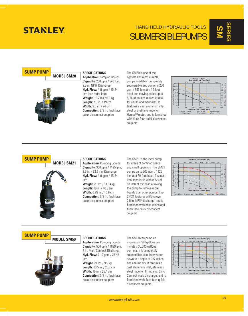
SUMP PUMPMODEL SM20
SPECIFICATIONSApplication: Pumping LiquidsCapacity: 250 gpm / 946 lpm, 2.5 in. NPTF DischargeHyd. Flow: 4-9 gpm / 15-34 lpm (see order info)Weight: 13.7 lbs / 6.3 kgLength: 7.5 in. / 19 cmWidth: 9.6 in. / 24 cmConnection: 3/8 in. flush face quick disconnect couplers
The SM20 is one of the lightest and most durable pumps available. Completely submersible and pumping 250 gpm / 946 lpm at a 10-foot head and moving solids up to 5/16 of an inch makes it ideal for vaults and manholes. It features a cast aluminum inlet, steel or urethane impeller, Hyrevz™ motor, and is furnished with flush face quick disconnect couplers.
SPECIFICATIONSApplication: Pumping Liquids.Capacity: 300 gpm / 1125 lpm, 2.5 in. / 63.5 mm DischargeHyd. Flow: 4-9 gpm / 15-34 lpmWeight: 20 lbs / 11.34 kgLength: 16 in. / 40.6 cmWidth: 6.25 in. / 15.9 cmConnection: 3/8 in. flush face quick disconnect couplers
The SM21 is the ideal pump for areas of confined space and small openings. The SM21 pumps up to 300 gpm / 1125 lpm at a 50-foot head. The cast iron impeller is within 3/4 of an inch of the base allowing the pump to remove more liquids than other pumps. The SM21 features a lifting eye, 2.5 in. NPTF discharge, and is furnished with hose whips and flush face quick disconnect couplers.
SPECIFICATIONSApplication: Pumping LiquidsCapacity: 500 gpm / 1890 lpm, 3 in. Male Camlock DischargeHyd. Flow: 7-12 gpm / 26-45 lpmWeight: 21 lbs / 9.5 kgLength: 10.5 in. / 26.7 cmWidth: 10 in. / 25.4 cmConnection: 3/8 in. flush face quick disconnect couplers
The SM50 can pump an impressive 500 gallons per minute / 30,000 gallons per hour. It is completely submersible, can draw water down to a depth of 3.5 inches, and can run dry. It features a cast aluminum inlet, stainless steel impeller, lifting eye, 3 inch Camlock male discharge, and is furnished with flush face quick disconnect couplers.
0.00
Discharge Flow of Water (gpm)
Dis
char
ge H
ead
of W
ater
(fee
t)
Discharge Flow of Water (lpm)
Dis
char
ge H
ead
of W
ater
(met
ers)
7 gpm / 26 lpm 8 gpm / 30 lpm 9 gpm / 34 lpm 10 gpm / 38 lpm
20.0
40.0
60.0
80.0
100.0
120.0
0
5
10
15
20
25
30
35
0 50 100 150 200 250 300 350 400 450 500 550 600
0 200 400 600 800 1000 1200 1400 1600 1800 2000 2200
0.0
Discharge Flow of Water (gpm)
Dis
char
ge H
ead
of W
ater
(fee
t)
Discharge Flow of Water (lpm)
Dis
char
ge H
ead
of W
ater
(met
ers)
4 gpm/15 lpm 5 gpm/19 lpm 6 gpm/23 lpm 7 gpm/26 lpm 8 gpm/30 lpm
20.0
40.0
60.0
80.0
100.0
120.0
0
5
10
15
20
25
30
35
0 50 100 150 200 250 300 350 400
0 200 400 600 800 1000 1200 1400
Discharge Flow of Water (gpm)
Dis
char
ge H
ead
of W
ater
(fee
t)
SM20531 *SM20521Discharge Flow of Water (lpm)
Dis
char
ge H
ead
of W
ater
(met
ers)
0.0
20.0
40.0
60.0
80.0
100.0
120.0
140.0
0 50 100 150 200 250 3000
5
10
15
20
25
30
35
40
0 200 400 600 800 1000
6 gpm / 23 lpm*4 gpm / 15 lpm
7 gpm / 26 lpm*5 gpm / 19 lpm
8 gpm / 30 lpm*6 gpm / 23 lpm
MODEL SM21
MODEL SM50
SUMP PUMP
SUMP PUMP

www.stanleyhydraulics.com www.stanleyhydraulics.com30
HAND HELD HYDRAULIC TOOLS
SUBMERSIBLE TRASH PUMPSSER
IES
TP
TRASH PUMPMODEL TP03
SPECIFICATIONSApplication: Pumping liquids with Solids up to 4 in.Capacity: 800 gpm / 3028 lpm, 4 in. Male Camlock DischargeHyd. Flow: 7-9 gpm / 26-34 lpmWeight: 59 lbs / 26.7 kgLength: 19 in. / 48.3 cmWidth: 15 in. / 38 cmConnection: 3/8 in. flush face quick disconnect couplers
The TP08 is a heavy duty submersible trash pump capable of pumping high volumes of water, sand slurries, gravel, sludge and solids up to 4 inches in diameter. It features a steel bowl, cast iron impeller, polyethylene wear plates, carrying handle, removable top plate, 4 inch male Camlock discharge, and flush face quick disconnect couplers.
SPECIFICATIONSApplication: Pumping Liquids with Solids up to 3 in.Capacity: 450 gpm / 1688 lpm, 3 in. NPTF DischargeHyd. Flow: 7-9 gpm / 26-34 lpmWeight: 32 lbs / 14.52 kgLength: 14 in. / 35.5 cmWidth: 12 in. / 30.4 cmConnection: 3/8 in. flush face quick disconnect couplers
The TP03 is a submersible trash pump and will pump liquids with concentrations of solids up to 25% by volume. It features a tough urethane bowl and impeller, lifting eye, removable top plate, 3 inch NPTF discharge, and flush face quick disconnect couplers.
Model Part No. Description
SM20/SM21/SM50
02183 Fire Hose, 25 in. x 2-1/2 in.
02317 Fire Nozzle - 1 in. output
05133 2-1/2 in. Thread Adaptor for Sump Pump to Fire Hose
05134 50 ft. Fire Hose, 2-1/2 in. dia.
05135 Spanner Wrench for Pin Lug Coupler
15248 Adapter, 3 in. female camlock x male fire hose (nh) thread
59101 Adapter, 2-1/2 in. male NPT x 3 in. male Camlock
Model Part No. Description
SM20/SM21/SM50
56761 Discharge Hose
52720 3 in. Adapter
02812 Elbow
TP03
52720 Adapter, 3 in. male NPT x 3 in. male Camlock
56761 Lay-Flat Discharge Hose, 3 in. x 25 ft with Camlock fittings
TP08 65624 Lay-Flat Discharge Hose, 4 in. x 25 ft with Camlock Fittings
SUBMERSIBLE PUMP ACCESSORIES
Model Part No. Weight Length Width Flow Range Working PressureFull Relief
Setting Output Discharge Impeller
SM20
SM2043101 18 lbs / 8.16 kg 7.5 in. / 19 cm 9.6 in. / 24 cm 4-9 gpm / 15-34 lpm 1000-2000 psi / 70-140 bar 2250 psi / 155 bar 250 gpm / 946 lpm 2.5 in. / 63.5 mm Steel
SM2052101 18 lbs / 8.16 kg 7.5 in. / 19 cm 9.6 in. / 24 cm 4-6 gpm / 15-23 lpm 1000-2000 psi / 70-140 bar 2250 psi / 155 bar 250 gpm / 946 lpm 2.5 in. / 63.5 mm Urethane
SM2053101 18 lbs / 8.16 kg 7.5 in. / 19 cm 9.6 in. / 24 cm 4-9 gpm / 15-34 lpm 1000-2000 psi / 70-140 bar 2250 psi / 155 bar 250 gpm / 946 lpm 2.5 in. / 63.5 mm Urethane
SM21 SM2151101 25 lbs / 11.34 kg 16 in. / 40.6 cm 6.25 in. / 15.9 cm 4-9 gpm / 15-34 lpm 1000-2000 psi / 70-140 bar 2250 psi / 155 bar 300 gpm / 1125 lpm 2.5 in. / 63.5 mm Steel
SM50 SM50100 21 lbs / 9.5 kg 10.5 in. / 26.7 cm 10 in. / 25.4 cm 7-12 gpm / 26-45 lpm 1000-2000 psi / 70-140 bar 2250 psi / 155 bar 500 gpm / 1890 lpm 3 in. / 75 mm Steel
TP03 TP0300301 32 lbs / 14.52 kg 14 in. / 35.5 cm 12 in. / 30.4 cm 7-9 gpm / 26-34 lpm 2000 psi / 140 bar 2250 psi / 155 bar 450 gpm / 1688 lpm 3 in. / 75 mm Urethane
TP08 TP08013 65 lbs / 29.48 kg 19 in. / 48.3 cm 15 in. / 38 cm 7-9 gpm / 26-34 lpm 2000 psi / 140 bar 2250 psi / 155 bar 800 gpm / 3028 lpm 4 in. / 100 mm Steel
SUBMERSIBLE PUMPS
0.00
Discharge Flow of Water (gpm)
Dis
char
ge H
ead
of W
ater
(fee
t)
Discharge Flow of Water (lpm)
Dis
char
ge H
ead
of W
ater
(met
ers)
7 gpm / 26 lpm 8 gpm / 30 lpm 9 gpm / 34 lpm
20.0
40.0
60.0
80.0
100.0
120.0
50 100 150 200 250 300 350 400 450 5000
5
10
15
20
25
30
350 200 400 600 800 1000 1200 1400 1600 1800
0.0
10.0
20.0
30.0
40.0
50.0
0 100 200 300 400 500 600 700 800 900 1000
Discharge Flow of Water (gpm)
Dis
char
ge H
ead
of W
ater
(fee
t)
0
2
4
6
8
10
12
14
0 500 1000 1500 2000 2500 3000 3500
Discharge Flow of Water (lpm)
Dis
char
ge H
ead
of W
ater
(met
ers)
7 gpm / 26 lpm 8 gpm / 30 lpm 9 gpm / 34 lpm
MODEL TP08TRASH PUMP

www.stanleyhydraulics.com www.stanleyhydraulics.com 31
HAND HELD HYDRAULIC TOOLS
VENT FANS
SERIES
VF
VENT FANMODEL VF80 SPECIFICATIONS
Application: Ventilating large spaces such as vaults.Capacity: 1700 scfm / 802 lsecHyd. Flow: 4-12 gpm / 15-45 lpmWeight: 19 lbs / 8.6 kgLength: 15 in. / 40 cmWidth: 19 in. / 49 cmConnection: 3/8 in. flush face quick disconnect couplers
FEATURES• Designed for heavy duty service• Quiet operation• Centrifugal blower to deliver large volume of air• High impact plastic case• Standard 8 inch / 20 cm discharge• Accepts standard heaters and coolers• Hyrevz™ motor
Model Part No. Weight Length Width Flow RangeWorking Pressure
Full Relief Setting Capacity
VF80 VF8000 19 lbs / 8.6 kg 15 in. / 40 cm 19 in. / 49 cm 4-12 gpm / 15-45 lpm
1000-2000 psi / 70-140 bar
2250 psi / 155 bar 1700 scfm / 802 Isec
VENT FAN
VENT FAN ACCESSORIES
Model Part No. Description
VF80 04430 Flexible Exhaust Hose

www.stanleyhydraulics.com www.stanleyhydraulics.com32
HAND HELD HYDRAULIC TOOLS
POWER UNITSSER
IES
HP
Powering hydraulic tools doesn’t require a large pull-behind power source like an air compressor. The fact is, a power supply about the size of a wheelbarrow, such as our HP28 Power Unit, is more than sufficient to operate any tool shown in this catalog from our biggest breakers to our smallest drills.
Our hydraulic power units use the latest in commercial engine technology from manufacturers such as Briggs & Stratton and Honda. These engines are air cooled, fuel efficient, light weight, rugged, and pack plenty of power to operate our most demanding tools without over-taxing the engine.
Check out the advantages of hydraulic power units over other types of equipment such as air compressors or engine driven tools:
LIGHTER THAN AIR
• Versatile - dozens of tools can be operated from these power units• Air cooled - no winter freezing considerations• Fuel efficient - 1.3 gallons per hour / 4 liters per hour estimated fuel
consumption• Quiet operation
• Lightweight - 149 to 360 lbs / 68 to 163 kg• Small size - can fit into small truck or van• Portable - can be wheeled around jobsite like a wheelbarrow• Serviceability - can be serviced by small engine dealers
POWER UNITMODEL HP28 (TWIN 8)
The New HP28 (TWIN8) twin circuit hydraulic power unit offers a revolutionary design capable of operating two tools at 8 gpm simultaneously. For the first time running two hydraulic tools at full 8 gpm capacity is a reality, increasing productivity and versatility like never before. Experience how the HP28 will change the way hydraulic tools are used and JOIN THE REVOLUTION!
Each of the two circuits is optimized to deliver ideal flows and pressures to both Type 1 and Type 2 hydraulic tools.
SPECIFICATIONSApplications: Heavy-duty continuous use hydraulic power supply for up to 2 tools both Type 1 and Type 2Capacity: 2 each 5 or 8 gpm / 2 each 20 or 30 lpmPressure: 2000 psi / 140 barWeight: 360 lb / 163 kgLength: 37.5 in. / 95.3 cmWidth: 25.75 in. / 65.4 cmHeight: 30 in. / 76.2 cmEngine: Briggs & Stratton 27 hpConnection: 3/8 in. flush face quick disconnect couplersHeat Rejection: Up to 9 hp use of two with both 1 & 2 Type tools
FEATURES• ATM Technology Active Thermal Management (ATM) op-
timizes performance in extreme weather conditions. By managing oil temperatures, preheat time is decreased and tool run-time increases.
• Side Handles New side handles improve ease of lifting
the unit while adding side impact protec-tion and with no moving parts to wear or corrode.
• Solid Tires Eliminates the need to refill flat tires and
decreases pull force needed for maneu-vering.
• Recessed Control Panel Protects dashboard and couplers.• Tough Grip Multi Position Handle Special Tough Grip handle surface
improves comfort and control with increased durability.
• Lifting Hook Flush face design protects the lifting hook
from accidental job abuse.• Auto Choke Allows for quick and easy starting of the
power unit.

www.stanleyhydraulics.com www.stanleyhydraulics.com 33
HAND HELD HYDRAULIC TOOLS
POWER UNITS
SERIES
HP
The HP28 power unit is ideal for municipal applications like servicing water main breaks. With the HP28 both the pipe cutting and water pumping can be performed off a single power unit. No more having to compromise tool performance with gas or electric saws and pumps, now the high performance of hydraulic tools is not limited to just one tool at a time!
And with the light weight and small footprint of the HP28, it goes anywhere work needs to be done.

www.stanleyhydraulics.com www.stanleyhydraulics.com34
HAND HELD HYDRAULIC TOOLS
POWER UNITSSER
IES
GT
POWER UNITMODEL GT18
The GT18 hydraulic power unit is engineered for continuous professional use and is optimized to deliver ideal flows and pressures to both Type 1 and Type 2 hydraulic tools. Its powerful 18 HP Briggs & Stratton engine and best-in-class cooling system deliver the power and heat rejection pros need to keep tools working uninterrupted all day in all types of conditions. The GT18 features a computerized all-electric throttle control system that idles-down the engine when tools aren’t running, saving fuel and extending service life. Its feature-rich, dependable operation make the GT18 the workhorse of the industry.
SPECIFICATIONSApplication: Heavy-duty continuous use hydraulic power supply for use with both Type 1 & Type 2 toolsCapacity: 5 or 8 gpm / 20 or 30 lpmPressure: 2000 psi / 140 barWeight: 330 lbs / 150 kg (Briggs & Stratton model)Length: 35 in. / 90 cmWidth: 21.5 in. / 54.6 cmHeight: 29 in. / 73.7 cm
Engine: Briggs & Strattion 18 hp Vanguard Connection: 3/8 in. flush face quick disconnect couplersHeat Rejection: Up to 5 hp
FEATURES• Meets HTMA requirements for Type 1
and Type 2 hydraulic tool circuits. • 5 or 8 gpm / 20 or 30 lpm @ 2000 psi • Heat rejection capacity exceeding 5 hp.• Computerized throttle control • Quartz hour meter• Direct mounted hydraulic pump• Air-oil cooler• Lift and latch handle• Pneumatic tires• Maintenance-free battery• Hydraulic and engine oil filter• Engine oil level shut-down• 5 gallon / 20 liters fuel capacity
POWER UNITMODEL GT23
The GT23 hydraulic power unit is engineered for continuous professional use and is optimized to deliver ideal flows and pressures to both Type 2 and Type 3 hydraulic tools. Its powerful 23 HP Briggs & Stratton engine and best-in-class cooling system deliver the power and heat rejection pros need to keep tools working uninterrupted all day in all types of conditions. The GT23 features a computerized all-electric throttle control system that idles-down the engine when tools aren’t running, saving fuel and extending service life. Its feature-rich, dependable operation make the GT23 the industry choice for high-flow applications.
SPECIFICATIONSApplication: Heavy-duty continuous use hydraulic power supply for both Type 2 & Type 3 toolsCapacity: 8 or 12 gpm / 30 or 45 lpmPressure: 2000 psi / 140 barWeight: 340 lbs / 154 kgLength: 35 in. / 90 cmWidth: 21.5 in. / 54.6 cmHeight: 29 in. / 73.7 cmEngine: Briggs & Strattion 23 hp Vanguard
Connection: 3/8 in. flush face quick disconnect couplersHeat Rejection: Up to 5 hp
FEATURES• Meets HTMA requirements for Type 2
and Type 3 hydraulic tool circuits. • 8 or 12 gpm / 30 or 45 lpm @ 2000 psi • Heat rejection capacity exceeding 5 hp.• Computerized throttle control • Quartz hour meter• Direct mounted hydraulic pump• Air-oil cooler• Lift and latch handle• Pneumatic tires• Maintenance-free battery• Hydraulic and engine oil filter• Engine oil level shut-down,• 5 gallon / 20 liters fuel capacity
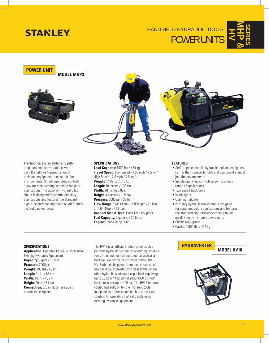
www.stanleyhydraulics.com www.stanleyhydraulics.com 35
HAND HELD HYDRAULIC TOOLS
POWER UNITS
SERIES
MHP &
HV
MODEL GT23
POWER UNITMODEL MHP3
SPECIFICATIONSLoad Capacity: 1000 lbs / 454 kg Travel Speed: Low Speed - 1.55 mph / 2.5 km/hHigh Speed - 2.8 mph / 4.5 km/hWeight: 1125 lbs / 510 kgLength: 78 inches / 198 cmWidth: 36 inches / 92 cmHeight: 43 inches / 109 cmPressure: 2000 psi / 38 barFlow Range: Twin Circuit - 2 @ 5 gpm / 20 lpm or 1 @ 10 gpm / 38 lpm Connect Size & Type: Flush-Face CouplersFuel Capacity: 5 gallons / 20 litersEngine: Honda 20 hp OHV
FEATURES• Self-propelled mobile hydraulic tool and equipment
carrier that transports tools and equipment in most job-site environments
• Simple operating controls allow for a wide range of applications
• Two speed track drive• Work lights• Opening tailgate• Auxiliary hydraulic tool circuit is designed
for continuous-duty applications and features the standard high-efficiency cooling found on all Stanley hydraulic power units
• Climbs 60% grade• Carries 1,000 lbs / 454 kg
The TracHorse is an all-terrain, self-propelled mobile hydraulic power pack that allows transportation of tools and equipment in most job site environments. Simple operating controls allow for maneuvering in a wide range of applications. The auxiliary hydraulic tool circuit is designed for continuous-duty applications and features the standard high-efficiency cooling found on all Stanley hydraulic power units.
SPECIFICATIONSApplication: Operates Hydraulic Tools using Existing Hydraulic Equipment.Capacity: 8 gpm / 30 lpmPressure: 2000 psiWeight: 100 lbs / 45 kgLength: 21 in. / 53 cmWidth: 19 in. / 48 cmHeight: 20 in. / 51 cmConnection: 3/8 in. flush face quick disconnect couplers
The HV18 is an efficient, clean air-oil cooled portable hydraulic system for operating hydraulic tools from another hydraulic source such as a backhoe, excavator, or skidsteer loader. The HV18 obtains its power from the hydraulics of any backhoe, excavator, skidsteer loader or any other hydraulic equipment capable of supplying up to 35 gpm / 132 lpm at 2000-3000 psi with back-pressures up to 400 psi. The HV18 features cooled hydraulic oil for the hydraulic tools independent of the source oil. It is the perfect solution for operating hydraulic tools using existing hydraulic equipment.
HYDRAVERTERMODEL HV18
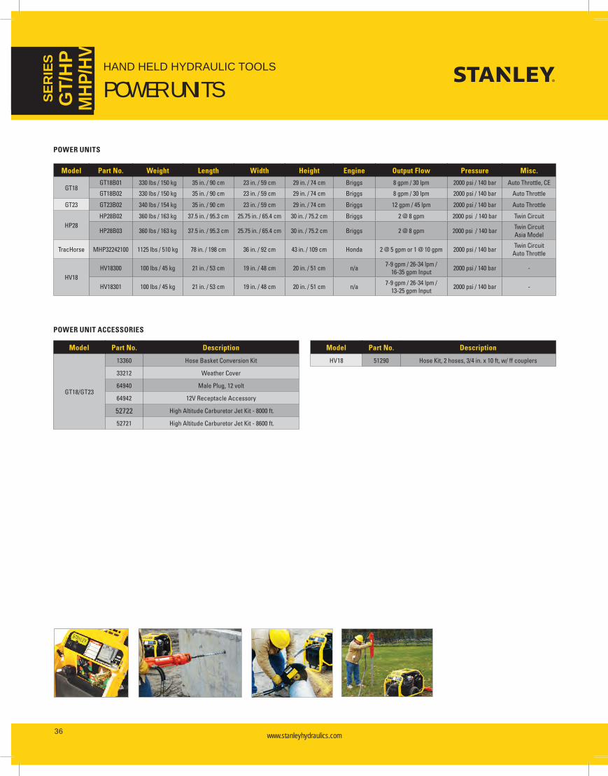
www.stanleyhydraulics.com www.stanleyhydraulics.com36
HAND HELD HYDRAULIC TOOLS
POWER UNITSSER
IES
GT/
HP
MHP
/HV
Model Part No. Weight Length Width Height Engine Output Flow Pressure Misc.
GT18GT18B01 330 lbs / 150 kg 35 in. / 90 cm 23 in. / 59 cm 29 in. / 74 cm Briggs 8 gpm / 30 lpm 2000 psi / 140 bar Auto Throttle, CE
GT18B02 330 lbs / 150 kg 35 in. / 90 cm 23 in. / 59 cm 29 in. / 74 cm Briggs 8 gpm / 30 lpm 2000 psi / 140 bar Auto Throttle
GT23 GT23B02 340 lbs / 154 kg 35 in. / 90 cm 23 in. / 59 cm 29 in. / 74 cm Briggs 12 gpm / 45 lpm 2000 psi / 140 bar Auto Throttle
HP28HP28B02 360 lbs / 163 kg 37.5 in. / 95.3 cm 25.75 in. / 65.4 cm 30 in. / 75.2 cm Briggs 2 @ 8 gpm 2000 psi / 140 bar Twin Circuit
HP28B03 360 lbs / 163 kg 37.5 in. / 95.3 cm 25.75 in. / 65.4 cm 30 in. / 75.2 cm Briggs 2 @ 8 gpm 2000 psi / 140 bar Twin CircuitAsia Model
TracHorse MHP32242100 1125 lbs / 510 kg 78 in. / 198 cm 36 in. / 92 cm 43 in. / 109 cm Honda 2 @ 5 gpm or 1 @ 10 gpm 2000 psi / 140 bar Twin Circuit Auto Throttle
HV18HV18300 100 lbs / 45 kg 21 in. / 53 cm 19 in. / 48 cm 20 in. / 51 cm n/a 7-9 gpm / 26-34 lpm /
16-35 gpm Input 2000 psi / 140 bar -
HV18301 100 lbs / 45 kg 21 in. / 53 cm 19 in. / 48 cm 20 in. / 51 cm n/a 7-9 gpm / 26-34 lpm / 13-25 gpm Input 2000 psi / 140 bar -
POWER UNITS
Model Part No. Description
GT18/GT23
13360 Hose Basket Conversion Kit
33212 Weather Cover
64940 Male Plug, 12 volt
64942 12V Receptacle Accessory
52722 High Altitude Carburetor Jet Kit - 8000 ft.
52721 High Altitude Carburetor Jet Kit - 8600 ft.
Model Part No. Description
HV18 51290 Hose Kit, 2 hoses, 3/4 in. x 10 ft, w/ ff couplers
POWER UNIT ACCESSORIES

www.stanleyhydraulics.com www.stanleyhydraulics.com 37
HAND HELD HYDRAULIC TOOLS
ACCESSORIES
Part No. Description
04722 9 gpm flow control, Brand Hydraulics, C-50-9
72264 In-line Valve, OC/CC
Part No. Description
67259 Check Valve Assembly
67005 Tool Exchange Valve
HYDRAULIC VALVES & FLOW CONTROLS
QUICK DISCONNECT COUPLERS
Part No. Description
03288 3/8 Cap & Plug for all flush face sets
03971 3/8 Parker Flush Face Set (3/8 NPT)
03974 Parker Flush Face Set (1/2 NPT)
Part No. Description
00936 Adapter, 1/2 SAE to 3/8 in. male pipe
Part No. Description
04192 Hex Nipple, 1/2 in. male pipe
PLUMBING
Part No. Description
02835 Accumulator Tester & Charger
04182 Flow and Pressure Tester
TEST EQUIPMENT
Part No. Description
29085 Flow & Pressure Tester
31254 Accumulator Charging Kit (hand held tools only)
Part No. Description
01412 Pigtail Hose Whip, 3/8 in. ID x 12 in., 3/8 in. male pipe, -6 SAE O-ring.
01652 Pigtail Hose Whip, 1/2 in. ID x 12 in., 3/8 male pipe, -8 SAE O-ring
05005 10 ft. certified non-conductive, dual oil resistant pig-tails, 3/8 in. NPT male fittings with guard
05120 Clear Vinyl Hose Guard (per ft.)
31848 50 ft. x 1/2 in. ID wire braid, dual hose with couplers
31972 25 ft. x 1/2 in. ID wire braid, dual hose with couplers
44931 Rubber hose, non-conductive, 3/8 in. x 8 ft
47318 Rubber hose, non-conductive, 3/8 in. x 10 ft
Part No. Description
56797 Rubber Hose Set, non-conductive, 3/8 in. x 10 ft, w/couplers
65897 Rubber Hose Set, non-conductive, 3/8 x 14 ft, w/couplers
58633 Twinned Hose, 1/2 in. x 25 ft, wire braid, w/couplers
58634 Twinned Hose, 1/2 in. x 50 ft, wire braid, w/couplers
58973 Rubber Hose Set, non-conductive, 3/8 in. x 8 ft, w/couplers
65617 Rubber Hose Set, non-conductive, 3/8 in. x 10 ft, -8 male SAE x 3/8 NPTF Male
71170 Non-Conductive, twin-line bonded coiled hose, 3/8 in. NPT
HYDRAULIC HOSES
www.stanleyhydraulics.com www.stanleyhydraulics.com38
HAND HELD HYDRAULIC TOOLS
HYDRAULIC SYSTEM REQUIREMENTS
Hydraulic systems come in many forms—from those found in the simple hydraulic jack to the more sophisticated systems found in earth moving equipment. The system required to operate most hydraulic tools found in this catalog would require 8 gpm / 30 lpm and be capable of providing system pressure up to 2000 psi / 140 bar. This system is referred to as a Type II, as classified by the Hydraulic Tool Manufacturers Association (HTMA). But there are also 3 other classifications. They are discussed below.
HYDRAULIC TOOL MANUFACTURERS’ ASSOCIATION (HTMA) REQUIREMENTSHydraulic tools fall into 4 classifications, Type I, Type II, Type III, and Type RR as set by HTMA. The system requirements for powering these tools are as follows:
Type I 5 gpm ±10% / 19 lpm
Type II 8 gpm ±10% / 30 lpm
Type III 12 gpm ±10% / 45 lpm
Type RR 10 gpm ±10% / 38 lpm
OPERATING PRESSURE:
Hydraulic systems should be capable of providing the appropriate operating pressure and flow for the system types noted above when measured across the tool connections. Deviation from the nominal flow rates should be no more than plus or minus 10% at a operating pressure of 2000 psi / 138 bar. This is the pressure that the tools will normally operate at which is not to be confused with the relief pressure.
RELIEF PRESSURE:
Hydraulic systems should be capable of limiting the maximum pressure by using either a pressure compensating pump or a relief valve with a non-pressure compensating pump. The system pressure limiting component shall begin to control the maximum pressure at no less than 2150 psi. This is commonly known as the “cracking pressure”. The system pressure limiting component shall limit the maximum pressure to 2250 psi for a Type I, Type II, or Type III tool. The system pressure limiting component shall limit the maximum pressure to 2500 psi for a Type RR tool.
RETURN PRESSURE:
The hydraulic systems should generate no more than 250 psi / 17 bar return pressure (back pressure) at the tool when operating at maximum flow for the tool type. System conditions for this pressure are at maximum hydraulic fluid viscosity of 400 SUS (SSU) at minimum operating temperature.
COOLING:
The hydraulic systems should have sufficient heat rejection capacity to limit maximum oil temperature to 140° F / 60° C at the maximum expected ambient temperature. Recommended minimum cooling capacities to dissipate tool-generated heat are:
Type I 3 Horsepower / 2.24 kW
Type II 5 Horsepower / 3.73 kW
Type III 7 Horsepower / 5.22 kW
Type RR 6 Horsepower / 5.22 kW
When determining cooling capacity, the intended duty cycle and the system generated heat must both be considered.
FILTRATION:
Systems should have 25 micron nominal filtration for the hydraulic fluid. Recommended filter element size is at least three times system rated flow to prevent filter bypass under low temperature start-up.
FLUID:
Hydraulic systems should use hydraulic fluid that has a viscosity of 130-225 SSU / 27-42 cst at l00° F / 38° C. Hydraulic fluids of petroleum base with anti wear properties and high viscosity indexes over 140 will meet recommended hydraulic fluid requirements over a wide range of operating temperatures. They should be demulsifying type to allow water to settle out of the fluid.
www.stanleyhydraulics.com www.stanleyhydraulics.com 39
HAND HELD HYDRAULIC TOOLS
HYDRAULIC BASICS
OPEN-CENTER AND CLOSED-CENTER SYSTEMSThere are two basic types of hydraulic systems — Open-Center and Closed-Center.
OPEN-CENTER IS CONSTANT FLOW — VARIABLE PRESSURE
When a tool valve is in the OFF position, hydraulic oil flows through the ON/OFF valve ports of the tool and back to the reservoir. The system is constantly flowing oil through the tool valve ports and back to the reservoir at no pressure. When the tool valve is ON, oil circulates through the tool causing the tool to operate, and then returns to the reservoir. Pressure is created when resistance to flow is sensed by the system. This occurs when the tool is put to work. Pressure will increase as the tool needs it up to the relief setting in the hydraulic system.
CLOSED-CENTER IS CONSTANT PRESSURE — VARIABLE FLOW
When a tool valve is in the OFF position, hydraulic oil flow stops at the ON/ OFF valve port of the tool. The system will build and hold pressure without returning oil to the reservoir. When the tool valve is ON, oil circulates through the tool causing the tool to operate, and then returns to the reservoir. Pressure tends to be constant in the system. Pressure will increase as the tool needs it up to the settings in the hydraulic system. And if pressures higher than the system setting are demanded by the work, flow will decrease.
FLUID TEMPERATUREThe following information will serve to assist those installing hydraulics in mobile applications for hand held tools. While many hydraulic circuits can run upwards to 200° F / 93° C, temperatures over 110° F / 43° C are uncomfortable to human touch. Our desire is to hold oil temperature to a maximum of 140° F / 43° C.
In almost any hydraulic tool circuit, oil cooling methods will be required except for very short periods of operation or in underwater and extreme cold environments. If you are involved in the design of a hydraulic tool circuit, use the following as guidelines.
BASIC DON’TS FOR COOL OIL CONTROL
1. DON’T — Rely on a large reservoir to control oil heating. Large reservoirs, even with good air circulation, do not adequately dissipate heat.
2. DON’T — Set relief pressure too low (open-center circuits) for percussion type tools (breakers, hammer drills, etc.). Pressure peaks may run up to 350 PSI over gauge pressure, popping the relief and causing heat as well as low tool performance.
3. DON’T — Pump more oil than the tool should use and avoid flow controls if possible. Instead, size the pump for desired flow volume. Gear type flow dividers can be used to reduce flow more efficiently than valves, reducing heat.
4. DON’T — Use heavy oils such as 30W or 10W30 engine oils. These will cause resistance in lines and add to back pressure and heat.
5. DON’T — Run return oil through control valves or other circuit components, except coolers and return line filters.
DO THE FOLLOWING TO REDUCE HEAT GENERATION
1. Operate pumps at moderate speed — gear pumps usually generate less heat and are less prone to cavitation at speeds of 1,000-2,000 RPM.
2. Use generous line sizes — Especially on pump suction and return from tool to tank.
3. Use oils in 130-225 SSU at l00° F / 38° C range with high viscosity index. (see hydraulic fluid recommendations at the end of this section)
PROVIDE GOOD COOLING FOR HYDRAULIC OIL
1. Use an air-to-oil cooler of maximum size for space available. Use a shrouded, high capacity fan. Many vehicles do not cool well when parked with engine at low speed. Do NOT use a “thermal” viscous-drive fan because these fans do not draw air unless the engine is hot.
FLOW CONTROLS1. General Notes — To reduce or control flow rate through Stanley Tools,
flow control valves are sometimes necessary. All possible effort should be made to avoid use of flow control valves where appropriate pump volume can be used because:
A. Excess oil volume and subsequent pressure drop generates heat.
B. When percussion type tools that generate pressure pulses are used, flow controls may oscillate and cause flow changes which reduce tool performance and add increased heating.
2. Flow Control of Open-Center Circuits — Always use a priority type pressure-compensated flow control. This will prevent relief popping and reduce heat build-up. The excess flow should be routed in an unrestricted manner to the reservoir.
3. Flow Control of Closed-Center Circuits — Use a two-port, pressure-compensated flow control. Some of these are very compact, in the range of 1-1/4” diameter by 5” long, and can be attached to the tool pressure pigtail. Do not use priority type controls on closed-center circuits, as this will cause the pump to operate at full volume — further heating the oil.
QUICK DISCONNECTS1. Only use quick disconnects matching hose diameters. i.e. 1/2 inch
port quick disconnect for 1/2 inch inside diameter hose.
2. Use as few quick disconnects as possible and avoid using adapter fittings with quick disconnects. Fittings and quick disconnects, while necessary, create flow restriction which causes heat and reduced tool performance.
3. Always use HTMA recommended quick disconnects that are flush-faced and drip less.

www.stanleyhydraulics.com www.stanleyhydraulics.com40
HAND HELD HYDRAULIC TOOLS
HYDRAULIC BASICS
HOSE TYPESThe rated working pressure of the hydraulic hose must be equal to or higher than the relief valve setting on the hydraulic system. There are three types of hydraulic hose that meet this requirement and are authorized for use with Stanley Hydraulic Tools. They are:
• Certified non-conductive - constructed of thermoplastic or synthetic rubber inner tube, synthetic fiber braid reinforcement, and weather resistant thermoplastic or synthetic rubber cover. Hose labeled certified non-conductive is the only hose authorized for use near electrical conductors.
• Wire-braided (conductive) - constructed of synthetic rubber inner tube, single or double wire braid reinforcement, and weather resistant synthetic rubber cover. This hose is conductive and must never be used near electrical conductors.
• Fabric-braided (not certified or labeled non-conductive) - constructed of thermoplastic or synthetic rubber inner tube, synthetic fiber braid reinforcement, and weather resistant thermoplastic or synthetic rubber cover. This hose is not certified non-conductive and must never be used near electrical conductors.
RECOMMENDED HOSE CONFIGURATIONS
When a longer hose configuration is used by connecting hoses together, system back pressure is increased. Too high a back pressure may reduce performance and life of the tool. Stanley recommends back pressure not to exceed 250 psi / 17 bar. In addition, oil temperature should be limited to 140 degrees F / 60 degrees C.
For both 5 and 8 gpm (20 - 30 lpm) tools, standard hose with a 1/2” inside diameter is acceptable to use up to 100’ or 30 m when configured with (2) sets of 50 feet hose.
Stanley does not recommend the following configurations with 1/2” diameter hose.
• (4) sets of 25’ hose
• (1) set of 50’ hose + (2) sets of 25’ hose
These configuration will drive back pressure beyond recommended levels. For longer lengths between 100’ to 300’ Stanley recommends increasing the hose diameters to the following:
Pressure Line - 5/8” Inside Diameter Hose
Return Line - 3/4” Inside Diameter Hose
The increased hose diameter will alleviate back pressure and allow proper tool operation.
PERFORMANCE NOTES
When operating with longer hose lengths with the same diameter hose, back pressure increases. When operating hydraulic tools at 100’ with the 1/2” diameter hose, some decrease in performance is possible.
This should not noticeably affect overall performance of the tool, but note it is not under optimal conditions with longer hose configurations.
Oil Flow Each Hose Length Inside DiameterUSE Wire Braid
Hose Spec
Working PressureFiber BraidHose Spec
Operating Pressure
GPM LPM FEET METERS INCH MM PSI BAR PSI BAR
5-8 19-30 up to 50 up to 15 1/2 13 Both SAE 100R17-8 3000 230 SAE 100R7-8 2000 140
5-8 19-30 51-100 15-30 5/8 16 Both SAE 100R17-10 3000 230 SAE 100R8-10 2750 190
5-8 19-30 100-300 30-905/8 16 Pressure SAE 100R2-10 2750 190 SAE 100R8-10 2750 190
3/4 19 Return SAE 100R1-12 1250 86 SAE 100R7-12 1250 86
TOOL TO CIRCUIT HOSE RECOMMENDATIONS
NOTE: SAE 100R16 may be used in place of SAE 100R2
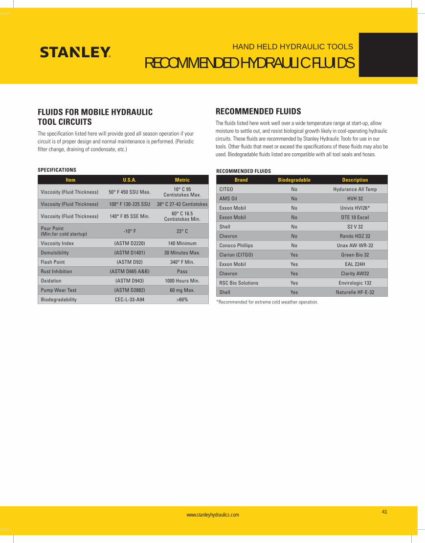
www.stanleyhydraulics.com www.stanleyhydraulics.com 41
HAND HELD HYDRAULIC TOOLS
RECOMMENDED HYDRAULIC FLUIDS
FLUIDS FOR MOBILE HYDRAULIC TOOL CIRCUITSThe specification listed here will provide good all season operation if your circuit is of proper design and normal maintenance is performed. (Periodic filter change, draining of condensate, etc.)
RECOMMENDED FLUIDSThe fluids listed here work well over a wide temperature range at start-up, allow moisture to settle out, and resist biological growth likely in cool-operating hydraulic circuits. These fluids are recommended by Stanley Hydraulic Tools for use in our tools. Other fluids that meet or exceed the specifications of these fluids may also be used. Biodegradable fluids listed are compatible with all tool seals and hoses.
Item U.S.A. Metric
Viscosity (Fluid Thickness) 50° F 450 SSU Max. 10° C 95 Centistokes Max.
Viscosity (Fluid Thickness) 100° F 130-225 SSU 38° C 27-42 Centistokes
Viscosity (Fluid Thickness) 140° F 85 SSE Min. 60° C 16.5 Centistokes Min.
Pour Point (Min.for cold startup) -10° F 23° C
Viscosity Index (ASTM D2220) 140 Minimum
Demulsibility (ASTM D1401) 30 Minutes Max.
Flash Point (ASTM D92) 340° F Min.
Rust Inhibition (ASTM D665 A&B) Pass
Oxidation (ASTM D943) 1000 Hours Min.
Pump Wear Test (ASTM D2882) 60 mg Max.
Biodegradability CEC-L-33-A94 >60%
SPECIFICATIONS
Brand Biodegradable Description
CITGO No Hydurance All Temp
AMS Oil No HVH 32
Exxon Mobil No Univis HVI26*
Exxon Mobil No DTE 10 Excel
Shell No S2 V 32
Chevron No Rando HDZ 32
Conoco Phillips No Unax AW-WR-32
Clarion (CITGO) Yes Green Bio 32
Exxon Mobil Yes EAL 224H
Chevron Yes Clarity AW32
RSC Bio Solutions Yes Envirologic 132
Shell Yes Naturelle HF-E-32
RECOMMENDED FLUIDS
*Recommended for extreme cold weather operation.

www.stanleyhydraulics.com www.stanleyhydraulics.com42
HAND HELD HYDRAULIC TOOLS
SYSTEM SPECIFICATIONS
HYDRAULIC SYSTEM SPECIFICATIONS SUITABLE FOR POWERING HTMA TYPE I HYDRAULIC TOOLS
GENERAL SPECIFICATIONS
The following specifications are for a hydraulic system which will deliver the performance of an HTMA Type 1 system. The HTMA Type 1 system has a flow requirement of 5 gpm, plus or minus 10%.
The hydraulic system shall be an open-center type system and deliver the design flow rate over a pressure load range of 1000 to 2000 psi. Alternatively, the system may be a closed-center type having the same hydraulic performance.
The system pressure limiting component shall begin to control at a pressure no less than 2150 psi / 148 bar and shall limit the maximum pressure to no more than 2250 psi / 155 bar. This component may be a relief valve, used with a non-pressure compensating pump system, or the pressure control used with a pressure-compensating pump system.
The flow loss in the return side of the system must be low enough so that the return pressure (back pressure), when measured at the tool end of the tool hose is not more than 250 psi / 17 bar. This measurement is to be made with the system at minimum operating temperature and the hydraulic oil viscosity no higher than 400 SSU / 86 cst. For ISO Grade 32 hydraulic oil, the system temperature will be approximately 50° F / 10° C.
The hydraulic system shall have sufficient heat rejection capacity to limit the maximum oil temperature to 140° F / 60° C at the maximum expected ambient temperature. The minimum cooling capacity to dissipate tool-generated heat is 3 hp / 7,635 BTU/hr. This cooling capacity may be modified taking into consideration intended tool operation duty cycle and system generated heat.
The hydraulic system shall have a return line filter rated for 25 micron nominal filtration. The filter shall have a flow capacity of at least 15 gpm.
The hydraulic system shall use a fluid which has a viscosity of 150-225 SSU / 32-50 cst at 100° F / 38° C. Hydraulic fluids of petroleum base with anti-wear properties and high viscosity indexes over 140 will meet fluid requirements over an wide range of operating temperatures.
DETAIL SPECIFICATIONS
The hydraulic reservoir shall be of a metal construction with a fluid holding capacity of 8 to 13 gallons. The reservoir shall include a vented filler/breather with a filter basket. It shall have a 140-mesh or 125 micron pump suction strainer located near the bottom and a rigid internal baffle to prevent direct cross flow from return to suction. The fluid return shall be below the lowest fluid level in order to prevent air entrainment. The reservoir shall include a fluid level indicator to show fluid level from the minimum requiring fill to the maximum showing full. It shall include a drain, low near the bottom, to provide for draining settled-out water or complete emptying of the reservoir. There shall be provision for access to the inside for servicing the suction strainer and cleaning the reservoir.
The fluid line from the reservoir to the pump suction port shall have an inside diameter of 1.25 inches / 32 mm.
The pump shall be sized to deliver the system design flow at a shaft speed determined by the prime mover speed and any speed reduction between it and the pump. For vehicles with automatic transmissions, the engine speed should be between 1700 and 2000 rpm. For example, if the power takeoff speed ratio is .75, then the pump speed will be 1275 to 1500 rpm. The pump displacement will be between 0.770 and 0.906 cubic inches per rev. For a fixed-displacement pump, these displacements will be that of the pump. For variable-displacement pumps, these displacements with be the pump displacement setting while operating the hydraulic tool system. The pump shall have a maximum pressure rating of at least 3000 psi.
The pressure line from the pump outlet to the directional valve shall have an inside diameter of 0.75 inches / 19 mm. The working pressure of the line shall be at least 2500 psi.
If no bi-directional tools will be used, the directional control valve shall be ¾-inch size two-position two-port or three-port diverter valve. Only the pressure side flow will go through the valve. For an open-center system, in the OFF position the valve will bypass flow to the system return; in the ON position the valve will block the bypass to the system return. For a closed-center system, in the OFF position the valve will block the pump port and connect the tool to the return; in the ON position the valve will connect the pump to the tool. It must be rated for working pressure of at least 2500 psi.
If bi-directional tools will be used, the directional control valve shall be a ¾-inch size three-position, four-port valve. The valve spool shall be a motor spool. For an open-center system, all ports must be connected to the tank port in the neutral position. For a closed-center system, the tool ports must be connected together. It must be rated for working pressure of at least 2500 psi.

www.stanleyhydraulics.com www.stanleyhydraulics.com 43
HAND HELD HYDRAULIC TOOLS
SYSTEM SPECIFICATIONS
The relief valve may be a separate component or integral to the directional control valve. It may be either direct operating or pilot operated. It shall be set with the cracking pressure at 2150 psi / 148 bar. The maximum full-flow bypass pressure shall not be more than 2250 psi / 155 bar.
The air-to-oil cooler must be sized and placed to have the required heat rejection capacity. If the vehicle engine does not have a temperature-controlled fan, the oil cooler may be mounted in front of the vehicle radiator. The cooler will be the largest that will cover the radiator and must be at least 1 ½ inches thick. The oil cooler must have low enough air flow resistance so as not to seriously reduce the vehicle cooling capacity. If the vehicle has a temperature-controlled fan, then an air-to-oil cooler with fan(s) must be selected. This cooler must be installed where it will have unimpeded air flow. The ports in the cooler shall be at least 1-inch size. Integral to the cooler or separately installed with the cooler shall be a bypass check valve or thermal diverter valve to allow fluid to bypass the cooler at low temperatures and high viscosities until the fluid temperature reaches working temperatures. If a thermal diverter valve is used, it should have a temperature setting between 85° and 95° F / 29° and 35° C. If a separately-fanned cooler is selected, it shall have a thermal switch to turn on the fan(s) when oil flows through the cooler.
The system return lines shall have an inside diameter of .75 or 1.00 inch. The lines shall have a working pressure rating of at least 250 psi.
The hydraulic system shall have HTMA flush-face quick-acting couplers for connecting tools to the system. The coupler nose shall be on the pressure port and the coupler body shall be on the return port. These will be located according to the requirements of the end-user.
All connections shall be assembled and sealed to assure there will be no leaks. All components shall be suitable for mobile hydraulic systems and have flow capacity and working pressures which meet the requirements of the system. All lines shall be installed and restrained to prevent contact with hot engine components and prevent fatigue failure due to vibration or abrasion. The system shall be flushed clean and filled with clean hydraulic fluid.
The system will be accepted after verification by the customer that the system performance meets specifications.
HYDRAULIC SYSTEM SPECIFICATIONS SUITABLE FOR POWERING HTMA TYPE II HYDRAULIC TOOLS
GENERAL SPECIFICATIONS
The following specifications are for a hydraulic system which will deliver the performance of an HTMA Type 2 system. The HTMA Type 2 system has a flow requirement of 8 gpm, plus or minus 10%.
The hydraulic system shall be an open-center type system and deliver the design flow rate over a pressure load range of 1000 to 2000 psi. Alternatively, the system may be a closed-center type having the same hydraulic performance.
The system pressure limiting component shall begin to control at a pressure no less than 2150 psi / 148 bar and shall limit the maximum pressure to no more than 2250 psi / 155 bar. This component may be a relief valve, used with a non-pressure compensating pump system, or the pressure control used with a pressure-compensating pump system.
The flow loss in the return side of the system must be low enough so that the return pressure (back pressure), when measured at the tool end of the tool hose is not more than 250 psi. This measurement is to be made with the system at minimum operating temperature and the hydraulic oil viscosity no higher than 400 SSU / 86 cst. For ISO Grade 32 hydraulic oil, the system temperature will be approximately 50° F / 10° C.
The hydraulic system shall have sufficient heat rejection capacity to limit the maximum oil temperature to 140° F / 60° C at the maximum expected ambient temperature. The minimum cooling capacity to dissipate tool-generated heat is 5 hp / 12,725 BTU/hr. This cooling capacity may be modified taking into consideration intended tool operation duty cycle and system generated heat.
The hydraulic system shall have a return line filter rated for 25 micron nominal filtration. The filter shall have a flow capacity of at least 25 gpm.
The hydraulic system shall use a fluid which has a viscosity of 150-225 SSU / 32-50 cst at 100° F / 38° C. Hydraulic fluids of petroleum base with anti-wear properties and high viscosity indexes over 140 will meet fluid requirements over an wide range of operating temperatures.
www.stanleyhydraulics.com www.stanleyhydraulics.com44
HAND HELD HYDRAULIC TOOLS
SYSTEM SPECIFICATIONS
DETAIL SPECIFICATIONS
The hydraulic reservoir shall be of a metal construction with a fluid holding capacity of 12 to 20 gallons. The reservoir shall include a vented filler/breather with a filter basket. It shall have a 140-mesh or 125 micron pump suction strainer located near the bottom and a rigid internal baffle to prevent direct cross flow from return to suction. The fluid return shall be below the lowest fluid level in order to prevent air entrainment. The reservoir shall include a fluid level indicator to show fluid level from the minimum requiring fill to the maximum showing full. It shall include a drain, low near the bottom, to provide for draining settled-out water or complete emptying of the reservoir. There shall be provision for access to the inside for servicing the suction strainer and cleaning the reservoir.
The fluid line from the reservoir to the pump suction port shall have an inside diameter of 1.25 inches / 32 mm.
The pump shall be sized to deliver the system design flow at a shaft speed determined by the prime mover speed and any speed reduction between it and the pump. For vehicles with automatic transmissions, the engine speed should be between 1700 and 2000 rpm. For example, if the power takeoff speed ratio is .75, then the pump speed will be 1275 to 1500 rpm. The pump displacement will be between 1.449 and 1.232 cubic inches per rev. For a fixed-displacement pump, these displacements will be that of the pump. For variable-displacement pumps, these displacements with be the pump displacement setting while operating the hydraulic tool system. The pump shall have a maximum pressure rating of at least 3000 psi.
The pressure line from the pump outlet to the directional valve shall have an inside diameter of 0.75 inches / 19 mm. The working pressure of the line shall be at least 2500 psi.
If no bi-directional tools will be used, the directional control valve shall be ¾-inch size two-position two-port or three-port diverter valve. Only the pressure side flow will go through the valve. For an open-center system, in the OFF position the valve will bypass flow to the system return; in the ON position the valve will block the bypass to the system return. For a closed-center system, in the OFF position the valve will block the pump port and connect the tool to the return; in the ON position the valve will connect the pump to the tool. It must be rated for working pressure of at least 2500 psi.
If bi-directional tools will be used, the directional control valve shall be a ¾-inch size three-position, four-port valve. The valve spool shall be a motor spool. For an open-center system, all ports must be connected to the tank port in the neutral position. For a closed-center system, the tool ports must be connected together. It must be rated for working pressure of at least 2500 psi / 172 bar.
The relief valve may be a separate component or integral to the directional control valve. It may be either direct operating or pilot operated. It shall be set with the cracking pressure at 2150 psi / 148 bar. The maximum full-flow bypass pressure shall not be more than 2250 psi / 155 bar.
The air-to-oil cooler must be sized and placed to have the required heat rejection capacity. If the vehicle engine does not have a temperature-controlled fan, the oil cooler may be mounted in front of the vehicle radiator. The cooler will be the largest that will cover the radiator and must be at least 1 ½ inches thick. The oil cooler must have low enough air flow resistance so as not to seriously reduce the vehicle cooling capacity. If the vehicle has a temperature-controlled fan, then an air-to-oil cooler with fan(s) must be selected. This cooler must be installed where it will have unimpeded air flow. The ports in the cooler shall be at least 1-inch size. Integral to the cooler or separately installed with the cooler shall be a bypass check valve or thermal diverter valve to allow fluid to bypass the cooler at low temperatures and high viscosities until the fluid temperature reaches working temperatures. If a thermal diverter valve is used, it should have a temperature setting between 80° and 90° F / 26° and 32° C. If a separately-fanned cooler is selected, it shall have a thermal switch to turn on the fan(s) when oil flows through the cooler.
The system return lines shall have an inside diameter of .75 or 1.00 inch. The lines shall have a working pressure rating of at least 250 psi.
The hydraulic system shall have HTMA flush-face quick-acting couplers for connecting tools to the system. The coupler nose shall be on the pressure port and the coupler body shall be on the return port. These will be located according to the requirements of the end-user.
All connections shall be assembled and sealed to assure there will be no leaks. All components shall be suitable for mobile hydraulic systems and have flow capacity and working pressures which meet the requirements of the system. All lines shall be installed and restrained to prevent contact with hot engine components and prevent fatigue failure due to vibration or abrasion. The system shall be flushed clean and filled with clean hydraulic fluid.
The system will be accepted after verification by the customer that the system performance meets specifications.

www.stanleyhydraulics.com www.stanleyhydraulics.com 45
HAND HELD HYDRAULIC TOOLS
SYSTEM SPECIFICATIONS
TESTING A HYDRAULIC SYSTEM FOR COMPARISON TO HTMA RECOMMENDATIONS
The objective of this test is to determine how your hydraulic system performance compares with HTMA (Hydraulic Tool Manufacturers Association) recommended hydraulic system performance.
To perform these tests, you will need a flow and pressure tester such as our P/N 04182 or P/N 29085 shown below and two thermometers (the P/N 29085 has a built-in thermometer).
HTMA RECOMMENDATIONS FOR A HYDRAULIC SYSTEM OPERATING TYPE I HYDRAULIC TOOLS:
• 5 gpm ± 10% / .5 gpm at 2000 psi measured at the tool inlet.
• 200 psi or less return pressure at 5.5 gpm—pressure measured at the tool outlet.
• Limit system temperature to 140° F on the hottest expected day. Choosing 100° F as the hottest expected day’s temperature, the hydraulic system must maintain a 40 degree temperature difference, air to oil. For example, if the ambient air temperature is 100° F, then the oil temperature should not exceed 140° F.
• To simulate tool-generated heat during operation, HTMA recommends using 3 hp, minimum. A reading of 1030 psi minimum at the flow and pressure tester will achieve the recommended 3 hp, minimum.
HTMA RECOMMENDATIONS FOR A HYDRAULIC SYSTEM OPERATING TYPE II HYDRAULIC TOOLS:
• 8 gpm ± 10% / .8 gpm at 2000 psi measured at the tool inlet.
• 200 psi or less return pressure at 8.8 gpm, pressure measured at the tool outlet.
• Limit system temperature to 140° F on the hottest expected day. Choosing 100° F as the hottest expected day’s temperature, the hydraulic system must maintain a 40 degree temperature difference, air to oil. For example, if the ambient air temperature is 100° F, then the oil temperature should not exceed 140° F.
• To simulate tool-generated heat during operation, HTMA recommends using 5 hp, minimum. A reading of 1100 psi minimum at 8 gpm at the flow and pressure tester will achieve the recommended 5 hp, minimum.
Select an open site where the air is relatively calm. Place one thermometer in the oil reservoir to measure the temperature of the circulating oil (surface mounted tank thermometers do not adequately measure the temperature of the bulk system oil). Hang the other thermometer in still air to measure the ambient air temperature.
Connect the flow and pressure tester to the tool hoses. Fully open the load valve on the tester.
Start up the system (with tool circuit control valve OFF) and warm the hydraulic fluid (if necessary) to a minimum of 50° F.
LOW TEMPERATURE AND MAXIMUM VISCOSITY BACK PRESSURE TEST
Turn ON the tool circuit control valve. Record oil temperature, ambient air temperature, flow rate, and back pressure.
Air: ________________ ° F
Oil: ________________ ° F
Flow rate: ________________ gpm
Back pressure: ________________ psi
Stanley P/N 04182 Stanley P/N 29085

www.stanleyhydraulics.com www.stanleyhydraulics.com46
HAND HELD HYDRAULIC TOOLS
SYSTEM SPECIFICATIONS
HYDRAULIC SYSTEM’S CAPACITY TO DELIVER FLOW AGAINST 2000 PSI TEST
Close the load valve to where the pressure gage reads 2000 psi. Record flow rate, back pressure, and oil temperature.
Flow rate: ________________ gpm
Back pressure: ________________ psi
Oil: ________________ ° F
SYSTEM CAPACITY TO CONTROL TEMPERATURE TEST
Raise the system temperature to 140° F by adjusting the pressure using the load valve on the flow and pressure tester. If it takes more than 1900 psi to get the system temperature to 140° F, adjust the pressure to stabilize the system temperature at some lower temperature, e.g. 120° F.
When the system temperature has remained constant for about 15 minutes, record the flow rate, pressure, back pressure, oil temperature, and air temperature.
Flow rate: ________________ gpm
Pressure: ________________ psi
Back pressure: ________________ psi
Air: ________________ ° F
Oil: ________________ ° F
CALCULATE THE TOOL LOAD HP COOLING CAPACITY FOR AN EFFECTIVE 40 DEGREE TEMPERATURE DIFFERENCE, AIR TO OIL USING THE FOLLOWING FORMULA.
(Pressure – Back pressure) x gpm = hp (horse power) 43 x (Oil temperature – Air Temperature)
Example: Flow rate: 5 gpm
Pressure: 1500 psi
Back pressure: 100 psi
Air: 70 ° F
Oil: 120 ° F
(1500 – 100) x 5 = 3.3 hp at 40° F 43 x (120 – 70) temperature difference

www.stanleyhydraulics.com www.stanleyhydraulics.com 47
HAND HELD HYDRAULIC TOOLS
HYDRAULIC TOOLS
For more information on Stanley Hydraulic Tools,
please call our Milwaukie, OR facility at: 800-972-2647 or visit our web site at: www.stanleyhydraulics.com
MORE POWER TO YOUMOUNTED BREAKERS
Our mounted breakers feature industry leading design innovations including a patented valving system which provides unmatched
performance and durability, a unique, direct-acting nitrogen chamber that results in increased impact force with the simplicity of only two
moving parts and a rugged housing and powercell designed to excel in the most demanding applications. Our mounted breakers are ideal
for construction, demolition and quarry applications and are backed by one of the most trusted names in the industry.
CYCLONE DROP HAMMER
The Cyclone Drop Hammer is hands down, pound for pound, the most productive tool for breaking concrete flatwork. It is extremely simple to
install, use and maintain. The Cyclone can be mounted to skid steers, small excavators and rubber tire backhoe loaders. Since it sits directly
on top of the material using no down pressure, the energy produced by the hammer’s drop is concentrated on the material itself, causing
very little shock energy to go back into the machine. This significantly reduces fatigue to the machine and the operator.
MOUNTED COMPACTORS
Stanley Mounted Compactors are available to match applications requiring 2,500 to 22,000 pounds of vibratory force. The complete line
includes models to fit virtually any base machine from skid steers and mini-excavators to crawler excavators. The rugged construction
of Stanley Mounted Compactors features direct drive, heavy duty gear motor and patented baseplate design with outboard rubber shock
mounts to ensure longer service life.
LABOUNTY ATTACHMENTS
Stanley’s LaBounty shears, grapples, & pulverizers are coveted fixtures at construction, demolition, and scrap recycling job sites throughout
the world. Our attachments--some as old as the company itself--have stood atop the industry for more than 30 years and are recognized as
the utmost in quality, durability, and lasting performance.
HAND HELD HYDRAULIC TOOLS
Hydraulic Hand held Tools from Stanley increase job versatility and get the job done quickly, effectively and quietly. Hydraulic power is the
most efficient power of any traditional power source with the highest power-to-weight ratio of any power tool. Our hand held line of tools
can be powered from a variety of hydraulic power sources such as backhoes, aerial lifts, dump trucks and Stanley Hydraulic Power Units,
including our new mobile power unit – the TracHorse.
Stanley Hydraulic Tools makes a variety of hand held hydraulic tools for electric utilities, underwater applications, and other industries, as well as mounted breakers, compactors,
grapples and shears, providing the broadest lineup of hydraulic-powered tools in the industry. Visit www.stanley-hydraulic-tools.com for a complete listing.

Your Authorized Stanley Dealer
Hydraulic Tools Product Group
3810 SE Naef RoadMilwaukie, OR 97267 USATel. +1 503.659.5660Fax +1 503.652.1780
www.stanleyhydraulics.com
HH1.2015-2016


