

35010529 05/2010
3501
0529
.07
www.schneider-electric.com
Quantum with Unity ProHardwareReference Manual
05/2010

The information provided in this documentation contains general descriptions and/or technical characteristics of the performance of the products contained herein. This documentation is not intended as a substitute for and is not to be used for determining suitability or reliability of these products for specific user applications. It is the duty of any such user or integrator to perform the appropriate and complete risk analysis, evaluation and testing of the products with respect to the relevant specific application or use thereof. Neither Schneider Electric nor any of its affiliates or subsidiaries shall be responsible or liable for misuse of the information contained herein. If you have any suggestions for improvements or amendments or have found errors in this publication, please notify us.
No part of this document may be reproduced in any form or by any means, electronic or mechanical, including photocopying, without express written permission of Schneider Electric.
All pertinent state, regional, and local safety regulations must be observed when installing and using this product. For reasons of safety and to help ensure compliance with documented system data, only the manufacturer should perform repairs to components.
When devices are used for applications with technical safety requirements, the relevant instructions must be followed.
Failure to use Schneider Electric software or approved software with our hardware products may result in injury, harm, or improper operating results.
Failure to observe this information can result in injury or equipment damage.
© 2010 Schneider Electric. All rights reserved.
2 35010529 05/2010

Document Set
Presentation
This package contains the following manuals:Quantum Hardware Reference ManualQuantum Discrete and Analog I/O Reference ManualQuantum Experts and Communication Reference ManualGrounding and Electromagnetic Compatibility of PLC Systems User ManualQuantum Series 800 I/O Reference Manual
35010529 05/2010 3

4 35010529 05/2010
Table of Contents
Safety Information . . . . . . . . . . . . . . . . . . . . . . . . . . . . . . 13About the Book . . . . . . . . . . . . . . . . . . . . . . . . . . . . . . . . . 15
Part I Introduction . . . . . . . . . . . . . . . . . . . . . . . . . . . . . . . . 17Chapter 1 System . . . . . . . . . . . . . . . . . . . . . . . . . . . . . . . . . . . . . . . . 19
System Overview . . . . . . . . . . . . . . . . . . . . . . . . . . . . . . . . . . . . . . . . . . . 20Typical Quantum System Configuration . . . . . . . . . . . . . . . . . . . . . . . . . . 21
Chapter 2 System Components . . . . . . . . . . . . . . . . . . . . . . . . . . . . 23Controller Modules (CPUs) . . . . . . . . . . . . . . . . . . . . . . . . . . . . . . . . . . . . 24Power Supply Modules (CPS). . . . . . . . . . . . . . . . . . . . . . . . . . . . . . . . . . 25I/O Modules . . . . . . . . . . . . . . . . . . . . . . . . . . . . . . . . . . . . . . . . . . . . . . . . 26Network Interface Modules . . . . . . . . . . . . . . . . . . . . . . . . . . . . . . . . . . . . 27Intelligent/Special Purpose I/O Modules . . . . . . . . . . . . . . . . . . . . . . . . . . 29Simulator (XSM) and Battery (XCP) Module . . . . . . . . . . . . . . . . . . . . . . 30Racks (XBP) and Rack Expander (XBE). . . . . . . . . . . . . . . . . . . . . . . . . . 31CableFast Cabling (CFx) for I/O Modules . . . . . . . . . . . . . . . . . . . . . . . . . 32Hot Standby System . . . . . . . . . . . . . . . . . . . . . . . . . . . . . . . . . . . . . . . . . 33
Chapter 3 Network Support. . . . . . . . . . . . . . . . . . . . . . . . . . . . . . . . 353.1 General Information. . . . . . . . . . . . . . . . . . . . . . . . . . . . . . . . . . . . . . . . . . 36
Supported Networks Table . . . . . . . . . . . . . . . . . . . . . . . . . . . . . . . . . . . . 37Quantum Network Interface Techniques. . . . . . . . . . . . . . . . . . . . . . . . . . 39
3.2 Remote I/O (RIO) and Distributed I/O (DIO) . . . . . . . . . . . . . . . . . . . . . . . 41Remote I/O (RIO) . . . . . . . . . . . . . . . . . . . . . . . . . . . . . . . . . . . . . . . . . . . 42Execution of Quantum Sections with Remote Inputs/Outputs. . . . . . . . . . 43Distributed I/O (DIO) . . . . . . . . . . . . . . . . . . . . . . . . . . . . . . . . . . . . . . . . . 45
3.3 Ethernet Networking Interfaces . . . . . . . . . . . . . . . . . . . . . . . . . . . . . . . . . 46TCP/IP Ethernet . . . . . . . . . . . . . . . . . . . . . . . . . . . . . . . . . . . . . . . . . . . . 47SY/MAX Ethernet . . . . . . . . . . . . . . . . . . . . . . . . . . . . . . . . . . . . . . . . . . . 48
3.4 Modbus/Modbus Plus Networking Interfaces . . . . . . . . . . . . . . . . . . . . . . 49General Information. . . . . . . . . . . . . . . . . . . . . . . . . . . . . . . . . . . . . . . . . . 50Features . . . . . . . . . . . . . . . . . . . . . . . . . . . . . . . . . . . . . . . . . . . . . . . . . . 51Modbus and Modbus Plus Services . . . . . . . . . . . . . . . . . . . . . . . . . . . . . 52
35010529 05/2010 5
3.5 Fieldbus Networking Interfaces . . . . . . . . . . . . . . . . . . . . . . . . . . . . . . . . 53INTERBUS (NOA) . . . . . . . . . . . . . . . . . . . . . . . . . . . . . . . . . . . . . . . . . . 54Profibus (CRP). . . . . . . . . . . . . . . . . . . . . . . . . . . . . . . . . . . . . . . . . . . . . 55AS-i (EIA) . . . . . . . . . . . . . . . . . . . . . . . . . . . . . . . . . . . . . . . . . . . . . . . . . 56Sercos (MMS) . . . . . . . . . . . . . . . . . . . . . . . . . . . . . . . . . . . . . . . . . . . . . 57
Chapter 4 Quantum Configurations. . . . . . . . . . . . . . . . . . . . . . . . . . 594.1 Quantum Local I/O, Remote I/O and Distributed I/O . . . . . . . . . . . . . . . . 60
Features. . . . . . . . . . . . . . . . . . . . . . . . . . . . . . . . . . . . . . . . . . . . . . . . . . 61Local, RIO and DIO Configuration . . . . . . . . . . . . . . . . . . . . . . . . . . . . . . 62
4.2 Quantum Local I/O. . . . . . . . . . . . . . . . . . . . . . . . . . . . . . . . . . . . . . . . . . 63Configuration . . . . . . . . . . . . . . . . . . . . . . . . . . . . . . . . . . . . . . . . . . . . . . 64Example. . . . . . . . . . . . . . . . . . . . . . . . . . . . . . . . . . . . . . . . . . . . . . . . . . 65
4.3 Quantum Remote I/O (RIO) . . . . . . . . . . . . . . . . . . . . . . . . . . . . . . . . . . . 66Single-cable Configuration. . . . . . . . . . . . . . . . . . . . . . . . . . . . . . . . . . . . 67Dual-cable Configuration . . . . . . . . . . . . . . . . . . . . . . . . . . . . . . . . . . . . . 68
4.4 Quantum Distributed I/O (DIO) . . . . . . . . . . . . . . . . . . . . . . . . . . . . . . . . 69Single-cable Configuration. . . . . . . . . . . . . . . . . . . . . . . . . . . . . . . . . . . . 70Dual-cable Configuration . . . . . . . . . . . . . . . . . . . . . . . . . . . . . . . . . . . . . 71
Chapter 5 Module Configuration . . . . . . . . . . . . . . . . . . . . . . . . . . . . 73Mapping a Local Quantum I/O Station. . . . . . . . . . . . . . . . . . . . . . . . . . . 74Open the Parameter Configuration . . . . . . . . . . . . . . . . . . . . . . . . . . . . . 75
Chapter 6 Hardware Installation and Maintenance . . . . . . . . . . . . . 77Space Requirements . . . . . . . . . . . . . . . . . . . . . . . . . . . . . . . . . . . . . . . . 78Mounting Brackets . . . . . . . . . . . . . . . . . . . . . . . . . . . . . . . . . . . . . . . . . . 80Mounting Quantum Modules . . . . . . . . . . . . . . . . . . . . . . . . . . . . . . . . . . 82Mounting and Removing a Terminal Strip . . . . . . . . . . . . . . . . . . . . . . . . 86Mounting Jumper Clips . . . . . . . . . . . . . . . . . . . . . . . . . . . . . . . . . . . . . . 88Removing a Module Door . . . . . . . . . . . . . . . . . . . . . . . . . . . . . . . . . . . . 89
Part II Controller Modules (CPUs) . . . . . . . . . . . . . . . . . . . . 91Chapter 7 General Information. . . . . . . . . . . . . . . . . . . . . . . . . . . . . . 93
CPU Overview . . . . . . . . . . . . . . . . . . . . . . . . . . . . . . . . . . . . . . . . . . . . . 94Machine Stop Codes . . . . . . . . . . . . . . . . . . . . . . . . . . . . . . . . . . . . . . . . 95
Chapter 8 Low End CPU . . . . . . . . . . . . . . . . . . . . . . . . . . . . . . . . . . . 97Presentation. . . . . . . . . . . . . . . . . . . . . . . . . . . . . . . . . . . . . . . . . . . . . . . 98Front Panel Switches. . . . . . . . . . . . . . . . . . . . . . . . . . . . . . . . . . . . . . . . 99Rear Panel Switches . . . . . . . . . . . . . . . . . . . . . . . . . . . . . . . . . . . . . . . . 102Key Switches . . . . . . . . . . . . . . . . . . . . . . . . . . . . . . . . . . . . . . . . . . . . . . 103Modbus Connectors. . . . . . . . . . . . . . . . . . . . . . . . . . . . . . . . . . . . . . . . . 106Indicators . . . . . . . . . . . . . . . . . . . . . . . . . . . . . . . . . . . . . . . . . . . . . . . . . 108Processor Configuration Screen . . . . . . . . . . . . . . . . . . . . . . . . . . . . . . . 111140 CPU 311 10 Specifications . . . . . . . . . . . . . . . . . . . . . . . . . . . . . . . . 122140 CPU 434 12A Specifications. . . . . . . . . . . . . . . . . . . . . . . . . . . . . . . 124140 CPU 534 14A/U Specifications . . . . . . . . . . . . . . . . . . . . . . . . . . . . . 127140 CPU 534 14B/U Specifications . . . . . . . . . . . . . . . . . . . . . . . . . . . . . 130
6 35010529 05/2010

Chapter 9 High End CPU . . . . . . . . . . . . . . . . . . . . . . . . . . . . . . . . . . 133Physical Presentation and Mounting of Standard High End Modules . . . . 135Standalone Safety CPU . . . . . . . . . . . . . . . . . . . . . . . . . . . . . . . . . . . . . . 137Physical presentation and mounting of Hot StandBy High End modules . 139Hot Standby Safety CPU Specifics . . . . . . . . . . . . . . . . . . . . . . . . . . . . . . 140Controls and Displays . . . . . . . . . . . . . . . . . . . . . . . . . . . . . . . . . . . . . . . . 143Indicators. . . . . . . . . . . . . . . . . . . . . . . . . . . . . . . . . . . . . . . . . . . . . . . . . . 147Modbus port . . . . . . . . . . . . . . . . . . . . . . . . . . . . . . . . . . . . . . . . . . . . . . . 149Using the LCD Display Screens . . . . . . . . . . . . . . . . . . . . . . . . . . . . . . . . 151Processor Configuration Screen . . . . . . . . . . . . . . . . . . . . . . . . . . . . . . . . 162140 CPU 651 50 Specifications. . . . . . . . . . . . . . . . . . . . . . . . . . . . . . . . . 164140 CPU 651 60 Specifications. . . . . . . . . . . . . . . . . . . . . . . . . . . . . . . . . 167140 CPU 651 60S Specifications . . . . . . . . . . . . . . . . . . . . . . . . . . . . . . . 170140 CPU 652 60 Specifications. . . . . . . . . . . . . . . . . . . . . . . . . . . . . . . . . 172140 CPU 671 60 Specifications. . . . . . . . . . . . . . . . . . . . . . . . . . . . . . . . . 174140 CPU 671 60S Specifications . . . . . . . . . . . . . . . . . . . . . . . . . . . . . . . 177140 CPU 672 61 Specifications. . . . . . . . . . . . . . . . . . . . . . . . . . . . . . . . . 179
Chapter 10 Memory Cards for High End CPU . . . . . . . . . . . . . . . . . . 181Memory Cards for High End CPUs . . . . . . . . . . . . . . . . . . . . . . . . . . . . . . 182Installing/Extracting PCMCIA Extension Cards on Advanced Quantum Processors . . . . . . . . . . . . . . . . . . . . . . . . . . . . . . . . . . . . . . . . . . . . . . . . 185Changing the Batteries of a PCMCIA Memory Card . . . . . . . . . . . . . . . . . 188Battery Lifetimes for the PCMCIA Memory Card. . . . . . . . . . . . . . . . . . . . 192
Part III Power Supply Modules (CPS) . . . . . . . . . . . . . . . . . . 201Chapter 11 General Information . . . . . . . . . . . . . . . . . . . . . . . . . . . . . 203
Table of Power Supplies . . . . . . . . . . . . . . . . . . . . . . . . . . . . . . . . . . . . . . 204System Design Considerations for Quantum Power Supplies . . . . . . . . . 205Compatibility . . . . . . . . . . . . . . . . . . . . . . . . . . . . . . . . . . . . . . . . . . . . . . . 210Presentation . . . . . . . . . . . . . . . . . . . . . . . . . . . . . . . . . . . . . . . . . . . . . . . 212Indicators. . . . . . . . . . . . . . . . . . . . . . . . . . . . . . . . . . . . . . . . . . . . . . . . . . 213Displaying the Power Supply Budget . . . . . . . . . . . . . . . . . . . . . . . . . . . . 214
Chapter 12 140 CPS 111 00: 115 ... 230 VAC Standalone 3 A Power Supply Module . . . . . . . . . . . . . . . . . . . . . . . . . . . . . . . . . 217140 CPS 111 00 Wiring Diagram . . . . . . . . . . . . . . . . . . . . . . . . . . . . . . . 218140 CPS 111 00 Specifications. . . . . . . . . . . . . . . . . . . . . . . . . . . . . . . . . 219
Chapter 13 140 CPS 111 00 (PV 01 or greater): 115 ... 230 VAC Standalone Power Supply Module . . . . . . . . . . . . . . . . . 221140 CPS 111 00 (PV 01 or greater) Wiring Diagram . . . . . . . . . . . . . . . . 222140 CPS 111 00 (PV 01 or greater) Specifications . . . . . . . . . . . . . . . . . . 223
Chapter 14 140 CPS 114 00: 115/230 VAC Standalone 8 A Power Supply Module . . . . . . . . . . . . . . . . . . . . . . . . . . . . . . . . . 225140 CPS 114 00 Wiring Diagram . . . . . . . . . . . . . . . . . . . . . . . . . . . . . . . 226140 CPS 114 00 Specifications. . . . . . . . . . . . . . . . . . . . . . . . . . . . . . . . . 227
35010529 05/2010 7

Chapter 15 140 CPS 114 10: 115/230 VAC Standalone/Summable 8 A Power Supply Module . . . . . . . . . . . . . . . . . . . . . . . . . . 229140 CPS 114 10 Wiring Diagram. . . . . . . . . . . . . . . . . . . . . . . . . . . . . . . 230140 CPS 114 10 Specifications . . . . . . . . . . . . . . . . . . . . . . . . . . . . . . . . 231
Chapter 16 140 CPS 114 20: 115/230 VAC Standalone/Summable 11 A Power Supply Module . . . . . . . . . . . . . . . . . . . . . . . . . . 233140 CPS 114 20 Wiring Diagram. . . . . . . . . . . . . . . . . . . . . . . . . . . . . . . 234140 CPS 114 20 Specifications . . . . . . . . . . . . . . . . . . . . . . . . . . . . . . . . 235
Chapter 17 140 CPS 124 00: 115/230 VAC Standalone/Redundant 8 A Power Supply Module . . . . . . . . . . . . . . . . . . . . . . . . . . 237140 CPS 124 00 Wiring Diagram. . . . . . . . . . . . . . . . . . . . . . . . . . . . . . . 238140 CPS 124 00 Specifications . . . . . . . . . . . . . . . . . . . . . . . . . . . . . . . . 239
Chapter 18 140 CPS 124 20: 115/230 VAC Standalone/Redundant 11 A Power Supply Module . . . . . . . . . . . . . . . . . . . . . . . . . . 241140 CPS 124 20 Wiring Diagram. . . . . . . . . . . . . . . . . . . . . . . . . . . . . . . 242140 CPS 124 20 Specifications . . . . . . . . . . . . . . . . . . . . . . . . . . . . . . . . 243
Chapter 19 140 CPS 211 00: 24 VDC Standalone 3 A Power Supply Module . . . . . . . . . . . . . . . . . . . . . . . . . . . . . . . . . . . . . . . . 245140 CPS 211 00 Wiring Diagram. . . . . . . . . . . . . . . . . . . . . . . . . . . . . . . 246140 CPS 211 00 Specifications . . . . . . . . . . . . . . . . . . . . . . . . . . . . . . . . 247
Chapter 20 140 CPS 214 00: 24 VDC Standalone/Summable 7–8 A Power Supply Module . . . . . . . . . . . . . . . . . . . . . . . . . . . . 249140 CPS 214 00 Wiring Diagram. . . . . . . . . . . . . . . . . . . . . . . . . . . . . . . 250140 CPS 214 00 Specifications . . . . . . . . . . . . . . . . . . . . . . . . . . . . . . . . 251
Chapter 21 140 CPS 224 00: 24 VDC Standalone/Redundant 6–9 A Power Supply Module . . . . . . . . . . . . . . . . . . . . . . . . . . . . 253140 CPS 224 00 Wiring Diagram. . . . . . . . . . . . . . . . . . . . . . . . . . . . . . . 254140 CPS 224 00 Specifications . . . . . . . . . . . . . . . . . . . . . . . . . . . . . . . . 255
Chapter 22 140 CPS 414 00: 48 VDC Standalone/Summable 7–8 A Power Supply Module . . . . . . . . . . . . . . . . . . . . . . . . . . . . 257140 CPS 414 00 Wiring Diagram. . . . . . . . . . . . . . . . . . . . . . . . . . . . . . . 258140 CPS 414 00 Specifications . . . . . . . . . . . . . . . . . . . . . . . . . . . . . . . . 259
Chapter 23 140 CPS 424 00: 48 VDC Standalone/Redundant 6–9 A Power Supply Module . . . . . . . . . . . . . . . . . . . . . . . . . . . . 261140 CPS 424 00 Wiring Diagram. . . . . . . . . . . . . . . . . . . . . . . . . . . . . . . 262140 CPS 424 00 Specifications . . . . . . . . . . . . . . . . . . . . . . . . . . . . . . . . 263
Chapter 24 140 CPS 511 00: 125 VDC Standalone 3 A Power Supply Module . . . . . . . . . . . . . . . . . . . . . . . . . . . . . . . . . . . . . . . . 265140 CPS 511 00 Wiring Diagram. . . . . . . . . . . . . . . . . . . . . . . . . . . . . . . 266140 CPS 511 00 Specifications . . . . . . . . . . . . . . . . . . . . . . . . . . . . . . . . 267
8 35010529 05/2010
Chapter 25 140 CPS 524 00: 125 VDC Standalone/Redundant 8 A Power Supply Module . . . . . . . . . . . . . . . . . . . . . . . . . . . 269140 CPS 524 00 Wiring Diagram . . . . . . . . . . . . . . . . . . . . . . . . . . . . . . . 270140 CPS 524 00 Specifications. . . . . . . . . . . . . . . . . . . . . . . . . . . . . . . . . 271
Part IV Racks(XBP) and Rack Expander (XBE) . . . . . . . . . . 273Chapter 26 Selecting Racks (XBP) . . . . . . . . . . . . . . . . . . . . . . . . . . . 275
General Information. . . . . . . . . . . . . . . . . . . . . . . . . . . . . . . . . . . . . . . . . . 276140 XBP 002 00: Two Position Rack . . . . . . . . . . . . . . . . . . . . . . . . . . . . 277140 XBP 003 00: Three Position Rack . . . . . . . . . . . . . . . . . . . . . . . . . . . 278140 XBP 004 00: Four Position Rack . . . . . . . . . . . . . . . . . . . . . . . . . . . . 279140 XBP 006 00: Six Position Rack . . . . . . . . . . . . . . . . . . . . . . . . . . . . . 280140 XBP 010 00: Ten Position Rack. . . . . . . . . . . . . . . . . . . . . . . . . . . . . 281140 XBP 016 00: Sixteen Position Rack . . . . . . . . . . . . . . . . . . . . . . . . . . 282
Chapter 27 140 XBE 100 00: Rack Expander . . . . . . . . . . . . . . . . . . . 283General Information. . . . . . . . . . . . . . . . . . . . . . . . . . . . . . . . . . . . . . . . . . 284Presentation . . . . . . . . . . . . . . . . . . . . . . . . . . . . . . . . . . . . . . . . . . . . . . . 286Operation Guidelines. . . . . . . . . . . . . . . . . . . . . . . . . . . . . . . . . . . . . . . . . 287140 XBE 100 00 Specifications. . . . . . . . . . . . . . . . . . . . . . . . . . . . . . . . . 289
Part V Simulator (XSM) and Battery (XCP) Module . . . . . . 291Chapter 28 Simulator Modules (XSM) . . . . . . . . . . . . . . . . . . . . . . . . 293
28.1 140 XSM 010 00: Two Channels In / One Channel Out Analog Simulator 294Presentation . . . . . . . . . . . . . . . . . . . . . . . . . . . . . . . . . . . . . . . . . . . . . . . 295140 XSM 010 00 Wiring Diagram . . . . . . . . . . . . . . . . . . . . . . . . . . . . . . . 296140 XSM 010 00 Specifications . . . . . . . . . . . . . . . . . . . . . . . . . . . . . . . . 297
28.2 140 XSM 002 00: 16 Point Discrete Input Simulator . . . . . . . . . . . . . . . . . 298Presentation . . . . . . . . . . . . . . . . . . . . . . . . . . . . . . . . . . . . . . . . . . . . . . . 298
Chapter 29 140 XCP 900 00: Battery Module . . . . . . . . . . . . . . . . . . . 299Presentation . . . . . . . . . . . . . . . . . . . . . . . . . . . . . . . . . . . . . . . . . . . . . . . 300140 XCP 900 00 Indicators . . . . . . . . . . . . . . . . . . . . . . . . . . . . . . . . . . . . 301Installation and Maintenance. . . . . . . . . . . . . . . . . . . . . . . . . . . . . . . . . . . 302140 XCP 900 00 Specifications. . . . . . . . . . . . . . . . . . . . . . . . . . . . . . . . . 304
Part VI Changing Configuration On The Fly. . . . . . . . . . . . . 307Chapter 30 CCOTF Presentation. . . . . . . . . . . . . . . . . . . . . . . . . . . . . 309
Overview of the Modicon Quantum CCOTF with Unity System . . . . . . . . 309Chapter 31 CCOTF Compatibility . . . . . . . . . . . . . . . . . . . . . . . . . . . . 311
31.1 Hardware Compatibility . . . . . . . . . . . . . . . . . . . . . . . . . . . . . . . . . . . . . . . 312I/O Modules Compatibility . . . . . . . . . . . . . . . . . . . . . . . . . . . . . . . . . . . . . 313CRA / CRP Management Compatibility. . . . . . . . . . . . . . . . . . . . . . . . . . . 314
31.2 CCOTF Bus Compatibility . . . . . . . . . . . . . . . . . . . . . . . . . . . . . . . . . . . . . 315CCOTF Bus Management Compatibility . . . . . . . . . . . . . . . . . . . . . . . . . . 315
Chapter 32 Upgrade Procedure to Use CCOTF Function. . . . . . . . . 31732.1 Overview of Upgrade Procedure . . . . . . . . . . . . . . . . . . . . . . . . . . . . . . . . 318
General . . . . . . . . . . . . . . . . . . . . . . . . . . . . . . . . . . . . . . . . . . . . . . . . . . . 318
35010529 05/2010 9
32.2 Executing the CCOTF Upgrade Procedure . . . . . . . . . . . . . . . . . . . . . . . 319General . . . . . . . . . . . . . . . . . . . . . . . . . . . . . . . . . . . . . . . . . . . . . . . . . . 320Changing the Hardware Modules . . . . . . . . . . . . . . . . . . . . . . . . . . . . . . 321Upgrading the Firmware . . . . . . . . . . . . . . . . . . . . . . . . . . . . . . . . . . . . . 324
Chapter 33 Using CCOTF . . . . . . . . . . . . . . . . . . . . . . . . . . . . . . . . . . . 325General . . . . . . . . . . . . . . . . . . . . . . . . . . . . . . . . . . . . . . . . . . . . . . . . . . 326Add / Delete a Module in the Quantum Local Racks . . . . . . . . . . . . . . . . 332Add / Delete a Module in the Quantum RIO Drop . . . . . . . . . . . . . . . . . . 336Modify Module Parameters . . . . . . . . . . . . . . . . . . . . . . . . . . . . . . . . . . . 340
Chapter 34 CCOTF Performance . . . . . . . . . . . . . . . . . . . . . . . . . . . . . 343Key Performance . . . . . . . . . . . . . . . . . . . . . . . . . . . . . . . . . . . . . . . . . . . 343
Chapter 35 CCOTF Troubleshooting . . . . . . . . . . . . . . . . . . . . . . . . . . 345General Troubleshooting List. . . . . . . . . . . . . . . . . . . . . . . . . . . . . . . . . . 345
Appendices . . . . . . . . . . . . . . . . . . . . . . . . . . . . . . . . . . . . . . . . . . . 347Appendix A Miscellaneous Components . . . . . . . . . . . . . . . . . . . . . . . 349
Racks and Brackets Tables . . . . . . . . . . . . . . . . . . . . . . . . . . . . . . . . . . . 350Cables . . . . . . . . . . . . . . . . . . . . . . . . . . . . . . . . . . . . . . . . . . . . . . . . . . . 351Spare Parts Table . . . . . . . . . . . . . . . . . . . . . . . . . . . . . . . . . . . . . . . . . . 352Illustrated Miscellaneous Components . . . . . . . . . . . . . . . . . . . . . . . . . . 353
Appendix B Power and Grounding Guidelines . . . . . . . . . . . . . . . . . . 361General Information . . . . . . . . . . . . . . . . . . . . . . . . . . . . . . . . . . . . . . . . . 362Batteries as DC power supplies. . . . . . . . . . . . . . . . . . . . . . . . . . . . . . . . 364AC Power and Grounding Considerations. . . . . . . . . . . . . . . . . . . . . . . . 365DC Power and Grounding Considerations. . . . . . . . . . . . . . . . . . . . . . . . 369Closed System Installation. . . . . . . . . . . . . . . . . . . . . . . . . . . . . . . . . . . . 373Modbus Plus Termination and Grounding . . . . . . . . . . . . . . . . . . . . . . . . 375Fiber Repeaters . . . . . . . . . . . . . . . . . . . . . . . . . . . . . . . . . . . . . . . . . . . . 378Grounding of RIO Networks. . . . . . . . . . . . . . . . . . . . . . . . . . . . . . . . . . . 380Analog Grounding Consideration. . . . . . . . . . . . . . . . . . . . . . . . . . . . . . . 382
Appendix C Field Wiring Terminal Strip / Module Keying Assignment 387General Information . . . . . . . . . . . . . . . . . . . . . . . . . . . . . . . . . . . . . . . . . 388Illustration . . . . . . . . . . . . . . . . . . . . . . . . . . . . . . . . . . . . . . . . . . . . . . . . 389Primary Keying. . . . . . . . . . . . . . . . . . . . . . . . . . . . . . . . . . . . . . . . . . . . . 390Secondary Keying . . . . . . . . . . . . . . . . . . . . . . . . . . . . . . . . . . . . . . . . . . 392
Appendix D CableFast Cabling . . . . . . . . . . . . . . . . . . . . . . . . . . . . . . . 393General Information . . . . . . . . . . . . . . . . . . . . . . . . . . . . . . . . . . . . . . . . . 394140 CFA 040 00 Quantum CableFast Cabling Block. . . . . . . . . . . . . . . . 401140 CFB 032 00 Quantum CableFast Cabling Block. . . . . . . . . . . . . . . . 403140 CFC 032 00 Quantum CableFast Cabling Block . . . . . . . . . . . . . . . 406140 CFD 032 00 Quantum CableFast Cabling Block . . . . . . . . . . . . . . . 412140 CFE 032 00 Quantum CableFast Cabling Block. . . . . . . . . . . . . . . . 414140 CFG 016 00 Quantum CableFast Cabling Block . . . . . . . . . . . . . . . 416140 CFH 008 00 Quantum CableFast Cabling Block . . . . . . . . . . . . . . . 421140CFI00800 Quantum CableFast Cabling Block. . . . . . . . . . . . . . . . . . 425
10 35010529 05/2010

140CFJ00400 Quantum CableFast Cabling Block . . . . . . . . . . . . . . . . . . 429140CFK00400 Quantum CableFast Cabling Block . . . . . . . . . . . . . . . . . . 433CableFast Cables . . . . . . . . . . . . . . . . . . . . . . . . . . . . . . . . . . . . . . . . . . . 437CableFast Accessories . . . . . . . . . . . . . . . . . . . . . . . . . . . . . . . . . . . . . . . 442
Appendix E ConneXium Ethernet Cabling System . . . . . . . . . . . . . . 443Introduction . . . . . . . . . . . . . . . . . . . . . . . . . . . . . . . . . . . . . . . . . . . . . . . . 444Configuration . . . . . . . . . . . . . . . . . . . . . . . . . . . . . . . . . . . . . . . . . . . . . . . 446
Appendix F Agency Approvals and Conformal Coating . . . . . . . . . . 449Agency Approvals: Power Supply . . . . . . . . . . . . . . . . . . . . . . . . . . . . . . . 450Agency Approvals: CPU . . . . . . . . . . . . . . . . . . . . . . . . . . . . . . . . . . . . . . 451Agency Approvals: I/O . . . . . . . . . . . . . . . . . . . . . . . . . . . . . . . . . . . . . . . 452Agency Approvals: DIO Drops . . . . . . . . . . . . . . . . . . . . . . . . . . . . . . . . . 454Agency Approvals: RIO Heads and Drops . . . . . . . . . . . . . . . . . . . . . . . . 455Agency Approvals: Ethernet Modules . . . . . . . . . . . . . . . . . . . . . . . . . . . . 456Agency Approvals: NOM. . . . . . . . . . . . . . . . . . . . . . . . . . . . . . . . . . . . . . 457Agency Approvals: Motion Modules . . . . . . . . . . . . . . . . . . . . . . . . . . . . . 458Agency Approvals: Battery and Simulator Modules . . . . . . . . . . . . . . . . . 459
Appendix G System Specifications . . . . . . . . . . . . . . . . . . . . . . . . . . . 461Mechanical and Electrical Specifications . . . . . . . . . . . . . . . . . . . . . . . . . 462Power Supply Specifications. . . . . . . . . . . . . . . . . . . . . . . . . . . . . . . . . . . 463I/O Module Specifications . . . . . . . . . . . . . . . . . . . . . . . . . . . . . . . . . . . . . 464Operating and Storage Conditions . . . . . . . . . . . . . . . . . . . . . . . . . . . . . . 465
Index . . . . . . . . . . . . . . . . . . . . . . . . . . . . . . . . . . . . . . . . . . . 467
35010529 05/2010 11

12 35010529 05/2010

§
Safety InformationImportant Information
NOTICE
Read these instructions carefully, and look at the equipment to become familiar with the device before trying to install, operate, or maintain it. The following special messages may appear throughout this documentation or on the equipment to warn of potential hazards or to call attention to information that clarifies or simplifies a procedure.
35010529 05/2010 13

PLEASE NOTE
Electrical equipment should be installed, operated, serviced, and maintained only by qualified personnel. No responsibility is assumed by Schneider Electric for any consequences arising out of the use of this material.
A qualified person is one who has skills and knowledge related to the construction and operation of electrical equipment and the installation, and has received safety training to recognize and avoid the hazards involved.
14 35010529 05/2010

About the Book
At a Glance
Document Scope
This documentation is a reference for the hardware of the Quantum automation system with Unity Pro.
This documentation is valid for Unity Pro from version 5.0.
Validity Note
This documentation is valid from Unity Pro v5.0.
Product Related Information
User Comments
We welcome your comments about this document. You can reach us by e-mail at [email protected].
WARNINGUNINTENDED EQUIPMENT OPERATION
The application of this product requires expertise in the design and programming of control systems. Only persons with such expertise should be allowed to program, install, alter, and apply this product.
Follow all local and national safety codes and standards.
Failure to follow these instructions can result in death, serious injury, or equipment damage.
35010529 05/2010 15

16 35010529 05/2010

35010529 05/2010
I
Introduction
35010529 05/2010
Introduction
Introduction
The following part provides an overview of the Quantum Automation System
What's in this Part?
This part contains the following chapters:
Chapter Chapter Name Page
1 System 19
2 System Components 23
3 Network Support 35
4 Quantum Configurations 59
5 Module Configuration 73
6 Hardware Installation and Maintenance 77
17

Introduction
18 35010529 05/2010

35010529 05/2010
1
System
35010529 05/2010
System
Purpose
This chapter provides an overview on the Quantum system.
What's in this Chapter?
This chapter contains the following topics:
Topic Page
System Overview 20
Typical Quantum System Configuration 21
19

System
System Overview
Overview
The Quantum system is a special-purpose computing system with digital processing capabilities. Quantum is designed for real time control in industrial and manufacturing applications in a modular, expandable architecture employing the following modules:
Controller Modules (CPU)Power Supply Modules (CPS)I/O Modules (Dxx, Axx)Network Interface Modules (including Field Bus Modules)Intelligent / Special Purpose ModulesSimulator (XSM) and Battery (XCP) Modules Racks (XBP) and Rack Expander (XBE)CableFast Cabling (CFx)
Expandable Architecture
Based on the local rack, the Quantum I/O system can be expanded by Network Interface modules with the following architecture:
Field Bus
By the means of field bus modules the Quantum I/O system supports the following field buses:
AS-i
Network Network Interface Modules Media
Remote I/O (RIO) RIO Head, RIO Drop RIO Coax cable
Distributed I/O (DIO) NOM, DIO Drop Twisted Pair
20 35010529 05/2010

System
Typical Quantum System Configuration
Typical System Block Diagram
35010529 05/2010 21

System
22 35010529 05/2010

35010529 05/2010
2
System Components
35010529 05/2010
System Components
Purpose
This chapter provides an overview of the Quantum system components.
What's in this Chapter?
This chapter contains the following topics:
Topic Page
Controller Modules (CPUs) 24
Power Supply Modules (CPS) 25
I/O Modules 26
Network Interface Modules 27
Intelligent/Special Purpose I/O Modules 29
Simulator (XSM) and Battery (XCP) Module 30
Racks (XBP) and Rack Expander (XBE) 31
CableFast Cabling (CFx) for I/O Modules 32
Hot Standby System 33
23
System Components
Controller Modules (CPUs)
Overview
The Quantum CPU serves as a bus master controlling the local, remote, and distributed I/O of the Quantum system.
The module is on the Quantum local I/O rack. It is a digitally operating electronic system, which uses a programmable memory for the internal storage of user instructions. These instructions are used to implement specific functions such as:
LogicProcess sequencingTimingCouplingArithmetic
These instructions allow control through digital and analog outputs, for various types of machines and processes.
NOTE: For detailed Information see Controller Modules (CPUs), page 91
24 35010529 05/2010
System Components
Power Supply Modules (CPS)
Overview
Quantum power supplies are used to supply system power to modules inserted into the rack, including:
Quantum CPU modulesInterface modulesQuantum I/O modules
Depending upon the system configuration, the option exists of using the power supply in three different modes.
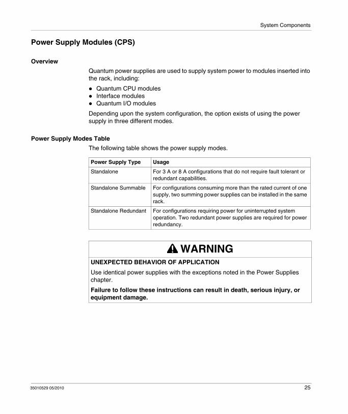
Power Supply Modes Table
The following table shows the power supply modes.
Power Supply Type Usage
Standalone For 3 A or 8 A configurations that do not require fault tolerant or redundant capabilities.
Standalone Summable For configurations consuming more than the rated current of one supply, two summing power supplies can be installed in the same rack.
Standalone Redundant For configurations requiring power for uninterrupted system operation. Two redundant power supplies are required for power redundancy.
WARNINGUNEXPECTED BEHAVIOR OF APPLICATION
Use identical power supplies with the exceptions noted in the Power Supplies chapter.
Failure to follow these instructions can result in death, serious injury, or equipment damage.
35010529 05/2010 25
System Components
I/O Modules
Overview
Quantum I/O modules are electrical signal converters that convert signals to and from field devices to a signal level and format that can be processed by the CPU.
I/O modules are optically isolated to the bus. I/O modules are also software configurable.
Field Devices
Typical field devices include:
limit switchesproximity switchestemperature sensorssolenoidsvalve actuators
Further Information
NOTE: For detailed information see in the Quantum I/O Hardware Guide:
Quantum I/O Analog IN Modules (see Quantum with Unity Pro, Discrete and Analog I/O, Reference Manual)Quantum I/O Analog OUT Modules (see Quantum with Unity Pro, Discrete and Analog I/O, Reference Manual)Quantum I/O Analog IN / OUT Modules (see Quantum with Unity Pro, Discrete and Analog I/O, Reference Manual)Quantum I/O Discrete IN Modules (see Quantum with Unity Pro, Discrete and Analog I/O, Reference Manual)Quantum I/O Discrete OUT Modules (see Quantum with Unity Pro, Discrete and Analog I/O, Reference Manual)Quantum I/O Discrete IN / OUT Modules (see Quantum with Unity Pro, Discrete and Analog I/O, Reference Manual)Quantum Intrinsically Safe Analog/Digital Modules (see Quantum with Unity Pro, Discrete and Analog I/O, Reference Manual)Quantum Safety I/O Modules (see Quantum with Unity Pro, Discrete and Analog I/O, Reference Manual)
26 35010529 05/2010
System Components
Network Interface Modules
Overview
Different types of network interface modules are available and presented in the table below with their descriptions.
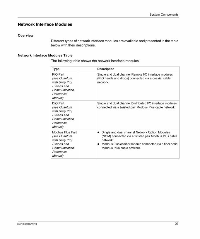
Network Interface Modules Table
The following table shows the network interface modules.
Type Description
RIO Part (see Quantum with Unity Pro, Experts and Communication, Reference Manual)
Single and dual channel Remote I/O interface modules (RIO heads and drops) connected via a coaxial cable network.
DIO Part (see Quantum with Unity Pro, Experts and Communication, Reference Manual)
Single and dual channel Distributed I/O interface modules connected via a twisted pair Modbus Plus cable network.
Modbus Plus Part (see Quantum with Unity Pro, Experts and Communication, Reference Manual)
Single and dual channel Network Option Modules (NOM) connected via a twisted pair Modbus Plus cable network.Modbus Plus on fiber module connected via a fiber optic Modbus Plus cable network.
35010529 05/2010 27

System Components
Ethernet Module (see Quantum with Unity Pro, Experts and Communication, Reference Manual)
TCP/IP Single channel TCP/IP Ethernet interface module connected via a twisted pair or fiber optic cable network.
SY/MAX SY/MAX Ethernet module connected via a twisted pair or fiber optic cable network.
Field Bus Part (see Quantum with Unity Pro, Experts and Communication, Reference Manual)
Lonworks Lonworks module connected via a twisted-pair network.
Interbus Interbus Interface module connected via a twisted pair network.
Profibus Profibus interface module connected via a Profibus port
AS-i The Quantum AS-i Master Module provides AS-i communications between the bus master module and the sensor/actuator slaves.
Sercos The SERCOS® Multi-Motion modules (MMS) are used to build a distributed automation solution, integrating motion applications with control applications
Type Description
28 35010529 05/2010
System Components
Intelligent/Special Purpose I/O Modules
Overview
Quantum Intelligent/Special Purpose I/O modules operate with minimum intervention from the Quantum controller after initial downloading of module parameters or programs. The Quantum intelligent/special purpose I/O modules include the following:
High Speed Counter modules (EHC)ASCII Interface module (ESI)High Speed Interrupt module (HLI)Time Stamp modules (ERT)Clock module (DCF)
35010529 05/2010 29
System Components
Simulator (XSM) and Battery (XCP) Module
Overview
There are two types of simulator modules, as described below.
Discrete and Analog Simulators Table
The following table shows discrete and analog simulators.
Battery Module (XCP)
The Quantum battery module provides RAM backup power for Quantum expert modules.
Further Information
For detailed information see Simulator (XSM) and Battery (XCP) Module, page 291.
Simulator Points / Channels
Type Description
Discrete Simulator
16 Points IN 140 XSM 002 00 is used to generate up to 16 binary input signals to the 140 DAI 540 00 and the 140 DAI 740 00 AC input modules.
Analog Simulator
2 channels IN1 channel OUT
140 XSM 010 00 is used for simulating 4 ... 20 mA field current loops used with current input Quantum modules.
30 35010529 05/2010

System Components
Racks (XBP) and Rack Expander (XBE)
Racks (XBP)
Quantum racks may be used in any locations of local, remote, or distributed I/O. There are six racks available in 2, 3, 4, 6, 10, and 16 slot versions.
Rack Expander (XBE)
The 140 XBE 100 00 Rack Expander provides the Modicon Quantum with the capacity to expand Local and Remote I/O drops to a second rack. For improved I/O capacity and efficiency, the rack expander will save money by minimizing the number of Remote I/O drops. The Rack Expander also improves the overall performance of Remote I/O based systems by reducing the number of Remote I/O drops the Quantum CPU has to service. The Rack Expander effectively doubles the maximum number of Discrete I/O that can be serviced by a Quantum Remote I/O system.
Further Information
NOTE: For detailed information see Racks(XBP) and Rack Expander (XBE), page 273
35010529 05/2010 31
System Components
CableFast Cabling (CFx) for I/O Modules
Overview
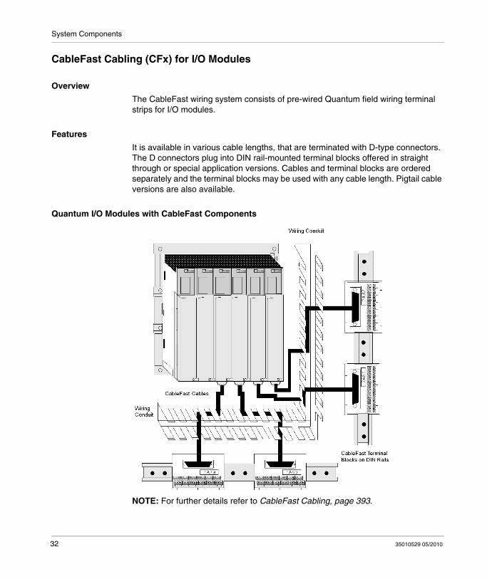
The CableFast wiring system consists of pre-wired Quantum field wiring terminal strips for I/O modules.
Features
It is available in various cable lengths, that are terminated with D-type connectors. The D connectors plug into DIN rail-mounted terminal blocks offered in straight through or special application versions. Cables and terminal blocks are ordered separately and the terminal blocks may be used with any cable length. Pigtail cable versions are also available.
Quantum I/O Modules with CableFast Components
NOTE: For further details refer to CableFast Cabling, page 393.
32 35010529 05/2010
System Components
Hot Standby System
Function
A Hot Standby (HSBY) system is based on two identically configured programmable logic controllers linked to each other and to the same remote I/O network. If one controller stops, the other assumes control of the I/O system.
Primary and Standby Controller
The Quantum Hot Standby system is designed for use where downtime cannot be tolerated. The system delivers high availability through redundancy. Two racks are configured with identical hardware and software. One of the PLCs acts as the primary controller. It runs the application by scanning user logic and operating remote I/O. The other PLC acts as the standby controller. The primary controller updates the standby controller after each scan. The standby is ready to assume control within one scan if the primary stops. Primary and standby states are switchable. Either controller can be put into the primary state, but to do this, the other must be in the standby state. The remote I/O network is operated by the primary controller.
NOTE: A Quantum Hot Standby system supports only remote I/O. It does not support local I/O or distributed I/O (DIO).
For a detailed description of the Hot Standby (HSBY) system refer to the HSBY User guide , page
35010529 05/2010 33

System Components
34 35010529 05/2010
35010529 05/2010
3
Network Support
35010529 05/2010
Network Support
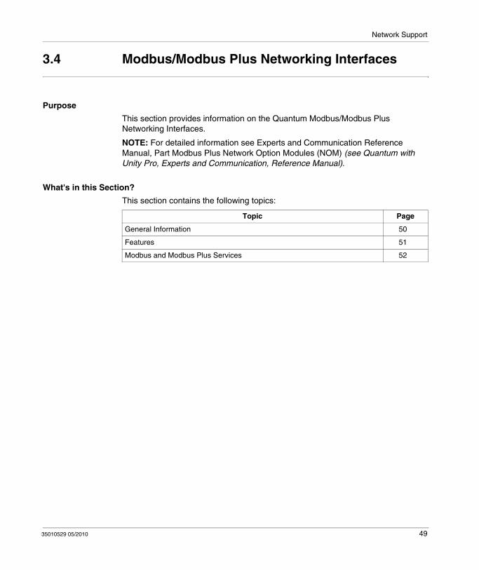
Purpose
This chapter provides an overview of the Quantum Network Support.
What's in this Chapter?
This chapter contains the following sections:
Section Topic Page
3.1 General Information 36
3.2 Remote I/O (RIO) and Distributed I/O (DIO) 41
3.3 Ethernet Networking Interfaces 46
3.4 Modbus/Modbus Plus Networking Interfaces 49
3.5 Fieldbus Networking Interfaces 53
35
Network Support
3.1 General Information
Purpose
This section provides general information on the Quantum Network Support.
What's in this Section?
This section contains the following topics:
Topic Page
Supported Networks Table 37
Quantum Network Interface Techniques 39
36 35010529 05/2010
Network Support
Supported Networks Table
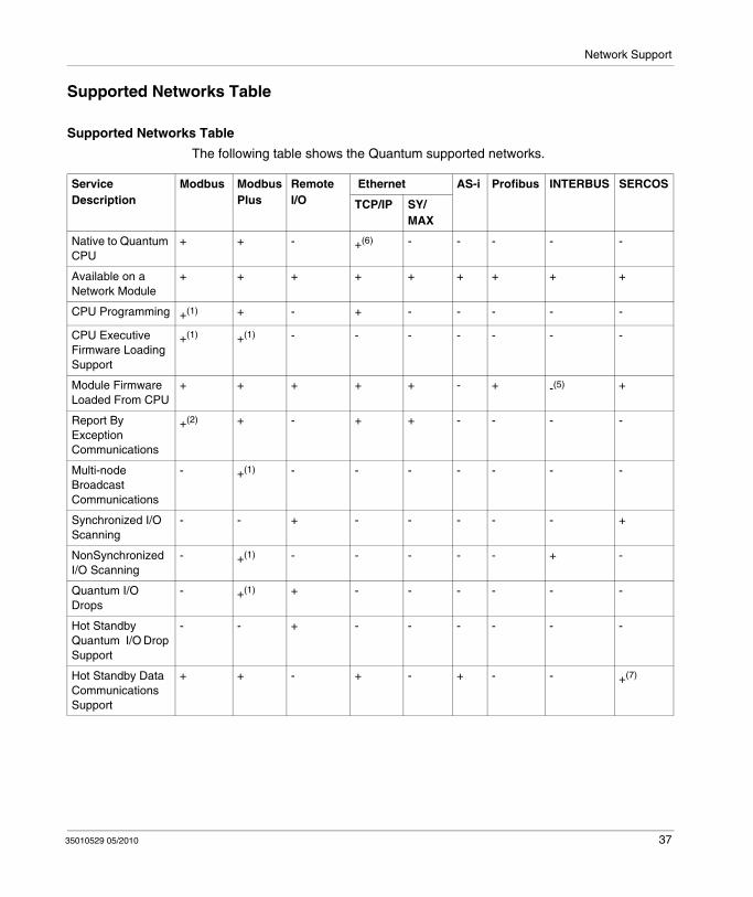
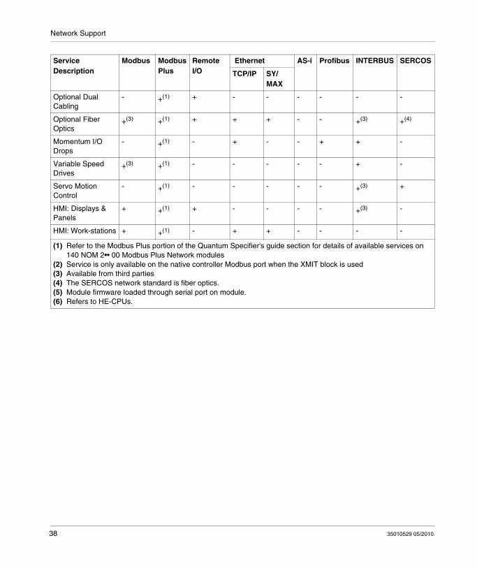
Supported Networks Table
The following table shows the Quantum supported networks.
Service Description
Modbus Modbus Plus
Remote I/O
Ethernet AS-i Profibus INTERBUS SERCOS
TCP/IP SY/ MAX
Native to Quantum CPU
+ + - +(6) - - - - -
Available on a Network Module
+ + + + + + + + +
CPU Programming +(1) + - + - - - - -
CPU Executive Firmware Loading Support
+(1) +(1) - - - - - - -
Module Firmware Loaded From CPU
+ + + + + - + -(5) +
Report By Exception Communications
+(2) + - + + - - - -
Multi-node Broadcast Communications
- +(1) - - - - - - -
Synchronized I/O Scanning
- - + - - - - - +
NonSynchronized I/O Scanning
- +(1) - - - - - + -
Quantum I/O Drops
- +(1) + - - - - - -
Hot Standby Quantum I/O Drop Support
- - + - - - - - -
Hot Standby Data Communications Support
+ + - + - + - - +(7)
35010529 05/2010 37
Network Support
Optional Dual Cabling
- +(1) + - - - - - -
Optional Fiber Optics
+(3) +(1) + + + - - +(3) +(4)
Momentum I/O Drops
- +(1) - + - - + + -
Variable Speed Drives
+(3) +(1) - - - - - + -
Servo Motion Control
- +(1) - - - - - +(3) +
HMI: Displays & Panels
+ +(1) + - - - - +(3) -
HMI: Work-stations + +(1) - + + - - - -
(1) Refer to the Modbus Plus portion of the Quantum Specifier's guide section for details of available services on 140 NOM 2•• 00 Modbus Plus Network modules
(2) Service is only available on the native controller Modbus port when the XMIT block is used(3) Available from third parties(4) The SERCOS network standard is fiber optics.(5) Module firmware loaded through serial port on module.(6) Refers to HE-CPUs.
Service Description
Modbus Modbus Plus
Remote I/O
Ethernet AS-i Profibus INTERBUS SERCOS
TCP/IP SY/ MAX
38 35010529 05/2010
Network Support
Quantum Network Interface Techniques
Overview
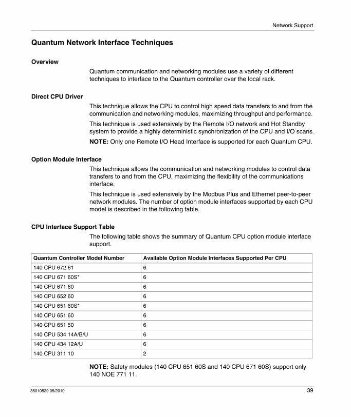
Quantum communication and networking modules use a variety of different techniques to interface to the Quantum controller over the local rack.
Direct CPU Driver
This technique allows the CPU to control high speed data transfers to and from the communication and networking modules, maximizing throughput and performance.
This technique is used extensively by the Remote I/O network and Hot Standby system to provide a highly deterministic synchronization of the CPU and I/O scans.
NOTE: Only one Remote I/O Head Interface is supported for each Quantum CPU.
Option Module Interface
This technique allows the communication and networking modules to control data transfers to and from the CPU, maximizing the flexibility of the communications interface.
This technique is used extensively by the Modbus Plus and Ethernet peer-to-peer network modules. The number of option module interfaces supported by each CPU model is described in the following table.
CPU Interface Support Table
The following table shows the summary of Quantum CPU option module interface support.
NOTE: Safety modules (140 CPU 651 60S and 140 CPU 671 60S) support only 140 NOE 771 11.
Quantum Controller Model Number Available Option Module Interfaces Supported Per CPU
140 CPU 672 61 6
140 CPU 671 60S* 6
140 CPU 671 60 6
140 CPU 652 60 6
140 CPU 651 60S* 6
140 CPU 651 60 6
140 CPU 651 50 6
140 CPU 534 14A/B/U 6
140 CPU 434 12A/U 6
140 CPU 311 10 2
35010529 05/2010 39

Network Support
Communications and Networking Table
The following table shows the Quantum communications and networking modules.
Model Number Description Module Interface Technique
Rack Support Bus Power mALocal RIO DIO
140 CRP 931 00 Remote I/O Head Interface, single cable
Direct CPU Driver Y N N 780
140 CRP 932 00 Remote I/O Head Interface, dual cable
Direct CPU Driver Y N N 780
140 NOM 211 00 Modbus Plus Options, single cable
Option Module Y N N 780
140 NOM 212 00 Modbus Plus Option, dual cable
Option Module Y N N 780
140 NOM 252 00 Modbus Plus Option, single channel fiber
Option Module Y N N 900
140 NOE 211 00 Ethernet TCP/IP Twisted Pair Option Module Y N N 1000
140 NOE 251 00 Ethernet TCP/IP Fiber Optic Option Module Y N N 1000
140 NOE 311 00 One 10BASE-T Ethernet/ SY/MAX (RJ45) port.
Option Module Y N N 1000
140 NOE 351 00 Two 10BASE-T Ethernet/ SY/MAX (RJ45) port.
Option Module Y N N 1000
140 NOE 771 •• Ethernet TCP/IP Twisted Pair/Fiber Optic
Option Module Y N N 750
140 EIA 921 00 AS-i Master I/O Map (13/9) Y Y Y 250
140 MMS 425 00 Multi-Axis Motion Controller w/SERCOS
Option Module Y N N 2500
PTQ PDP MV1 Profibus Option Module Option Module Y N N 1200
40 35010529 05/2010

Network Support
3.2 Remote I/O (RIO) and Distributed I/O (DIO)
Purpose
This section provides information on the Quantum (RIO) and (DIO).
What's in this Section?
This section contains the following topics:
Topic Page
Remote I/O (RIO) 42
Execution of Quantum Sections with Remote Inputs/Outputs 43
Distributed I/O (DIO) 45
35010529 05/2010 41
Network Support
Remote I/O (RIO)
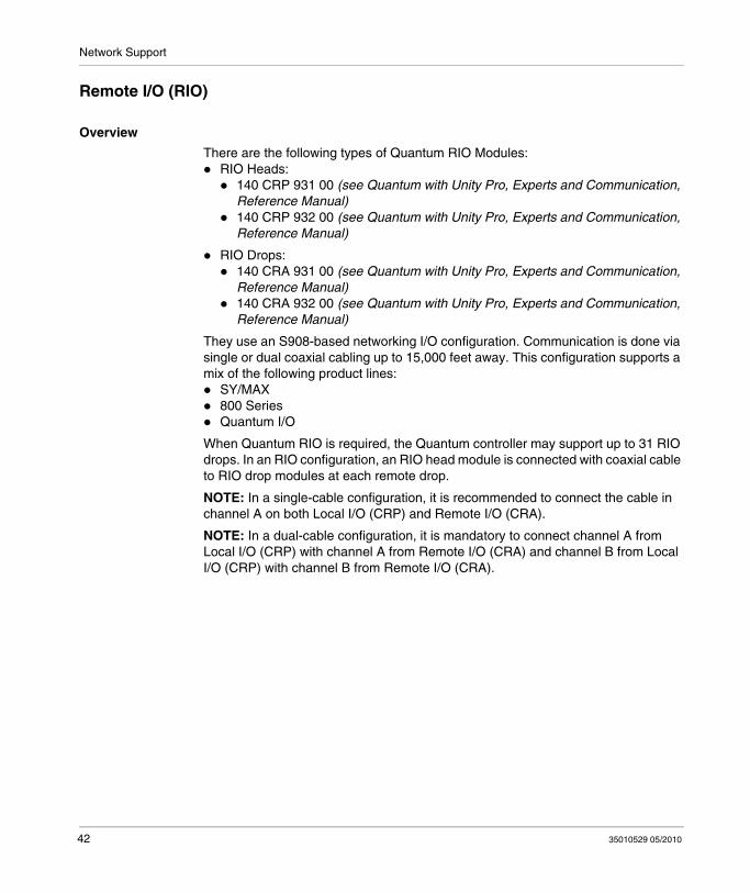
Overview
There are the following types of Quantum RIO Modules: RIO Heads:
140 CRP 931 00 (see Quantum with Unity Pro, Experts and Communication, Reference Manual)140 CRP 932 00 (see Quantum with Unity Pro, Experts and Communication, Reference Manual)
RIO Drops:140 CRA 931 00 (see Quantum with Unity Pro, Experts and Communication, Reference Manual)140 CRA 932 00 (see Quantum with Unity Pro, Experts and Communication, Reference Manual)
They use an S908-based networking I/O configuration. Communication is done via single or dual coaxial cabling up to 15,000 feet away. This configuration supports a mix of the following product lines:
SY/MAX800 SeriesQuantum I/O
When Quantum RIO is required, the Quantum controller may support up to 31 RIO drops. In an RIO configuration, an RIO head module is connected with coaxial cable to RIO drop modules at each remote drop.
NOTE: In a single-cable configuration, it is recommended to connect the cable in channel A on both Local I/O (CRP) and Remote I/O (CRA).
NOTE: In a dual-cable configuration, it is mandatory to connect channel A from Local I/O (CRP) with channel A from Remote I/O (CRA) and channel B from Local I/O (CRP) with channel B from Remote I/O (CRA).
42 35010529 05/2010

Network Support
Execution of Quantum Sections with Remote Inputs/Outputs
General
Quantum PLCs have a specific section management system. It applies to stations with remote inputs/outputs.
These stations are used with following RIO modules:140 CRA 931 00140 CRA 932 00
This system allows remote inputs/outputs to be updated on sections with optimum response times (without waiting for the entire task cycle before updating the inputs/outputs).
Operation
The following diagram shows the IO phases when 5 drops are associated to client task sections.
%Ii inputs of drop No. i%Qi outputs of drop No. ii drop number
35010529 05/2010 43
Network Support
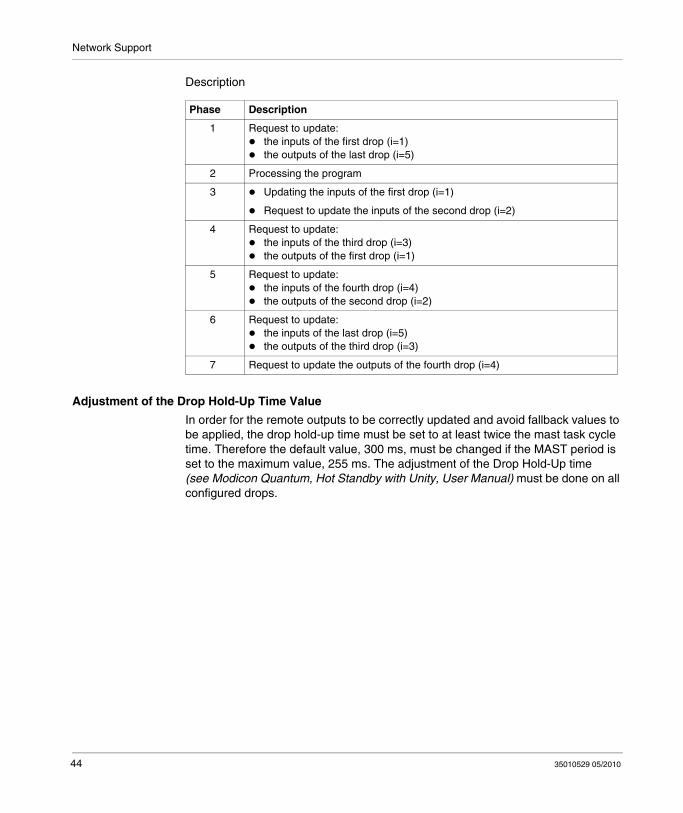
Description
Adjustment of the Drop Hold-Up Time Value
In order for the remote outputs to be correctly updated and avoid fallback values to be applied, the drop hold-up time must be set to at least twice the mast task cycle time. Therefore the default value, 300 ms, must be changed if the MAST period is set to the maximum value, 255 ms. The adjustment of the Drop Hold-Up time (see Modicon Quantum, Hot Standby with Unity, User Manual) must be done on all configured drops.
Phase Description
1 Request to update:the inputs of the first drop (i=1)the outputs of the last drop (i=5)
2 Processing the program
3 Updating the inputs of the first drop (i=1)
Request to update the inputs of the second drop (i=2)
4 Request to update:the inputs of the third drop (i=3)the outputs of the first drop (i=1)
5 Request to update:the inputs of the fourth drop (i=4)the outputs of the second drop (i=2)
6 Request to update:the inputs of the last drop (i=5)the outputs of the third drop (i=3)
7 Request to update the outputs of the fourth drop (i=4)
44 35010529 05/2010

Network Support
Distributed I/O (DIO)
Overview
Quantum DIO is implemented over a Modbus Plus network. The CPU or NOM modules may be the network head via their Modbus Plus ports.
Quantum DIO Modbus Plus drop adaptors are specifically designed to link Quantum I/O modules to the head via twisted pair shielded cable (Modbus Plus). The DIO drop modules also provide the I/O with power (maximum 3 A) from a 24 VDC or a 115/230 VAC source. Each DIO network supports up to 63 distributed drops using repeaters.
NOTE: For detailed information see Experts and Communication Reference Manual, Part Quantum Distributed I/O (DIO) Drop Modules (see Quantum with Unity Pro, Experts and Communication, Reference Manual).
35010529 05/2010 45
Network Support
3.3 Ethernet Networking Interfaces
Purpose
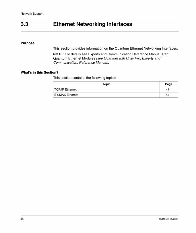
This section provides information on the Quantum Ethernet Networking Interfaces.
NOTE: For details see Experts and Communication Reference Manual, Part Quantum Ethernet Modules (see Quantum with Unity Pro, Experts and Communication, Reference Manual).
What's in this Section?
This section contains the following topics:
Topic Page
TCP/IP Ethernet 47
SY/MAX Ethernet 48
46 35010529 05/2010

Network Support
TCP/IP Ethernet
Overview
Quantum TCP/IP Ethernet modules make it possible for a Quantum controller to communicate with devices on an Ethernet network using TCP/IP – the de facto standard protocol. An Ethernet module may be inserted into an existing Quantum system and connected to existing Ethernet networks via fiber optic or twisted pair cabling.
35010529 05/2010 47

Network Support
SY/MAX Ethernet
Overview
Quantum-SY/MAX Ethernet modules are Quantum modules that can be placed in a Quantum rack, to connect Quantum controllers to SY/MAX devices and applications.
48 35010529 05/2010
Network Support
3.4 Modbus/Modbus Plus Networking Interfaces
Purpose
This section provides information on the Quantum Modbus/Modbus Plus Networking Interfaces.
NOTE: For detailed information see Experts and Communication Reference Manual, Part Modbus Plus Network Option Modules (NOM) (see Quantum with Unity Pro, Experts and Communication, Reference Manual).
What's in this Section?
This section contains the following topics:
Topic Page
General Information 50
Features 51
Modbus and Modbus Plus Services 52
35010529 05/2010 49

Network Support
General Information
Overview
Quantum NOM modules provide extended communication capabilities for the Quantum system within a Modbus and a Modbus Plus configuration.
Modbus
Modbus, a master/slave protocol, is a de facto industry standard with support from over 500 industrial suppliers.
On-line programming or data acquisition applications are easily supported directly from the serial port of any computer.
Modbus can be used in either a simple point-to-point manner with a pair of devices, or in a network architecture with up to 247 slave devices.
Modbus Plus
Modbus Plus combines high speed, peer-to-peer communication and easy installation to simplify applications and reduce installation costs.
It allows host computers, controllers and other data sources to communicate as peers throughout the network via low-cost twisted pair cable or optional fiber optic cable.
As a deterministic token-passing network, Modbus Plus communicates at one megabaud for fast access to process data. It’s strength is its ability to control real-time control devices like I/O and drives, without degraded performance due to loading or traffic.
Bridging between Modbus and Modbus Plus is done automatically on CPUs and Modbus Plus network modules.
The bridge mode redirects Modbus messages onto the Modbus Plus network for easy connectivity between Modbus and Modbus Plus devices.
A summary of the available services on Quantum Modbus and Modbus Plus ports is given in the following table.
Modbus Plus on Fiber Module
Quantum Modbus Plus on Fiber modules provides connectivity to Modbus Plus nodes by fiber cable without fiber optic repeaters.
The use of a 490 NRP 254 Fiber Optic Repeater allows the creation of a pure fiber optic network or a mixed fiber optic/twisted-pair network.
50 35010529 05/2010
Network Support
Features
Overview
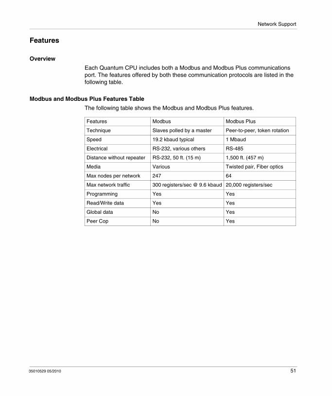
Each Quantum CPU includes both a Modbus and Modbus Plus communications port. The features offered by both these communication protocols are listed in the following table.
Modbus and Modbus Plus Features Table
The following table shows the Modbus and Modbus Plus features.
Features Modbus Modbus Plus
Technique Slaves polled by a master Peer-to-peer, token rotation
Speed 19.2 kbaud typical 1 Mbaud
Electrical RS-232, various others RS-485
Distance without repeater RS-232, 50 ft. (15 m) 1,500 ft. (457 m)
Media Various Twisted pair, Fiber optics
Max nodes per network 247 64
Max network traffic 300 registers/sec @ 9.6 kbaud 20,000 registers/sec
Programming Yes Yes
Read/Write data Yes Yes
Global data No Yes
Peer Cop No Yes
35010529 05/2010 51

Network Support
Modbus and Modbus Plus Services
Modbus and Modbus Plus Services Table
The following table shows the Quantum Modbus and Modbus Plus services.
Type Service Description Native CPU Ports NOM 1-2 Ports NOM 3-6 Ports1
Modbus Modbus Plus
Modbus Modbus Plus
Modbus Modbus Plus
Modbus Services
Default Modbus Port Parameters Yes - Yes - Yes -
Configurable Modbus Port Parameters Yes - Yes - Yes(5) -
Modbus to Modbus Plus Bridging Yes(1) - Yes(2) - Yes(2) -
Local CPU Programming Yes(3) - Yes(3) - No -
Remote CPU Programming over Modbus Plus
Yes(3) - Yes(3) - Yes(1) -
Modbus access to local CPU Yes - Yes - No -
Modbus access to remote CPU over Modbus Plus
Yes - Yes - Yes -
Modbus Network Slave Support Yes - No - No -
Modbus Master support with XMIT block Yes - No - No -
Executive Firmware Loading Support Yes - No - No -
Modbus Plus services
MSTR read/write register messaging(4) - Yes - Yes - Yes
MSTR read/write Global Data messaging
- Yes - Yes - Yes
MSTR get/clear local/remote statistics - Yes - Yes - Yes
Config Extension Global Data Support - Yes - Yes - No
Config Extension Peer Cop Support - Yes - Yes - No
Distributed I/O Support - Yes - Yes - No
CPU Programming - Yes(3) - Yes(3) - Yes(3)
Executive Firmware Loading Support - Yes - No - No
(1) The native CPU Modbus port can be disabled from bridge mode operation with the native Modbus Plus Port.(2) Modbus ports on NOMs are in bridge mode with their associated Modbus Plus port.(3) Only one programmer connection can be logged in at a time to any CPU, and only one program monitor can be
attached at a time to any CPU.(4) Up to 4 MSTR read/write register instructions can be serviced per CPU scan per Modbus Plus port.(5) Modbus port parameters on NOMs 3-6 are defined by Modbus Port 3 when the comm parameter selector switch
is in mem.
52 35010529 05/2010
Network Support
3.5 Fieldbus Networking Interfaces
Purpose
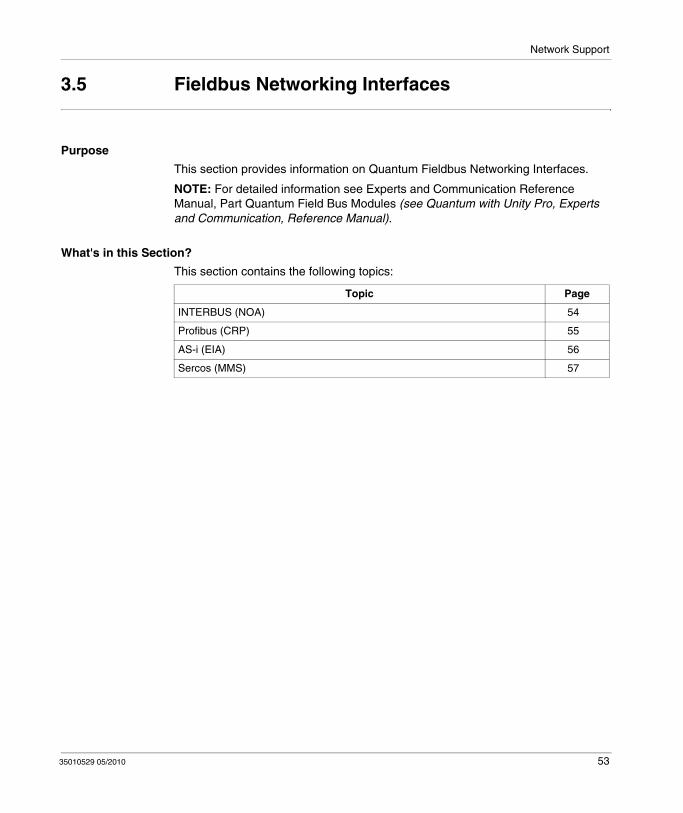
This section provides information on Quantum Fieldbus Networking Interfaces.
NOTE: For detailed information see Experts and Communication Reference Manual, Part Quantum Field Bus Modules (see Quantum with Unity Pro, Experts and Communication, Reference Manual).
What's in this Section?
This section contains the following topics:
Topic Page
INTERBUS (NOA) 54
Profibus (CRP) 55
AS-i (EIA) 56
Sercos (MMS) 57
35010529 05/2010 53

Network Support
INTERBUS (NOA)
Overview
Quantum INTERBUS (NOA) modules provide connectivity between a Quantum controller and the INTERBUS network.
The INTERBUS is a fieldbus network designed for I/O blocks and intelligent devices used in manufacturing. It offers a master/slave topology which permits deterministic I/O servicing over its network which can be up to 12.8 km (8 miles) in length..
54 35010529 05/2010
Network Support
Profibus (CRP)
Overview
The PTQ PDP MV1 Profibus DP Communication Module provides connectivity to the Profibus.
Profibus DP is a fieldbus designed for I/O communication used in manufacturing. It supports baudrates up to 12 MBaud.
35010529 05/2010 55
Network Support
AS-i (EIA)
Overview
The Quantum AS-i Master Module provides AS-i communications between the bus master module and the sensor/actuator slaves. One master module can control 31 slaves. Multiple master modules can be used in a single control system. These sensor/actuators can be in the local CPU, an RIO, or a DIO drop adapter.
56 35010529 05/2010
Network Support
Sercos (MMS)
Overview
The SERCOS® MMS motion modules are used to build a distributed automation solution, integrating motion applications with control applications, based on Quantum PLCs. The axis modules and Quantum CPUs communicate either through the Quantum rack or by using the Modbus Plus network. The data transfer is transparent, and does not need any additional application program.
Fiber optic interface
The physical interface between the SERCOS module and the servo drive is done by the SERCOS network, using fiber optic cable. This optic link is entirely digital, and provides communication parameters for the tuning, diagnostics, and operation of both motion control modules and servo drives.
35010529 05/2010 57

Network Support
58 35010529 05/2010

35010529 05/2010
4
Quantum Configurations
35010529 05/2010
Quantum Configurations
Purpose
This chapter provides information on the Quantum Configurations.
What's in this Chapter?
This chapter contains the following sections:
Section Topic Page
4.1 Quantum Local I/O, Remote I/O and Distributed I/O 60
4.2 Quantum Local I/O 63
4.3 Quantum Remote I/O (RIO) 66
4.4 Quantum Distributed I/O (DIO) 69
59
Quantum Configurations
4.1 Quantum Local I/O, Remote I/O and Distributed I/O
Purpose
This section provides information on the features and configuration of Quantum Local I/O, Remote I/O and Distributed I/O.
What's in this Section?
This section contains the following topics:
Topic Page
Features 61
Local, RIO and DIO Configuration 62
60 35010529 05/2010

Quantum Configurations
Features
Local, Remote and Distributed I/O Features
The following table shows features of the Local, Remote and Distributed I/O configurations.
Feature Configuration
Local I/O Remote I/O Distributed I/O
Maximum I/O Words
Per drop unlimited I/O 64 IN / 64 OUT 30 IN / 32 OUT
Per network 1,984 IN / 1,984 OUT 500 IN / 500 OUT
Maximum drops per network
31 63 (with repeater)
Media Coax Twisted Pair
Speed 1.5 MHz 1 MHz
Maximum distance without repeaters
15,000 ft. (4,573 m) 1,500 ft. (457 m)
Scan synched I/O servicing
Yes No
Momentum I/O support
No Yes
Hot Standby support
Yes No
Modbus Plus compatible
No Yes
35010529 05/2010 61
Quantum Configurations
Local, RIO and DIO Configuration
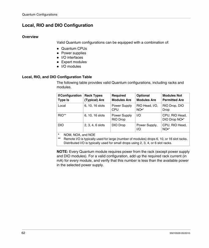
Overview
Valid Quantum configurations can be equipped with a combination of:
Quantum CPUsPower suppliesI/O interfacesExpert modulesI/O modules
Local, RIO, and DIO Configuration Table
The following table provides valid Quantum configurations, including racks and modules.
NOTE: Every Quantum module requires power from the rack (except power supply and DIO modules). For a valid configuration, add up the required rack current (in mA) for every module, and verify that this number is less than the available power in the selected power supply.
If Configuration Type Is
Rack Types (Typical) Are
Required Modules Are
Optional Modules Are
Modules Not Permitted Are
Local 6, 10, 16 slots Power Supply CPU
RIO Head, I/O, NO•*
RIO Drop, DIO Drop
RIO** 6, 10, 16 slots Power Supply RIO Drop
I/O CPU, RIO Head, DIO Drop NO•*
DIO 2, 3, 4, 6 slots DIO Drop Power Supply, I/O
CPU, RIO Head, NO•*
* NOM, NOA, and NOE** Remote I/O is typically used for large (number of modules) drops 6, 10, or 16 slot racks.
Distributed I/O is typically used for small drops using 2, 3, 4, or 6 slot racks.
62 35010529 05/2010

Quantum Configurations
4.2 Quantum Local I/O
Purpose
This chapter provides an Overview on the Quantum Local I/O.
What's in this Section?
This section contains the following topics:
Topic Page
Configuration 64
Example 65
35010529 05/2010 63
Quantum Configurations
Configuration
Overview
A local I/O configuration is contained in one to two racks and includes Quantum modules mounted in a standard Quantum rack. Quantum Local I/O can be as few as one I/O module (in a three slot rack).
Or a maximum of 27 I/Os totalized as follows:13 in the first rack along with CPU, power supply and expansion module (XBE) 14 in the expansion rack along with power supply and expansion module (XBE)
64 35010529 05/2010

Quantum Configurations
Example
I/O Configuration Figure
The following figure is an example of a typical local I/O configuration.
35010529 05/2010 65

Quantum Configurations
4.3 Quantum Remote I/O (RIO)
Purpose
This section provides an overview on the configuration of the Quantum Remote I/O (RIO).
NOTE: For detailed information see Experts and Communication Reference Manual, Part Quantum Remote I/O (RIO) Modules (see Quantum with Unity Pro, Experts and Communication, Reference Manual).
What's in this Section?
This section contains the following topics:
Topic Page
Single-cable Configuration 67
Dual-cable Configuration 68
66 35010529 05/2010

Quantum Configurations
Single-cable Configuration
Single-cable RIO Configuration Figure
The following figure is an example of a single-cable Quantum RIO configuration.
NOTE: In a single-cable configuration, it is recommended to connect the cable in channel A on both Local I/O (CRP) and Remote I/O (CRA).
35010529 05/2010 67
Quantum Configurations
Dual-cable Configuration
Dual-cable RIO Configuration Figure
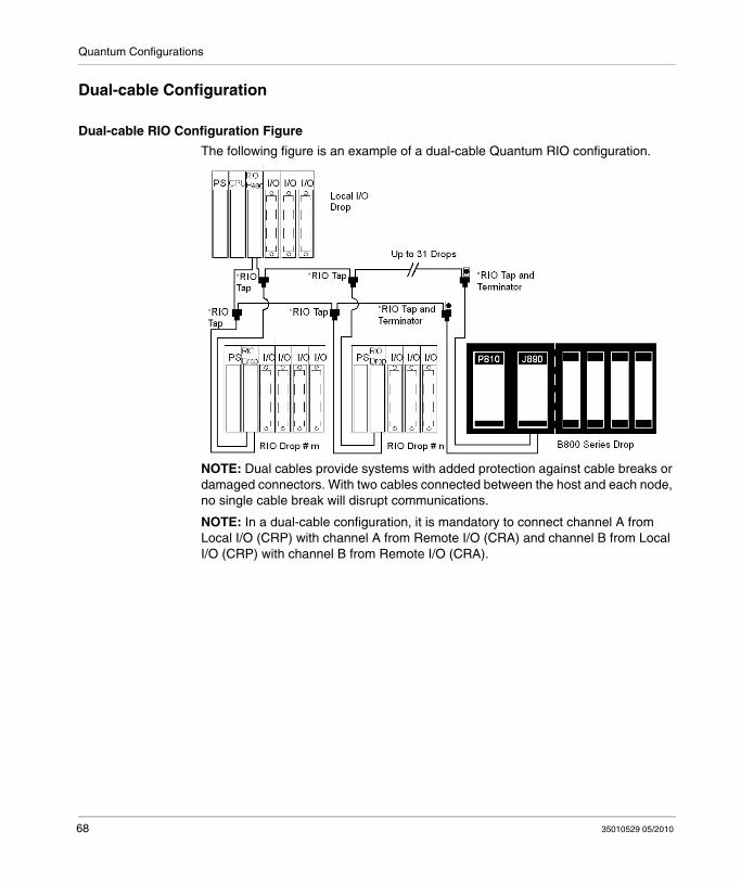
The following figure is an example of a dual-cable Quantum RIO configuration.
NOTE: Dual cables provide systems with added protection against cable breaks or damaged connectors. With two cables connected between the host and each node, no single cable break will disrupt communications.
NOTE: In a dual-cable configuration, it is mandatory to connect channel A from Local I/O (CRP) with channel A from Remote I/O (CRA) and channel B from Local I/O (CRP) with channel B from Remote I/O (CRA).
68 35010529 05/2010
Quantum Configurations
4.4 Quantum Distributed I/O (DIO)
Purpose
This section provides an overview on the configuration of Quantum Distributed I/O (DIO).
NOTE: For detailed information see Experts and Communication Reference Manual, Part III Quantum Distributed I/O (DIO) Drop Modules (see Quantum with Unity Pro, Experts and Communication, Reference Manual).
What's in this Section?
This section contains the following topics:
Topic Page
Single-cable Configuration 70
Dual-cable Configuration 71
35010529 05/2010 69
Quantum Configurations
Single-cable Configuration
Single-cable DIO Configuration Figure
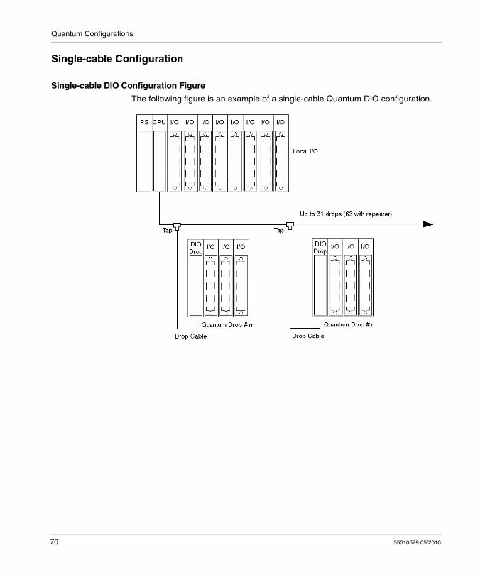
The following figure is an example of a single-cable Quantum DIO configuration.
70 35010529 05/2010

Quantum Configurations
Dual-cable Configuration
Dual-cable DIO Configuration Figure
The following figure is an example of a dual-cable Quantum DIO configuration.
NOTE: Dual cables provide systems with added protection against cable breaks or damaged connectors. With two cables connected between the host and each node, no single cable break will disrupt communications.
35010529 05/2010 71

Quantum Configurations
72 35010529 05/2010

35010529 05/2010
5
Module Configuration
35010529 05/2010
Module Configuration
Purpose
This chapter provides information on software configuration of the module.
What's in this Chapter?
This chapter contains the following topics:
Topic Page
Mapping a Local Quantum I/O Station 74
Open the Parameter Configuration 75
73
Module Configuration
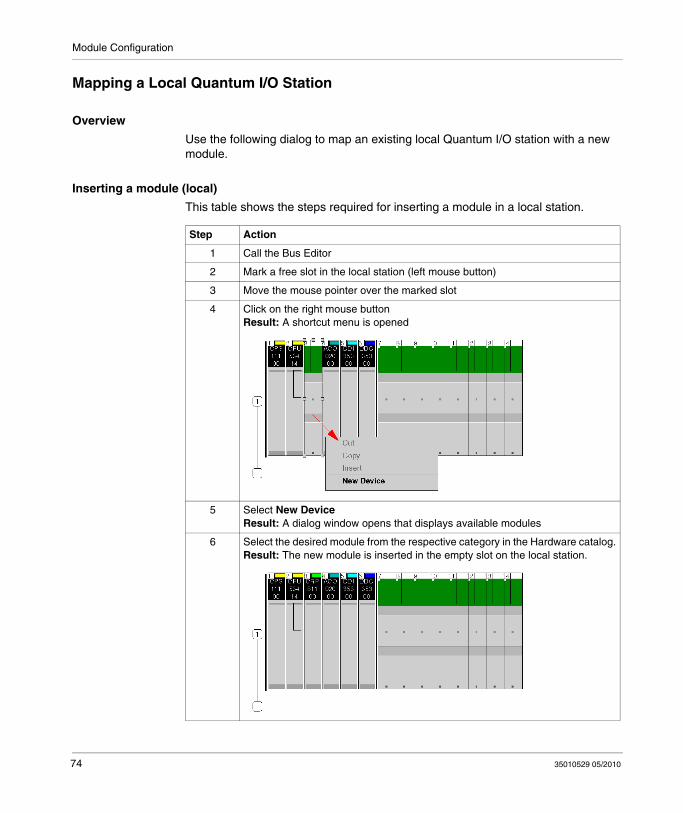
Mapping a Local Quantum I/O Station
Overview
Use the following dialog to map an existing local Quantum I/O station with a new module.
Inserting a module (local)
This table shows the steps required for inserting a module in a local station.
Step Action
1 Call the Bus Editor
2 Mark a free slot in the local station (left mouse button)
3 Move the mouse pointer over the marked slot
4 Click on the right mouse buttonResult: A shortcut menu is opened
5 Select New DeviceResult: A dialog window opens that displays available modules
6 Select the desired module from the respective category in the Hardware catalog.Result: The new module is inserted in the empty slot on the local station.
74 35010529 05/2010
Module Configuration
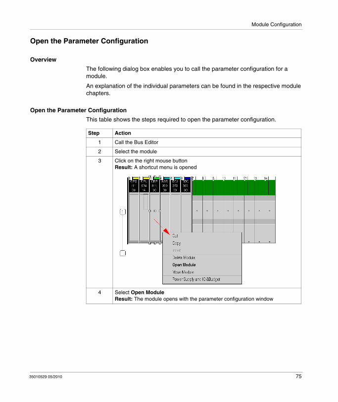
Open the Parameter Configuration
Overview
The following dialog box enables you to call the parameter configuration for a module.
An explanation of the individual parameters can be found in the respective module chapters.
Open the Parameter Configuration
This table shows the steps required to open the parameter configuration.
Step Action
1 Call the Bus Editor
2 Select the module
3 Click on the right mouse buttonResult: A shortcut menu is opened
4 Select Open ModuleResult: The module opens with the parameter configuration window
35010529 05/2010 75

Module Configuration
76 35010529 05/2010

35010529 05/2010
6
Installation
35010529 05/2010
Hardware Installation and Maintenance
Purpose
This chapter provides information on the Quantum hardware installation and maintenance.
What's in this Chapter?
This chapter contains the following topics:
Topic Page
Space Requirements 78
Mounting Brackets 80
Mounting Quantum Modules 82
Mounting and Removing a Terminal Strip 86
Mounting Jumper Clips 88
Removing a Module Door 89
77

Installation
Space Requirements
Spacing Requirements Figure
The following figure shows the Quantum system spacing requirements.
78 35010529 05/2010
Installation
Spacing Requirements Table
The following table gives a summary of the spacing requirements for a Quantum system.
Minimum Spacing Location
4 in. (101.60 mm) Between the top of the cabinet and the top of the modules in the upper rack.
4 in. (101.60 mm) Between the bottom of the cabinet and the bottom of the lower modules in the lower rack.
4 in. (101.60 mm) Between the upper and lower modules when the racks are mounted one above the other.
1 in. (25.40 mm) On either side between the cabinet walls and end modules.
Note: Wiring ducts up to 2 in. x 2 in. (50.80 mm x 50.80 mm) may be centered between back planes. If the duct extends further than 2 in. (50.80 mm) out from the mounting panel, there must be a 4 in. (101.60 mm) space between the modules and duct on the top and bottom.
WARNINGUNEXPECTED EQUIPMENT OPERATION
Install the racks lengthways and horizontally to facilitate ventilation and take the spacing requirements table into account.
Failure to follow these instructions can result in death, serious injury, or equipment damage.
35010529 05/2010 79

Installation
Mounting Brackets
Overview
Mounting brackets are required when mounting racks in 19 inch NEMA cabinets. The mounting bracket supports the 2- through 10-position racks. The bracket mounts to rails using standard NEMA hardware.
Mounting brackets are offered in two sizes:
20 mm (0.79in) for back rail mounting125 mm (4.92in) for front rail mounting
125 mm Mounting Bracket Figures
NOTE: Before installing a Quantum rack to a mounting bracket, ensure that the mounting holes of the bracket and rack are properly aligned.
A 125 mm (4.92 in)B 22.83 mm (0.90 in)C 17.5 mm (0.69 in)D 88.9 mm (3.50 in)E 7.1 mm (0.28 in)F 146.1 mm (5.75 in)G 88.9 mm (3.50 in)
80 35010529 05/2010
Installation
H 14.7 mm (0.58 in)I 436.6 mm (17.19 in)J 482.25 mm (18.99 in)K 20.2 mm (0.79 in)L 94.5 mm (3.72 in)M 175.5 mm (6.91 in)N 94.5 mm (3.72 in)
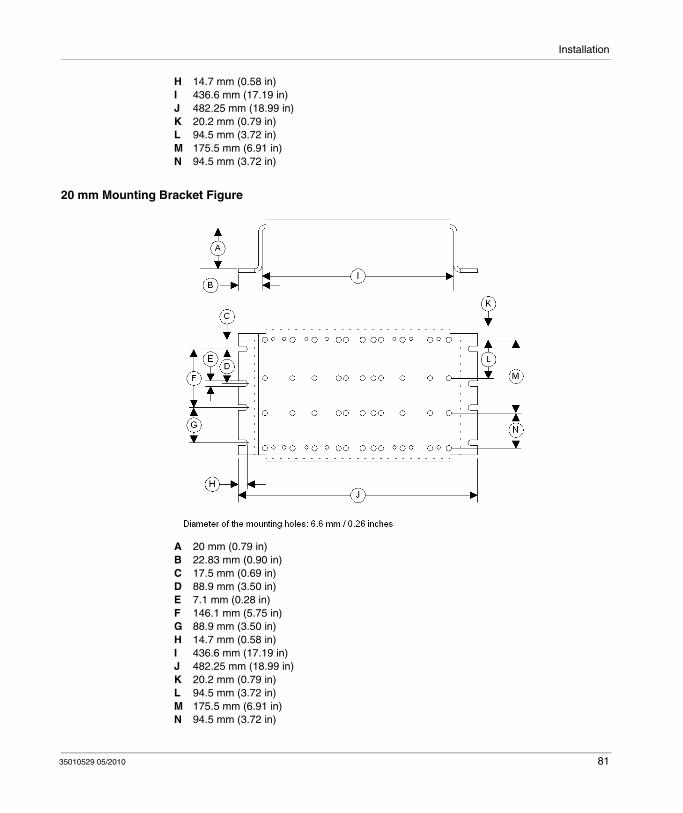
20 mm Mounting Bracket Figure
A 20 mm (0.79 in)B 22.83 mm (0.90 in)C 17.5 mm (0.69 in)D 88.9 mm (3.50 in)E 7.1 mm (0.28 in)F 146.1 mm (5.75 in)G 88.9 mm (3.50 in)H 14.7 mm (0.58 in)I 436.6 mm (17.19 in)J 482.25 mm (18.99 in)K 20.2 mm (0.79 in)L 94.5 mm (3.72 in)M 175.5 mm (6.91 in)N 94.5 mm (3.72 in)
35010529 05/2010 81

Installation
Mounting Quantum Modules
Overview
Quantum modules can be inserted into any slot of any rack. Although Power supply modules should be installed in the first or last slots, to have a cooling effect. The modules can be removed under power (hot swapped) without damaging modules or the rack.
Refer to the following figures and procedure when mounting modules.
NOTE: To provide EMC level, the mounting area of the CPU has to provide metallic contact. Therefore remove any labels in the affected area and clean the surface using solvent. The Quantum PLC enclosures and terminal strips are made of polycarbonates. This material can be damaged by strong alkalis and various hydrocarbons, esters, halogens and ketones in combination with heat. Common products containing these include detergents, PVC products, petroleum products, pesticides, disinfectants, paint removers, and spray paints. Use care in selecting and using cleaning solvents..
CAUTIONPOSSIBILITY OF MODULE DAMAGE
The inappropriate use of solvents, cutting oils, bug sprays and similar chemicals may cause the breakdown of module cases or terminal blocks.
Failure to follow these instructions can result in injury or equipment damage.
82 35010529 05/2010

Installation
Hot Swap Precautions
Unplugging and re-plugging the Quantum CPU when the rack is under power is not recommended. You are strongly advised to shut the power down before attempting to remove the CPU for any reason.
WARNINGUNEXPECTED SYSTEM BEHAVIOR - CPU HOT SWAP CONSEQUENCES
Do not Hot Swap Quantum CPU.
Failure to follow these instructions can result in death, serious injury, or equipment damage.
CAUTIONUNINTENDED EQUIPMENT OPERATION
Hot swapping an I/O module can generate an error code causing the module to stop functioning.
Failure to follow these instructions can result in injury or equipment damage.
35010529 05/2010 83

Installation
Mounting Bracket and Rack
The following steps describe the mounting of bracket and rack
Step Action
1 If required for the application, select and install a 20 mm or 125 mm mounting bracket to the rack using standard hardware.Front view:
1 Mounting bracket2 Rack
2 Select and install the appropriate rack to the mounting bracket using standard hardware and remove the plastic rack connector dust covers.
84 35010529 05/2010
Installation
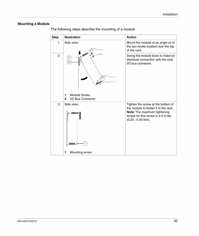
Mounting a Module
The following steps describe the mounting of a module
Step Illustration Action
1 Side view:
1 Module Hooks2 I/O Bus Connector
Mount the module at an angle on to the two hooks located near the top of the rack.
2 Swing the module down to make an electrical connection with the rack I/O bus connector.
3 Side view:
1 Mounting screw
Tighten the screw at the bottom of the module to fasten it to the rack.Note: The maximum tightening torque for this screw is 2-4 in-lbs (0.23 - 0.45 Nm).
35010529 05/2010 85

Installation
Mounting and Removing a Terminal Strip
Mounting a Terminal Strip
The following steps describe the mounting of a Terminal Strip
Step Action
1 Install the appropriate Terminal Strip on the module.Side view:
1 Module2 Mounting screw (top)3 Terminal Strip I/O screws4 Terminal Strip5 Mounting screw (bottom)
2 Tighten with the mounting screws at the top and bottom of the terminal with a philips screwdriver.Note: The maximum tightening torque for the mounting screws is 10 in-lbs (1.13 Nm).
3 Make I/O connections with a philips screwdriver as shown in the individual Quantum module wiring diagrams.Note: The maximum tightening torque for the terminal strip field wiring screws is 10 in-lbs (1.13 Nm).
86 35010529 05/2010
Installation
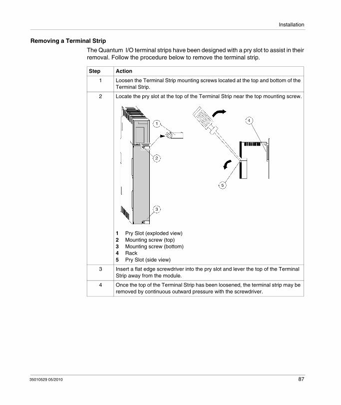
Removing a Terminal Strip
The Quantum I/O terminal strips have been designed with a pry slot to assist in their removal. Follow the procedure below to remove the terminal strip.
Step Action
1 Loosen the Terminal Strip mounting screws located at the top and bottom of the Terminal Strip.
2 Locate the pry slot at the top of the Terminal Strip near the top mounting screw.
1 Pry Slot (exploded view) 2 Mounting screw (top)3 Mounting screw (bottom)4 Rack5 Pry Slot (side view)
3 Insert a flat edge screwdriver into the pry slot and lever the top of the Terminal Strip away from the module.
4 Once the top of the Terminal Strip has been loosened, the terminal strip may be removed by continuous outward pressure with the screwdriver.
35010529 05/2010 87
Installation
Mounting Jumper Clips
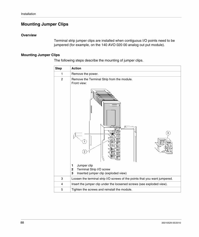
Overview
Terminal strip jumper clips are installed when contiguous I/O points need to be jumpered (for example, on the 140 AVO 020 00 analog out put module).
Mounting Jumper Clips
The following steps describe the mounting of jumper clips.
Step Action
1 Remove the power.
2 Remove the Terminal Strip from the module.Front view:
1 Jumper clip2 Terminal Strip I/O screw3 Inserted jumper clip (exploded view)
3 Loosen the terminal strip I/O screws of the points that you want jumpered.
4 Insert the jumper clip under the loosened screws (see exploded view).
5 Tighten the screws and reinstall the module.
88 35010529 05/2010

Installation
Removing a Module Door
Overview
The terminal strips have a removable door to facilitate access to the terminal strip. Remove the door before wiring a module.
Removing a Module Door
Step Action
1 Open the module door.
2 Place your thumb near the middle of the door.Front view:
3 With your thumb, apply pressure until the door bends and the door hinge pins pop out of the retaining holes at the top and bottom of the terminal strip.
4 After wiring the module, reinstall the door using the reverse of the above.
35010529 05/2010 89

Installation
90 35010529 05/2010
35010529 05/2010
II
CPUs
35010529 05/2010
Controller Modules (CPUs)
Introduction
This part provides information on Quantum Controller Modules (CPU).
What's in this Part?
This part contains the following chapters:
Chapter Chapter Name Page
7 General Information 93
8 Low End CPU 97
9 High End CPU 133
10 Memory Cards for High End CPU 181
91

CPUs
92 35010529 05/2010

35010529 05/2010
7
General Information
35010529 05/2010
General Information
Purpose
This chapter provides general information on Quantum Controller (CPU) modules.
What's in this Chapter?
This chapter contains the following topics:
Topic Page
CPU Overview 94
Machine Stop Codes 95
93

General Information
CPU Overview
Characteristics
CPU SRAM (bytes)
Max IEC Program
Max IEC Program (with PCMCIA)
Key Switch
Low End 140 CPU 311 10 2 MBytes 400 kBytes NA No
140 CPU 434 12• 2 MBytes 800 kBytes NA Yes
140 CPU 534 14• 4 MBytes 2.7 MBytes NA Yes
High End 140 CPU 651 50 2 MBytes 512 kBytes 7168 kBytes Yes
140 CPU 651 60 2 MBytes 1024 kBytes 7168 kBytes Yes
140 CPU 651 60S(Safety) 2 MBytes 1024 kBytes 7168 kBytes Yes
140 CPU 652 60 4 MBytes 3072 kBytes 7168 kBytes Yes
140 CPU 671 60 2 MBytes 1024 kBytes 7168 kBytes Yes
140 CPU 671 60S(Safety) 2 MBytes 1024 kBytes 7168 kBytes Yes
140 CPU 672 61 4 MBytes 3172 kBytes 8 MBytes Yes
94 35010529 05/2010

General Information
Machine Stop Codes
Machine Stop Code Descriptions
Error Stopped Codes
PLC unhealthy: This condition indicates that the CPU has not successfully completed one or more of its health diagnostics. Usually this means that the CPU needs to be replaced.PLC stopped: By itself, an 8000 hex is not an error but a CPU state. If, for example, a user issues a CPU stop command, the status register indicates 8000 hex. An error condition exists when 8000 is added with one or more of the previously defined errors (bits 0-14).Example:
2 stop codes are added,the 8100 stop code suggests that a PLC has stopped because of a software error detection. The controller is in halt and the application is stopped.3 stop codes are added,the 8180 stop code suggests that a PLC has stopped because of a software error detection and that the watchdog timer has expired.
Bad I/O map: This error occurs if the user declares more than one I/O drop in his configuration but does not have an RIO Head installed. This error may also occur if a drop configuration exceeds the maximum number of inputs/outputs allowable per drop.
Stop BitCode (hex)
Description
0x7FFF PLC unhealthy
0x8000 PLC stopped
0x8400 CPU has stopped because the firmware of the CRP module is not compatible with the application program in which the "Online Modification in RUN" check box has been selected
0x4000 Bad I/O traffic cop
0x2000 PLC in Dim awareness
0x1000 Bad port intervention
0x0100 Software error, controller in halt
0x0400 CRP firmware not compatible with CCOTF function
0x0080 Watchdog timer has expired
0x0010 RIO option error
0x0001 Bad configuration
35010529 05/2010 95
General Information
PLC unconfigured: Expect this condition if you are trying to log into the CPU for the first time. This error indicates that the CPU has not been configured. Write a configuration offline and transfer it to the CPU prior to logging into the CPU. If this error appears while you are seeking to communicate with a previously running CPU, this could indicate corrupted state memory in the CPU. You need to clear memory and attempt to reload the user logic program.Bad modbus port intervention: This error sometimes appears in conjunction with another error. The CPU is usually stopped when this error occurs. The error may also appear if you attempt to clear the system stop state. Try to clear user logic and reload.Software error, controller in halt: This error is usually caused by an incomplete or unsuccessful program load. Try to reload.Watchdog timer has expired: The error indicates that the CPU has taken too much time to complete its current scan. You may increase the Watchdog timer value. This error may indicate that the CPU is inoperable..RIO option has failed: The RIO option board (140 CRP 93• 00) is unhealthy. Replace the board. An error 8010 means that the CPU has stopped because RIO option board has to be replaced (unhealthy).Bad configuration: The most probable cause is that the memory has been modified through the MODBUS/MODBUS PLUS ports. If this error occurs during a program download, check your configuration data for values greater than the CPU's specified addressable range. This error can also appear if the CPU's memory is corrupt.
NOTE: The user can access the Stop codes and the sub Stop codes with the LCD keypad, available only with High-End processors, by selecting System info -> Stop codes.
If the sub Stop code is included between:50 and 98, the machine stopped because of a Traffic Cop error..101 and 137, the machine stopped because of an error of Peer cop.
You can see, in the words %SW124 and %SW125, information if it is a system error and the last default detected.
HALT state causes
The causes of the HALT state are saved in the system words: %SW125, %SW126 and %SW127. When the PLC is in HALT mode, the application is no longer executed, the IO are no longer applied.
To quit the HALT state, the user must either initialize or reload the application into the PLC.
96 35010529 05/2010

35010529 05/2010
8
Low End CPU
35010529 05/2010
Low End CPU
Purpose
This chapter provides information on the Low End Controller modules.
What's in this Chapter?
This chapter contains the following topics:
Topic Page
Presentation 98
Front Panel Switches 99
Rear Panel Switches 102
Key Switches 103
Modbus Connectors 106
Indicators 108
Processor Configuration Screen 111
140 CPU 311 10 Specifications 122
140 CPU 434 12A Specifications 124
140 CPU 534 14A/U Specifications 127
140 CPU 534 14B/U Specifications 130
97
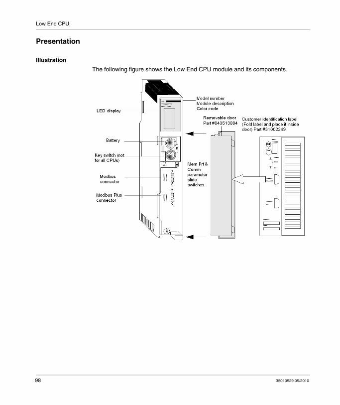
Low End CPU
Presentation
Illustration
The following figure shows the Low End CPU module and its components.
98 35010529 05/2010

Low End CPU
Front Panel Switches
Front Panel Switches
Two three-position slide switches are located on the front of the CPU. The left switch is used for memory protection when in the top position and no memory protection in the middle and bottom positions. The switch on the right is used to select the Comm parameter settings for the Modbus (RS-232) ports.
NOTE: The memory switch selection is taken into account immediately.
NOTE: The modbus switch selection is taken into account after a Power off/on of the Quantum PLC
WARNINGUNINTENDED EQUIPMENT OPERATION
Do not allow an automatic backup restore upon cycling power to the PLC. The backup restore function reloads in the PLC memory the version saved on the memory card, that can be different than the one that was running before the power off.
Failure to follow these instructions can result in death, serious injury, or equipment damage.
35010529 05/2010 99
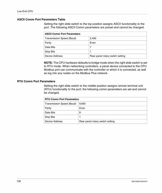
Low End CPU
ASCII Comm Port Parameters Table
Setting the right slide switch to the top position assigns ASCII functionality to the port. The following ASCII Comm parameters are preset and cannot be changed:
NOTE: The CPU hardware defaults to bridge mode when the right slide switch is set to RTU mode. When networking controllers, a panel device connected to the CPU Modbus port can communicate with the controller to which it is connected, as well as log into any nodes on the Modbus Plus network.
RTU Comm Port Parameters
Setting the right slide switch to the middle position assigns remote terminal unit (RTU) functionality to the port; the following comm parameters are set and cannot be changed.
ASCII Comm Port Parameters
Transmission Speed (Baud) 2,400
Parity Even
Data Bits 7
Stop Bits 1
Device Address Rear panel rotary switch setting
RTU Comm Port Parameters
Transmission Speed (Baud) 9,600
Parity Even
Data Bits 8
Stop Bits 1
Device Address Rear panel rotary switch setting
100 35010529 05/2010
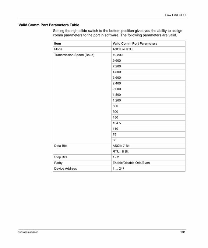
Low End CPU
Valid Comm Port Parameters Table
Setting the right slide switch to the bottom position gives you the ability to assign comm parameters to the port in software. The following parameters are valid.
Item Valid Comm Port Parameters
Mode ASCII or RTU
Transmission Speed (Baud) 19,200
9,600
7,200
4,800
3,600
2,400
2,000
1,800
1,200
600
300
150
134.5
110
75
50
Data Bits ASCII: 7 Bit
RTU: 8 Bit
Stop Bits 1 / 2
Parity Enable/Disable Odd/Even
Device Address 1 ... 247
35010529 05/2010 101

Low End CPU
Rear Panel Switches
Rear Panel Switches
Two rotary switches (refer to the illustration and table below) are located on the rear panel of the CPU. They are used for setting the Modbus Plus node and Modbus port addresses.
NOTE: The highest address that may be set with these switches is 64.
SW1 (the top switch) sets the upper digit (tens) of the address; SW2 (the bottom switch) sets the lower digit (ones) of the address. The illustration below shows the correct setting for an example address of 13.
SW1 and SW2 Switches Figure
The following figure shows the SW1 and SW2 settings.
SW1 and SW2 Address Settings Table
The following table shows the SW1 and SW2 address settings.
NOTE: If "0" or an address greater than 64 is selected, the Modbus + LED will be "on" steady, to indicate the selection of an invalid address.
Node Address SW1 SW2
1 ... 9 0 1 ... 9
10 ... 19 1 0 ... 9
20 ... 29 2 0 ... 9
30 ... 39 3 0 ... 9
40 ... 49 4 0 ... 9
50 ... 59 5 0 ... 9
60 ... 64 6 0 ... 4
102 35010529 05/2010
Low End CPU
Key Switches
Overview
The low end CPUs have 1,435 kb of Flash EPROM memory, which can be used to save the program and the variables’ initial values. On power-up, if there is a program in Flash memory, you can choose one of three operating modes, using the PLC MEM switch on the CPU’s front panel. The 140 CPU 434 12A and 140 CPU 534 12A are equiped with a key switch with the Start, Mem Prt, and Stop positions. The 140 CPU 311 10 features a slide switch with the Mem Prt On, Not Used, and Mem Prt Off options.
Behavior on Power Up
The CPU’s behavior on power up is determined by the key switch position. The behavior could be:
Cold Restart Warm Restart
NOTE: To ensure a warm restart of an application following an OS upgrade on Quatum CPUs, click PLC → Project Backup... → Backup Clear.
This section describes the three positions of the rotary key switch, and their respective meanings.
WARNINGUNEXPECTED EQUIPMENT OPERATION
Always perform a Back Up Clear after an OS upgrade of the Quantum (140 CPU 534 •, 140 CPU 434 14A, 140 CPU 311 10) CPUs.
Failure to follow these instructions can result in death, serious injury, or equipment damage.
35010529 05/2010 103
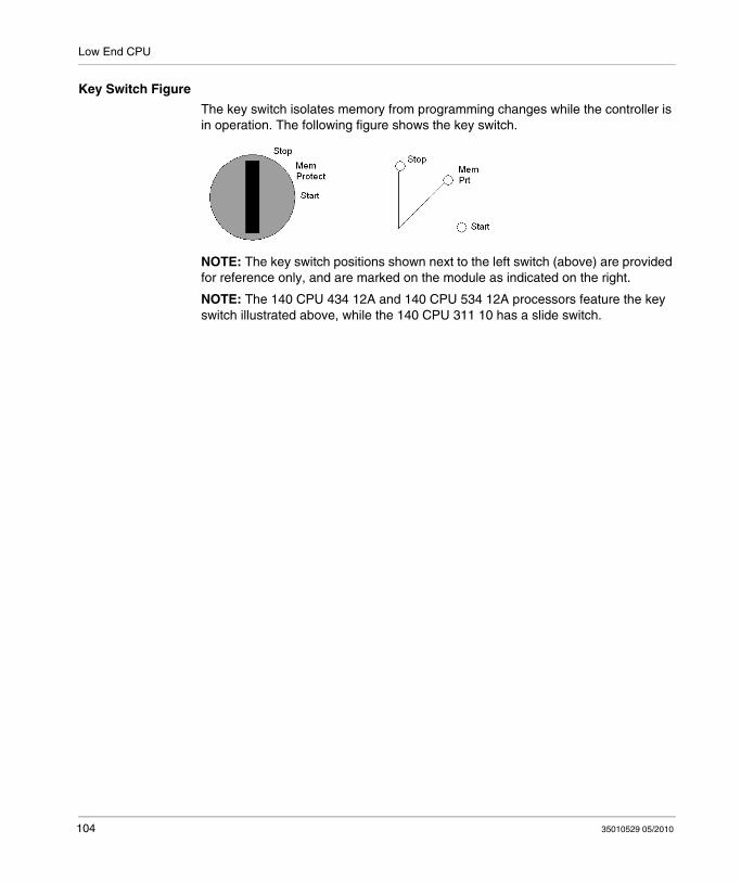
Low End CPU
Key Switch Figure
The key switch isolates memory from programming changes while the controller is in operation. The following figure shows the key switch.
NOTE: The key switch positions shown next to the left switch (above) are provided for reference only, and are marked on the module as indicated on the right.
NOTE: The 140 CPU 434 12A and 140 CPU 534 12A processors feature the key switch illustrated above, while the 140 CPU 311 10 has a slide switch.
104 35010529 05/2010

Low End CPU
Key Switch Description Table
The following table provides key/slider switch information for these three low end CPUs.
CPU Type Switch Position
Behaviour Protected? Accepts Stop or Start?
Key Switch Transition
Quantum 140 CPU 311 10
Mem Prt On The application in Flash memory is not transferred to internal RAM; a warm restart of the application is triggered.
Y N From Mem Prt Off: does not modify last controller state and rejects programmer changes.
Not used Do not use this position, because it may lead to undefined operation
Y N n/a
Mem Prt Off The application in Flash memory is automatically transferred to internal RAM when the PLC is powered up. A cold restart of the application is triggered.
N Y From Mem Prt On : enables programmer changes and starts controller if stopped.
Quantum 140 CPU 434 12A 140 CPU 534 14A
Stop The application in Flash memory is not transferred to internal RAM; a warm restart of the application is triggered.
Y N From Start or Mem Prt: stops controller, if running, and voids programmer changes.
Mem Prt The application in Flash memory is not transferred to internal RAM. A warm restart of the application is triggered.
Y N From Stop or Start: inhibits program changes, controller run status is unchanged.
Start The application in Flash memory is automatically transferred to internal RAM when the PLC is powered up. A cold restart of the application is triggered.
N Y From Stop: enables programmer changes, starts controller. From Mem Prt: accepts programmer changes, starts controller if stopped.
35010529 05/2010 105

Low End CPU
Modbus Connectors
Modbus Connector Pinouts
Quantum CPUs are equipped with a nine-pin RS-232C connector that supports Schneider Electric’s proprietary Modbus communication protocol. The following is the Modbus port pinout connections for nine-pin and 25-pin connections.
Modbus Port 1 has full modem interfacing capabilities Modbus Port 2 RTS/CTS connections function properly for normal non-modem communications but do not support modems.
NOTE: Although the Modbus ports electrically support existing Modbus cables, it is recommended that a Modbus programming cable (Part # 990 NAA 263 20 or 990 NAA 263 50) be used. This cable has been designed to fit under the door of a Quantum CPU or NOM module.
Modbus Ports Pinout Connections Figure
The following figure shows the Modbus port pinout connections for nine-pin and 25-pin connections.
The following is the abbreviation key for the above figure.
TX: Transmitted Data DTR: Data Terminal Ready
RX: Received Data CTS: Clear to Send
RTS: Request to Send NC: No Connection
DSR: Data Set Ready CD: Carrier Detect
106 35010529 05/2010

Low End CPU
Modbus Ports Pinout Connections for Portable Computers
The following figure shows the Modbus port pinout connections for 9-pin portable computers.
35010529 05/2010 107
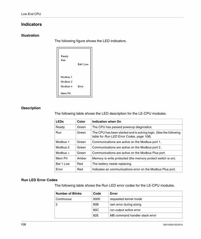
Low End CPU
Indicators
Illustration
The following figure shows the LED indicators.
Description
The following table shows the LED description for the LE-CPU modules.
Run LED Error Codes
The following table shows the Run LED error codes for the LE-CPU modules.
LEDs Color Indication when On
Ready Green The CPU has passed powerup diagnostics.
Run Green The CPU has been started and is solving logic. (See the following table for Run LED Error Codes, page 108).
Modbus 1 Green Communications are active on the Modbus port 1.
Modbus 2 Green Communications are active on the Modbus port 2.
Modbus + Green Communications are active on the Modbus Plus port.
Mem Prt Amber Memory is write protected (the memory protect switch is on).
Bat 1 Low Red The battery needs replacing.
Error Red Indicates an communications error on the Modbus Plus port.
Number of Blinks Code Error
Continuous 0000 requested kernel mode
2 80B ram error during sizing
80C run output active error
82E MB command handler stack error
108 35010529 05/2010
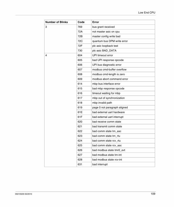
Low End CPU
3 769 bus grant received
72A not master asic on cpu
72B master config write bad
72C quantum bus DPM write error
72F plc asic loopback test
730 plc asic BAD_DATA
4 604 UPI timeout error
605 bad UPI response opcode
606 UPI bus diagnostic error
607 modbus cmd-buffer overflow
608 modbus cmd-length is zero
609 modbus abort command error
614 mbp bus interface error
615 bad mbp response opcode
616 timeout waiting for mbp
617 mbp out of synchronization
618 mbp invalid path
619 page 0 not paragraph aligned
61E bad external uart hardware
61F bad external uart interrupt
620 bad receive comm state
621 bad transmit comm state
622 bad comm state trn_asc
623 bad comm state trn_rtu
624 bad comm state rcv_rtu
625 bad comm state rcv_asc
626 bad modbus state tmr0_evt
627 bad modbus state trn-int
628 bad modbus state rcv-int
631 bad interrupt
Number of Blinks Code Error
35010529 05/2010 109

Low End CPU
NOTE: Information in the Code column is visible only with the Flash download utility.
5 503 ram address test error
52D P.O.S.T BAD MPU ERROR
6 402 ram data test error
7 300 EXEC not loaded
301 EXEC Checksum
8 8001 Kernal prom checksum error
8002 flash prog / erase error
8003 unexpected executive return
Number of Blinks Code Error
110 35010529 05/2010
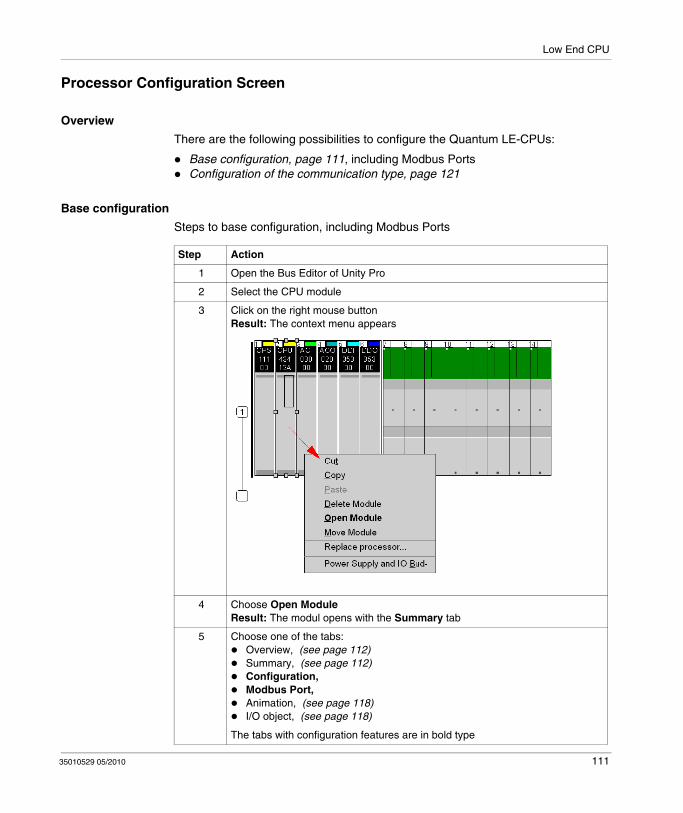
Low End CPU
Processor Configuration Screen
Overview
There are the following possibilities to configure the Quantum LE-CPUs:
Base configuration, page 111, including Modbus PortsConfiguration of the communication type, page 121
Base configuration
Steps to base configuration, including Modbus Ports
Step Action
1 Open the Bus Editor of Unity Pro
2 Select the CPU module
3 Click on the right mouse buttonResult: The context menu appears
4 Choose Open ModuleResult: The modul opens with the Summary tab
5 Choose one of the tabs:Overview, (see page 112)Summary, (see page 112)Configuration, Modbus Port, Animation, (see page 118)I/O object, (see page 118)
The tabs with configuration features are in bold type
35010529 05/2010 111
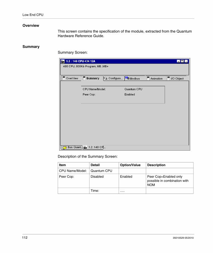
Low End CPU
Overview
This screen contains the specification of the module, extracted from the Quantum Hardware Reference Guide.
Summary
Summary Screen:
Description of the Summary Screen:
Item Detail Option/Value Description
CPU Name/Model: Quantum CPU
Peer Cop: Disabled Enabled Peer Cop=Enabled only possible in combination with NOM
Time: .....
112 35010529 05/2010
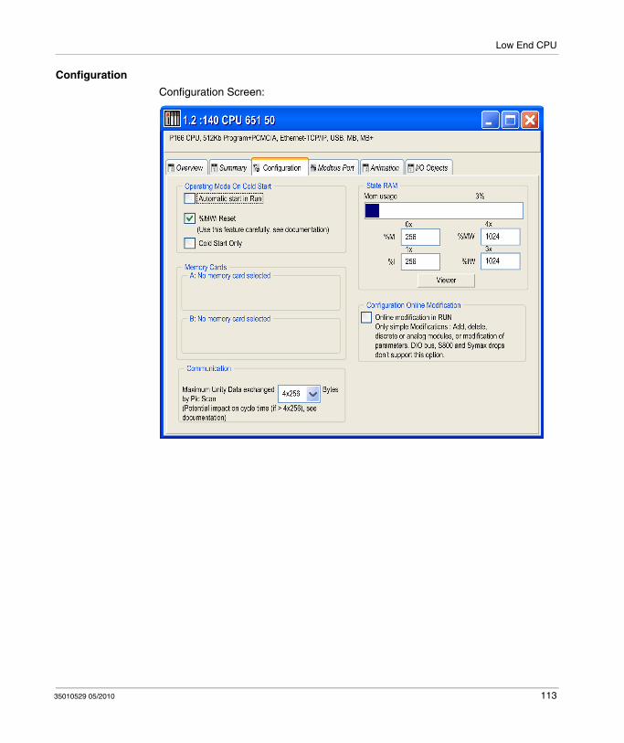
Low End CPU
Configuration
Configuration Screen:
35010529 05/2010 113
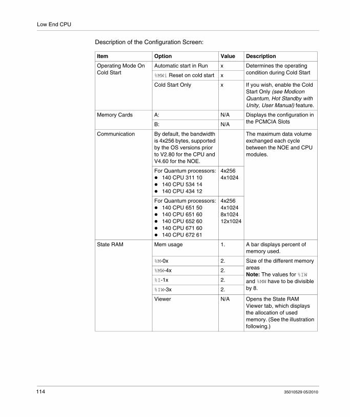
Low End CPU
Description of the Configuration Screen:
Item Option Value Description
Operating Mode On Cold Start
Automatic start in Run x Determines the operating condition during Cold Start%MWi Reset on cold start x
Cold Start Only x If you wish, enable the Cold Start Only (see Modicon Quantum, Hot Standby with Unity, User Manual) feature.
Memory Cards A: N/A Displays the configuration in the PCMCIA SlotsB: N/A
Communication By default, the bandwidth is 4x256 bytes, supported by the OS versions prior to V2.80 for the CPU and V4.60 for the NOE.
The maximum data volume exchanged each cycle between the NOE and CPU modules.
For Quantum processors:140 CPU 311 10140 CPU 534 14140 CPU 434 12
4x2564x1024
For Quantum processors:140 CPU 651 50140 CPU 651 60140 CPU 652 60140 CPU 671 60140 CPU 672 61
4x2564x10248x102412x1024
State RAM Mem usage 1. A bar displays percent of memory used.
%M-0x 2. Size of the different memory areasNote: The values for %IW and %MW have to be divisible by 8.
%MW-4x 2.
%I-1x 2.
%IW-3x 2.
Viewer N/A Opens the State RAM Viewer tab, which displays the allocation of used memory. (See the illustration following.)
114 35010529 05/2010

Low End CPU
Per Quantum 140 CPU 3••, 140 CPU 4•• and 140 CPU 5•• the %MWi value is as follows:
NOTE: %MWi will reset with the cold start %S0 or a loading program. Cold start is typically after a program load, %S0 can be set with the user program to initiate a cold start.
Configuration Online Modification
Online modif in RUN x This check box allows to:Add or delete discrete or analog modules, Modify Parameters
NOTE: These modifications can be done in RUN.
1. The value (expressed as a percentage and displayed on the scale) depends on the memory usage of the Hot Standby configuration.2. Enter the appropriate values. All values depend on Hot Standby configuration.
Power ON:without cold start
Power ON: with cold start
%MWi reset box
Unchecked %MWi keeps their value
%MWi = 0
Checked Initial value of %MWi
Item Option Value Description
35010529 05/2010 115
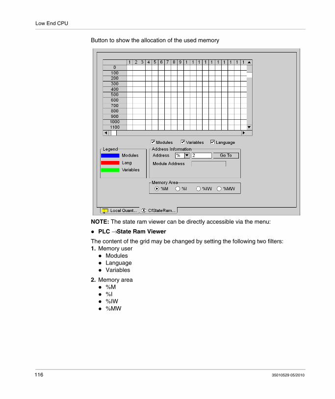
Low End CPU
Button to show the allocation of the used memory
NOTE: The state ram viewer can be directly accessible via the menu:
PLC → State Ram Viewer
The content of the grid may be changed by setting the following two filters:1. Memory user
ModulesLanguageVariables
2. Memory area%M%I%IW%MW
116 35010529 05/2010
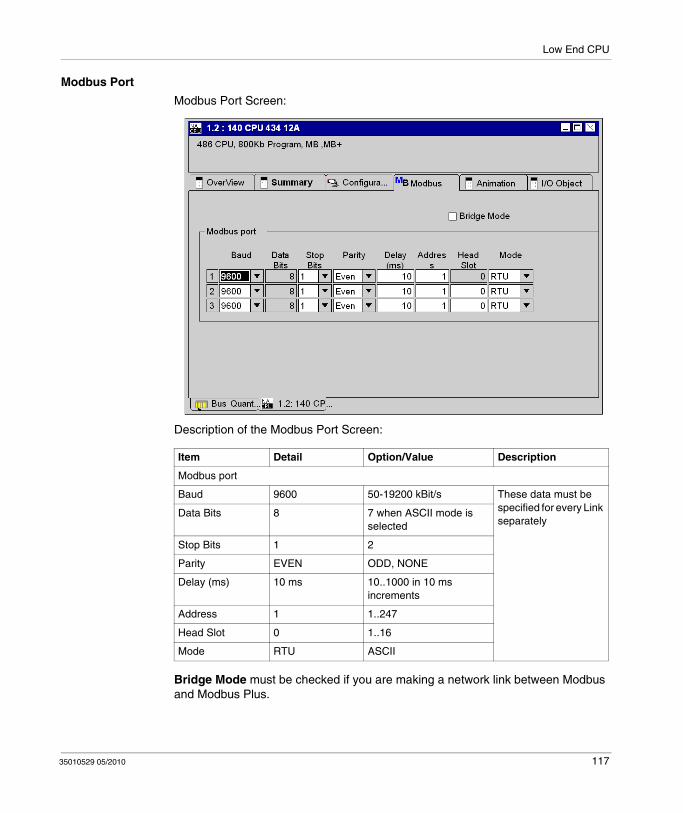
Low End CPU
Modbus Port
Modbus Port Screen:
Description of the Modbus Port Screen:
Bridge Mode must be checked if you are making a network link between Modbus and Modbus Plus.
Item Detail Option/Value Description
Modbus port
Baud 9600 50-19200 kBit/s These data must be specified for every Link separately
Data Bits 8 7 when ASCII mode is selected
Stop Bits 1 2
Parity EVEN ODD, NONE
Delay (ms) 10 ms 10..1000 in 10 ms increments
Address 1 1..247
Head Slot 0 1..16
Mode RTU ASCII
35010529 05/2010 117
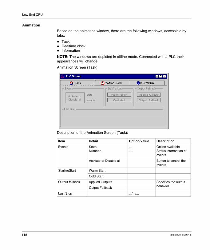
Low End CPU
Animation
Based on the animation window, there are the following windows, accessible by tabs:
TaskRealtime clockInformation
NOTE: The windows are depicted in offline mode. Connected with a PLC their appearances will change.
Animation Screen (Task):
Description of the Animation Screen (Task):
Item Detail Option/Value Description
Events State:Number:
...
...Online available Status information of events
Activate or Disable all Button to control the events
Start/reStart Warm Start
Cold Start
Output fallback Applied Outputs Specifies the output behaviorOutput Fallback
Last Stop .../.../...
118 35010529 05/2010
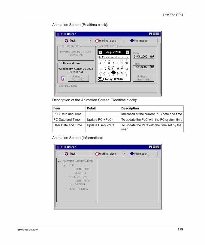
Low End CPU
Animation Screen (Realtime clock):
Description of the Animation Screen (Realtime clock):
Animation Screen (Information):
Item Detail Description
PLC Date and Time Indication of the current PLC date and time
PC Date and Time Update PC->PLC To update the PLC with the PC system time
User Date and Time Update User->PLC To update the PLC with the time set by the user
35010529 05/2010 119

Low End CPU
Description of the Animation Screen (Information):
I/O Object
The I/O objects tab is used to associate variables with the module I/Os and to manage these different variables. This tab is describe in chapter I/O Management (see Unity Pro, Operating Modes, ).
Item Detail Option/Value Description
System Information PLC / Identification
PLC RangeProcessor NameProcessor VersionHardware IDNetwork address
Only Online available
PLC / Memory RAM CPU
Application / Identification
NameCreation ProductDateModification ProductDateVersionSignature
Application / Option
Empty Terminal SupportUpload InformationCommentsAnimation TableGlobal ProtectionSection ProtectionApplication DiagnosticForced Bits
Hotstandby Bit NumberStatus RegisterPLC ModeOther PLC ModePLCs matching LogicPLC switchCoprocessor HealthHot Standby Capability
120 35010529 05/2010

Low End CPU
Configuration of the communication type
Steps to configuration of the communication type
Step Action
1 Open the Bus Editor of Unity Pro
2 Move the mouse over the rectangle of the CPU moduleResult: The mouse pointer changes to a hand
3 Doubleclick on the left mouse buttonResult: A sub-dialog appears
4 Choose one of the following options:NoneDIO busPeer Cop
35010529 05/2010 121

Low End CPU
140 CPU 311 10 Specifications
General Specifications
Processor
Memory
Reference Capacity
Local I/O
Communication ports 2 Modbus (RS-232)1 Modbus Plus (RS-485)
Bus current required 1250 mA
Max. number of NOM, NOE, PTQ PDP MV1 and MMS modules supported (any combination)
2
Key switch No
Model Intel 486
Math processor No
Watchdog timer 250 ms S/W adjustable
RAM 2 Mb
IEC program memory (max.) 400 kb
Flash 2 Mb
Discrete (bits) 51712 b (any mix)
Registers (words) 9672 max.
Max. I/O words unlimited I/O
Max. I/O racks 2
122 35010529 05/2010

Low End CPU
Remote I/O
Distributed I/O
Battery and Clock
Diagnostics
Max. I/O words per drop 64 in / 64 out*
Max. number of remote drops 31
* This information can be a mix of discrete or register I/O. For each word of configured I/O, one of the I/O words must be subtracted from the total available.
Number of networks per system 1 (3**)
Max. words per network 500 IN and 500 OUTFor every DIO drop, there is a minimum of two words input of overhead
Max. words per node 30 in / 32 out
Max. number of DIO drops per network 64
** Requires the use of the 140 NOM 21• 00 option module.
Type 3 V Lithium
Service life 1200 mAh
Shelf life 10 years with 0.5% loss of capacity per year
Battery load current @ power-off typical: 5 μAmax. 110 μA
TOD clock +/- 8.0 s/day @ 0 ... 60 ° C
Power-up RAMRAM addressExecutive checksumUser logic checkProcessor
Run time RAMRAM addressExecutive checksumUser logic check
35010529 05/2010 123
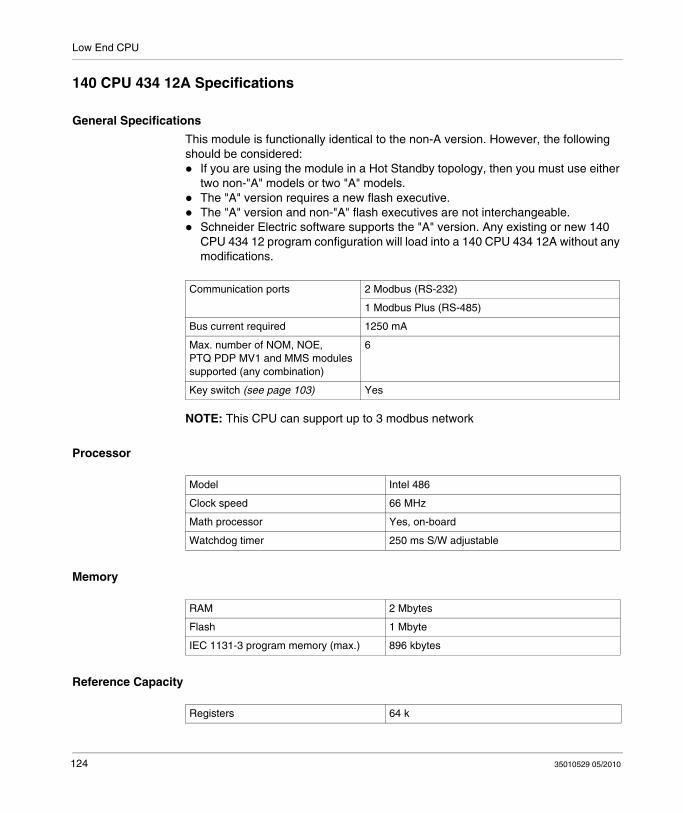
Low End CPU
140 CPU 434 12A Specifications
General Specifications
This module is functionally identical to the non-A version. However, the following should be considered:
If you are using the module in a Hot Standby topology, then you must use either two non-"A" models or two "A" models.The "A" version requires a new flash executive.The "A" version and non-"A" flash executives are not interchangeable.Schneider Electric software supports the "A" version. Any existing or new 140 CPU 434 12 program configuration will load into a 140 CPU 434 12A without any modifications.
NOTE: This CPU can support up to 3 modbus network
Processor
Memory
Reference Capacity
Communication ports 2 Modbus (RS-232)
1 Modbus Plus (RS-485)
Bus current required 1250 mA
Max. number of NOM, NOE, PTQ PDP MV1 and MMS modules supported (any combination)
6
Key switch (see page 103) Yes
Model Intel 486
Clock speed 66 MHz
Math processor Yes, on-board
Watchdog timer 250 ms S/W adjustable
RAM 2 Mbytes
Flash 1 Mbyte
IEC 1131-3 program memory (max.) 896 kbytes
Registers 64 k
124 35010529 05/2010
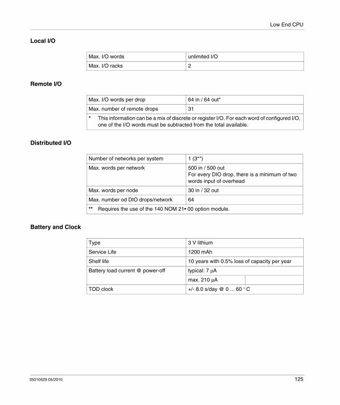
Low End CPU
Local I/O
Remote I/O
Distributed I/O
Battery and Clock
Max. I/O words unlimited I/O
Max. I/O racks 2
Max. I/O words per drop 64 in / 64 out*
Max. number of remote drops 31
* This information can be a mix of discrete or register I/O. For each word of configured I/O, one of the I/O words must be subtracted from the total available.
Number of networks per system 1 (3**)
Max. words per network 500 in / 500 outFor every DIO drop, there is a minimum of two words input of overhead
Max. words per node 30 in / 32 out
Max. number od DIO drops/network 64
** Requires the use of the 140 NOM 21• 00 option module.
Type 3 V lithium
Service Life 1200 mAh
Shelf life 10 years with 0.5% loss of capacity per year
Battery load current @ power-off typical: 7 μA
max. 210 μA
TOD clock +/- 8.0 s/day @ 0 ... 60 ° C
35010529 05/2010 125

Low End CPU
Diagnostics
Power-up RAMRAM addressExecutive ChecksumUser Logic CheckProcessor
Run time RAMRAM addressExecutive ChecksumUser Logic Check
126 35010529 05/2010

Low End CPU
140 CPU 534 14A/U Specifications
General Specifications
This module is functionally identical to the non-A version. However, the following should be considered:
If you are using the module in a Hot Standby topology, then you must use either two non-A models or two A/U models.The A/U model requires a new flash executive.The A/U and the non-A flash executives are not interchangeable.Schneider Electric software supports the A/U model. Any existing or new 140 CPU 534 14 program configuration will load into a 140 CPU 534 14A/U without any modifications.
NOTE: This CPU can support up to 3 modbus network
Processor
Memory
Reference Capacity
Communication ports 2 Modbus (RS-232)
1 Modbus Plus (RS-485)
Bus current required 1250 mA
Max. number of NOM, NOE, PTQ PDP MV1 and MMS modules supported (any combination)
6
Key switch (see page 103) Yes
Model Intel 586 DX
Clock speed 133 MHz
On-board math processor Yes, on-board
Watchdog timer 250 ms S/W adjustable
RAM 4 Mb
Flash 1 Mb
IEC 1131-3 program memory (max.) 2.7 Mb
Discrete (bits) 64 kb (any combination)
Registers (words) 57 kb max.
35010529 05/2010 127
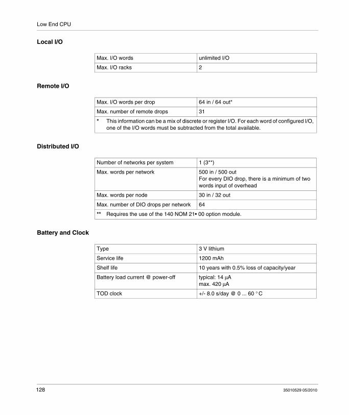
Low End CPU
Local I/O
Remote I/O
Distributed I/O
Battery and Clock
Max. I/O words unlimited I/O
Max. I/O racks 2
Max. I/O words per drop 64 in / 64 out*
Max. number of remote drops 31
* This information can be a mix of discrete or register I/O. For each word of configured I/O, one of the I/O words must be subtracted from the total available.
Number of networks per system 1 (3**)
Max. words per network 500 in / 500 outFor every DIO drop, there is a minimum of two words input of overhead
Max. words per node 30 in / 32 out
Max. number of DIO drops per network 64
** Requires the use of the 140 NOM 21• 00 option module.
Type 3 V lithium
Service life 1200 mAh
Shelf life 10 years with 0.5% loss of capacity/year
Battery load current @ power-off typical: 14 μAmax. 420 μA
TOD clock +/- 8.0 s/day @ 0 ... 60 ° C
128 35010529 05/2010

Low End CPU
Diagnostics
Power-up RAMRAM addressExecutive checksumUser logic checkProcessor
Run time RAMRAM addressExecutive checksumUser logic check
35010529 05/2010 129

Low End CPU
140 CPU 534 14B/U Specifications
General Specifications
This module is functionally identical to the non-B version. However, the following should be considered:
If you are using the module in a Hot Standby topology, then you must use either two non-B models or two B/U models.The B/U model requires a new flash executive.The B/U and the non-B flash executives are not interchangeable.Schneider Electric software supports the B/U model. Any existing or new 140 CPU 534 14 program configuration will load into a 140 CPU 534 14B/U without any modifications.
NOTE: This CPU can support up to 3 modbus network
Processor
Memory
Reference Capacity
Communication ports 2 Modbus (RS-232)
1 Modbus Plus (RS-485)
Bus current required 1250 mA
Max. number of NOM, NOE, PTQ PDP MV1 and MMS modules supported (any combination)
6
Key switch (see page 103) Yes
Model Intel 486 DX4
Clock speed 100 MHz
On-board math processor Yes, on-board
Watchdog timer 250 ms S/W adjustable
RAM 4 Mb
Flash 1 Mb
IEC 1131-3 program memory (max.) 2.7 Mb
Discrete (bits) 64 kb (any combination)
Registers (words) 57 kb max.
130 35010529 05/2010

Low End CPU
Local I/O
Remote I/O
Distributed I/O
Battery and Clock
Max. I/O words unlimited I/O
Max. I/O racks 2
Max. I/O words per drop 64 in / 64 out*
Max. number of remote drops 31
* This information can be a mix of discrete or register I/O. For each word of configured I/O, one of the I/O words must be subtracted from the total available.
Number of networks per system 1 (3**)
Max. words per network 500 in / 500 outFor every DIO drop, there is a minimum of two words input of overhead
Max. words per node 30 in / 32 out
Max. number of DIO drops per network 64
** Requires the use of the 140 NOM 21• 00 option module.
Type 3 V lithium
Service life 1200 mAh
Shelf life 10 years with 0.5% loss of capacity/year
Battery load current @ power-off typical: 14 μAmax. 420 μA
TOD clock +/- 8.0 s/day @ 0 ... 60 ° C
35010529 05/2010 131

Low End CPU
Diagnostics
Power-up RAMRAM addressExecutive checksumUser logic checkProcessor
Run time RAMRAM addressExecutive checksumUser logic check
132 35010529 05/2010

35010529 05/2010
9
High End CPU
35010529 05/2010
High End CPU
Purpose
This chapter provides information on the High End Controller modules.
Quantum SIL2 Hot StandBy Offer
Read thoroughly the Quantum Safety PLC - Safety Manual (part number 33003879) to build a safety PLC according to the safety certifications. Schneider Electric provides a range of products that are certified to be used in a IEC 61508 and SIL2 safety system.
This range includes:safety CPU modules (140 CPU 651 60S and 140 CPU 671 60S)safety I/O modules (140 SAI 940 00S, 140 SDI 953 00S, 140 SDO 953 00S)non-interfering modulesUnity Pro XLS
NOTE: If remote racks or hot standby functionality is required, you can use the safety modules with existing Quantum remote I/O modules (140 CRP 932 00 and 140 CRA 932 00 only). If other I/O modules are present in the rack, they must either be certified non-interfering modules or they must be removed or exchanged for certified non-interfering modules that will provide similar capability.
133

High End CPU
What's in this Chapter?
This chapter contains the following topics:
Topic Page
Physical Presentation and Mounting of Standard High End Modules 135
Standalone Safety CPU 137
Physical presentation and mounting of Hot StandBy High End modules 139
Hot Standby Safety CPU Specifics 140
Controls and Displays 143
Indicators 147
Modbus port 149
Using the LCD Display Screens 151
Processor Configuration Screen 162
140 CPU 651 50 Specifications 164
140 CPU 651 60 Specifications 167
140 CPU 651 60S Specifications 170
140 CPU 652 60 Specifications 172
140 CPU 671 60 Specifications 174
140 CPU 671 60S Specifications 177
140 CPU 672 61 Specifications 179
134 35010529 05/2010

High End CPU
Physical Presentation and Mounting of Standard High End Modules
Illustration
The figure shows a standard High End module and its components.
1 model number, module description, color code2 lens cover (open)3 LCD display (here covered by the lens cover)4 key switch5 keypad (with 2 red LED indicators)6 modbus port (RS-232) (RS-485)7 USB port8 Modbus Plus port9 PCMCIA slots (A and B)10 LED indicators (yellow) for Ethernet communication11 Ethernet port 12 battery (user installed)13 reset button14 2 screws
NOTE: Quantum High End processors are equipped with two receptacles (A and B) in which to install Schneider PCMCIA cards (other cards are not accepted).
35010529 05/2010 135

High End CPU
Mounting
Mounting the module onto the central back plane:
1 Hang the module.2 Screw the module to the back plane.
136 35010529 05/2010

High End CPU
Standalone Safety CPU
Introduction
For use in standalone SIL3 solutions, the 140 CPU 651 60S Quantum Safety CPU is certified
The safety CPU includes a PCMCIA memory card (see Modicon Quantum, Quantum Safety PLC, Safety Reference Manual), but its use and presence is not mandatory.
Description of the Internal CPU Architecture
The Quantum Safety CPU contains 2 different processors, an Intel Pentium and an application processor. Each one executes the Safety logic in its own memory area and both compare the results of the execution at the end of each cycle.
Two CPUs are available:140 CPU 651 60S (Standalone Safety CPU)140 CPU 671 60S (Hot Standby Safety CPU)
The following figure shows the internal architecture of the Quantum Safety CPU:
35010529 05/2010 137
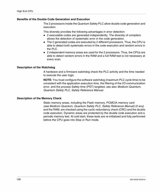
High End CPU
Benefits of the Double Code Generation and Execution
The 2 processors inside the Quantum Safety PLC allow double code generation and execution.
This diversity provides the following advantages in error detection:2 executable codes are generated independently. The diversity of compilers allows the detection of systematic error in the code generation.The 2 generated codes are executed by 2 different processors. Thus, the CPU is able to detect both systematic errors in the code execution and random errors in the PLC.2 independent memory areas are used for the 2 processors. Thus, the CPUs are able to detect random errors in the RAM and a full RAM test is not necessary at every scan.
Description of the Watchdog
A hardware and a firmware watchdog check the PLC activity and the time needed to execute the user logic.
NOTE: You must configure the software watchdog (maximum PLC cycle time) to be consistent with the application execution time, the filtering of the I/O communication error, and the process Safety time (PST) targeted, see also Modicon Quantum, Quantum Safety PLC, Safety Reference Manual.
Description of the Memory Check
Static memory areas, including the Flash memory, PCMCIA memory card (see Modicon Quantum, Quantum Safety PLC, Safety Reference Manual) (if any) and the RAM, are checked using the cyclic redundancy check (CRC) and the double code execution. Dynamic areas are protected by the double code execution and a periodic memory test. At cold start, these tests are re-initialized and fully performed before the CPU goes into Stop or Run mode.
138 35010529 05/2010
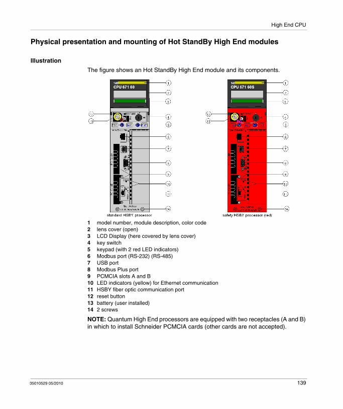
High End CPU
Physical presentation and mounting of Hot StandBy High End modules
Illustration
The figure shows an Hot StandBy High End module and its components.
1 model number, module description, color code2 lens cover (open)3 LCD Display (here covered by lens cover)4 key switch5 keypad (with 2 red LED indicators)6 Modbus port (RS-232) (RS-485)7 USB port8 Modbus Plus port9 PCMCIA slots A and B10 LED indicators (yellow) for Ethernet communication11 HSBY fiber optic communication port12 reset button13 battery (user installed)14 2 screws
NOTE: Quantum High End processors are equipped with two receptacles (A and B) in which to install Schneider PCMCIA cards (other cards are not accepted).
35010529 05/2010 139

High End CPU
Hot Standby Safety CPU Specifics
Introduction
The 140 CPU 671 60S Quantum Safety CPU module is certified for use in Hot Standby SIL3 solutions compliant to 61508 IEC standard. For more details according to the safety certifications see the Quantum Safety PLC (see Modicon Quantum, Quantum Safety PLC, Safety Reference Manual).
In a Hot Standby configuration, 1 CPU is the Primary CPU and the other is the Standby CPU.
The Hot Standby Safety CPU differs from the standalone Safety CPU in the use of the Ethernet port. In the standalone Safety CPU, it is used to communicate with other devices using a normal Ethernet cable. In the Hot Standby Safety CPU, it is used to exchange data between the Primary CPU and the Standby CPU controller using a fiber optic link. Because the fiber optic link is not part of the Safety loop, the PFD and PFH values of the Hot Standby CPU are the same as those of the standalone CPU. Each Safety CPU includes a PCMCIA memory card (see Modicon Quantum, Quantum Safety PLC, Safety Reference Manual), but its use and presence is not mandatory.
Description of the Hot Standby Configuration
The Hot Standby configuration contains 2 identical local racks and at least 1 remote I/O drop because I/Os cannot be placed in the local rack of a Hot Standby configuration.
Besides a power supply module (must be at least one 140 CPS 124 20), each local rack must consist of both a:
140 CPU 671 60S module140 CRP 932 00 module
Besides a power supply and I/O modules (must be at least one 140 CPS 124 20), the remote drop(s) must include a 140 CRA 932 00 module.
For Hot Standby configuration example, refer to the information on Connecting the Remote I/O (see Modicon Quantum, Hot Standby with Unity, User Manual).
CAUTIONUNINTENDED EQUIPMENT OPERATION
Only high availability RIO modules, which provide dual cabling, are allowed in a Safety-Related System.
Failure to follow these instructions can result in injury or equipment damage.
140 35010529 05/2010

High End CPU
Description of the Operating Modes
The Hot Standby Safety PLC can run in Safety Mode and in Maintenance Mode.Safety Mode: The Safety Mode is the default mode of the Quantum PLC. It is a restricted mode in which modifications and maintenance activities are prohibited.Maintenance Mode: The Maintenance Mode of the Quantum Safety PLC is a temporary mode for modifying the project, debugging and maintaining the application program.
State Compatibility with Safe and Maintenance Modes
Redundant configuration (1 CPU is primary, 1 is standby)The Standby CPU controller mode follows the Primary CPU controller mode. For example, if you switch the Primary CPU controller from Safety to Maintenance mode, the Standby CPU controller switches from Safety to Maintenance mode at the start of the next cycle.Non-redundant configuration (at least 1 CPU offline)The two controllers are independent, one can be in Safety mode and the other one in Maintenance mode. For example, the Run Prim controller can be in Safety mode while the Stop OffL controller is in Maintenance mode.
Impact of the PLC Switch on the Process Safety Time
If the primary CPU detects an internal or external problem, it stops exchanging data with the Standby CPU and stops processing the I/O. As soon as the Standby CPU detects that there is no more exchange with the primary CPU, it takes over the role of the primary CPU, executing the user logic and processing the I/O. Therefore, the output modules must filter the lack of exchange with the primary CPU to avoid glitches when a switch occurs. This is achieved by configuring the output module timeout. As a result, the PLC reaction time is greater than the timeout configured in the output module, thereby influencing the process Safety time.
NOTE: The behavior of the Hot Standby Safety CPU is equivalent to that of the standalone Safety CPU.
In case of a detected error, the PLC enters:Halt state when running in Maintenance Mode.Error state when running in Safety Mode.
Availability of the Hot Standby Functions
In addition to the standard Hot Standby functions, you can use an EFB to program an automatic swap between primary CPU and Standby CPU PLC in order to verify the ability of the Standby CPU PLC to take over from the primary CPU. That means that the Standby CPU PLC periodically becomes the primary CPU and the primary CPU PLC the Standby CPU.
It is recommended to avoid using the USB link during swap.
35010529 05/2010 141
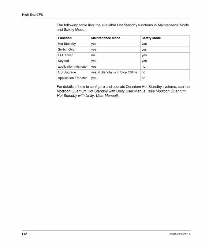
High End CPU
The following table lists the available Hot Standby functions in Maintenance Mode and Safety Mode:
For details of how to configure and operate Quantum Hot Standby systems, see the Modicon Quantum Hot Standby with Unity User Manual (see Modicon Quantum, Hot Standby with Unity, User Manual).
Function Maintenance Mode Safety Mode
Hot Standby yes yes
Switch Over yes yes
EFB Swap no yes
Keypad yes yes
application mismatch yes no
OS Upgrade yes, if Standby is in Stop Offline no
Application Transfer yes no
142 35010529 05/2010

High End CPU
Controls and Displays
Lens Cover
The protective lens cover can be opened by sliding upwards.
With the lens cover open you have access to the following items:key switchbatteryreset button
Key Switch
The key switch is a security feature and a memory protection switch. The key switch has two positions: locked and unlocked. The key switch is only read and deciphered by the PLC OS (executive) portion of the firmware and not by the OS loader portion.
The Quantum High End processor has a set of system menus that enable the operator to:
perform PLC operations (i.e., start PLC, stop PLC)display module parameters (i.e., communications parameters)switch to the maintenance mode (Safety processors)
The effect of the key position is shown below:
NOTE: For more explanations about Maintenance and Safe mode of Safety processors (see Modicon Quantum, Quantum Safety PLC, Safety Reference Manual)
Reset Button
When pressed, this button forces a cold start of the PLC.
Key Position
PLC Operation
unlocked: System menu operations can be invoked and changeable module parameters can be modified by the operator with the LCD and keypad.Memory protection is OFF.You can switch to Maintenance mode (Safety processors).
locked: No system menu operations can be invoked and module parameters are read-only.Memory protection is ON.Safe mode forced (Safety processors).
Switching the key switch position from locked to unlocked or vice versa turns on the LCD's backlight.
35010529 05/2010 143
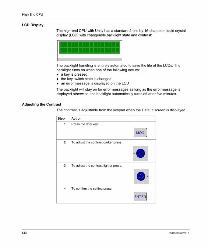
High End CPU
LCD Display
The high-end CPU with Unity has a standard 2-line by 16-character liquid crystal display (LCD) with changeable backlight state and contrast:
The backlight handling is entirely automated to save the life of the LCDs. The backlight turns on when one of the following occurs:
a key is pressedthe key switch state is changedan error message is displayed on the LCD
The backlight will stay on for error messages as long as the error message is displayed otherwise, the backlight automatically turns off after five minutes.
Adjusting the Contrast
The contrast is adjustable from the keypad when the Default screen is displayed.
Step Action
1 Press the MOD key:
2 To adjust the contrast darker press:
3 To adjust the contrast lighter press:
4 To confirm the setting press:
144 35010529 05/2010
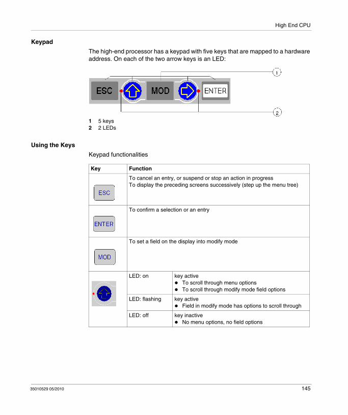
High End CPU
Keypad
The high-end processor has a keypad with five keys that are mapped to a hardware address. On each of the two arrow keys is an LED:
1 5 keys2 2 LEDs
Using the Keys
Keypad functionalities
Key Function
To cancel an entry, or suspend or stop an action in progressTo display the preceding screens successively (step up the menu tree)
To confirm a selection or an entry
To set a field on the display into modify mode
LED: on key activeTo scroll through menu optionsTo scroll through modify mode field options
LED: flashing key activeField in modify mode has options to scroll through
LED: off key inactiveNo menu options, no field options
35010529 05/2010 145
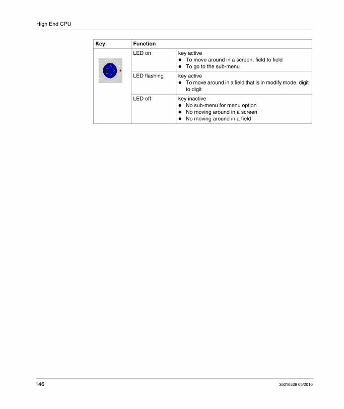
High End CPU
LED on key active To move around in a screen, field to field To go to the sub-menu
LED flashing key activeTo move around in a field that is in modify mode, digit to digit
LED off key inactiveNo sub-menu for menu optionNo moving around in a screenNo moving around in a field
Key Function
146 35010529 05/2010

High End CPU
Indicators
Overview
The High End processors use two types of indicators:1. LCD display: The Default Screen (see page 152) serves as a Controller status
screen.2. LED Indicators: The functionality of the LEDs is described in a table after the
figure.
The following figure shows the two types of indicators.
1 LCD Display (lens cover closed)2 LED Indicators
35010529 05/2010 147

High End CPU
LED Description
The following table shows the description for the LED indicators of the different High End CPU modules.
LEDs Indication
Standard Processors 140 CPU 65* *0 / 140 CPU 651 60S
Hot StandBy Processors 140 CPU 671 60 / 140 CPU 671 60S / 140 CPU 672 61
COM (yellow)
Controlled by the Coprocessor hardware
Indicates Ethernet activity
Controlled by the Coprocessor hardwareIndicates Primary or Standby activity
STS (yellow)
Controlled by the Coprocessor software
Controlled by the Coprocessor firmwareBlinking: system is redundant and data are exchanged from the Primary to Standby controllerON: system not redundant / Copro booting from power-on to end of self-testsOFF: Copro auto tests were not successfull
ON Normal
OFF Copro auto tests unsuccessful. Possible hardware problem.
Flashing:
1 Flash Configuration in progress. Temporary situation.
2 Flashes Invalid MAC address
3 Flashes Link not connected
4 Flashes Duplicate IP Address. Module is set to its default IP address.
5 Flashes Waiting for IP address from address server
6 Flashes Invalid IP address. Module is set to its default IP address.
7 Flashes Firmware incompatibility between PLC OS and Copro firmware
148 35010529 05/2010

High End CPU
Modbus port
Overview
In front of the CPU the Modbus port is of type RJ45.
The network topology is determined by a protocol:
for RS-232, it’s a point to point topology,for RS-485, it’s a bus topology with processor as master.
Connections on RJ45 are different, according to selected protocol. In configuration window of a 140 CPU 6•• •• Quantum PLC, the protocol is selected in tab Port Modbus.
Pinouts
Illustration:
The table following presents the pinouts of RS-232 and RS485 protocols:
NOTE: For RS-485 protocol pins 1 and 6 must be short circuited as well as pins 2 and 3.
Pin RS-232 Signal RS-485 Signal
1 DTR D-
2 DSR D+
3 TxD
4 RxD Not used
5 GND GND
6 RTS
7 CTS Not used
8 GND (optional) GND (optional)
35010529 05/2010 149

High End CPU
RS232/RJ45 adapter
To connect PC-AT computers that have a 9-pin RS-232 port to the 8-pin RJ45 Modbus port on the 140 CPU 651 •0 and 140 CPU 671 60, you must connect the 110 XCA 020 300 adapter (9-pin/RJ45) on the PC with the straight 110 XCA 28 202 cable (8-pin RJ45 to 8-pin RJ45).
The following figures show the 9-pin adapter front view (left) and side view (right).
Connector Pinouts Figure
The following figure shows the 9-pin RJ45 connector schematic.
150 35010529 05/2010

High End CPU
Using the LCD Display Screens
Overview
The controller’s LCD displays messages. These messages indicate the controller’s status. There are four levels of menus and submenus. Menus are accessed using the keypad (see page 145) on the front of the controller.
For detailed information about the menus and submenus see:PLC Operations Menus and Submenus (see page 154)Using the Communications Menus and Submenus (see page 157)Using the LCD Settings Menus and Submenus (see page 159)Using the System Info Menus and Submenus (see page 160)
Structure: LCD display menus and submenus
1 Default Screen2 System Menus3 Sub Menus4 Sub Screens
35010529 05/2010 151
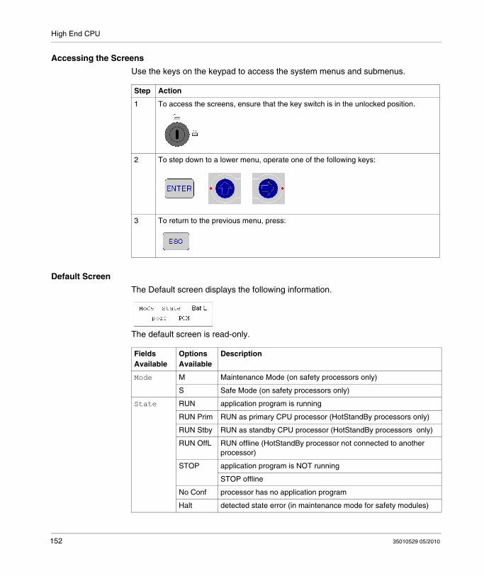
High End CPU
Accessing the Screens
Use the keys on the keypad to access the system menus and submenus.
Default Screen
The Default screen displays the following information.
The default screen is read-only.
Step Action
1 To access the screens, ensure that the key switch is in the unlocked position.
2 To step down to a lower menu, operate one of the following keys:
3 To return to the previous menu, press:
Fields Available
Options Available
Description
Mode M Maintenance Mode (on safety processors only)
S Safe Mode (on safety processors only)
State RUN application program is running
RUN Prim RUN as primary CPU processor (HotStandBy processors only)
RUN Stby RUN as standby CPU processor (HotStandBy processors only)
RUN OffL RUN offline (HotStandBy processor not connected to another processor)
STOP application program is NOT running
STOP offline
No Conf processor has no application program
Halt detected state error (in maintenance mode for safety modules)
152 35010529 05/2010
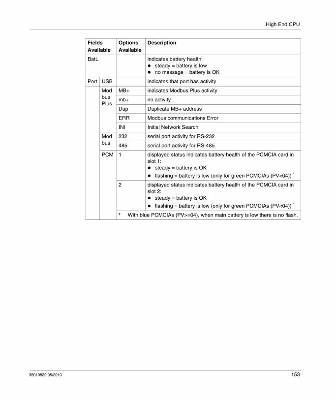
High End CPU
BatL indicates battery health:steady = battery is lowno message = battery is OK
Port USB indicates that port has activity
Modbus Plus
MB+ indicates Modbus Plus activity
mb+ no activity
Dup Duplicate MB+ address
ERR Modbus communications Error
INI Initial Network Search
Modbus
232 serial port activity for RS-232
485 serial port activity for RS-485
PCM 1 displayed status indicates battery health of the PCMCIA card in slot 1:
steady = battery is OK
flashing = battery is low (only for green PCMCIAs (PV<04)) *
2 displayed status indicates battery health of the PCMCIA card in slot 2:
steady = battery is OK
flashing = battery is low (only for green PCMCIAs (PV<04)) *
* With blue PCMCIAs (PV>=04), when main battery is low there is no flash.
Fields Available
Options Available
Description
35010529 05/2010 153
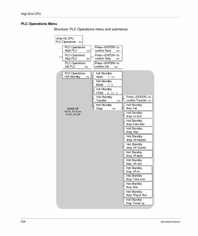
High End CPU
PLC Operations Menu
Structure: PLC Operations menu and submenus
154 35010529 05/2010

High End CPU
Submenu: PLC Operations: Start, Stop, Init
Submenu: PLC Operations Hot Standby CPU
Start, Stop, Init Screens Display
Fields Available Description
Start PLC Press <ENTER> to confirm Start Pressing <ENTER> starts the controller
Stop PLC Press <ENTER> to confirm Stop Pressing <ENTER> stops the controller
Init PLC Press <ENTER> to confirm Init Pressing <ENTER> initializes the controllerOn safety processors, this command is only available in maintenance mode
Screen Field Option Description
Hot Standby State:
Stateread only
PRIMARY CPU Controller serves as primary CPU unit
STANDBY CPU Controller serves as standby CPUunit
Offline Controller not connected to another
Hot Standby Mode:
Mode(modifiable only if the key switch is in the unlocked position)
RUN STS steady Controller is active and is either serving as primary CPU controller or able to take over the primary CPU role if needed
STS flashing
Controller is transferring/updating and when the transfer is done, RUN will stay on steady
OFFLINE STS steady Controller is taken out of service without stopping it or disconnecting it from powerIf the controller is the primary CPU unit when the Mode state is changed to OFFLINE, control switches to the standby CPU unit. If the standby CPU controller is taken OFFLINE, the primary CPU unit continues to operate without a backup
STS flashing
Controller is transferring/updating and when the transfer is done, OFFLINE will stay on steady
Hot Standby Order:
A or B(modifiable only if the key switch is in the unlocked position)
FIRST Hot Standby Power Order
SECOND
35010529 05/2010 155

High End CPU
Hot Standby Transfer:
-(this menu option is only enabled, if the key switch is in the unlocked position)
Pressing the <ENTER> key confirms the Transfer. The transfer will initiate the request of a program update from the primary CPU controller. Pressing any other key will cancel the Transfer initiation and returns the Hot Standby Transfer menu option screen to the display.
Hot Standby Diag:
Oder of diagnostic screen varies with the orperation.
Halt User’s task in halt mode
RIO fails Detected error reported by RIO head
HSBY fails Detected error reported by optical link
Stop Stop command ordered
Off keypad Offline commandentered on keypad
Off %SW60 Offline command set in command register
Off appli Offline due to application mismatch
Off vers Offline due to PLC or Copro OS mismatch
Off RIO Offline due to Remote IO error
Take over Standby CPU switched to primary CPU mode
Run Run command ordered
Plug & Run Standby CPU plugged and started
Power up PLC has just started, no message
Screen Field Option Description
156 35010529 05/2010
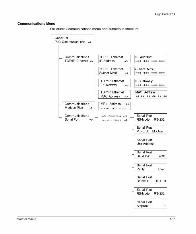
High End CPU
Communications Menu
Structure: Communications menu and submenus structure
35010529 05/2010 157
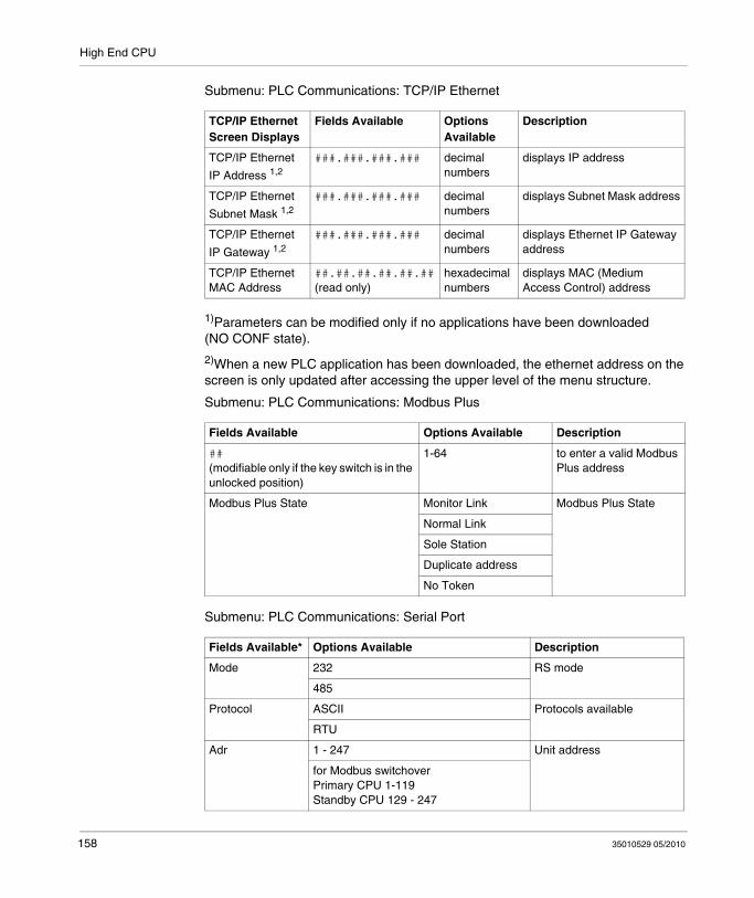
High End CPU
Submenu: PLC Communications: TCP/IP Ethernet
1)Parameters can be modified only if no applications have been downloaded (NO CONF state).
2)When a new PLC application has been downloaded, the ethernet address on the screen is only updated after accessing the upper level of the menu structure.
Submenu: PLC Communications: Modbus Plus
Submenu: PLC Communications: Serial Port
TCP/IP Ethernet Screen Displays
Fields Available Options Available
Description
TCP/IP Ethernet
IP Address 1,2###.###.###.### decimal
numbersdisplays IP address
TCP/IP Ethernet
Subnet Mask 1,2###.###.###.### decimal
numbersdisplays Subnet Mask address
TCP/IP Ethernet
IP Gateway 1,2###.###.###.### decimal
numbersdisplays Ethernet IP Gateway address
TCP/IP Ethernet MAC Address
##.##.##.##.##.##(read only)
hexadecimal numbers
displays MAC (Medium Access Control) address
Fields Available Options Available Description
##(modifiable only if the key switch is in the unlocked position)
1-64 to enter a valid Modbus Plus address
Modbus Plus State Monitor Link Modbus Plus State
Normal Link
Sole Station
Duplicate address
No Token
Fields Available* Options Available Description
Mode 232 RS mode
485
Protocol ASCII Protocols available
RTU
Adr 1 - 247 Unit address
for Modbus switchoverPrimary CPU 1-119Standby CPU 129 - 247
158 35010529 05/2010
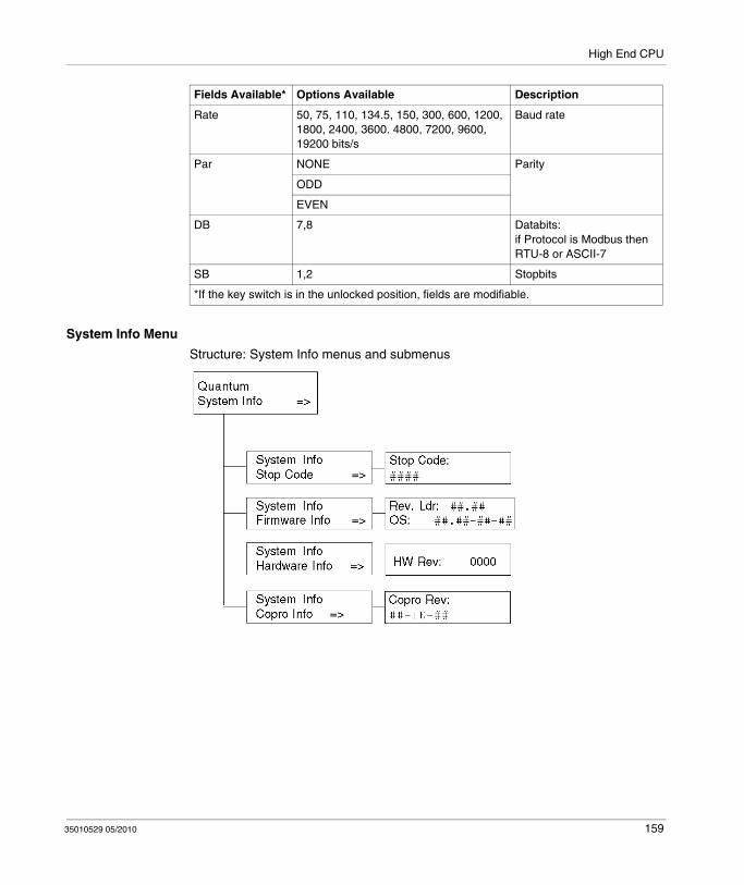
High End CPU
System Info Menu
Structure: System Info menus and submenus
Rate 50, 75, 110, 134.5, 150, 300, 600, 1200, 1800, 2400, 3600. 4800, 7200, 9600, 19200 bits/s
Baud rate
Par NONE Parity
ODD
EVEN
DB 7,8 Databits:if Protocol is Modbus then RTU-8 or ASCII-7
SB 1,2 Stopbits
*If the key switch is in the unlocked position, fields are modifiable.
Fields Available* Options Available Description
35010529 05/2010 159
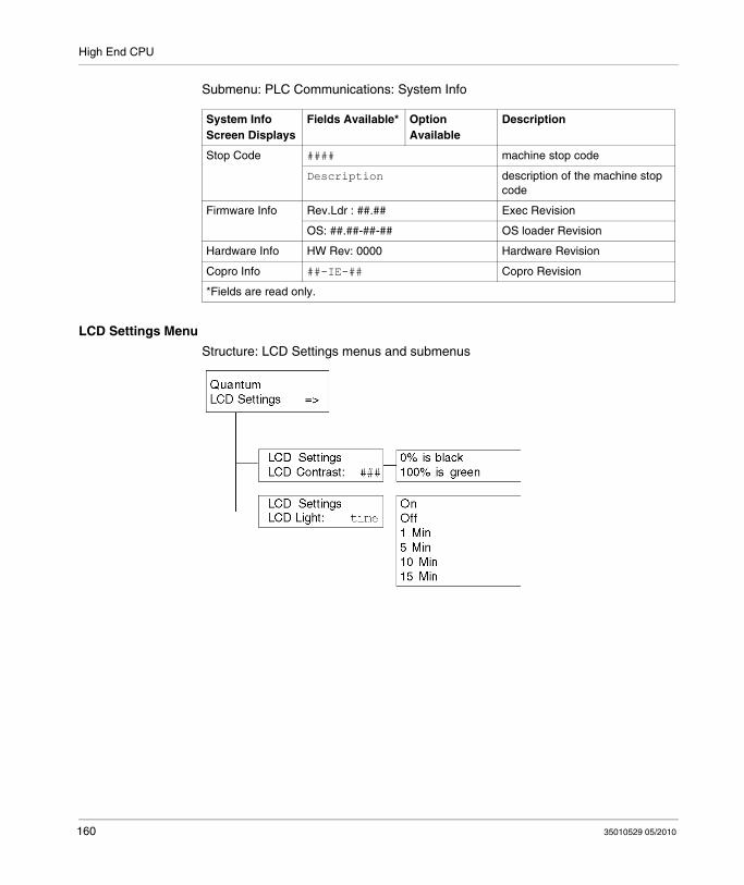
High End CPU
Submenu: PLC Communications: System Info
LCD Settings Menu
Structure: LCD Settings menus and submenus
System Info Screen Displays
Fields Available* Option Available
Description
Stop Code #### machine stop code
Description description of the machine stop code
Firmware Info Rev.Ldr : ##.## Exec Revision
OS: ##.##-##-## OS loader Revision
Hardware Info HW Rev: 0000 Hardware Revision
Copro Info ##-IE-## Copro Revision
*Fields are read only.
160 35010529 05/2010
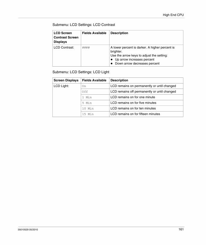
High End CPU
Submenu: LCD Settings: LCD Contrast
Submenu: LCD Settings: LCD Light
LCD Screen Contrast Screen Displays
Fields Available Description
LCD Contrast: #### A lower percent is darker. A higher percent is brighter.Use the arrow keys to adjust the setting:
Up arrow increases percentDown arrow decreases percent
Screen Displays Fields Available Description
LCD Light: On LCD remains on permanently or until changed
Off LCD remains off permanently or until changed
1 Min LCD remains on for one minute
5 Min LCD remains on for five minutes
10 Min LCD remains on for ten minutes
15 Min LCD remains on for fifteen minutes
35010529 05/2010 161

High End CPU
Processor Configuration Screen
Accessing with Unity Pro
After starting Unity Pro, go to the Local Bus in the Structural View of the Project Browser.
Step Action
1 Double-click on Local Bus to open the Local Bus configuration editor .
2 Select the CPU module and right-click.The context menu appears.
162 35010529 05/2010

High End CPU
NOTE: %MWi will reset with the cold start %S0 or a loading program. Cold start is typically after a program load, %S0 can be set with the user program to initiate a cold start
3 Select Open Module.The editor appears.
4 Choose one of these tabs:OverviewSummary Configuration Quantum / (see Unity Pro, Operating Modes, ) Configuration Quantum Hot Standby PLCs / (see Modicon Quantum, Hot Standby with Unity, User Manual) Configuration Quantum Safety PLCs (see Unity Pro XLS Software, Operating Mode Manual, Safety PLC Specifics) Modbus Port Quantum / (see Unity Pro, Operating Modes, ) Modbus Port Quantum Hot Standby PLCs / (see Modicon Quantum, Hot Standby with Unity, User Manual) Modbus Quantum Safety PLCs (see Unity Pro, Operating Modes, )Animation Port Quantum / (see Unity Pro, Operating Modes, ) Animation Port Quantum Hot Standby PLCs / (see Modicon Quantum, Hot Standby with Unity, User Manual) Animation Quantum Safety PLCs (see Unity Pro XLS Software, Operating Mode Manual, Safety PLC Specifics) Hot StandbyFaultsI/O Objects
Step Action
35010529 05/2010 163
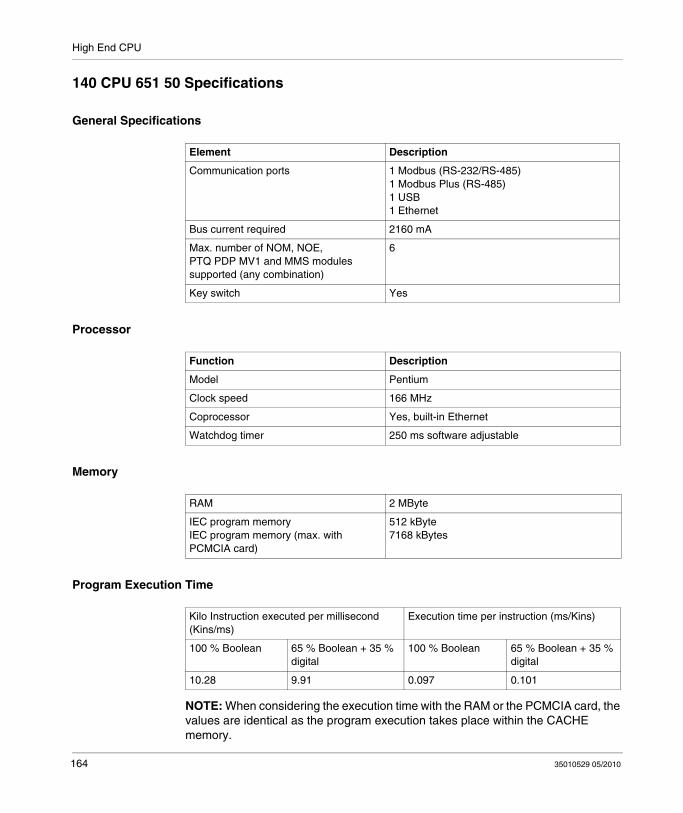
High End CPU
140 CPU 651 50 Specifications
General Specifications
Processor
Memory
Program Execution Time
NOTE: When considering the execution time with the RAM or the PCMCIA card, the values are identical as the program execution takes place within the CACHE memory.
Element Description
Communication ports 1 Modbus (RS-232/RS-485)1 Modbus Plus (RS-485)1 USB1 Ethernet
Bus current required 2160 mA
Max. number of NOM, NOE, PTQ PDP MV1 and MMS modules supported (any combination)
6
Key switch Yes
Function Description
Model Pentium
Clock speed 166 MHz
Coprocessor Yes, built-in Ethernet
Watchdog timer 250 ms software adjustable
RAM 2 MByte
IEC program memoryIEC program memory (max. with PCMCIA card)
512 kByte7168 kBytes
Kilo Instruction executed per millisecond (Kins/ms)
Execution time per instruction (ms/Kins)
100 % Boolean 65 % Boolean + 35 % digital
100 % Boolean 65 % Boolean + 35 % digital
10.28 9.91 0.097 0.101
164 35010529 05/2010

High End CPU
Reference Capacity
Local I/O
Remote I/O
Distributed I/O
Battery and Clock
Discrete (bits) 64 kByte (any combination)
Registers (words) 64 kByte max.
Max. I/O words 1024 bits/module with no limit on total Local I/O words
Max. I/O words/drop 64 in / 64 out*
Max. number of remote drops 31
* This information can be a mix of discrete or register I/O. For each word of configured I/O, one of the I/O words must be subtracted from the total available.
Number of networks per system 1 (3**)
Max. words per network 500 in / 500 outFor every DIO drop, there is a minimum of two words input of overhead
Max. words per Node 30 in / 32 out
Max. number of DIO Drops per Network 64
** Requires the use of the 140 NOM 21• 00 option module.
Type 3 V lithium
Service Life 1200 mAh
Shelf life 10 years with 0.5% loss of capacity/year
Battery load current @ power-off typical: 14 μA
max. 420 μA
TOD clock +/-8.0 seconds/day @ 0 ... 60 ° C
35010529 05/2010 165

High End CPU
Diagnostics
Power-up RAMRAM addressExecutive ChecksumUser Logic CheckProcessor
Run Time RAMRAM addressExecutive ChecksumUser Logic Check
166 35010529 05/2010

High End CPU
140 CPU 651 60 Specifications
General Specifications
Processor
Memory
Program Execution Time
NOTE: When considering the execution time with the RAM or the PCMCIA card, the values are identical as the program execution takes place within the CACHE memory.
Element Description
Communication ports 1 Modbus (RS-232/RS-485)1 Modbus Plus (RS-485)1 USB1 Ethernet
Bus current required 2760 mA
Max. number of NOM, NOE, PTQ PDP MV1 and MMS modules supported (any combination)
6
Key switch Yes
Function Description
Model Pentium
Clock speed 266 MHz
Coprocessor Yes, built-in Ethernet
Watchdog timer 250 ms software adjustable
RAM 2 MByte
IEC program memoryIEC program memory (max. with PCMCIA card)
1024 kByte7168 kBytes
Kilo Instruction executed per millisecond (Kins/ms)
Execution time per instruction (ms/Kins)
100 % Boolean 65 % Boolean + 35 % digital
100 % Boolean 65 % Boolean + 35 % digital
10.28 10.07 0.097 0.099
35010529 05/2010 167

High End CPU
Reference Capacity
Local I/O
Remote I/O
Distributed I/O
Battery and Clock
Discrete (bits) 64 kByte (any combination)
Registers (words) 64 kByte max.
Max. I/O words 1024 bits/module with no limit on total LIO words
Max. I/O words/drop 64 in / 64 out*
Max. number of remote drops 31
* This information can be a mix of discrete or register I/O. For each word of configured I/O, one of the I/O words must be subtracted from the total available.
Number of networks per system 1 (3**)
Max. words per network 500 in / 500 outFor every DIO drop, there is a minimum of two words input of overhead
Max. words/node 30 in / 32 out
Max. number of DIO drops/network 64
** Requires the use of the 140 NOM 21• 00 option module.
Type 3 V lithium
Service life 1200 mAh
Shelf life 10 years with 0.5% loss of capacity/year
Battery load current @ power-off typical: 14 μA
max. 420 μA
TOD clock +/-8.0 seconds/day @ 0 ... 60 ° C
168 35010529 05/2010
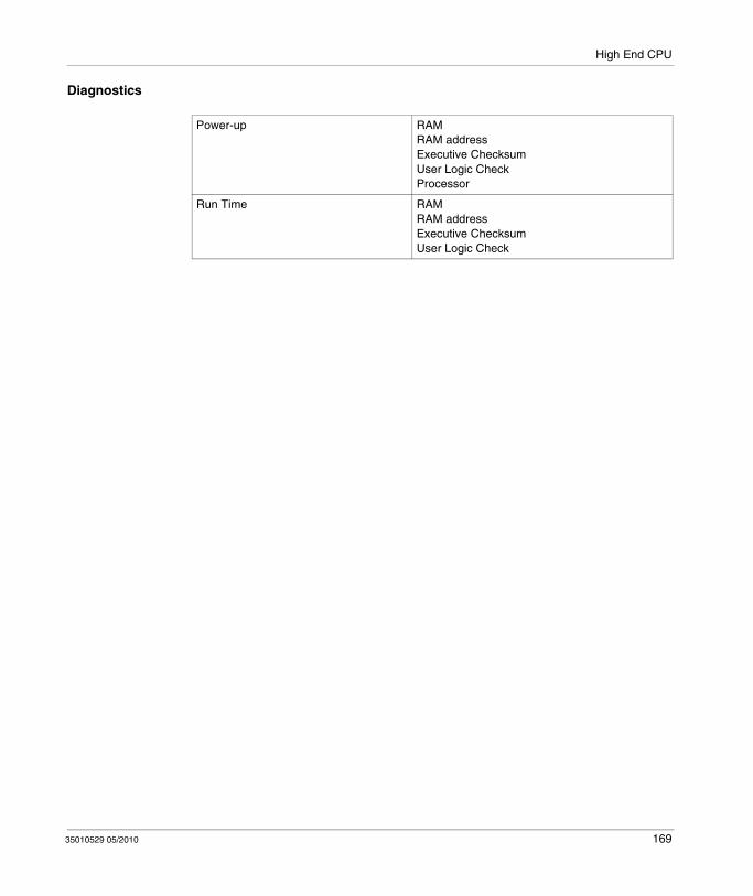
High End CPU
Diagnostics
Power-up RAMRAM addressExecutive ChecksumUser Logic CheckProcessor
Run Time RAMRAM addressExecutive ChecksumUser Logic Check
35010529 05/2010 169

High End CPU
140 CPU 651 60S Specifications
General Specifications
Processor
Memory
Reference Capacity
Local I/O
Communication ports 1 Modbus (RS-232/RS-485)1 Modbus Plus (RS-485)1 USB1 Ethernet
Bus current required 2760 mA
Max. number of NOE 771 11 and PTQ PDP MV1 modules supported
6
Key switch Yes
Model Pentium
Clock speed 266 MHz
Coprocessor Yes, built-in Ethernet
Watchdog timer 250 ms software adjustable
RAM 2 MByte
IEC program memoryIEC program memory (max. with PCMCIA card)
1024 kByte7168 kBytes
Discrete (bits) 64 kByte (any combination)
Registers (words) 64 kByte max.
Max. I/O words 1024 bits/module with no limit on total LIO words
170 35010529 05/2010

High End CPU
Remote I/O
Battery and Clock
Diagnostics
Max. I/O words/drop 64 in / 64 out*
Max. number of remote drops 31
* This information can be a mix of discrete or register I/O. For each word of configured I/O, one of the I/O words must be subtracted from the total available.
Type 3 V lithium
Service life 1200 mAh
Shelf life 10 years with 0.5% loss of capacity/year
Battery load current @ power-off typical: 14 μA
max. 420 μA
TOD clock +/-8.0 seconds/day @ 0 ... 60 ° C
Power-up & Run Time RAMRAM addressExecutive CRCUser Logic CheckProcessorsClock
35010529 05/2010 171

High End CPU
140 CPU 652 60 Specifications
General Specifications
Processor
Memory
Reference Capacity
Local I/O
Element Description
Communication ports 1 Modbus (RS-232/RS-485)1 Modbus Plus (RS-485)1 USB1 Ethernet
Bus current required 2760 mA
Max. number of NOM, NOE, PTQ PDP MV1 and MMS modules supported (any combination)
6
Key switch Yes
Function Description
Model Pentium
Clock speed 266 MHz
Coprocessor Yes, built-in Ethernet
Watchdog timer 250 ms software adjustable
RAM 4 MByte
IEC program memoryIEC program memory (max. with PCMCIA card)
3072 kByte7168 kBytes
Discrete (bits) 64 kByte (any combination)
Registers (words) 64 kByte max.
Max. I/O words 1024 bits/module with no limit on total LIO words
172 35010529 05/2010

High End CPU
Remote I/O
Distributed I/O
Battery and Clock
Diagnostics
Max. I/O words/drop 64 in / 64 out*
Max. number of remote drops 31
* This information can be a mix of discrete or register I/O. For each word of configured I/O, one of the I/O words must be subtracted from the total available.
Number of networks per system 1 (3**)
Max. words per network 500 in / 500 outFor every DIO drop, there is a minimum of two words input of overhead
Max. words/node 30 in / 32 out
Max. number of DIO drops/network 64
** Requires the use of the 140 NOM 21• 00 option module.
Type 3 V lithium
Service life 1200 mAh
Shelf life 10 years with 0.5% loss of capacity/year
Battery load current @ power-off typical: 14 μA
max. 420 μA
TOD clock +/-8.0 seconds/day @ 0 ... 60 ° C
Power-up RAMRAM addressExecutive ChecksumUser Logic CheckProcessor
Run Time RAMRAM addressExecutive ChecksumUser Logic Check
35010529 05/2010 173

High End CPU
140 CPU 671 60 Specifications
Module Specifications
Processor
Memory
Element Description
Communication ports 1 Modbus (RS-232/RS-485)1 Modbus Plus (RS-485)1 USB1 Ethernet (used as HSBY port)
Bus current required 2.5 A
Max. number of NOM, NOE, PTQ PDP MV1 and MMS modules supported (any combination)
6
Key switch Yes
Keypad Yes
Function Description
Model Pentium
Clock speed 266 MHz
Coprocessor Yes, Built-in Ethernet
Watchdog timer 250 ms software adjustable
RAM 2 MByte
IEC program memory (and/or application data and configurationIEC program memory (max. with PCMCIA card)
1024 kByte7168 kBytes
174 35010529 05/2010

High End CPU
Program Execution Time
NOTE: When considering the execution time with the RAM or the PCMCIA card, the values are identical as the program execution takes place within the CACHE memory.
Reference Capacity
Remote I/O
Battery and Clock
Kilo Instruction executed per millisecond (Kins/ms)
Execution time per instruction (ms/Kins)
100 % Boolean 65 % Boolean + 35 % digital
100 % Boolean 65 % Boolean + 35 % digital
10.28 10.07 0.097 0.099
Discrete (bits) 64 k (any combination)
Registers (words) 64 k max.
Max. I/O words/drop 64 in / 64 out*
Max. number of remote drops 31
* This information can be a mix of discrete or register I/O. For each word of configured I/O, one of the I/O words must be subtracted from the total available.
Battery type 3 V Lithium
Service life 1.2 Ah
Shelf life 10 years with 0.5% loss of capacity/year
Battery load current @ power-off typical: 14 μA
max. 420 μA
TOD clock +/-8.0 s/day @ 0 ... 60 ° C
35010529 05/2010 175

High End CPU
Diagnostic
Power-up RAMRAM addressExecutive ChecksumUser Logic CheckProcessor
Run Time RAMRAM addressExecutive ChecksumUser Logic Check
176 35010529 05/2010

High End CPU
140 CPU 671 60S Specifications
Module Specifications
Processor
Memory
Reference Capacity
Component Description
Communication ports 1 Modbus (RS-232/RS-485)1 Modbus Plus (RS-485)1 USB1 Ethernet (used as HSBY port)
Bus current required 2.5 A
Max. number of NOE 771 11 modules supported
6
Key switch Yes
Keypad Yes
Feature Description
Model Pentium
Clock speed 266 MHz
Coprocessor Yes, Built-in Ethernet
Watchdog timer 250 ms software adjustable
RAM 4 MByte
IEC program memory (and/or application data and configuration)IEC program memory (max. with PCMCIA card)
1024 kByte7168 kBytes
Discrete (bits) 64 k (any combination)
Registers (words) 64 k max.
35010529 05/2010 177

High End CPU
Remote I/O
Battery and Clock
Diagnostic
Max. I/O words/drop 64 in / 64 out*
Max. number of remote drops 31
* This information can be a mix of discrete or register I/O. For each word of configured I/O, one of the I/O words must be subtracted from the total available.
Battery type 3 V Lithium
Service life 1.2 Ah
Shelf life 10 years with 0.5% loss of capacity/year
Battery load current @ power-off typical: 14 μA
max. 420 μA
TOD clock +/-8.0 s/day @ 0 ... 60 ° C
Power-up RAMRAM addressExecutive ChecksumUser Logic CheckProcessor
Run Time RAMRAM addressExecutive ChecksumUser Logic Check
178 35010529 05/2010
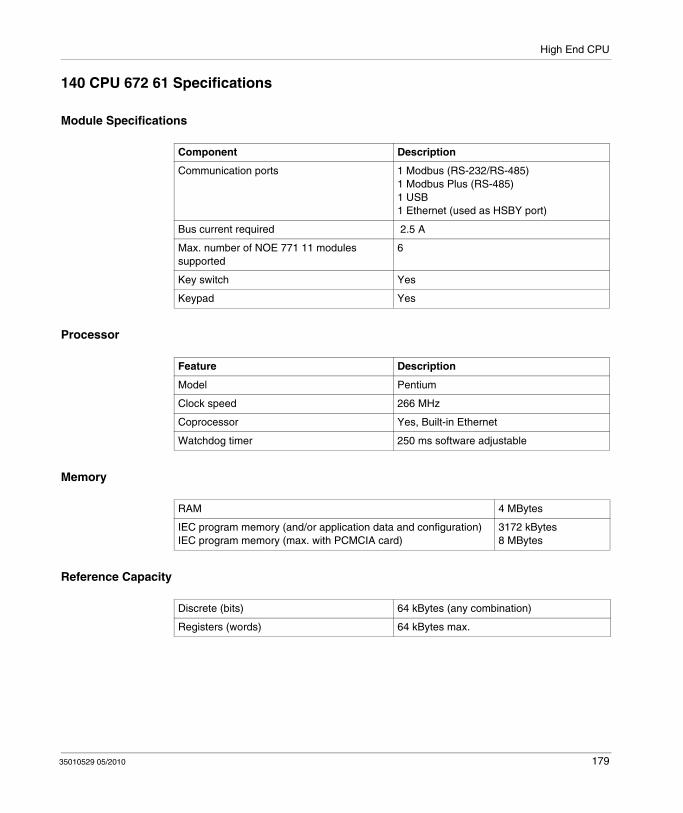
High End CPU
140 CPU 672 61 Specifications
Module Specifications
Processor
Memory
Reference Capacity
Component Description
Communication ports 1 Modbus (RS-232/RS-485)1 Modbus Plus (RS-485)1 USB1 Ethernet (used as HSBY port)
Bus current required 2.5 A
Max. number of NOE 771 11 modules supported
6
Key switch Yes
Keypad Yes
Feature Description
Model Pentium
Clock speed 266 MHz
Coprocessor Yes, Built-in Ethernet
Watchdog timer 250 ms software adjustable
RAM 4 MBytes
IEC program memory (and/or application data and configuration)IEC program memory (max. with PCMCIA card)
3172 kBytes8 MBytes
Discrete (bits) 64 kBytes (any combination)
Registers (words) 64 kBytes max.
35010529 05/2010 179
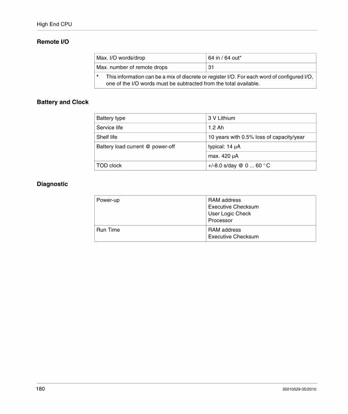
High End CPU
Remote I/O
Battery and Clock
Diagnostic
Max. I/O words/drop 64 in / 64 out*
Max. number of remote drops 31
* This information can be a mix of discrete or register I/O. For each word of configured I/O, one of the I/O words must be subtracted from the total available.
Battery type 3 V Lithium
Service life 1.2 Ah
Shelf life 10 years with 0.5% loss of capacity/year
Battery load current @ power-off typical: 14 μA
max. 420 μA
TOD clock +/-8.0 s/day @ 0 ... 60 ° C
Power-up RAM addressExecutive ChecksumUser Logic CheckProcessor
Run Time RAM addressExecutive Checksum
180 35010529 05/2010
35010529 05/2010
10
Memory Cards for High End CPU
35010529 05/2010
Memory Cards for High End CPU
Purpose
This chapter provides information on the memory cards for High End Controller modules.
What's in this Chapter?
This chapter contains the following topics:
Topic Page
Memory Cards for High End CPUs 182
Installing/Extracting PCMCIA Extension Cards on Advanced Quantum Processors
185
Changing the Batteries of a PCMCIA Memory Card 188
Battery Lifetimes for the PCMCIA Memory Card 192
181
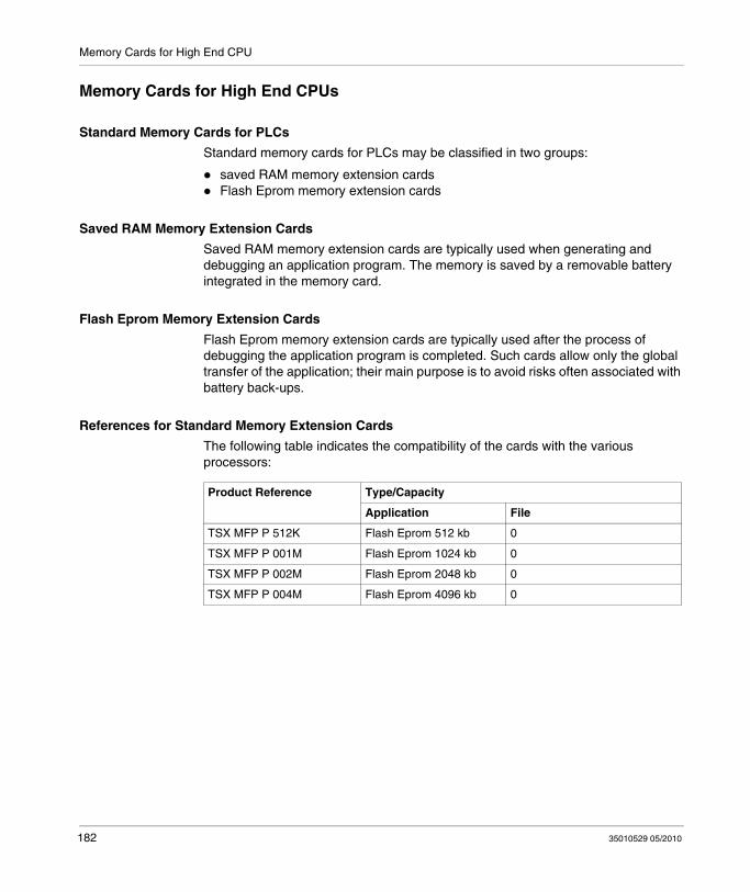
Memory Cards for High End CPU
Memory Cards for High End CPUs
Standard Memory Cards for PLCs
Standard memory cards for PLCs may be classified in two groups:
saved RAM memory extension cardsFlash Eprom memory extension cards
Saved RAM Memory Extension Cards
Saved RAM memory extension cards are typically used when generating and debugging an application program. The memory is saved by a removable battery integrated in the memory card.
Flash Eprom Memory Extension Cards
Flash Eprom memory extension cards are typically used after the process of debugging the application program is completed. Such cards allow only the global transfer of the application; their main purpose is to avoid risks often associated with battery back-ups.
References for Standard Memory Extension Cards
The following table indicates the compatibility of the cards with the various processors:
Product Reference Type/Capacity
Application File
TSX MFP P 512K Flash Eprom 512 kb 0
TSX MFP P 001M Flash Eprom 1024 kb 0
TSX MFP P 002M Flash Eprom 2048 kb 0
TSX MFP P 004M Flash Eprom 4096 kb 0
182 35010529 05/2010

Memory Cards for High End CPU
Application + Files Type Memory Extension Cards
In addition to the conventional application storage area (program + constants), these memory cards also maintain a file area used by the program to archive and/or restore data. Here are two sample applications:
automatic storage of application data and remote consultation via modemstorage of manufacturing formulas.
There are two types of memory cards:
Saved RAM memory extension cards: application + files. The memory is saved by a removable battery built into the memory card.Flash Eprom memory extension cards: application + files. In this instance, the data storage area is maintained in saved RAM, which implies that this type of card must be equipped with a back-up battery.
Card Reference Numbers
The following table provides the card reference numbers for the applications + file-type memory extension card, and the compatibility of these cards with the processors:
Product reference Technology Capacity
Application area File area (RAM type)
TSX MRP C 768K (1) RAM 768 kb
192 to 768 kb 0 to 576 kb
TSX MRP C 001M (1) RAM 1024 kb
192 to 1024 kb 0 to 832 kb
TSX MRP C 001M7 (1) RAM 1792 kb
192 to 1792 kb 0 to 1600 kb
TSX MRP C 002M (1) RAM 2048 kb
192 to 2048 kb 0 to 1856 kb
TSX MRP C 003M (1) RAM 3072 kb
192 to 3072 kb 0 to 2880 kb
TSX MRP C 007M (1) RAM 7168 kb
192 to 7168kb 0 to 6976 kb
TSX MCP C 512K Flash Eprom 512 kb 512 kb
TSX MCP C 001M Flash Eprom 1024 kb 512 kb
TSX MCP C 002M Flash Eprom 2048 kb 1024 kb
TSX MCP C 004M Flash Eprom 4096 kb 2048 kb
(1) PCMCIA having their applications memory areas and floating capacity and unfrozen files
35010529 05/2010 183
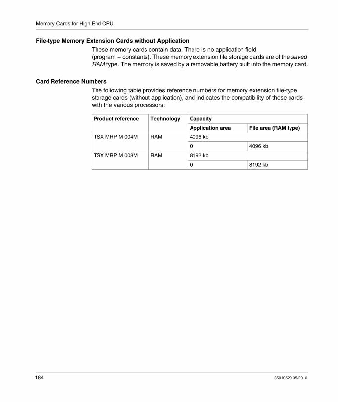
Memory Cards for High End CPU
File-type Memory Extension Cards without Application
These memory cards contain data. There is no application field (program + constants). These memory extension file storage cards are of the saved RAM type. The memory is saved by a removable battery built into the memory card.
Card Reference Numbers
The following table provides reference numbers for memory extension file-type storage cards (without application), and indicates the compatibility of these cards with the various processors:
Product reference Technology Capacity
Application area File area (RAM type)
TSX MRP M 004M RAM 4096 kb
0 4096 kb
TSX MRP M 008M RAM 8192 kb
0 8192 kb
184 35010529 05/2010
Memory Cards for High End CPU
Installing/Extracting PCMCIA Extension Cards on Advanced Quantum Processors
Overview
Memory Cards Located in Slot A (Top)
The extraction (or absence) of the cover, or of a data- or file-type memory card and case has no effect on PLC operations. In this case, the read/write functions of the memory card indicate an error if the application is in RUN mode.
The extraction of the application-type memory card and the card case causes the PLC to stop without saving the application context. In this case, the module outputs change to fallback mode. Inserting the case and the memory card containing the application causes a cold start.
WARNINGUNINTENDED EQUIPMENT OPERATION
Ensure that the protective cover is closed when the processor is running to maintain enclosure environmental ratings.
Failure to follow these instructions can result in death, serious injury, or equipment damage.
WARNINGUNINTENDED EQUIPMENT OPERATION
Ensure that the right user application is contained in the memory card before inserting it into the PLC. If the application contained in the memory card includes the RUN AUTO option, then the PLC will automatically restart in RUN mode with this application as soon as the inserted memory card content is restored to the PLC.
Failure to follow these instructions can result in death, serious injury, or equipment damage.
35010529 05/2010 185
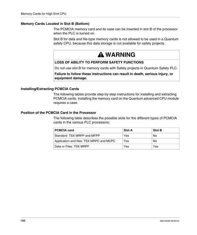
Memory Cards for High End CPU
Memory Cards Located in Slot B (Bottom)
The PCMCIA memory card and its case can be inserted in slot B of the processor when the PLC is turned on.
Slot B for data and file-type memory cards is not allowed to be used in a Quantum safety CPU, because this data storage is not available for safety projects.
Installing/Extracting PCMCIA Cards
The following tables provide step-by-step instructions for installing and extracting PCMCIA cards. Installing the memory card on the Quantum advanced CPU module requires a case.
Position of the PCMCIA Card in the Processor
The following table describes the possible slots for the different types of PCMCIA cards in the various PLC processors:
WARNINGLOSS OF ABILITY TO PERFORM SAFETY FUNCTIONS
Do not use slot B for memory cards with Safety projects in Quantum Safety PLC.
Failure to follow these instructions can result in death, serious injury, or equipment damage.
PCMCIA card Slot A Slot B
Standard: TSX MRPP and MFPP Yes No
Application and files: TSX MRPC and MCPC Yes No
Data or Files: TSX MRPF Yes Yes
186 35010529 05/2010

Memory Cards for High End CPU
Installing the Card in the Case
The following steps are to be performed regardless of the PCMCIA card type:
Installing the Card in the PLC
Before installing the card, note that if the program contained in the PCMCIA memory card includes the RUN AUTO option, the processor will automatically restart in RUN mode immediately after the card is inserted. Carry out the following steps to install the memory card into the processor:
Step Action Illustration
1 Position the memory card in the case at an oblique angle using the two attachment tabs.
2 Fully insert the memory card in the case. Now the card is solidly attached to the case.
Step Action
1 To remove the protective cover, unlock it and then remove it from the PLC.
2 Place the PCMCIA card/case assembly in the open slot. Fully insert the card/case assembly, then press lightly on the case to connect the card.
35010529 05/2010 187

Memory Cards for High End CPU
Changing the Batteries of a PCMCIA Memory Card
General Points
Memory cards:TSX MRP P• standard RAMTSX MRP C• RAM for files and application and TSX MCP C• Flash EPROM TSX MRP F• data and file-type
have 2 backup batteries, TSX BAT M02 (main) and TSX BAT M03 (auxiliary), which need to be changed periodically.
Two methods are possible: one is preventive, based on a periodic change of batteries, without first checking their status,the other is predictive, based on the signal sent by a system but, but is only possible for certain memory cards.
Preventive Method
This method is valid for memory cards versions and the PLCs that use those cards. Change both batteries according to the PV of the PCMCIA card, the PLC use, and the lifetime of batteries (see page 192). It does not matter which battery you change first: the application is preserved by the memory card. For the operate mode for changing the batteries: see the service instructions provided with the memory cards.
NOTE:
Batteries must not be removed from their positions simultaneously. One battery backs up the data and applications while the other is being replaced.Install the batteries as shown in the following diagrams, noting the correct polarity (+ and -)the memory card must not exceed 24 hours without its main battery in working order,to save the auxiliary batteries, you can replace them every 1.5 years. In this case, the maintenance procedure is a bit more complex, because for some memory cards you must remember to change the auxiliary battery only one time out of 3.the service lives shown above were calculated for the most unfavorable case: ambient temperature around the PLC at 60° C, and the PLC switched on for 21% of the time in the year (which corresponds to an 8 hour rotation per day with 30 maintenance stoppage days per year).
188 35010529 05/2010

Memory Cards for High End CPU
Predictive Method
This is maintenance based on using bits %S67 and %S75 and using the PCMCIA indicator on the Quantum interface. This method assumes that the auxiliary battery is changed preventively every 1.5 years. It is only possible:
on the PV06 small and medium capacity RAM memory cards (product version written on the card label), i.e. offering memory under Unity ≤ 768K (TSX MRP P •••K, TSX MCP C •••K, TSX MRP C 448K, TSX MRP C 768K),with Unity Pro ≥ 2.02,if the memory card is installed in the upper or lower PCMCIA slot on Quantum processors (140 CPU 671 60, 140 CPU 672 61, 140 CPU 651 60, 140 CPU 652 60 and 140 CPU 651 50).
When system bit %S67 (card in the top slot) or %S75 (card in the bottom slot) changes to 1 or the PCMCIA indicator on the processor interface flashes, it means that the main battery is weak. You have 8 days to replace the battery, as shown in the following tables.
NOTE: Before turning on the PLC or removing the memory card, save the project in Unity Pro. If the PLC must be left off or if the memory card must be outside the PLC for more than 8 days, and you have exceeded the service life of the main battery, then back up the application in Unity Pro.
Changing the Batteries
Carry out the following steps:
Step Action
1 Take the card out of its slot (see Premium and Atrium using Unity Pro, Processors, racks and power supply modules, Implementation manual).
2 Separate the PCMCIA card (see Premium and Atrium using Unity Pro, Processors, racks and power supply modules, Implementation manual) from its clip (or caddy).
3 Hold the PCMCIA card so you can access the battery slot. This is at the end of the card without the connector.
4 Replacement of the TSX BAT M02 battery: see table 1.Replacement of the TSX BAT M03 battery: see table 2.
5 Attach the PCMCIA card (see Premium and Atrium using Unity Pro, Processors, racks and power supply modules, Implementation manual) to its clip (or caddy).
6 Place the card back in the PLC. (see Premium and Atrium using Unity Pro, Processors, racks and power supply modules, Implementation manual)
35010529 05/2010 189

Memory Cards for High End CPU
Procedure for the TSX BAT M02 Battery:
Table 1
Step Action Illustration
1 Toggle the changeover lever toward the TSX BAT M02 (MAIN) battery in order to remove drawer from the main battery.
2 Remove the used battery from its holder:
3 Place the new battery in the holder, taking care to respect the polarity.
4 Insert the holder containing the battery in the card.
-+
- -++
+
190 35010529 05/2010

Memory Cards for High End CPU
Procedure for the TSX BAT M03 Battery:
Table 2
Step Action Illustration
1 Toggle the changeover lever toward the TSX BAT M03 (AUX) battery in order to remove drawer from the battery.
2 Remove the used battery from its holder:
3 Place the new battery in the holder, taking care to respect the polarity.
4 Insert the holder containing the battery in the card.
35010529 05/2010 191

Memory Cards for High End CPU
Battery Lifetimes for the PCMCIA Memory Card
Purpose
The purpose of this document is to give detailed information about the lifetime of batteries inside PCMCIA memory cards. The estimation of these lifetimes are based on data from component manufacturers.
Scope
The lifetime information is estimated for:
RAM PCMCIA memory cards,The three different cases of Product Version (PV): PV1/2/3, PV4/5 and PV6,Four ambient temperatures for the PLC location: 25° C / 40° C / 50° C / 60° C,Four different usage cases of the PCMCIAs: 100%, 92%, 66% and 33% of PLC power-up time. These values are for the following customer configurations:
100%: PLC powered up all year long or during 51 weeks,92%: PLC powered up all year long except during one month of maintenance,66%: PLC powered up all year long except during all weekends plus one month of maintenance,33%: PLC powered up all year long 12 hours a day, except during all weekends plus one month of maintenance.
A Min (minimum) and a Typical lifetime value:The Min value comes from the most unfavorable characteristics given by the component manufacturers. The actual observed lifetime will be greater than this value.The typical value comes from the typical characteristics of the component.
Main Battery Lifetime of PV1/2/3 PCMCIA (in Years)
The table below presents the lifetime of main battery TSX BAT M01(PV1/2/3) for PCMCIA memory cards:
PV1/2/3 For a 25° C PLC ambient temperature
100% powered up 92% PU (30d maint. 66% PU (WE. 30d maint.
33% PU (12h.WE. 30d maint.
Typical Min Typical Min Typical Min Typical Min
TSX MCP C 224K 7.10 7.10 6.71 5.58 5.77 3.36 4.82 2.20
TSX MCP C 512K 7.10 7.10 6.71 5.65 5.77 3.46 4.82 2.28
TSX MCP C 002M 7.10 7.10 6.29 3.82 4.66 1.57 3.45 0.88
TSX MRP P128K 7.10 7.10 6.71 5.58 5.77 3.36 4.82 2.20
TSX MRP P224K 7.10 7.10 6.71 5.65 5.77 3.46 4.82 2.28
TSX MRP P384K 7.10 7.10 6.71 4.99 5.77 2.60 4.82 1.59
192 35010529 05/2010
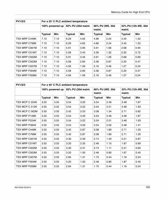
Memory Cards for High End CPU
TSX MRP C448K 7.10 7.10 6.29 4.65 4.66 2.24 3.45 1.33
TSX MRP C768K 7.10 7.10 6.29 4.65 4.66 2.24 3.45 1.33
TSX MRP C001M 7.10 7.10 5.91 3.95 3.91 1.66 2.68 0.94
TSX MRP C01M7 7.10 7.10 5.58 3.43 3.36 1.32 2.20 0.72
TSX MRP C002M 7.10 7.10 5.91 3.34 3.91 1.26 2.68 0.69
TSX MRP C003M 7.10 7.10 5.58 2.60 3.36 0.87 2.20 0.47
TSX MRP C007M 7.10 7.10 4.56 1.59 2.16 0.46 1.27 0.24
TSX MRP F004M 7.10 7.10 5.58 2.60 3.36 0.87 2.20 0.47
TSX MRP F008M 7.10 7.10 4.56 1.59 2.16 0.46 1.27 0.24
PV1/2/3 For a 25° C PLC ambient temperature
100% powered up 92% PU (30d maint. 66% PU (WE. 30d maint.
33% PU (12h.WE. 30d maint.
Typical Min Typical Min Typical Min Typical Min
PV1/2/3 For a 40° C PLC ambient temperature
100% powered up 92% PU (30d maint. 66% PU (WE. 30d maint.
33% PU (12h.WE. 30d maint.
Typical Min Typical Min Typical Min Typical Min
TSX MCP C 224K 3.55 3.55 3.54 3.20 3.54 2.46 3.48 1.87
TSX MCP C 512K 3.55 3.55 3.54 3.22 3.54 2.51 3.48 1.93
TSX MCP C 002M 3.55 3.55 3.42 2.53 3.08 1.34 2.71 0.82
TSX MRP P128K 3.55 3.55 3.54 3.20 3.54 2.46 3.48 1.87
TSX MRP P224K 3.55 3.55 3.54 3.22 3.54 2.51 3.48 1.93
TSX MRP P384K 3.55 3.55 3.54 3.00 3.54 2.02 3.48 1.41
TSX MRP C448K 3.55 3.55 3.42 2.87 3.08 1.80 2.71 1.20
TSX MRP C768K 3.55 3.55 3.42 2.87 3.08 1.80 2.71 1.20
TSX MRP C001M 3.55 3.55 3.30 2.59 2.74 1.40 2.21 0.87
TSX MRP C01M7 3.55 3.55 3.20 2.35 2.46 1.15 1.87 0.69
TSX MRP C002M 3.55 3.55 3.30 2.31 2.74 1.11 2.21 0.65
TSX MRP C003M 3.55 3.55 3.20 1.93 2.46 0.80 1.87 0.45
TSX MRP C007M 3.55 3.55 2.84 1.31 1.75 0.44 1.16 0.24
TSX MRP F004M 3.55 3.55 3.20 1.93 2.46 0.80 1.87 0.45
TSX MRP F008M 3.55 3.55 2.84 1.31 1.75 0.44 1.16 0.24
35010529 05/2010 193

Memory Cards for High End CPU
PV1/2/3 For a 50° C PLC ambient temperature
100% powered up 92% PU (30d maint. 66% PU (WE. 30d maint.
33% PU (12h.WE. 30d maint.
Typical Min Typical Min Typical Min Typical Min
TSX MCP C 224K 2.35 2.35 2.42 2.25 2.69 2.02 3.10 1.75
TSX MCP C 512K 2.35 2.35 2.42 2.26 2.69 2.05 3.10 1.81
TSX MCP C 002M 2.35 2.35 2.36 1.90 2.42 1.20 2.47 0.80
TSX MRP P128K 2.35 2.35 2.42 2.25 2.69 2.02 3.10 1.75
TSX MRP P224K 2.35 2.35 2.42 2.26 2.69 2.05 3.10 1.81
TSX MRP P384K 2.35 2.35 2.42 2.15 2.69 1.71 3.10 1.34
TSX MRP C448K 2.35 2.35 2.36 2.09 2.42 1.55 2.47 1.15
TSX MRP C768K 2.35 2.35 2.36 2.09 2.42 1.55 2.47 1.15
TSX MRP C001M 2.35 2.35 2.31 1.93 2.20 1.25 2.05 0.85
TSX MRP C01M7 2.35 2.35 2.25 1.80 2.02 1.04 1.75 0.67
TSX MRP C002M 2.35 2.35 2.31 1.77 2.20 1.01 2.05 0.64
TSX MRP C003M 2.35 2.35 2.25 1.54 2.02 0.75 1.75 0.44
TSX MRP C007M 2.35 2.35 2.07 1.12 1.51 0.42 1.11 0.23
TSX MRP F004M 2.35 2.35 2.25 1.54 2.02 0.75 1.75 0.44
TSX MRP F008M 2.35 2.35 2.07 1.12 1.51 0.42 1.11 0.23
PV1/2/3 For a 60° C PLC ambient temperature
100% powered up 92% PU (30d maint. 66% PU (WE. 30d maint.
33% PU (12h.WE. 30d maint.
Typical Min Typical Min Typical Min Typical Min
TSX MCP C 224K 1.57 1.57 1.63 1.56 1.91 1.54 2.40 1.50
TSX MCP C 512K 1.57 1.57 1.63 1.56 1.91 1.56 2.40 1.54
TSX MCP C 002M 1.57 1.57 1.61 1.38 1.77 1.01 2.00 0.74
TSX MRP P128K 1.57 1.57 1.63 1.56 1.91 1.54 2.40 1.50
TSX MRP P224K 1.57 1.57 1.63 1.56 1.91 1.56 2.40 1.54
TSX MRP P384K 1.57 1.57 1.63 1.51 1.91 1.36 2.40 1.19
TSX MRP C448K 1.57 1.57 1.61 1.47 1.77 1.25 2.00 1.04
194 35010529 05/2010

Memory Cards for High End CPU
Main Battery Lifetime of PV4/5 PCMCIA (in Years)
The table below presents the lifetime of main battery TSX BAT M02 (PV4/5) for PCMCIA memory cards:
TSX MRP C768K 1.57 1.57 1.61 1.47 1.77 1.25 2.00 1.04
TSX MRP C001M 1.57 1.57 1.58 1.40 1.65 1.05 1.72 0.78
TSX MRP C01M7 1.57 1.57 1.56 1.33 1.54 0.90 1.50 0.63
TSX MRP C002M 1.57 1.57 1.58 1.31 1.65 0.87 1.72 0.60
TSX MRP C003M 1.57 1.57 1.56 1.18 1.54 0.67 1.50 0.42
TSX MRP C007M 1.57 1.57 1.47 0.92 1.23 0.40 1.00 0.23
TSX MRP F004M 1.57 1.57 1.56 1.18 1.54 0.67 1.50 0.42
TSX MRP F008M 1.57 1.57 1.47 0.92 1.23 0.40 1.00 0.23
PV1/2/3 For a 60° C PLC ambient temperature
100% powered up 92% PU (30d maint. 66% PU (WE. 30d maint.
33% PU (12h.WE. 30d maint.
Typical Min Typical Min Typical Min Typical Min
PV4/5 For a 25° C PLC ambient temperature
100% powered up 92% PU (30d maint. 66% PU (WE. 30d maint.
33% PU (12h.WE. 30d maint.
Typical Min Typical Min Typical Min Typical Min
TSX MCP C 224K 7.22 7.22 7.15 6.27 7.02 4.48 6.76 3.23
TSX MCP C 512K 7.22 7.22 7.15 6.33 7.02 4.59 6.76 3.35
TSX MCP C 002M 7.22 7.22 6.83 4.69 5.90 2.25 4.96 1.33
TSX MRP P128K 7.22 7.22 7.15 6.27 7.02 4.48 6.76 3.23
TSX MRP P224K 7.22 7.22 7.15 6.33 7.02 4.59 6.76 3.35
TSX MRP P384K 7.22 7.22 7.15 5.77 7.02 3.57 6.76 2.36
TSX MRP C448K 7.22 7.22 6.83 5.47 5.90 3.12 4.96 1.99
TSX MRP C768K 7.22 7.22 6.83 5.47 5.90 3.12 4.96 1.99
TSX MRP C001M 7.22 7.22 6.54 4.82 5.09 2.37 3.91 1.41
TSX MRP C01M7 7.22 7.22 6.27 4.30 4.48 1.91 3.23 1.10
TSX MRP C002M 7.22 7.22 6.54 4.20 5.09 1.83 3.91 1.04
TSX MRP C003M 7.22 7.22 6.27 3.41 4.48 1.29 3.23 0.71
TSX MRP C007M 7.22 7.22 5.39 2.21 3.02 0.70 1.91 0.37
TSX MRP F004M 7.22 7.22 6.27 3.41 4.48 1.29 3.23 0.71
TSX MRP F008M 7.22 7.22 5.39 2.21 3.02 0.70 1.91 0.37
35010529 05/2010 195
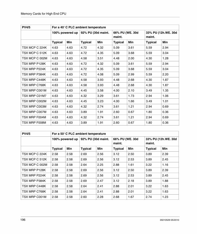
Memory Cards for High End CPU
PV4/5 For a 40° C PLC ambient temperature
100% powered up 92% PU (30d maint. 66% PU (WE. 30d maint.
33% PU (12h.WE. 30d maint.
Typical Min Typical Min Typical Min Typical Min
TSX MCP C 224K 4.63 4.63 4.72 4.32 5.09 3.61 5.59 2.94
TSX MCP C 512K 4.63 4.63 4.72 4.35 5.09 3.68 5.59 3.04
TSX MCP C 002M 4.63 4.63 4.58 3.51 4.48 2.00 4.30 1.28
TSX MRP P128K 4.63 4.63 4.72 4.32 5.09 3.61 5.59 2.94
TSX MRP P224K 4.63 4.63 4.72 4.35 5.09 3.68 5.59 3.04
TSX MRP P384K 4.63 4.63 4.72 4.08 5.09 2.99 5.59 2.20
TSX MRP C448K 4.63 4.63 4.58 3.93 4.48 2.68 4.30 1.87
TSX MRP C768K 4.63 4.63 4.58 3.93 4.48 2.68 4.30 1.87
TSX MRP C001M 4.63 4.63 4.45 3.58 4.00 2.10 3.49 1.35
TSX MRP C01M7 4.63 4.63 4.32 3.29 3.61 1.73 2.94 1.06
TSX MRP C002M 4.63 4.63 4.45 3.23 4.00 1.66 3.49 1.01
TSX MRP C003M 4.63 4.63 4.32 2.74 3.61 1.21 2.94 0.69
TSX MRP C007M 4.63 4.63 3.89 1.91 2.60 0.67 1.80 0.36
TSX MRP F004M 4.63 4.63 4.32 2.74 3.61 1.21 2.94 0.69
TSX MRP F008M 4.63 4.63 3.89 1.91 2.60 0.67 1.80 0.36
PV4/5 For a 50° C PLC ambient temperature
100% powered up 92% PU (30d maint. 66% PU (WE. 30d maint.
33% PU (12h.WE. 30d maint.
Typical Min Typical Min Typical Min Typical Min
TSX MCP C 224K 2.58 2.58 2.69 2.56 3.12 2.50 3.89 2.39
TSX MCP C 512K 2.58 2.58 2.69 2.56 3.12 2.53 3.89 2.45
TSX MCP C 002M 2.58 2.58 2.64 2.25 2.88 1.61 3.22 1.16
TSX MRP P128K 2.58 2.58 2.69 2.56 3.12 2.50 3.89 2.39
TSX MRP P224K 2.58 2.58 2.69 2.56 3.12 2.53 3.89 2.45
TSX MRP P384K 2.58 2.58 2.69 2.47 3.12 2.18 3.89 1.88
TSX MRP C448K 2.58 2.58 2.64 2.41 2.88 2.01 3.22 1.63
TSX MRP C768K 2.58 2.58 2.64 2.41 2.88 2.01 3.22 1.63
TSX MRP C001M 2.58 2.58 2.60 2.28 2.68 1.67 2.74 1.23
196 35010529 05/2010
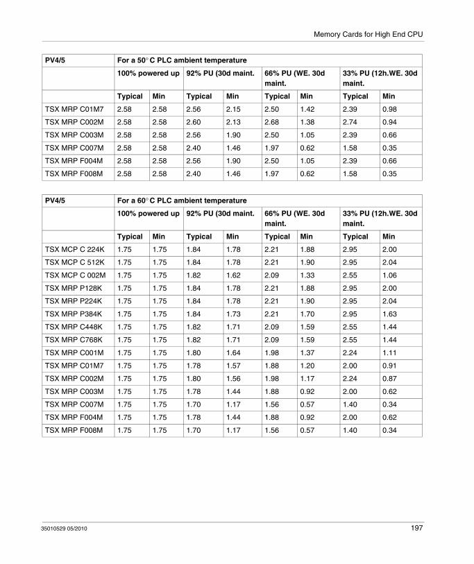
Memory Cards for High End CPU
TSX MRP C01M7 2.58 2.58 2.56 2.15 2.50 1.42 2.39 0.98
TSX MRP C002M 2.58 2.58 2.60 2.13 2.68 1.38 2.74 0.94
TSX MRP C003M 2.58 2.58 2.56 1.90 2.50 1.05 2.39 0.66
TSX MRP C007M 2.58 2.58 2.40 1.46 1.97 0.62 1.58 0.35
TSX MRP F004M 2.58 2.58 2.56 1.90 2.50 1.05 2.39 0.66
TSX MRP F008M 2.58 2.58 2.40 1.46 1.97 0.62 1.58 0.35
PV4/5 For a 50° C PLC ambient temperature
100% powered up 92% PU (30d maint. 66% PU (WE. 30d maint.
33% PU (12h.WE. 30d maint.
Typical Min Typical Min Typical Min Typical Min
PV4/5 For a 60° C PLC ambient temperature
100% powered up 92% PU (30d maint. 66% PU (WE. 30d maint.
33% PU (12h.WE. 30d maint.
Typical Min Typical Min Typical Min Typical Min
TSX MCP C 224K 1.75 1.75 1.84 1.78 2.21 1.88 2.95 2.00
TSX MCP C 512K 1.75 1.75 1.84 1.78 2.21 1.90 2.95 2.04
TSX MCP C 002M 1.75 1.75 1.82 1.62 2.09 1.33 2.55 1.06
TSX MRP P128K 1.75 1.75 1.84 1.78 2.21 1.88 2.95 2.00
TSX MRP P224K 1.75 1.75 1.84 1.78 2.21 1.90 2.95 2.04
TSX MRP P384K 1.75 1.75 1.84 1.73 2.21 1.70 2.95 1.63
TSX MRP C448K 1.75 1.75 1.82 1.71 2.09 1.59 2.55 1.44
TSX MRP C768K 1.75 1.75 1.82 1.71 2.09 1.59 2.55 1.44
TSX MRP C001M 1.75 1.75 1.80 1.64 1.98 1.37 2.24 1.11
TSX MRP C01M7 1.75 1.75 1.78 1.57 1.88 1.20 2.00 0.91
TSX MRP C002M 1.75 1.75 1.80 1.56 1.98 1.17 2.24 0.87
TSX MRP C003M 1.75 1.75 1.78 1.44 1.88 0.92 2.00 0.62
TSX MRP C007M 1.75 1.75 1.70 1.17 1.56 0.57 1.40 0.34
TSX MRP F004M 1.75 1.75 1.78 1.44 1.88 0.92 2.00 0.62
TSX MRP F008M 1.75 1.75 1.70 1.17 1.56 0.57 1.40 0.34
35010529 05/2010 197

Memory Cards for High End CPU
Main Battery Lifetime of PV6 PCMCIA (in Years)
The table below presents the lifetime of main battery TSX BAT M02 (PV6) for PCMCIA memory cards:
PV6 For a 25° C PLC ambient temperature
100% powered up 92% PU (30d maint. 66% PU (WE. 30d maint.
33% PU (12h.WE. 30d maint.
Typical Min Typical Min Typical Min Typical Min
TSX MCP C 224K 7.2 7.2 7.2 6.3 7.0 4.5 6.8 3.2
TSX MCP C 512K 7.2 7.2 7.2 6.5 7.0 5.1 6.8 3.9
TSX MCP C 002M 7.2 7.2 6.8 5.8 5.9 3.6 5.0 2.4
TSX MRP P128K 7.2 7.2 7.2 6.3 7.0 4.5 6.8 3.2
TSX MRP P224K 7.2 7.2 7.2 6.5 7.0 5.1 6.8 3.9
TSX MRP P384K 7.2 7.2 7.2 6.5 7.0 5.1 6.8 3.9
TSX MRP C448K 7.2 7.2 6.8 5.8 5.9 3.6 5.0 2.4
TSX MRP C768K 7.2 7.2 6.8 5.8 5.9 3.6 5.0 2.4
TSX MRP C001M 7.2 7.2 6.5 5.2 5.1 2.8 3.9 1.7
TSX MRP C01M7 7.2 7.2 6.3 4.7 4.5 2.3 3.2 1.4
TSX MRP C002M 7.2 7.2 6.5 5.2 5.1 2.8 3.9 1.7
TSX MRP C003M 7.2 7.2 6.3 4.7 4.5 2.3 3.2 1.4
TSX MRP C007M 7.2 7.2 5.4 3.5 3.0 1.3 1.9 0.7
TSX MRP F004M 7.2 7.2 6.3 4.7 4.5 2.3 3.2 1.4
TSX MRP F008M 7.2 7.2 5.4 3.5 3.0 1.3 1.9 0.7
PV6 For a 40° C PLC ambient temperature
100% powered up 92% PU (30d maint. 66% PU (WE. 30d maint.
33% PU (12h.WE. 30d maint.
Typical Min Typical Min Typical Min Typical Min
TSX MCP C 224K 4.6 4.6 4.7 4.3 5.1 3.6 5.6 2.9
TSX MCP C 512K 4.6 4.6 4.7 4.4 5.1 4.0 5.6 3.5
TSX MCP C 002M 4.6 4.6 4.6 4.1 4.5 3.0 4.3 2.2
TSX MRP P128K 4.6 4.6 4.7 4.3 5.1 3.6 5.6 2.9
TSX MRP P224K 4.6 4.6 4.7 4.4 5.1 4.0 5.6 3.5
TSX MRP P384K 4.6 4.6 4.7 4.4 5.1 4.0 5.6 3.5
TSX MRP C448K 4.6 4.6 4.6 4.1 4.5 3.0 4.3 2.2
TSX MRP C768K 4.6 4.6 4.6 4.1 4.5 3.0 4.3 2.2
TSX MRP C001M 4.6 4.6 4.4 3.8 4.0 2.4 3.5 1.6
198 35010529 05/2010
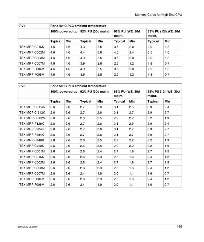
Memory Cards for High End CPU
TSX MRP C01M7 4.6 4.6 4.3 3.5 3.6 2.0 2.9 1.3
TSX MRP C002M 4.6 4.6 4.4 3.8 4.0 2.4 3.5 1.6
TSX MRP C003M 4.6 4.6 4.3 3.5 3.6 2.0 2.9 1.3
TSX MRP C007M 4.6 4.6 3.9 2.8 2.6 1.2 1.8 0.7
TSX MRP F004M 4.6 4.6 4.3 3.5 3.6 2.0 2.9 1.3
TSX MRP F008M 4.6 4.6 3.9 2.8 2.6 1.2 1.8 0.7
PV6 For a 40° C PLC ambient temperature
100% powered up 92% PU (30d maint. 66% PU (WE. 30d maint.
33% PU (12h.WE. 30d maint.
Typical Min Typical Min Typical Min Typical Min
PV6 For a 50° C PLC ambient temperature
100% powered up 92% PU (30d maint. 66% PU (WE. 30d maint.
33% PU (12h.WE. 30d maint.
Typical Min Typical Min Typical Min Typical Min
TSX MCP C 224K 2.6 2.6 2.7 2.6 3.1 2.5 3.9 2.4
TSX MCP C 512K 2.6 2.6 2.7 2.6 3.1 2.7 3.9 2.7
TSX MCP C 002M 2.6 2.6 2.6 2.5 2.9 2.2 3.2 1.9
TSX MRP P128K 2.6 2.6 2.7 2.6 3.1 2.5 3.9 2.4
TSX MRP P224K 2.6 2.6 2.7 2.6 3.1 2.7 3.9 2.7
TSX MRP P384K 2.6 2.6 2.7 2.6 3.1 2.7 3.9 2.7
TSX MRP C448K 2.6 2.6 2.6 2.5 2.9 2.2 3.2 1.9
TSX MRP C768K 2.6 2.6 2.6 2.5 2.9 2.2 3.2 1.9
TSX MRP C001M 2.6 2.6 2.6 2.4 2.7 1.9 2.7 1.5
TSX MRP C01M7 2.6 2.6 2.6 2.3 2.5 1.6 2.4 1.2
TSX MRP C002M 2.6 2.6 2.6 2.4 2.7 1.9 2.7 1.5
TSX MRP C003M 2.6 2.6 2.6 2.3 2.5 1.6 2.4 1.2
TSX MRP C007M 2.6 2.6 2.4 1.9 2.0 1.1 1.6 0.7
TSX MRP F004M 2.6 2.6 2.6 2.3 2.5 1.6 2.4 1.2
TSX MRP F008M 2.6 2.6 2.4 1.9 2.0 1.1 1.6 0.7
35010529 05/2010 199

Memory Cards for High End CPU
Minimum Lifetime of the Main Battery, in a Powered Down PLC
In a powered down PLC, the minimum lifetime of the main battery is 6 months in PV6 PCMCIAs.
Auxiliary Battery Lifetime
The auxiliary battery TSX BATM 03 is included in the PCMCIA product. Whatever the usage cases and ambient temperature, the lifetime of the auxiliary battery is:
5 years in PV1/2/31.7 years in PV4/55 years in PV6
PV6 For a 60° C PLC ambient temperature
100% powered up 92% PU (30d maint. 66% PU (WE. 30d maint.
33% PU (12h.WE. 30d maint.
Typical Min Typical Min Typical Min Typical Min
TSX MCP C 224K 1.8 1.8 1.8 1.8 2.2 1.9 3.0 2.0
TSX MCP C 512K 1.8 1.8 1.8 1.8 2.2 2.0 3.0 2.2
TSX MCP C 002M 1.8 1.8 1.8 1.7 2.1 1.7 2.5 1.6
TSX MRP P128K 1.8 1.8 1.8 1.8 2.2 1.9 3.0 2.0
TSX MRP P224K 1.8 1.8 1.8 1.8 2.2 2.0 3.0 2.2
TSX MRP P384K 1.8 1.8 1.8 1.8 2.2 2.0 3.0 2.2
TSX MRP C448K 1.8 1.8 1.8 1.7 2.1 1.7 2.5 1.6
TSX MRP C768K 1.8 1.8 1.8 1.7 2.1 1.7 2.5 1.6
TSX MRP C001M 1.8 1.8 1.8 1.7 2.0 1.5 2.2 1.3
TSX MRP C01M7 1.8 1.8 1.8 1.6 1.9 1.3 2.0 1.1
TSX MRP C002M 1.8 1.8 1.8 1.7 2.0 1.5 2.2 1.3
TSX MRP C003M 1.8 1.8 1.8 1.6 1.9 1.3 2.0 1.1
TSX MRP C007M 1.8 1.8 1.7 1.4 1.6 0.9 1.4 0.6
TSX MRP F004M 1.8 1.8 1.8 1.6 1.9 1.3 2.0 1.1
TSX MRP F008M 1.8 1.8 1.7 1.4 1.6 0.9 1.4 0.6
200 35010529 05/2010

35010529 05/2010
III
Power Supply
35010529 05/2010
Power Supply Modules (CPS)
Introduction
This part provides information on the Quantum Power Supply modules.
What's in this Part?
This part contains the following chapters:
Chapter Chapter Name Page
11 General Information 203
12 140 CPS 111 00: 115 ... 230 VAC Standalone 3 A Power Supply Module
217
13 140 CPS 111 00 (PV 01 or greater): 115 ... 230 VAC Standalone Power Supply Module
221
14 140 CPS 114 00: 115/230 VAC Standalone 8 A Power Supply Module
225
15 140 CPS 114 10: 115/230 VAC Standalone/Summable 8 A Power Supply Module
229
16 140 CPS 114 20: 115/230 VAC Standalone/Summable 11 A Power Supply Module
233
17 140 CPS 124 00: 115/230 VAC Standalone/Redundant 8 A Power Supply Module
237
18 140 CPS 124 20: 115/230 VAC Standalone/Redundant 11 A Power Supply Module
241
19 140 CPS 211 00: 24 VDC Standalone 3 A Power Supply Module
245
20 140 CPS 214 00: 24 VDC Standalone/Summable 7–8 A Power Supply Module
249
201
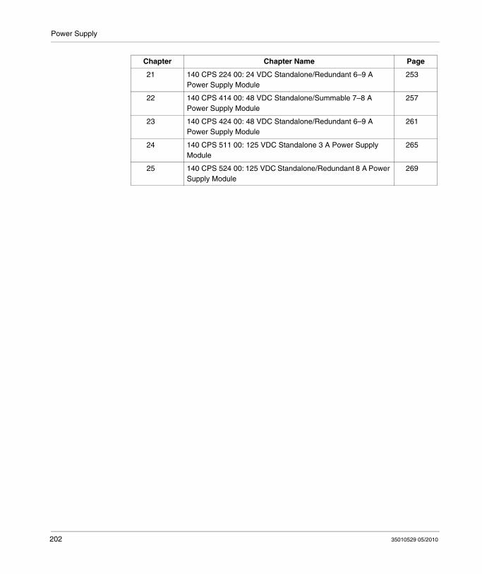
Power Supply
21 140 CPS 224 00: 24 VDC Standalone/Redundant 6–9 A Power Supply Module
253
22 140 CPS 414 00: 48 VDC Standalone/Summable 7–8 A Power Supply Module
257
23 140 CPS 424 00: 48 VDC Standalone/Redundant 6–9 A Power Supply Module
261
24 140 CPS 511 00: 125 VDC Standalone 3 A Power Supply Module
265
25 140 CPS 524 00: 125 VDC Standalone/Redundant 8 A Power Supply Module
269
Chapter Chapter Name Page
202 35010529 05/2010

35010529 05/2010
11
General Information
35010529 05/2010
General Information
Purpose
This chapter provides general information of the Quantum Power Supplies.
What's in this Chapter?
This chapter contains the following topics:
Topic Page
Table of Power Supplies 204
System Design Considerations for Quantum Power Supplies 205
Compatibility 210
Presentation 212
Indicators 213
Displaying the Power Supply Budget 214
203

General Information
Table of Power Supplies
Overview
Type Part Numbers Source Voltage Bus Current
Standalone 140 CPS 111 00 115 ... 230 VAC 3 A
140 CPS 114 00 115/230 VAC 8 A
140 CPS 211 00 24 VDC 3 A
140 CPS 511 00 125 VDC 3 A
Standalone/Summable 140 CPS 114 10 115/230 VAC 8 A
140 CPS 114 20 115/230 VAC 11 A
140 CPS 214 00 24 VDC 7–8 A
140 CPS 414 00 48 ... 72 VDC 7–8 A
Standalone/Redundant 140 CPS 124 00 115/230 VAC 8 A
140 CPS 124 20 115/230 VAC 11 A
140 CPS 224 00 24 VDC 6–9 A
140 CPS 424 00 48 ... 72 VDC 6–9 A
140 CPS 524 00 125 VDC 8 A
WARNINGUNINTENDED EQUIPMENT OPERATION
Use identical power supplies with the exceptions noted in this chapter.
Failure to follow these instructions can result in death, serious injury, or equipment damage.
204 35010529 05/2010
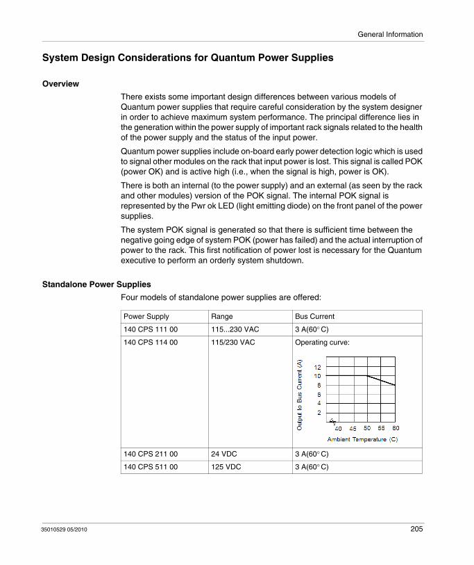
General Information
System Design Considerations for Quantum Power Supplies
Overview
There exists some important design differences between various models of Quantum power supplies that require careful consideration by the system designer in order to achieve maximum system performance. The principal difference lies in the generation within the power supply of important rack signals related to the health of the power supply and the status of the input power.
Quantum power supplies include on-board early power detection logic which is used to signal other modules on the rack that input power is lost. This signal is called POK (power OK) and is active high (i.e., when the signal is high, power is OK).
There is both an internal (to the power supply) and an external (as seen by the rack and other modules) version of the POK signal. The internal POK signal is represented by the Pwr ok LED (light emitting diode) on the front panel of the power supplies.
The system POK signal is generated so that there is sufficient time between the negative going edge of system POK (power has failed) and the actual interruption of power to the rack. This first notification of power lost is necessary for the Quantum executive to perform an orderly system shutdown.
Standalone Power Supplies
Four models of standalone power supplies are offered:
Power Supply Range Bus Current
140 CPS 111 00 115...230 VAC 3 A(60° C)
140 CPS 114 00 115/230 VAC Operating curve:
140 CPS 211 00 24 VDC 3 A(60° C)
140 CPS 511 00 125 VDC 3 A(60° C)
35010529 05/2010 205

General Information
The following figure shows the direction of the internal POK to the Quantum system POK.
Summable Power Supplies
Four summable power supply models are offered:
CAUTIONUNINTENDED EQUIPMENT OPERATION
When a rack is equipped with a standalone power supply do not install any other power supply.
When the power supply must be redundant, install redundant power supply units.
Failure to follow these instructions can result in injury or equipment damage.
Power Supply Range Bus Current
140 CPS 114 10 115/230 VAC 8 A (60° C)
140 CPS 114 20 115/230 VAC 11 A (60° C)
140 CPS 214 00 24 VDC Operating curve:
206 35010529 05/2010

General Information
A summable power supply may be used as a standalone power supply without reservation in any Quantum system.
For systems configured with a mix of CPS, NOM, expert, and l/O modules, whose total current consumption from the rack exceeds the current provided by one summable supply, two summable supplies may be used in a single rack. In such a system, the total current available on the rack is the sum of the capability of both supplies (i.e., 2 x 8 A = 16 A). The summable supplies are designed so that they split the current supplied to the load almost equally, which also has the added benefit of increasing total system MTBF, and to distribute the thermal load across the rack. Summable supplies should be installed in the end module positions in the Quantum rack to maximize the system thermal performance.
The Quantum system POK signal in systems powered by two summable power supplies is only true (power is OK) when both internal POK signals (in the 140 CPS •14 •0) are true. Quantum summable power supplies are not hot-swappable.
The following figure shows the direction of the Quantum POK summable power supplies.
The proper method for starting systems powered by summable power supplies is to insert both supplies in the rack in an unpowered state, and then apply power to each supply. There is no requirement to turn on each supply simultaneously. The system designer must realize that the operation of the summable supply described above is independent of total rack load, i.e., even if the total load on the rack is less than 8 A, if there are two summable supplies installed in the rack, the system POK is generated as shown in this section.
For the special case of a single summable supply used as a standalone, the system POK generation reverts to the standalone case as shown previously in this section.
140 CPS 414 00 48 ... 72 VDC Operating curve:
35010529 05/2010 207
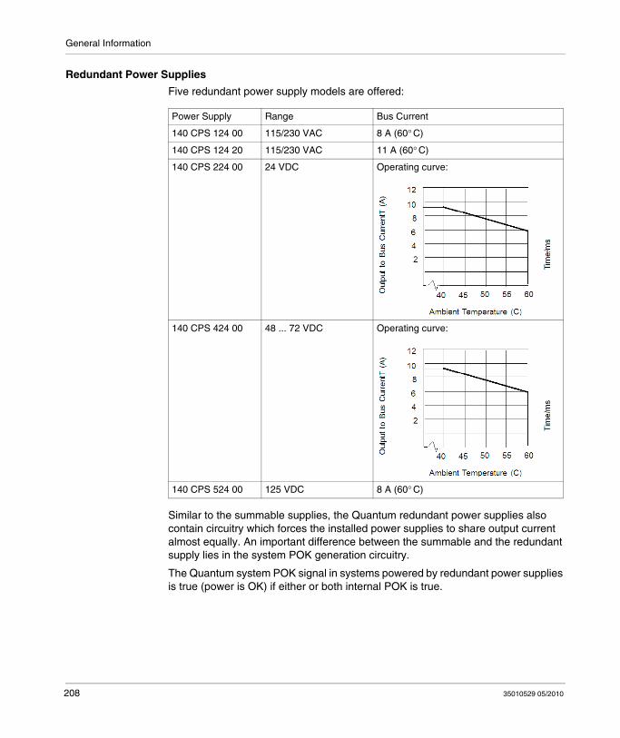
General Information
Redundant Power Supplies
Five redundant power supply models are offered:
Similar to the summable supplies, the Quantum redundant power supplies also contain circuitry which forces the installed power supplies to share output current almost equally. An important difference between the summable and the redundant supply lies in the system POK generation circuitry.
The Quantum system POK signal in systems powered by redundant power supplies is true (power is OK) if either or both internal POK is true.
Power Supply Range Bus Current
140 CPS 124 00 115/230 VAC 8 A (60° C)
140 CPS 124 20 115/230 VAC 11 A (60° C)
140 CPS 224 00 24 VDC Operating curve:
140 CPS 424 00 48 ... 72 VDC Operating curve:
140 CPS 524 00 125 VDC 8 A (60° C)
208 35010529 05/2010
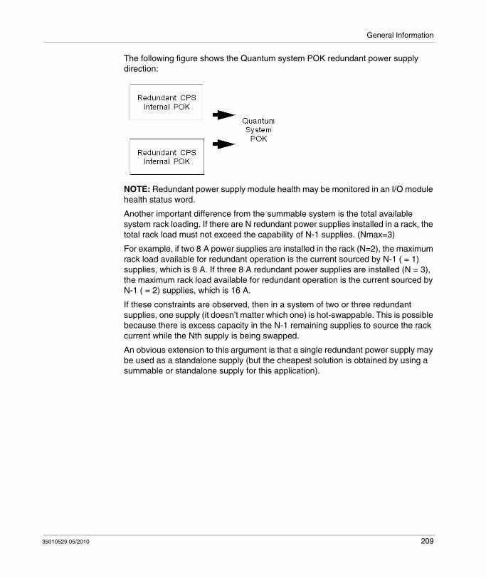
General Information
The following figure shows the Quantum system POK redundant power supply direction:
NOTE: Redundant power supply module health may be monitored in an I/O module health status word.
Another important difference from the summable system is the total available system rack loading. If there are N redundant power supplies installed in a rack, the total rack load must not exceed the capability of N-1 supplies. (Nmax=3)
For example, if two 8 A power supplies are installed in the rack (N=2), the maximum rack load available for redundant operation is the current sourced by N-1 ( = 1) supplies, which is 8 A. If three 8 A redundant power supplies are installed (N = 3), the maximum rack load available for redundant operation is the current sourced by N-1 ( = 2) supplies, which is 16 A.
If these constraints are observed, then in a system of two or three redundant supplies, one supply (it doesn’t matter which one) is hot-swappable. This is possible because there is excess capacity in the N-1 remaining supplies to source the rack current while the Nth supply is being swapped.
An obvious extension to this argument is that a single redundant power supply may be used as a standalone supply (but the cheapest solution is obtained by using a summable or standalone supply for this application).
35010529 05/2010 209
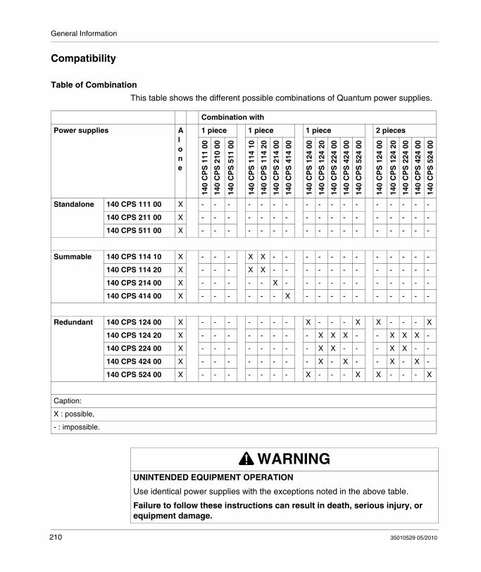
General Information
Compatibility
Table of Combination
This table shows the different possible combinations of Quantum power supplies.
Combination with
Power supplies Alone
1 piece 1 piece 1 piece 2 pieces
140
CP
S 1
11 0
0
140
CP
S 2
10 0
0
140
CP
S 5
11 0
0
140
CP
S 1
14 1
0
140
CP
S 1
14 2
0
140
CP
S 2
14 0
0
140
CP
S 4
14 0
0
140
CP
S 1
24 0
0
140
CP
S 1
24 2
0
140
CP
S 2
24 0
0
140
CP
S 4
24 0
0
140
CP
S 5
24 0
0
140
CP
S 1
24 0
0
140
CP
S 1
24 2
0
140
CP
S 2
24 0
0
140
CP
S 4
24 0
0
140
CP
S 5
24 0
0
Standalone 140 CPS 111 00 X - - - - - - - - - - - - - - - - -
140 CPS 211 00 X - - - - - - - - - - - - - - - - -
140 CPS 511 00 X - - - - - - - - - - - - - - - - -
Summable 140 CPS 114 10 X - - - X X - - - - - - - - - - - -
140 CPS 114 20 X - - - X X - - - - - - - - - - - -
140 CPS 214 00 X - - - - - X - - - - - - - - - - -
140 CPS 414 00 X - - - - - - X - - - - - - - - - -
Redundant 140 CPS 124 00 X - - - - - - - X - - - X X - - - X
140 CPS 124 20 X - - - - - - - - X X X - - X X X -
140 CPS 224 00 X - - - - - - - - X X - - - X X - -
140 CPS 424 00 X - - - - - - - - X - X - - X - X -
140 CPS 524 00 X - - - - - - - X - - - X X - - - X
Caption:
X : possible,
- : impossible.
WARNINGUNINTENDED EQUIPMENT OPERATION
Use identical power supplies with the exceptions noted in the above table.
Failure to follow these instructions can result in death, serious injury, or equipment damage.
210 35010529 05/2010

General Information
Compatibility Issues
Power supplies:Do not use a standalone power supply in combination with any other supply in the same backplane. With the exception of standalone models, power supplies with the same model number are compatible when installed in the same backplane.
DIO:While it is possible to use a standalone or a summable power supply with a DIO drop (as long as the DIO input is left unpowered), it is not possible to use a redundant supply with the DIO drop. The added power supply need not be of the same type as the DIO adapter. AC powered supplies may be used with DC type adapters and vice-versa. DIO module current load with an added power supply is typically 200 mA.
35010529 05/2010 211

General Information
Presentation
Illustration
The following figure shows the power supply module.
1 LED Area2 Model Number, Module Description, Color Code3 Field Wiring Connector4 Field Wiring Connector Cover 5 Removable door6 Customer Identification Label, (Fold label and place it inside door)
NOTE: When field wiring the power supply module, the maximum wire size that should be used is 1 - 14 AWG or 2 - 16 AWG; the minimum is 20 AWG.
212 35010529 05/2010
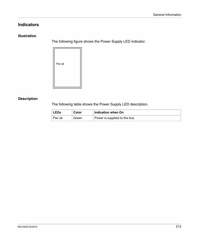
General Information
Indicators
Illustration
The following figure shows the Power Supply LED indicator.
Description
The following table shows the Power Supply LED description.
LEDs Color Indication when On
Pwr ok Green Power is supplied to the bus.
35010529 05/2010 213
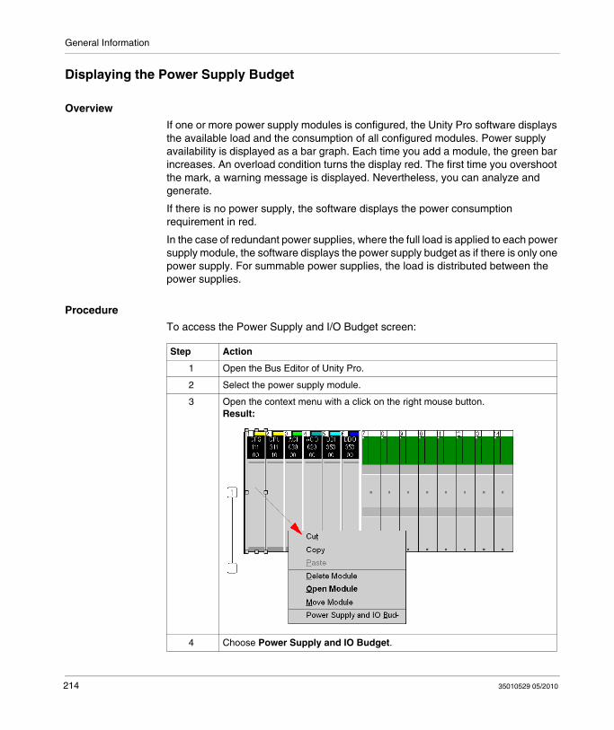
General Information
Displaying the Power Supply Budget
Overview
If one or more power supply modules is configured, the Unity Pro software displays the available load and the consumption of all configured modules. Power supply availability is displayed as a bar graph. Each time you add a module, the green bar increases. An overload condition turns the display red. The first time you overshoot the mark, a warning message is displayed. Nevertheless, you can analyze and generate.
If there is no power supply, the software displays the power consumption requirement in red.
In the case of redundant power supplies, where the full load is applied to each power supply module, the software displays the power supply budget as if there is only one power supply. For summable power supplies, the load is distributed between the power supplies.
Procedure
To access the Power Supply and I/O Budget screen:
Step Action
1 Open the Bus Editor of Unity Pro.
2 Select the power supply module.
3 Open the context menu with a click on the right mouse button.Result:
4 Choose Power Supply and IO Budget.
214 35010529 05/2010

General Information
Presentation
Here is a sample screen:
35010529 05/2010 215

General Information
216 35010529 05/2010
35010529 05/2010
12
140 CPS 111 00
35010529 05/2010
140 CPS 111 00: 115 ... 230 VAC Standalone 3 A Power Supply Module
Purpose
This chapter provides information on the 140 CPS 111 00 Power Supply module.
What's in this Chapter?
This chapter contains the following topics:
Topic Page
140 CPS 111 00 Wiring Diagram 218
140 CPS 111 00 Specifications 219
217

140 CPS 111 00
140 CPS 111 00 Wiring Diagram
Wiring Diagram
NOTE: For closed system installations, you must use connector 140 XTS 005 00.
DANGERELECTRIC SHOCK
Ensure that the installation complies with wiring, grounding and electromagnetic standards defined in:
national and local electrical code requirements,Grounding and Electromagnetic Compatibility of PLC Systems (see Grounding and Electromagnetic Compatibility of PLC Systems, Basic Principles and Measures, User Manual) user manual.
Failure to follow these instructions will result in death or serious injury.
218 35010529 05/2010

140 CPS 111 00
140 CPS 111 00 Specifications
General Specifications
Input
Output to Bus
Operating mode Standalone
Internal power dissipation (electric losses)
6.5 W
Network power consumption Electric losses + (5.1 x Iout)1
Power factor 0.5
1: Iout: sum of currents consumption by all modules in rack (in A)
Input voltage 100 ... 276 VAC
Input frequency 47 ... 63 Hz
Input voltage total harmonic distortion
Less than 10% of the fundamental rms value
Input current 0.4 A @ 115 V AC0.2 A @ 230 V AC
Inrush current 10 A @ 115 V AC20 A @ 230 V AC
VA rating 50 VA
Fusing (external) 1.5 A slow-blow fuse
Input power interruption 1/2 cycle @ full load and minimum rated line voltage / frequency. No less than 1 s between interruptions.
Voltage 5.1 VDC
Current 3 A max.
0.3 A min.
Protection Overcurrent, overvoltage
35010529 05/2010 219

140 CPS 111 00
220 35010529 05/2010

35010529 05/2010
13
35010529 05/2010
140 CPS 111 00 (PV 01 or greater): 115 ... 230 VAC Standalone Power Supply Module
Purpose
This chapter provides information on the 140 CPS 111 00 (PV 01 or greater) Power Supply module.
What's in this Chapter?
This chapter contains the following topics:
Topic Page
140 CPS 111 00 (PV 01 or greater) Wiring Diagram 222
140 CPS 111 00 (PV 01 or greater) Specifications 223
221
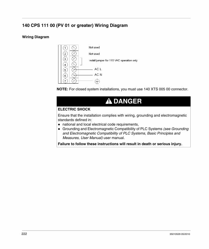
140 CPS 111 00 (PV 01 or greater) Wiring Diagram
Wiring Diagram
NOTE: For closed system installations, you must use 140 XTS 005 00 connector.
DANGERELECTRIC SHOCK
Ensure that the installation complies with wiring, grounding and electromagnetic standards defined in:
national and local electrical code requirements,Grounding and Electromagnetic Compatibility of PLC Systems (see Grounding and Electromagnetic Compatibility of PLC Systems, Basic Principles and Measures, User Manual) user manual.
Failure to follow these instructions will result in death or serious injury.
222 35010529 05/2010

140 CPS 111 00 (PV 01 or greater) Specifications
General Specifications
Input
Output to Bus
Operating mode Standalone
Internal power dissipation (electric losses)
6.5 W
Network power consumption Electric losses + (5.1 x Iout)1
Power factor 0.5
1: Iout: sum of currents consumption by all modules in rack (in A)
Input voltage 100 ... 276 VAC
Input frequency 47 ... 63 Hz
Input voltage total harmonic distortion
Less than 10% of the fundamental ms value
Input current 0.4 A @ 115 VAC; 0.2 A @ 230 VAC
Inrush current 10 A @ 115 VAC; 20 A @ 230 VAC
VA rating 50 VA
Fusing (external) 1.5 A slow-blow fuse
Input power interruption 1/2 cycle @ full load and minimum rated line voltage / frequency. No less than 1 s between interruptions.
Voltage 5.1 V dc
Current 3 A max.
0.3 A min.
Protection Overcurrent, overvoltage
35010529 05/2010 223

224 35010529 05/2010
35010529 05/2010
14
140 CPS 114 00
35010529 05/2010
140 CPS 114 00: 115/230 VAC Standalone 8 A Power Supply Module
Purpose
This chapter provides information on the 140 CPS 114 00 Power Supply module.
What's in this Chapter?
This chapter contains the following topics:
Topic Page
140 CPS 114 00 Wiring Diagram 226
140 CPS 114 00 Specifications 227
225

140 CPS 114 00
140 CPS 114 00 Wiring Diagram
Wiring Diagram
DANGERELECTRIC SHOCK
Ensure that the installation complies with wiring, grounding and electromagnetic standards defined in:
national and local electrical code requirements,Grounding and Electromagnetic Compatibility of PLC Systems (see Grounding and Electromagnetic Compatibility of PLC Systems, Basic Principles and Measures, User Manual) user manual.
Failure to follow these instructions will result in death or serious injury.
226 35010529 05/2010
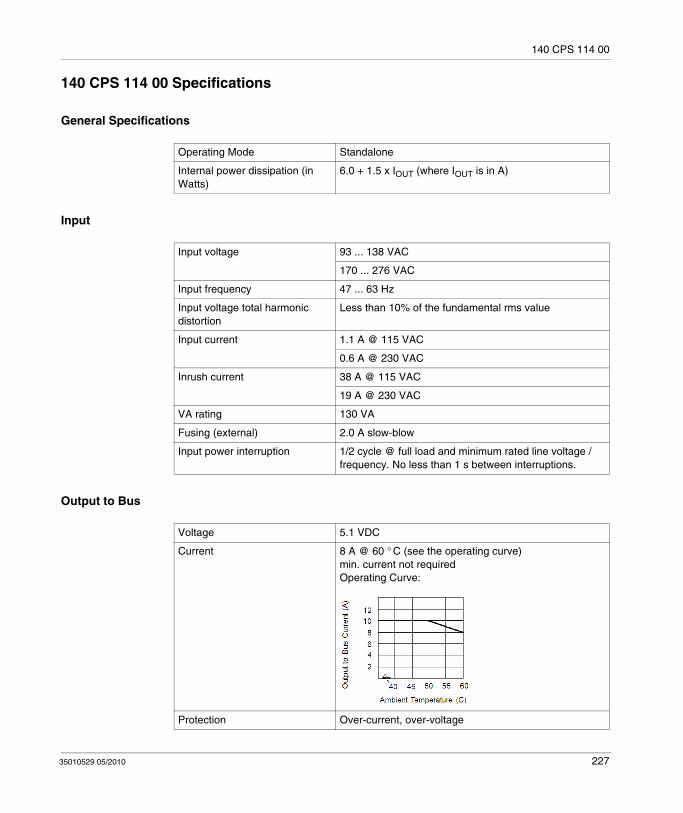
140 CPS 114 00
140 CPS 114 00 Specifications
General Specifications
Input
Output to Bus
Operating Mode Standalone
Internal power dissipation (in Watts)
6.0 + 1.5 x IOUT (where IOUT is in A)
Input voltage 93 ... 138 VAC
170 ... 276 VAC
Input frequency 47 ... 63 Hz
Input voltage total harmonic distortion
Less than 10% of the fundamental rms value
Input current 1.1 A @ 115 VAC
0.6 A @ 230 VAC
Inrush current 38 A @ 115 VAC
19 A @ 230 VAC
VA rating 130 VA
Fusing (external) 2.0 A slow-blow
Input power interruption 1/2 cycle @ full load and minimum rated line voltage / frequency. No less than 1 s between interruptions.
Voltage 5.1 VDC
Current 8 A @ 60 ° C (see the operating curve)min. current not requiredOperating Curve:
Protection Over-current, over-voltage
35010529 05/2010 227

140 CPS 114 00
228 35010529 05/2010

35010529 05/2010
15
140 CPS 114 10
35010529 05/2010
140 CPS 114 10: 115/230 VAC Standalone/Summable 8 A Power Supply Module
Purpose
This chapter provides information on the 140 CPS 114 10 Power Supply module.
What's in this Chapter?
This chapter contains the following topics:
Topic Page
140 CPS 114 10 Wiring Diagram 230
140 CPS 114 10 Specifications 231
229

140 CPS 114 10
140 CPS 114 10 Wiring Diagram
Wiring Diagram
DANGERELECTRIC SHOCK
Ensure that the installation complies with wiring, grounding and electromagnetic standards defined in:
national and local electrical code requirements,Grounding and Electromagnetic Compatibility of PLC Systems (see Grounding and Electromagnetic Compatibility of PLC Systems, Basic Principles and Measures, User Manual) user manual.
Failure to follow these instructions will result in death or serious injury.
230 35010529 05/2010
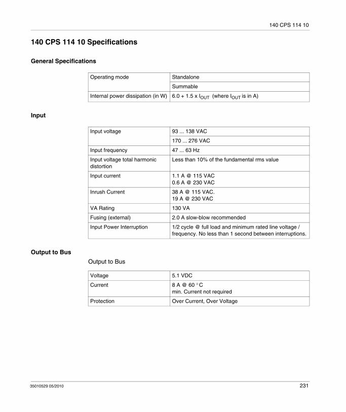
140 CPS 114 10
140 CPS 114 10 Specifications
General Specifications
Input
Output to Bus
Output to Bus
Operating mode Standalone
Summable
Internal power dissipation (in W) 6.0 + 1.5 x IOUT (where IOUT is in A)
Input voltage 93 ... 138 VAC
170 ... 276 VAC
Input frequency 47 ... 63 Hz
Input voltage total harmonic distortion
Less than 10% of the fundamental rms value
Input current 1.1 A @ 115 VAC0.6 A @ 230 VAC
Inrush Current 38 A @ 115 VAC. 19 A @ 230 VAC
VA Rating 130 VA
Fusing (external) 2.0 A slow-blow recommended
Input Power Interruption 1/2 cycle @ full load and minimum rated line voltage / frequency. No less than 1 second between interruptions.
Voltage 5.1 VDC
Current 8 A @ 60 ° Cmin. Current not required
Protection Over Current, Over Voltage
35010529 05/2010 231

140 CPS 114 10
232 35010529 05/2010
35010529 05/2010
16
140 CPS 114 20
35010529 05/2010
140 CPS 114 20: 115/230 VAC Standalone/Summable 11 A Power Supply Module
Purpose
This chapter provides information on the 140 CPS 114 20 Power Supply module.
What's in this Chapter?
This chapter contains the following topics:
Topic Page
140 CPS 114 20 Wiring Diagram 234
140 CPS 114 20 Specifications 235
233
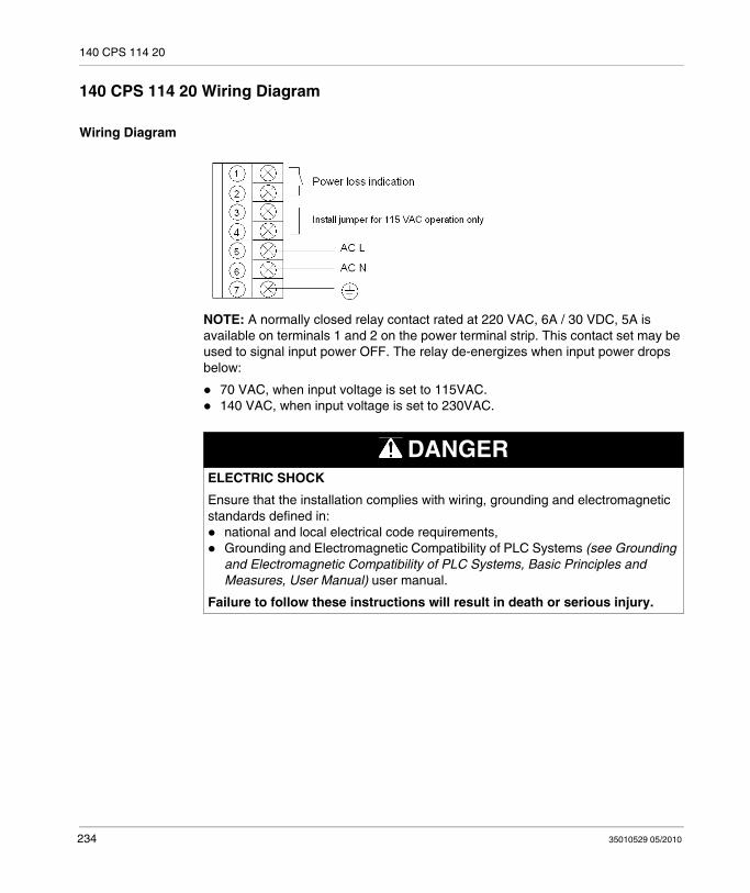
140 CPS 114 20
140 CPS 114 20 Wiring Diagram
Wiring Diagram
NOTE: A normally closed relay contact rated at 220 VAC, 6A / 30 VDC, 5A is available on terminals 1 and 2 on the power terminal strip. This contact set may be used to signal input power OFF. The relay de-energizes when input power drops below:
70 VAC, when input voltage is set to 115VAC.140 VAC, when input voltage is set to 230VAC.
DANGERELECTRIC SHOCK
Ensure that the installation complies with wiring, grounding and electromagnetic standards defined in:
national and local electrical code requirements,Grounding and Electromagnetic Compatibility of PLC Systems (see Grounding and Electromagnetic Compatibility of PLC Systems, Basic Principles and Measures, User Manual) user manual.
Failure to follow these instructions will result in death or serious injury.
234 35010529 05/2010

140 CPS 114 20
140 CPS 114 20 Specifications
General Specifications
140 CPS 114 20 power supplies are designed to not require the external EMI filter, ferrite bead and Olflex cable.
Input
Operating mode Standalone
Summable
Internal power dissipation (electric losses)
11 W
Network power consumption Electric losses + (5.1 x Iout)1
Power factor 0.5
1: Iout: sum of currents consumption by all modules in rack (in A)
Input voltage 93 ... 138 VAC
170 ... 264 VAC
Input frequency 47 ... 63 Hz
Input voltage total harmonic distortion
Less than 10% of the fundamental rms value
Input current 1.2 A @ 115 VAC
0.7 A @ 230 VAC
Inrush current ≤ 20 A @ 115 VAC
≤ 25 A @ 230 VAC
VA rating 160 VA @ 11 A
Fusing (external) 2.0 A slow-blow
Input power interruption 1/2 cycle @ full load and minimum rated line voltage / frequency. No less than 1 s between interruptions.
35010529 05/2010 235
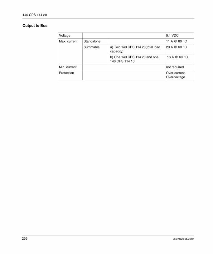
140 CPS 114 20
Output to Bus
Voltage 5.1 VDC
Max. current Standalone 11 A @ 60 ° C
Summable a) Two 140 CPS 114 20(total load capacity)
20 A @ 60 ° C
b) One 140 CPS 114 20 and one 140 CPS 114 10
16 A @ 60 ° C
Min. current not required
Protection Over-current, Over-voltage
236 35010529 05/2010

35010529 05/2010
17
140 CPS 124 00
35010529 05/2010
140 CPS 124 00: 115/230 VAC Standalone/Redundant 8 A Power Supply Module
Purpose
This chapter provides information on the 140 CPS 124 00 Power Supply module.
What's in this Chapter?
This chapter contains the following topics:
Topic Page
140 CPS 124 00 Wiring Diagram 238
140 CPS 124 00 Specifications 239
237

140 CPS 124 00
140 CPS 124 00 Wiring Diagram
Wiring Diagram
DANGERELECTRIC SHOCK
Ensure that the installation complies with wiring, grounding and electromagnetic standards defined in:
national and local electrical code requirements,Grounding and Electromagnetic Compatibility of PLC Systems (see Grounding and Electromagnetic Compatibility of PLC Systems, Basic Principles and Measures, User Manual) user manual.
Failure to follow these instructions will result in death or serious injury.
238 35010529 05/2010
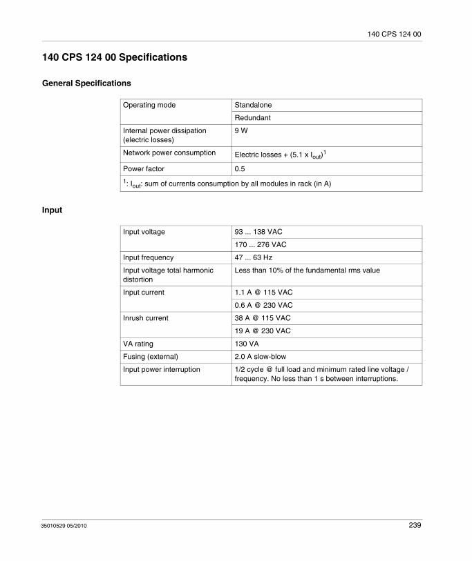
140 CPS 124 00
140 CPS 124 00 Specifications
General Specifications
Input
Operating mode Standalone
Redundant
Internal power dissipation (electric losses)
9 W
Network power consumption Electric losses + (5.1 x Iout)1
Power factor 0.5
1: Iout: sum of currents consumption by all modules in rack (in A)
Input voltage 93 ... 138 VAC
170 ... 276 VAC
Input frequency 47 ... 63 Hz
Input voltage total harmonic distortion
Less than 10% of the fundamental rms value
Input current 1.1 A @ 115 VAC
0.6 A @ 230 VAC
Inrush current 38 A @ 115 VAC
19 A @ 230 VAC
VA rating 130 VA
Fusing (external) 2.0 A slow-blow
Input power interruption 1/2 cycle @ full load and minimum rated line voltage / frequency. No less than 1 s between interruptions.
35010529 05/2010 239
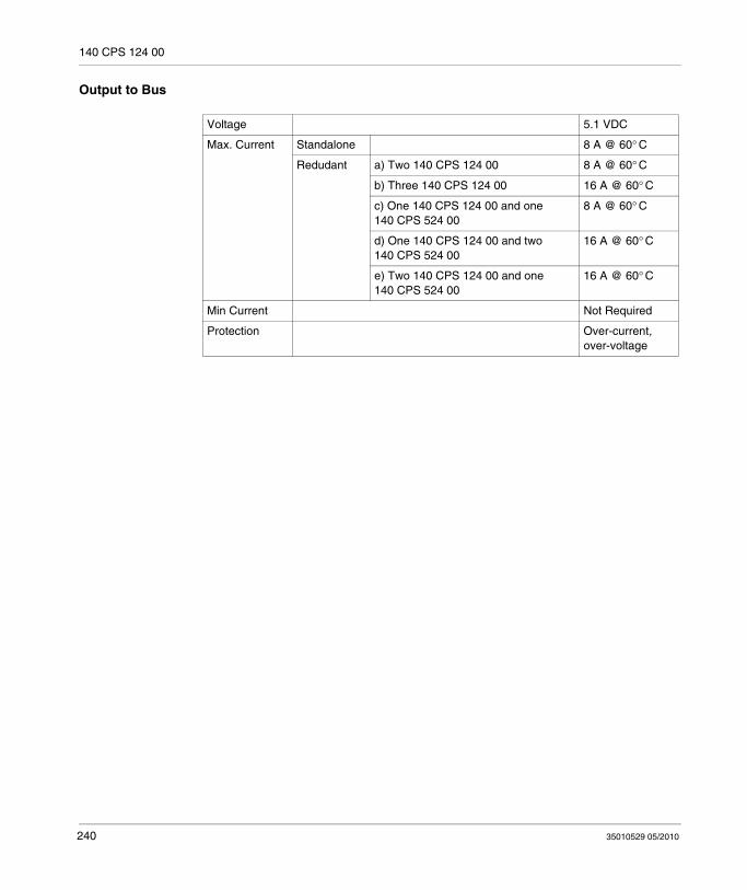
140 CPS 124 00
Output to Bus
Voltage 5.1 VDC
Max. Current Standalone 8 A @ 60° C
Redudant a) Two 140 CPS 124 00 8 A @ 60° C
b) Three 140 CPS 124 00 16 A @ 60° C
c) One 140 CPS 124 00 and one 140 CPS 524 00
8 A @ 60° C
d) One 140 CPS 124 00 and two 140 CPS 524 00
16 A @ 60° C
e) Two 140 CPS 124 00 and one 140 CPS 524 00
16 A @ 60° C
Min Current Not Required
Protection Over-current, over-voltage
240 35010529 05/2010

35010529 05/2010
18
140 CPS 124 20
35010529 05/2010
140 CPS 124 20: 115/230 VAC Standalone/Redundant 11 A Power Supply Module
Purpose
This chapter provides information on the 140 CPS 124 20 Power Supply module.
What's in this Chapter?
This chapter contains the following topics:
Topic Page
140 CPS 124 20 Wiring Diagram 242
140 CPS 124 20 Specifications 243
241
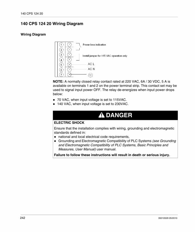
140 CPS 124 20
140 CPS 124 20 Wiring Diagram
Wiring Diagram
NOTE: A normally closed relay contact rated at 220 VAC, 6A / 30 VDC, 5 A is available on terminals 1 and 2 on the power terminal strip. This contact set may be used to signal input power OFF. The relay de-energizes when input power drops below:
70 VAC, when input voltage is set to 115VAC.140 VAC, when input voltage is set to 230VAC.
DANGERELECTRIC SHOCK
Ensure that the installation complies with wiring, grounding and electromagnetic standards defined in:
national and local electrical code requirements,Grounding and Electromagnetic Compatibility of PLC Systems (see Grounding and Electromagnetic Compatibility of PLC Systems, Basic Principles and Measures, User Manual) user manual.
Failure to follow these instructions will result in death or serious injury.
242 35010529 05/2010

140 CPS 124 20
140 CPS 124 20 Specifications
General Specifications
140 CPS 124 20 power supplies are designed to not require the external EMI filter, ferrite bead and Olflex cable.
Input
Operating mode Standalone
Redundant
Internal power dissipation (electric losses)
11 W
Network power consumption Electric losses + (5.1 x Iout)1
Power factor 0.5
1: Iout: sum of currents consumption by all modules in rack (in A)
Input voltage 93 ... 138 VAC
170 ... 263 VAC
Input frequency 47 ... 63 Hz
Input voltage total harmonic distortion
Less than 10% of the fundamental rms value
Input current 1.2 A @ 115 VAC
0.7 A @ 230 VAC
Inrush current ≤20 A @ 115 VAC
≤25 A @ 230 VAC
VA Rating 160 VA @ 11 A
Fusing (external) 2.0 A slow-blow
Input power interruption 1/2 cycle @ full load and minimum rated line voltage / frequency. No less than 1 s between interruptions.
35010529 05/2010 243

140 CPS 124 20
Output to Bus
Voltage 5.1 VDC
Max. Current Standalone 11 A @ 60° C
Redundant a) Two 140 CPS 124 20 10 A @ 60° C
b) Three 140 CPS 124 20 20 A @ 60° C
c) One 140 CPS 124 20 and one 140 CPS x24 00
6 A @ 60° C
9 A @ 40° C
d) One 140 CPS 124 20 and two 140 CPS x24 00
12 A @ 60° C
18 A @ 40° C
e) Two 140 CPS 124 20 and one 140 CPS x24 00
16 A @ 60° C
19 A @ 40° C
140 CPS x24 00 means 140 CPS 224 00 or 140 CPS 424 00.
Min. current Not required
Protection Over-current, over-voltage
244 35010529 05/2010
35010529 05/2010
19
140 CPS 211 00
35010529 05/2010
140 CPS 211 00: 24 VDC Standalone 3 A Power Supply Module
Purpose
This chapter provides information on the 140 CPS 211 00 Power Supply module.
What's in this Chapter?
This chapter contains the following topics:
Topic Page
140 CPS 211 00 Wiring Diagram 246
140 CPS 211 00 Specifications 247
245

140 CPS 211 00
140 CPS 211 00 Wiring Diagram
Wiring Diagram
DANGERELECTRIC SHOCK
Ensure that the installation complies with wiring, grounding and electromagnetic standards defined in:
national and local electrical code requirements,Grounding and Electromagnetic Compatibility of PLC Systems (see Grounding and Electromagnetic Compatibility of PLC Systems, Basic Principles and Measures, User Manual) user manual.
Failure to follow these instructions will result in death or serious injury.
246 35010529 05/2010
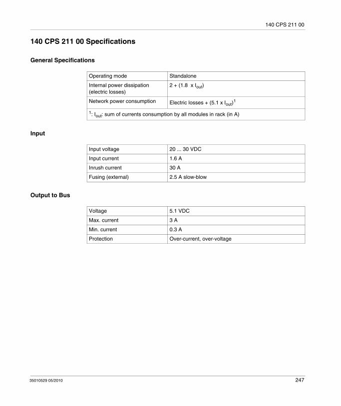
140 CPS 211 00
140 CPS 211 00 Specifications
General Specifications
Input
Output to Bus
Operating mode Standalone
Internal power dissipation (electric losses)
2 + (1.8 x Iout)
Network power consumption Electric losses + (5.1 x Iout)1
1: Iout: sum of currents consumption by all modules in rack (in A)
Input voltage 20 ... 30 VDC
Input current 1.6 A
Inrush current 30 A
Fusing (external) 2.5 A slow-blow
Voltage 5.1 VDC
Max. current 3 A
Min. current 0.3 A
Protection Over-current, over-voltage
35010529 05/2010 247

140 CPS 211 00
248 35010529 05/2010

35010529 05/2010
20
140 CPS 214 00
35010529 05/2010
140 CPS 214 00: 24 VDC Standalone/Summable 7–8 A Power Supply Module
Purpose
This chapter provides information on the 140 CPS 214 00 Power Supply module.
What's in this Chapter?
This chapter contains the following topics:
Topic Page
140 CPS 214 00 Wiring Diagram 250
140 CPS 214 00 Specifications 251
249

140 CPS 214 00
140 CPS 214 00 Wiring Diagram
Wiring Diagram
NOTE: 1. A normally closed relay contact rated at 220 VAC, 6 A / 30 VDC, 5 A is available on terminals 1 and 2 on the power terminal strip. This contact set may be used to signal input power OFF. The relay de-energizes when input power drops below 18 VDC.
2. Tolerance to input interruptions may be increased by adding a ≥50 VDC electrolytic capacitor between terminals 5 and 6 on the power terminal strip. Refer to the hold-up capacitor timing chart for capacitor values Input, page 251.
DANGERELECTRIC SHOCK
Ensure that the installation complies with wiring, grounding and electromagnetic standards defined in:
national and local electrical code requirements,Grounding and Electromagnetic Compatibility of PLC Systems (see Grounding and Electromagnetic Compatibility of PLC Systems, Basic Principles and Measures, User Manual) user manual.
Failure to follow these instructions will result in death or serious injury.
250 35010529 05/2010

140 CPS 214 00
140 CPS 214 00 Specifications
General Specifications
Input
Operating mode Standalone
Summable
Internal power dissipation (electric losses)
5 + (1.25 x Iout)
Network power consumption Electric losses + (5.1 x Iout)1
1: Iout: sum of currents consumption by all modules in rack (in A)
Input voltage 20 ... 30 VDC
Input current 3.8 A
Inrush current 25 A @ 24 VDC
14 A @ 20 VDC
Input ripple 2.4 VDC peak-to-peak, 94 ... 189 Hz
Input power interruption 1 ms max. @ 24 VDCHold-up capacitor timing chart
Fusing (external) 5.0 A slow-blow
35010529 05/2010 251
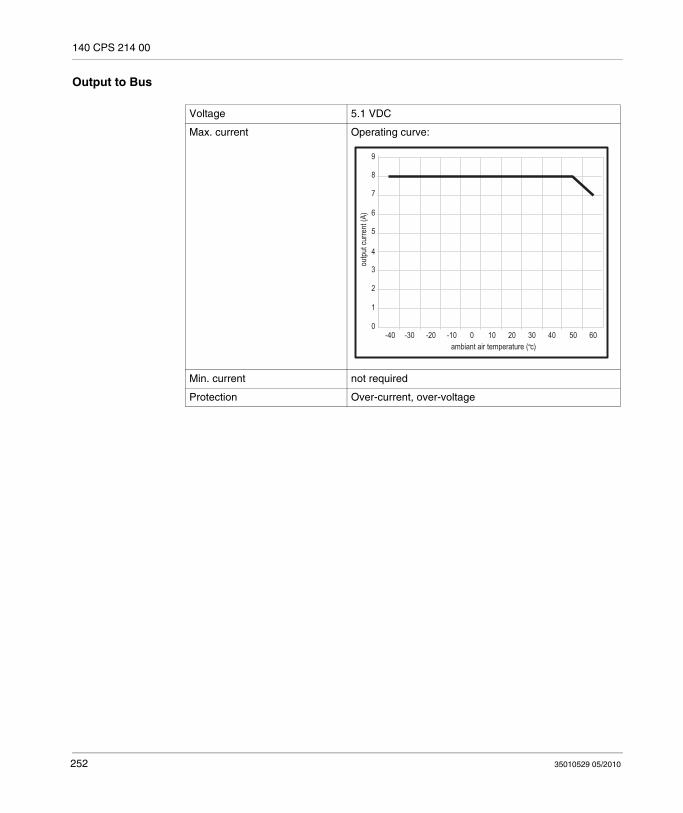
140 CPS 214 00
Output to Bus
Voltage 5.1 VDC
Max. current Operating curve:
Min. current not required
Protection Over-current, over-voltage
9
8
7
6
5
4
3
2
1
0-40 -30 -20 -10 0 10 20 30 40 50 60
ambiant air temperature ( c)
outp
ut cu
rrent
(A)
252 35010529 05/2010

35010529 05/2010
21
140 CPS 224 00
35010529 05/2010
140 CPS 224 00: 24 VDC Standalone/Redundant 6–9 A Power Supply Module
Purpose
This chapter provides information on the 140 CPS 224 00 Power Supply module.
What's in this Chapter?
This chapter contains the following topics:
Topic Page
140 CPS 224 00 Wiring Diagram 254
140 CPS 224 00 Specifications 255
253
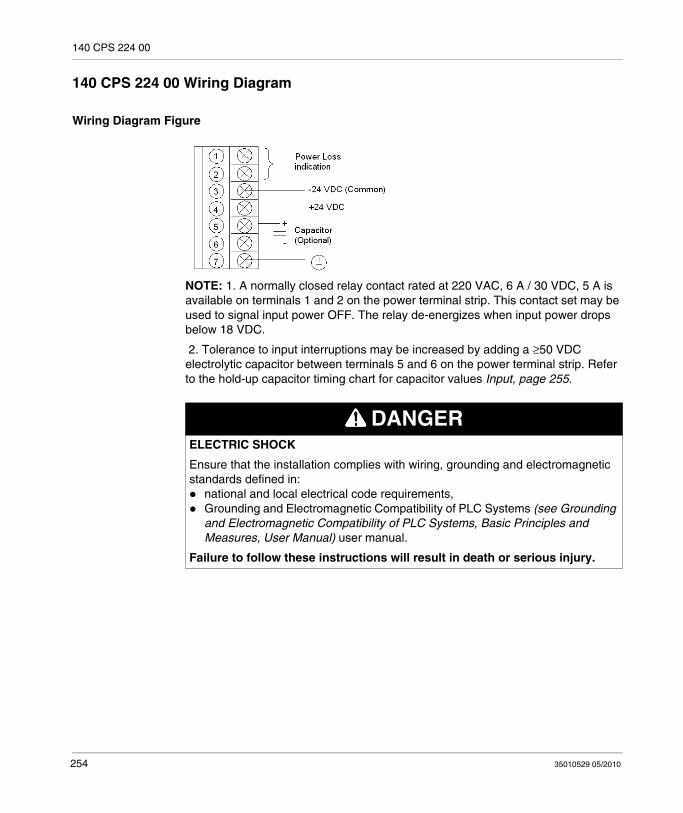
140 CPS 224 00
140 CPS 224 00 Wiring Diagram
Wiring Diagram Figure
NOTE: 1. A normally closed relay contact rated at 220 VAC, 6 A / 30 VDC, 5 A is available on terminals 1 and 2 on the power terminal strip. This contact set may be used to signal input power OFF. The relay de-energizes when input power drops below 18 VDC.
2. Tolerance to input interruptions may be increased by adding a ≥50 VDC electrolytic capacitor between terminals 5 and 6 on the power terminal strip. Refer to the hold-up capacitor timing chart for capacitor values Input, page 255.
DANGERELECTRIC SHOCK
Ensure that the installation complies with wiring, grounding and electromagnetic standards defined in:
national and local electrical code requirements,Grounding and Electromagnetic Compatibility of PLC Systems (see Grounding and Electromagnetic Compatibility of PLC Systems, Basic Principles and Measures, User Manual) user manual.
Failure to follow these instructions will result in death or serious injury.
254 35010529 05/2010

140 CPS 224 00
140 CPS 224 00 Specifications
General Specifications
Input
Operating mode Standalone
Redundant
Internal power dissipation (in W) 7 + (1.5 x Iout 1)
Network power consumption Electric losses + (5.1 x Iout)
1: Iout: sum of currents consumption by all modules in rack (in A)
Input voltage 20 ... 30 VDC
Input current 3.8 A
Inrush current 25 A @ 24 VDC
14 A @ 20 VDC
Input ripple 2.4 VDC peak-to-peak, 94 ... 189 Hz
Input Power Interruption 1 ms max. @ 24 VDCHold-up capacitor timing chart
Fusing (external) 5.0 A slow-blow
35010529 05/2010 255

140 CPS 224 00
Output to Bus
Voltage 5.1 VDC
Max. Current
Standalone Operating curve: 6 A @ 60° C9 A @ 40° C
Redundant a) Two 140 CPS x24 20 6 A @ 60° C
9 A @ 40° C
b) Three 140 CPS x24 00 12 A @ 60° C
18 A @ 40° C
c) One 140 CPS 224 00 and one 140 CPS x24 00
6 A @ 60° C
9 A @ 40° C
d) One 140 CPS 224 00 and two 140 CPS x24 00
12 A @ 60° C
18 A @ 40° C
e) Two 140 CPS 224 00 and one 140 CPS x24 00
16 A @ 60° C
19 A @ 40° C
140 CPS x24 00 means 140 CPS 224 00 or 140 CPS 424 00.
Protection Over-current, over-voltage
Surge withland
2.3 x max. rated input voltage for 1.3ms
256 35010529 05/2010

35010529 05/2010
22
140 CPS 414 00
35010529 05/2010
140 CPS 414 00: 48 VDC Standalone/Summable 7–8 A Power Supply Module
Purpose
This chapter provides information on the 140 CPS 414 00 Power Supply module.
What's in this Chapter?
This chapter contains the following topics:
Topic Page
140 CPS 414 00 Wiring Diagram 258
140 CPS 414 00 Specifications 259
257

140 CPS 414 00
140 CPS 414 00 Wiring Diagram
Wiring Diagram Figure
NOTE: 1. A normally closed relay contact rated at 220 VAC, 6 A / 30 VDC, 5 A is available on terminals 1 and 2 on the power terminal strip. This contact set may be used to signal input power OFF or a power supply loss. The relay de-energizes when input power drops below 35 VDC.
2. Tolerance to input interruptions may be increased by adding a ≥80 VDC electrolytic capacitor between terminals 5 and 6 on the power terminal strip. Refer to the hold-up capacitor timing chart for capacitor values in the specification Input, page 259.
DANGERELECTRIC SHOCK
Ensure that the installation complies with wiring, grounding and electromagnetic standards defined in:
national and local electrical code requirements,Grounding and Electromagnetic Compatibility of PLC Systems (see Grounding and Electromagnetic Compatibility of PLC Systems, Basic Principles and Measures, User Manual) user manual.
Failure to follow these instructions will result in death or serious injury.
258 35010529 05/2010

140 CPS 414 00
140 CPS 414 00 Specifications
General Specifications
Input
Operating mode Standalone
Summable
Internal power dissipation (in W) 6 + (1.0 x Iout)
Network power consumption Electric losses + (5.1 x Iout)1
1: Iout: sum of currents consumption by all modules in rack (in A)
Input voltage 48 ... 72 VDC
Input current 1.2 A @ 48 VDC
Inrush current 25 A @ 40 VDC
Input power interruption 13 ms max. @ 48 VDCHold-up capacitor timing chart:
Fusing (external) 2.0 A medium time-lag
35010529 05/2010 259
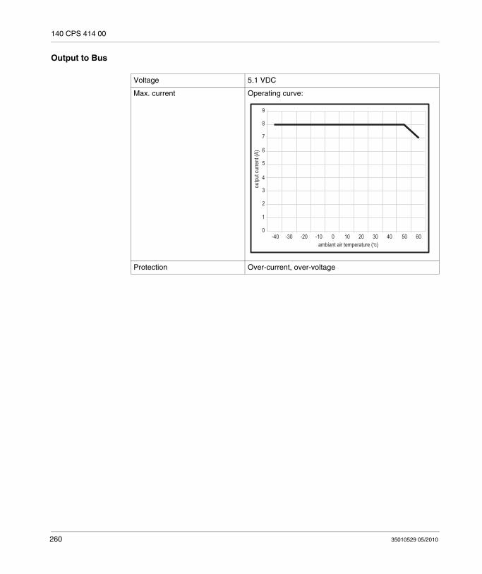
140 CPS 414 00
Output to Bus
Voltage 5.1 VDC
Max. current Operating curve:
Protection Over-current, over-voltage
9
8
7
6
5
4
3
2
1
0-40 -30 -20 -10 0 10 20 30 40 50 60
ambiant air temperature ( c)
outp
ut cu
rrent
(A)
260 35010529 05/2010
35010529 05/2010
23
140 CPS 424 00
35010529 05/2010
140 CPS 424 00: 48 VDC Standalone/Redundant 6–9 A Power Supply Module
Purpose
This chapter provides information on the 140 CPS 424 00 Power Supply module.
What's in this Chapter?
This chapter contains the following topics:
Topic Page
140 CPS 424 00 Wiring Diagram 262
140 CPS 424 00 Specifications 263
261
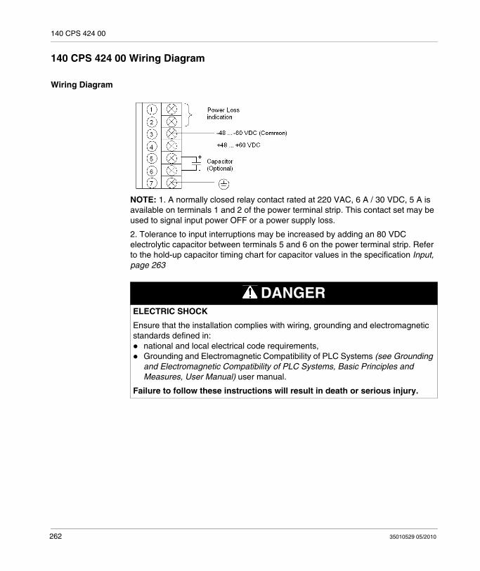
140 CPS 424 00
140 CPS 424 00 Wiring Diagram
Wiring Diagram
NOTE: 1. A normally closed relay contact rated at 220 VAC, 6 A / 30 VDC, 5 A is available on terminals 1 and 2 of the power terminal strip. This contact set may be used to signal input power OFF or a power supply loss.
2. Tolerance to input interruptions may be increased by adding an 80 VDC electrolytic capacitor between terminals 5 and 6 on the power terminal strip. Refer to the hold-up capacitor timing chart for capacitor values in the specification Input, page 263
DANGERELECTRIC SHOCK
Ensure that the installation complies with wiring, grounding and electromagnetic standards defined in:
national and local electrical code requirements,Grounding and Electromagnetic Compatibility of PLC Systems (see Grounding and Electromagnetic Compatibility of PLC Systems, Basic Principles and Measures, User Manual) user manual.
Failure to follow these instructions will result in death or serious injury.
262 35010529 05/2010

140 CPS 424 00
140 CPS 424 00 Specifications
General Specifications
Input
Operating mode Standalone
Redundant
Internal power dissipation (in W) 7 + (1.5 x Iout)1
Network power consumption Electric losses + (5.1 x Iout)
1: Iout: sum of currents consumption by all modules in rack (in A)
Input voltage 48 ... 72 VDC
Input current 1.3 A @ 48 VDC
Inrush current 25 A @ 48 VDC
Input power interruption 13 ms max. @ 48 VDCHold-up capacitor timing chart:
Fusing (external) 2.0 A medium time-lag
35010529 05/2010 263
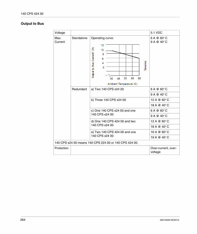
140 CPS 424 00
Output to Bus
Voltage 5.1 VDC
Max. Current
Standalone Operating curve: 6 A @ 60° C9 A @ 40° C
Redundant a) Two 140 CPS x24 20 6 A @ 60° C
9 A @ 40° C
b) Three 140 CPS x24 00 12 A @ 60° C
18 A @ 40° C
c) One 140 CPS x24 00 and one 140 CPS x24 00
6 A @ 60° C
9 A @ 40° C
d) One 140 CPS 424 00 and two 140 CPS x24 00
12 A @ 60° C
18 A @ 40° C
e) Two 140 CPS 424 00 and one 140 CPS x24 00
16 A @ 60° C
19 A @ 40° C
140 CPS x24 00 means 140 CPS 224 00 or 140 CPS 424 00.
Protection Over-current, over-voltage
264 35010529 05/2010
35010529 05/2010
24
140 CPS 511 00
35010529 05/2010
140 CPS 511 00: 125 VDC Standalone 3 A Power Supply Module
Purpose
This chapter provides information on the 140 CPS 511 00 Power Supply module.
What's in this Chapter?
This chapter contains the following topics:
Topic Page
140 CPS 511 00 Wiring Diagram 266
140 CPS 511 00 Specifications 267
265

140 CPS 511 00
140 CPS 511 00 Wiring Diagram
Wiring Diagram
DANGERELECTRIC SHOCK
Ensure that the installation complies with wiring, grounding and electromagnetic standards defined in:
national and local electrical code requirements,Grounding and Electromagnetic Compatibility of PLC Systems (see Grounding and Electromagnetic Compatibility of PLC Systems, Basic Principles and Measures, User Manual) user manual.
Failure to follow these instructions will result in death or serious injury.
266 35010529 05/2010

140 CPS 511 00
140 CPS 511 00 Specifications
General Specifications
Input
Output to Bus
Operating mode Standalone
Internal power dissipation (in W) 2 + (1.8 x Iout)1
Network power consumption Electric losses + (5.1 x Iout)
1: Iout: sum of currents consumption by all modules in rack (in A)
Input voltage 100 ... 150 VDC (including ripple)
Input current 0.4 A
Inrush current 10 A
Input power interruption 1 ms max.
Fusing (external) 1.5 A slow-blow
Voltage 5.1 VDC
Max. current 3 A
Protection Over-current, over-voltage
35010529 05/2010 267

140 CPS 511 00
268 35010529 05/2010

35010529 05/2010
25
140 CPS 524 00
35010529 05/2010
140 CPS 524 00: 125 VDC Standalone/Redundant 8 A Power Supply Module
Purpose
This chapter provides information on the 140 CPS 524 00 Power Supply module.
What's in this Chapter?
This chapter contains the following topics:
Topic Page
140 CPS 524 00 Wiring Diagram 270
140 CPS 524 00 Specifications 271
269
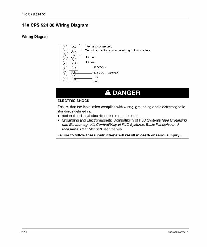
140 CPS 524 00
140 CPS 524 00 Wiring Diagram
Wiring Diagram
DANGERELECTRIC SHOCK
Ensure that the installation complies with wiring, grounding and electromagnetic standards defined in:
national and local electrical code requirements,Grounding and Electromagnetic Compatibility of PLC Systems (see Grounding and Electromagnetic Compatibility of PLC Systems, Basic Principles and Measures, User Manual) user manual.
Failure to follow these instructions will result in death or serious injury.
270 35010529 05/2010
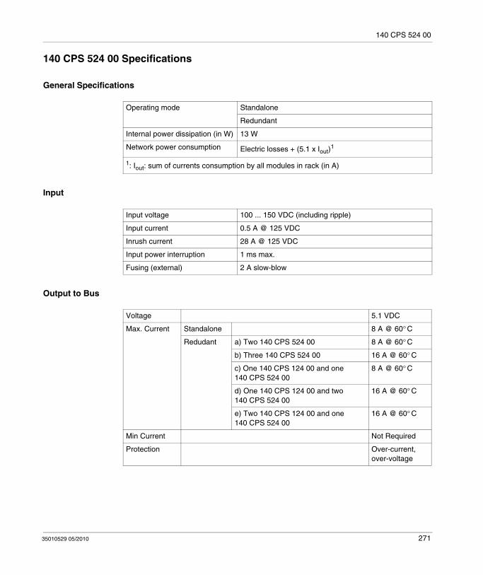
140 CPS 524 00
140 CPS 524 00 Specifications
General Specifications
Input
Output to Bus
Operating mode Standalone
Redundant
Internal power dissipation (in W) 13 W
Network power consumption Electric losses + (5.1 x Iout)1
1: Iout: sum of currents consumption by all modules in rack (in A)
Input voltage 100 ... 150 VDC (including ripple)
Input current 0.5 A @ 125 VDC
Inrush current 28 A @ 125 VDC
Input power interruption 1 ms max.
Fusing (external) 2 A slow-blow
Voltage 5.1 VDC
Max. Current Standalone 8 A @ 60° C
Redudant a) Two 140 CPS 524 00 8 A @ 60° C
b) Three 140 CPS 524 00 16 A @ 60° C
c) One 140 CPS 124 00 and one 140 CPS 524 00
8 A @ 60° C
d) One 140 CPS 124 00 and two 140 CPS 524 00
16 A @ 60° C
e) Two 140 CPS 124 00 and one 140 CPS 524 00
16 A @ 60° C
Min Current Not Required
Protection Over-current, over-voltage
35010529 05/2010 271

140 CPS 524 00
272 35010529 05/2010
35010529 05/2010
IV
Rack
35010529 05/2010
Racks(XBP) and Rack Expander (XBE)
Introduction
This part provides information on the Quantum racks and rack expander.
What's in this Part?
This part contains the following chapters:
Chapter Chapter Name Page
26 Selecting Racks (XBP) 275
27 140 XBE 100 00: Rack Expander 283
273

Rack
274 35010529 05/2010
35010529 05/2010
26
Selecting Racks
35010529 05/2010
Selecting Racks (XBP)
Purpose
This chapter provides information on selecting Quantum Racks.
What's in this Chapter?
This chapter contains the following topics:
Topic Page
General Information 276
140 XBP 002 00: Two Position Rack 277
140 XBP 003 00: Three Position Rack 278
140 XBP 004 00: Four Position Rack 279
140 XBP 006 00: Six Position Rack 280
140 XBP 010 00: Ten Position Rack 281
140 XBP 016 00: Sixteen Position Rack 282
275

Selecting Racks
General Information
Overview
Racks are designed to mechanically fasten and electrically connect modules used in drops. The rack contains a passive circuit board which permits modules to communicate with each other and to identify their slot numbers without further switch settings.
NOTE: To meet vibration/shock specifications, the rack must be mounted using all specified mounting holes. The rack is mounted using standard hardware (described below).
The recommended length for the mounting screws should be within the following range: 0.24 in. (6 mm) - 0.52 in. (13 mm)
The head height of the screws should not exceed 0.14 in. (3.5 mm).
276 35010529 05/2010

Selecting Racks
140 XBP 002 00: Two Position Rack
Two Position Rack
A 290 mm (11.42 in)B 270 mm (10.63 in)C 175.5 mm (6.91 in)D 94.5 mm (3.72 in)E 10 mm (0.39 in)F 15 mm (0.59 in)G 102.61 mm (4.04 in)H 72.44 mm (2.85 in)
35010529 05/2010 277
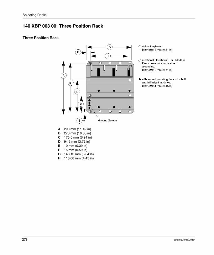
Selecting Racks
140 XBP 003 00: Three Position Rack
Three Position Rack
A 290 mm (11.42 in)B 270 mm (10.63 in)C 175.5 mm (6.91 in)D 94.5 mm (3.72 in)E 10 mm (0.39 in)F 15 mm (0.59 in)G 143.13 mm (5.64 in)H 113.08 mm (4.45 in)
278 35010529 05/2010
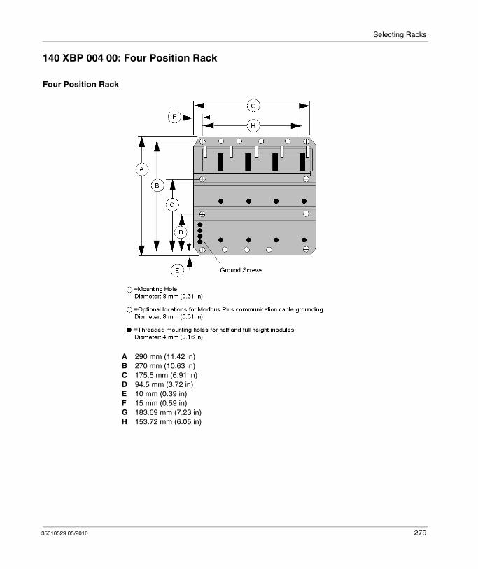
Selecting Racks
140 XBP 004 00: Four Position Rack
Four Position Rack
A 290 mm (11.42 in)B 270 mm (10.63 in)C 175.5 mm (6.91 in)D 94.5 mm (3.72 in)E 10 mm (0.39 in)F 15 mm (0.59 in)G 183.69 mm (7.23 in)H 153.72 mm (6.05 in)
35010529 05/2010 279
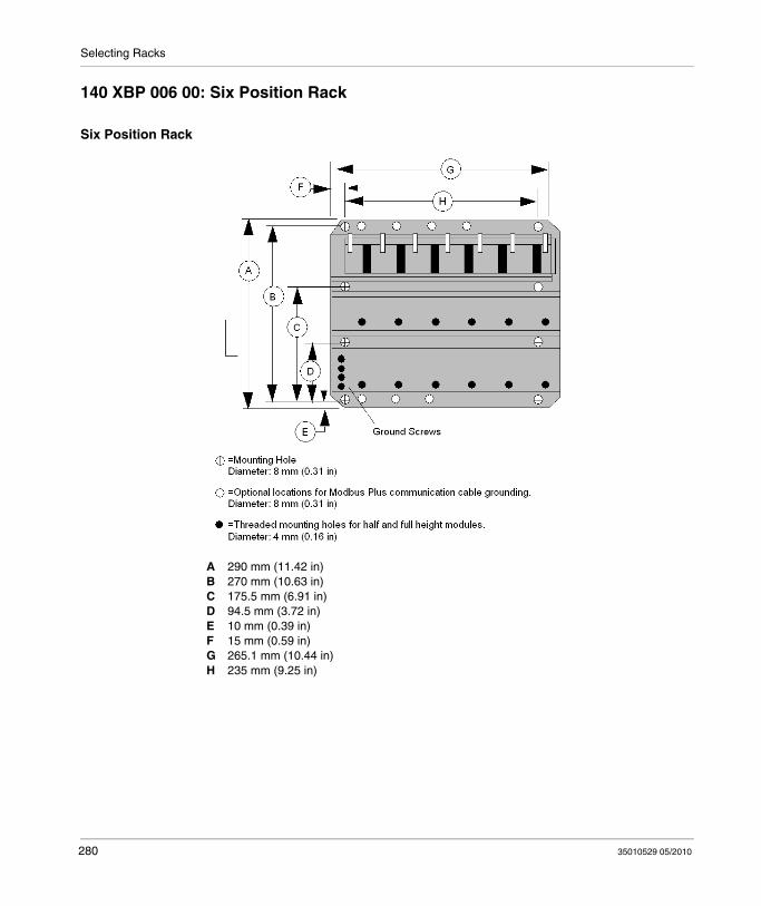
Selecting Racks
140 XBP 006 00: Six Position Rack
Six Position Rack
A 290 mm (11.42 in)B 270 mm (10.63 in)C 175.5 mm (6.91 in)D 94.5 mm (3.72 in)E 10 mm (0.39 in)F 15 mm (0.59 in)G 265.1 mm (10.44 in)H 235 mm (9.25 in)
280 35010529 05/2010

Selecting Racks
140 XBP 010 00: Ten Position Rack
Ten Position Rack
A 290 mm (11.42 in)B 270 mm (10.63 in)C 175.5 mm (6.91 in)D 94.5 mm (3.72 in)E 10 mm (0.39 in)F 15 mm (0.59 in)G 427.66 mm (16.84 in)H 397.56 mm (15.65 in)I 198.78 mm (7.82 in)
35010529 05/2010 281
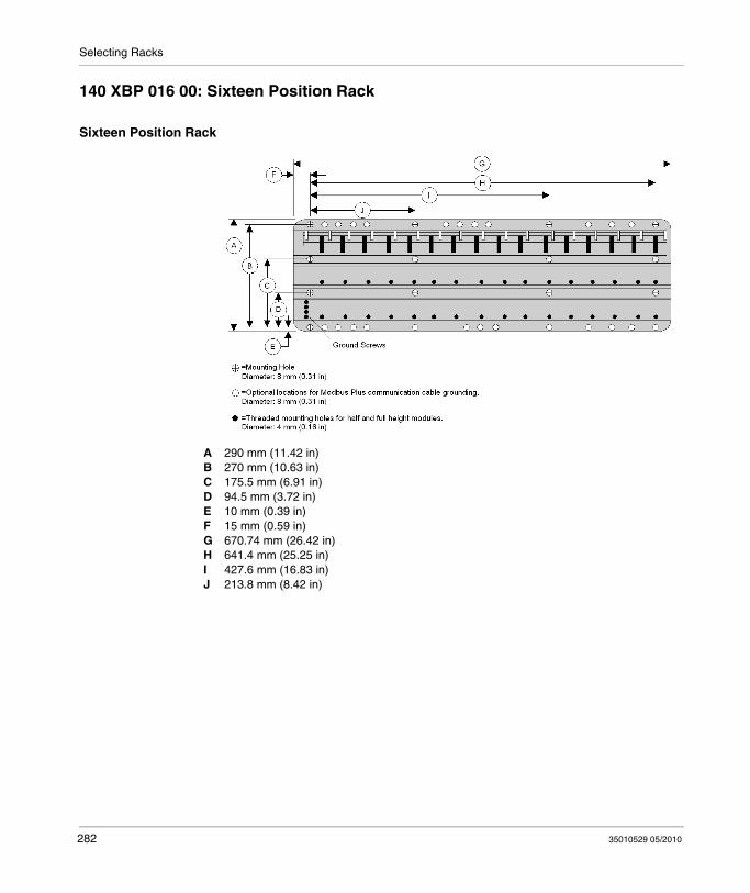
Selecting Racks
140 XBP 016 00: Sixteen Position Rack
Sixteen Position Rack
A 290 mm (11.42 in)B 270 mm (10.63 in)C 175.5 mm (6.91 in)D 94.5 mm (3.72 in)E 10 mm (0.39 in)F 15 mm (0.59 in)G 670.74 mm (26.42 in)H 641.4 mm (25.25 in)I 427.6 mm (16.83 in)J 213.8 mm (8.42 in)
282 35010529 05/2010
35010529 05/2010
27
140 XBE 100 00
35010529 05/2010
140 XBE 100 00: Rack Expander
Purpose
This chapter provides information on the 140 XBE 100 00 module.
What's in this Chapter?
This chapter contains the following topics:
Topic Page
General Information 284
Presentation 286
Operation Guidelines 287
140 XBE 100 00 Specifications 289
283

140 XBE 100 00
General Information
Function
The Rack Expander acts as a repeater for data signals from a primary Quantum rack. Since power is not provided to the secondary rack over the expander cable, power supplies are required in both racks.
The Rack Expander does not have any LEDs to display its status. The active LEDs of the modules in the secondary rack and their associated diagnostic status bits indicate proper operation, including the Rack Expander.
Basic Configuration
The rack containing the CPU or RIO drop adapter is called the Primary rack, and the adjacent rack is designated as the Secondary rack. Each rack requires its own power supply.
1 Power Supplies2 CPU or RIO Adapter3 First Rack Expander (140 XBE 100 00)4 Second Rack Expander (140 XBE 100 00)5 Rack Expander Cable (140 XCA 717 0•)6 Cable end marked as "Primary"
NOTE: Install the cable when the racks are powered OFF.
284 35010529 05/2010

140 XBE 100 00
Features
Enhances system performance requiring fewer remote I/O drops for the CPU to service.Enables a Quantum CPU to handle up to 27,648 discrete I/O.Makes it easy to plan for future I/O expansion by leaving an I/O slot empty for module insertion.Cost effective for local I/O by eliminating the need for a remote I/O head and drop.Cost effective by eliminating the need for an additional remote I/O drop.
Part Numbers
The following table provides necessary part numbers.
CAUTIONUNINTENDED EQUIPMENT OPERATION
The communication cable is polarized. The cable end marked "Primary" must be connected to the rack that includes the CPU or RIO adapter.The communications cable must be connected to the Rack Expander module before it is hot swapped into a powered rack.Do not hot swap Rack Expanders modules while modules in secondary rack are operating.
Failure to follow these instructions can result in injury or equipment damage.
Rack Expander 140 XBE 100 00
Rack Expander (conformally coated) 140 XBE 100 00C
Expander Cable, 3' (1 m) 140 XCA 717 03
Expander Cable, 6' (2 m) 140 XCA 717 06
Expander Cable, 9' (3 m) 140 XCA 717 09
35010529 05/2010 285

140 XBE 100 00
Presentation
Function
With the 140 XBE 100 00 Rack Expander you can add a second rack to a local or remote drop. A custom communications cable, 3.0 m (9.84 ft) maximum, provides the data communication transfer.
Rack Expander
1 Module number, module description and color code2 Connector3 Removable door
286 35010529 05/2010

140 XBE 100 00
Operation Guidelines
Rack Expander Guidelines
The same 140 XBE 100 00 Rack Expander modules are used for the primary and secondary racks. The end of the Rack Expander cable marked "Primary" always connects to the Rack Expander module in the primary rack.The system can use any Quantum type power supply. Each rack can have a different type of power supply.Loss of power in the secondary rack will not shut down the entire drop. Only modules located in the "Secondary" rack will lose power.Rack expander modules can be located in any slot in the rack and do not have to be placed in corresponding slots in the primary and secondary racks.I/O modules that have downloadable executive firmware, such as the ESI module, are allowed in the secondary rack—except when downloading their execs. Executive firmware cannot be downloaded to modules in the secondary rack.It may be necessary to update the CPU or RIO drop executive firmware. See the Executive Firmware section in Specifications.The Rack Expander will not be recognized by the programming panel software. It will look like an unfilled slot in the PLC I/O map.The Rack Expander will allow configuration or I/O mapping of additional modules in the local drop containing a CPU or RIO drop adapter—up to the drop word limit or physical slot address limitation.Option modules, such as NOMs, NOEs and CHSs must reside in the primary rack.Any Interrupt module can be located in the secondary rack, but the interrupt mode is not supported.
35010529 05/2010 287
140 XBE 100 00
If the primary rack power supply goes OFF, and the secondary rack power supply remains ON, the behavior of the outputs on the secondary rack is not guaranteed. Outputs could either go to the Off state or adopt their Timeout state as defined by the user.
If the power supply of the secondary rack goes OFF, and the primary rack power supply remains ON, the I/O Health bit of the modules located in this rack could indicate a healthy module.
CAUTIONUNINTENDED EQUIPMENT OPERATION - UNKNOWN OUTPUT STATE
The Timeout State must be configured as USER DEFINED with a VALUE of 0 for all modules in the secondary rack regardless of the configuration.The same primary power source must be used for the primary and secondary racks.
Failure to follow these instructions can result in injury or equipment damage.
288 35010529 05/2010

140 XBE 100 00
140 XBE 100 00 Specifications
General Specifications
Compatibility
Max. Words/Drop
Number of connected racks 2
Maximum distance 3 m
rack requirements For rack sizes (3-, 4-, 6-, 10- and 16-slot)
Slots used 1
Number of rack expander modules allowed
1/rack
LEDs None
Required addressing The rack expander looks like an unfilled slot in the PLC I/O map.
Power consumption 2.5 W
Bus current required 500 mA
Connector 3-pin D-type
Primary rack No restrictions
Secondary rack Quantum I/O modules can be used in the secondary rack, unless otherwise noted in the I/O documentation.
Executive firmware 140 CPU •13 0• - Version 2.2
140 CPU •34 1• - Version 1.03
140 CPU •34 1•A - Any version
140 CPU 424 02 - Version 2.15
140 CPU 6•1 •0 - Any version
140 CRA 93• 0• - Version 1.2
Local I/O 64 in / 64 outNote:For Unity CPU (for example 140 CPU 65150) there is no limitation of I/O words on local rack.
Remote I/O 64 in / 64 out
35010529 05/2010 289

140 XBE 100 00
290 35010529 05/2010
35010529 05/2010
V
Simulator and Battery Modules
35010529 05/2010
Simulator (XSM) and Battery (XCP) Module
Introduction
This part provides information on Quantum Simulator (XSM) and Battery (XCP) Module.
What's in this Part?
This part contains the following chapters:
Chapter Chapter Name Page
28 Simulator Modules (XSM) 293
29 140 XCP 900 00: Battery Module 299
291

Simulator and Battery Modules
292 35010529 05/2010

35010529 05/2010
28
Simulator Modules
35010529 05/2010
Simulator Modules (XSM)
Purpose
This chapter provides information on Quantum Simulator Modules (XSM).
What's in this Chapter?
This chapter contains the following sections:
Section Topic Page
28.1 140 XSM 010 00: Two Channels In / One Channel Out Analog Simulator
294
28.2 140 XSM 002 00: 16 Point Discrete Input Simulator 298
293
Simulator Modules
28.1 140 XSM 010 00: Two Channels In / One Channel Out Analog Simulator
Purpose
This section provides information on the 140 XSM 010 00 analog simulator.
What's in this Section?
This section contains the following topics:
Topic Page
Presentation 295
140 XSM 010 00 Wiring Diagram 296
140 XSM 010 00 Specifications 297
294 35010529 05/2010

Simulator Modules
Presentation
Function
The 140 XSM 010 00 module simulates 4 ... 20 mA field current loops. It provides two adjustable 4 ... 20 mA analog signals and one fixed 24 VDC output. The simulator also measures and displays voltages from 0 ... 5 VDC.
The simulator module includes the following:
An internal 24 VDC power supply
A 0 ... 5 VDC meter
Two 10-turn potentiometers
NOTE: The 140 XSM 010 00 is not a field-operational module. It should be used only for testing, simulating and calibrating Quantum current input modules.
Illustration
1 Model number, module description, color code2 LED display3 Voltmeter4 Potentiometers5 Color-coded leads6 Removable door
NOTE: The 140 XSM 010 00 can be placed in any slot in the Quantum.
35010529 05/2010 295

Simulator Modules
140 XSM 010 00 Wiring Diagram
Sample Wiring Diagram
The following diagram shows a typical connection between the simulator, a 140 ACI 030 00 input module and a 140 ACO 020 00 output module. The simulator provides a variable 4 ... 20 mA input to the input module. The input can then be read by a Quantum CPU, and, if required, sent to an output module. For the output module to operate properly, the main current loop must be active, with 24 VDC supplied between terminals 9 and 10 with a 249 Ω voltage drop resistor.
NOTE: For a more detailed description of these modules, refer to the Discrete and Analog I/O Reference Manual Quantum I/O Analog IN Modules (see Quantum with Unity Pro, Discrete and Analog I/O, Reference Manual), Quantum I/O Analog OUT Modules (see Quantum with Unity Pro, Discrete and Analog I/O, Reference Manual) and Quantum I/O Analog IN / OUT Modules (see Quantum with Unity Pro, Discrete and Analog I/O, Reference Manual).
296 35010529 05/2010

Simulator Modules
140 XSM 010 00 Specifications
Specifications
Voltage Operating 100 ... 240 VAC, 50/60 Hz
Continuous output 24 VDC, 400 mA max
Operating current 300 mA @ 120 VAC
Voltmeter range 0 ... 5 VDC
10-turn potentiometer output variable current 4 ... 20 mA
variable voltage 1 ... 5 VDC
Internal fusing None
Bus current required None
35010529 05/2010 297
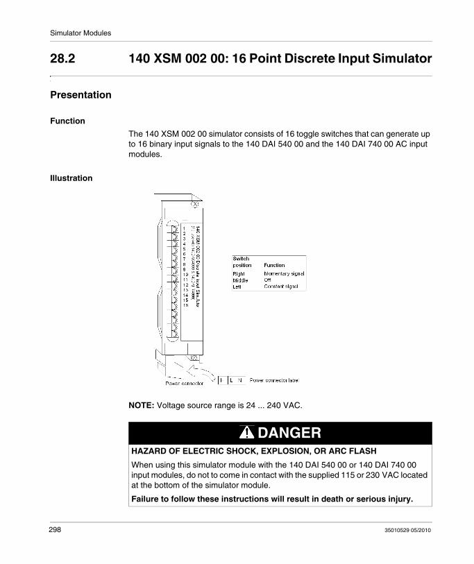
Simulator Modules
28.2 140 XSM 002 00: 16 Point Discrete Input Simulator
Presentation
Function
The 140 XSM 002 00 simulator consists of 16 toggle switches that can generate up to 16 binary input signals to the 140 DAI 540 00 and the 140 DAI 740 00 AC input modules.
Illustration
NOTE: Voltage source range is 24 ... 240 VAC.
DANGERHAZARD OF ELECTRIC SHOCK, EXPLOSION, OR ARC FLASH
When using this simulator module with the 140 DAI 540 00 or 140 DAI 740 00 input modules, do not to come in contact with the supplied 115 or 230 VAC located at the bottom of the simulator module.
Failure to follow these instructions will result in death or serious injury.
298 35010529 05/2010
35010529 05/2010
29
140 XCP 900 00
35010529 05/2010
140 XCP 900 00: Battery Module
Purpose
This chapter provides information on Quantum 140 XCP 900 00 Battery module.
What's in this Chapter?
This chapter contains the following topics:
Topic Page
Presentation 300
140 XCP 900 00 Indicators 301
Installation and Maintenance 302
140 XCP 900 00 Specifications 304
299

140 XCP 900 00
Presentation
Illustration
The following figure shows the battery module components.
1 Model Number, Module Description, Color Code2 LED Display3 Battery Slot 1 (with battery installed)4 Battery Access Tape (for removal/replacement)5 Battery Slot 2 (with battery installed)6 Battery Access Tape (for removal/replacement)7 Removable Door8 Customer Identification Label (Fold label and place it inside door)
Battery Backup
The 140 XCP 900 00 provides RAM backup power for expert modules. One non-rechargeable 3.6 V lithium battery is provided and is accessible from the front of the module in Battery Slot 1 (the upper slot) for easy removal when it is necessary to change it.
NOTE: Extended backup is provided when a second battery is installed in Battery Slot 2 (the lower slot).
300 35010529 05/2010
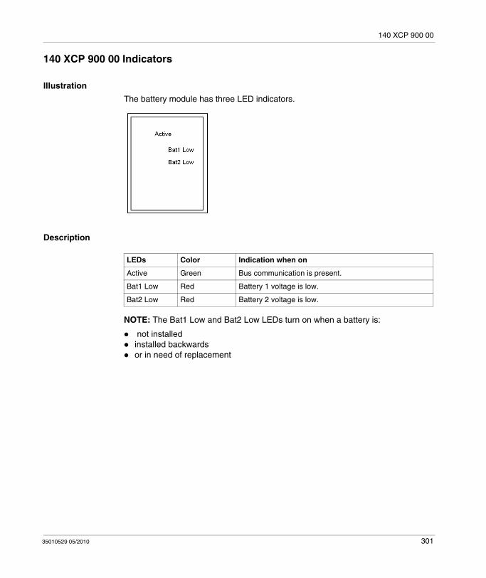
140 XCP 900 00
140 XCP 900 00 Indicators
Illustration
The battery module has three LED indicators.
Description
NOTE: The Bat1 Low and Bat2 Low LEDs turn on when a battery is:
not installedinstalled backwardsor in need of replacement
LEDs Color Indication when on
Active Green Bus communication is present.
Bat1 Low Red Battery 1 voltage is low.
Bat2 Low Red Battery 2 voltage is low.
35010529 05/2010 301

140 XCP 900 00
Installation and Maintenance
Battery Installation and Replacement Considerations
The following procedure describes the installation of a battery.
Battery
This diagram shows the battery
1 Insulating Strip2 Battery3 Access strip
Step Action
1 Remove the insulating strip from the plus (+) pole of the battery before inserting it into the module. This strip is used to insulate the battery when on the shelf.Note: The battery installed in the module, when shipped, has the insulating strip in place. Remove this strip and re-install the battery before operation.
2 When single battery backup is required, install the battery in Battery Slot 1. The circuitry is designed so Battery 1 supplies the current until it is used up. Battery 2 (when installed) then assumes the load requirement without interruption. Battery status is indicated via LEDs and status bytes.
3 When the controller is in operation, the batteries can be replaced at any time.Note: When the controller is powered OFF, battery replacement can be done without RAM loss only when a second functioning battery is installed.
302 35010529 05/2010
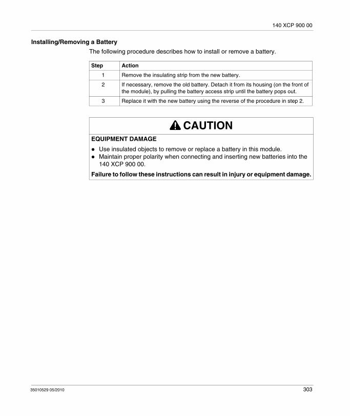
140 XCP 900 00
Installing/Removing a Battery
The following procedure describes how to install or remove a battery.
Step Action
1 Remove the insulating strip from the new battery.
2 If necessary, remove the old battery. Detach it from its housing (on the front of the module), by pulling the battery access strip until the battery pops out.
3 Replace it with the new battery using the reverse of the procedure in step 2.
CAUTIONEQUIPMENT DAMAGE
Use insulated objects to remove or replace a battery in this module.Maintain proper polarity when connecting and inserting new batteries into the 140 XCP 900 00.
Failure to follow these instructions can result in injury or equipment damage.
35010529 05/2010 303
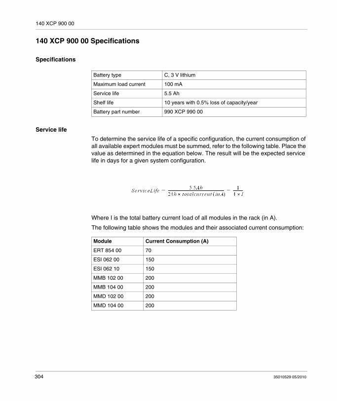
140 XCP 900 00
140 XCP 900 00 Specifications
Specifications
Service life
To determine the service life of a specific configuration, the current consumption of all available expert modules must be summed, refer to the following table. Place the value as determined in the equation below. The result will be the expected service life in days for a given system configuration.
Where I is the total battery current load of all modules in the rack (in A).
The following table shows the modules and their associated current consumption:
Battery type C, 3 V lithium
Maximum load current 100 mA
Service life 5.5 Ah
Shelf life 10 years with 0.5% loss of capacity/year
Battery part number 990 XCP 990 00
Module Current Consumption (A)
ERT 854 00 70
ESI 062 00 150
ESI 062 10 150
MMB 102 00 200
MMB 104 00 200
MMD 102 00 200
MMD 104 00 200
304 35010529 05/2010

140 XCP 900 00
Calculating Service life example
Considering that the XCP 900 00 battery box provides battery backup for the RAM ESI 062 10 and two MMB 102 00 modules.
The service life can be calculated as follow:
NOTE: If a module is operated from two batteries, the service life is also doubled.
35010529 05/2010 305

140 XCP 900 00
306 35010529 05/2010
35010529 05/2010
VI
CCOTF Quantum
35010529 05/2010
Changing Configuration On The Fly
Contents of this Part
This part describes the Change Configuration On The Fly (CCOTF) function in Quantum systems. This function is referred to as CCOTF in the following chapters.
What's in this Part?
This part contains the following chapters:
Chapter Chapter Name Page
30 CCOTF Presentation 309
31 CCOTF Compatibility 311
32 Upgrade Procedure to Use CCOTF Function 317
33 Using CCOTF 325
34 CCOTF Performance 343
35 CCOTF Troubleshooting 345
307

CCOTF Quantum
308 35010529 05/2010

35010529 05/2010
30
CCOTF Presentation
35010529 05/2010
CCOTF Presentation
Overview of the Modicon Quantum CCOTF with Unity System
Purpose
The objective is to allow CCOTF modification when the PLC is in RUN mode, changes can be made to the discrete or analog I/O modules in the local rack or RIO drop as follows:
add a module in a free slot,delete a module,modify the adjust and command parameter of a module.
Hardware Requirements
The CCOTF modification is available for all Quantum platforms except for the safety Quantum PLC.
Software Requirements
The minimum Unity software version required to use the CCOTF function is:Unity Pro 4.1 XL or XLS for Hot Standby Quantum PLC (140 CPU 67160)Unity Pro 5.0 XL for all other Quantum platforms (except safety Quantum PLC)
Firmware Requirements
The minimum firmware versions required to use the CCOTF function are:140 CPU 311 10 firmware: Release SV2.80 or higher140 CPU 434 12A/U firmware: Release SV2.80 or higher140 CPU 534 14A/U firmware: Release SV2.80 or higher140 CPU 534 14B/U firmware: Release SV2.80 or higher140 CPU 651 50 firmware: Release SV2.80 or higher140 CPU 651 60 firmware: Release SV2.80 or higher140 CPU 652 60 firmware: Release SV2.80 or higher140 CPU 671 60 firmware: Release SV2.70 or higher140 CPU 672 61 firmware: Release SV2.80 or higher140 CRA 93x00 firmware: Release SV2.00 or higher140 CRP 93x00 firmware: Release SV2.00 or higher
309

CCOTF Presentation
310 35010529 05/2010
35010529 05/2010
31
CCOTF compatibility
35010529 05/2010
CCOTF Compatibility
Overview
This chapter describes hardware and firmware compatibility for the CCOTF function.
What's in this Chapter?
This chapter contains the following sections:
Section Topic Page
31.1 Hardware Compatibility 312
31.2 CCOTF Bus Compatibility 315
311
CCOTF compatibility
31.1 Hardware Compatibility
Purpose
This section describes the Modicon Quantum CCOTF compatibility with Unity
What's in this Section?
This section contains the following topics:
Topic Page
I/O Modules Compatibility 313
CRA / CRP Management Compatibility 314
312 35010529 05/2010

CCOTF compatibility
I/O Modules Compatibility
Analog and Discrete Modules Compatibility
The table below lists the Quantum I/O modules that can be added / deleted / modified in RUN mode:
800 Series I/O modules and Sy/Max I/O modules are not compatible with the CCOTF function.
NOTE: Hot Swapping Quantum intrinsically Safe modules (140 AII 330 00, 140 AII 330 10, 140 AIO 330 00, 140 DII 330 00 and 140 DIO 330 00) are not allowed per intrinsic safety standards, however the "Change Config On The Fly" function can be used on these modules for changing their configuration parameters if such modules already exist in the application.
Analog Modules Discrete Modules
140 ACI 030 00 140 DDI 153 10 140 DAI 543 00 140 DAO 840 10
140 ACI 040 00 140 DDI 353 00 140 DAI 553 00 140 DAO 842 10
140 ACO 020 00 140 DDI 353 10 140 DAI 740 00 140 DAO 842 20
140 ACO 130 00 140 DDI 364 00 140 DAI 753 00 140 DAO 853 00
140 AII 330 00 140 DDI 673 00 140 DSI 353 00 140 DRA 840 00
140 AII 330 10 140 DDI 841 00 140 DDO 153 10 140 DRC 830 00
140 AIO 330 00 140 DDI 853 00 140 DDO 353 00 140 DVO 853 00
140 AMM 090 00 140 DAI 340 00 140 DDO 353 01 140 DDM 390 00
140 ARI 030 10 140 DAI 353 00 140 DDO 353 10 140 DDM 690 00
140 ATI 030 00 140 DAI 440 00 140 DDO 364 00 140 DAM 590 00
140 AVI 030 00 140 DAI 453 00 140 DDO 843 00 140 DII 330 00
140 AVO 020 00 140 DAI 540 00 140 DDO 885 00 140 DIO 330 00
140 DAO 840 00
35010529 05/2010 313

CCOTF compatibility
CRA / CRP Management Compatibility
CCOTF Modules Compatibility
The table below lists the CRA / CRP modules that can be compatible with the CCOTF function:
NOTE: The second category of modules must be upgraded by using the OS Loader tool in order to make them CCOTF compatible (see Modicon Quantum, Hot Standby with Unity, User Manual).
CRA Module CRP Module
CCOTF compatible 140 CRA 93x 00 PV08 SV2.00
140 CRP 93x 00 PV07 SV2.00
CCOTF compatible after firmware upgrade (see Modicon Quantum, Hot Standby with Unity, User Manual)
140 CRA 93x 00 from PV03 SV1.25 to PV06 SV1.26
140 CRP 93x 00 from PV01 SV1.14 to PV06 SV1.15
314 35010529 05/2010

CCOTF compatibility
31.2 CCOTF Bus Compatibility
CCOTF Bus Management Compatibility
Type of bus and drop compatibility
The modifications can be done only in the local rack and in Quantum drops which are connected to the RIO bus. It is impossible to do any change on DIO bus. When the online modification in RUN is selected in the Unity Pro CPU configuration screen (see Modicon Quantum, Hot Standby with Unity, User Manual), only drops Quantum modules can be connected to the RIO bus. If there are 800 Series I/O and Sy/Max I/O connected to the RIO bus, an error is displayed by the software Unity Pro during the build process.
This table describes the possible bus modifications:
Type of Bus and Drops Modification in RUN Authorized
LOCAL Bus Local RACK Yes
Extended RACK Yes
RIO Bus Sy/Max drop No
800 Series drop No
Quantum drop Local RACK Yes
Extended RACK Yes
DIO Bus No
35010529 05/2010 315

CCOTF compatibility
316 35010529 05/2010
35010529 05/2010
32
Upgrade Procedure to use CCOTF Function
35010529 05/2010
Upgrade Procedure to Use CCOTF Function
Subject of this Chapter
This chapter describes the method to upgrade a Modicon Quantum to be CCOTF compatible.
NOTE: This chapter does not apply to Hot Standby systems. For more details concerning the upgrade procedure to use CCOTF function on Hot Standby systems (see Modicon Quantum, Hot Standby with Unity, User Manual)
What's in this Chapter?
This chapter contains the following sections:
Section Topic Page
32.1 Overview of Upgrade Procedure 318
32.2 Executing the CCOTF Upgrade Procedure 319
317

Upgrade Procedure to use CCOTF Function
32.1 Overview of Upgrade Procedure
General
Stop While Upgrading
It is necessary for the Quantum system to be stopped during the upgrade procedure. The system is stopped for a few seconds if changing the hardware modules and is stopped for several minutes if upgrading the firmware.
318 35010529 05/2010
Upgrade Procedure to use CCOTF Function
32.2 Executing the CCOTF Upgrade Procedure
Purpose
This section describes the procedure to upgrade the Modicon Quantum PLC in order to use the CCOTF function.
The upgrade can be done in two ways:Changing the hardware modules with a temporary stop (approximately one minute),Upgrading the firmware, that requires a complete stop.
NOTE: To download the CPU, Copro, CRA and CRP firmwares, please access to Schneider electric web site www.schneider-electric.com.
What's in this Section?
This section contains the following topics:
WARNINGSYSTEM NO LONGER ACTIVE
Before stopping the system, always positively confirm that there is no critical operation in progress.
The system is no longer active.
Failure to follow these instructions can result in death, serious injury, or equipment damage.
Topic Page
General 320
Changing the Hardware Modules 321
Upgrading the Firmware 324
35010529 05/2010 319

Upgrade Procedure to use CCOTF Function
General
Upgrade CCOTF
The picture below shows the example of a Quantum configuration that will be upgraded to be CCOTF compatible:
In order to make a Quantum configuration CCOTF compatible, there are several steps to follow:
Upgrade the CPU and CRP,Upgrade the CPU application in the PLC,Upgrade all the CRA connected to the RIO bus,
The CPU and CRA / CRP modules can be upgraded in two ways:By changing the hardware modules to use CCOTF compatible modules,By upgrading the CPU, Copro and CRA / CRP modules firmware.
320 35010529 05/2010
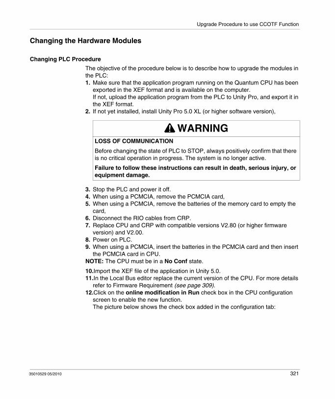
Upgrade Procedure to use CCOTF Function
Changing the Hardware Modules
Changing PLC Procedure
The objective of the procedure below is to describe how to upgrade the modules in the PLC:1. Make sure that the application program running on the Quantum CPU has been
exported in the XEF format and is available on the computer.If not, upload the application program from the PLC to Unity Pro, and export it in the XEF format.
2. If not yet installed, install Unity Pro 5.0 XL (or higher software version),
3. Stop the PLC and power it off. 4. When using a PCMCIA, remove the PCMCIA card,5. When using a PCMCIA, remove the batteries of the memory card to empty the
card,6. Disconnect the RIO cables from CRP.7. Replace CPU and CRP with compatible versions V2.80 (or higher firmware
version) and V2.00.8. Power on PLC.9. When using a PCMCIA, insert the batteries in the PCMCIA card and then insert
the PCMCIA card in CPU.NOTE: The CPU must be in a No Conf state.
10.Import the XEF file of the application in Unity 5.0.11.In the Local Bus editor replace the current version of the CPU. For more details
refer to Firmware Requirement (see page 309).12.Click on the online modification in Run check box in the CPU configuration
screen to enable the new function.The picture below shows the check box added in the configuration tab:
WARNINGLOSS OF COMMUNICATION
Before changing the state of PLC to STOP, always positively confirm that there is no critical operation in progress. The system is no longer active.
Failure to follow these instructions can result in death, serious injury, or equipment damage.
35010529 05/2010 321

Upgrade Procedure to use CCOTF Function
13.Rebuild the application using Rebuild all and download it onto CPU. The CPU is in STOP mode.
14.Reconnect the RIO cable from CRP.
15.Connect Unity Pro to PLC and put the PLC in RUN mode.
WARNINGLOSS OF DATA
At the end of the application download, all the application data in the PLC have their initial values. Before changing the state of the PLC to RUN, always confirm that the application can restart with initial values.
Failure to follow these instructions can result in death, serious injury, or equipment damage.
322 35010529 05/2010

Upgrade Procedure to use CCOTF Function
Changing the CRA Modules in the Quantum RIO Drops
Changing CRA modules in the RIO drops must only be done after the local rack of the PLC have been updated with new CPU and CRP modules:1. Make sure that a powered off RIO drop is supported by the application.2. Power off the RIO drop to update.3. Disconnect the RIO cable from the CRA module, then remove the CRA module
from the drop4. Insert the new CRA module.5. Reconnect the RIO cable on the CRA module.6. Power on the RIO drop.7. Repeat steps 2 through 6 for all RIO drops.
NOTE: All RIO drops configured in the RIO bus must be CCOTF compatible. This means that the corresponding bit in the system word %SW98 and %SW99 must be set to 1. If not, no CCOTF modification is allowed.
NOTE: 800 Series I/O and Sy/Max I/O are not CCOTF compatible. When the CCOTF function is configured, neither 800 Series I/O nor Sy/Max I/O must be connected to the RIO bus.
35010529 05/2010 323
Upgrade Procedure to use CCOTF Function
Upgrading the Firmware
CPU Firmware Upgrade
The CPU firmware download can be done through Modbus or Modbus Plus by using the Unity Pro OS Loader tool.
The following procedure describes the main steps to perform a CPU upgrade:1. Open the OS Loader tool,2. Select the Modbus or Modbus Plus communication option,3. Connect to the CPU using Modbus or Modbus Plus,4. Open the binary file:
Example: 140CPU65160_Vxxx.bin, xxx equal or higher to 280,5. Download the binary file to the CPU.
CRP Firmware Upgrade
The CRP firmware download can be done by using Unity Pro OS Loader tool.
The following procedure describes the main steps to perform a CRP upgrade:1. Open the OS Loader tool,2. Select the Modbus or Modbus Plus communication option,3. Select the Local Head and indicate the Slot Number,4. Select the Download OS to Device option,5. Open the binary file: QCRP932_Vxxx.bin, xxx equal or higher to 200,6. Download the binary file to the CRP.
CRA Firmware Upgrade
The CRA firmware download can be done by using Unity Pro OS Loader tool.
The following procedure describes the main steps to perform a CRA upgrade:1. Open The OS Loader tool,2. Select the Modbus or Modbus Plus communication option,3. Select the Remote I/O Drop and indicate the Drop Number (rotary switch),4. Select the Download OS to Device option,5. Open the binary file: QCRA932_Vxxx.bin, xxx equal or higher to 200,6. Download the binary file to the CRA.
324 35010529 05/2010
35010529 05/2010
33
Using CCOTF
35010529 05/2010
Using CCOTF
Subject of this Chapter
This chapter describes how to add / delete and modify modules in a Quantum configuration that has been upgraded to the CCOTF compatible version.
NOTE: This chapter doesn't apply to Hot Standby systems. For more details using CCOTF function on Hot Standby systems (see Modicon Quantum, Hot Standby with Unity, User Manual)
What's in this Chapter?
This chapter contains the following topics:
Topic Page
General 326
Add / Delete a Module in the Quantum Local Racks 332
Add / Delete a Module in the Quantum RIO Drop 336
Modify Module Parameters 340
325

Using CCOTF
General
Quantum System Configuration Overview
A Quantum configuration can be made of a local rack and Remote I/O drops. The local rack and each remote I/O drop can be made of two backplanes:
The Primary backplane contains the CPU or the Remote I/O drop adapter,The Secondary backplane is linked to the Primary backplane with two backplane expanders.
The picture below shows the elements that can be part of a Quantum configuration:
1. Power Supplies2. CPU or RIO Adapter3. First backplane Expander (140 XBE 100 00)4. Second backplane Expander (140 XBE 100 00)5. Backplane expander Cable (140 XCA 717 0•)6. Cable end marked as “Primary”
326 35010529 05/2010
Using CCOTF
General Advice
There are recommendations to take into account before adding / removing a module from the local racks or RIO drop:
Adding a module in the Unity Pro configuration:Configure the module in Unity Pro,Plug the module in the hardware configuration,Write the sequences of application program to manage the new module.
Removing a module from the configuration:Remove the sequence of application program that is related to the removed module,Unplug the module from the hardware configuration,Remove the module from the unity Pro configuration.
NOTE: It is recommended to add first the module in the Unity Pro configuration screen before adding the module in the PLC. The status bit of the module is set to 0 during the time where the module is configured but not present (Refer to Description of Quantum System Words %SW180 to %SW640 (see Unity Pro, Program Languages and Structure, Reference Manual )). This impacts the defect bits like %S118 or %S119 and %S10. This effect must be taken into account in the application program.
On the other hand, when a parameter is changed, the module is re-started and status bit is set to 0 during several ms. This impacts also the defect bits like %S118 or %S119 and %S10.
WARNINGRISK OF UNEXPECTED EQUIPMENT BEHAVIOUR
Before doing any CCOTF modification, ensure that your system responds appropriately.
Modifications made when the on line modification in RUN check box is selected can have an immediate impact on the process.
Failure to follow these instructions can result in death, serious injury, or equipment damage.
35010529 05/2010 327
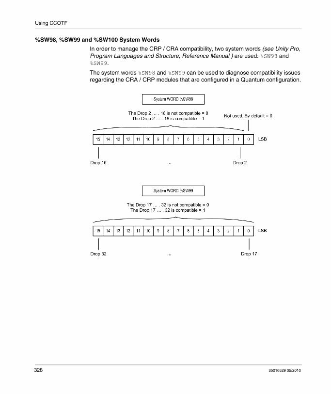
Using CCOTF
%SW98, %SW99 and %SW100 System Words
In order to manage the CRP / CRA compatibility, two system words (see Unity Pro, Program Languages and Structure, Reference Manual ) are used: %SW98 and %SW99.
The system words %SW98 and %SW99 can be used to diagnose compatibility issues regarding the CRA / CRP modules that are configured in a Quantum configuration.
328 35010529 05/2010

Using CCOTF
The following illustrations identify the operating options provided by the Status Register for the two system words %SW98 and %SW99:
NOTE: All RIO drops configured in the RIO bus must be CCOTF compatible. This means that the corresponding bit in the system word %SW98 and %SW99 must be at 1. If this condition is not met and corresponding drop is healthy (CRA health bit is set), no CCOTF modification is allowed.
The system word %SW100 is incremented each time a CCOTF modification is performed in a PLC.
%SW100 = XXYY, where:XX is incremented each time an CCOTF modification is done in RUN state in an RIO drop,YY is incremented each time an CCOTF modification is done in RUN state in the local rack.
NOTE: 800 Series I/O and Sy/Max I/O are not CCOTF compatible. When the CCOTF function is configured, neither 800 Series I/O nor Sy/Max I/O must be connected to the RIO bus.
35010529 05/2010 329
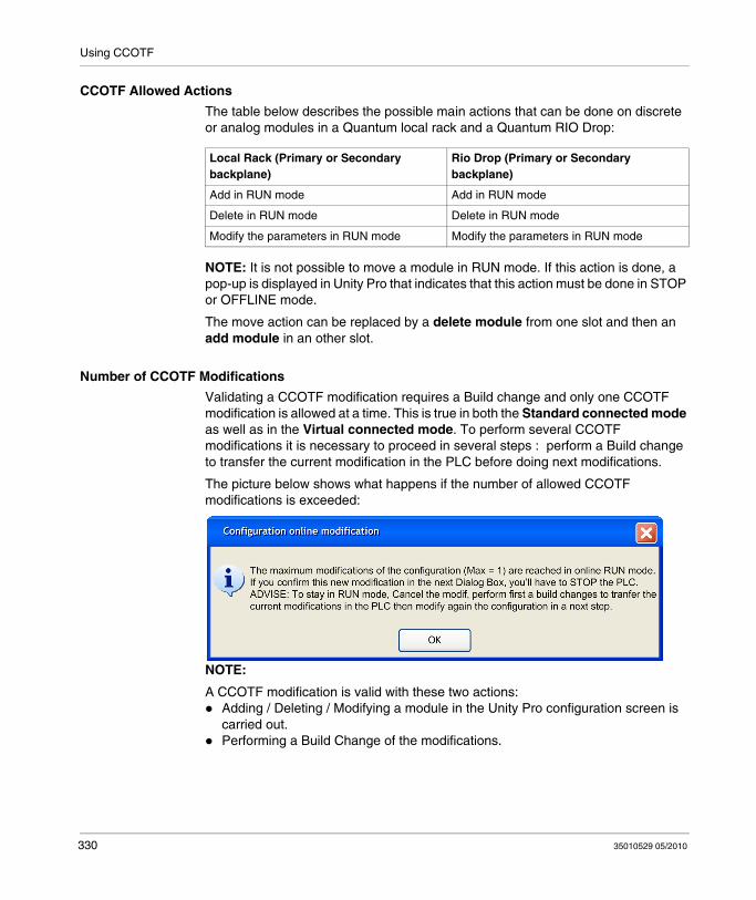
Using CCOTF
CCOTF Allowed Actions
The table below describes the possible main actions that can be done on discrete or analog modules in a Quantum local rack and a Quantum RIO Drop:
NOTE: It is not possible to move a module in RUN mode. If this action is done, a pop-up is displayed in Unity Pro that indicates that this action must be done in STOP or OFFLINE mode.
The move action can be replaced by a delete module from one slot and then an add module in an other slot.
Number of CCOTF Modifications
Validating a CCOTF modification requires a Build change and only one CCOTF modification is allowed at a time. This is true in both the Standard connected mode as well as in the Virtual connected mode. To perform several CCOTF modifications it is necessary to proceed in several steps : perform a Build change to transfer the current modification in the PLC before doing next modifications.
The picture below shows what happens if the number of allowed CCOTF modifications is exceeded:
NOTE:
A CCOTF modification is valid with these two actions:Adding / Deleting / Modifying a module in the Unity Pro configuration screen is carried out.Performing a Build Change of the modifications.
Local Rack (Primary or Secondary backplane)
Rio Drop (Primary or Secondary backplane)
Add in RUN mode Add in RUN mode
Delete in RUN mode Delete in RUN mode
Modify the parameters in RUN mode Modify the parameters in RUN mode
330 35010529 05/2010

Using CCOTF
Example of CCOTF Modification
Recommended CCOTF modification:Insert a new module in a free slot of the Unity Pro configuration screen,Modify the parameters of this module,Validate the parameters modification.
These 3 actions are considered as one CCOTF modification and require one build change.
NOTE: Program modifications (add a new sequence of code, suppress a sequence of code, modify a sequence of code) are not considered part of the CCOTF modification. Only I/O configuration modifications (if they are allowed) are counted.
35010529 05/2010 331

Using CCOTF
Add / Delete a Module in the Quantum Local Racks
Nominal Use Case in Standard Connected Mode
WARNINGPOSSIBLE UNEXPECTED EQUIPMENT BEHAVIOR
Remove the field wiring terminal strip on the module before adding or deleting a module.
Failure to follow these instructions can result in death, serious injury, or equipment damage.
332 35010529 05/2010

Using CCOTF
The following flow-chart describes the action to be done when adding a module to the PLC
35010529 05/2010 333

Using CCOTF
The following flow-chart describes the action to be done when deleting a module from the PLC
Nominal Use Case in Virtual Connected Mode
In this mode, it is possible to modify the I/O configuration when the application is offline. The application that is downloaded onto the PLCs has to be generated with the Virtual connected mode checkbox enabled in the Project settings → General → Build settings.
In OFFLINE mode:
WARNINGPOSSIBLE UNEXPECTED EQUIPMENT BEHAVIOR
Remove the field wiring terminal strip on the module before adding or deleting a module.
Failure to follow these instructions can result in death, serious injury, or equipment damage.
334 35010529 05/2010

Using CCOTF
The following flow-chart describes the action to be done in case of Add or Delete a module:
When connected to the Quantum system:
The following flow-chart describes the action to be done when connected to the Quantum system:
35010529 05/2010 335

Using CCOTF
Add / Delete a Module in the Quantum RIO Drop
Nominal Use Case in Standard Connected Mode
WARNINGPOSSIBLE UNEXPECTED EQUIPMENT BEHAVIOR
Remove the field wiring terminal strip on the module before adding or deleting a module.
Failure to follow these instructions can result in death, serious injury, or equipment damage.
336 35010529 05/2010

Using CCOTF
The following flow-chart describes the action to be done when adding a module to the PLC:
35010529 05/2010 337

Using CCOTF
The following flow-chart describes the action to be done when deleting a module from the PLC:
Nominal Use Case in Virtual Connected Mode
It is possible to modify the I/O configuration when the application is offline. The application that is downloaded in the PLCs has to be generated with the Virtual connected mode check box enabled in the Project settings dialog box.
In OFFLINE mode:
WARNINGPOSSIBLE UNEXPECTED EQUIPMENT BEHAVIOR
Remove the field wiring terminal strip on the module before adding or deleting a module.
Failure to follow these instructions can result in death, serious injury, or equipment damage.
338 35010529 05/2010

Using CCOTF
The following flow-chart describes the action to be done when connected to the Quantum system:
When connected to the Quantum system:
The following flow-chart describes the action to be done when connected to the Quantum system:
35010529 05/2010 339

Using CCOTF
Modify Module Parameters
General
There are two kinds of parameters to take into account:Configuration parameters which are linked with the application memory mapping or the CPU operating system.Examples: Input / Output starting address.Command or adjust parameters which impacts the module behavior.Examples: data format, fallback value, etc. (see Unity Pro, Program Languages and Structure, Reference Manual )
NOTE: In a pre-existing module only the command and adjust parameters can be modified.
NOTE: When a new module is inserting for the first time, all parameters can be modified.
The following picture shows the configuration parameters screen
340 35010529 05/2010

Using CCOTF
Nominal Use Case in Standard Connected Mode
The following flow-chart describes the action to be done:
Nominal Use Case in Virtual Connected Mode
It is possible to modify the I/O configuration and the application offline. The application that is downloaded in the PLCs has to be generated with the Virtual connected mode check box enabled in the Project settings dialog box.
In OFFLINE mode:
WARNINGRISK OF UNEXPECTED EQUIPMENT BEHAVIOUR
Before doing any CCOTF modification, ensure that your system responds appropriately.
Modifications made when the on line modification in RUN check box is selected can have an immediate impact on the process.
Failure to follow these instructions can result in death, serious injury, or equipment damage.
35010529 05/2010 341

Using CCOTF
When connected to the Quantum system:
The following flow-chart describes the action to be done when connected to the Quantum system:
342 35010529 05/2010

35010529 05/2010
34
CCOTF Performance
35010529 05/2010
CCOTF Performance
Key Performance
Cycle Time Impact
The table below describes the cycle time impact depending on the modification done:
NOTE: The percentage varies depending on the cycle time. For time cycle lower than 80 ms, the max time impact could be higher.
Modification Max Time impact
Inserting a new module 30% of the Mast Task cycle time
Deleting a module 30% of the Mast Task cycle time
Modifying parameters of an existing module 30% of the Mast Task cycle time
343
CCOTF Performance
Time to Complete a CCOTF Modification
To understand how a CCOTF modification is performed, the following points have to be considered:
A CCOTF modification is managed at the Mast task frequency.When a CCOTF modification is done in a RIO drop, several specific requests are sent to the CPU in order to modify the CPU memory area containing the I/O drop configuration. This modification is performed when the build change button is clicked in Unity Pro.Memory areas containing all the I/O drop configurations are contiguous in the CPU memory, if the CCOTF modification is related to the first RIO drop, all the other memory areas related to the other RIO drops have to be shifted in the CPU memory. If the CCOTF modification is related to the last RIO drop, only the area of this drop is modified.An important consequence of this point is:
A CCOTF modification in the last RIO drop will require less Mast task cycles than a CCOTF modification in the first RIO drop
Inserting a new module is completed when the status bit of this module is set to 1.
NOTE: The worst case possible is to add a new module in the first RIO drop. The time needed by the system to complete a CCOTF modification is lower than 4 seconds.
344 35010529 05/2010
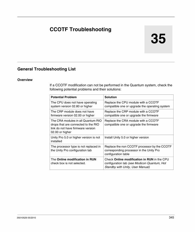
35010529 05/2010
35
Troubleshooting
35010529 05/2010
CCOTF Troubleshooting
General Troubleshooting List
Overview
If a CCOTF modification can not be performed in the Quantum system, check the following potential problems and their solutions:
Potential Problem Solution
The CPU does not have operating system version 02.80 or higher
Replace the CPU module with a CCOTF compatible one or upgrade the operating system
The CRP module does not have firmware version 02.00 or higher
Replace the CRP module with a CCOTF compatible one or upgrade the firmware
The CRA modules in all Quantum RIO drops that are connected to the RIO link do not have firmware version 02.00 or higher
Replace the CRA module with a CCOTF compatible one or upgrade the firmware
Unity Pro 5.0 or higher version is not installed
Install Unity 5.0 or higher version
The processor type is not replaced in the Unity Pro configuration tab
Replace the non CCOTF processor by the CCOTF corresponding processor in the Unity Pro configuration table
The Online modification in RUN check box is not selected.
Check Online modification in RUN in the CPU configuration tab (see Modicon Quantum, Hot Standby with Unity, User Manual)
345

Troubleshooting
NOTE: A Quantum RIO drop which does not contain any I/O module has its corresponding bit at 0 in %SW98 or %SW99. In consequence, an empty Quantum RIO drop blocks CCOTF modifications.
PLC has an application that is not CCOTF compatible
The application must be "rebuilt all" (after changing the processor and checking the Online Modification in RUN check box) and downloaded in PLC
At least one Quantum RIO drop is not compatible with the CCOTF function
Check that all Quantum RIO drops that are configured in the application have their corresponding bits at 1 in %SW98 and %SW99 (excepted those that are not powered on)
A Quantum RIO drop that has been upgraded has its corresponding bit at 0 in %SW98 or %SW99
Power off then power on the RIO drop
Potential Problem Solution
346 35010529 05/2010

35010529 05/2010
Appendices
Introduction
This appendices provide additional information on the Quantum Automation System.
What's in this Appendix?
The appendix contains the following chapters:
Chapter Chapter Name Page
A Miscellaneous Components 349
B Power and Grounding Guidelines 361
C Field Wiring Terminal Strip / Module Keying Assignment 387
D CableFast Cabling 393
E ConneXium Ethernet Cabling System 443
F Agency Approvals and Conformal Coating 449
G System Specifications 461
35010529 05/2010 347

348 35010529 05/2010

35010529 05/2010
A
Miscellaneous Components
35010529 05/2010
Miscellaneous Components
Introduction
This appendix provides information on the various miscellaneous components of the Quantum system, with illustrations and descriptions.
What's in this Chapter?
This chapter contains the following topics:
Topic Page
Racks and Brackets Tables 350
Cables 351
Spare Parts Table 352
Illustrated Miscellaneous Components 353
349
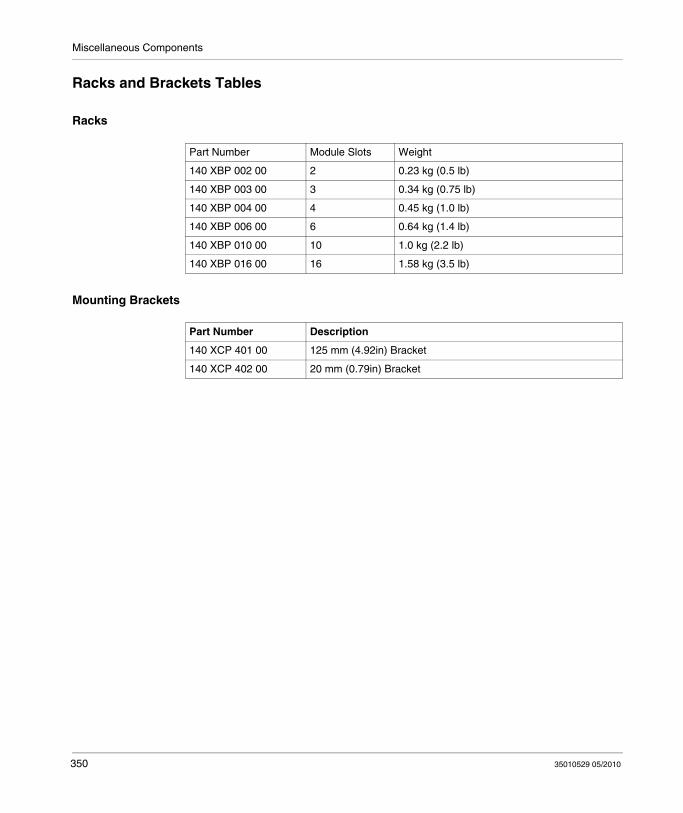
Miscellaneous Components
Racks and Brackets Tables
Racks
Mounting Brackets
Part Number Module Slots Weight
140 XBP 002 00 2 0.23 kg (0.5 lb)
140 XBP 003 00 3 0.34 kg (0.75 lb)
140 XBP 004 00 4 0.45 kg (1.0 lb)
140 XBP 006 00 6 0.64 kg (1.4 lb)
140 XBP 010 00 10 1.0 kg (2.2 lb)
140 XBP 016 00 16 1.58 kg (3.5 lb)
Part Number Description
140 XCP 401 00 125 mm (4.92in) Bracket
140 XCP 402 00 20 mm (0.79in) Bracket
350 35010529 05/2010
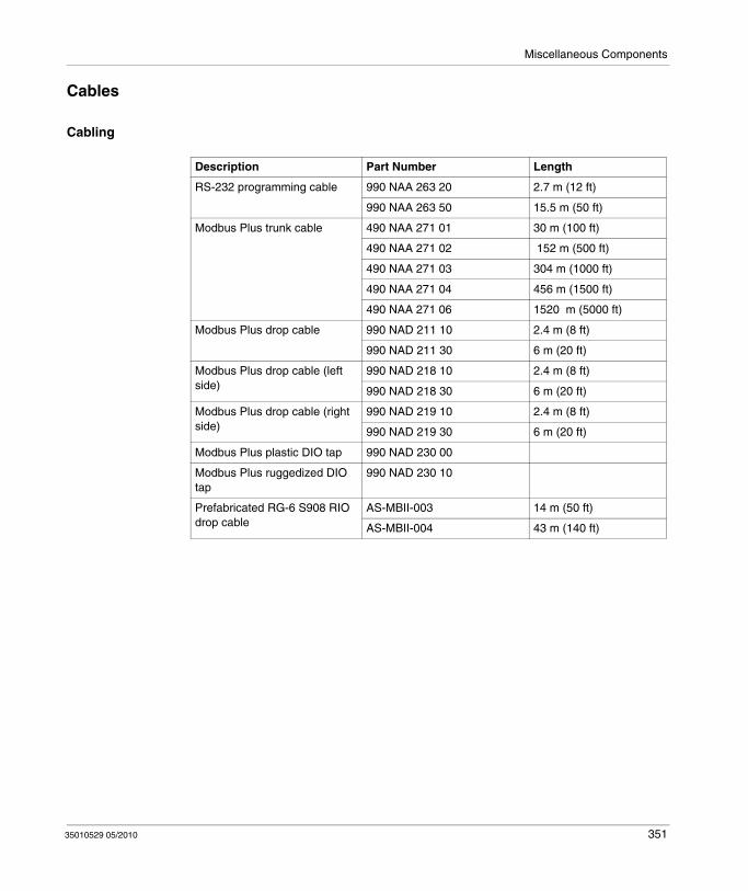
Miscellaneous Components
Cables
Cabling
Description Part Number Length
RS-232 programming cable 990 NAA 263 20 2.7 m (12 ft)
990 NAA 263 50 15.5 m (50 ft)
Modbus Plus trunk cable 490 NAA 271 01 30 m (100 ft)
490 NAA 271 02 152 m (500 ft)
490 NAA 271 03 304 m (1000 ft)
490 NAA 271 04 456 m (1500 ft)
490 NAA 271 06 1520 m (5000 ft)
Modbus Plus drop cable 990 NAD 211 10 2.4 m (8 ft)
990 NAD 211 30 6 m (20 ft)
Modbus Plus drop cable (left side)
990 NAD 218 10 2.4 m (8 ft)
990 NAD 218 30 6 m (20 ft)
Modbus Plus drop cable (right side)
990 NAD 219 10 2.4 m (8 ft)
990 NAD 219 30 6 m (20 ft)
Modbus Plus plastic DIO tap 990 NAD 230 00
Modbus Plus ruggedized DIO tap
990 NAD 230 10
Prefabricated RG-6 S908 RIO drop cable
AS-MBII-003 14 m (50 ft)
AS-MBII-004 43 m (140 ft)
35010529 05/2010 351
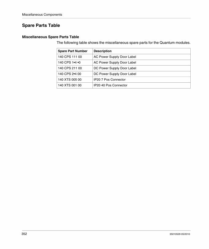
Miscellaneous Components
Spare Parts Table
Miscellaneous Spare Parts Table
The following table shows the miscellaneous spare parts for the Quantum modules.
Spare Part Number Description
140 CPS 111 00 AC Power Supply Door Label
140 CPS 1•4 •0 AC Power Supply Door Label
140 CPS 211 00 DC Power Supply Door Label
140 CPS 2•4 00 DC Power Supply Door Label
140 XTS 005 00 IP20 7 Pos Connector
140 XTS 001 00 IP20 40 Pos Connector
352 35010529 05/2010
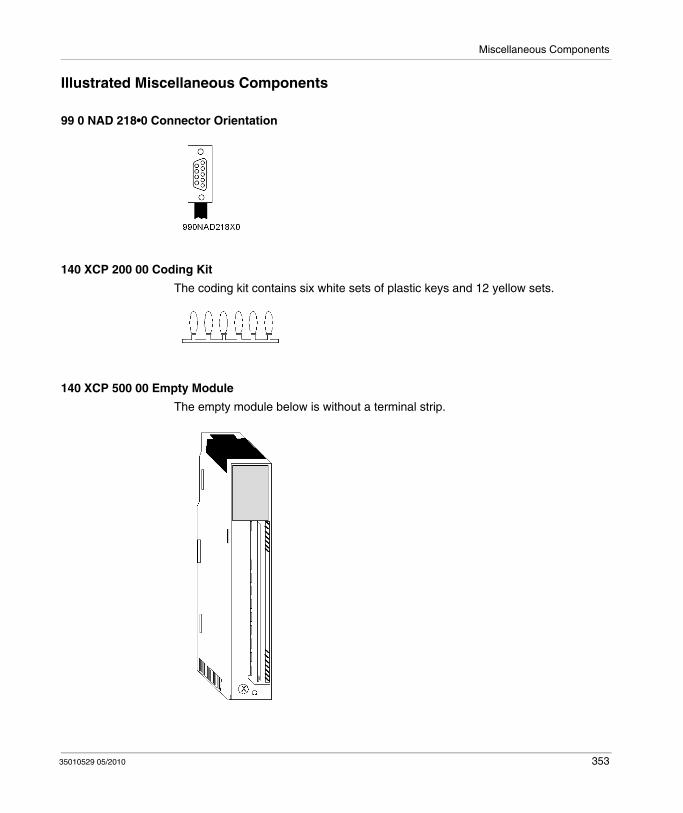
Miscellaneous Components
Illustrated Miscellaneous Components
99 0 NAD 218•0 Connector Orientation
140 XCP 200 00 Coding Kit
The coding kit contains six white sets of plastic keys and 12 yellow sets.
140 XCP 500 00 Empty Module
The empty module below is without a terminal strip.
35010529 05/2010 353

Miscellaneous Components
140 XCP 510 00 Empty Module
The empty module below is without the terminal strip and with a door cover.
140 XCP 600 00 Terminal Strip Jumper Kit
The terminal strip jumper kit contains 12 jumpers.
140 XTS 001 00 40-pin Field Wiring Terminal Strip
The 40-pin field wiring terminal strip has a screw-down bolted cover.
354 35010529 05/2010
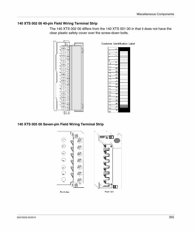
Miscellaneous Components
140 XTS 002 00 40-pin Field Wiring Terminal Strip
The 140 XTS 002 00 differs from the 140 XTS 001 00 in that it does not have the clear plastic safety cover over the screw-down bolts.
140 XTS 005 00 Seven-pin Field Wiring Terminal Strip
35010529 05/2010 355

Miscellaneous Components
990 XCP 900 00 Battery
990 XCP 980 00 CPU Battery
990 NAD 230 00 Modbus Plus Tap
356 35010529 05/2010
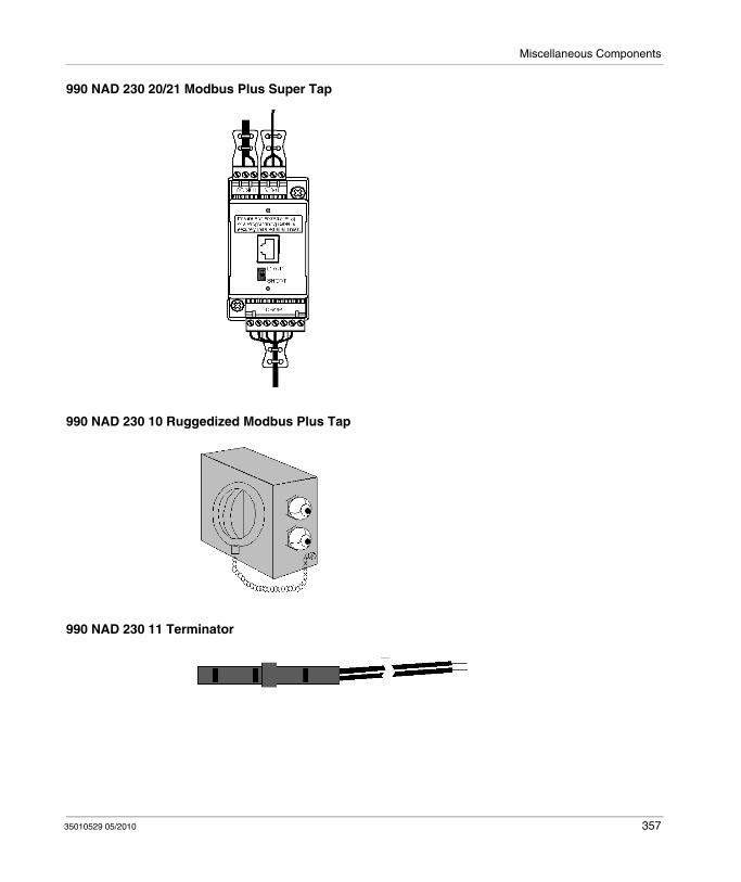
Miscellaneous Components
990 NAD 230 20/21 Modbus Plus Super Tap
990 NAD 230 10 Ruggedized Modbus Plus Tap
990 NAD 230 11 Terminator
35010529 05/2010 357

Miscellaneous Components
990 NAA 215 10 Programming Cable
990 XTS 003 00 200 Series I/O Conversion Connector
MA-0185-100 Remote I/O Tap
358 35010529 05/2010
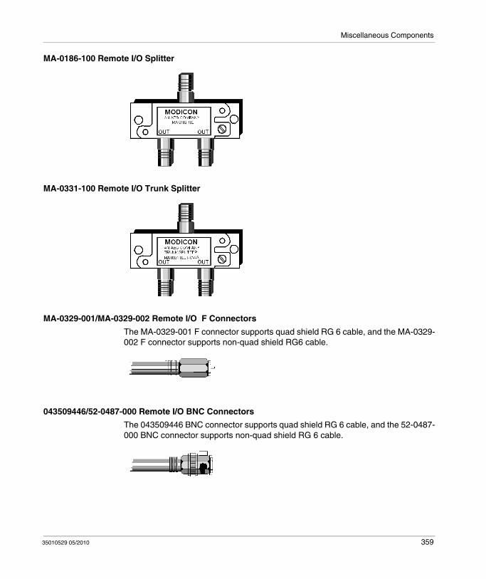
Miscellaneous Components
MA-0186-100 Remote I/O Splitter
MA-0331-100 Remote I/O Trunk Splitter
MA-0329-001/MA-0329-002 Remote I/O F Connectors
The MA-0329-001 F connector supports quad shield RG 6 cable, and the MA-0329-002 F connector supports non-quad shield RG6 cable.
043509446/52-0487-000 Remote I/O BNC Connectors
The 043509446 BNC connector supports quad shield RG 6 cable, and the 52-0487-000 BNC connector supports non-quad shield RG 6 cable.
35010529 05/2010 359

Miscellaneous Components
360 35010529 05/2010

35010529 05/2010
B
Power and Grounding Guidelines
35010529 05/2010
Power and Grounding Guidelines
Introduction
This appendix provides information of power and grounding considerations for AC and DC powered systems, grounding and closed system installation.
What's in this Chapter?
This chapter contains the following topics:
Topic Page
General Information 362
Batteries as DC power supplies 364
AC Power and Grounding Considerations 365
DC Power and Grounding Considerations 369
Closed System Installation 373
Modbus Plus Termination and Grounding 375
Fiber Repeaters 378
Grounding of RIO Networks 380
Analog Grounding Consideration 382
361

Power and Grounding Guidelines
General Information
Overview
The required power and grounding configurations for AC powered and DC powered systems are shown in the following illustrations. Also shown are power and grounding configurations of AC and DC systems required for CE* compliance.
NOTE: Each rack shown has its own ground connection; that is, a separate wire returning to the main grounding point, rather than "daisy chaining" the grounds between power supplies or mounting plates.
The main grounding point is the local common connection of the panel ground, equipment ground, and earth grounding electrode.
CE Compliance
The CE mark indicates compliance with the European Directive on Electromagnetic Compatibility (EMC) (89/336/EEC) and the Low Voltage Directive (73/23/EEC).
NOTE: In order to maintain CE compliance, the Quantum system must be installed in accordance to these instructions.
Chassis Grounding
A chassis ground wire is required for each rack. The wire is connected between one of four ground screws (located on the rack) and the main ground point of the power system. This wire should be green (or green with a yellow stripe) and the AWG rating must be (at a minimum) sized to meet the fuse rating of the supply circuit.
DANGERELECTRIC SHOCK
The user is responsible for compliance with national and local electrical code requirements with respect to grounding of all equipment. Read, understand and implement the wiring and grounding requirements in this section.
Failure to follow these instructions will result in death or serious injury.
362 35010529 05/2010
Power and Grounding Guidelines
Power Supply Grounding
On each power supply connector there is a ground connection. This connection must be made for safety reasons. The preferred connection is between the power supply connector ground terminal and one of the rack ground screws. This wire should be green (or green with a yellow stripe) and at a minimum the same AWG rating as the power connections to the supply.
In racks with multiple power supplies, each supply should have a ground connection between its input connector and the rack ground screws.
NOTE: It is recommended that the power supply, feeding the I/O modules, is grounded at the main ground point.
Other Equipment Grounding
Other equipment in the installation should not share the grounding conductor of the system. Each piece of equipment should have its own grounding conductor returning to the main grounding point from which the equipment power originates.
Systems with Multiple Power Feeds
In systems with multiple power feeds, the grounding should proceed in the same manner as single feed systems. However, a zero volt potential difference must be maintained between the equipment grounding conductors of the separate systems to prevent current flow on communication cables.
35010529 05/2010 363

Power and Grounding Guidelines
Batteries as DC power supplies
Overview
Power Supplies usually provide the adequate isolation from high and low frequency RF noise because of filtered outputs. Batteries provide only good filtering abilities against low frequency noise.
To protect battery powered networks, additional RFI filters are required such as:CURTIS F2800 RFI filtersTRI-MAG, Inc. FL Series Filters or equivalent
364 35010529 05/2010

Power and Grounding Guidelines
AC Power and Grounding Considerations
AC Powered Systems
NOTE: *AC N should be earth grounded. If it is not earth grounded, it must be fused (refer to local codes).
35010529 05/2010 365
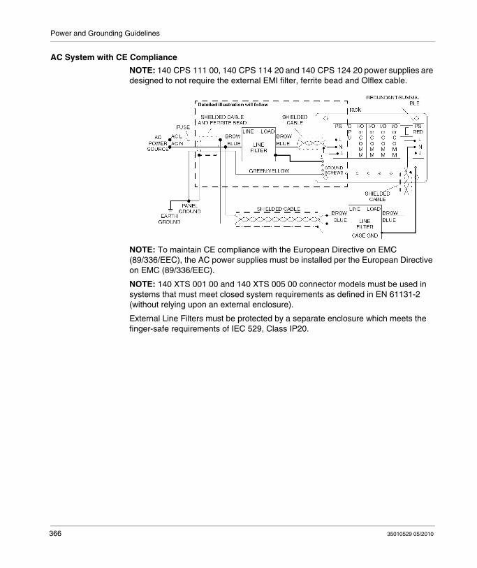
Power and Grounding Guidelines
AC System with CE Compliance
NOTE: 140 CPS 111 00, 140 CPS 114 20 and 140 CPS 124 20 power supplies are designed to not require the external EMI filter, ferrite bead and Olflex cable.
NOTE: To maintain CE compliance with the European Directive on EMC (89/336/EEC), the AC power supplies must be installed per the European Directive on EMC (89/336/EEC).
NOTE: 140 XTS 001 00 and 140 XTS 005 00 connector models must be used in systems that must meet closed system requirements as defined in EN 61131-2 (without relying upon an external enclosure).
External Line Filters must be protected by a separate enclosure which meets the finger-safe requirements of IEC 529, Class IP20.
366 35010529 05/2010
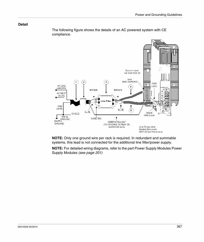
Power and Grounding Guidelines
Detail
The following figure shows the details of an AC powered system with CE compliance.
NOTE: Only one ground wire per rack is required. In redundant and summable systems, this lead is not connected for the additional line filter/power supply.
NOTE: For detailed wiring diagrams, refer to the part Power Supply Modules Power Supply Modules (see page 201)
35010529 05/2010 367

Power and Grounding Guidelines
Part List
Callout Vendor or equivalent
Part Number Description Instruction
1 Oflex-Series 100 cy 35005 Line Cord Terminate the shield at panel ground; the filter end of the shield is not terminated.
2 StewartFairite
28 B 0686-2002643665702
Ferrite Bead Install next to the filter and fasten with tie wraps at both ends of the ferrite bead.
3 Schaffner FN670-3/06 Line Filter (fast on terminals)Dimensions:Length:85 mm (3.4 in)Width: 55 mm (2.2 in)Height: 40 mm (1.6 in)Mounting Holes: 5.3 mm (0.2 in) diameter75 mm (3 in) centerline mounted.Fast on terminals: 6.4 mm (0.25 in)
Install next to the power supply.
4 NA NA Ground BraidFlat braid 134 mm (0.5 in) with a maximum length of 100 mm (4 in)
NA
5 Oflex Series 100cy 35005 Shield CableMaximum length: 215 mm (8.5 in)
Third lead (green/yellow) is not used; terminate the shield at the power supply ground terminal.
368 35010529 05/2010

Power and Grounding Guidelines
DC Power and Grounding Considerations
24 VDC Powered System Figure
The following figure shows a 24 VDC powered system.
NOTE: It is recommended to earth ground the 24 VDC power supply.
24 VDC Powered System for CE Compliance
The following figure shows a 3 A, 24 VDC powered system for CE compliance.
35010529 05/2010 369
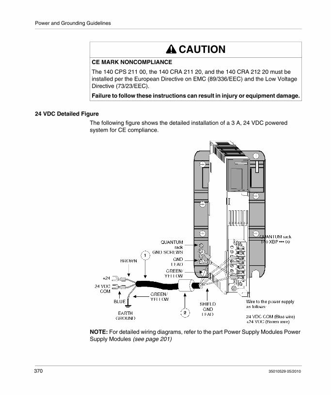
Power and Grounding Guidelines
24 VDC Detailed Figure
The following figure shows the detailed installation of a 3 A, 24 VDC powered system for CE compliance.
NOTE: For detailed wiring diagrams, refer to the part Power Supply Modules Power Supply Modules (see page 201)
CAUTIONCE MARK NONCOMPLIANCE
The 140 CPS 211 00, the 140 CRA 211 20, and the 140 CRA 212 20 must be installed per the European Directive on EMC (89/336/EEC) and the Low Voltage Directive (73/23/EEC).
Failure to follow these instructions can result in injury or equipment damage.
370 35010529 05/2010
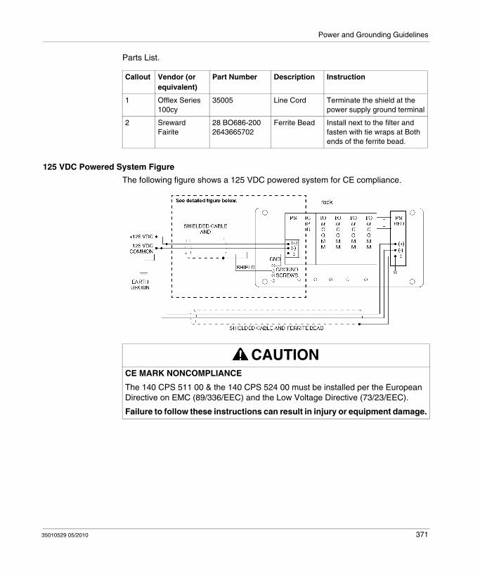
Power and Grounding Guidelines
Parts List.
125 VDC Powered System Figure
The following figure shows a 125 VDC powered system for CE compliance.
Callout Vendor (or equivalent)
Part Number Description Instruction
1 Offlex Series 100cy
35005 Line Cord Terminate the shield at the power supply ground terminal
2 SrewardFairite
28 BO686-2002643665702
Ferrite Bead Install next to the filter and fasten with tie wraps at Both ends of the ferrite bead.
CAUTIONCE MARK NONCOMPLIANCE
The 140 CPS 511 00 & the 140 CPS 524 00 must be installed per the European Directive on EMC (89/336/EEC) and the Low Voltage Directive (73/23/EEC).
Failure to follow these instructions can result in injury or equipment damage.
35010529 05/2010 371

Power and Grounding Guidelines
125 VDC Detailed Figure
The following figure shows the detailed installation for the 125 VDC powered system for CE compliance.
NOTE: For detailed wiring diagrams of power supply modules, refer to the part Part Power Supplies (see page 201)
Parts List.
Callout Vendor (or equivalent)
Part Number Description Instruction
1 Offlex Series 100cy
35005 Line Cord Terminate the shield at the power supply ground terminal
2 SrewardFairite
28 BO686-2002643665702
Ferrite Bead Install next to the filter and secure with tie wraps at Both ends of the ferrite bead.
CAUTIONEUROPEAN COMPLIANCE
The 140 CPS 511 00 & the 140 CPS 524 00 must be installed per the European Directive on EMC (89/336/EEC) and the Low Voltage Directive (73/23/EEC).
Failure to follow these instructions can result in injury or equipment damage.
372 35010529 05/2010

Power and Grounding Guidelines
Closed System Installation
Overview
For installations that must meet closed system requirements as defined in EN 61131-2 (without relying upon an external enclosure) in which an external line filter is used, it must be protected by a separate enclosure that meets the finger-safe requirements of IEC 529, Class IP20.
AC/DC Installation
The following figure shows an AC/DC powered systems that meets CE closed system compliance.
* Only one ground wire per rack is required. In redundant and summable systems, this lead is not connected for the additional line filter/power supply
** Connectors 140 XTS 005 00 (for power supplies) and 140 XTS 001 00 (for I/O modules) must be ordered separately
NOTE: For detailed wiring diagrams, refer to the part Power Supply Modules Power Supply Modules (see page 201)
35010529 05/2010 373

Power and Grounding Guidelines
Protective Cover
The protective cover must completely enclose the line filter. Approximate dimensions for the cover are 12.5 x 7.5 cm. Wire entry/exit shall be through strain relief bushings.
Line Filter Connections
374 35010529 05/2010

Power and Grounding Guidelines
Modbus Plus Termination and Grounding
How Taps Have to Be Terminated
A tap is required at each site on the trunk cable to provide connections for the trunk cable and drop cable. Each tap contains an internal terminating resistor that can be connected by two jumpers. Two jumper wires are included in the tap package, but are not installed. At the taps at the two ends of a cable section, you must connect both of the jumpers to provide the proper terminating impedance for the network. Taps at inline sites must have both jumpers removed. The impedance is maintained regardless of whether a node device is connected to the drop cable. Any connector can be disconnected from its device without affecting the network impedance.
The diagram shows a Modbus Plus Network connection with terminating resistors and grounding.
35010529 05/2010 375

Power and Grounding Guidelines
Grounding at the Tap
Each tap has a grounding screw for connection to the site panel ground. Schneider Electric drop cables have a grounding lug in the cable package. This must betightly crimped or soldered on the cable and connected to the grounding screw on the tap.
The diagram shows a drop cable, connected and grounded with a tap.
The node device end of the drop cable has a lug which must be connected to the node device’s panel ground. The network cable must be grounded through this connection at each node site, even when the node device is not present. The ground point must not be left open. No other grounding method can be used.
376 35010529 05/2010
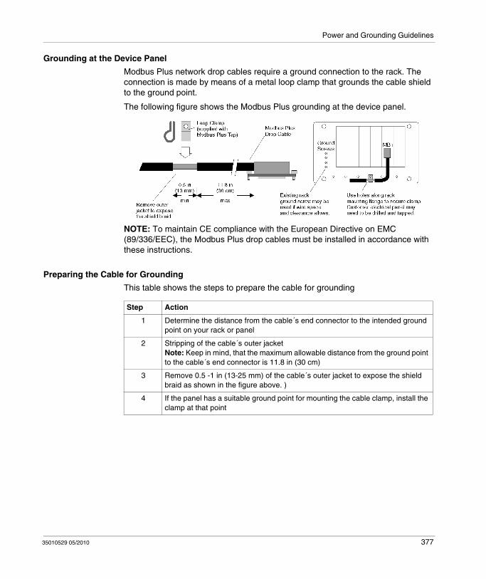
Power and Grounding Guidelines
Grounding at the Device Panel
Modbus Plus network drop cables require a ground connection to the rack. The connection is made by means of a metal loop clamp that grounds the cable shield to the ground point.
The following figure shows the Modbus Plus grounding at the device panel.
NOTE: To maintain CE compliance with the European Directive on EMC (89/336/EEC), the Modbus Plus drop cables must be installed in accordance with these instructions.
Preparing the Cable for Grounding
This table shows the steps to prepare the cable for grounding
Step Action
1 Determine the distance from the cable´s end connector to the intended ground point on your rack or panel
2 Stripping of the cable´s outer jacketNote: Keep in mind, that the maximum allowable distance from the ground point to the cable´s end connector is 11.8 in (30 cm)
3 Remove 0.5 -1 in (13-25 mm) of the cable´s outer jacket to expose the shield braid as shown in the figure above. )
4 If the panel has a suitable ground point for mounting the cable clamp, install the clamp at that point
35010529 05/2010 377

Power and Grounding Guidelines
Fiber Repeaters
Grounding a Modbus Plus Fiber Repeater
Connecting AC Power to the Repeater
Connecting DC Power to the Repeater
Step Action
1 Connect the Repeater to the site groundResult: The Repeater obtains it´s ground through the chassis ground screw or DC (-) wire.
2 Use a continuity tester to verify, that the repeater is grounded to the site ground.
Step Action
1 Remove the power at it´s source.
2 If necessary install a different plug on the cable for the power source at your site.Note: The AC power cable supplied with the repeater is keyed for North American 110-120 VAC outlets.
3 Remove the AC power cable from the repeater
4 Set the power selector plug to the 110-120 VAC or 220-240 VAC position for the power source at your site. To do this:1. Remove the power selector plug by prying under it´s tab using a small screw
driver.2. Set the plug to the proper voltage position as shown on the plug body.3. Reinsert the plug.
5 Insert the AC power cable in the rear panel connector.
6 Insert the AC power cable into the power source.
Step Action
1 Remove the power at it´s source.
2 Connect the source to the DC power terminals, observing the proper polarity.
378 35010529 05/2010
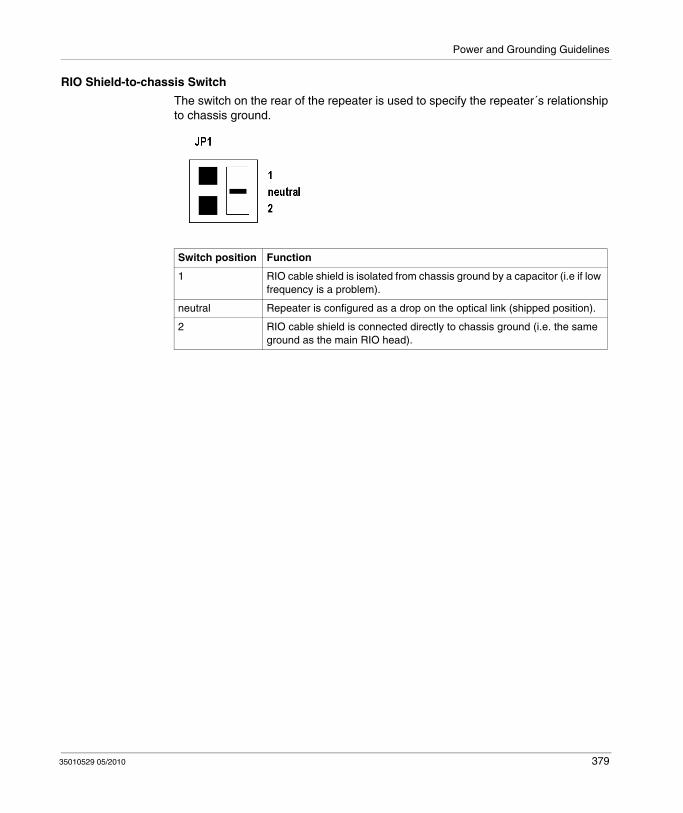
Power and Grounding Guidelines
RIO Shield-to-chassis Switch
The switch on the rear of the repeater is used to specify the repeater´s relationship to chassis ground.
Switch position Function
1 RIO cable shield is isolated from chassis ground by a capacitor (i.e if low frequency is a problem).
neutral Repeater is configured as a drop on the optical link (shipped position).
2 RIO cable shield is connected directly to chassis ground (i.e. the same ground as the main RIO head).
35010529 05/2010 379
Power and Grounding Guidelines
Grounding of RIO Networks
Overview
The Remote I/O communication is based on single point grounding, that is located at the head.Coaxial cable and taps have no additional connection to the ground to help eliminate low frequency ground loops.
Missing grounding
A cable system must be grounded at all times to ensure safety and proper operation of the nodes on the network. The cable system is grounded by the RIO head processor. But if the cable is removed, the ground connection doesn’t work anymore.
Ground Blocks
Ground blocks provide grounding, even if the cable is removed.
Additional properties are as follows:Low insertion lossOnly if five or more are used, they have to be considered in the trunk attenuation with 0.2 dB each. The impedance is 75 Ω and the return loss >40 dB.Wide application frequency
Ground Block structure
The ground block 60-0545-000 consists of two female in-line F connectors and a separate screw hole binding for attaching a ground wire. The grounding block has two mounting holes, allowing it to be mounted to a flat surface. Two styles of the ground block 60-0545-000 are available and may be used interchangeable.
380 35010529 05/2010

Power and Grounding Guidelines
This diagram shows the dimensions of the two available 60-0545-000 grounding blocks.
NOTE: Local building codes may require the cable shield tied to ground, whenever the cable system exits and/or enters a new building (NEC Article 820-33).
Surge protection
Surge protection is available for coaxial network trunks that span between buildings and are exposed to lightning. The recommended product has internal gas discharge surge protectors that absorb very high currents induced into the cable system by near-lightning strikes. The device indicated has insertion loss of less than 0.3 dB at the network operating frequency. The unused drop ports must be terminated with a 52-0402-000 Port Terminator. If desired, shrink tubing may be used to seal the F connections.
The device should be accessible for maintenance, and be protected from the elements if installed outside. The threaded stud should be connected to building ground.
The recommended product is Relcom Inc. p/n CBT-22300G. Contact information is:
Relcom Inc.
2221 Yew Street Forest Grove, Oregon 97116, USA
Tel: (800) 382-3765
www.relcominc.com
35010529 05/2010 381
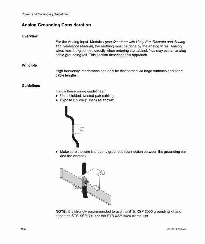
Power and Grounding Guidelines
Analog Grounding Consideration
Overview
For the Analog Input Modules (see Quantum with Unity Pro, Discrete and Analog I/O, Reference Manual), the earthing must be done by the analog wires. Analog wires must be grounded directly when entering the cabinet. You may use an analog cable grounding rail. This section describes this approach.
Principle
High frequency interference can only be discharged via large surfaces and short cable lengths.
Guidelines
Follow these wiring guidelines:Use shielded, twisted-pair cabling.Expose 2.5 cm (1 inch) as shown:.
Make sure the wire is properly grounded (connection between the grounding bar and the clamps).
NOTE: It is strongly recommended to use the STB XSP 3000 grounding kit and, either the STB XSP 3010 or the STB XSP 3020 clamp kits.
2.5 cm1 inch
382 35010529 05/2010
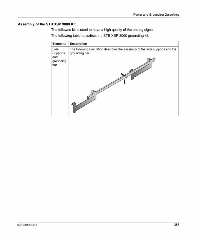
Power and Grounding Guidelines
Assembly of the STB XSP 3000 Kit
The followed kit is used to have a high quality of the analog signal.
The following table describes the STB XSP 3000 grounding kit.
Elements Description
Side Supports and grounding bar
The following illustration describes the assembly of the side supports and the grounding bar.
35010529 05/2010 383
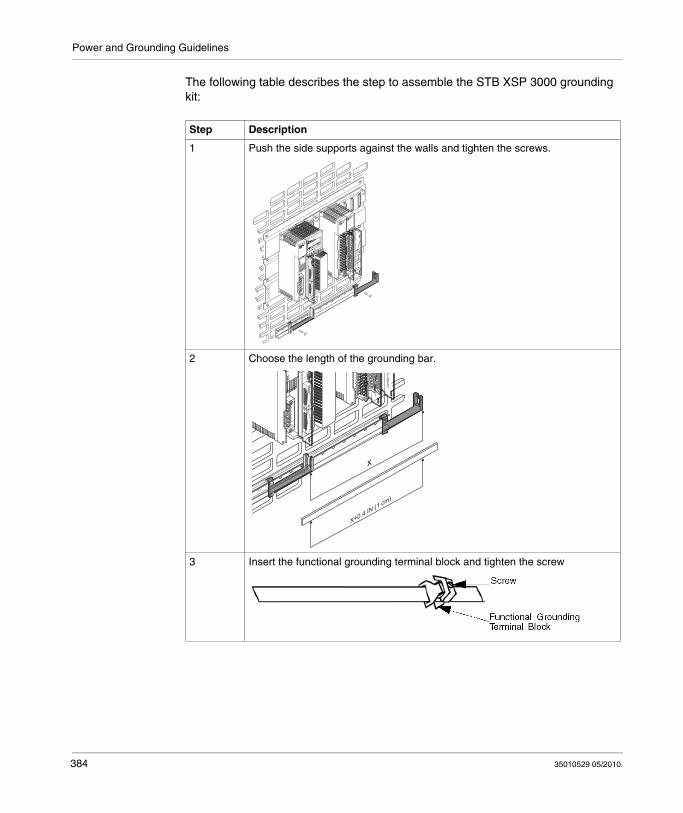
Power and Grounding Guidelines
The following table describes the step to assemble the STB XSP 3000 grounding kit:
Step Description
1 Push the side supports against the walls and tighten the screws.
2 Choose the length of the grounding bar.
3 Insert the functional grounding terminal block and tighten the screw
ESC
MOD
ENTER
SC
X+0.4 IN (1 cm)
384 35010529 05/2010

Power and Grounding Guidelines
4 Fix the grounding bar at the side supports.
5 The following figure describes the final assembly of the STB XSP 3000.
Step Description
ESC
MOD
ENTER
SC
35010529 05/2010 385

Power and Grounding Guidelines
STB XSP 3010 Kit and STB XSP 3020
The following table describes the different cable sections (in AWG and mm2):
Final Assembly
The following figure shows the final assembly:
Reference AWG mm2
STB XSP 3010 16 to 9 1.5 to 6.5
STB XSP 3020 10 to 7 5 to 11
ESC
MOD
ENTER
SC
386 35010529 05/2010

35010529 05/2010
C
Module Keying
35010529 05/2010
Field Wiring Terminal Strip / Module Keying Assignment
Purpose
This appendix provides information on Field Wiring Terminal Strip / Module Keying Assignment of I/O modules
What's in this Chapter?
This chapter contains the following topics:
Topic Page
General Information 388
Illustration 389
Primary Keying 390
Secondary Keying 392
387

Module Keying
General Information
Location
Field wiring terminal strips and module housings are slotted on the left and right sides of the PCB card slot to accept keying pins (see I/O Module Figure, page 389).
Purpose
To prevent plugging the terminal strip into the wrong module, once wiring connections have been made. Keying is implemented at the discretion of the user.
NOTE: Schneider Electric recommends that module key coding be part of the system installation procedure.
Primary Keying
Primary keying is provided on the right side of the module, marked A through F (top and bottom positions are coded the same). Primary keying provides module class coding. Primary codes have been pre-defined, according to the following tables.
Secondary Keying
Secondary keying is provided on the left side of the module, marked 1 through 6. Secondary keying codes are user-definable and may be used to identify module personality within module classes, or other unique site requirements.
The user may also use personality keying to differentiate between like module types (i.e., 140 DAO 840 00 and 140 DAO 842 10 both have the same primary keying pin combinations), using the white keys for each code.
388 35010529 05/2010
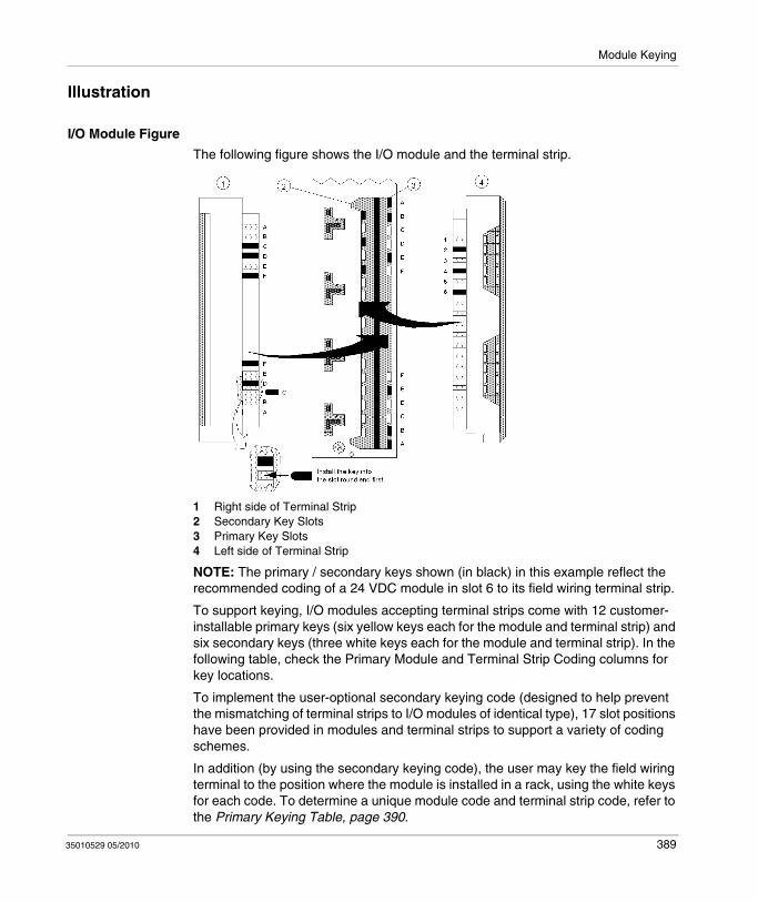
Module Keying
Illustration
I/O Module Figure
The following figure shows the I/O module and the terminal strip.
1 Right side of Terminal Strip 2 Secondary Key Slots3 Primary Key Slots4 Left side of Terminal Strip
NOTE: The primary / secondary keys shown (in black) in this example reflect the recommended coding of a 24 VDC module in slot 6 to its field wiring terminal strip.
To support keying, I/O modules accepting terminal strips come with 12 customer-installable primary keys (six yellow keys each for the module and terminal strip) and six secondary keys (three white keys each for the module and terminal strip). In the following table, check the Primary Module and Terminal Strip Coding columns for key locations.
To implement the user-optional secondary keying code (designed to help prevent the mismatching of terminal strips to I/O modules of identical type), 17 slot positions have been provided in modules and terminal strips to support a variety of coding schemes.
In addition (by using the secondary keying code), the user may key the field wiring terminal to the position where the module is installed in a rack, using the white keys for each code. To determine a unique module code and terminal strip code, refer to the Primary Keying Table, page 390.
35010529 05/2010 389
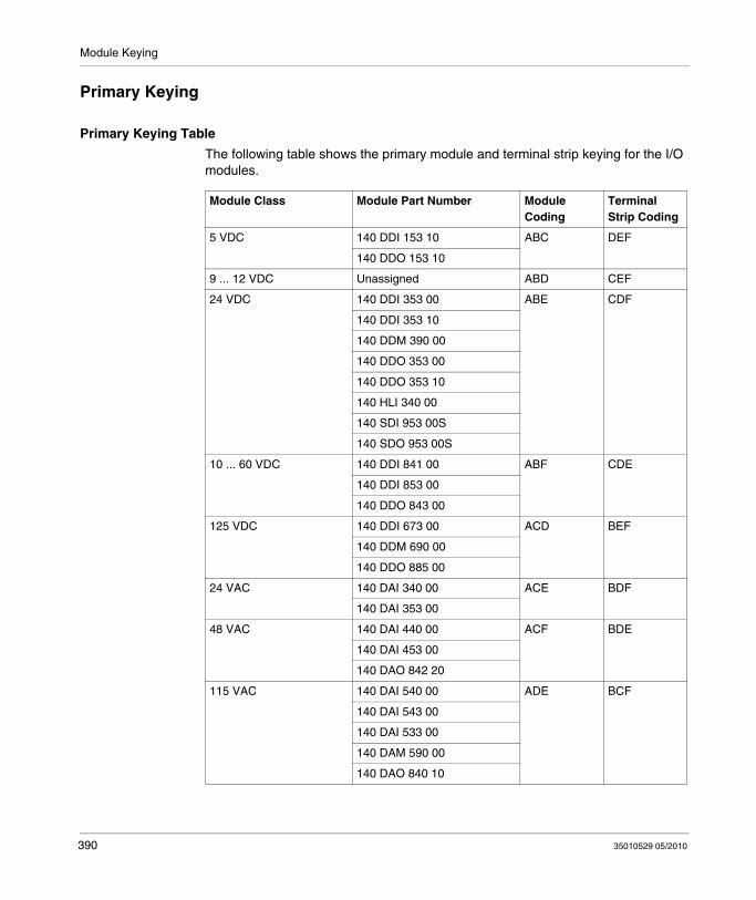
Module Keying
Primary Keying
Primary Keying Table
The following table shows the primary module and terminal strip keying for the I/O modules.
Module Class Module Part Number Module Coding
Terminal Strip Coding
5 VDC 140 DDI 153 10 ABC DEF
140 DDO 153 10
9 ... 12 VDC Unassigned ABD CEF
24 VDC 140 DDI 353 00 ABE CDF
140 DDI 353 10
140 DDM 390 00
140 DDO 353 00
140 DDO 353 10
140 HLI 340 00
140 SDI 953 00S
140 SDO 953 00S
10 ... 60 VDC 140 DDI 841 00 ABF CDE
140 DDI 853 00
140 DDO 843 00
125 VDC 140 DDI 673 00 ACD BEF
140 DDM 690 00
140 DDO 885 00
24 VAC 140 DAI 340 00 ACE BDF
140 DAI 353 00
48 VAC 140 DAI 440 00 ACF BDE
140 DAI 453 00
140 DAO 842 20
115 VAC 140 DAI 540 00 ADE BCF
140 DAI 543 00
140 DAI 533 00
140 DAM 590 00
140 DAO 840 10
390 35010529 05/2010
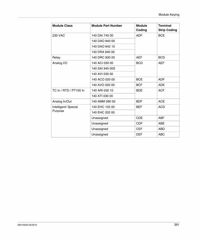
Module Keying
230 VAC 140 DAI 740 00 ADF BCE
140 DAO 840 00
140 DAO 842 10
140 DRA 840 00
Relay 140 DRC 830 00 AEF BCD
Analog I/O 140 ACI 030 00 BCD AEF
140 SAI 940 00S
140 AVI 030 00
140 ACO 020 00 BCE ADF
140 AVO 020 00 BCF ADE
TC In / RTD / PT100 In 140 ARI 030 10 BDE ACF
140 ATI 030 00
Analog In/Out 140 AMM 090 00 BDF ACE
Intelligent/ Special Purpose
140 EHC 105 00 BEF ACD
140 EHC 202 00
Unassigned CDE ABF
Unassigned CDF ABE
Unassigned CEF ABD
Unassigned DEF ABC
Module Class Module Part Number Module Coding
Terminal Strip Coding
35010529 05/2010 391
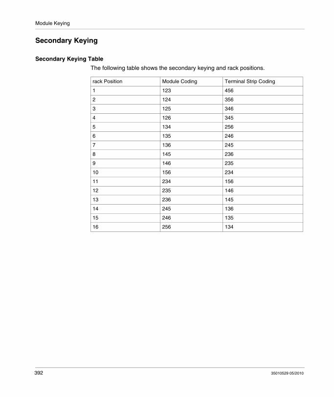
Module Keying
Secondary Keying
Secondary Keying Table
The following table shows the secondary keying and rack positions.
rack Position Module Coding Terminal Strip Coding
1 123 456
2 124 356
3 125 346
4 126 345
5 134 256
6 135 246
7 136 245
8 145 236
9 146 235
10 156 234
11 234 156
12 235 146
13 236 145
14 245 136
15 246 135
16 256 134
392 35010529 05/2010

35010529 05/2010
D
CableFast Cabling
35010529 05/2010
CableFast Cabling
Introduction
This appendix provides information to the CableFast cabling system.
What's in this Chapter?
This chapter contains the following topics:
Topic Page
General Information 394
140 CFA 040 00 Quantum CableFast Cabling Block 401
140 CFB 032 00 Quantum CableFast Cabling Block 403
140 CFC 032 00 Quantum CableFast Cabling Block 406
140 CFD 032 00 Quantum CableFast Cabling Block 412
140 CFE 032 00 Quantum CableFast Cabling Block 414
140 CFG 016 00 Quantum CableFast Cabling Block 416
140 CFH 008 00 Quantum CableFast Cabling Block 421
140CFI00800 Quantum CableFast Cabling Block 425
140CFJ00400 Quantum CableFast Cabling Block 429
140CFK00400 Quantum CableFast Cabling Block 433
CableFast Cables 437
CableFast Accessories 442
393

CableFast Cabling
General Information
Overview
The CableFast wiring system consists of pre-wired Quantum field wiring terminal strips in various cable lengths, terminated with D-type connectors. The D connectors plug into DIN rail-mounted terminal blocks offered in straight-through or special application versions. Cables and terminal blocks are ordered separately. Terminal blocks may be used with any cable length. Pigtail cable versions are also available.
Quantum I/O Modules with CableFast Components
NOTE: Make sure that the wiring conduits are large enough to support 3.65 m (12 ft) cables.
394 35010529 05/2010
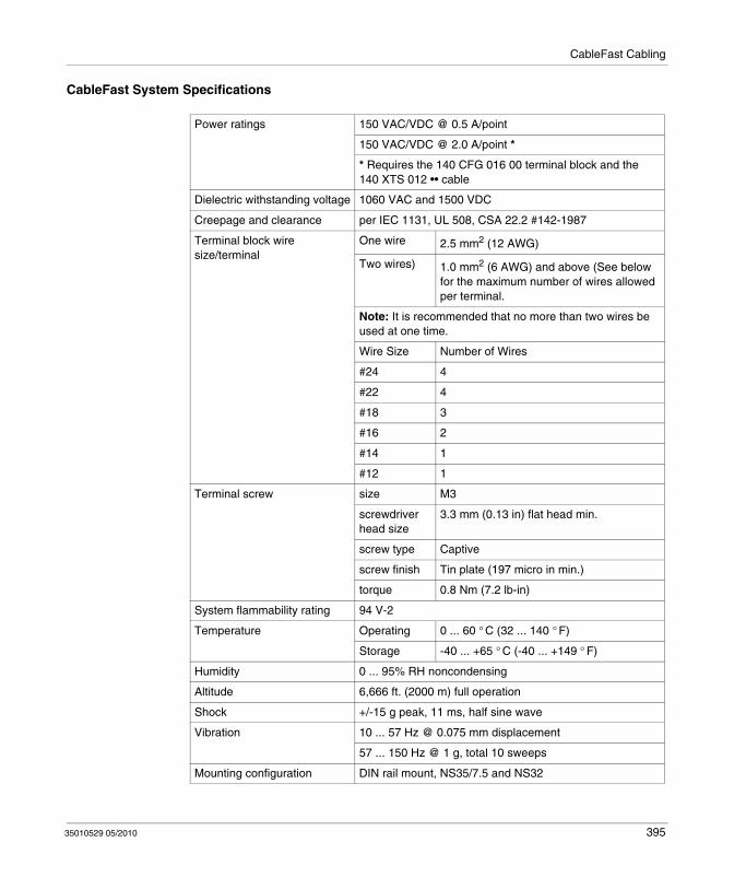
CableFast Cabling
CableFast System Specifications
Power ratings 150 VAC/VDC @ 0.5 A/point
150 VAC/VDC @ 2.0 A/point *
* Requires the 140 CFG 016 00 terminal block and the 140 XTS 012 •• cable
Dielectric withstanding voltage 1060 VAC and 1500 VDC
Creepage and clearance per IEC 1131, UL 508, CSA 22.2 #142-1987
Terminal block wire size/terminal
One wire 2.5 mm2 (12 AWG)
Two wires) 1.0 mm2 (6 AWG) and above (See below for the maximum number of wires allowed per terminal.
Note: It is recommended that no more than two wires be used at one time.
Wire Size Number of Wires
#24 4
#22 4
#18 3
#16 2
#14 1
#12 1
Terminal screw size M3
screwdriver head size
3.3 mm (0.13 in) flat head min.
screw type Captive
screw finish Tin plate (197 micro in min.)
torque 0.8 Nm (7.2 lb-in)
System flammability rating 94 V-2
Temperature Operating 0 ... 60 ° C (32 ... 140 ° F)
Storage -40 ... +65 ° C (-40 ... +149 ° F)
Humidity 0 ... 95% RH noncondensing
Altitude 6,666 ft. (2000 m) full operation
Shock +/-15 g peak, 11 ms, half sine wave
Vibration 10 ... 57 Hz @ 0.075 mm displacement
57 ... 150 Hz @ 1 g, total 10 sweeps
Mounting configuration DIN rail mount, NS35/7.5 and NS32
35010529 05/2010 395

CableFast Cabling
Terminal Block Selection Guide
140 CFA 040 00
140 CFB 032 00
140 CFC 032 00
140 CFD 004 00
140 CFE 032 00
140 CFG 016 00
140 CFH 008 00
140 CFI 008 00
140 CFJ 004 00
140 CFK 004 00
140 ACI 030 00 X X X
140 ACO 020 00 X X X
140 ACI 040 00 X
140 ACO 130 00 X
140 ARI 030 10 X
140 ATI 030 00 X (see note 3)
140 AMM 090 00 X
14 AVI 030 00 X X X
140 AVO 020 00 X X
140 DAI 340 00 X X
140 DAI 353 00 X X X X
140 DAI 440 00 X X
140 DAI 453 00 X X X X
140 DAI 540 00 X X
140 DAI 543 00 X
140 DAI 553 00 X X X X
140 DAI 740 00 CableFast not allowed
140 DAI 753 00
140 DAM 590 00 X see note 1
140 DAO 840 00 – X (see note 2
140 DAO 840 10 X (see note 2
140 DAO 842 10 – X (see note 2
396 35010529 05/2010
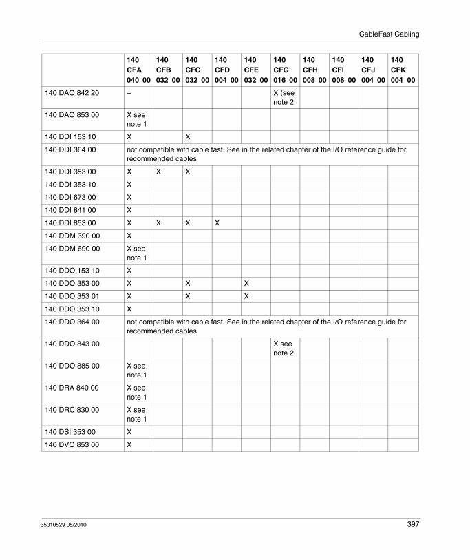
CableFast Cabling
140 DAO 842 20 – X (see note 2
140 DAO 853 00 X see note 1
140 DDI 153 10 X X
140 DDI 364 00 not compatible with cable fast. See in the related chapter of the I/O reference guide for recommended cables
140 DDI 353 00 X X X
140 DDI 353 10 X
140 DDI 673 00 X
140 DDI 841 00 X
140 DDI 853 00 X X X X
140 DDM 390 00 X
140 DDM 690 00 X see note 1
140 DDO 153 10 X
140 DDO 353 00 X X X
140 DDO 353 01 X X X
140 DDO 353 10 X
140 DDO 364 00 not compatible with cable fast. See in the related chapter of the I/O reference guide for recommended cables
140 DDO 843 00 X see note 2
140 DDO 885 00 X see note 1
140 DRA 840 00 X see note 1
140 DRC 830 00 X see note 1
140 DSI 353 00 X
140 DVO 853 00 X
140 CFA 040 00
140 CFB 032 00
140 CFC 032 00
140 CFD 004 00
140 CFE 032 00
140 CFG 016 00
140 CFH 008 00
140 CFI 008 00
140 CFJ 004 00
140 CFK 004 00
35010529 05/2010 397
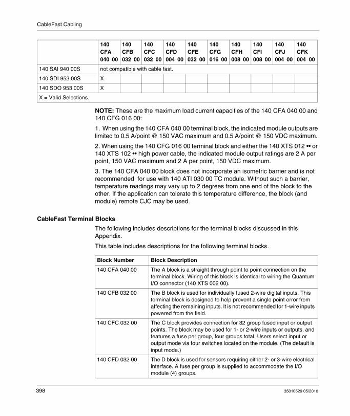
CableFast Cabling
NOTE: These are the maximum load current capacities of the 140 CFA 040 00 and 140 CFG 016 00:
1. When using the 140 CFA 040 00 terminal block, the indicated module outputs are limited to 0.5 A/point @ 150 VAC maximum and 0.5 A/point @ 150 VDC maximum.
2. When using the 140 CFG 016 00 terminal block and either the 140 XTS 012 •• or 140 XTS 102 •• high power cable, the indicated module output ratings are 2 A per point, 150 VAC maximum and 2 A per point, 150 VDC maximum.
3. The 140 CFA 040 00 block does not incorporate an isometric barrier and is not recommended for use with 140 ATI 030 00 TC module. Without such a barrier, temperature readings may vary up to 2 degrees from one end of the block to the other. If the application can tolerate this temperature difference, the block (and module) remote CJC may be used.
CableFast Terminal Blocks
The following includes descriptions for the terminal blocks discussed in this Appendix.
This table includes descriptions for the following terminal blocks.
140 SAI 940 00S not compatible with cable fast.
140 SDI 953 00S X
140 SDO 953 00S X
X = Valid Selections.
140 CFA 040 00
140 CFB 032 00
140 CFC 032 00
140 CFD 004 00
140 CFE 032 00
140 CFG 016 00
140 CFH 008 00
140 CFI 008 00
140 CFJ 004 00
140 CFK 004 00
Block Number Block Description
140 CFA 040 00 The A block is a straight through point to point connection on the terminal block. Wiring of this block is identical to wiring the Quantum I/O connector (140 XTS 002 00).
140 CFB 032 00 The B block is used for individually fused 2-wire digital inputs. This terminal block is designed to help prevent a single point error from affecting the remaining inputs. It is not recommended for 1-wire inputs powered from the field.
140 CFC 032 00 The C block provides connection for 32 group fused input or output points. The block may be used for 1- or 2-wire inputs or outputs, and features a fuse per group, four groups total. Users select input or output mode via four switches located on the module. (The default is input mode.)
140 CFD 032 00 The D block is used for sensors requiring either 2- or 3-wire electrical interface. A fuse per group is supplied to accommodate the I/O module (4) groups.
398 35010529 05/2010
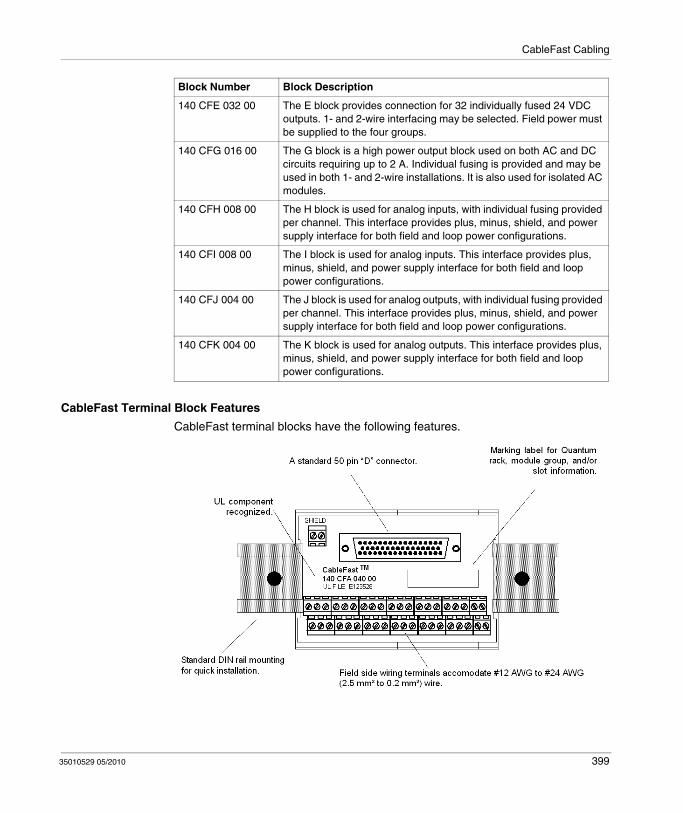
CableFast Cabling
CableFast Terminal Block Features
CableFast terminal blocks have the following features.
140 CFE 032 00 The E block provides connection for 32 individually fused 24 VDC outputs. 1- and 2-wire interfacing may be selected. Field power must be supplied to the four groups.
140 CFG 016 00 The G block is a high power output block used on both AC and DC circuits requiring up to 2 A. Individual fusing is provided and may be used in both 1- and 2-wire installations. It is also used for isolated AC modules.
140 CFH 008 00 The H block is used for analog inputs, with individual fusing provided per channel. This interface provides plus, minus, shield, and power supply interface for both field and loop power configurations.
140 CFI 008 00 The I block is used for analog inputs. This interface provides plus, minus, shield, and power supply interface for both field and loop power configurations.
140 CFJ 004 00 The J block is used for analog outputs, with individual fusing provided per channel. This interface provides plus, minus, shield, and power supply interface for both field and loop power configurations.
140 CFK 004 00 The K block is used for analog outputs. This interface provides plus, minus, shield, and power supply interface for both field and loop power configurations.
Block Number Block Description
35010529 05/2010 399
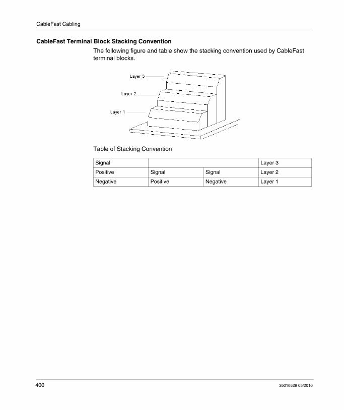
CableFast Cabling
CableFast Terminal Block Stacking Convention
The following figure and table show the stacking convention used by CableFast terminal blocks.
Table of Stacking Convention
Signal Layer 3
Positive Signal Signal Layer 2
Negative Positive Negative Layer 1
400 35010529 05/2010

CableFast Cabling
140 CFA 040 00 Quantum CableFast Cabling Block
Overview
The A block is a straight-through point-to-point connection on the terminal block. Wiring this block (and other CableFast cabling blocks) is identical to wiring the Quantum I/O connector (140 XTS 002 00).
140 CFA 040 00 Terminal Block
The following terminal block is unique to the 140 CFA 040 00 module.
Application Notes
The following are the application notes for the 140 CFA 040 00 terminal block.
1. Configuration – two columns2. Compatibility – this terminal block provides straight through (point-to-point)
connection.
NOTE: You may use this terminal block with Quantum I/O modules except the 140 ATI 030 00 thermocouple module.
140 CFA 040 00 Dimensions
35010529 05/2010 401

CableFast Cabling
140 CFA 040 00 Wiring Diagram
402 35010529 05/2010

CableFast Cabling
140 CFB 032 00 Quantum CableFast Cabling Block
Overview
The B block is used for individually fused 2-wire digital inputs. This CableFast terminal block is designed to help prevent a single point error from affecting the remaining inputs. It is not recommended for sourced 1-wire inputs (powered from the field).
Terminal Block
The following figure shows the terminal block for the 140 CFB 032 00 module.
Application Notes
The following are the application notes for the 140 CFB 0320 0 terminal block.
1. Configuration – arranged in four groups of eight I/O points. Two terminals per point help prevent disruption of service due to a single point error.
2. Compatibility – this terminal block provides individual 32 point 0.8 A fusing for the following input modules:140 DAI 353 00, 140 DAI 453 00, 140 DAI 553 00, 140 DDO 153 10, 140 DDI 353 00, and 140 DDI 853 00.
Dimensions
The following figures show the dimensions for the 140CFB03200 terminal block.
35010529 05/2010 403

CableFast Cabling
Wiring of Input Modules
The following figure shows the 140 CFB 032 00 wiring for the following input modules: 140 DAI 353 00, 140 DAI 453 00, 140 DAI 553 00, 140 DDI 353 00, and 140 DDI 853 00.
NOTE: The terminal block commoning strip, Modicon # 140 CFX 001 10 (Qty. 10) can be used to jumper the power between groups.
404 35010529 05/2010

CableFast Cabling
Wiring of Output Module
The following figure shows the 140 CFB 032 00 wiring for the 140 DDO 153 10 output module.
NOTE: The terminal block commoning strip, Modicon # 140 CFX 001 10 (Qty. 10) can be used to jumper the power between groups.
35010529 05/2010 405
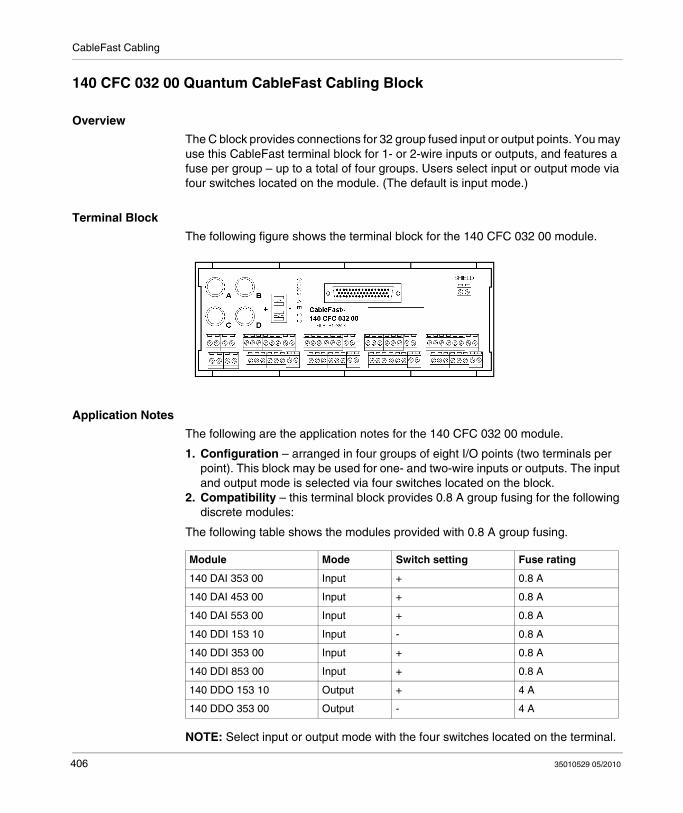
CableFast Cabling
140 CFC 032 00 Quantum CableFast Cabling Block
Overview
The C block provides connections for 32 group fused input or output points. You may use this CableFast terminal block for 1- or 2-wire inputs or outputs, and features a fuse per group – up to a total of four groups. Users select input or output mode via four switches located on the module. (The default is input mode.)
Terminal Block
The following figure shows the terminal block for the 140 CFC 032 00 module.
Application Notes
The following are the application notes for the 140 CFC 032 00 module.
1. Configuration – arranged in four groups of eight I/O points (two terminals per point). This block may be used for one- and two-wire inputs or outputs. The input and output mode is selected via four switches located on the block.
2. Compatibility – this terminal block provides 0.8 A group fusing for the following discrete modules:
The following table shows the modules provided with 0.8 A group fusing.
NOTE: Select input or output mode with the four switches located on the terminal.
Module Mode Switch setting Fuse rating
140 DAI 353 00 Input + 0.8 A
140 DAI 453 00 Input + 0.8 A
140 DAI 553 00 Input + 0.8 A
140 DDI 153 10 Input - 0.8 A
140 DDI 353 00 Input + 0.8 A
140 DDI 853 00 Input + 0.8 A
140 DDO 153 10 Output + 4 A
140 DDO 353 00 Output - 4 A
406 35010529 05/2010
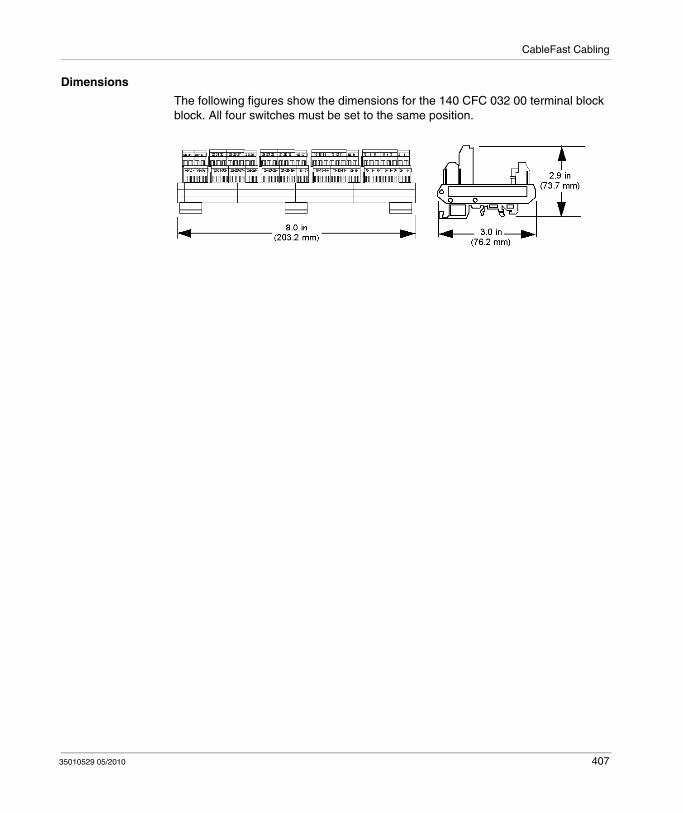
CableFast Cabling
Dimensions
The following figures show the dimensions for the 140 CFC 032 00 terminal block block. All four switches must be set to the same position.
35010529 05/2010 407

CableFast Cabling
Wiring for Input Modules
The following shows the 140 CFC 032 00 wiring for the following input modules: 140 DAI 353 00, 140 DAI 453 00, 140 DAI 553 00, 140 DDI 353 00, and 140 DDI 853 00.
NOTE: The terminal block commoning strip, Modicon # 140 CFX 001 10 (Qty. 10), can be used to jumper the power between groups.
408 35010529 05/2010

CableFast Cabling
Wiring for 140 DDI 153 10 Input Module
The following figure shows the 140 CFC 032 00 wiring for the 140 DDI 153 10 input module.
NOTE: The terminal block commoning strip, Modicon # 140 CFX 001 10 (Qty. 10), can be used to jumper the power between groups.
35010529 05/2010 409
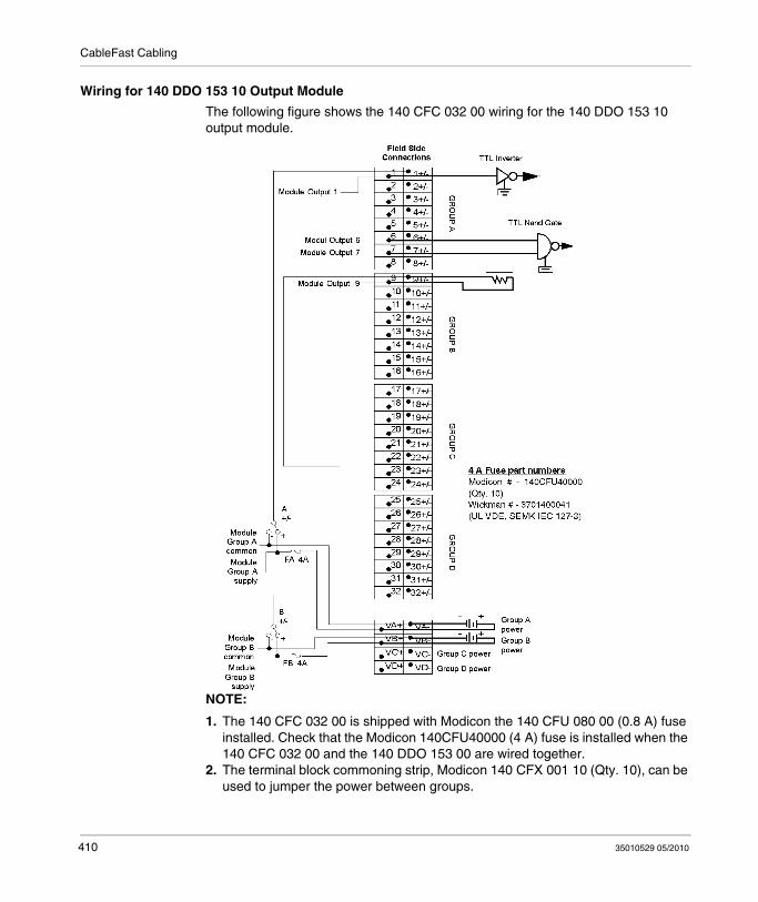
CableFast Cabling
Wiring for 140 DDO 153 10 Output Module
The following figure shows the 140 CFC 032 00 wiring for the 140 DDO 153 10 output module.
NOTE:
1. The 140 CFC 032 00 is shipped with Modicon the 140 CFU 080 00 (0.8 A) fuse installed. Check that the Modicon 140CFU40000 (4 A) fuse is installed when the 140 CFC 032 00 and the 140 DDO 153 00 are wired together.
2. The terminal block commoning strip, Modicon 140 CFX 001 10 (Qty. 10), can be used to jumper the power between groups.
410 35010529 05/2010
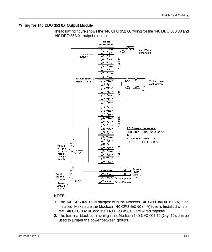
CableFast Cabling
Wiring for 140 DDO 353 0X Output Module
The following figure shows the 140 CFC 032 00 wiring for the 140 DDO 353 00 and 140 DDO 353 01 output modules.
NOTE:
1. The 140 CFC 032 00 is shipped with the Modicon 140 CFU 080 00 (0.8 A) fuse installed. Make sure the Modicon 140 CFU 400 00 (4 A) fuse is installed when the 140 CFC 032 00 and the 140 DDO 353 00 are wired together.
2. The terminal block commoning strip, Modicon 140 CFX 001 10 (Qty. 10), can be used to jumper the power between groups.
35010529 05/2010 411
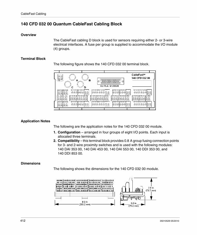
CableFast Cabling
140 CFD 032 00 Quantum CableFast Cabling Block
Overview
The CableFast cabling D block is used for sensors requiring either 2- or 3-wire electrical interfaces. A fuse per group is supplied to accommodate the I/O module (4) groups.
Terminal Block
The following figure shows the 140 CFD 032 00 terminal block.
Application Notes
The following are the application notes for the 140 CFD 032 00 module.
1. Configuration – arranged in four groups of eight I/O points. Each input is allocated three terminals.
2. Compatibility – this terminal block provides 0.8 A group fusing connection points for 3- and 2-wire proximity switches and is used with the following modules: 140 DAI 353 00, 140 DAI 453 00, 140 DAI 553 00, 140 DDI 353 00, and 140 DDI 853 00.
Dimensions
The following shows the dimensions for the 140 CFD 032 00 module.
412 35010529 05/2010

CableFast Cabling
Wiring
The following figure shows the wiring for the 140 CFD 032 00 module.
NOTE:
1. The GND (ground) terminal points are not connected.2. The terminal block commoning strip, Modicon # 140 CFX 001 10 (Qty. 10), can
be used to jumper the power between groups.
35010529 05/2010 413

CableFast Cabling
140 CFE 032 00 Quantum CableFast Cabling Block
Overview
The CableFast E cabling block provides connections for 32 individually fused 24 VDC outputs. 1- and 2-wire interfacing may be selected. Field power must be supplied to the four groups.
Terminal Block
The following figure shows the 140 CFE 032 00 terminal block.
Application Notes
The following are the application notes for the 140 CFE 032 00 module.
1. Configuration – arranged in four groups of eight I/O points. Two terminals per point help prevent disruption of service due to a single point error.
2. Compatibility – this terminal block provides individual 32-point 0.8 A fusing for the 140 DDO 353 00 and the 140 DDO 353 01 modules.
Dimensions
The following shows the dimensions for the 140 CFE 032 00 module.
414 35010529 05/2010

CableFast Cabling
Wiring Diagram
The following figure shows the wiring for the 140 CFE 032 00 module.
NOTE: The terminal block commoning strip, Modicon # 140 CFX 001 10 (QTY. 10), can be used to jumper the power between groups.
35010529 05/2010 415

CableFast Cabling
140 CFG 016 00 Quantum CableFast Cabling Block
Overview
The G CableFast cabling block is a high-power output block used on both AC and DC circuits requiring up to 2 A. Individual fusing is provided and may be used in both 1- and 2-wire installations. It is also used for isolated AC modules.
Terminal Block
The following figure shows the 140 CFG 016 00 terminal block.
Application Notes
The following are the application notes for the 140 CFG 016 00 module.
1. Configuration – Arranged in 16 isolated I/O points.2. Compatibility – This terminal block provides individual 16-point 4 A fused
connection points for the following modules: 140 DAI 340 00, 140 DAI 440 00, 140 DAI 540 00, 140 DAO 840 00, 140 DAO 840 10, 140 DAO 842 10, 140 DAO 842 20, and 140 DDO 843 00.
Dimensions
The following figures show the dimensions for the 140 CFG 016 00 module.
416 35010529 05/2010

CableFast Cabling
Wiring for Isolated AC Input Mode
The following figure shows the 140 CFG 016 00 wiring for the input (isolated AC input mode) modules: 140 DAI 340 00, 140 DAI 440 00, and 140 DAI 540 00.
NOTE:
1. The terminal block commoning strip, Modicon # 140 CFX 001 10 (Qty. 10), can be used to jumper the power between groups.
2. The GND (ground) terminal points are not connected.
35010529 05/2010 417
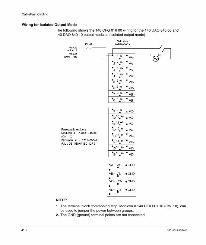
CableFast Cabling
Wiring for Isolated Output Mode
The following shows the 140 CFG 016 00 wiring for the 140 DAO 840 00 and 140 DAO 840 10 output modules (isolated output mode).
NOTE:
1. The terminal block commoning strip, Modicon # 140 CFX 001 10 (Qty. 10), can be used to jumper the power between groups.
2. The GND (ground) terminal points are not connected
418 35010529 05/2010

CableFast Cabling
Wiring for Grouped AC Output Mode
The following figure shows the 140 CFG 016 00 wiring for the 140 DAO 842 10 and 140 DAO 842 20 output modules (grouped AC output mode).
NOTE:
1. The terminal block commoning strip, Modicon # 140 CFX 001 10 (Qty. 10), can be used to jumper the power between groups.
2. The GND (ground) terminal points are not connected.
35010529 05/2010 419
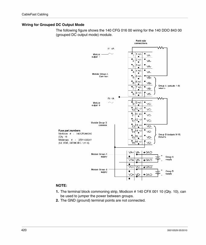
CableFast Cabling
Wiring for Grouped DC Output Mode
The following figure shows the 140 CFG 016 00 wiring for the 140 DDO 843 00 (grouped DC output mode) module.
NOTE:
1. The terminal block commoning strip, Modicon # 140 CFX 001 10 (Qty. 10), can be used to jumper the power between groups.
2. The GND (ground) terminal points are not connected.
420 35010529 05/2010
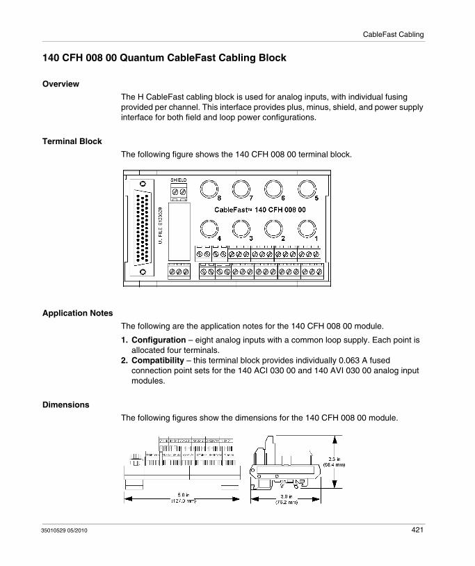
CableFast Cabling
140 CFH 008 00 Quantum CableFast Cabling Block
Overview
The H CableFast cabling block is used for analog inputs, with individual fusing provided per channel. This interface provides plus, minus, shield, and power supply interface for both field and loop power configurations.
Terminal Block
The following figure shows the 140 CFH 008 00 terminal block.
Application Notes
The following are the application notes for the 140 CFH 008 00 module.
1. Configuration – eight analog inputs with a common loop supply. Each point is allocated four terminals.
2. Compatibility – this terminal block provides individually 0.063 A fused connection point sets for the 140 ACI 030 00 and 140 AVI 030 00 analog input modules.
Dimensions
The following figures show the dimensions for the 140 CFH 008 00 module.
35010529 05/2010 421
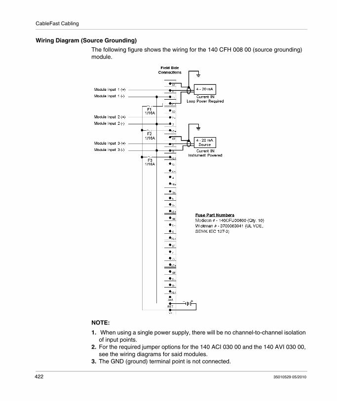
CableFast Cabling
Wiring Diagram (Source Grounding)
The following figure shows the wiring for the 140 CFH 008 00 (source grounding) module.
NOTE:
1. When using a single power supply, there will be no channel-to-channel isolation of input points.
2. For the required jumper options for the 140 ACI 030 00 and the 140 AVI 030 00, see the wiring diagrams for said modules.
3. The GND (ground) terminal point is not connected.
422 35010529 05/2010
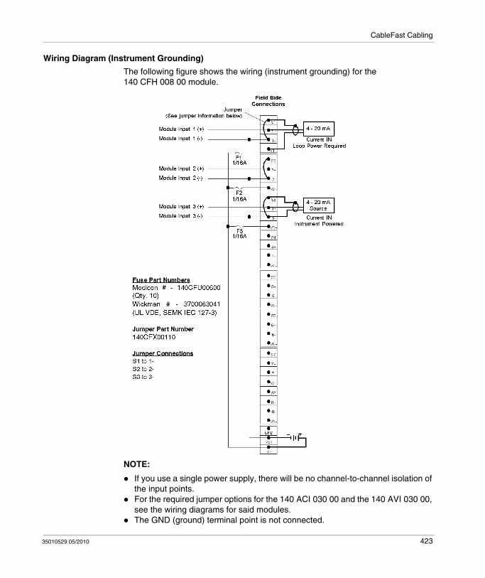
CableFast Cabling
Wiring Diagram (Instrument Grounding)
The following figure shows the wiring (instrument grounding) for the 140 CFH 008 00 module.
NOTE:
If you use a single power supply, there will be no channel-to-channel isolation of the input points.For the required jumper options for the 140 ACI 030 00 and the 140 AVI 030 00, see the wiring diagrams for said modules.The GND (ground) terminal point is not connected.
35010529 05/2010 423

CableFast Cabling
Wiring Diagram (Chassis Grounding)
The following figure shows the wiring (chassis grounding) for the 140 CFH 008 00 module.
NOTE:
1. When using a single power supply, there will be no channel-to-channel isolation of input points.
2. For the required jumper options for the 140 ACI 030 00 and the 140 AVI 030 00, see the wiring diagrams for said modules.
3. The GND (ground) terminal point is not connected.
424 35010529 05/2010

CableFast Cabling
140CFI00800 Quantum CableFast Cabling Block
Overview
The I block is used for analog inputs. This interface provides plus, minus, shield, and power supply interfaces for both field and loop power configurations.
See Common Features of the CableFast Cabling System (see Modicon Quantum, Automation Series, Hardware Reference Guide) for information on common specifications and features of CableFast cabling blocks.
Application Notes
The following are the application notes for the 140CFI00800 module.
1. Configuration – Eight analog inputs with a common loop supply. Each point is allocated four terminals.
2. Compatibility – This terminal block provides eight connection point sets for the 140ACI03000 and 140AVI03000 analog input modules.
Dimensions
The following figures show the dimensions for the 140CFI00800 module.
35010529 05/2010 425
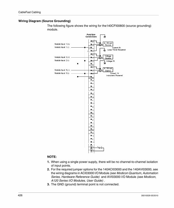
CableFast Cabling
Wiring Diagram (Source Grounding)
The following figure shows the wiring for the140CFI00800 (source grounding) module.
NOTE:
1. When using a single power supply, there will be no channel-to-channel isolation of input points.
2. For the required jumper options for the 140ACI03000 and the 140AVI03000, see the wiring diagrams in ACI03000 I/O Module (see Modicon Quantum, Automation Series, Hardware Reference Guide) and AVI03000 I/O Module (see Modicon, A120 Series I/O Modules, User Guide) .
3. The GND (ground) terminal point is not connected.
426 35010529 05/2010
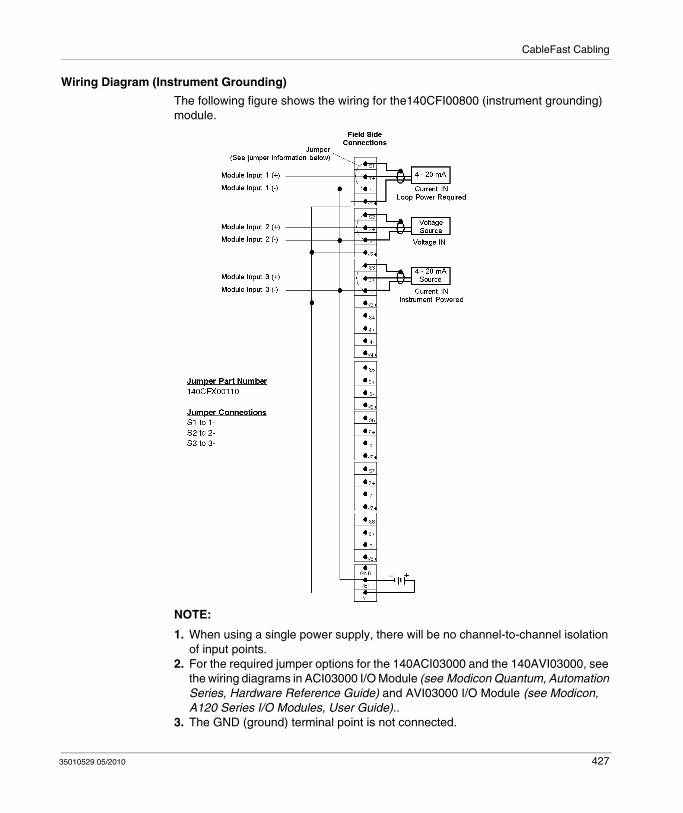
CableFast Cabling
Wiring Diagram (Instrument Grounding)
The following figure shows the wiring for the140CFI00800 (instrument grounding) module.
NOTE:
1. When using a single power supply, there will be no channel-to-channel isolation of input points.
2. For the required jumper options for the 140ACI03000 and the 140AVI03000, see the wiring diagrams in ACI03000 I/O Module (see Modicon Quantum, Automation Series, Hardware Reference Guide) and AVI03000 I/O Module (see Modicon, A120 Series I/O Modules, User Guide)..
3. The GND (ground) terminal point is not connected.
35010529 05/2010 427
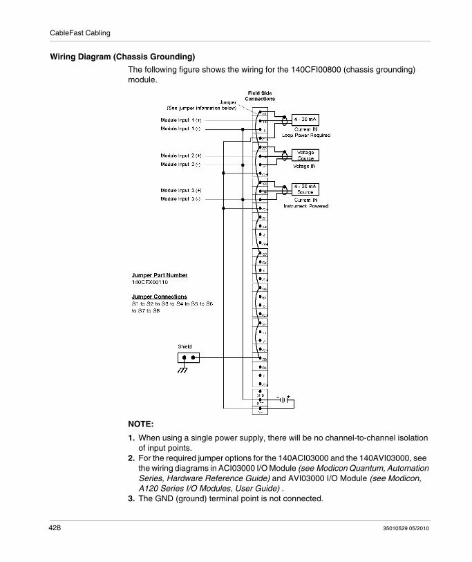
CableFast Cabling
Wiring Diagram (Chassis Grounding)
The following figure shows the wiring for the 140CFI00800 (chassis grounding) module.
NOTE:
1. When using a single power supply, there will be no channel-to-channel isolation of input points.
2. For the required jumper options for the 140ACI03000 and the 140AVI03000, see the wiring diagrams in ACI03000 I/O Module (see Modicon Quantum, Automation Series, Hardware Reference Guide) and AVI03000 I/O Module (see Modicon, A120 Series I/O Modules, User Guide) .
3. The GND (ground) terminal point is not connected.
428 35010529 05/2010
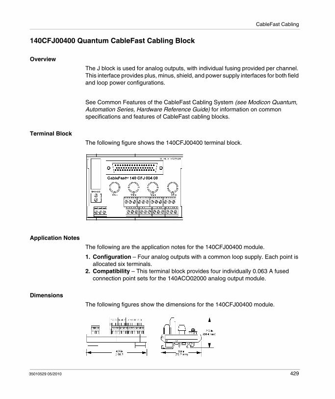
CableFast Cabling
140CFJ00400 Quantum CableFast Cabling Block
Overview
The J block is used for analog outputs, with individual fusing provided per channel. This interface provides plus, minus, shield, and power supply interfaces for both field and loop power configurations.
See Common Features of the CableFast Cabling System (see Modicon Quantum, Automation Series, Hardware Reference Guide) for information on common specifications and features of CableFast cabling blocks.
Terminal Block
The following figure shows the 140CFJ00400 terminal block.
Application Notes
The following are the application notes for the 140CFJ00400 module.
1. Configuration – Four analog outputs with a common loop supply. Each point is allocated six terminals.
2. Compatibility – This terminal block provides four individually 0.063 A fused connection point sets for the 140ACO02000 analog output module.
Dimensions
The following figures show the dimensions for the 140CFJ00400 module.
35010529 05/2010 429
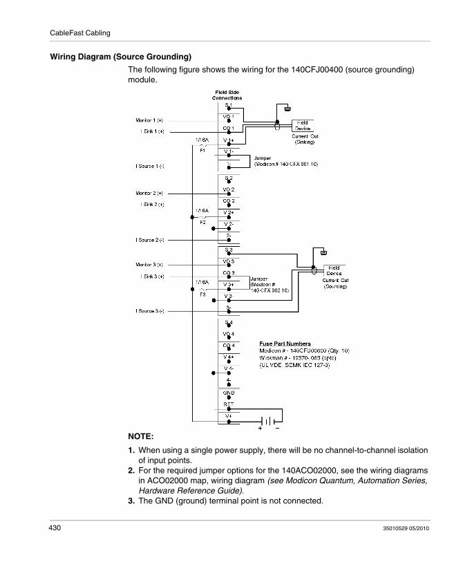
CableFast Cabling
Wiring Diagram (Source Grounding)
The following figure shows the wiring for the 140CFJ00400 (source grounding) module.
NOTE:
1. When using a single power supply, there will be no channel-to-channel isolation of input points.
2. For the required jumper options for the 140ACO02000, see the wiring diagrams in ACO02000 map, wiring diagram (see Modicon Quantum, Automation Series, Hardware Reference Guide).
3. The GND (ground) terminal point is not connected.
430 35010529 05/2010
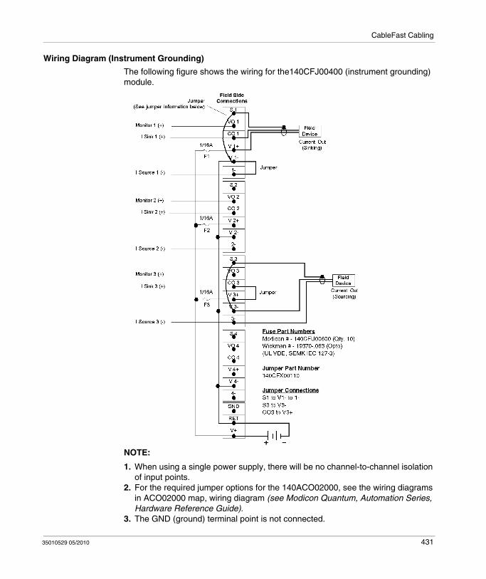
CableFast Cabling
Wiring Diagram (Instrument Grounding)
The following figure shows the wiring for the140CFJ00400 (instrument grounding) module.
NOTE:
1. When using a single power supply, there will be no channel-to-channel isolation of input points.
2. For the required jumper options for the 140ACO02000, see the wiring diagrams in ACO02000 map, wiring diagram (see Modicon Quantum, Automation Series, Hardware Reference Guide).
3. The GND (ground) terminal point is not connected.
35010529 05/2010 431

CableFast Cabling
Wiring Diagram (Chassis Grounding)
The following figure shows the wiring for the 140CFJ00400 (chassis grounding) module.
NOTE:
1. When using a single power supply, there will be no channel-to-channel isolation of input points.
2. For the required jumper options for the 140ACO02000, see the wiring diagrams in ACO02000 map, wiring diagram (see Modicon Quantum, Automation Series, Hardware Reference Guide).
3. The GND (ground) terminal point is not connected.
432 35010529 05/2010

CableFast Cabling
140CFK00400 Quantum CableFast Cabling Block
Overview
The K block is used for analog outputs. This interface provides plus, minus, shield, and power supply interface for both field and loop power configurations.
See Common Features of the CableFast Cabling System (see Modicon Quantum, Automation Series, Hardware Reference Guide) for information on common specifications and features of CableFast cabling blocks.
Terminal Block
The following figure shows the 140CFK00400 terminal block.
Application Notes
The following are the application notes for the 140CFK00400 module.
1. Configuration – Four analog outputs with a common loop supply. Each point is allocated four terminals.
2. Compatibility – This terminal block provides four individually unfused connection point sets for the 140ACO02000 and 140AVO02000 analog output modules.
Dimensions
The following figures show the dimensions for the 140CFK00400 module.
35010529 05/2010 433
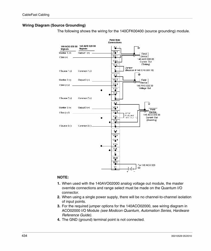
CableFast Cabling
Wiring Diagram (Source Grounding)
The following shows the wiring for the 140CFK00400 (source grounding) module.
NOTE:
1. When used with the 140AVO02000 analog voltage out module, the master override connections and range select must be made on the Quantum I/O connector.
2. When using a single power supply, there will be no channel-to-channel isolation of input points.
3. For the required jumper options for the 140ACO02000, see wiring diagram in ACO02000 I/O Module (see Modicon Quantum, Automation Series, Hardware Reference Guide).
4. The GND (ground) terminal point is not connected.
434 35010529 05/2010
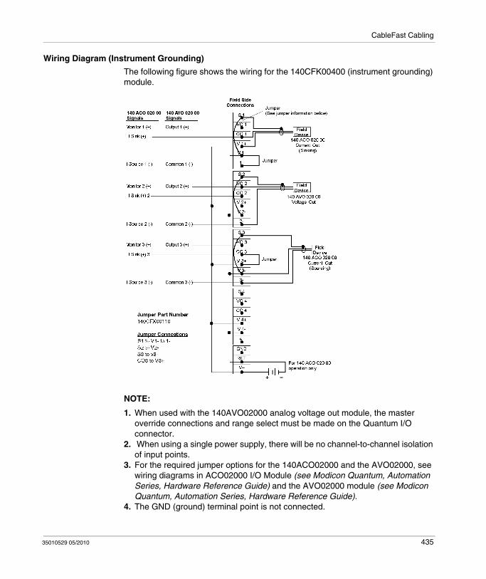
CableFast Cabling
Wiring Diagram (Instrument Grounding)
The following figure shows the wiring for the 140CFK00400 (instrument grounding) module.
NOTE:
1. When used with the 140AVO02000 analog voltage out module, the master override connections and range select must be made on the Quantum I/O connector.
2. When using a single power supply, there will be no channel-to-channel isolation of input points.
3. For the required jumper options for the 140ACO02000 and the AVO02000, see wiring diagrams in ACO02000 I/O Module (see Modicon Quantum, Automation Series, Hardware Reference Guide) and the AVO02000 module (see Modicon Quantum, Automation Series, Hardware Reference Guide).
4. The GND (ground) terminal point is not connected.
35010529 05/2010 435
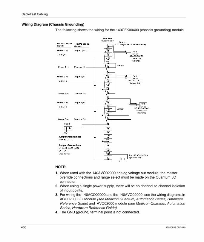
CableFast Cabling
Wiring Diagram (Chassis Grounding)
The following shows the wiring for the 140CFK00400 (chassis grounding) module.
NOTE:
1. When used with the 140AVO02000 analog voltage out module, the master override connections and range select must be made on the Quantum I/O connector.
2. When using a single power supply, there will be no channel-to-channel isolation of input points.
3. For wiring the 140ACO02000 and the 140AVO02000, see the wiring diagrams in ACO02000 I/O Module (see Modicon Quantum, Automation Series, Hardware Reference Guide) and AVO02000 module (see Modicon Quantum, Automation Series, Hardware Reference Guide).
4. The GND (ground) terminal point is not connected.
436 35010529 05/2010

CableFast Cabling
CableFast Cables
Cable Specifications
Cable Lengths
Standard Power
Cable Diameter 0.43 in. nominal (10.9 mm)
Number of Conductors 8-#20 AWG (0.8 mm), 7/28 tinned annealed copper; semi rigid PVC32-#26 AWG (0.4 mm), 7/34 tinned annealed copper; semi rigid PVC
Bend Radius (I.D.) 0.75 in. min. (19.0 mm)
High Power
Cable Diameter 0.55 in. nominal (14.0 mm)
Number of Conductors 8-#18 AWG (1.0 mm), 16/30 tinned annealed copper; semi rigid PVC32-#20 AWG (0.8 mm), 10/30 tinned annealed copper; semi rigid PVC
Bend Radius (I.D.) 38.1 mm (1.50 in) min.
Common Specifications
Cable Jacket Jacket color: black, 0.040 in wall min, flexible PVC
Wire Strip Length 8 mm (0.32 in)
Wire Marking See the wire color coding table
Wire Rating 300 V, 105 ° C UL rated 2517, CSA Type AWM 1/2 FT1
Cable Rating 300 V, 105 ° C rated
Shielding Aluminum/polyester tape (aluminum side out) attached at connector body (360 ° ).#22 AWG, 7/30 drain wire.Shield resistance 16.55 Ω/M ft nominal
Agency Approval UL-758; AWM style 2517 VW-1 and CSA C22:210.2; AWM I/II A/B FT1
Cable Lengths Terminated Pigtail
Standard Power High Power High Power
0.91 m (3 ft) X X
1.82 m (6 ft) X X X
2.73 m (9 ft) X X
3.64 m (12 ft) X X
4.6 m (15 ft) X
35010529 05/2010 437

CableFast Cabling
Inner Wire Color Codes
The following diagram represents the physical mapping of colors on the standard cablefast wires:
The following table describes the colors mapping of the standard cablefast wires:
Wire/ Pin #
AWG for Standard Power Cable
AWG for High Power Cable
Color Wire/ Pin #
AWG for Standard Power Cable
AWG for High Power Cable
Color
1 26 20 Black 21 26 20 White/Blue
2 26 20 Brown 22 26 20 White/Violet
3 26 20 Red 23 26 20 White/Gray
4 26 20 Orange 24 26 20 White/ Black/ Brown
5 26 20 Yellow 25 26 20 White/ Black/ Red
6 26 20 Green 26 26 20 White/ Black/ Orange
7 26 20 Blue 27 26 20 White/ Black/ Yellow
8 26 20 Violet 28 26 20 White/ Black/ Green
9 20 18 Black 29 20 20 Yellow
10 20 18 Brown 30 20 18 Green
11 26 20 Gray 31 26 18 White/ Black/ Blue
12 26 20 White 32 26 20 White/ Black/ Violet
13 26 20 White/ Black 33 26 20 White/ Black/ Gray
14 26 20 White/ Brown 34 26 20 White/ Brown/ Red
15 26 20 White/ Red 35 26 20 White/ Brown/ Orange
16 26 20 White/ Orange
36 26 20 White/ Brown/ Yellow
17 26 20 White/Yellow 37 26 20 White/ Brown/ Green
18 26 20 White/ Green 38 26 20 White/ Brown/ Blue
19 20 18 Red 39 20 18 Blue
20 20 18 Orange 40 20 18 Violet
438 35010529 05/2010

CableFast Cabling
The following diagram represents the physical mapping of colors on the substitution cablefast wires:
The following table describes the colors mapping of the substitution cablefast wires:
Wire/ Pin #
AWG for Standard Power Cable
AWG for High Power Cable
Color Wire/ Pin #
AWG for Standard Power Cable
AWG for High Power Cable
Color
1 26 20 Black 21 26 20 White/Blue
2 26 20 Brown 22 26 20 White/Violet
3 26 20 Red 23 26 20 White/Gray
4 26 20 Orange 24 26 20 Black/ Brown
5 26 20 Yellow 25 26 20 Black/ Red
6 26 20 Green 26 26 20 Black/ Orange
7 26 20 Blue 27 26 20 Black/ Yellow
8 26 20 Violet 28 26 20 Black/ Green
9 20 18 Black 29 20 20 Yellow
10 20 18 Brown 30 20 18 Green
11 26 20 Gray 31 26 18 Black/ Blue
12 26 20 White 32 26 20 Black/ Violet
13 26 20 White/ Black 33 26 20 Black/ Gray
14 26 20 White/ Brown 34 26 20 Brown/ Red
15 26 20 White/ Red 35 26 20 Brown/ Orange
16 26 20 White/ Orange 36 26 20 Brown/ Yellow
17 26 20 White/Yellow 37 26 20 Brown/ Green
18 26 20 White/ Green 38 26 20 Brown/ Blue
19 20 18 Red 39 20 18 Blue
20 20 18 Orange 40 20 18 Violet
35010529 05/2010 439

CableFast Cabling
140 XTS Terminated Cables
I/O Connector
140 XCA 102 Pigtails
Part Number Cable Type Cable Description
Standard Power
High Power
140 XTS 002 03 X CableFast system cable with Quantum I/O connector, 0.9 m (3 ft) and D-sub connector140 XTS 012 03 X
140 XTS 002 06 X CableFast system cable with Quantum I/O connector, 1.8 m (6 ft) and D-sub connector140 XTS 012 06 X
140 XTS 002 09 X CableFast system cable with Quantum I/O connector, 2.7 m (9 ft) and D-sub connector140 XTS 012 09 X
140 XTS 002 12 X CableFast system cable with Quantum I/O connector, 3.7 m (12 ft) and D-sub connector
140 XTS 012 12 X
Part Number Cable Type Cable Description
Standard Power
High Power
140 XCA 102 06 X CableFast system cable, 6 ft (1.8 m), with D-sub connector and pigtails
140 XCA 102 15 X CableFast system cable, 4.6 m (15 ft), with D-sub connector and pigtails
440 35010529 05/2010

CableFast Cabling
Pigtail Leads
140 XTS 102 Pigtails
I/O Connector for Pigtail Leads
Part Number Cable Type Cable Description
Standard Power
High Power
140 XTS 102 06 X CableFast system cable with Quantum I/O connector, 1.8 m (6 ft), and pigtail cable
140 XTS 102 15 X CableFast system cable with Quantum I/O connector, 4.6 m (15 ft), and pigtail cable
35010529 05/2010 441

CableFast Cabling
CableFast Accessories
Overview
The following information pertains to the CableFast accessories.
Accessories
The following table shows the part numbers and descriptions for CableFast Accessories.
Terminal Block Common Strip
The following figure shows the terminal block common strip.
Jumper, Fuse Replacement
Fuse replacement information is given in the following table.
The following figure shows a jumper.
NOTE: The jumper is used instead of fuses as a disconnect device.
Part Number Description Quantity
140CFU40000 Fuse Kit, Wickmann 4 A 10
140CFU08000 Fuse Kit, Wickmann 0.8 A 10
140CFU00600 Fuse Kit, Wickmann 0.063 A 10
140CFX00110 Terminal Block Common Strip, 10 Position (see below)
10
Part Number Description Quantity
140 CFX 002 10 Jumper, Fuse Replacement (see below) 10
442 35010529 05/2010
35010529 05/2010
E
ConneXium
35010529 05/2010
ConneXium Ethernet Cabling System
Purpose
This appendix provides an overview on the ConneXium Ethernet Cabling System.
NOTE: For further details see , page , ConneXium Ethernet Cabling System Quick Reference Guide
What's in this Chapter?
This chapter contains the following topics:
Topic Page
Introduction 444
Configuration 446
443
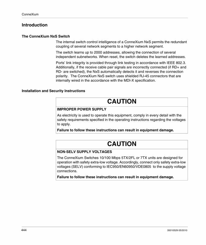
ConneXium
Introduction
The ConneXium NxS Switch
The internal switch control intelligence of a ConneXium NxS permits the redundant coupling of several network segments to a higher network segment.
The switch learns up to 2000 addresses, allowing the connection of several independent subnetworks. When reset, the switch deletes the learned addresses.
Ports’ link integrity is provided through link testing in accordance with IEEE 802.3. Additionally, if the receive cable pair signals are incorrectly connected (if RD+ and RD- are switched), the NxS automatically detects it and reverses the connection polarity. The ConneXium NxS switch uses shielded RJ-45 connectors that are internally wired in the accordance with the MDI-X specification.
Installation and Security Instructions
CAUTIONIMPROPER POWER SUPPLY
As electricity is used to operate this equipment, comply in every detail with the safety requirements specified in the operating instructions regarding the voltages to apply.
Failure to follow these instructions can result in equipment damage.
CAUTIONNON-SELV SUPPLY VOLTAGES
The ConneXium Switches 10/100 Mbps 5TX/2FL or 7TX units are designed for operation with safety extra-low voltage. Accordingly, connect only safety extra-low voltages (SELV) conforming to IEC950/EN60950/VDE0805 to the supply voltage connections.
Failure to follow these instructions can result in equipment damage.
444 35010529 05/2010
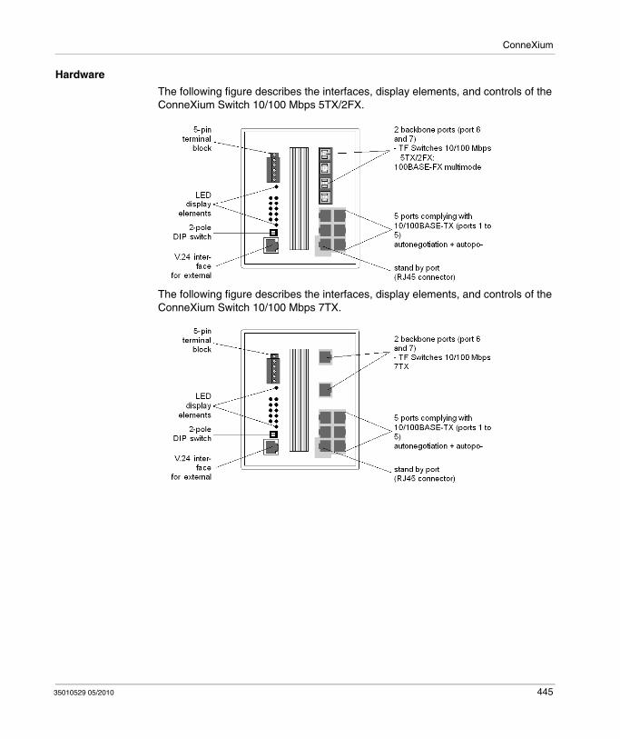
ConneXium
Hardware
The following figure describes the interfaces, display elements, and controls of the ConneXium Switch 10/100 Mbps 5TX/2FX.
The following figure describes the interfaces, display elements, and controls of the ConneXium Switch 10/100 Mbps 7TX.
35010529 05/2010 445

ConneXium
Configuration
Line Structure
The NxS switches enable backbones in line structures to be built up. Cascading is carried out using the backbone ports.
Redundant Ring Structure
With the redundancy manager function of the NxS modules you can close the two ends of a line structured backbone to a redundant ring. The NxS switches are integrated into the ring via the backbone ports (ports 6 and 7). If one section becomes inoperable the reaction time comes to less than 0.5 s at up to 50 NxS modules being cascaded.
Redundant Coupling of Network Segments
The built-in control intelligence of the NxS allows the redundant coupling of network segments.
The connection of two network segments is realized via two separate paths. The NxS switches in the redundant line get the redundancy function assigned by the DIP switch setting standby.
The NxS modules in the redundant line and the NxS switches in the main line share their operating states via the control line (crossover Ethernet cable).
After the failure of the main line the redundant NxS modules enable the redundant line within 0.5 s. If the main line is okay again, the NxS switches in the main line inform the redundant Nxs modules about this. The main line will be enabled and the redundant line will be disabled within 0.5 s.
The following figure shows an optical line structure.
446 35010529 05/2010
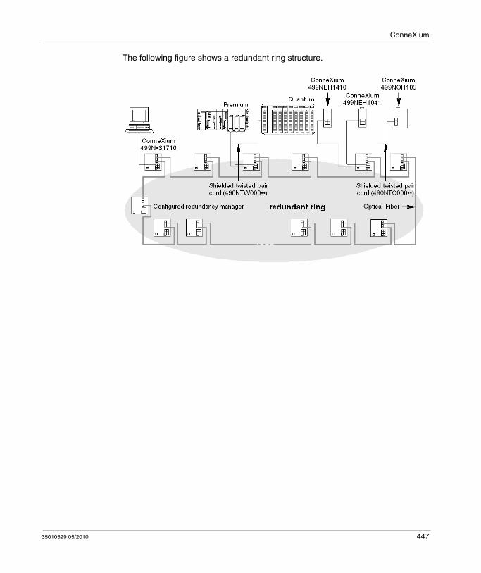
ConneXium
The following figure shows a redundant ring structure.
35010529 05/2010 447

ConneXium
The following figure shows a redundant coupling of optical rings.
448 35010529 05/2010

35010529 05/2010
F
Agency Approvals and Conformal Coating
35010529 05/2010
Agency Approvals and Conformal Coating
Introduction
This appendix provides information on agency approvals and includes conformal coating availability of the indicated Quantum products.
The table below describes the headings used in the tables in this chapter.
What's in this Chapter?
This chapter contains the following topics:
Heading Description
UL 508 certified by Underwriters Laboratories according to UL 508
c-UL (UL for Canada) certified by Underwriters Laboratories according to relevant Canadian standards (CSA)
CSA 22.2-142 certified by Canadian Standards Association according to CSA
22.2 no 142
FM (Class I, Division 2) certified by Factory Mutual for Hazardous Locations Class 1 Division 2
CE compliant to the EMC and Low Voltage European Directives
Topic Page
Agency Approvals: Power Supply 450
Agency Approvals: CPU 451
Agency Approvals: I/O 452
Agency Approvals: DIO Drops 454
Agency Approvals: RIO Heads and Drops 455
Agency Approvals: Ethernet Modules 456
Agency Approvals: NOM 457
Agency Approvals: Motion Modules 458
Agency Approvals: Battery and Simulator Modules 459
449

Agency Approvals and Conformal Coating
Agency Approvals: Power Supply
Power Supplies Table
The following table provides the agency approvals and conformal coating availability for the power supplies of the indicated Quantum products.
Quantum Part Numbers
Availability of a conformal coated version
Agency Approval Status
UL 508 c-UL (UL for Canada)
CSA 22.2-142
FM Class I, Div 2
CE
140 CPS 111 00 y y y y y y
140 CPS 114 00 y y y y y y
140 CPS 114 10 y y y y y y
140 CPS 114 20 y y y y y y
140 CPS 124 00 y y y y y y
140 CPS 124 20 y y y y y y
140 CPS 211 00 y y y y y y
140 CPS 214 00 y y y y y y
140 CPS 224 00 y y y y y y
140 CPS 414 00 y y y y y y
140 CPS 424 00 y y y y y y
140 CPS 511 00 y y y y y y
140 CPS 524 00 y y y y y y
450 35010529 05/2010
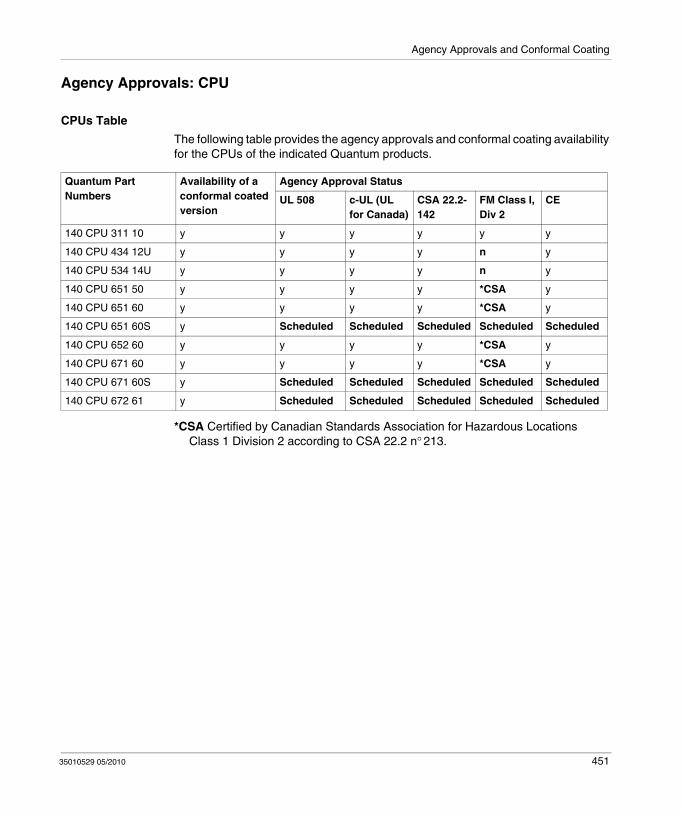
Agency Approvals and Conformal Coating
Agency Approvals: CPU
CPUs Table
The following table provides the agency approvals and conformal coating availability for the CPUs of the indicated Quantum products.
*CSA Certified by Canadian Standards Association for Hazardous Locations Class 1 Division 2 according to CSA 22.2 n° 213.
Quantum Part Numbers
Availability of a conformal coated version
Agency Approval Status
UL 508 c-UL (UL for Canada)
CSA 22.2-142
FM Class I, Div 2
CE
140 CPU 311 10 y y y y y y
140 CPU 434 12U y y y y n y
140 CPU 534 14U y y y y n y
140 CPU 651 50 y y y y *CSA y
140 CPU 651 60 y y y y *CSA y
140 CPU 651 60S y Scheduled Scheduled Scheduled Scheduled Scheduled
140 CPU 652 60 y y y y *CSA y
140 CPU 671 60 y y y y *CSA y
140 CPU 671 60S y Scheduled Scheduled Scheduled Scheduled Scheduled
140 CPU 672 61 y Scheduled Scheduled Scheduled Scheduled Scheduled
35010529 05/2010 451

Agency Approvals and Conformal Coating
Agency Approvals: I/O
I/O Table
The following table provides the agency approvals and conformal coating availability for the I/O of the indicated Quantum products
Quantum Part Numbers
Availability of a conformal coated version
Agency Approval Status
UL 508 c-UL (UL for Canada)
CSA 22.2-142
FM Class I, Div 2
CE
140 ACI 030 00 y y y y y y
140 ACI 040 00 y y y y y y
140 ACO 020 00 y y y y y y
140 ACO 130 00 y y y y y y
140 AII 330 00 y y y y y y
140 AII 330 10 y y y y y y
140 AIO 330 00 y y y y y y
140 AMM 090 00 y y y y y y
140 ARI 030 10 y y y y y y
140 ATI 030 00 y y y y y y
140 AVI 030 00 y y y y y y
140 AVO 020 00 y y y y y y
140 DAI 340 00 y y y y y y
140 DAI 353 00 y y y y y y
140 DAI 440 00 y y y y y y
140 DAI 453 00 y y y y y y
140 DAI 540 00 y y y y y y
140 DAI 543 00 y y y y y y
140 DAI 553 00 y y y y y y
140 DAI 740 00 y y y y y y
140 DAI 753 00 y y y y n y
140 DAM 590 00 y y y y y y
140 DAO 840 00 y y y y y y
140 DAO 840 10 y y y y y y
140 DAO 842 10 y y y y y y
140 DAO 842 20 y y y y y y
140 DAO 853 00 y y y y n y
452 35010529 05/2010
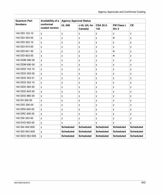
Agency Approvals and Conformal Coating
140 DDI 153 10 y y y y y y
140 DDI 353 00 y y y y n y
140 DDI 353 10 y y y y y y
140 DDI 673 00 y y y y y y
140 DDI 841 00 y y y y n y
140 DDI 853 00 y y y y n y
140 DDM 390 00 y y y y y y
140 DDM 690 00 y y y y y y
140 DDO 153 10 y y y y y y
140 DDO 353 00 y y y y y y
140 DDO 353 01 y y y y y y
140 DDO 353 10 y y y y y y
140 DDO 364 00 y y y y y y
140 DDO 843 00 y y y y y y
140 DDO 885 00 y y y y y y
140 DII 330 00 y y y y y y
140 DIO 330 00 y y y y y y
140 DRA 840 00 y y y y y y
140 DRC 830 00 y y y y y y
140 DSI 353 00 y y y y y y
140 DVO 853 00 y y y y y y
140 SAI 940 00S y Scheduled Scheduled Scheduled Scheduled Scheduled
140 SDI 953 00S y Scheduled Scheduled Scheduled Scheduled Scheduled
140 SDO 953 00S y Scheduled Scheduled Scheduled Scheduled Scheduled
Quantum Part Numbers
Availability of a conformal coated version
Agency Approval Status
UL 508 c-UL (UL for Canada)
CSA 22.2-142
FM Class I, Div 2
CE
35010529 05/2010 453
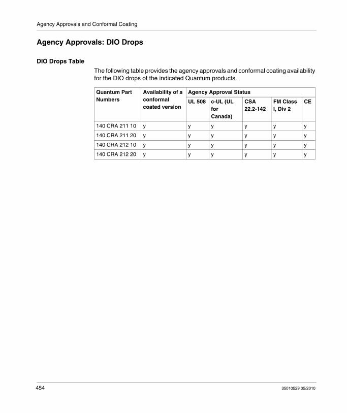
Agency Approvals and Conformal Coating
Agency Approvals: DIO Drops
DIO Drops Table
The following table provides the agency approvals and conformal coating availability for the DIO drops of the indicated Quantum products.
Quantum Part Numbers
Availability of a conformal coated version
Agency Approval Status
UL 508 c-UL (UL for Canada)
CSA 22.2-142
FM Class I, Div 2
CE
140 CRA 211 10 y y y y y y
140 CRA 211 20 y y y y y y
140 CRA 212 10 y y y y y y
140 CRA 212 20 y y y y y y
454 35010529 05/2010

Agency Approvals and Conformal Coating
Agency Approvals: RIO Heads and Drops
RIO Heads and Drops Table
The following table provides the agency approvals and conformal coating availability for the RIO Heads and Drops of the indicated Quantum products.
Quantum Part Numbers
Availability of a conformal coated version
Agency Approval Status
UL 508 c-UL (UL for Canada)
CSA 22.2-142
FM Class I, Div 2
CE
140 CRA 931 00 y y y y y y
140 CRA 931 01 y y y y y y
140 CRA 932 00 y y y y y y
140 CRP 931 00 y y y y y y
140 CRP 932 00 y y y y y y
35010529 05/2010 455
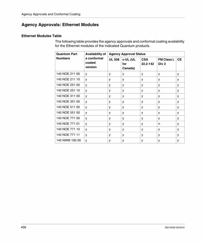
Agency Approvals and Conformal Coating
Agency Approvals: Ethernet Modules
Ethernet Modules Table
The following table provides the agency approvals and conformal coating availability for the Ethernet modules of the indicated Quantum products.
Quantum Part Numbers
Availability of a conformal coated version
Agency Approval Status
UL 508 c-UL (UL for Canada)
CSA 22.2-142
FM Class I, Div 2
CE
140 NOE 211 00 y y y y y y
140 NOE 211 10 y y y y y y
140 NOE 251 00 y y y y y y
140 NOE 251 10 y y y y y y
140 NOE 311 00 y y y y y y
140 NOE 351 00 y y y y y y
140 NOE 511 00 y y y y y y
140 NOE 551 00 y y y y y y
140 NOE 771 00 y y y y y y
140 NOE 771 01 y y y y n y
140 NOE 771 10 y y y y y y
140 NOE 771 11 y y y y y y
140 NWM 100 00 y y y y y y
456 35010529 05/2010

Agency Approvals and Conformal Coating
Agency Approvals: NOM
NOM modules Table
The following table provides the agency approvals and conformal coating availability for the NOM modules of the indicated Quantum products.
Quantum Part Numbers
Availability of a conformal coated version
Agency Approval Status
UL 508 c-UL (UL for Canada)
CSA 22.2-142
FM Class I, Div 2
CE
140 NOM 211 00 y y y y y y
140 NOM 212 00 y y y y y y
140 NOM 252 00 y y y y y y
35010529 05/2010 457
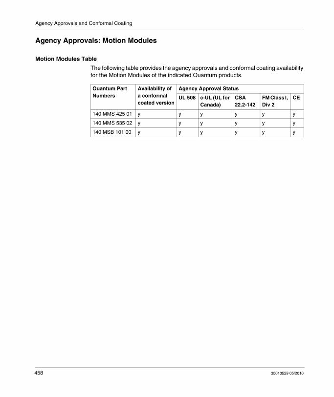
Agency Approvals and Conformal Coating
Agency Approvals: Motion Modules
Motion Modules Table
The following table provides the agency approvals and conformal coating availability for the Motion Modules of the indicated Quantum products.
Quantum Part Numbers
Availability of a conformal coated version
Agency Approval Status
UL 508 c-UL (UL for Canada)
CSA 22.2-142
FM Class I, Div 2
CE
140 MMS 425 01 y y y y y y
140 MMS 535 02 y y y y y y
140 MSB 101 00 y y y y y y
458 35010529 05/2010

Agency Approvals and Conformal Coating
Agency Approvals: Battery and Simulator Modules
Battery and Simulator Table
The following table provides the agency approvals and conformal coating availability for the battery and simulators modules of the indicated Quantum products.
Quantum Part Numbers
Availability of a conformal coated version
Agency Approval Status
UL 508 c-UL (UL for Canada)
CSA 22.2-142
FM Class I, Div 2
CE
140 XCP 900 00 y y y y y y
140 XSM 002 00 n y y y n y
140 XSM 010 00 n y y y n y
35010529 05/2010 459

Agency Approvals and Conformal Coating
460 35010529 05/2010

35010529 05/2010
G
System Specifications
35010529 05/2010
System Specifications
Purpose
This appendix provides an overview on the Quantum System Specifications.
What's in this Chapter?
This chapter contains the following topics:
Topic Page
Mechanical and Electrical Specifications 462
Power Supply Specifications 463
I/O Module Specifications 464
Operating and Storage Conditions 465
461
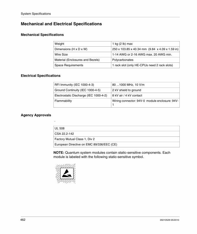
System Specifications
Mechanical and Electrical Specifications
Mechanical Specifications
Electrical Specifications
Agency Approvals
.
NOTE: Quantum system modules contain static-sensitive components. Each module is labeled with the following static-sensitive symbol.
Weight 1 kg (2 lb) max
Dimensions (H x D x W) 250 x 103.85 x 40.34 mm (9.84 x 4.09 x 1.59 in)
Wire Size 1-14 AWG or 2-16 AWG max. 20 AWG min.
Material (Enclosures and Bezels) Polycarbonates
Space Requirements 1 rack slot (only HE-CPUs need 2 rack slots)
RFI Immunity (IEC 1000-4-3) 80 ...1000 MHz, 10 V/m
Ground Continuity (IEC 1000-4-5) 2 kV shield to ground
Electrostatic Discharge (IEC 1000-4-2) 8 kV air / 4 kV contact
Flammability Wiring connector: 94V-0 module enclosure: 94V-1
UL 508
CSA 22.2-142
Factory Mutual Class 1, Div 2
European Directive on EMC 89/336/EEC (CE)
462 35010529 05/2010

System Specifications
Power Supply Specifications
AC/DC Power Supplies
Fast transients (IEC 1000-4-4) 2 kV common mode
Damped ocillatory transients 2 kV common mode.
1 kV differential mode
Surge withstand capability (transients) (IEC 1000-4-5)
2 kV common mode
1 kV differential mode
Nonperiodic peak input voltage 2.3 times nominal for 1.3 ms(Nominal = DC average or AC peak)
35010529 05/2010 463
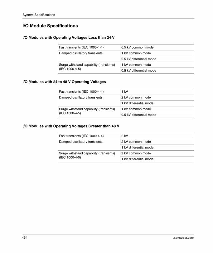
System Specifications
I/O Module Specifications
I/O Modules with Operating Voltages Less than 24 V
I/O Modules with 24 to 48 V Operating Voltages
I/O Modules with Operating Voltages Greater than 48 V
Fast transients (IEC 1000-4-4) 0.5 kV common mode
Damped oscillatory transients 1 kV common mode
0.5 kV differential mode
Surge withstand capability (transients) (IEC 1000-4-5)
1 kV common mode
0.5 kV differential mode
Fast transients (IEC 1000-4-4) 1 kV
Damped oscillatory transients 2 kV common mode
1 kV differential mode
Surge withstand capability (transients) (IEC 1000-4-5)
1 kV common mode
0.5 kV differential mode
Fast transients (IEC 1000-4-4) 2 kV
Damped oscillatory transients 2 kV common mode
1 kV differential mode
Surge withstand capability (transients) (IEC 1000-4-5)
2 kV common mode
1 kV differential mode
464 35010529 05/2010
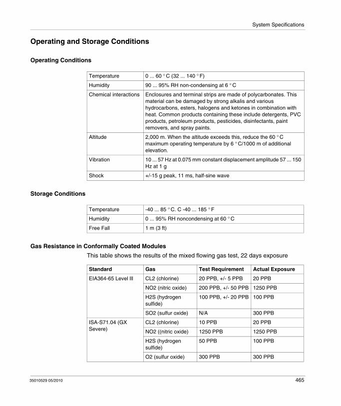
System Specifications
Operating and Storage Conditions
Operating Conditions
Storage Conditions
Gas Resistance in Conformally Coated Modules
This table shows the results of the mixed flowing gas test, 22 days exposure
Temperature 0 ... 60 ° C (32 ... 140 ° F)
Humidity 90 ... 95% RH non-condensing at 6 ° C
Chemical interactions Enclosures and terminal strips are made of polycarbonates. This material can be damaged by strong alkalis and various hydrocarbons, esters, halogens and ketones in combination with heat. Common products containing these include detergents, PVC products, petroleum products, pesticides, disinfectants, paint removers, and spray paints.
Altitude 2,000 m. When the altitude exceeds this, reduce the 60 ° C maximum operating temperature by 6 ° C/1000 m of additional elevation.
Vibration 10 ... 57 Hz at 0.075 mm constant displacement amplitude 57 ... 150 Hz at 1 g
Shock +/-15 g peak, 11 ms, half-sine wave
Temperature -40 ... 85 ° C. C -40 ... 185 ° F
Humidity 0 ... 95% RH noncondensing at 60 ° C
Free Fall 1 m (3 ft)
Standard Gas Test Requirement Actual Exposure
EIA364-65 Level lll CL2 (chlorine) 20 PPB, +/- 5 PPB 20 PPB
NO2 (nitric oxide) 200 PPB, +/- 50 PPB 1250 PPB
H2S (hydrogen sulfide)
100 PPB, +/- 20 PPB 100 PPB
SO2 (sulfur oxide) N/A 300 PPB
ISA-S71.04 (GX Severe)
CL2 (chlorine) 10 PPB 20 PPB
NO2 ((nitric oxide) 1250 PPB 1250 PPB
H2S (hydrogen sulfide)
50 PPB 100 PPB
O2 (sulfur oxide) 300 PPB 300 PPB
35010529 05/2010 465

System Specifications
466 35010529 05/2010

Index
35010529 05/2010
CBA
Index0-9140 CFC 032 00
wiring diagram for 140 DDI 153 10, 409140CFA04000, 401140CFB03200, 403140CFC03200, 406140CFD03200, 412140CFE03200, 414140CFG01600, 416140CFH00800, 421140CFI00800, 425140CFJ00400, 429140CFK00400, 433140CFU00600, 442140CFU04000, 442140CFU08000, 442140CFX00110, 442140CPS11100, 217, 221140CPS11400, 225140CPS11410, 229140CPS11420, 233140CPS12400, 237140CPS12420, 241140CPS21100, 245140CPS21400, 249140CPS22400, 253140CPS41400, 257140CPS42400, 261140CPS51100, 265140CPS52400, 269140CPU31110, 122140CPU43412A, 124
35010529 05/2010
140CPU53414A/U, 127140CPU53414B/U, 130140CPU65150, 133140CPU65160, 133140CPU65160S, 133140CPU65260, 133140CPU67160, 133140CPU67160S, 133140DAI34000, 417140DAI35300, 408140DAI44000, 417140DAI45300, 408140DAI54000, 417140DAI55300, 408140DAO84000, 418140DAO84010, 418140DAO84210, 419140DAO84220, 419140DDI35300, 408140DDI85300, 408140DDO15310, 410140DDO3530X, 411140DDO84300, 420140XBE10000, 283140XBP00200, 277140XBP00300, 278140XBP00400, 279140XBP00600, 280140XBP01000, 281140XBP01600, 282140XCP20000, 353140XCP50000, 353
467

Index
140XCP51000, 354140XCP60000, 354140XCP90000, 299140XSM00200, 298140XSM01000, 294140XTS00100, 354140XTS00200, 35543509446, 359490NAA27101, 351490NAA27102, 351490NAA27103, 351490NAA27104, 351490NAA27106, 35152-0487-000, 359990NAA26320, 351990NAA26350, 351990NAD21110, 351990NAD21130, 351990NAD21810, 351990NAD21830, 351990NAD21910, 351990NAD21930, 351990NAD23000, 351990NAD23010, 351
AAS-MBII-003, 351AS-MBII-004, 351
Bbatteries
990XCP90000, 353990XCP98000, 353changing, 188TSXBATM02, 188TSXBATM03, 188
battery for PCMCIA cardslifetime, 192
CCableFast, 393cabling blocks, 393
468
compliance, 449configuring discrete I/O modules, 73CRC (cyclic redundancy check), 138cyclic redundancy check (CRC), 138
Ddiagnosing hot standby, 151diagnosing processors, 95discrete simulator module, 298double code execution, 138double code generation, 138
EEthernet, 46
Ggrounding, 361
Hhot standby, 133Hot Standby (HSBY)
Maintenance Mode, 141run offline, 141run primary state, 141run standby state, 141Safety Mode, 141stop offline, 141
HSBY (Hot Standby)Maintenance Mode, 141run offline, 141run primary state, 141run standby state, 141Safety Mode, 141stop offline, 141
Iinstalling modules, 77installing racks, 77
35010529 05/2010
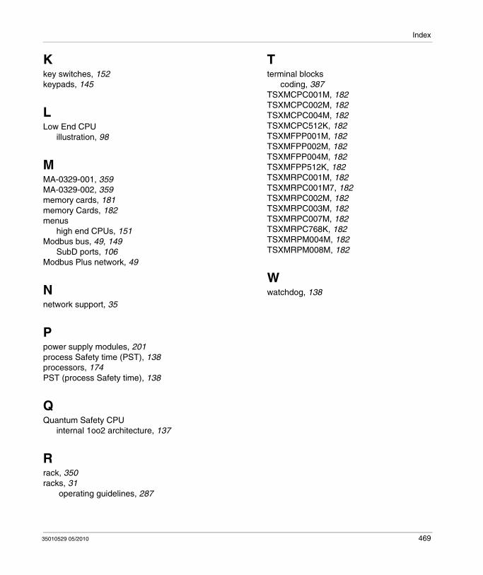
Index
Kkey switches, 152keypads, 145
LLow End CPU
illustration, 98
MMA-0329-001, 359MA-0329-002, 359memory cards, 181memory Cards, 182menus
high end CPUs, 151Modbus bus, 49, 149
SubD ports, 106Modbus Plus network, 49
Nnetwork support, 35
Ppower supply modules, 201process Safety time (PST), 138processors, 174PST (process Safety time), 138
QQuantum Safety CPU
internal 1oo2 architecture, 137
Rrack, 350racks, 31
operating guidelines, 287
35010529 05/2010
Tterminal blocks
coding, 387TSXMCPC001M, 182TSXMCPC002M, 182TSXMCPC004M, 182TSXMCPC512K, 182TSXMFPP001M, 182TSXMFPP002M, 182TSXMFPP004M, 182TSXMFPP512K, 182TSXMRPC001M, 182TSXMRPC001M7, 182TSXMRPC002M, 182TSXMRPC003M, 182TSXMRPC007M, 182TSXMRPC768K, 182TSXMRPM004M, 182TSXMRPM008M, 182
Wwatchdog, 138
469
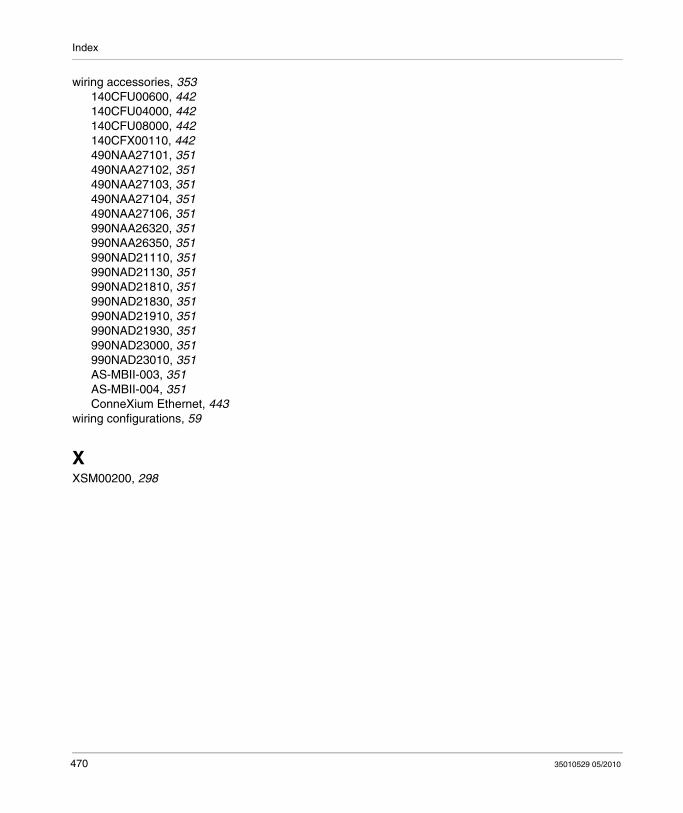
Index
wiring accessories, 353140CFU00600, 442140CFU04000, 442140CFU08000, 442140CFX00110, 442490NAA27101, 351490NAA27102, 351490NAA27103, 351490NAA27104, 351490NAA27106, 351990NAA26320, 351990NAA26350, 351990NAD21110, 351990NAD21130, 351990NAD21810, 351990NAD21830, 351990NAD21910, 351990NAD21930, 351990NAD23000, 351990NAD23010, 351AS-MBII-003, 351AS-MBII-004, 351ConneXium Ethernet, 443
wiring configurations, 59
XXSM00200, 298
470
35010529 05/2010


