

ME
AS
UR
EM
EN
T G
EN
ER
AL
CA
TA
LO
G
Laser Displacement Sensors | 2D/3D Laser Displacement Sensors | Spectral-Interference Laser Displacement Meters |
Laser Confocal Displacement Meters | Optical Micrometers | Laser Scan Micrometers | 2D Measurement Sensors |
Image Dimension Measurement Systems
High Precision MeasurementGeneral Catalog
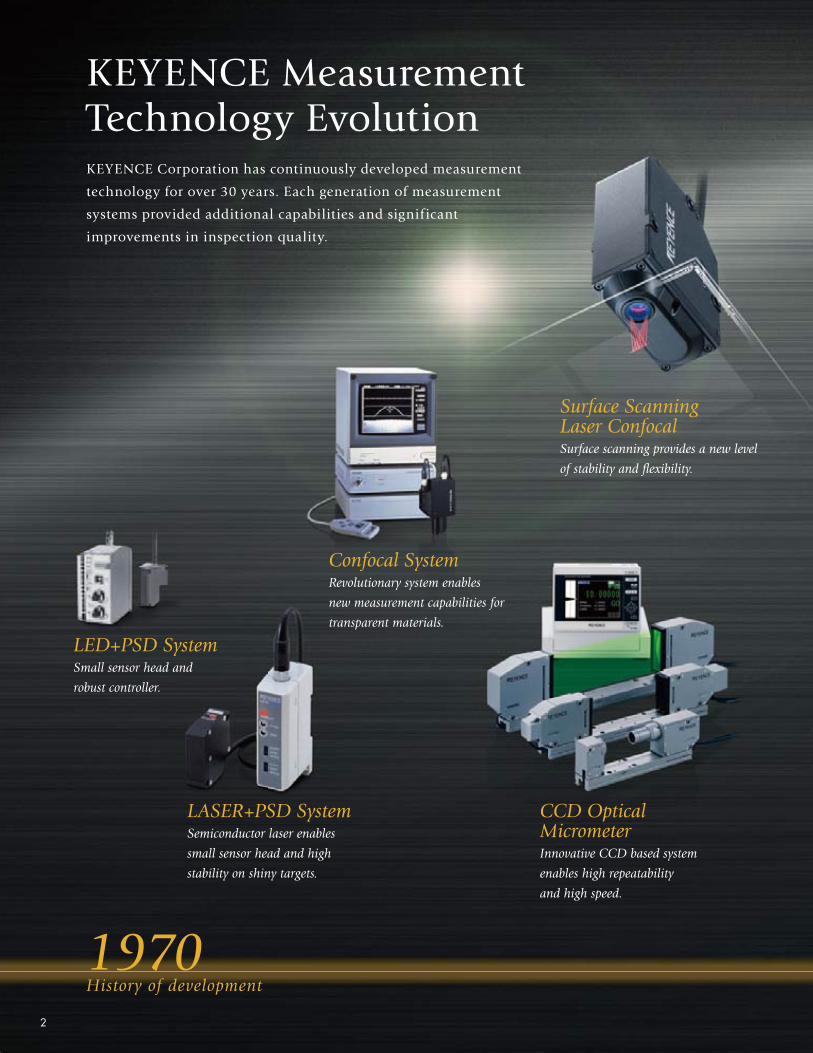
KEYENCE Measurement Technology EvolutionKEYENCE Corporation has continuously developed measurement
technology for over 30 years. Each generation of measurement
systems provided additional capabilities and significant
improvements in inspection quality.
LED+PSD System Small sensor head and
robust controller.
1970History of development
LASER+PSD SystemSemiconductor laser enables
small sensor head and high
stability on shiny targets.
Surface Scanning Laser Confocal Surface scanning provides a new level
of stability and fl exibility.
CCD Optical MicrometerInnovative CCD based system
enables high repeatability
and high speed.
Confocal SystemRevolutionary system enables
new measurement capabilities for
transparent materials.
2
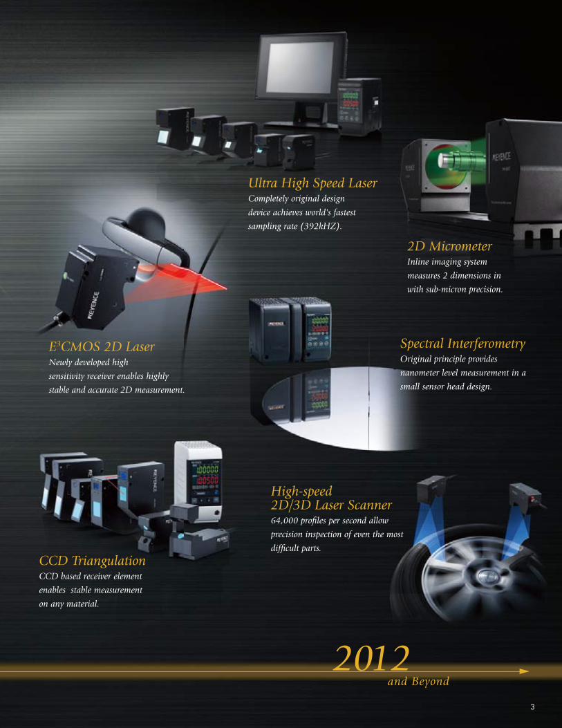
2012 and Beyond
CCD TriangulationCCD based receiver element
enables stable measurement
on any material.
E3CMOS 2D LaserNewly developed high
sensitivity receiver enables highly
stable and accurate 2D measurement.
Ultra High Speed LaserCompletely original design
device achieves world's fastest
sampling rate (392kHZ).
2D Micrometer Inline imaging system
measures 2 dimensions in
with sub-micron precision.
Spectral InterferometryOriginal principle provides
nanometer level measurement in a
small sensor head design.
High-speed2D/3D Laser Scanner64,000 profi les per second allow
precision inspection of even the most
diffi cult parts.
3
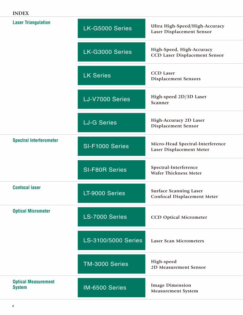
INDEX
Laser Triangulation
Spectral Interferometer
Confocal laser
Optical Micrometer
Optical Measurement System
LK-G3000 Series
Ultra High-Speed/High-Accuracy Laser Displacement Sensor
High-Speed, High-Accuracy CCD Laser Displacement Sensor
CCD LaserDisplacement Sensors
High-speed 2D/3D Laser Scanner
High-Accuracy 2D Laser Displacement Sensor
Micro-Head Spectral-InterferenceLaser Displacement Meter
Spectral-InterferenceWafer Thickness Meter
Surface Scanning Laser Confocal Displacement Meter
CCD Optical Micrometer
Laser Scan Micrometers
High-speed 2D Measurement Sensor
Image Dimension Measurement System
LK-G5000 Series
LK Series
LJ-V7000 Series
LJ-G Series
SI-F1000 Series
SI-F80R Series
LT-9000 Series
LS-7000 Series
LS-3100/5000 Series
TM-3000 Series
IM-6500 Series
4

▶
▶
▶
▶
▶
▶
▶
▶
▶
▶
▶
▶
P.10
P.18
P.24
P.26
P.34
P.40
P.46
P.48
P.52
P.58
P.62
P.68
III
Fastest in the World 392 kHzBest linearity in its Class 0.02% of F.S.Connect up to 12 sensor heads/network capable
Sampling rate of 50 kHzLinearity of 0.05% of F.S.Repeatability down to 0.01 μm 0.0004 MilCan measure diffuse, specular, transparent or translucent targetsWide beam spot models are available
IIIII
Linearity of 0.1% of F.S.Repeatability of 1 μm 0.04 Mil30 μm 1.18 Mil diameter beam spot Ultra long measuring distance up to 750 mm 29.53"Measurement unaffected by color, surface texture or stray light
IIIII
Linearity of 0.1% of F.S.High-speed samplingSimultaneous measurement/judgement of up to 8 featuresStable measurement for all targets
An emphasis on inline measurementThe world's fastest at 64,000 profi les/sec.Blue laser optical system
III
IIII
III
Resolution of 0.001 μm 0.00004 MilMicro-head size of ø2 mm ø0.08"Spectral interference method
Resolution of 0.001 μm 0.00004 MilSampling speed of 5 kHzWorking distance 80mm 3.15"
II
III
Precise 2 μm 0.08 Mil diameter beam spot0.01 μm 0.0004 Mil resolution
High repeatability 0.06 μm 0.002 MilHigh speed 2400 samples/secondMaintenance-free design
IIII
III
Repeatability of 0.3 μm 0.01 MilWide measuring rangeTouch-screen controllerUp to four heads are connectable to one controller
Multi-point 2D measurement Tilt correction for inline measurementHigh-speed sampling of 5.5 ms
III
IIII
A wide variety of measurement & auxiliary toolsCutting edge sub-pixel processing algorithmSimultaneous inspection of up to 99 featuresRevolutionary iPASS target position correction function
5
LK-G5000 SeriesLK-G3000 Series
LJ-G SeriesSI-F1000 Series
SI-F80R SeriesLS-7000 Series
LS-3100/5000 SeriesTM
-3000 SeriesIM
-6500 SeriesLK Series
LJ-V7000 SeriesLT-9000 Series
Ernostar lens
At the reference distance At a short distance At a long distance
Transmitter lens
Transmitter lens
Transmitter lens
Semiconductor laser
Semiconductor laser
Semiconductor laser
Ernostar lens
Ernostar lens
Light-receiving element
Light-receiving element
Light-receiving element
Light-receiving element
Light-receiving element
Light-receiving element
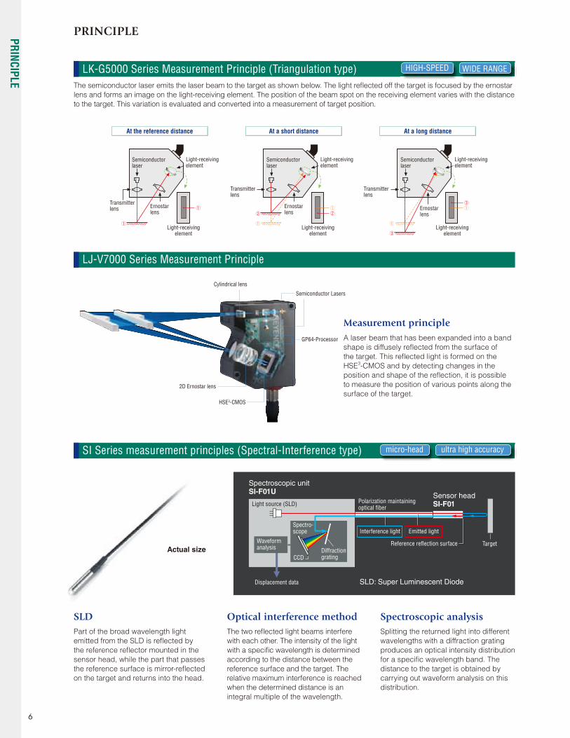
The semiconductor laser emits the laser beam to the target as shown below. The light refl ected off the target is focused by the ernostar
lens and forms an image on the light-receiving element. The position of the beam spot on the receiving element varies with the distance
to the target. This variation is evaluated and converted into a measurement of target position.
Spectroscopic analysisSplitting the returned light into different
wavelengths with a diffraction grating
produces an optical intensity distribution
for a specifi c wavelength band. The
distance to the target is obtained by
carrying out waveform analysis on this
distribution.
Optical interference methodThe two refl ected light beams interfere
with each other. The intensity of the light
with a specifi c wavelength is determined
according to the distance between the
reference surface and the target. The
relative maximum interference is reached
when the determined distance is an
integral multiple of the wavelength.
SLDPart of the broad wavelength light
emitted from the SLD is refl ected by
the reference refl ector mounted in the
sensor head, while the part that passes
the reference surface is mirror-refl ected
on the target and returns into the head.
micro-head
HIGH-SPEED
ultra high accuracy
WIDE RANGE
SI Series measurement principles (Spectral-Interference type)
LK-G5000 Series Measurement Principle (Triangulation type)
Spectroscopic unitSI-F01U
Actual size
SLD: Super Luminescent Diode
Sensor headSI-F01Polarization maintaining
optical fi berLight source (SLD)
Reference refl ection surface
Displacement data
Diffractiongrating
Waveformanalysis
Spectro-scope
CCD
Target
Interference light Emitted light
LJ-V7000 Series Measurement Principle
2D Ernostar lens
HSE3-CMOS
Cylindrical lens
Semiconductor Lasers
GP64-Processor
Measurement principle A laser beam that has been expanded into a band
shape is diffusely refl ected from the surface of
the target. This refl ected light is formed on the
HSE3-CMOS and by detecting changes in the
position and shape of the refl ection, it is possible
to measure the position of various points along the
surface of the target.
PRINCIPLE
6
PRINCIPLE
Mirror
Lens
Diffusion unit
Telecentric lens Collimator lens
Receiver TransmitterLEDCMOS
TargetLens
Mirror
The received light intensity is low.
The received light intensity is low.
Semiconductor laser
Semiconductor laser
Light-receiving element
Light-receiving element
Pinhole Pinhole
Sensor Sensor
Tuning fork Tuning fork
A small amount of received light passes through the pinhole.
All of the received light passes through the pinhole.
When the focal point is not on the target surface When the focal point is on the target surface
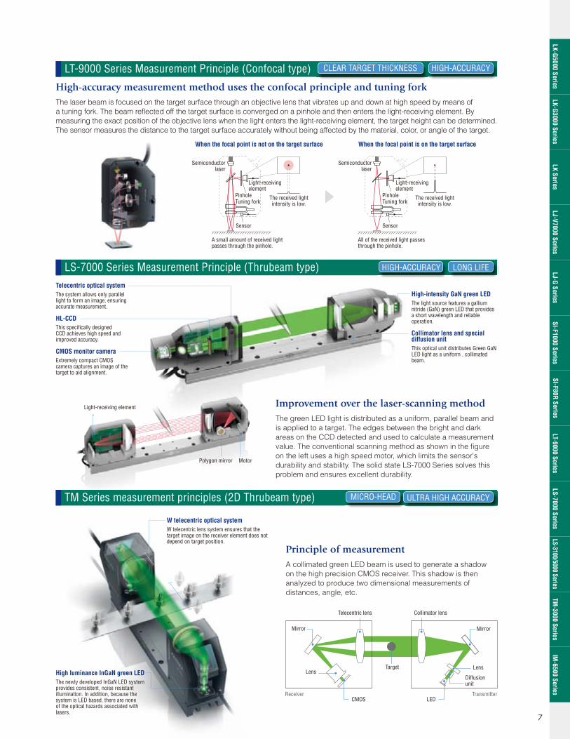
Telecentric optical systemThe system allows only parallel light to form an image, ensuring accurate measurement.
HL-CCDThis specifi cally designed CCD achieves high speed and improved accuracy.
CMOS monitor cameraExtremely compact CMOS camera captures an image of the target to aid alignment.
High luminance InGaN green LEDThe newly developed InGaN LED system provides consistent, noise resistant illumination. In addition, because the system is LED based, there are none of the optical hazards associated with lasers.
W telecentric optical systemW telecentric lens system ensures that the target image on the receiver element does not depend on target position.
High-intensity GaN green LEDThe light source features a gallium nitride (GaN) green LED that provides a short wavelength and reliable operation.
Collimator lens and special diffusion unitThis optical unit distributes Green GaN LED light as a uniform , collimated beam.
Light-receiving element
Polygon mirror Motor
High-accuracy measurement method uses the confocal principle and tuning forkThe laser beam is focused on the target surface through an objective lens that vibrates up and down at high speed by means of
a tuning fork. The beam refl ected off the target surface is converged on a pinhole and then enters the light-receiving element. By
measuring the exact position of the objective lens when the light enters the light-receiving element, the target height can be determined.
The sensor measures the distance to the target surface accurately without being affected by the material, color, or angle of the target.
Improvement over the laser-scanning method The green LED light is distributed as a uniform, parallel beam and
is applied to a target. The edges between the bright and dark
areas on the CCD detected and used to calculate a measurement
value. The conventional scanning method as shown in the fi gure
on the left uses a high speed motor, which limits the sensor's
durability and stability. The solid state LS-7000 Series solves this
problem and ensures excellent durability.
Principle of measurementA collimated green LED beam is used to generate a shadow
on the high precision CMOS receiver. This shadow is then
analyzed to produce two dimensional measurements of
distances, angle, etc.
CLEAR TARGET THICKNESS HIGH-ACCURACY
HIGH-ACCURACY
MICRO-HEAD
LONG LIFE
ULTRA HIGH ACCURACY
LT-9000 Series Measurement Principle (Confocal type)
LS-7000 Series Measurement Principle (Thrubeam type)
TM Series measurement principles (2D Thrubeam type)
7
LK-G5000 SeriesLK-G3000 Series
LJ-G SeriesSI-F1000 Series
SI-F80R SeriesLS-7000 Series
LS-3100/5000 SeriesTM
-3000 SeriesIM
-6500 SeriesLK Series
LJ-V7000 SeriesLT-9000 Series
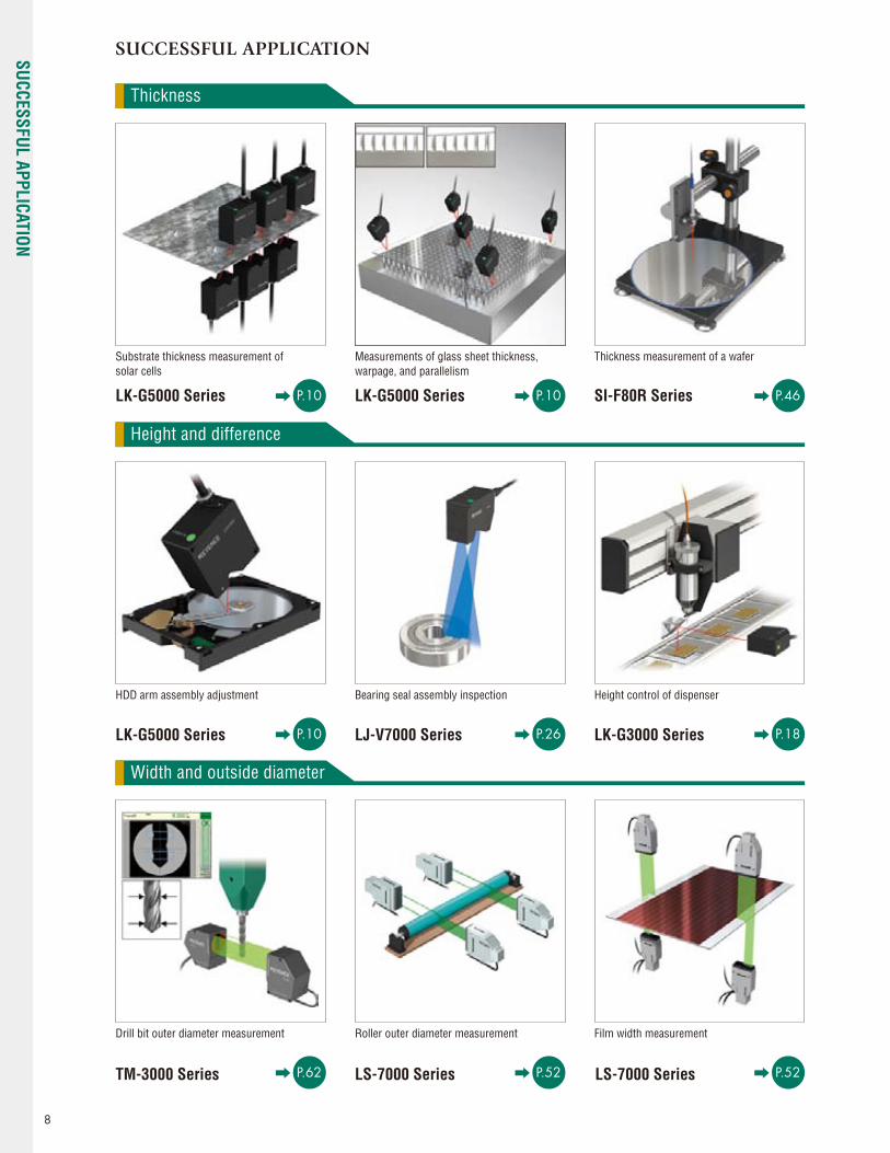
SUCCESSFUL APPLICATION
Substrate thickness measurement of solar cells
LK-G5000 Series
LK-G5000 Series
TM-3000 Series LS-7000 Series LS-7000 Series
LJ-V7000 Series LK-G3000 Series
LK-G5000 Series
HDD arm assembly adjustment
Drill bit outer diameter measurement
Height control of dispenser
Film width measurement
Measurements of glass sheet thickness, warpage, and parallelism
Bearing seal assembly inspection
Roller outer diameter measurement
Thickness
Height and difference
Width and outside diameter
P.18
P.52
P.10
P.26
P.52
P.10
P.10
P.62
SI-F80R Series
Thickness measurement of a wafer
P.46
8
SUCCESSFUL APPLICATION

Ultrasonic welder monitoring
Swinging and vibration
Stroke and positioning
Shape and warp
LK-G5000 Series
SI Series
LK-G5000 Series
LJ-V7000 Series
TM-3000 Series LJ-V7000 Series
LK-G3000 Series
LK-G5000 Series LK-G5000 Series
Precision stage positioning
Warpage measurement of a circuit board
Disk rotor warpage measurement
Position tracking of high temperature steel pipe
Tire side-wall shape inspection
Pre-weld assembly check
Ampoule shape inspection
Tire runout measurement
P.10
P.18
P.26
P.10
P.26
P.62
P.10
P.40
P.10
9
LK-G5000 SeriesLK-G3000 Series
LJ-G SeriesSI-F1000 Series
SI-F80R SeriesLS-7000 Series
LS-3100/5000 SeriesTM
-3000 SeriesIM
-6500 SeriesLK Series
LJ-V7000 SeriesLT-9000 Series
2x wider than conventional model
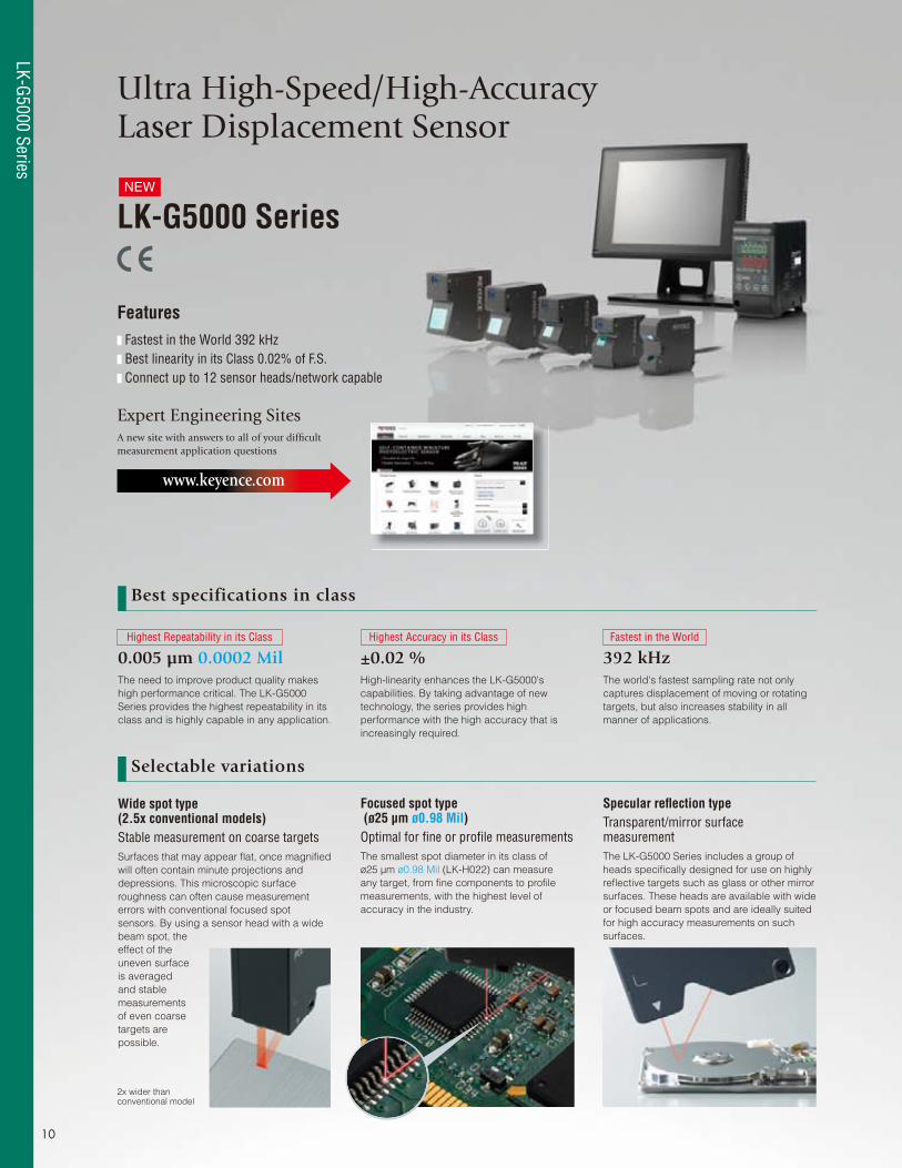
Ultra High-Speed/High-AccuracyLaser Displacement Sensor
0.005 μm 0.0002 Mil ±0.02 % 392 kHzThe need to improve product quality makes
high performance critical. The LK-G5000
Series provides the highest repeatability in its
class and is highly capable in any application.
High-linearity enhances the LK-G5000's
capabilities. By taking advantage of new
technology, the series provides high
performance with the high accuracy that is
increasingly required.
The world's fastest sampling rate not only
captures displacement of moving or rotating
targets, but also increases stability in all
manner of applications.
Highest Repeatability in its Class Highest Accuracy in its Class Fastest in the World
Focused spot type (ø25 µm ø0.98 Mil)Optimal for fi ne or profi le measurementsThe smallest spot diameter in its class of
ø25 μm ø0.98 Mil (LK-H022) can measure
any target, from fi ne components to profi le
measurements, with the highest level of
accuracy in the industry.
Specular refl ection typeTransparent/mirror surface measurementThe LK-G5000 Series includes a group of
heads specifi cally designed for use on highly
refl ective targets such as glass or other mirror
surfaces. These heads are available with wide
or focused beam spots and are ideally suited
for high accuracy measurements on such
surfaces.
Wide spot type(2.5x conventional models)Stable measurement on coarse targetsSurfaces that may appear fl at, once magnifi ed
will often contain minute projections and
depressions. This microscopic surface
roughness can often cause measurement
errors with conventional focused spot
sensors. By using a sensor head with a wide
beam spot, the
effect of the
uneven surface
is averaged
and stable
measurements
of even coarse
targets are
possible.
LK-G5000 Series
Features Fastest in the World 392 kHz Best linearity in its Class 0.02% of F.S. Connect up to 12 sensor heads/network capable
Expert Engineering SitesA new site with answers to all of your diffi cult measurement application questions
www.keyence.com
NEW
Selectable variations
Best specifications in class
10
LK-G5000 Series

LK-G5000 Series
Applications
Lineup
Active layer measurement of solar modules Measurements of glass board thickness, warpage, and parallelism
Position control of an air knife
Sensor Head
Measurement type Reference Distance & Measurement Range Repeatability Model
WIDE SPOT TYPE
8±0.5 mm 0.32" ± 0.02" 0.005 μm 0.0002 Mil LK-H008W
20±3 mm 0.79" ± 0.12" 0.02 μm 0.0008 Mil LK-H027
50±10 mm 1.97" ± 0.39" 0.025 μm 0.001 Mil LK-H057
80±18 mm 3.15" ± 0.71" 0.1 μm 0.004 Mil LK-H087
150±40 mm 5.91" ± 1.57" 0.25 μm 0.01 Mil LK-H157
FOCUSED SPOT TYPE
8±0.5 mm 0.32" ± 0.02" 0.005 μm 0.0002 Mil LK-H008
20±3 mm 0.79" ± 0.12" 0.02 μm 0.0008 Mil LK-H022
50±10 mm 1.97" ± 0.39" 0.025 μm 0.001 Mil LK-H052
80±18 mm 3.15" ± 0.71" 0.1 μm 0.004 Mil LK-H082
150±40 mm 5.91" ± 1.57" 0.25 μm 0.001 Mil LK-H152
SPECULAR REFLECTION TYPE
8±0.5 mm 0.32" ± 0.02" 0.005 μm 0.0002 Mil LK-H008(W)
16.1±2.8 mm 0.63" ± 0.11" 0.02 μm 0.0008 Mil LK-H027K
46.3±5.2 mm 1.82" ± 0.20" 0.025 μm 0.001 Mil LK-H057K
76.7 -17.6 mm/+14.5 mm 3.02" -0.69"/+0.57" 0.1 μm 0.004 Mil LK-H087 & LK-F3
147.5 -39.5 mm /+24.4 mm 5.81" -1.56"/+0.96" 0.25 μm 0.01 Mil LK-H157 & LK-F2
Main controller
All-in-one typeLK-G5001(P)V
Separate display typeLK-G5001(P)
Additional head unitLK-HA100
CC-Link unitLK-CC100
DeviceNet unitLK-DN100
Display
Touch panel displayLK-HD1001
Compact displayLK-HD500
Confi guration Software
Cable Neutral density fi lter
LK-Navigator2LK-H2
Sensor head-to-controller cable(0.7, 2, 5, 10, 20, 30 m)(2.30', 6.56', 16.4', 32.81',65.62', 98.43')CB-Axx
For LK-H08x
LK-F3
For LK-H15x
LK-F2
Extension cable between the head and cable(5, 10 m)(16.4', 32.81')CB-AxxE
Controller-to-displayconnection cable0.33 m 1.08' : OP-84427
3 m 9.84': OP-51655
10 m 32.81': OP-51656
I/O Cable and ConnectorOP-51657
Ethernet cableOP-66843
11
LK-G5000 SeriesLK-G3000 Series
LJ-G SeriesSI-F1000 Series
SI-F80R SeriesLS-7000 Series
LS-3100/5000 SeriesTM
-3000 SeriesIM
-6500 SeriesLK Series
LJ-V7000 SeriesLT-9000 Series

A D
CBA
D
B
E
C
F
A
B
C
A B
C
A
B
C A
B
C
Calculates the differences between a referencepoint and each measuring point.
Calculates theamount of warpage.
Calculates the maximum and/or minimum values.
Calculates thethickness with eachpair of sensors.
Calculates the difference between the maximum and minimum values among the measurement points.
Calculates theaverage height.
Convenient calculation functions
Instantly calculates values based on measurements obtained by more than one head, enabling the user to easily set complicated calculations inside
the controller that were conventionally done with PLCs or PCs.
Measured value1=B-A Measured value2=B-CMeasured value3=A-C…
Measured value1=B-(A+C)/2…
Measured value1=MAX (A,B,C...)−MIN (A,B,C...)...
Measured value1=Ave (A,B,C,D,...)
Measured value1=MAX (A,B,C...)Measured value2=MIN (A,B,C...)
Measured value1=X+ (A+D) Measured value2=Y+ (B+E)Measured value3=Z+ (C+F)...
Standard Step Measurement
Warpage Measurement
Maximum/Minimum Measurement
Multi-Point Thickness Measurement
Flatness Measurement
Average Height Measurement
Measurement of Velocity (m/s), Acceleration (m/s2)
The LK-G5000 Series is equipped with a function to directly measure the speed (m/s)
and acceleration (m/s2) of targets. Just select the type of measurement: displacement,
speed, or acceleration. Using the differential processing circuit is inside the controller, it
is possible to directly output or evaluate measurements that were previously calculated
externally. The LK-G5000 Series is suitable for lightweight, easily deformed, and high-
temperature targets which are diffi cult to measure with contact accelerometers.
Data filter functions made easy
Wave pattern when using the median fi lter
Wave pattern when using the average fi lter
Unfi ltered wave pattern
Unfi ltered wave pattern Wave pattern when using the high pass fi lter
Unfi ltered wave pattern
Unfi ltered wave pattern Wave pattern when using the low pass fi lter
4 types of easy to use data processing fi lters are incorporated directly in the controller. The fi lters are user selectable for ease of use.
AccelerationSpeedDisplacement Vibration test of high-temperature-muffler
Averages the measured values to reduce high the overall noise level in the mea-surement.
Removes any intermittent noise in the output. Captures sudden changes and removes low frequency variations.
Moving average fi lter
Median fi lter High pass fi lter
Captures moderate changes while removing high frequency noise.Low pass fi lter
Example of measurement of stage movement
12
LK-G5000 Series

LK-G5000 Series
Specifi cations
Controller
Main unit/head expansion unit
ModelSingle unit type LK-G5001V LK-G5001PV
LK-HA100Separate type LK-G5001/LK-HD500 LK-G5001P/LK-HD500
Designation Main controller Head expansion unit
Sensor head compatibility Compatible
No. of connectable sensor heads 2 1
Display(LK-HD500)
Minimum display unit 0.001 μm 0.0001 Mil
N/ADisplay range ±999.999 μm to ±9999.99 mm ±9.99999 Mil to ±99.9999" (7 settings selectable)
Display cycle Approx. 10 times/sec.
Display interface
Display port Either the display unit (LK-HD500) or dedicated touch panel (LK-HD1001) can be connected
N/A
LED indicator LASER ON POWER ON, STABILITY, BRIGHT, DARK
Terminal block
Analog voltage output ±10 V output, Output impedance: 100 Ω
Analog current output 4 to 20 mA, Maximum load resistance: 350 Ω
No. of analog outputs 2 1
TIMING1 input*1 Non-voltage input Voltage input
N/A
RESET1 input*1
Non-voltage input Voltage inputAuto-zero1 input*1
Laser control input*2
Laser remote input Non-voltage input
Alarm outputNPN open-collector output PNP open-collector output
General comparator output
Expansion connector
TIMING input Non-voltage input Voltage input
N/A
RESET input
Non-voltage input Voltage inputAuto-zero input
Program switch input
Binary selection input
Alarm output
NPN open-collector output PNP open-collector outputComparator output
Binary output
RS-232C interface Baud rate: 9600 to 115200 bpsData length: 8 bits Stop bit length: 1 bit Parity: None/even/odd
N/AUSB interface USB 2.0 Hi-Speed compliant*3
Ethernet interface*4 100Base-TX/10Base-T
Head expansion unit connector Up to 10 head expansion units can be connected to one main controller
Expansion unit connector Either of the CC-Link unit (LK-CC100) or DeviceNet unit (LK-DN100) can be connected N/A
Power supplyPower supply voltage 24 VDC±10% 24 VDC±10% (Supplied from the controller)
Maximum current consumption 0.6 A or less with 1 head/3.5 A or less with 12 heads
Environment resistance
Ambient temperature When one or less head expansion unit is connected: 0 to 50°C 32 to 122˚FWhen two or more head expansion units are connected: 0 to 40°C 32 to 104˚F
Relative humidity 35 to 85%RH (No condensation)
Weight Approx. 600 g Approx. 300 g
*1 This input is applied to all of the synchronized OUT.*2 When the laser class 3B sensor head is connected, a key-operated switch must be used for the input to this terminal. The laser is emitted only when the key-operated switch is set to the ON position.
(Select a key which can be removed only when it is set to the OFF position.) When the laser class 2/3R sensor head is connected, the laser turns on when this terminal is opened and turns off when it is short-circuited.*3 When a PC supporting USB 1.1 or USB 2.0 full speed is connected, the data refresh cycle and other operations may slow down.*4 Use the Ethernet interface only for direct connections with a PC or for local network connections with a PC or LK-G5000 Series units.• NPN open-collector output rating: 50 mA max. (40 V max.), Residual voltage: 0.5 V max.• PNP open-collector output rating: 50 mA max. (30 V max.), Residual voltage: 0.5 V max.• Non-voltage input rating: ON voltage: 1 V max., OFF current: 0.6 mA max.• Voltage input rating: Maximum input rating: 26.4 V, ON voltage: 10.2 V, OFF current: 0.6 mA• Part of the input/output circuit of the LK-G5000 Series is internally common. Be careful that no potential difference is generated between the internally common terminals due to the potential difference between the cables/external devices.
For details, refer to "Precautions on wiring" in the User's Manual.
LK-H2 (LK-Navigator2) Operating environment
CPU Pentium III 1 GHz or higher (1.7 GHz or higher recommended)
Supported OS Windows 7*1 Windows Vista*2 Windows XP*3 Windows 2000 Professional*4
Memory capacity 256 MB or more (1 GB or more recommended)
Display resolution 1024 x 768 pixels, 24-bit full color or better
Available hard disk space 1 GB or more
InterfaceThe PC must be equipped with one of these interfaces: • USB: 2.0 Hi-Speed (USB 1.1 compatible full speed)*5
• LAN: 100BASE-TX, 10BASE-T*6
*1 Editions supported: Ultimate, Professional and Home Premium.*2 Editions supported: Ultimate, Business, Home Premium, and Home Basic.*3 Supports Professional SP2 and Home Edition SP2 or later.*4 Supports SP4 or later.*5 Does not support connection via a USB hub.*6 Does not support connection via private LANs or routers. Use in a 1:1 or local connection.* Windows is a registered trademark of Microsoft Corporation of America.* Pentium is a registered trademark of Intel Corporation.
13
LK-G5000 SeriesLK-G3000 Series
LJ-G SeriesSI-F1000 Series
SI-F80R SeriesLS-7000 Series
LS-3100/5000 SeriesTM
-3000 SeriesIM
-6500 SeriesLK Series
LJ-V7000 SeriesLT-9000 Series

Sensor heads
Coarse target measurement (wide spot type)
Model LK-H008W LK-H025 LK-H027 LK-H055 LK-H057 LK-H085 LK-H087 LK-H155 LK-H157
Mounting mode Specular refl ection Diffuse refl ection Diffuse refl ection Diffuse refl ection Diffuse refl ection Diffuse refl ection Diffuse refl ection Diffuse refl ection Diffuse refl ection
Reference distance 8 mm 0.32" 20 mm 0.79" 20 mm 0.79" 50 mm 1.97" 50 mm 1.97" 80 mm 3.15" 80 mm 3.15" 150 mm 5.91" 150 mm 5.91"
Measurement range*1 ±0.5 mm ±0.02" ±3 mm ±0.12" ±3 mm ±0.12" ±10 mm ±0.39" ±10 mm ±0.39" ±18 mm ±0.71" ±18 mm ±0.71" ±40 mm ±1.57" ±40 mm ±1.57"
Ligh
t sou
rce
Red semiconductor laser
Wavelength 655 nm
Laser class
IEC 60825-1 Class 1 Class 3R Class 2 Class 3R Class 2 Class 3R Class 2 Class 3R Class 2
FDA (CDRH) Part 1040.10 Class II Class IIIa Class II Class IIIa Class II Class IIIa Class II Class IIIa Class II
Output 0.3 mW 4.8 mW 0.95 mW 4.8 mW 0.95 mW 4.8 mW 0.95 mW 4.8 mW 0.95 mW
Spot diameter (at reference distance) 20 μm × 550 μm 25 μm × 1400 μm 50 μm × 2000 μm 70 μm × 2500 μm 120 μm × 4200 μm
Linearity*2 ±0.05% of F.S.(F.S.=1 mm 0.04")
±0.02%of F.S.(F.S.= 6 mm 0.24")
±0.02% of F.S.(F.S.= 20 mm 0.79")
±0.02% of F.S.(F.S.= 36 mm 1.42")
±0.02% of F.S.(F.S.= 80 mm 3.15")
Repeatability*3 0.005 μm (0.001 μm) 0.02 μm (0.01 μm) 0.025 μm 0.1 μm 0.25 μm
Sampling cycle 2.55/5/10/20/50/100/200/500/1000 μs (9 steps selectable)
Temperature fl uctuation 0.02% of F.S./°C (F.S.=1 mm 0.04")
0.01% of F.S./°C(F.S.= 6 mm 0.24")
0.01% of F.S./°C (F.S.= 20 mm 0.79")
0.01% of F.S./°C(F.S.= 36 mm 1.42")
0.01% of F.S./°C(F.S.= 80 mm 3.15")
Envir
onm
ent r
esist
ance Enclosure rating IP67
Ambient light Incandescent lamp or fl uorescent lamp: 10000 lux max.Incandescent lamp
or fl uorescent lamp: 5000 lux max.
Ambient temperature 0 to +50°C 32 to 122˚F *4 0 to +50°C 32 to 122˚F 0 to +50°C 32 to 122˚F*4
Relative humidity 35 to 85%RH (No condensation)
Vibration resistance 10 to 55 Hz, 1.5 mm 0.06" double amplitude in X, Y, and Z directions, 2 hours respectively
Material Aluminum die-cast
Weight Approx. 240 g Approx. 230 g Approx. 260 g Approx. 280 g Approx. 300 g*1 Measurement range when the sampling cycle is 20 μs or more. *2 This value is obtained when the KEYENCE standard target (White diffuse workpiece or workpiece with a metal mirror surface only for the LK-H008W) is measured in the normal measurement mode. *3 This value is obtained when the KEYENCE standard target (White diffuse workpiece or workpiece with a metal mirror surface only for the LK-H008W) is measured at the reference distance with the number of averaging measurements set to 16384. The value in parentheses is a typical example of a measurement with the number of averaging measurements set to 65536 and the sampling cycle to 200 μs. *4 When the ambient temperature rises to 40°C 104°F or more, mount this on a metal plate before use.
Fine target measurement (focused spot type)
Model LK-H008 LK-H020 LK-H022 LK-H050 LK-H052 LK-H080 LK-H082 LK-H150 LK-H152
Mounting mode Specular refl ection Diffuse refl ection Diffuse refl ection Diffuse refl ection Diffuse refl ection Diffuse refl ection Diffuse refl ection Diffuse refl ection Diffuse refl ectionReference distance 8 mm 0.32" 20 mm 0.79" 20 mm 0.79" 50 mm 1.97" 50 mm 1.97" 80 mm 3.15" 80 mm 3.15" 150 mm 5.91" 150 mm 5.91"Measurement range*1 ±0.5 mm ±0.02" ±3 mm ±0.12" ±3 mm ±0.12" ±10 mm ±0.39" ±10 mm ±0.39" ±18 mm ±0.71" ±18 mm ±0.71" ±40 mm ±1.57" ±40 mm ±1.57"
Ligh
t sou
rce Red semiconductor laser
Wavelength 655 nm
Laser class
IEC 60825-1 Class 1 Class 3R Class 2 Class 3R Class 2 Class 3R Class 2 Class 3R Class 2FDA (CDRH) Part 1040.10 Class II Class IIIa Class II Class IIIa Class II Class IIIa Class II Class IIIa Class II
Output 0.3 mW 4.8 mW 0.95 mW 4.8 mW 0.95 mW 4.8 mW 0.95 mW 4.8 mW 0.95 mWSpot diameter (at reference distance) ø20 μm ø25 μm ø50 μm ø70 μm ø120 μm
Linearity*2 ±0.05% of F.S.(F.S.=1 mm 0.04")
±0.02% of F.S.(F.S.= 6 mm 0.24")
±0.02% of F.S.(F.S.= 20 mm 0.79")
±0.02% of F.S.(F.S.= 36 mm 1.42")
±0.02% of F.S.(F.S.= 80 mm 3.15")
Repeatability*3 0.005 μm (0.001 μm) 0.02 μm (0.01 μm) 0.025 μm 0.1 μm 0.25 μmSampling cycle 2.55/5/10/20/50/100/200/500/1000 μs (9 steps selectable)
Temperature fl uctuation 0.02% of F.S./°C(F.S.=1 mm 0.04")
0.01% of F.S./°C(F.S.= 6 mm 0.24")
0.01% of F.S./°C(F.S.= 20 mm 0.79")
0.01% of F.S./°C(F.S.= 36 mm 1.42")
0.01% of F.S./°C(F.S.= 80 mm 3.15")
Envir
onm
ent r
esist
ance Enclosure rating IP67
Ambient light Incandescent lamp or fl uorescent lamp: 10000 lux max.Incandescent lamp
or fl uorescent lamp: 5000 lux max.
Ambient temperature 0 to +50°C 32 to 122˚F *4 0 to +50°C 32 to 122˚F 0 to +50°C 32 to 122˚F*4
Relative humidity 35 to 85%RH (No condensation)Vibration resistance 10 to 55 Hz, 1.5 mm 0.06" double amplitude in X, Y, and Z directions, 2 hours respectively
Material Aluminum die-castWeight Approx. 240 g Approx. 230 g Approx. 260 g Approx. 280 g Approx. 300 g
*1 Measurement range when the sampling cycle is 20 μs or more. *2 This value is obtained when the KEYENCE standard target (White diffuse workpiece or workpiece with a metal mirror surface only for the LK-H008) is measured in the normal measurement mode. *3 This value is obtained when the KEYENCE standard target (White diffuse workpiece or workpiece with a metal mirror surface only for the LK-H008) is measured at the reference distance with the number of averaging measurements set to 16384. The value in parentheses is a typical example of a measurement with the number of averaging measurements set to 65536 and the sampling cycle to 200 μs. *4 When the ambient temperature rises to 40°C 104°F or more, mount this on a metal plate before use.
Transparent/mirror target measurement (specular refl ection type)
Model LK-H008 LK-H008W LK-H022K LK-H027K LK-H052K LK-H057K LK-H082 LK-H087 LK-H152 LK-H157
Mounting mode Specular refl ection Specular refl ection Specular refl ection Specular refl ection Specular refl ection Specular refl ection Specular refl ection*4 Specular refl ection*4
Reference distance 8 mm 0.32" 8 mm 0.32" 16.1 mm 0.63" 16.1 mm 0.63" 46.3 mm 1.82" 46.3 mm 1.82" 76.7 mm 3.02" 147.5 mm 5.81"
Measurement range*1 ±0.5 mm ±0.02"
±0.5 mm ±0.02"
±2.8 mm ±0.11"
±2.8 mm ±0.11"
±5.2 mm ±0.20"
±5.2 mm ±0.20"
−17.6 mm to +14.5 mm -0.69" to +0.57"
−39.5 mm to +24.4 mm -1.56" to +0.96"
Ligh
t sou
rce Red semiconductor laser
Wavelength 655 nm
Laser class
IEC 60825-1 Class 1 Class 2FDA (CDRH) Part 1040.10 Class II
Output 0.3 mW 0.95 mWSpot diameter (at reference distance) ø20μm 20 μm×550 μm ø25 μm 25 μm×1400 μm ø50 μm 50 μm×2000 μm ø70 μm 70 μm × 2500 μm ø120 μm 120 μm × 4200 μmLinearity*2 ±0.05% of F.S. (F.S.= 1 mm 0.04") ±0.02% of F.S. (F.S.= 6 mm 0.24") ±0.02% of F.S. (F.S.= 20 mm 0.79") ±0.02% of F.S. (F.S.= 36 mm 1.42") ±0.02% of F.S. (F.S.= 80 mm 3.15")Repeatability*3 0.005 μm (0.001 μm) 0.02 μm (0.01 μm) 0.025 μm 0.1 μm 0.25 μmSampling cycle 2.55/5/10/20/50/100/200/500/1000 μs (9 steps selectable)Temperature fl uctuation 0.02% of F.S./°C (F.S.=1 mm 0.04") 0.01% of F.S./°C (F.S.= 6 mm 0.24") 0.01% of F.S. (F.S.= 20 mm 0.79") 0.01% of F.S. (F.S.= 36 mm 1.42")*6 0.01% of F.S. (F.S.= 80 mm 3.15")*6
Envir
onm
ent r
esist
ance Enclosure rating IP67
Ambient light Incandescent lamp or fl uorescent lamp: 10000 lux max. Incandescent lamp or fl uorescent lamp: 5000 lux max.
Ambient temperature 0 to +50°C 32 to 122˚F*5 0 to +50°C 32 to 122˚F 0 to +50°C 32 to 122˚F*5
Relative humidity 35 to 85% RH (No condensation)Vibration resistance 10 to 55 Hz, 1.5 mm 0.06" double amplitude in X, Y, and Z directions, 2 hours respectively
Material Aluminum die-castWeight Approx. 240 g Approx. 230 g Approx. 260 g Approx. 280 g Approx. 300 g
*1 Measurement range when the sampling cycle is 20 μs or more. *2 This value is obtained when the KEYENCE standard target (White diffuse workpiece or workpiece with a metal mirror surface only for the LK-H008/LK-H008W) is measured in the normal measurement mode. *3 This value is obtained when the KEYENCE standard target (White diffuse workpiece or workpiece with a metal mirror surface only for the LK-H008/LK-H008W) is measured at the reference distance with the number of averaging measurements set to 16384. The value in parentheses is a typical example of a measurement with the number of averaging measurements set to 65536 and the sampling cycle to 200 μs. *4 Use one of the following dark fi lters when measuring a transparent or mirror surface object: LK-H082/LK-H087: LK-F3, LK-H152/LK-H157: LK-F2 *5 When the ambient temperature rises to 40°C 104°F or more, mount this on a metal plate before use.*6 Value measured at the event of diffuse refl ection installation. Please contact us for the case of regular refl ection installation.14
LK-G5000 Series
LK-G5000 Series
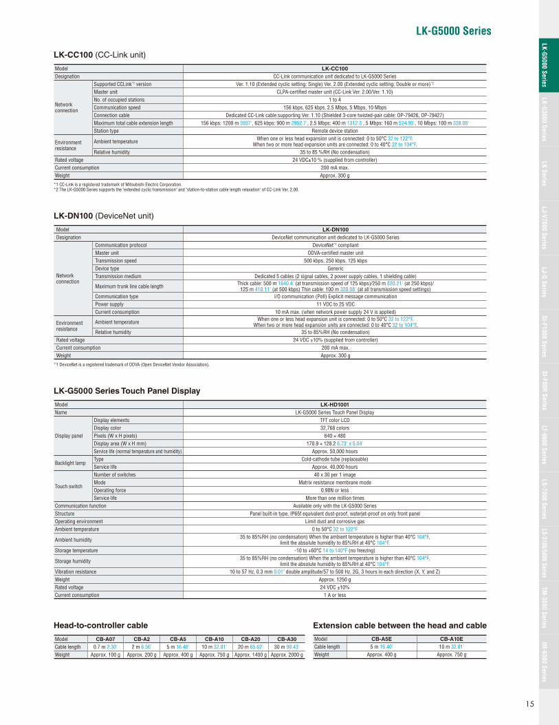
LK-CC100 (CC-Link unit)
Model LK-CC100
Designation CC-Link communication unit dedicated to LK-G5000 Series
Network connection
Supported CCLink*1 version Ver. 1.10 (Extended cyclic setting: Single) Ver. 2.00 (Extended cyclic setting: Double or more)*2
Master unit CLPA-certifi ed master unit (CC-Link Ver. 2.00/Ver. 1.10)No. of occupied stations 1 to 4Communication speed 156 kbps, 625 kbps, 2.5 Mbps, 5 Mbps, 10 MbpsConnection cable Dedicated CC-Link cable supporting Ver. 1.10 (Shielded 3-core twisted-pair cable: OP-79426, OP-79427)Maximum total cable extension length 156 kbps: 1200 m 3937', 625 kbps: 900 m 2952.7', 2.5 Mbps: 400 m 1312.3', 5 Mbps: 160 m 524.93', 10 Mbps: 100 m 328.08'Station type Remote device station
Environment resistance
Ambient temperature When one or less head expansion unit is connected: 0 to 50°C 32 to 122°F. When two or more head expansion units are connected: 0 to 40°C 32 to 104°F.
Relative humidity 35 to 85 %RH (No condensation)Rated voltage 24 VDC±10 % (supplied from controller)Current consumption 200 mA max.Weight Approx. 300 g
*1 CC-Link is a registered trademark of Mitsubishi Electric Corporation.*2 The LK-G5000 Series supports the "extended cyclic transmission" and "station-to-station cable length relaxation" of CC-Link Ver. 2.00.
LK-DN100 (DeviceNet unit)
Model LK-DN100
Designation DeviceNet communication unit dedicated to LK-G5000 Series
Network connection
Communication protocol DeviceNet*1 compliantMaster unit ODVA-certifi ed master unitTransmission speed 500 kbps, 250 kbps, 125 kbpsDevice type GenericTransmission medium Dedicated 5 cables (2 signal cables, 2 power supply cables, 1 shielding cable)
Maximum trunk line cable length Thick cable: 500 m 1640.4' (at transmission speed of 125 kbps)/250 m 820.21' (at 250 kbps)/125 m 410.11' (at 500 kbps) Thin cable: 100 m 328.08' (at all transmission speed settings)
Communication type I/O communication (Poll) Explicit message communicationPower supply 11 VDC to 25 VDCCurrent consumption 10 mA max. (when network power supply 24 V is applied)
Environment resistance
Ambient temperature When one or less head expansion unit is connected: 0 to 50°C 32 to 122°F. When two or more head expansion units are connected: 0 to 40°C 32 to 104°F.
Relative humidity 35 to 85%RH (No condensation)Rated voltage 24 VDC ±10% (supplied from controller)Current consumption 200 mA max.Weight Approx. 300 g
*1 DeviceNet is a registered trademark of ODVA (Open DeviceNet Vendor Association).
LK-G5000 Series Touch Panel Display
Model LK-HD1001
Name LK-G5000 Series Touch Panel Display
Display panel
Display elements TFT color LCDDisplay color 32,768 colorsPixels (W x H pixels) 640 × 480Display area (W x H mm) 170.9 × 128.2 6.73' x 5.04'Service life (normal temperature and humidity) Approx. 50,000 hours
Backlight lampType Cold-cathode tube (replaceable)Service life Approx. 40,000 hours
Touch switch
Number of switches 40 x 30 per 1 imageMode Matrix resistance membrane modeOperating force 0.98N or lessService life More than one million times
Communication function Available only with the LK-G5000 SeriesStructure Panel built-in type, IP65f equivalent dust-proof, waterjet-proof on only front panelOperating environment Limit dust and corrosive gasAmbient temperature 0 to 50°C 32 to 122°F
Ambient humidity 35 to 85%RH (no condensation) When the ambient temperature is higher than 40°C 104°F, limit the absolute humidity to 85%RH at 40°C 104°F.
Storage temperature -10 to +60°C 14 to 140°F (no freezing)
Storage humidity 35 to 85%RH (no condensation) When the ambient temperature is higher than 40°C 104°F, limit the absolute humidity to 85%RH at 40°C 104°F.
Vibration resistance 10 to 57 Hz, 0.3 mm 0.01" double amplitude/57 to 500 Hz, 2G, 3 hours in each direction (X, Y, and Z)Weight Approx. 1250 gRated voltage 24 VDC ±10%Current consumption 1 A or less
Head-to-controller cable
Model CB-A07 CB-A2 CB-A5 CB-A10 CB-A20 CB-A30
Cable length 0.7 m 2.30' 2 m 6.56' 5 m 16.40' 10 m 32.81' 20 m 65.62' 30 m 98.43'Weight Approx. 100 g Approx. 200 g Approx. 400 g Approx. 750 g Approx. 1400 g Approx. 2000 g
Extension cable between the head and cable
Model CB-A5E CB-A10E
Cable length 5 m 16.40' 10 m 32.81'Weight Approx. 400 g Approx. 750 g
15
LK-G5000 SeriesLK-G3000 Series
LJ-G SeriesSI-F1000 Series
SI-F80R SeriesLS-7000 Series
LS-3100/5000 SeriesTM
-3000 SeriesIM
-6500 SeriesLK Series
LJ-V7000 SeriesLT-9000 Series
66
90°
57.5
11.88
73.5
13.5 max.
12.7
22.831.2
0.5
2×ø4.4Mounting hole
LASER ON/STABILITY LED
ø14
ø0.55"
55
500
13.5
ø7
12.3
27.5
ø0.17"
1.23"0.90"
0.5"0.53"
2.89"
0.32"
2.26"
0.46"
2.60"
0.02"
2.17"
19.69"
ø0.28"
0.53"
0.48"
1.08"
0.51"
0.02"
15
11
4.4 51.460
2xø4.4Mounting hole
4.4
0.5
LASER ON/STABILITY LED
40°
9.2
33.4
ø14
ø7
12.2
13.4
500
55
20
62 53.4
13 max.
2.44"
0.79" 0.17"
0.36"0.17" 2.02"
2.36"
0.59"
ø0.55"
ø0.28"
2.17"
19.69"
0.53"
0.48"
1.32"
0.43"
2.1"
66.6
40°
4.6
75.9
35.8
55.4
22.8
77.7 89 max.
16.1
2.99"
2.62"0.18"
3.50"
2.18"
3.06"
0.63"
1.41"
0.90"
2xø4.4Mounting hole
LASER ON/STABILITY LED
4.4
0.5
9.2
30°
68 7.7 max.
24
10.1 max.ø7
33.4
ø14
12.2
13.4
55
500
59.9
7.7 max.
68.5
50
0.30"
0.02"
0.94"ø0.17"
0.40" 0.53"
19.69"
2.17"
0.30" 1.32"
0.48"
2.68"
2.70"2.36"
0.17"
0.36"
1.97"
ø0.55"
ø0.28"
10.1
37.4
30°
22.1
37.6
74.8
46.3
68
89.9 max.
2.94"
1.48"
0.87"
0.40"
1.47"
1.82"
2.68"
3.54"
LASER ON/STABILITY LED
2x ø4.4Mounting hole
ø14
55
500
ø7
7.7 max.
7.7 max.
10.1 max.
90.5 max.
0.30"
0.02"
2.76" 2.42"
0.17"
0.36"
3.15"
0.94"
2.95"
0.30"
0.40"ø0.17"
1.32"
0.48"
0.53"
ø0.28"
2.17"
19.69"
ø0.55"
1.52"
3.02"
0.35"
2.72"3.56"
3.16"
1.39"
0.89"
86.6
20.6
10.1
67.3
6.8
147.5
84.3
8.2
20.282.2
4
76.2
68
4.2
17°
150
33.3
18
0.6
ø14
55
500
ø7
17°
LASER ON/STABILITY LED
ø0.55"
2.17"
19.69"
ø0.28"
1.31"
0.71"
5.81"
0.27"
2.65"
0.40"
0.81"
3.41"
3.32"
2x ø4.4Mounting hole
ø0.17"
0.16"3.24"
0.8"0.02"
3"
2.68"
0.17"
0.32"
5.91"
61.470
0.5
24
4.4
8024°
9.2 12.3
33.575 38.5
76.7
24°
69
9
13.5
80.3
35.4
22.7
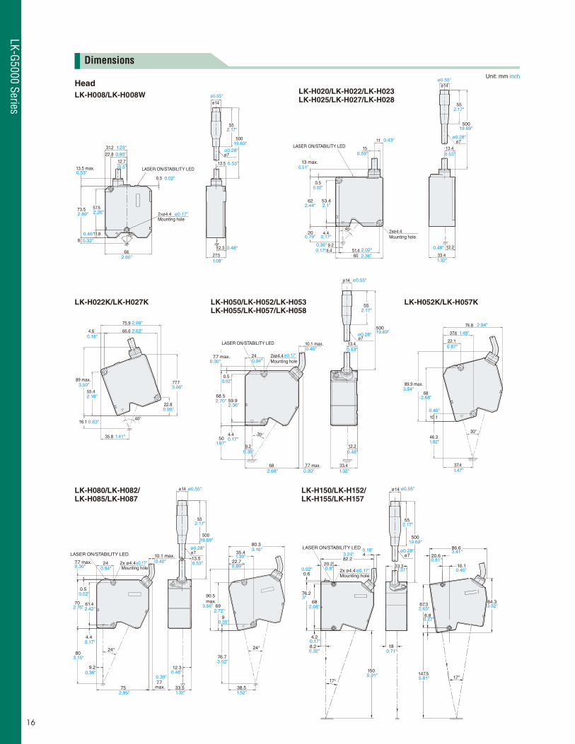
Unit: mm inch
Head
LK-H008/LK-H008W LK-H020/LK-H022/LK-H023LK-H025/LK-H027/LK-H028
LK-H050/LK-H052/LK-H053LK-H055/LK-H057/LK-H058
LK-H052K/LK-H057K
LK-H080/LK-H082/LK-H085/LK-H087
LK-H150/LK-H152/LK-H155/LK-H157
LK-H022K/LK-H027K
Dimensions
16
LK-G5000 Series
LK-G5000 Series
ø7 ø0.28"Cable length (0.7 m, 2 m, 5 m, 10 m, 20 m, 30 m)(2.30', 6.56', 16.40', 32.81', 65.62', 98.42')
11.5
26
3355 ø141.30"
1.02"
2.17"
0.45"
ø0.55"
ø7 ø0.28"Cable length (5 m, 10 m) (16.40', 32.81')
55
ø14
55
ø14ø0.55" ø0.55"
2.17" 2.17"
128 (65)65
6
9
124
47
34.5 79.5 4xM4 Depth: 6
2.56" 5.04"
1.36" 3.13"0.24"
0.35"
1.85"
(2.56")
4.88"
0.24"
(65) 105.565
9
DIN-rail mounting position
6
124 35.9
62.1
47
14 79.5 4xM4 Depth: 6
(2.56")2.56" 4.15"
2.44"
0.35"
3.13"0.55" 0.24"
1.85"
1.41"
0.24"
4.88"
0.24"
6
13.514
M4 Depth: 66
114
13.5
M4 Depth: 6
DIN-rail mounting position
26.326.3 (65)128 (65) 105.5
35.9
62.1
124124
1.04"
0.24"
4.49"
0.53"
4.88"
5.04" (2.56") (2.56") 4.15"
1.41"
2.44"
0.55"
0.53"
0.24"
1.04"
4.88"
0.24"
1.04"
114
13.5
(3.2)
M4 Depth: 6
DIN-rail mounting position
14
M4 Depth: 6
6 6
128 (13.2) (13.2) 105.526.3 26.3
124 124 35.9
62.1
(3.2)
13.5
4.88"
0.24"
5.04"
(0.52") (0.52")
(0.13")
0.53"
0.24"
1.04" 4.15"
2.44"
1.41"
0.24"
0.55"
0.53"
(0.13")
4.88"
0.24"4.49" 114
13.5
(3.2)
M4 Depth: 6
6
DIN-rail mounting position
M4 Depth: 6
14
6
26.3 (13.2) 105.5128 (13.2)26.3
124124
62.1
13.5
(3.2)
4.88"
0.24"
1.04" 5.04"
(0.52") (0.52")
(0.13")
0.53"
0.24"4.49"
0.24"
1.04" 4.15"
0.24"
0.55"
0.53"
(0.13")
4.88" 35.9
2.44"
1.41"
6 43
51
170.9(Effective display area)
237
128.2(Effective
display area)
178 167
9.33" 0.24"
1.69"
2.01"
6.57"
6.73"
7.01"
5.05"
62 min.
45 +0.6 0
75 +0.6 0
100 min.
2.44"
3.94"
1.77" +0.02"0
2.95"+0.02"0
8.525
13
Panel mounting ring
Panel thickness0.5 to 5
4662
8091 74.5
2.44"1.81"
0.51"0.02" to 0.20"
0.33"
0.98"
2.93"3.58"3.15"
AVOID EXPOSURELASER RADIATIONIS EMITTED FROMTHIS APERTURE.
LASER RADIATION-DO NOT STARE INTO BEAM
CAUTION
SEMICONDUCTOR LASERWAVELENGTHMAXIMUM OUTPUTCLASS LASER PRODUCT
655nm0.3mW
FDA
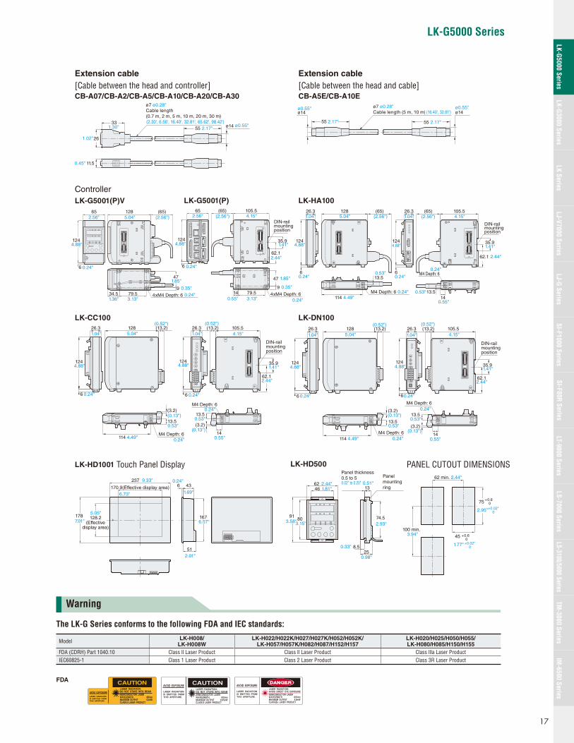
Extension cable
[Cable between the head and controller]CB-A07/CB-A2/CB-A5/CB-A10/CB-A20/CB-A30
Extension cable
[Cable between the head and cable]CB-A5E/CB-A10E
Controller
LK-G5001(P)V LK-G5001(P) LK-HA100
LK-CC100
LK-HD1001 Touch Panel Display
LK-DN100
LK-HD500 PANEL CUTOUT DIMENSIONS
The LK-G Series conforms to the following FDA and IEC standards:
Model LK-H008/LK-H008W
LK-H022/H022K/H027/H027K/H052/H052K/LK-H057/H057K/H082/H087/H152/H157
LK-H020/H025/H050/H055/LK-H080/H085/H150/H155
FDA (CDRH) Part 1040.10 Class ll Laser Product Class ll Laser Product Class llla Laser ProductIEC60825-1 Class 1 Laser Product Class 2 Laser Product Class 3R Laser Product
Warning
17
LK-G5000 SeriesLK-G3000 Series
LJ-G SeriesSI-F1000 Series
SI-F80R SeriesLS-7000 Series
LS-3100/5000 SeriesTM
-3000 SeriesIM
-6500 SeriesLK Series
LJ-V7000 SeriesLT-9000 Series
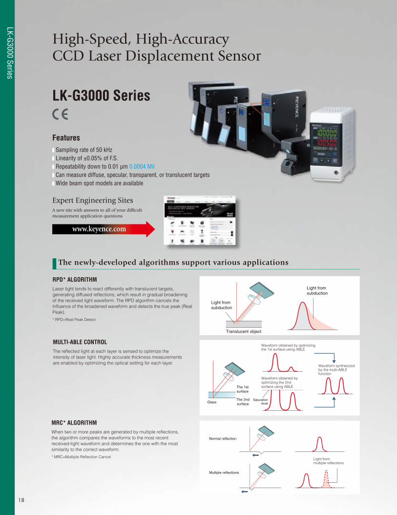
High-Speed, High-Accuracy CCD Laser Displacement Sensor
MULTI-ABLE CONTROLThe refl ected light at each layer is sensed to optimize the
intensity of laser light. Highly accurate thickness measurements
are enabled by optimizing the optical setting for each layer.
MRC* ALGORITHMWhen two or more peaks are generated by multiple refl ections,
the algorithm compares the waveforms to the most recent
received-light waveform and determines the one with the most
similarity to the correct waveform.
* MRC=Multiple Refl ection Cancel
RPD* ALGORITHMLaser light tends to react differently with translucent targets,
generating diffused refl ections, which result in gradual broadening
of the received light waveform. The RPD algorithm cancels the
infl uence of the broadened waveform and detects the true peak (Real
Peak).
* RPD=Real Peak Detect
LK-G3000 Series
Features Sampling rate of 50 kHz Linearity of ±0.05% of F.S. Repeatability down to 0.01 μm 0.0004 Mil Can measure diffuse, specular, transparent, or translucent targets Wide beam spot models are available
Expert Engineering SitesA new site with answers to all of your diffi cult measurement application questions
www.keyence.com
The newly-developed algorithms support various applications
Translucent object
Light fromsubduction
Light fromsubduction
The 1stsurface
GlassThe 2ndsurface
Waveform obtained by optimizingthe 1st surface using ABLE
Waveform synthesizedby the multi-ABLEfunction
Waveform obtained byoptimizing the 2ndsurface using ABLE
Saturationlevel
Light frommultiple reflections
Normal reflection
Multiple reflections
18
LK-G3000 Series
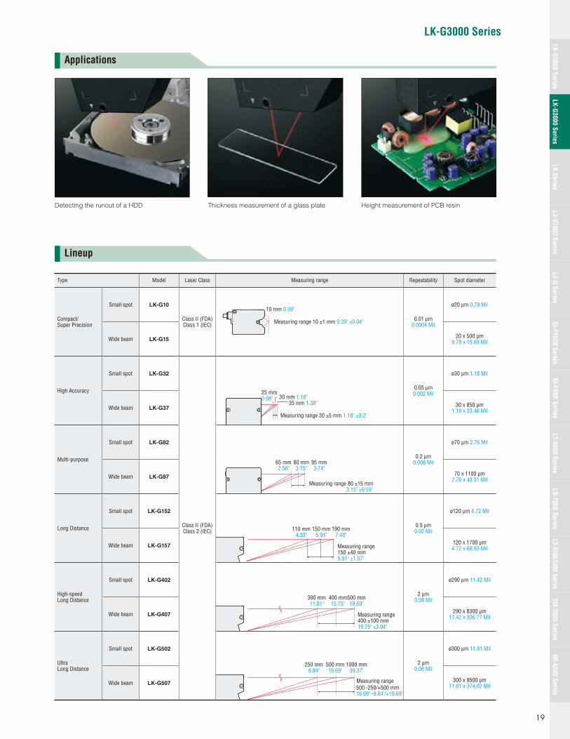
LK-G3000 Series
Type Model Laser Class Measuring range Repeatability Spot diameter
Compact/Super Precision
Small spot LK-G10
Class II (FDA)Class 1 (IEC)
0.01 μm0.0004 Mil
ø20 μm 0.79 Mil
Wide beam LK-G1520 x 500 μm
0.79 x 19.69 Mil
High Accuracy
Small spot LK-G32
Class II (FDA)Class 2 (IEC)
0.05 μm0.002 Mil
ø30 μm 1.18 Mil
Wide beam LK-G3730 x 850 μm
1.18 x 33.46 Mil
Multi-purpose
Small spot LK-G82
0.2 μm0.008 Mil
ø70 μm 2.76 Mil
Wide beam LK-G8770 x 1100 μm
2.76 x 43.31 Mil
Long Distance
Small spot LK-G152
0.5 μm0.02 Mil
ø120 μm 4.72 Mil
Wide beam LK-G157120 x 1700 μm 4.72 x 66.93 Mil
High-speed Long Distance
Small spot LK-G402
2 μm0.08 Mil
ø290 μm 11.42 Mil
Wide beam LK-G407290 x 8300 μm
11.42 x 326.77 Mil
Ultra Long Distance
Small spot LK-G502
2 μm0.08 Mil
ø300 μm 11.81 Mil
Wide beam LK-G507300 x 9500 μm
11.81 x 374.02 Mil
10 mm 0.39"
Measuring range 10 ±1 mm 0.39" ±0.04"
30 mm 1.18"25 mm0.98"
35 mm 1.38"
Measuring range 30 ±5 mm 1.18" ±0.2"
65 mm2.56"
80 mm3.15"
95 mm3.74"
Measuring range 80 ±15 mm3.15" ±0.59"
110 mm4.33"
150 mm5.91"
190 mm7.48"
Measuring range150 ±40 mm5.91" ±1.57"
300 mm11.81"
400 mm15.75"
500 mm19.69"
Measuring range400 ±100 mm15.75" ±3.94"
250 mm9.84"
500 mm19.69"
1000 mm39.37"
Measuring range500 -250/+500 mm19.69" -9.84"/+19.69"
Applications
Lineup
Detecting the runout of a HDD Height measurement of PCB resinThickness measurement of a glass plate
19
LK-G5000 SeriesLK-G3000 Series
LJ-G SeriesSI-F1000 Series
SI-F80R SeriesLS-7000 Series
LS-3100/5000 SeriesTM
-3000 SeriesIM
-6500 SeriesLK Series
LJ-V7000 SeriesLT-9000 Series
Specifi cations
Sensor heads
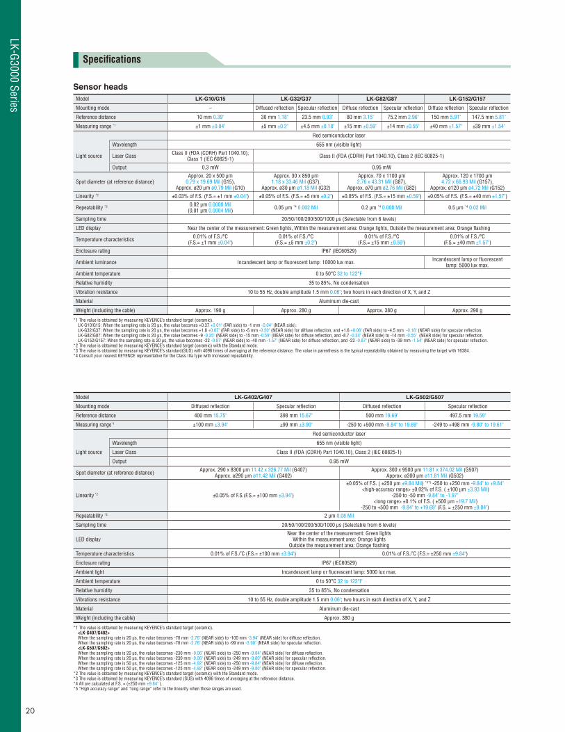
Model LK-G10/G15 LK-G32/G37 LK-G82/G87 LK-G152/G157
Mounting mode – Diffused refl ection Specular refl ection Diffuse refl ection Specular refl ection Diffuse refl ection Specular refl ection
Reference distance 10 mm 0.39" 30 mm 1.18" 23.5 mm 0.93" 80 mm 3.15" 75.2 mm 2.96" 150 mm 5.91" 147.5 mm 5.81"
Measuring range *1 ±1 mm ±0.04" ±5 mm ±0.2" ±4.5 mm ±0.18" ±15 mm ±0.59" ±14 mm ±0.55" ±40 mm ±1.57" ±39 mm ±1.54"
Red semiconductor laser
Light source
Wavelength 655 nm (visible light)
Laser Class Class II (FDA (CDRH) Part 1040.10), Class 1 (IEC 60825-1) Class II (FDA (CDRH) Part 1040.10), Class 2 (IEC 60825-1)
Output 0.3 mW 0.95 mW
Spot diameter (at reference distance)Approx. 20 x 500 μm
0.79 x 19.69 Mil (G15), Approx. ø20 μm ø0.79 Mil (G10)
Approx. 30 x 850 μm 1.18 x 33.46 Mil (G37),
Approx. ø30 μm ø1.18 Mil (G32)
Approx. 70 x 1100 μm 2.76 x 43.31 Mil (G87),
Approx. ø70 μm ø2.76 Mil (G82)
Approx. 120 x 1700 μm 4.72 x 66.93 Mil (G157),
Approx. ø120 μm ø4.72 Mil (G152)
Linearity *2 ±0.03% of F.S. (F.S.= ±1 mm ±0.04") ±0.05% of F.S. (F.S.= ±5 mm ±0.2") ±0.05% of F.S. (F.S.= ±15 mm ±0.59") ±0.05% of F.S. (F.S.= ±40 mm ±1.57")
Repeatability *3 0.02 μm 0.0008 Mil (0.01 μm 0.0004 Mil) 0.05 μm *4 0.002 Mil 0.2 μm *4 0.008 Mil 0.5 μm *4 0.02 Mil
Sampling time 20/50/100/200/500/1000 μs (Selectable from 6 levels)
LED display Near the center of the measurement: Green lights, Within the measurement area: Orange lights, Outside the measurement area: Orange fl ashing
Temperature characteristics 0.01% of F.S./°C (F.S.= ±1 mm ±0.04")
0.01% of F.S./°C (F.S.= ±5 mm ±0.2")
0.01% of F.S./°C (F.S.= ±15 mm ±0.59")
0.01% of F.S./°C (F.S.= ±40 mm ±1.57")
Enclosure rating IP67 (IEC60529)
Ambient luminance Incandescent lamp or fl uorescent lamp: 10000 lux max. Incandescent lamp or fl uorescent lamp: 5000 lux max.
Ambient temperature 0 to 50°C 32 to 122°F
Relative humidity 35 to 85%, No condensation
Vibration resistance 10 to 55 Hz, double amplitude 1.5 mm 0.06"; two hours in each direction of X, Y, and Z
Material Aluminum die-cast
Weight (including the cable) Approx. 190 g Approx. 280 g Approx. 380 g Approx. 290 g
*1 The value is obtained by measuring KEYENCE’s standard target (ceramic).LK-G10/G15: When the sampling rate is 20 μs, the value becomes +0.37 +0.01" (FAR side) to -1 mm -0.04" (NEAR side). LK-G32/G37: When the sampling rate is 20 μs, the value becomes +1.8 +0.07" (FAR side) to -5 mm -0.20" (NEAR side) for diffuse refl ection, and +1.6 +0.06" (FAR side) to -4.5 mm -0.18" (NEAR side) for specular refl ection.LK-G82/G87: When the sampling rate is 20 μs, the value becomes -9 -0.35" (NEAR side) to -15 mm -0.59" (NEAR side) for diffuse refl ection, and -8.7 -0.34" (NEAR side) to -14 mm -0.55" (NEAR side) for specular refl ection.LK-G152/G157: When the sampling rate is 20 μs, the value becomes -22 -0.87" (NEAR side) to -40 mm -1.57" (NEAR side) for diffuse refl ection, and -22 -0.87" (NEAR side) to -39 mm -1.54" (NEAR side) for specular refl ection.
*2 The value is obtained by measuring KEYENCE’s standard target (ceramic) with the Standard mode.*3 The value is obtained by measuring KEYENCE’s standard(SUS) with 4096 times of averaging at the reference distance. The value in parenthesis is the typical repeatability obtained by measuring the target with 16384.*4 Consult your nearest KEYENCE representative for the Class IIIa type with increased repeatability.
Model LK-G402/G407 LK-G502/G507
Mounting mode Diffused refl ection Specular refl ection Diffused refl ection Specular refl ection
Reference distance 400 mm 15.75" 398 mm 15.67" 500 mm 19.69" 497.5 mm 19.59"
Measuring range*1 ±100 mm ±3.94" ±99 mm ±3.90" -250 to +500 mm -9.84" to 19.69" -249 to +498 mm -9.80" to 19.61"
Red semiconductor laser
Light source
Wavelength 655 nm (visible light)
Laser Class Class II (FDA (CDRH) Part 1040.10), Class 2 (IEC 60825-1)
Output 0.95 mW
Spot diameter (at reference distance) Approx. 290 x 8300 μm 11.42 x 326.77 Mil (G407)Approx. ø290 μm ø11.42 Mil (G402)
Approx. 300 x 9500 μm 11.81 x 374.02 Mil (G507)Approx. ø300 μm ø11.81 Mil (G502)
Linearity *2 ±0.05% of F.S.(F.S.= ±100 mm ±3.94")
±0.05% of F.S. ( ±250 μm ±9.84 Mil) *4*5 -250 to +250 mm -9.84" to +9.84" <high-accuracy range> ±0.02% of F.S. ( ±100 μm ±3.93 Mil)
-250 to -50 mm -9.84" to -1.97" <long range> ±0.1% of F.S. ( ±500 μm ±19.7 Mil)
-250 to +500 mm -9.84" to +19.69" (F.S. = ±250 mm ±9.84")
Repeatability *3 2 μm 0.08 Mil
Sampling time 20/50/100/200/500/1000 μs (Selectable from 6 levels)
LED displayNear the center of the measurement: Green lights
Within the measurement area: Orange lightsOutside the measurement area: Orange fl ashing
Temperature characteristics 0.01% of F.S./˚C (F.S.= ±100 mm ±3.94") 0.01% of F.S./˚C (F.S.= ±250 mm ±9.84")
Enclosure rating IP67 (IEC60529)
Ambient light Incandescent lamp or fl uorescent lamp: 5000 lux max.
Ambient temperature 0 to 50°C 32 to 122°F
Relative humidity 35 to 85%, No condensation
Vibrations resistance 10 to 55 Hz, double amplitude 1.5 mm 0.06"; two hours in each direction of X, Y, and Z
Material Aluminum die-cast
Weight (including the cable) Approx. 380 g
*1 The value is obtained by measuring KEYENCE’s standard target (ceramic).<LK-G407/G402>When the sampling rate is 20 μs, the value becomes -70 mm -2.76" (NEAR side) to -100 mm -3.94" (NEAR side) for diffuse refl ection.When the sampling rate is 20 μs, the value becomes -70 mm -2.76" (NEAR side) to -99 mm -3.90" (NEAR side) for specular refl ection.<LK-G507/G502>When the sampling rate is 20 μs, the value becomes -230 mm -9.06" (NEAR side) to -250 mm -9.84" (NEAR side) for diffuse refl ection.When the sampling rate is 20 μs, the value becomes -230 mm -9.06" (NEAR side) to -249 mm -9.80" (NEAR side) for specular refl ection.When the sampling rate is 50 μs, the value becomes -125 mm -4.92" (NEAR side) to -250 mm -9.84" (NEAR side) for diffuse refl ection.When the sampling rate is 50 μs, the value becomes -125 mm -4.92" (NEAR side) to -249 mm -9.80" (NEAR side) for specular refl ection.
*2 The value is obtained by measuring KEYENCE’s standard target (ceramic) with the Standard mode.*3 The value is obtained by measuring KEYENCE’s standard (SUS) with 4096 times of averaging at the reference distance. *4 All are calculated at F.S. = (±250 mm ±9.84" ).*5 “High accuracy range” and “long range” refer to the linearity when those ranges are used.
20
LK-G3000 Series
LK-G3000 Series
Controller
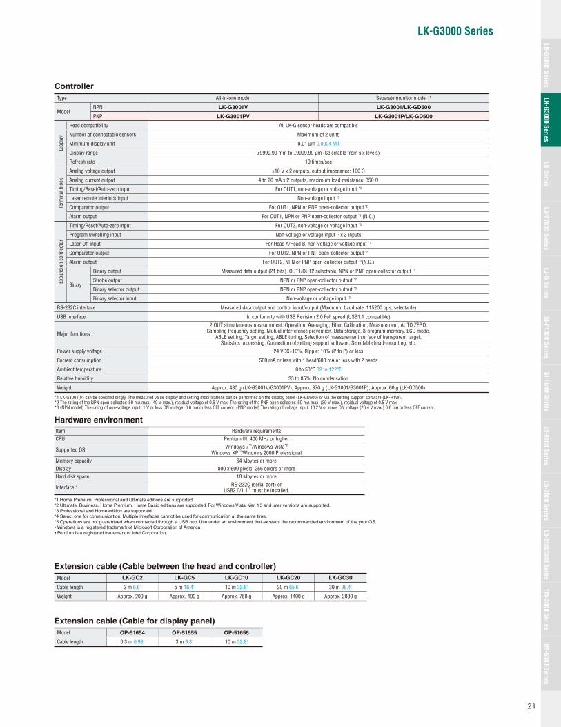
Type All-in-one model Separate monitor model *1
ModelNPN LK-G3001V LK-G3001/LK-GD500
PNP LK-G3001PV LK-G3001P/LK-GD500
Disp
lay
Head compatibility All LK-G sensor heads are compatible
Number of connectable sensors Maximum of 2 units
Minimum display unit 0.01 μm 0.0004 Mil
Display range ±9999.99 mm to ±9999.99 μm (Selectable from six levels)
Refresh rate 10 times/sec
Term
inal
blo
ck
Analog voltage output ±10 V x 2 outputs, output impedance: 100 Ω
Analog current output 4 to 20 mA x 2 outputs, maximum load resistance: 350 Ω
Timing/Reset/Auto-zero input For OUT1, non-voltage or voltage input *3
Laser remote interlock input Non-voltage input *3
Comparator output For OUT1, NPN or PNP open-collector output *2
Alarm output For OUT1, NPN or PNP open-collector output *3 (N.C.)
Expa
nsio
n co
nnec
tor
Timing/Reset/Auto-zero input For OUT2, non-voltage or voltage input *3
Program switching input Non-voltage or voltage input *3 x 3 inputs
Laser-Off input For Head A/Head B, non-voltage or voltage input *3
Comparator output For OUT2, NPN or PNP open-collector output *2
Alarm output For OUT2, NPN or PNP open-collector output *2(N.C.)
Binary
Binary output Measured data output (21 bits), OUT1/OUT2 selectable, NPN or PNP open-collector output *2
Strobe output NPN or PNP open-collector output *2
Binary selector output NPN or PNP open-collector output *2
Binary selector input Non-voltage or voltage input *3
RS-232C interface Measured data output and control input/output (Maximum baud rate: 115200 bps, selectable)
USB interface In conformity with USB Revision 2.0 Full speed (USB1.1 compatible)
Major functions
2 OUT simultaneous measurement, Operation, Averaging, Filter, Calibration, Measurement, AUTO ZERO, Sampling frequency setting, Mutual interference prevention, Data storage, 8-program memory, ECO mode,
ABLE setting, Target setting, ABLE tuning, Selection of measurement surface of transparent target, Statistics processing, Connection of setting support software, Selectable head-mounting, etc.
Power supply voltage 24 VDC±10%, Ripple: 10% (P to P) or less
Current consumption 500 mA or less with 1 head/600 mA or less with 2 heads
Ambient temperature 0 to 50°C 32 to 122°F
Relative humidity 35 to 85%, No condensation
Weight Approx. 480 g (LK-G3001V/G3001PV), Approx. 370 g (LK-G3001/G3001P), Approx. 60 g (LK-GD500)
*1 LK-G3001(P) can be operated singly. The measured value display and setting modifi cations can be performed on the display panel (LK-GD500) or via the setting support software (LK-H1W). *2 The rating of the NPN open-collector: 50 mA max. (40 V max.), residual voltage of 0.5 V max. The rating of the PNP open collector: 50 mA max. (30 V max.), residual voltage of 0.5 V max. *3 (NPN model) The rating of non-voltage input: 1 V or less ON voltage, 0.6 mA or less OFF current. (PNP model) The rating of voltage input: 10.2 V or more ON voltage (26.4 V max.) 0.6 mA or less OFF current.
Hardware environment
Item Hardware requirementsCPU Pentium III, 400 MHz or higher
Supported OS Windows 7*1/Windows Vista*2
Windows XP*3/Windows 2000 ProfessionalMemory capacity 64 Mbytes or moreDisplay 800 x 600 pixels, 256 colors or moreHard disk space 10 Mbytes or more
Interface*4 RS-232C (serial port) orUSB2.0/1.1*5 must be installed.
*1 Home Premium, Professional and Ultimate editions are supported.*2 Ultimate, Business, Home Premium, Home Basic editions are supported. For Windows Vista, Ver. 1.5 and later versions are supported.*3 Professional and Home edition are supported.*4 Select one for communication. Multiple interfaces cannot be used for communication at the same time.*5 Operations are not guaranteed when connected through a USB hub. Use under an environment that exceeds the recommended environment of the your OS.• Windows is a registered trademark of Microsoft Corporation of America.• Pentium is a registered trademark of Intel Corporation.
Extension cable (Cable between the head and controller)
Model LK-GC2 LK-GC5 LK-GC10 LK-GC20 LK-GC30
Cable length 2 m 6.6' 5 m 16.4' 10 m 32.8' 20 m 65.6' 30 m 98.4'
Weight Approx. 200 g Approx. 400 g Approx. 750 g Approx. 1400 g Approx. 2000 g
Extension cable (Cable for display panel)
Model OP-51654 OP-51655 OP-51656
Cable length 0.3 m 0.98' 3 m 9.8' 10 m 32.8'
21
LK-G5000 SeriesLK-G3000 Series
LJ-G SeriesSI-F1000 Series
SI-F80R SeriesLS-7000 Series
LS-3100/5000 SeriesTM
-3000 SeriesIM
-6500 SeriesLK Series
LJ-V7000 SeriesLT-9000 Series

15
22.8
27
51.2
26.31.04"
11.5
9 to 11
71.7
2-ø4.4
Mounting hole
75°
ø0.17"
0.45"1.06"
0.59"
2.02"
0.90"
2.82"
0.35" to 0.43"
54 2.13"
ø14
552.17"
19.69"500
ø0.55"
ø0.28"ø7
85
13.5
3.35"
0.98"
2.99" 2.64"
0.16"
0.53"
40°
25Mounting hole
2-ø4.5
76 67
4 25 to 35
ø0.18"26
13
1.02"
0.51"
0.98" to 1.38"
ø0.55"
2.17"
ø0.28"500
ø14
55
ø7
19.69"
2.99"
0.53" 0.71"
36
13.5
25°
95 3.74"
1.42"
25 0.98"0.02"0.6
18
65 to 952.56" to 3.74"
40.16"
Mounting hole
2-ø4.5 ø0.18"
76
672.64"
19.69"
ø7ø0.28"
ø14 ø0.55"
500
2.17"55
Mounting hole
8.2
20.2
82.2
4
2-ø4.4 ø0.17"
76.2 68
4.2
17°110 to 190
4.33" to 7.48"
33.3
180.71"
1.31"
0.16"
3.24"
0.80"
0.17"
0.32"
2.68"3.00"
552.17"
ø0.55"
ø0.28"
50019.69"ø7
ø14
108 4.25" 1 0.04"
200.79"0.7
0.03"
853.35" 76
2.99"
2 - ø4.4 ø0.17" mounting hole
4.50.18"
8.2 0.32"
10.2°
250 to 1000(300 to 500)
9.84" to 39.37"(11.81" to 19.69")
19.2
36.2
ø14 ø0.55"
ø7ø0.28"
552.17"
50019.69"
1.43"
0.76"
Sensor heads
LK-G10/G15 LK-G32/G37
Diffused refl ection type mounting
LK-G152/G157
Diffused refl ection type mountingLK-G82/G87
Diffused refl ection type mounting
LK-G402/G407/G502/G507Data in ( ) applies to LK-G407/G402
Diffused refl ection type mounting
DimensionsUnit: mm inch
22
LK-G3000 Series
LK-G3000 Series
0.24"
4-M4 screws,
Depth: 6
6
62 117 (65)
33 70
43
9.5
1244.88"
2.44" 4.61"
0.24"
0.37"
2.76"1.30"
1.69"
(2.56")
4-M4 screws,
Depth: 6
DIN-rail
mounting position
6
62 (65) 95
13.5 70
66.1
124
9.5
4.88"
2.44" 3.74"
2.60"
431.69"
0.37"
2.76"0.53"
0.24"
(2.56")
0.24"
35.91.41"
ø7 ø0.28"Cable length (2 m, 5 m, 10 m, 20 m, 30 m)(6.56', 16.40', 32.81', 65.62', 98.42')
11.5
26
33
55
ø14
1.30"
1.02"
2.17"
0.45"
ø0.55"
Panel-mounting ring
Panel thickness
8091
46
62
8.5
74.5
0.5 to 5 0.02" to 0.2"
13
25
2.44"
3.58" 3.15"
1.81"0.51"
2.93"
0.33"
0.98"
1003.94"
min.
62
min.
75+0.6 0
45+0.6 0
2.44"
+0.02"2.95" 0
1.77" +0.02"0
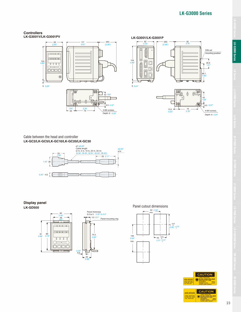
ControllersLK-G3001V/LK-G3001PV
Cable between the head and controllerLK-GC2/LK-GC5/LK-GC10/LK-GC20/LK-GC30
Display panel
LK-GD500 Panel cutout dimensions
LK-G3001/LK-G3001P
23
LK-G5000 SeriesLK-G3000 Series
LJ-G SeriesSI-F1000 Series
SI-F80R SeriesLS-7000 Series
LS-3100/5000 SeriesTM
-3000 SeriesIM
-6500 SeriesLK Series
LJ-V7000 SeriesLT-9000 Series

Type Long-distanceModel LK-503
Measurement mode High-precision mode Long-range mode
Reference distance
Repeatability 10 μm 0.39 Mil 50 μm 1.95 MilLinearity ±0.1% of F.S.Sampling cycle 1,024 μs
Type Compact/high-accuracy High-precision StandardModel LK-011 LK-031/036 LK-081/086
Measurement mode Normal Mirror surface – –
Reference distance
Repeatability 0.1 μm 0.004 Mil 1 μm 0.039 Mil 3 μm 0.12 Mil
Linearity ±0.25% of F.S. ±0.1% of F.S.
Sampling cycle 128/256/512/2,048 μs 512 μs 1,024 μs
CCD Laser Displacement Sensors
The LFTC circuit enables measurement of multicolored or patterned
targets. Low refl ectance targets, such as black rubber, can be measured
without additional adjustment.
KEYENCE’s unique optical system
minimizes lens aberration to give the
LK-031 a minimum spot diameter of
30 μm 1.18 Mil. This enables the
surface contour of a target to be
accurately measured.
LK Series
Features Linearity of ±0.1% of F.S. Repeatability of 1 μm 0.04 Mil 30 μm 1.18 Mil diameter beam spot Ultra long measuring distance up to 750 mm 29.53" Measurement unaffected by color, surface texture or stray light
Expert Engineering SitesA new site with answers to all of your diffi cult measurement application questions
www.keyence.com
Measurement of various target surfaces
Laser beam spot of 30 μm 1.18 Mil diameter
Lineup
10 ±1mm0.39"±0.04"
7.0 ±0.9 mm0.28"±0.04"
30 ±5 mm1.18"±0.20"
80 ±15 mm3.15"±0.59"
350 ±100 mm13.78"±3.94"
500 ±250 mm19.69"±9.84"
11mm0.43"
10mm0.39"
9mm0.35"
7.9mm0.31"
7.0mm0.28"
6.1mm0.24"
35mm1.38"
30mm1.18"
25mm0.98"
95 mm3.74"
80 mm3.15"
65 mm2.56"
450 mm17.71"
350 mm13.78"
250 mm9.84"
750 mm29.53"
500 mm19.69"
250 mm9.84"
24
LK Series

LK Series
11013 76
140
90100 112
4-ø5(mounting hole)
(60)
35.4
172
0 to 140°
6.77"
5.51"
4.33"
ø0.20"
3.54"3.94" 4.41"
0.51"2.99" (2.36")
1.39"
27.3 1.07"
ø15
ø5
43
7.9 0.31"
500
45°
7 9 to 11
3
3
2-ø3.2 (mounting hole)
42.7
33
39.8
17.7
ø0.59"
1.70"
19.69"
ø0.13"
1.57" 0.12"
0.28" 0.35" to 0.43"
0.12"
1.68"
1.30"
ø0.20"
0.70"
85
7667
40° 25 to 35
13.5
4
25
26
13
ø7
ø15
43
500
2-ø4.5(mounting hole)
ø0.59"
1.70"
19.69"ø0.28"1.02"
3.35"
0.98"ø0.18"
2.99"2.64"
0.98" to 1.38"
0.53"0.51"0.16"
95
76 67
25° 65 to 95
13.5
4
2536
18
ø7
ø15
43
500
2-ø4.5(mounting hole)
ø0.18"
3.74"
0.98"
2.99" 2.64"
0.53"
0.16"2.56" to 3.74"
0.71"
1.42"ø0.28" 19.69"
1.70"
ø0.59" 120
33.5 2-ø5.4
79
90
5
250 to 750
13.8 24.5
ø15
ø7, Cable length: 500
47.8
43
8° (11°)
(mounting hole)
Measurement reference position
4.72"
ø0.21"
1.32"
3.54"
3.11"
0.20"
9.84" to 29.53"(250 to 450)
(9.84" to 17.72")
0.54" 0.96"
1.88"
ø0.59"
ø0.28"
1.69"
19.69"
Specifi cations
Type Compacthigh-accuracy High-precision Standard Long-distance *4
ModelSensor head LK-011 LK-031/036 LK-081/086 LK-503
Controller LK-3101 LK-2001/2011 LK-2101/2111 LK-2503
Measurement mode Normal(mirror surface) — High-precision mode Long-range mode
Reference distance 10 mm (7.0 mm)0.39" (0.28") 30 mm 1.18" 80 mm 3.15" 350 mm 13.78" 500 mm 19.69"
Measuring range ±1 mm (±0.9 mm)±0.04" (±0.04") ±5 mm ±0.20" ±15 mm ±0.59" ±100 mm ±3.94" ±250 mm ±9.84"
Light source Visible red semiconductor laserOutput 0.95 mWWavelength 670 nm 690 nm
Laser ClassFDA (CDRH) Part 1040.10 Class II Laser ProductIEC 60825-1 Class 2 Laser Product
Spot diameter(at reference distance)
Approx. 20 μm0.79 Mil
Approx. 30 μm1.18 Mil (LK-031)
Approx. 30 x 850 μm1.18 x 33.46 Mil (LK-036)
Approx. 70 μm2.76 Mil (LK-081)
Approx. 70 x 1100 μm2.76 x 43.3 Mil (LK-086)
Approx. 0.7 mm 0.03"
Approx. 0.3 mm 0.01"
Repeatability 0.1 μm *1 0.004 Mil 1 μm *1 0.039 Mil 3 μm *1 0.12 Mil 10 μm *1 0.39 Mil 50 μm *1 1.97 MilLinearity ±0.25% of F.S. *2 ±0.1% of F.S. *2
Sampling cycle 128/256/512/2,048 μs selectable 512 μs 1024 μs
Analog outputVoltage output ±10 V (±9 V)
(0.1 μm 0.004 Mil/mV)*3±5 V
(1 μm 0.039 Mil/mV) *3±5 V
(3 μm 0.12 Mil/mV) *3±10 V
(10 μm 0.39 Mil/mV) *3±5 V
(50 μm 1.97 Mil/mV) *3
Impedance 100 ΩCurrent output 4 to 20 mA (Applicable load: 350 Ωmax.)
Alarm output NPN: 100 mA max. (40 V max.) (N.C.), Residual voltage: 1 V max.Other functions AUTO ZERO, Response selection, Shift/Span adjustment, Holding output in alarm conditionPower supply 24 VDC ±10%, Ripple: 10% (P to P) or lessCurrent consumption 400 mA max.
Temperature fl uctuation
Sensor head 0.04% of F.S./°C 0.01% of F.S./°C 0.02% of F.S./°CController 0.005% of F.S./°C 0.01% of F.S./°C
Enclosure rating IP64 IP67Ambient light Incandescent or fl uorescent lamp: 10000 lux max.Ambient temperature 0 to 50°C 32 to 122°FRelative humidity 35 to 85%, No condensation
HousingSensor head Aluminum die-castController Polycarbonate
Weight(including cable)
Sensor head Approx. 80 g Approx. 260 g Approx. 385 g Approx. 700 gController Approx. 515 g
*1 Repeatability was obtained using KEYENCE’s analog sensor controller (RD-50) with the number of averaging measurements set to 64. Note: The ripple of the analog output may be 1 mV or more due to common mode noise when observed with an oscilloscope or a high-speed A/D conver-sion board.
*2 Linearity was obtained using KEYENCE’s standard target (Zirconia block gauge: LK-031/036, LK-081/086, LK-011, White ceramic block gauge: LK-503).*3 When measurement is impossible, 12 V (31.2 mA) is output.*4 The LK-503 can both be used in High-precision mode or Long-range mode.
Sensor headLK-011 LK-031/036 LK-081/086 LK-503
* Data in ( ) applies to
at high-precision mode.
LA SA A A A A AA AAA A -
A A A A A SAA A A AA AA A A A A
SA A AA A A A A A AA A LA SA A 6A0nA
A A A AA A A A A AA A A 0AA5A A
A A LSA A A A A AA AAA A
A LA SS AA LA SA A A A A A A A A
A A A AAA AA A A AAA A
A AA AA AAAA SA A A
LASER RADIATIONIS EMITTED FROMTHIS APERTURE.
AAAAAAA
LASER RADIATIONWHEN OPEN.DO NOT STARE INTOBEAM.
LASER RADIATION-DO NOT STARE INTO BEAM
SEMICONDUCTOR LASERMAXIMUM OUTPUTPULSED RADIATIONCLASS II LASER PRODUCT
690nm0.95mW
CAUTION
AVOID EXPOSURELASER RADIATIONIS EMITTED FROMTHIS APERTURE.
CAUTIONLASER RADIATIONWHEN OPEN.DO NOT STARE INTO BEAM.
ControllersLK-3101/2001/2011/2101/2111/2503
Extension cable (Optional)Cable length Model
2 m 6.6' LK-C2
5 m 16.4' LK-C5
10 m 32.8' LK-C10
DimensionsUnit: mm inch
25
LK-G5000 SeriesLK-G3000 Series
LJ-G SeriesSI-F1000 Series
SI-F80R SeriesLS-7000 Series
LS-3100/5000 SeriesTM
-3000 SeriesIM
-6500 SeriesLK Series
LJ-V7000 SeriesLT-9000 Series

World's fastest
Industry best
High-speed 2D/3D Laser Scanner
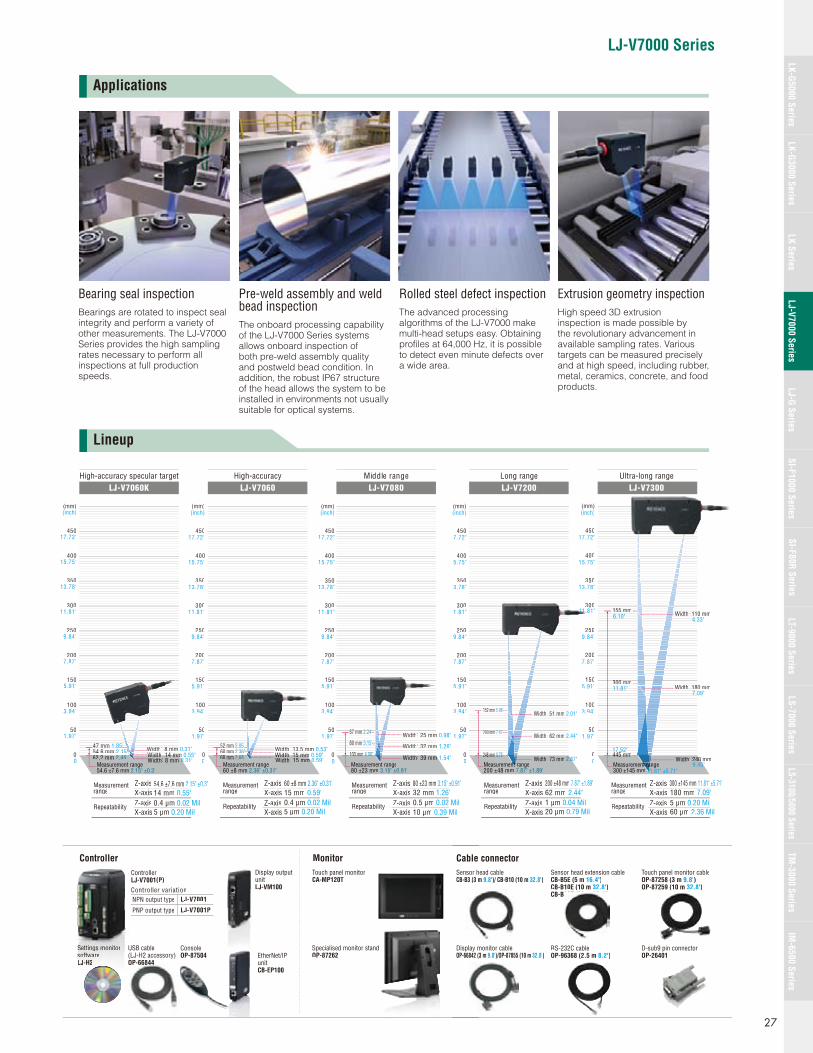
The LJ-V7000 Series was designed to achieve the world’s fastest
sampling speed. No other laser based 3D measurement system on the
market even comes close.
The LJ-V7000 can measure products moving on high-speed lines with
high precision and no loss of data.
For example, the LJ-V7000 can measure targets moving at 6.4 m/s with a
profi le pitch of 0.1 mm 0.0039".
Normally, detection stability is inversely proportional to speed. However,
the LJ-V7000 Series incorporates cutting edge technology that greatly
improves both variables. Shapes are accurately measured even where
there is a high variation in target refl ectivity under the same optical axis.
LJ-V7000 Series
Features An emphasis on inline measurement The world's fastest at 64,000 profi les/sec. Blue laser optical system
Expert Engineering SitesA new site with answers to all of your diffi cult measurement application questions
www.keyence.com
240 times greater than conventional devices
64,000 profiles/sec. sampling 12,800,000 points/sec.
64 times the dynamic range of conventional devices
Overwhelming responsiveness to target properties to optimize output stability
NEW
LJ-V7000 Series
26
LJ-V7000 Series
13.78"
15.75"
17.72"
7.87"
9.84"
11.81"
5.91"
3.94"
1.97"
0
(inch)
13.78"
15.75"
17.72"
7.87"
9.84"
11.81"
5.91"
3.94"
1.97"
0
(inch)
13.78"
15.75"
17.72"
7.87"
9.84"
11.81"
5.91"
3.94"
1.97"
0
(inch)
Width: 8 mm 0.31"0WidthWidthWidth:: 14 mm14 14 mm 0.55"WidthWidthWidth::: 8 mm8 mm8 mm 0.31"
Measurement range54.6 ±7.6 mm 2.15" ±0.3"
54.6 mm54 6 mm54 6 mm 2.15"2 152 15"62 262.2 mm 2 45"2.45"
47 mm47 mm47 mm 1.85"1.851 85
0.4 μm 0.02 Mil
54.6 ±7.6 mm 2.15" ±0.3"14 mm 0.55"
5 μm 0.20 Mil
Width: m 15 mm 0.59"0WidthWid hWidth:: 15 mm 15 15 mm 0.59"WidthWidthWidth::: 13.5 mm 13 5 m13 5 m 0.53"
Measurement range60 ±8 mm 2.36" ±0.31"
0.4 μm 0.02 Mil
60 ±8 mm 2.36" ±0.31"15 mm 0.59"
5 μm 0.20 Mil
60 mm 60 mm60 mm 2.36"2 362 36"6868 mm 2 68"2.68"
52 mm 552 mm 2.05"052 05
57 mm 57 mm57 mm 2.24"2 242 24"
80 mm 80 mm 3.15"3 15
103 mm103103 mm 4 06"4 06"4.06
WidthWidthWid h:: 25 mm25 mm25 0.98"
Width: m 39 mm 1.54"
WidthWidthWidth:: 32 mm32 mm32 mm 1.26"
Measurement range80 ±23 mm 3.15" ±0.91"
0.5 μm 0.02 Mil
80 ±23 mm 3.15" ±0.91"32 mm 1.26"
10 μm 0.39 Mil
""
Controller variationLJ-V7001NPN output type
LJ-V7001PPNP output type
Controller LJ-V7001(P)
SSSSeSeSeSeSSeSeSSSeSettttttttttttttt iniiningsgsgsgsgsgs m mmmmmmmonononononitiititittitoroorororro sossossssossos ffftfffftttwawawawawaarererrerr LLJLJLLJLJLLL H-H-H-H-HHHHH2222
ConsoleOP-87504
Display output unit LJ-VM100
USB cable (LJ-H2 accessory)OP-66844OP 66844
Controller
EtherNet/IP unit CB-EP100
350
400
450
200
250
300
150
100
50
0
(mm)
350
400
450
200
250
300
150
100
50
0
(mm)
Repeatability
Measurement range
Repeatability
Measurement range
Z-axisX-axisZ-axisX-axis
Monitor
High-accuracy specular targetLJ-V7060K
High-accuracyLJ-V7060
Middle rangeLJ-V7080
Touch panel monitorCA-MP120T
Specialised monitor standOP-87262
350
400
450
200
250
300
150
100
50
0
(mm)
Z-axisX-axisZ-axisX-axis
Repeatability
Measurement range
Z-axisX-axisZ-axisX-axis
3.78"
5.75"
7.72"
7.87"
9.84"
1.81"
5.91"
3.94"
1.97"
0
(inch)
13.78"
15.75"
17.72"
7.87"
9.84"
5.91"
3.94"
1.97"
0
(inch)
1 μm 0.04 Mil
200 ±48 mm 7.87" ±1.89"62 mm 2.44"
20 μm 0.79 Mil
152 mm152 mm152 5.98"5 985 98"
200 mm200 mm200 7.87"7 877 87"
248 mm248 mm248 9 76"9.769 76"
WidthWidthWidth::62 mm62 mm62 mm 2.44"22
Width:73 mm .87"2.8
WidthWidthWidth::51 mm51 mm51 mm 2.01"22
5 μm 0.20 Mil
300 ±145 mm 11.81" ±5.71"180 mm 7.09"
60 μm 2.36 Mil
6.10" 4.33"
11.81"
17.52"
7.09"
9.45"
Sensor head cableCB-B3 (3 m 9.8')/ CB-B10 (10 m 32.8')
Sensor head extension cable CB-B5E (5 m 16.4')CB-B10E (10 m 32.8') CB-B20E (20 m 65.6')
Touch panel monitor cableOP-87258 (3 m 9.8') OP-87259 (10 m 32.8')
RS-232C cable OP-96368 (2.5 m 8.2')
Display monitor cableOP-66842 (3 m 9.8')/OP-87055 (10 m 32.8')
350
400
450
200
250
300
150
100
50
0
(mm)
Width: 0 mm 240 445 mm445445 mm
WidthWidthWidth:: 180 mm1818300 mm300 mm300
WidthdWidth:: 110 mm11155 mm155 mm155
Long rangeLJ-V7200
Ultra-long rangeLJ-V7300
D-sub9 pin connector OP-26401
Cable connector
350
400
450
200
250
300
150
100
50
0
(mm)
Repeatability
Measurement range
Z-axisX-axisZ-axisX-axis
Measurement rangeant rant 300 ±145 mm
Repeatability
Measurementrange
Z-axisX-axisZ-axisX-axis
Measurement rangettntnt 200 ±48 mm 7.87" ±1.89" 11.81" ±5.71"
11.81"
Applications
Lineup
Bearing seal inspectionBearings are rotated to inspect seal integrity and perform a variety of other measurements. The LJ-V7000 Series provides the high sampling rates necessary to perform all inspections at full production speeds.
Pre-weld assembly and weld bead inspectionThe onboard processing capability of the LJ-V7000 Series systems allows onboard inspection of both pre-weld assembly quality and postweld bead condition. In addition, the robust IP67 structure of the head allows the system to be installed in environments not usually suitable for optical systems.
Rolled steel defect inspectionThe advanced processing algorithms of the LJ-V7000 make multi-head setups easy. Obtaining profi les at 64,000 Hz, it is possible to detect even minute defects over a wide area.
Extrusion geometry inspectionHigh speed 3D extrusion inspection is made possible by the revolutionary advancement in available sampling rates. Various targets can be measured precisely and at high speed, including rubber, metal, ceramics, concrete, and food products.
27
LK-G5000 SeriesLK-G3000 Series
LJ-G SeriesSI-F1000 Series
SI-F80R SeriesLS-7000 Series
LS-3100/5000 SeriesTM
-3000 SeriesIM
-6500 SeriesLK Series
LJ-V7000 SeriesLT-9000 Series

World’s fi rst
Newly developed/world’s greatest
Newly developed
CMOS image capture
High-resolutionsubpixel processing
High-accuracylinearization processing
Data output
Lineeearissattioon (1)
Dattaa ouutppuut (1)
linneeaarriissaatttiioonn (2)
RRReeaaddiinngg (222)))
Subbpixeel (11) SSSuubbpppiixxeeeeell ((22)
Reaadding (11)
64 kHz 64 kHz
The LJ-V7000 Series is the fi rst 3D laser inspection system in the world to adopt a blue laser. A
sharp line beam is formed on the light-receiving element by focusing a short wavelength 405 nm
laser to its diffraction limit with a 2D Ernostar lens. This generates a stabilized high-precision profi le
ensuring optimal accuracy and limiting image blur. Also, the output intensity of the laser source has
been optimized to provide a clear return even on targets with a wide range of refl ectivities.
With a conventional red laser, beam focus is severely limited resulting in a diffuse image of the part that contributes to measurement errors.
With a blue laser, the target image is tightly focused with minimal blurring or other sources of error.
Red laser (conventional) Blue laser (LJ-V)
The LJ-V7000 Series is equipped with the newly developed HSE3-CMOS. In addition to improved
speed, the dynamic range has been further enhanced to be well above that of conventional light
receiving elements. Even with an extremely short exposure time of 15.6 μs, the LJ-V7000 can
reliably measure a range of surfaces from black (small amount of refl ection) surfaces to those with
luster (large amount of refl ection) simultaneously.
* HS=High Speed E3 =Enhanced Eye Emulation
CMOS(Conventional 2D systems)
E3-CMOS(High-end 2Dsystems)
HSE3-CMOS(LJ-V7000)
Refl ectivity and light intensity in the horizontal axis will change greatly depending on the shape, color, material, or sampling speed (exposure time) of the target.
When using low-speed sampling
Measurement is impossible due to insuffi cient light intensity.
All ranges could be measured.
All ranges could be measured.
Could not be measured at all.
The exposure time is short, so inclines could not be measured.
Even though the exposure time is short, all ranges could be
measured without issue.
When using high-speed sampling
Dynam
ic ra
ng
eD
ynam
ic ra
ng
e
64x
300x
The custom developed GP64 processor, exclusive to the LJ-V7000, is designed to provide high
speed parallel data processing. This allows the system to maintain a 64 kHz output frequency while
maximizing output stability and accuracy.
Next generation system designed for high speed data processingGP*64-Processor
Provides optimal stability and accuracy on a wide variety of targets.
Provides enhanced stability on any target, even at high speed
Blue laser optical system
HSE3*-CMOS
LJ-V7000 Series
28
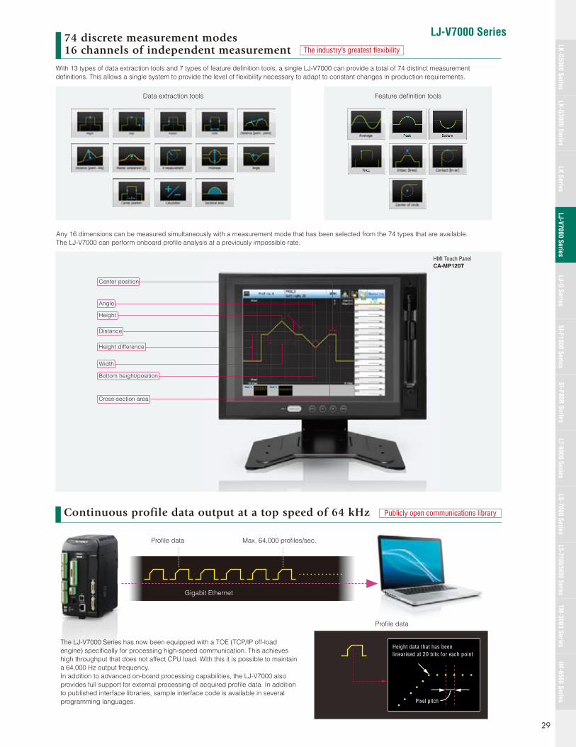
LJ-V7000 Series
Publicly open communications library
74 discrete measurement modes16 channels of independent measurement The industry’s greatest fl exibility
With 13 types of data extraction tools and 7 types of feature defi nition tools, a single LJ-V7000 can provide a total of 74 distinct measurement
defi nitions. This allows a single system to provide the level of fl exibility necessary to adapt to constant changes in production requirements.
Data extraction tools Feature defi nition tools
Any 16 dimensions can be measured simultaneously with a measurement mode that has been selected from the 74 types that are available.
The LJ-V7000 can perform onboard profi le analysis at a previously impossible rate.
Distance
Height
Angle
Center position
Height difference
Width
Bottom height/position
Cross-section area
The LJ-V7000 Series has now been equipped with a TOE (TCP/IP off-load
engine) specifi cally for processing high-speed communication. This achieves
high throughput that does not affect CPU load. With this it is possible to maintain
a 64,000 Hz output frequency.
In addition to advanced on-board processing capabilities, the LJ-V7000 also
provides full support for external processing of acquired profi le data. In addition
to published interface libraries, sample interface code is available in several
programming languages.
Gigabit Ethernet
Profi le data
Profi le data Max. 64,000 profi les/sec.
Pixel pitch
Height data that has been linearised at 20 bits for each point
Continuous profile data output at a top speed of 64 kHz
HMI Touch PanelCA-MP120T
29
LK-G5000 SeriesLK-G3000 Series
LJ-G SeriesSI-F1000 Series
SI-F80R SeriesLS-7000 Series
LS-3100/5000 SeriesTM
-3000 SeriesIM
-6500 SeriesLK Series
LJ-V7000 SeriesLT-9000 Series

Specifi cations
• The rating for NPN open-collector output is up to 50 mA (40 V or less), residual voltage of up to 1 V• The rating for PNP open-collector output is up to 50 mA (30 V or less), residual voltage of up to 1 V• The rating for non-voltage input is up to 1 V for ON voltage and up to 0.6 mA for OFF current• The rating for voltage input is a maximum input voltage of 26.4 V, a minimum ON voltage of 10.8 V, and up to 0.6 mA for OFF current
*1 Connections through a hub are not covered under warranty.*2 Only Japanese and English are currently supported. Other languages are expected to receive support in the near future.• Windows is a registered trademark of the Microsoft Corporation, U.S.A.• Core is a registered trademark of the Intel Corporation.
Model LJ-V7001 LJ-V7001P
No. of connectable sensors Max. 2 units
DisplayMinimum display unit 0.1 μm 0.0004 Mil, 0.00001 mm2, 0.01°
Maximum display range ±99999.9 mm 3937.00", ±999999 mm2
Input terminal block
Laser remote interlock input No-voltage input
Encoder input NPN open-collector output, voltage output (5 V/12 V/24 V), and line-driver output all supported
Trigger inputs
Non-voltage input Voltage input
Timing 1, 2 input
Auto-zero1, 2 input
Reset 1, 2 input
Start measurement/stop input
Start storage/stop input
Clear memory input
Laser OFF input
Programme switch input No-voltage input x 4 inputs Voltage input x 4 inputs
Output terminal block
Analogue voltage output ±10 V x 2 outputs, Output impedance: 100 Ω
OUT comparator output NPN open collector output x 12 outputs(Can freely assign 16 OUTs x 3 stage judgment results)
PNP open collector output x 12 outputs(Can freely assign 16 OUTs x 3 stage judgment results)
Strobe output
NPN open collector output PNP open collector outputDisable trigger output
Memory FULL output
Ready output
Error output NPN open collector output (N.C.) PNP open collector output (N.C.)
Ethernet interface 1000BASE-T/100BASE-TX
USB Interface USB 2.0 high speed compliant (USB 1.1 Full-SPEED compatible)
RS-232C interface Measurement data output and control I/O (Can select a baud rate of up to 115,200 bits/s)
RatingVoltage Includes 24 VDC ±10% ripple (P-P)
Maximum current consumption 1.3 A or less when connected to 1 head/ 1.9 A or less when connected to 2 heads
Environmental resistance
Operating ambient temperature 0 to +50°C 32 to 122°F
Operating ambient humidity 20 to 85% RH (No condensation)
Weight Approx. 1500 g
Model LJ-VM100
Monitor output Analog RGB XGA (1024 × 768)Touch panel monitor (CA-MP120T), specialized connector included
Voltage Supplied from the controller
Power consumption 2.5 W or less
Environmental resistance
Operating ambient temperature 0 to +50°C 32 to 122°F
Operating ambient humidity 20 to 85% RH (No condensation)
Weight Approx. 400 g
Item Minimum system requirements
PC InterfaceEthernet*1 1000BASE-T/100BASE-TX
USB*1 USB 2.0 high speed compliant (USB 1.1 Full-SPEED compatible)
Supported OSWindows7 (Home Premium, Professional, Ultimate)Windows Vista (Home Basic, Home Premium, Business, Ultimate)Windows XP (SP2 or later) (Home Edition, Professional Edition)
Supported languages*2 Japanese, English, German, French, Simplifi ed Chinese, Traditional Chinese
CPU Core i3 2.3 GHz or higher
Memory capacity 2 GB or more
2D cache memory 2 MB or more
Free space on hard disk 10 GB or more
Display resolution XGA (1024 x 768) or higher
Weight Approx. 400 g
Controller
Display output unit
LJ-H2 (LJ-Navigator 2) operation system environment
LJ-V7000 Series
30
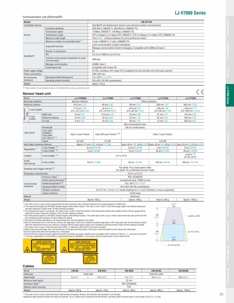
LJ-V7000 Series
Model CB-B3 CB-B10 CB-B5E CB-B10E CB-B20E
Cable type Head cable Extension cableCable length 3 m 9.8' 10 m 32.8' 5 m 16.4' 10 m 32.8' 20 m 65.6'Minimum bend radius 22 mmEnclosure rating*1 IP67 (IEC60529)Material (outer covering) PVCWeight Approx. 250 g Approx. 750 g Approx. 400 g Approx. 800 g Approx. 1500 g
*1 This value is from a case in which the sensor head has been connected. However, the controller side connector is not included.• Regarding cable extension between the head and controller: Up to 2 cables can be connected with the CB-BxxE, and these cables should be kept to a total length of 30 m 98.4' or less.
Cables
*1 This value is from a case in which measurement has been performed with a reference distance at an average frequency of 4096 times.*2 The measurement targets are KEYENCE standard targets (white diffuse objects). This value is from a case in which the average height of the default setting area
has been measured in height mode. All other settings are default.*3 The measurement target is a pin gauge. This value is from a case in which the position of the intersection between the rounded surface of the pin gauge and the
edge level has been measured in position mode. All other settings are default.*4 The measurement targets are KEYENCE standard targets (white diffused objects). The profi le data is from a case in which measurement has been performed with
64x smoothing and 8x averaging. All other settings are default.*5 The linearity will differ depending on the measurement area. (See the diagram on the right.)*6 When the measurement area is at its minimum, binning is ON, image capture mode is set to standard, and parallel image capture is ON in high-speed mode. All other settings are default.
When the measurement area is at its minimum, binning is ON and image capture mode is set to standard in advanced function mode. All other settings are default.*7 This value is from a case in which the head cable (CB-B*) or extension cable (CB-B*E) has been connected.*8 When measuring white paper, this is the illuminance for the light-receiving surface of the sensor head when light has been shined onto white paper.*9 Use the sensor head after fi rst mounting it on a metal plate.*10 Viewing the laser output with certain optical instruments (for example, eye loupes, magnifi ers and microscopes) within a distance of 100 mm 3.94” may pose an eye hazard.*11 The laser classifi cation for FDA (CDRH) is implemented based on IEC60825-1 in accordance with the requirements of Laser Notice No.50.
Model LJ-V7060K LJ-V7060 LJ-V7080 LJ-V7200 LJ-V7300
Mounting conditions Specular refl ection Diffuse refl ectionReference distance 54.6 mm 2.15" 60 mm 2.36" 80 mm 3.15" 200 mm 7.87" 300 mm 11.81"
Mea
sure
men
t ra
nge
Z-axis (height) ±7.6 mm 2.99"(F.S.=15.2 mm 0.60")
±8 mm 0.31"(F.S.=16 mm 0.63")
±23 mm 0.91"(F.S.=46 mm 1.81")
±48 mm 1.89"(F.S.=96 mm 3.78")
±145 mm 5.71"(F.S.=290 mm 11.42")
X-axis (width)
NEAR side 8 mm 0.31" 13.5 mm 0.53" 25 mm 0.98" 51 mm 2.01" 110 mm 4.33"Reference distance 14 mm 0.55" 15 mm 0.59" 32 mm 1.26" 62 mm 2.44" 180 mm 7.09"Far side 8 mm 0.31" 15 mm 0.59" 39 mm 1.54" 73 mm 2.87" 240 mm 9.45"
Light source
Blue semiconductor laserWavelength 405 nm (visible beam)Laser classIEC60825-1FDA(CDRH) Part 1040.10*11
Class 2 Laser Product Class 2M Laser Product*10 Class 2 Laser Product
Output 4.8 mW 10 mW 4.8 mWSpot shape (reference distance) Approx. 21 mm 0.83" x 45 μm 1.77 Mil Approx. 48 mm 1.89" x 48 μm 1.89 Mil Approx. 90 mm 3.54" x 85 μm 3.35 Mil Approx. 240 mm 9.45" x 610 μm 24.02 Mil
Repeatability*1 Z-axis (height) *2 0.4 μm 0.02 Mil 0.5 μm 0.02 Mil 1 μm 0.04 Mil 5 μm 0.20 MilX-axis (width) *3 5 μm 0.20 Mil 10 μm 0.39 Mil 20 μm 0.79 Mil 60 μm 2.36 Mil
Linearity Z-axis (height) *4 ±0.1% of F.S. ±0.05 to *5
±0.15% of F.S.
Profi leData interval X-axis (width) 20 μm 0.79 Mil 50 μm 1.97 Mil 100 μm 3.94 Mil 300 μm 11.81 Mil
Sampling cycle (trigger interval)*6 Top speed: 16 μs (high-speed mode)Top speed: 32 μs (advanced function mode)
Temperature characteristics 0.01% of F.S./°C
Environmental resistance
Enclosure rating*7 IP67 (IEC60529)Ambient operating illuminance*8 Incandescent lamp: 10000 lux maxAmbient temperature*9 0 to +45°C 32 to 113°FOperating Ambient humidity 20 to 85% RH (No condensation)Vibration resistance 10 to 57 Hz, 1.5 mm 0.06" double amplitude in X, Y, and Z directions, 3 hours respectivelyImpact resistance 15 G/6 msec
Material AluminiumWeight Approx. 450 g Approx. 400 g Approx. 550 g Approx. 1000 g
Sensor head unit
4.33"110
±0.05% of F.S.
7.09"180
9.45"240
1455.71"
1455.71"
±0.1% of F.S.
±0.15% of F.S.
Model CB-EP100
Compatible network EtherNet/IP and displacement sensor’s own protocols (socket communication)
Eternet
Compliant standards IEEE 802.3 (10BASE-T), IEEE 802.3u (100BASE-TX)Transmission speed 10 Mbps (10BASE-T), 100 Mbps (100BASE-TX)Transmission media STP or Category 3 or higher UTP (10BASE-T), STP or Category 5 or higher UTP (100BASE-TX)Maximum cable length 100 m 328.1' (Distance between the unit and Ethernet switch)Maximum number of connectable hubs*1 4 hubs (10BASE-T), 2 hubs (100BASE-TX)
EtherNet/IP
Supported functionsCyclic communication (Implicit messaging)Message communication (Explicit messaging), Compatible with UCMM and Class 3
Number of connections 64RPI 0.5 ms to 10000 ms (in 0.5 ms)
Tolerable communication bandwidth for cyclic communication 6000 pps
Message communication UCMM, Class 3Conformance test Compatible with Version A9
Power supply voltage 24 VDC, including ±10% ripple (P-P) (supplied from the controller unit of the laser scanner)Power consumption 2400 mW max.
Environmental resistance
Operating ambient temperature 0 to +50°C 0 to 122°FOperating ambient humidity 20 to 85% RH (No condensation)
Weight Approx. 470 g
*1 The number of connectable hubs is not limited when using a switching hub.
Communication unit (Ethernet/IP)
31
LK-G5000 SeriesLK-G3000 Series
LJ-G SeriesSI-F1000 Series
SI-F80R SeriesLS-7000 Series
LS-3100/5000 SeriesTM
-3000 SeriesIM
-6500 SeriesLK Series
LJ-V7000 SeriesLT-9000 Series
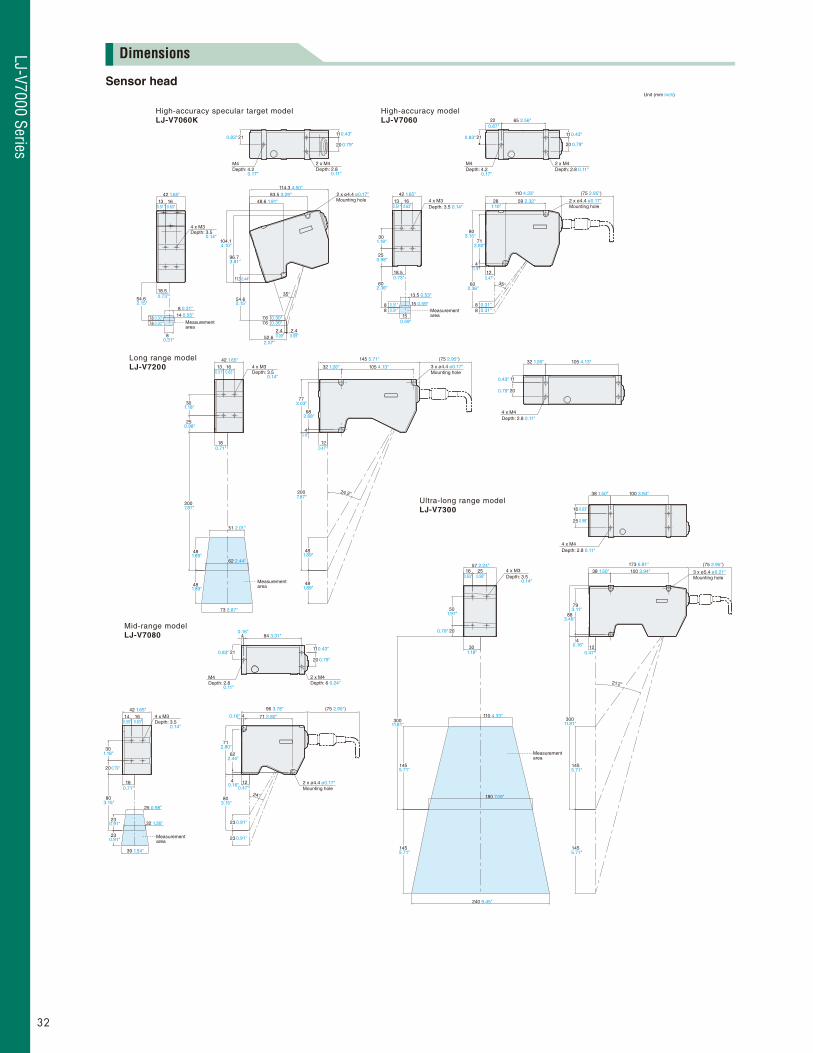
Unit (mm inch)
High-accuracy specular target modelLJ-V7060K
High-accuracy modelLJ-V7060
42 1.65"13 16 4 x M3
Depth: 3.5 0.14"
13.5 0.53"
15 0.59"
15
88
18.5
30
25
60
2 x M4Depth: 2.8 0.11"
M4Depth: 4.2
21
22 65 2.56"
11
20
2 x ø4.4 ø0.17"Mounting hole
28
110 4.33" (75 2.95")
59 2.32"
4
88
12
35°
80
60
Mid-range modelLJ-V7080 4 84 3.31"
2 x M4Depth: 6 0.24"
M4Depth: 2.8
2111
20
71 2.80"
96 3.78" (75 2.95")
12
24°
2 x ø4.4 ø0.17"Mounting hole
4
4
62
71
80
23
23
Depth: 3.514 16
42 1.65"4 x M3
18
25 0.98"
32 1.26"
39 1.54"
23
80
20
30
23
Long range modelLJ-V7200
4 x M4Depth: 2.8 0.11"
32 1.26" 105 4.13"
20
11
Ultra-long range modelLJ-V7300
4 x M3Depth: 3.5
16 2557 2.24"
30
110 4.33"
180 7.09"
240 9.45"
50
20
300
145
145
3 x ø5.4 ø0.21"Mounting hole
38 1.50" 100 3.94"173 6.81"
124
21.2°
300
145
145
79
88
38 1.50" 100 3.94"
4 x M4Depth: 2.8 0.11"
16
25
Measurement area
Measurement area
Measurement area
Depth: 3.54 x M3
7.6 0.30"7.6 0.30"
814
8
18.5
13 16
42 1.65"
54.6
210.83"
0.17"
0.14"
0.73"
0.31"
0.31"0.55"
2.15"
0.43"0.83"
0.87"
1.10"
3.15"
2.36"
0.31"0.31"
0.79"
0.43"
0.17"
0.79"
0.11"
0.51" 0.63"
11
20
2 x M4Depth: 2.8
M4Depth: 4.2
35°
114.3 4.50"83.5 3.29"
52.6
48.6 1.91"
7.67.6
2.4 2.4
Mounting hole2 x ø4.4 ø0.17"
96.7
11.3
54.6
(75 2.95")
Measurement area
0.51" 0.63"
104.14.10"
3.81"
0.44"
2.15"
0.30"
0.31"0.31"
0.30"
0.09" 0.09"2.07"
1.18"
0.98"
2.36"
0.59"
0.73"
712.80"
0.16"
0.47"
0.43"
0.79"
4
12
24.2°
3 x ø4.4 ø0.17"32 1.26" 105 4.13"
145 5.71" (75 2.95")
Mounting hole
68
77
200
48
48
73 2.87"
18
51 2.01"
62 2.44"
4 x M3Depth: 3.5
13 16
42 1.65"
30
25
200
48
48Measurement area
0.51" 0.63"
1.18"
0.98"
7.87"
1.89"
1.89"
0.71"
0.14"
3.03"
2.68"
7.87"
1.89"
1.89"
0.16"
0.47"
0.55" 0.63"0.14"
0.71"
0.79"
1.18"
3.15"
0.91"
0.91"
0.16"
0.16"
0.16"0.47"
3.15"
0.91"
0.91"
0.83"
0.11"
0.43"
0.79"
2.80"
2.44"
0.63"
0.98"
0.63" 0.98"0.14"
1.18"
0.79"
1.97"
11.81"
5.71"
5.71"
3.11"
3.46"
0.16"
0.47"
11.81"
5.71"
5.71"
Dimensions
Sensor head
LJ-V7000 Series
32
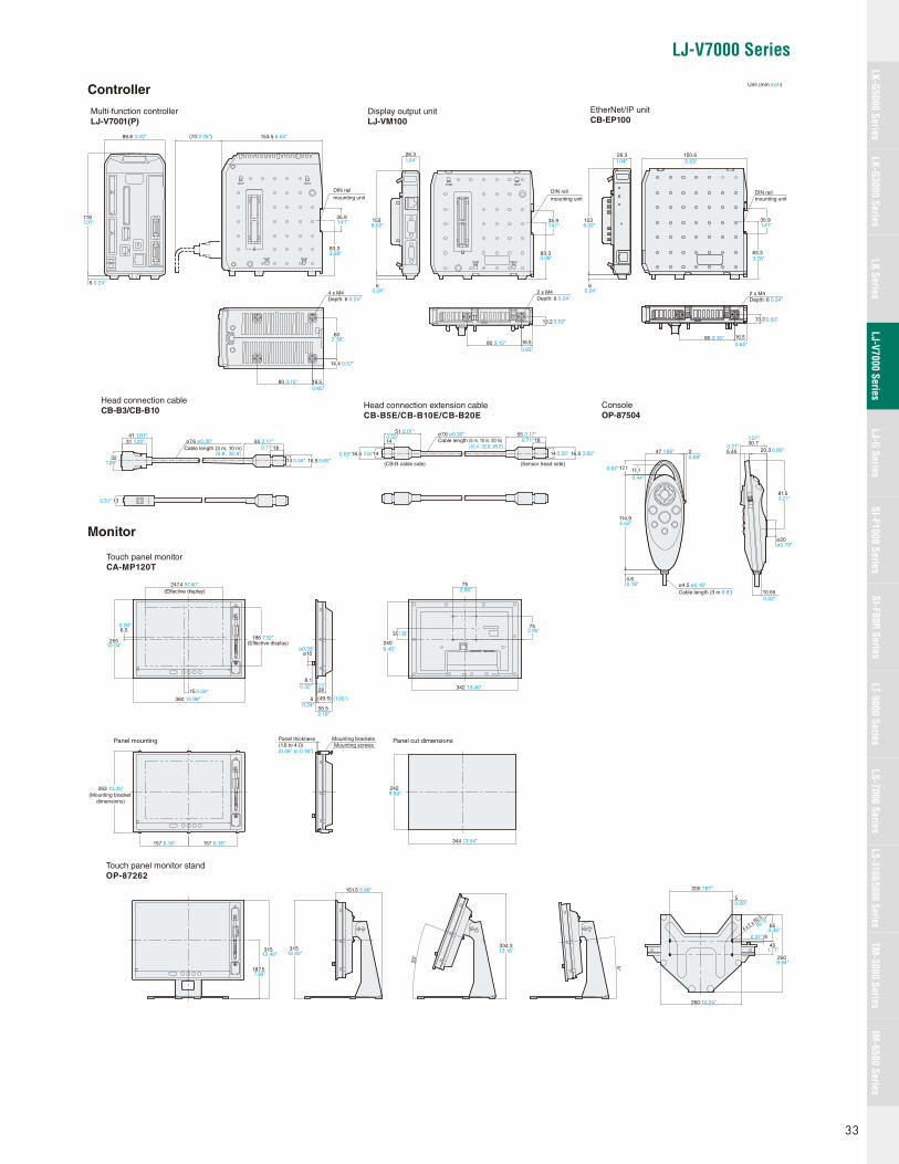
LJ-V7000 Series
EtherNet/IP unitCB-EP100
DIN rail mounting unit
35.9
150.626.3
83.3
2 x M4
16.5
13.2
60
14.4
4 x M4Depth: 6 0.24"
80 3.15" 16.5
26.3
6
153
DIN railmounting unit
35.9
83.3
Depth: 6 0.24" Depth: 6 0.24"2 x M4
80 3.15"80 3.15"
16.5
13.2
247 1.85"
Cable length (3 m 9.8')ø4.5 ø0.18"
114.9
4.6
17.1 11.1
30.720.3
10.55
5.45
81.5
ø20
41 1.61"55 2.17"ø7.6 ø0.30"
Cable length (3 m, 10 m) 1831 1.22"
14 16.532
13
55 2.17"ø7.6 ø0.30"Cable length (5 m, 10 m, 20 m) 1814
51 2.01"
(CB-B cable side) (Sensor head side)
1416.5 14 16.5
ConsoleOP-87504
Head connection cableCB-B3/CB-B10
Touch panel monitor standOP-87262
Head connection extension cableCB-B5E/CB-B10E/CB-B20E
Multi-function controllerLJ-V7001(P)
Display output unitLJ-VM100
Touch panel monitorCA-MP120T
Panel mounting
263 10.35"(Mounting bracket
dimensions)
157 6.18" 157 6.18"
Panel thickness(1.6 to 4.0)
Mounting bracketsMounting screws
8.1
28
(49.5)6
55.5
ø10
35
2409.45"
1.38"
75
75
342 13.46"
Panel cut dimensions
242
344 13.54"
6.5
255
247.4 97.40"(Effective display)
(Effective display)186 7.32"
15
360 14.96"
187.5
315
8
45
85
250
4 x 2 x R
2.5
R0.10"
260 10.24"
200 7.87"
5
315
151.5 5.96"
20°
334.3
5°
88.8 3.50"
178
6 0.24"
7.01"
153.5 6.04"(70 2.76")
DIN railmounting unit
2.36"
0.57"
0.65"
1.04" 1.04" 5.93"
6.02"1536.02"
0.24"6
0.24"
1.41" 1.41"
3.28" 3.28"
0.65"0.65"
0.52" 0.52"
0.08"
0.44"
0.67"
4.52"
0.18"
0.42"
ø0.79"
3.21"
0.80"
1.21"
0.21"
1.26"
(9.8', 32.8')0.71"
0.65"0.55"
0.51"
0.55"
0.55"0.65"
(16.4', 32.8', 65.6')0.71"
0.55" 0.65"
0.26"
10.04"
0.59"
ø0.39"
0.32"
0.24"
1.10"
(1.95")
2.19"
2.95"
2.95"
(0.06" to 0.16")
9.53"
12.40" 12.40"
7.38"
0.20"
3.35"0.31"
1.77"
9.84"
13.16"
35.91.41"
83.33.28"
Unit (mm inch)
33
LK-G5000 SeriesLK-G3000 Series
LJ-G SeriesSI-F1000 Series
SI-F80R SeriesLS-7000 Series
LS-3100/5000 SeriesTM
-3000 SeriesIM
-6500 SeriesLK Series
LJ-V7000 SeriesLT-9000 Series
Controller
Monitor

High-Accuracy 2D Laser Displacement Sensor
The LJ-G Series provides 8-point simultaneous measurement in various
measuring modes (height, width, height difference, angle, profi le, cross-
section area, etc.). Desired measuring points can be specifi ed relative to a
profi le waveform. Furthermore, the LJ-G Series provides outputs of individual
measured values and upper/lower tolerance comparator outputs.
LJ-G Series
Features Linearity of ±0.1% of F.S. High-speed sampling Simultaneous measurement/judgement of up to 8 features Stable measurement for all targets
Expert Engineering SitesA new site with answers to all of your diffi cult measurement application questions
www.keyence.com
8-point simultaneous measurement/judgment
Measurement menus Useful Adjustment Functions
Measurements
Peak height Average height
Width/Position Angle/Intersection
Bottom height Gap
Section area Profile comparison
Best in its class
POSITION ADJUSTMENT FUNCTIONAfter the adjustment, the LJ-G Series can provide
stable measurements though the targets are not
neatly arranged or positioned.
Displacement of target
Measuring range
Measuring range
Adj
ustm
ent
Since the workpiece is not in the measuring range, a precise measurement cannot be carried out.
The measuring range moves according to the displacement of the workpiece for precise measurement.
HEIGHT Peak
Average
Bottom
WIDTH/POSITION Position (XZ coordinate)
Width
Measures height in a specifi ed range.
Measures width/position with a specifi ed condition.
STEP Measured point
Reference point
Step
SECTION AREA
Reference surface
Section areaDetermines the height difference between a measured point and the reference point.
Measures the area on the basis of the reference surface.
ANGLE/INTERSECTION
Angle
Position of intersection (XZ coordinate)
PROFILE COMPARISON Master profile
Measurement value
Measures the angle or intersection of detected lines.
Compares the target profi le with the master profi le to measure the largest difference.
34
LJ-G Series
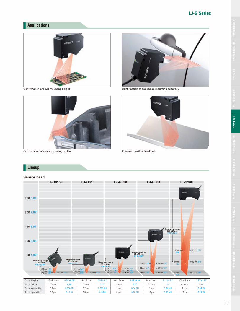
LJ-G Series
Applications
Lineup
Confi rmation of PCB mounting height
Confi rmation of sealant coating profi le
Confi rmation of door/hood mounting accuracy
Pre-weld position feedback
Z-axis (Height) 15 ±2.3 mm 0.59"±0.09" 15 ±2.6 mm 0.59"±0.1" 30 ±10 mm 1.18"±0.39" 80 ±23 mm 3.15"±0.91" 200 ±48 mm 7.87"±1.89"
X-axis (Width) 7 mm 0.28" 7 mm 0.28" 22 mm 0.87" 32 mm 1.26" 62 mm 2.44"
Z-axis repeatability 0.2 μm 0.008 Mil 0.2 μm 0.008 Mil 1 μm 0.04 Mil 1 μm 0.04 Mil 2 μm 0.08 Mil
X-axis repeatability 2.5 μm 0.10 Mil 2.5 μm 0.10 Mil 5 μm 0.20 Mil 10 μm 0.39 Mil 20 μm 0.78 Mil
LJ-G030LJ-G015LJ-G015K LJ-G080 LJ-G200
50 1.97"
100 3.94"
150 5.91"
200 7.87"
250 9.84"
20 mm 0.79"30 mm 1.18"40 mm 1.57"
w: 20 mm 0.79"w: 22 mm 0.87"w: 25 mm 0.98"
Measuring range30 ±10 mm1.18"±0.39"
12.4 mm 0.49"15 mm 0.59"
17.6 mm 0.69"
12.7 mm 0.50"15 mm 0.59"
17.3 mm 0.68" w: 7 mm 0.28"w: 7 mm 0.28"
Measuring range15 ±2.6 mm0.59"±0.1"
Measuring range15 ±2.3 mm0.59"±0.09"
Measuring range80 ±23 mm3.15"±0.91"
57 mm 2.24"
80 mm 3.15"
103 mm 4.06"
w: 25 mm 0.98"
w: 32 mm 1.26"
w: 39 mm 1.54"
Measuring range200 ±48 mm7.87"±1.89"
152 mm 5.98"
w: 51 mm 2.01"
w: 62 mm 2.44"
w: 73 mm 2.87"
200 mm 7.87"
248 mm 9.76"
Sensor head
35
LK-G5000 SeriesLK-G3000 Series
LJ-G SeriesSI-F1000 Series
SI-F80R SeriesLS-7000 Series
LS-3100/5000 SeriesTM
-3000 SeriesIM
-6500 SeriesLK Series
LJ-V7000 SeriesLT-9000 Series

E3-CMOS providing ultra-wide dynamic range
ASAP (Automatic Sensitivity Adjustment by Pixel)
High capacity memory for saving data
The E3-CMOS provides ultra-wide dynamic range which is approximately 300 times wider than conventional modes. The LJ-G Series enables target
profi le measurement and the measurement of different target materials, such as black rubber (low refl ected light intensity) and refl ective metal (high
refl ected light intensity).* E3-CMOS sensor: Enhanced Eye Emulation CMOS image sensor
This function adjusts the sensitivity and laser power of the E3-CMOS to obtain suitable waveform data for each
measurement position that has a different refl ectance. The obtained data is merged as a single measurement profi le.
High capacity memory is built into the controller. A memory card slot is included to store the production records of mass-produced products.
NEW
First in the world
Best in its class
Profile measurementLight intensityLaser light reflection
Target object
Light-receiving sensitivity range
Out of measurement
Light-receiving sensitivity range is 300 times larger.
Sensor head
The reflected light intensity changes according to the shape, color, and material of the target.
Traditional light receiving elements do not have enough sensitivity to cover the entire range.
The edges of the profile are not measured because the light intensity is far less on the angled surfaces than the flat surfaces.
The dynamic range is 300 times larger than the conventional model and covers the entire range.
The entire profile is measured.
Conventional
E3-CMOS
High
Low
High
Low
Handling many product typesThe built-in memory can store up to 16 programs. When the memory card
is used, up to 160 programs can be stored to handle various product
types.
Program setting Profi le saving Data storage
Internal memory 16 1024 x 2 65536 x 8
CF(1GB) 160 1024 x 300 65536 x 3200
Profi le savingFor analyzing NG records or production history.
1024 profi lesHandles 160 types
OK17.221Program01
OUT01
[mm]
MemoryCard
OUT1 GOOUT2 GOOUT3 GOOUT4 GOOUT5 GOOUT6 GOOUT7 GOOUT8 GOALL OUT
-30.000mm
30.000mm
-20.000mm 20.000mm
X : [ 5.000mm/div]X : [ 10.000mm/div]
5 ms
5 ms
GO
ZEROMeasure
Trg interval
Process time
OK15.982Program01
OUT01
[mm]
MemoryCard
OUT1 GOOUT2 GOOUT3 GOOUT4 GOOUT5 GOOUT6 GOOUT7 GOOUT8 GOALL OUT
-30.000mm
30.000mm
-20.000mm 20.000mm
X : [ 5.000mm/div]X : [ 10.000mm/div]
5 ms
5 ms
GO
ZEROMeasure
Trg interval
Process time
OK10.121Program01
OUT01
[mm]
MemoryCard
OUT1 GOOUT2 GOOUT3 GOOUT4 GOOUT5 GOOUT6 GOOUT7 GOOUT8 GOALL OUT
-30.000mm
30.000mm
-20.000mm 20.000mm
X : [ 5.000mm/div]X : [ 10.000mm/div]
5 ms
5 ms
GO
ZEROMeasure
Trg interval
Process time
OK16.382Program01
OUT01
[mm]
MemoryCard
OUT1 GOOUT2 GOOUT3 GOOUT4 GOOUT5 GOOUT6 GOOUT7 GOOUT8 GOALL OUT
-30.000mm
30.000mm
-20.000mm 20.000mm
X : [ 5.000mm/div]X : [ 10.000mm/div]
5 ms
5 ms
GO
ZEROMeasure
Trg interval
Process time
OK14.268Program01
OUT01
[mm]
MemoryCard
OUT1 GOOUT2 GOOUT3 GOOUT4 GOOUT5 GOOUT6 GOOUT7 GOOUT8 GOALL OUT
-30.000mm
30.000mm
-20.000mm 20.000mm
X : [ 5.000mm/div]X : [ 10.000mm/div]
5 ms
5 ms
GO
ZEROMeasure
Trg interval
Process time
OK15.393Program01
OUT01
[mm]
MemoryCard
OUT1 GOOUT2 GOOUT3 GOOUT4 GOOUT5 GOOUT6 GOOUT7 GOOUT8 GOALL OUT
-30.000mm
30.000mm
-20.000mm 20.000mm
X : [ 5.000mm/div]X : [ 10.000mm/div]
5 ms
5 ms
GO
ZEROMeasure
Trg interval
Process time
Dynamic range 6000x
Target with an extremely different
refl ectance at each position
Sensitivity: Small Sensitivity: Medium Sensitivity: Largest Measurement profi le
36
LJ-G Series
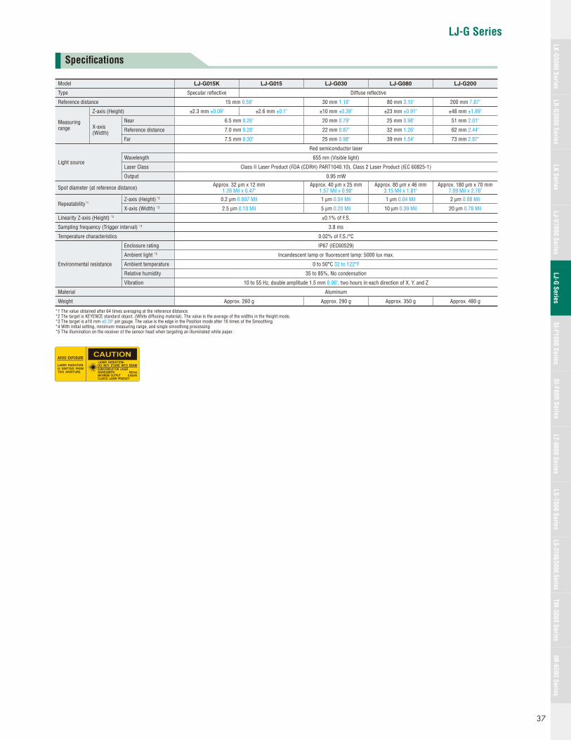
LJ-G Series
Model LJ-G015K LJ-G015 LJ-G030 LJ-G080 LJ-G200
Type Specular refl ective Diffuse refl ective
Reference distance 15 mm 0.59" 30 mm 1.18" 80 mm 3.15" 200 mm 7.87"
Measuring range
Z-axis (Height) ±2.3 mm ±0.09" ±2.6 mm ±0.1" ±10 mm ±0.39" ±23 mm ±0.91" ±48 mm ±1.89"
X-axis (Width)
Near 6.5 mm 0.26" 20 mm 0.79" 25 mm 0.98" 51 mm 2.01"
Reference distance 7.0 mm 0.28" 22 mm 0.87" 32 mm 1.26" 62 mm 2.44"
Far 7.5 mm 0.30" 25 mm 0.98" 39 mm 1.54" 73 mm 2.87"
Light source
Red semiconductor laser
Wavelength 655 nm (Visible light)
Laser Class Class II Laser Product (FDA (CDRH) PART1040.10), Class 2 Laser Product (IEC 60825-1)
Output 0.95 mW
Spot diameter (at reference distance) Approx. 32 μm x 12 mm 1.26 Mil x 0.47"
Approx. 40 μm x 25 mm 1.57 Mil x 0.98"
Approx. 80 μm x 46 mm 3.15 Mil x 1.81"
Approx. 180 μm x 70 mm 7.09 Mil x 2.76"
Repeatability*1Z-axis (Height) *2 0.2 μm 0.007 Mil 1 μm 0.04 Mil 1 μm 0.04 Mil 2 μm 0.08 Mil
X-axis (Width) *3 2.5 μm 0.10 Mil 5 μm 0.20 Mil 10 μm 0.39 Mil 20 μm 0.78 Mil
Linearity Z-axis (Height) *2 ±0.1% of F.S.
Sampling frequency (Trigger interval) *4 3.8 ms
Temperature characteristics 0.02% of F.S./°C
Environmental resistance
Enclosure rating IP67 (IEC60529)
Ambient light *5 Incandescent lamp or fl uorescent lamp: 5000 lux max.
Ambient temperature 0 to 50°C 32 to 122°F
Relative humidity 35 to 85%, No condensation
Vibration 10 to 55 Hz, double amplitude 1.5 mm 0.06", two hours in each direction of X, Y, and Z
Material Aluminum
Weight Approx. 260 g Approx. 290 g Approx. 350 g Approx. 480 g
*1 The value obtained after 64 times averaging at the reference distance.*2 The target is KEYENCE standard object. (White diffusing material). The value is the average of the widths in the Height mode.*3 The target is ø10 mm ø0.39" pin gauge. The value is the edge in the Position mode after 16 times of the Smoothing.*4 With initial setting, minimum measuring range, and single smoothing processing*5 The illumination on the receiver of the sensor head when targeting an illuminated white paper.
Specifi cations
37
LK-G5000 SeriesLK-G3000 Series
LJ-G SeriesSI-F1000 Series
SI-F80R SeriesLS-7000 Series
LS-3100/5000 SeriesTM
-3000 SeriesIM
-6500 SeriesLK Series
LJ-V7000 SeriesLT-9000 Series

38
LJ-G Series
Hardware environment for the LJ-H1W (LJ-Navigator)
Model LJ-H1W
CPU Pentium III, 400 MHz or higher
Supported OS Windows 7*1/Windows Vista*2/Windows XP Professional Edition/Home Edition/Windows 2000 Professional
Memory capacity 128 MB or more
Display XGA (1024 x 768 pixels) or greater, 256 colors or greater
Hard disk space 30 MB or more
Interface*3 Includes one of the following:USB 2.0/1.1*4, Ethernet*5, RS-232C (Serial port)
• Windows is a registered trademark of Microsoft Corporation of America.• Pentium is a registered trademark of Intel Corporation.*1 Home Premium, Professional and Ultimate editions are supported.*2 Ultimate, Business, Home Premium, Home Basic editions are supported. For Windows Vista, Ver. 1.6 and later versions are supported.*3 Select one for communication. Multiple interfaces cannot be used for communication at the same time.*4 Operations are not guaranteed when connected through a USB hub.*5 Operations are not guaranteed when connected through a router or a LAN connection.
Controller
Model LJ-G5001 LJ-G5001P
Sensor head compatibility Compatible
Number of connectable sensors 2 units max.
DisplayMinimum display unit 0.1 μm *1, 0.001 mm2, 0.01° (Inch mode : 0.01 Mil, 0.00001 inch)
Maximum display range ±99999.9 mm, ±999999 mm2, ±99999.9° (Inch mode : ±9999.99 Mil, ±999.999 inch)
Inputterminalblock
Laser remote interlock input Non-voltage input
Trigger input For sensor head A, non-voltage input For sensor head A, voltage input
Timing 1 inputNon-voltage input Voltage inputAuto-zero 1 input
Reset input
Outputterminalblock
Analog voltage output ±10 V x 2 outputs, output impedance: 100 Ω
Total judgment output NPN open-collector output PNP open-collector output
Error output NPN open-collector output (N.C.) PNP open-collector output (N.C.)
Process output NPN open-collector output PNP open-collector output
Trigger input enable outputFor sensor head A, NPN open-collector output For sensor head A, PNP open-collector output
Adjusted error output
Expansionconnector
Timing 2 inputNon-voltage input Voltage input
Auto-zero 2 input
Trigger input For sensor head B, non-voltage input For sensor head B, voltage input
Program switching input Non-voltage input, 4 inputs Voltage input, 4 inputs
Memory card save input Non-voltage input Voltage input
Laser-Off input For sensor head A/B, non-voltage input For sensor head A/B, voltage input
Judgment/Binary output *23-level judgment output: OUT1 to OUT8, total judgment outputBinary output: OUT1 to OUT8 measured data output (21 bits)
NPN open-collector output
3-level judgment output: OUT1 to OUT8, total judgment outputBinary output: OUT1 to OUT8 measured data output (21 bits)
PNP open-collector output
Strobe output NPN open-collector output PNP open-collector output
Trigger input enable outputFor sensor head B, NPN open-collector output For sensor head B, PNP open-collector output
Adjusted error output
Analog RGB monitor output SVGA (800 x 600 pixels)
RS-232C interface Measured data output and control input/output (Maximum baud rate: 115200 bps, selectable)
USB interface In conformity with USB Revision 2.0 HI-SPEED (USB 1.1 Full-SPEED compatible)
Ethernet interface 100BASE-TX/10BASE-T
Memory card Compatible with NR-M32 (32 MB), GR-M256 (256MB), and NR-M1G (1GB). (with FAT32)
Major functions
Sensor heads calculation, Profi le adjustment, Filter, Smoothing, Averaging,Position adjustment, OUT name change, Measurement mode selection
(Height, position, gap, width, center position, section area, intersection, angle, profi le comparison, profi le tracking),Scaling, Average, Measurement, Measured value alarm, Tolerance setting, Auto-zero, Storage (data/profi le),
Memory card saving, Program memory, Trigger mode change, Mutual interference prevention, Measuring range change,Calibration, Laser light adjustment, Sampling time setting, Mask, Profi le alarm setting, Inclination adjustment, Height adjustment,
Display language switch, Setting support software connection, Trigger pitch/Measuring time display, etc.
RatingsPower supply voltage 24 VDC ±10%, Ripple: 10% (P to P) or less
Current consumption 800 mA or less with 1 sensor head/1 A or less with two sensor heads
Environmentalresistance
Ambient temperature 0 to 50°C 32 to 122°F
Relative humidity 35 to 85%, No condensation
Weight Approx. 1050 g
*1 When LJ-G015 or LJ-G015K is connected only. When other sensor heads are connected, the minimum display unit is 1 μm.*2 Time-sharing output of judgment results or binary measured data.
The rating of the NPN open-collector output: 50 mA max. (30 V max.), residual voltage of 1 V max. The rating of the PNP open-collector output: 50 mA max. (30 V max.), residual voltage of 1 V max. The rating of the non-voltage input: 1 V or less ON voltage, 0.6 mA or less OFF current (Trigger input terminal: 1 V or less ON voltage, 1.0 mA or less OFF current) The rating of the voltage input: 26.4 V maximum rating, 10.8 V or less ON voltage, 0.6 mA or less OFF current (Trigger input terminal: 26.4 V maximum rating, 10.8 V or less ON voltage, 1.0 mA or less OFF current)
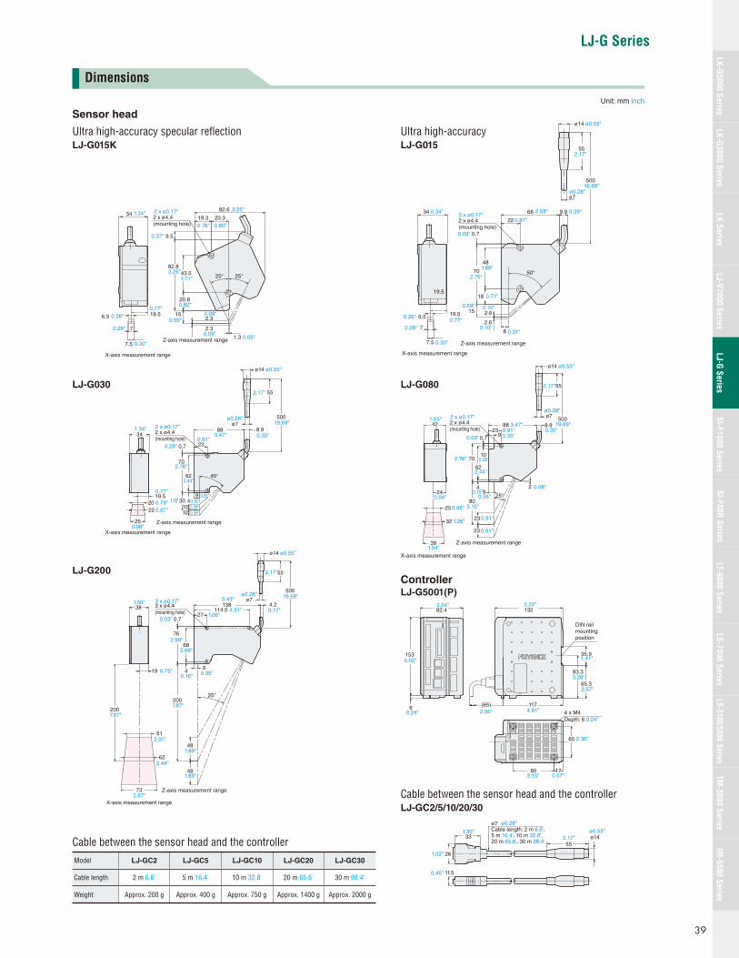
LJ-G Series
34
19.5
7.5
7
6.5
82.6
20.319.3
1.3
2.315
20.8
43.5
0.59"
0.82"
0.09"
0.09"
1.71"
82.8
9.5
3.26"
0.37"
2.3
25° 25°
2 x ø4.4(mounting hole)
3.25"
0.05"
0.76" 0.80"
2 x ø0.17"1.34"
0.77"0.26"
0.30"
0.28"
X-axis measurement range
Z-axis measurement range
18
48
8
15
70
0.7
2.6
2.6
500
55
ø14 ø0.55"
ø7
9.968
22
19.5
7.5
7
6.5 19.5
34
50°
0.03"
2.76"
1.89"
0.71"
0.59" 0.10"
0.10"
2 x ø4.4(mounting hole)
0.34" 2.68" 0.39"
0.87"
0.26"
0.28"
0.30"
0.31"
0.77"
2 x ø0.17"
ø0.28"16.69"
2.17"
X-axis measurement range
Z-axis measurement range
8.9
230.7
62
30 49
1010
45°
55
2019.5
22
1.34"34
X-axis measurement range
Z-axis measurement range25
ø14 ø0.55"
ø7ø0.28"
0.28"0.91"
2 x ø4.4(mounting hole)
2 x ø0.17"
2.44"
0.77"
0.79"0.87"
0.98"
0.35"0.16"0.39"0.39"
1.18"
19.69"
0.35"
500
2.17"
883.47"
702.76"
1.65"42
25
32
39
2 x ø4.4(mounting hole)
8.923
90.7
10
62
70
4
80
23
23
25°9
2
ø14 ø0.55"
55
500ø7
24
X-axis measurement range
Z-axis measurement range
2 x ø0.17"
0.94"
0.98"
1.26"
1.54"
0.91"
0.91"
3.15"
2.76"
2.44"
0.39"
0.03" 0.35"0.91" 0.35"
ø0.28"
0.08"
2.17"
19.69"
0.35"0.16"
88 3.47"
0.03"
2.68"
19.69"
0.17"
0.35"0.16"
7.87"
1.89"
1.89"
2.87"
2.44"
2.01"
0.75"
1.06"4.51"
4.2114.5
270.7
68
4 9
20025°
48
48
55
500
19
X-axis measurement range
73
51
62
Z-axis measurement range
ø7ø0.28"
3 x ø4.4(mounting hole)
3 x ø0.17"
ø14 ø0.55"
2.17"
2.99"
1.50"5.43"
38 138
76
2007.87" 4 x M4
Depth: 6 0.24"
6
DIN rail mounting position
35.9
65.3
83.3
117(65)
60
1780
0.24" 2.56"
3.15" 0.67"
2.36"
4.61"
2.57"
3.28"
1.41"
1325.20"
82.43.24"
1536.02"
11.5
ø7Cable length: 2 m 6.6', 5 m 16.4', 10 m 32.8', 20 m 65.6', 30 m 98.4'
ø0.28"
ø14ø0.55"
331.30"
261.02"
0.45"
552.17"
Dimensions
Unit: mm inch
Sensor head
Ultra high-accuracy specular refl ectionLJ-G015K
LJ-G030
LJ-G200
Cable between the sensor head and the controllerModel LJ-GC2 LJ-GC5 LJ-GC10 LJ-GC20 LJ-GC30
Cable length 2 m 6.6' 5 m 16.4' 10 m 32.8' 20 m 65.6' 30 m 98.4'
Weight Approx. 200 g Approx. 400 g Approx. 750 g Approx. 1400 g Approx. 2000 g
LJ-G5001(P)
Ultra high-accuracyLJ-G015
Cable between the sensor head and the controllerLJ-GC2/5/10/20/30
LJ-G080
Controller
39
LK-G5000 SeriesLK-G3000 Series
LJ-G SeriesSI-F1000 Series
SI-F80R SeriesLS-7000 Series
LS-3100/5000 SeriesTM
-3000 SeriesIM
-6500 SeriesLK Series
LJ-V7000 SeriesLT-9000 Series

Micro-Head Spectral-InterferenceLaser Displacement Meter
SI-F1000 Series
Features Resolution of 0.001 μm 0.00004 Mil Micro-head size of ø2 mm ø0.08" Spectral interference method
Expert Engineering SitesA new site with answers to all of your diffi cult measurement application questions
www.keyence.com
Spectral interface method
No heat generation and no noise
Resolution of 1 nm (0.001 μm) Head size of ø2 mm
Advantages of the optical fi ber head structureThe measurement head consists of only optical fi bers and lenses, with no electronic parts.
High resolution of 1 nm (0.001 μm) has been realized by the development
of new principles and the application of sophisticated controllers. This
resolution can fully respond to a variety of needs for high accuracy.
The simple fi beroptic structure for the
measurement head has allowed KEYENCE
to develop the world's smallest sensor
head without any heat generation problems
associated with compact electronics.
In addition as the sensor head has no
electronic components, it is immune to
electromagnetic noise.
Development of a new principle can meet incompatible needs for small size with high accuracy that was previously impossible.
Small size, light weight, and heat resistantThese features greatly reduce the constraints on selecting an installation area. A micro-head of this type can be used with a wider range of measurement applications because it can be installed in places where conventional units cannot.
No heat generationAn exothermic body is one of the error-causing factors in high-accuracy measurement. The optical fi ber head structure produces no heat generation in the head section.
Not infl uenced by electromagnetic noiseThe measurement head contains no electrical circuits. Because of this, it is not infl uenced by electromagnetic noise, which is diffi cult to isolate and remove.
Highest in its class
First in the Industry
SLDPart of the broad wavelength light emitted from the SLD is refl ected by the head’s reference surface, while the part that passes the reference surface is mirror-refl ected on the target and returns into the head.
Interference lightThe two refl ected light beams interfere with each other. The intensity of the interference light with a specifi c wavelength is determined according to the distance between the reference surface and the target. The relative maximum interference is reached when the determined distance is an integral multiple of the wavelength.
Spectroscopic analysisSplitting the interference light into different wavelengths with the spectroscope produces an optical intensity distribution for a specifi c wavelength. The distance to the target is obtained by carrying out waveform analysis on thedistribution.
Spectroscopic unit
Light source (SLD)
Waveformanalysis
Displacement data
Polarization maintainingoptical fiber
Emitted light
Reference reflection surface Target
Interference lightSpectro-
scope
DiffractiongratingCCD
SI-F01U Sensor headSI-F01
SLD: Super Luminescent Diode
World’s smallest
Actual Size
SI-F1000 Series
40
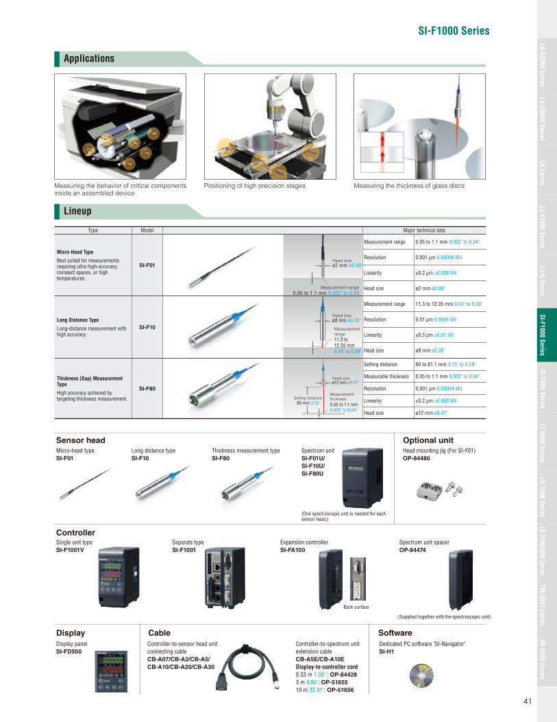
SI-F1000 Series
Head sizeø2 mm ø0.08"
Measurement range0.05 to 1.1 mm 0.002" to 0.04"
Head sizeø8 mm ø0.32"
Measurementrange11.3 to12.35 mm0.44" to 0.49"
Setting distance80 mm 3.15"
Head sizeø12 mm ø0.47"
Measurement thickness0.05 to 1.1 mm0.002" to 0.04"
Applications
Lineup
Measuring the behavior of critical components inside an assembled device
Measuring the thickness of glass discsPositioning of high precision stages
Sensor head
Controller
Micro-head typeSI-F01
Single unit typeSI-F1001V
Separate typeSI-F1001
Expansion controllerSI-FA100
Spectrum unit spacerOP-84474
Long distance typeSI-F10
Thickness measurement typeSI-F80
Spectrum unitSI-F01U/
SI-F10U/
SI-F80U
(One spectroscopic unit is needed for each sensor head.)
Back surface
(Supplied together with the spectroscopic unit)
Optional unitHead mounting jig (For SI-F01)OP-84480
Display Cable Software
Display panelSI-FD500
Controller-to-sensor head unitconnecting cableCB-A07/CB-A2/CB-A5/
CB-A10/CB-A20/CB-A30
Dedicated PC software "SI-Navigator"SI-H1
Controller-to-spectrum unit extension cableCB-A5E/CB-A10E
Display-to-controller cord0.33 m 1.08' : OP-84428
3 m 9.84': OP-51655
10 m 32.81': OP-51656
Type Model Major technical data
Micro-Head Type
Best suited for measurements requiring ultra high-accuracy, compact spaces, or high temperatures.
SI-F01
Measurement range 0.05 to 1.1 mm 0.002" to 0.04"
Resolution 0.001 μm 0.00004 Mil
Linearity ±0.2 μm ±0.008 Mil
Head size ø2 mm ø0.08"
Long Distance Type
Long-distance measurement with high accuracy.
SI-F10
Measurement range 11.3 to 12.35 mm 0.04" to 0.49"
Resolution 0.01 μm 0.0004 Mil
Linearity ±0.3 μm ±0.01 Mil
Head size ø8 mm ø0.32"
Thickness (Gap) Measurement Type
High accuracy achieved by targeting thickness measurement.
SI-F80
Setting distance 80 to 81.1 mm 3.15" to 3.19"
Measurable thickness 0.05 to 1.1 mm 0.002" to 0.04"
Resolution 0.001 μm 0.00004 Mil
Linearity ±0.2 μm ±0.008 Mil
Head size ø12 mm ø0.47"
41
LK-G5000 SeriesLK-G3000 Series
LJ-G SeriesSI-F1000 Series
SI-F80R SeriesLS-7000 Series
LS-3100/5000 SeriesTM
-3000 SeriesIM
-6500 SeriesLK Series
LJ-V7000 SeriesLT-9000 Series
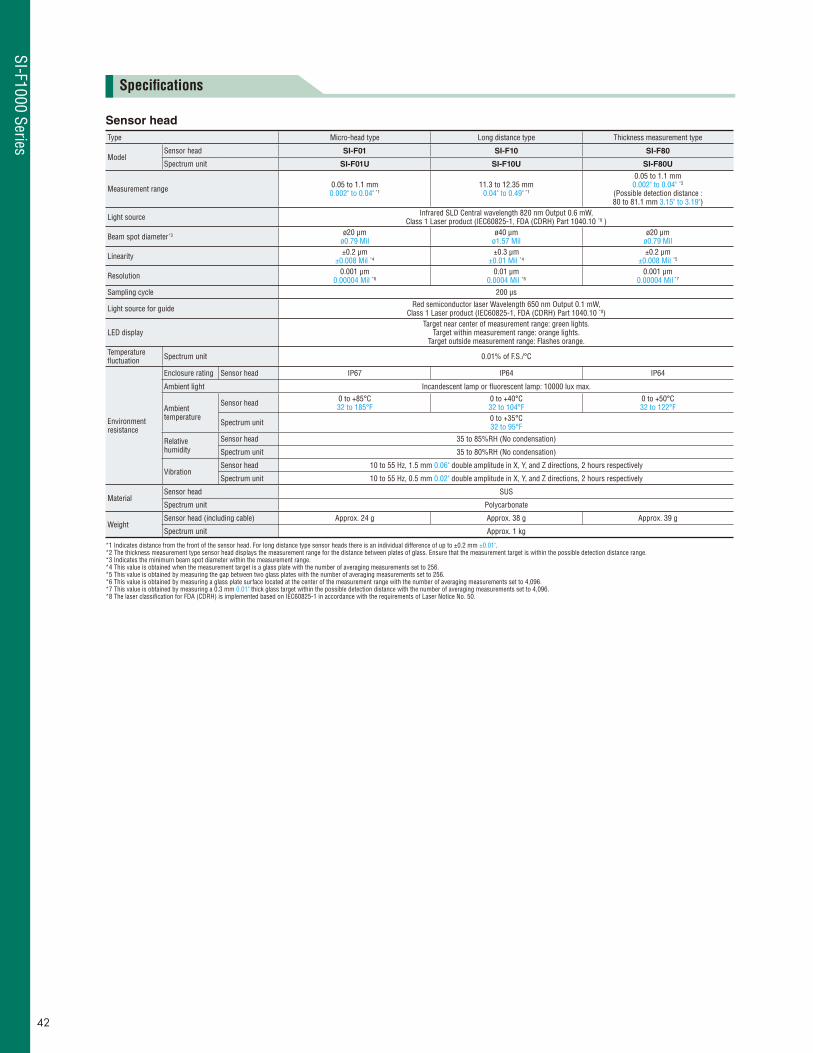
Specifi cations
Sensor head
Type Micro-head type Long distance type Thickness measurement type
ModelSensor head SI-F01 SI-F10 SI-F80
Spectrum unit SI-F01U SI-F10U SI-F80U
Measurement range 0.05 to 1.1 mm 0.002" to 0.04" *1
11.3 to 12.35 mm 0.04" to 0.49" *1
0.05 to 1.1 mm 0.002" to 0.04" *2
(Possible detection distance : 80 to 81.1 mm 3.15" to 3.19")
Light source Infrared SLD Central wavelength 820 nm Output 0.6 mW, Class 1 Laser product (IEC60825-1, FDA (CDRH) Part 1040.10 *8 )
Beam spot diameter*3 ø20 μm ø0.79 Mil
ø40 μm ø1.57 Mil
ø20 μm ø0.79 Mil
Linearity ±0.2 μm ±0.008 Mil *4
±0.3 μm ±0.01 Mil *4
±0.2 μm ±0.008 Mil *5
Resolution 0.001 μm 0.00004 Mil *6
0.01 μm 0.0004 Mil *6
0.001 μm 0.00004 Mil *7
Sampling cycle 200 μs
Light source for guide Red semiconductor laser Wavelength 650 nm Output 0.1 mW, Class 1 Laser product (IEC60825-1, FDA (CDRH) Part 1040.10 *8)
LED displayTarget near center of measurement range: green lights.
Target within measurement range: orange lights. Target outside measurement range: Flashes orange.
Temperaturefl uctuation Spectrum unit 0.01% of F.S./°C
Environmentresistance
Enclosure rating Sensor head IP67 IP64 IP64
Ambient light Incandescent lamp or fl uorescent lamp: 10000 lux max.
Ambienttemperature
Sensor head 0 to +85°C 32 to 185°F
0 to +40°C 32 to 104°F
0 to +50°C 32 to 122°F
Spectrum unit 0 to +35°C 32 to 95°F
Relativehumidity
Sensor head 35 to 85%RH (No condensation)
Spectrum unit 35 to 80%RH (No condensation)
VibrationSensor head 10 to 55 Hz, 1.5 mm 0.06" double amplitude in X, Y, and Z directions, 2 hours respectively
Spectrum unit 10 to 55 Hz, 0.5 mm 0.02" double amplitude in X, Y, and Z directions, 2 hours respectively
MaterialSensor head SUS
Spectrum unit Polycarbonate
WeightSensor head (including cable) Approx. 24 g Approx. 38 g Approx. 39 g
Spectrum unit Approx. 1 kg
*1 Indicates distance from the front of the sensor head. For long distance type sensor heads there is an individual difference of up to ±0.2 mm ±0.01".*2 The thickness measurement type sensor head displays the measurement range for the distance between plates of glass. Ensure that the measurement target is within the possible detection distance range.*3 Indicates the minimum beam spot diameter within the measurement range.*4 This value is obtained when the measurement target is a glass plate with the number of averaging measurements set to 256.*5 This value is obtained by measuring the gap between two glass plates with the number of averaging measurements set to 256.*6 This value is obtained by measuring a glass plate surface located at the center of the measurement range with the number of averaging measurements set to 4,096.*7 This value is obtained by measuring a 0.3 mm 0.01" thick glass target within the possible detection distance with the number of averaging measurements set to 4,096.*8 The laser classifi cation for FDA (CDRH) is implemented based on IEC60825-1 in accordance with the requirements of Laser Notice No. 50.
SI-F1000 Series
42

SI-F1000 Series
Controller
Type Main Controller Expansion controller*1
ModelSingle unit type SI-F1001V
SI-FA100Separate type*2 SI-F1001/SI-FD500
No. of connectable spectrum units 2 1
Display
Minimum display unit 0.001 μm 0.00004 Mil
N/ADisplay range±999.999 μm to ±9999.99 mm, ±999.999 Mil to ±9999.99 Mil
(7 settings selectable)
Display cycle 10 times/sec.
Terminalblock
Laser remote interlock input
Non-voltage input N/A
TIMING1 input
RESET1 input
Auto-zero1 input
Laser control input
Analog voltage output ±10 V x 2 outputs, Output impedance: 100 Ω
±10 V x 1 output, Output impedance: 100 Ω
Analog current output 4 to 20 mA x 2 outputs, Maximum load resistance: 350 Ω
4 to 20 mA x 1 output, Maximum load resistance: 350 Ω
Alarm output NPN open-collector output (N.C.)N/A
General comparator output NPN open-collector output
Expansionconnector
TIMING input Non-voltage input 2
N/A
RESET inputNon-voltage input
Auto-zero input
Program switch input Non-voltage input x 3 inputs
Alarm output NPN open-collector output (N.C.)
Comparator/binaryoutput
Binary output Measured value data output (21 bits) OUT selectable NPN open-collector output
Strobe output NPN open-collector output
Binary selection output NPN open-collector output
Binary selection input Non-voltage input
RS-232C interface Measured data output and control input/output (Baud rate selectable to 115,200 bps max.)
N/AUSB interface USB 2.0 high speed compliant (USB 1.1 Full-SPEED compatible)
Ethernet interface 100Base-TX/10Base-T
Major functions
12 Out simultaneous measurementcalculation, average, fi lter, scaling measurement, measured value alarm,
tolerance setting, auto-zero, data storage, light monitor, 8-program memory,interferometer mode, mask, connection of setting support software, etc.
Power supplyPower supply voltage 24 VDC±10% Ripple 10% (P-P) max.
Supplied from the main controllerMaximum current consumption One head connected: 0.6 A or less. Six heads connected: 1.5 A or less.
Environmentresistance
Ambient temperature*3 0 to +50°C 32 to 122°F
Relative humidity 35 to 85%RH (No condensation)
Vibration*4 10 to 55 Hz, 0.5 mm 0.02" double amplitude in X, Y, and Z directions, 2 hours respectively
Weight Approx. 600 g Approx. 300 g
*1 Up to four expansion controllers can be connected to the main controller.*2 The SI-F1003 can be used independently. The measured value display and setting change can be done with the display panel (SI-FD500) and setup support software (SI-H3).*3 When two or more expansion controllers are connected, the ambient temperature is 0 to 40°C 32 to 104°F.*4 When two or more expansion controllers are connected, the vibration resistance is "10 to 55 Hz, 0.3 mm 0.01" double amplitude in X, Y, and Z directions, 2 hours respectively".• NPN open-collector output rating: 50 mA max. (40 V max.), Residual voltage: 0.5 V max.• Non-voltage input rating: ON voltage: 1 V max., OFF current: 0.6 mA max.• Part of the input/output circuit of the SI Series is internally common. Be careful that no potential difference is generated between the internally common terminals due to the potential difference between the cables/external devices. For details, refer to "Precautions on wiring".
Operating environment required to use SI-H1 (SI-Navigator)
Item Minimum system requirements
CPU Pentium III, 1 GHz or higher (1.7 GHz or higher is recommended)
OS Windows 7*1/ Windows Vista*2/ Windows XP*3/Windows 2000 Professional*4
Memory capacity 256 MB or higher (1 GB or more is recommended)
Display resolution 1024 x 768 pixels, 24-bit full color or higher
Free hard disk space 1 GB or larger
Interface
One of the following interfaces is required.- USB: Revision 2.0, high-speed (full speed in USB1.1 compatible mode)*5
- LAN: 100BASE-TX or 10BASE-T*6
- RS-232C (serial port)
The other system requirements must meet those recommended for your OS.*1 Home Premium, Professional and Ultimate editions are supported.*2 Ultimate, Business, Home Premium and Home Basic editions are supported.*3 Professional SP2 and later versions and Home Edition SP2 and later versions are supported.*4 SP4 and later versions are supported.*5 Connections via a USB hub are not supported.*6 Connections via an in-house LAN or a router are not supported. Direct or local connections must be used.* Windows is a registered trademark of Microsoft Corporation.* Pentium is a registered trademark of Intel Corporation.
43
LK-G5000 SeriesLK-G3000 Series
LJ-G SeriesSI-F1000 Series
SI-F80R SeriesLS-7000 Series
LS-3100/5000 SeriesTM
-3000 SeriesIM
-6500 SeriesLK Series
LJ-V7000 SeriesLT-9000 Series

0+1000
11000
(Measurement range)
(Optical fiber)
0+1000
0.002" to 0.04"
0.05 to 1.1
ø2
ø1.25±0.01 ø0.05" ±0.0004"
1
0.04"
110.43"
(10) 0.39"
11000
0+39.37"
433.07"
0+100011000
0+39.37"
433.07"
0+39.37"
433.07"
250.98"
250.98"
0.33"
9 0.35"
9 0.35"
8.3 0.33"
90.35"
8.3
ø0.9 ø0.04"(Optical fiber)
ø0.9 ø0.04"
-0.0080 ø0.08 -0.0003"
0
(Optical fiber)
0.05 to 1.1
(Measurement range)
0 to 1.1
(Detection range)
-0.01-0.05
-0.01-0.05ø12-0.0004"
-0.002"ø0.47" ø8 -0.0004" -0.002"
ø0.32"
8.3 0.33"
250.98"
(19)282180(0.75")1.1"0.83"3.15"
ø0.9 ø0.04"
0" to 0.04"
0.002" to 0.04"
(Measurement range)
-0.05-0.01ø8 -0.002"
-0.0004"ø0.32"
(19.2)(0.76")
42.31.67"
11.3 to 12.350.44" to 0.49"
SUS304
M2 Set screw
7
C1
2 x ø2.5Spot facing: ø5 ø0.2, Depth: 2.5 0.1"
10.5 0.41"
3.50.14"
0.12"
0.28"
60.24"
0.24"
0.47"
3.1 max.
12
3 0.12"
30.12"
6
ø0.1
Depth: 6
4xM413.50.53"
79.59
47
35.9
62.1
1.41"
2.24"
DIN rail
(63)127.5(2.56")
(63)(2.56")5.04"
65
6
124
9
47
79.534.53.13"1.36"
4xM4
Depth: 6 3.13"
0.35"
0.24"
1.85"
0.35"
1.85"
0.24"
2.56"65
2.56"
4.88"
1244.88"
0.24" 6 0.24"
1054.13"
(With decorative panel) (Without decorative panel)
Sensor head
Micro-head typeSI-F01
Spectrum unit
SI-F01U/SI-F10U/SI-F80U
Thickness measurement typeSI-F80
Head mounting jig (For SI-F01)OP-84480
Long distance typeSI-F10
DimensionsUnit: mm inch
SI-F1000 Series
44

SI-F1000 Series
6
124
Panel cutout
65 128
9
47
4xM4
Depth: 679.5
6
34.5
(65)
124
(2.56")2.56" 5.04"
4.88"
0.24"
1.85"
0.35"0.24"1.36" 3.13"
0.55"
(2.56")2.56" 4.15"
4.88"
DIN rail
65 105.5
47 1.85"
3.13"
0.35"
Depth: 6
4xM4
6
14 79.5
124
(65)
62.1
35.9
9
0.24"
0.24"
1.41"
2.44"
26.31.04"
128
13.5 0.53"
Depth: 6
M4
6 0.24"
114 4.49"
(65)5.04" (2.56")
1244.88"
0.24"
4.88"
0.24"
(With decorative panel) (Without decorative panel)
DIN rail
26.3 105.5
62.1
M4
Depth: 6
13.5 14
(65)
35.9
1.04"
0.53"0.55"
(2.56") 4.15"
0.24"
1.41"
2.44"
+0.60
62min.
0+0.6
45
0+0.02"1.77"
75+0.02"
02.95"
100min.
130.51"
0.5 to 5 mm0.02" to 0.2"
Panel thickness:
1.81"
2.44"
46
62
8.5
25
74.52.93"
0.98"
0.33"
80
91
3.15"
3.58"
Display panelattachment ring
2.44"
3.94"
ø7 ø0.28"Cable length (0.7 m, 2 m, 5 m, 10 m, 20 m, 30 m)(2.30', 6.56', 16.40', 32.81', 65.62', 98.42')
11.5
26
3355
ø141.30"
1.02"
2.17"
0.45"
ø0.55"
ø7 ø0.28"Cable length (5 m, 10 m) (16.40', 32.81')
55
ø14
55
ø14ø0.55"
ø0.55"2.17"
2.17"
Controller
Single unit typeSI-F1001V
Display
Display panelSI-FD500
Additional accessories
Controller-to-spectroscopic unit connection cableCB-A07/CB-A2/CB-A5/CB-A10/CB-A20/CB-A30
Expansion controllerSI-FA100
Separate typeSI-F1001
45
LK-G5000 SeriesLK-G3000 Series
LJ-G SeriesSI-F1000 Series
SI-F80R SeriesLS-7000 Series
LS-3100/5000 SeriesTM
-3000 SeriesIM
-6500 SeriesLK Series
LJ-V7000 SeriesLT-9000 Series
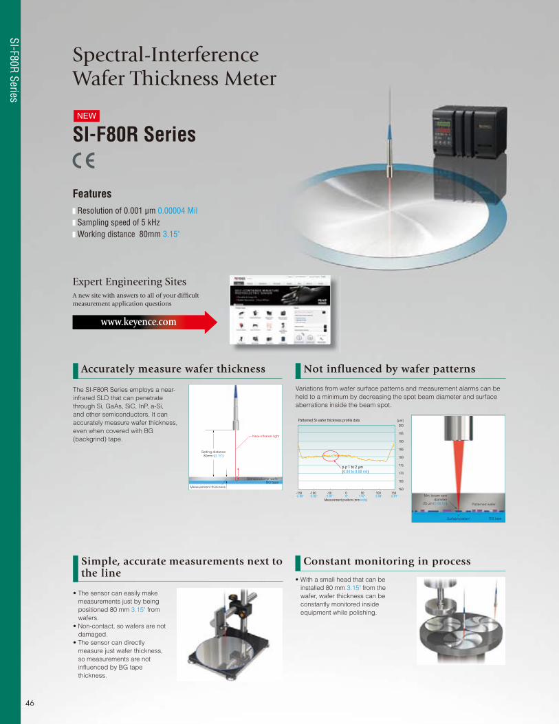
Spectral-Interference Wafer Thickness Meter
SI-F80R Series
Features Resolution of 0.001 μm 0.00004 Mil Sampling speed of 5 kHz Working distance 80mm 3.15"
Expert Engineering SitesA new site with answers to all of your diffi cult measurement application questions
www.keyence.com
Accurately measure wafer thickness Not influenced by wafer patterns
Simple, accurate measurements next to the line
Constant monitoring in process
Variations from wafer surface patterns and measurement alarms can be
held to a minimum by decreasing the spot beam diameter and surface
aberrations inside the beam spot.
• The sensor can easily make
measurements just by being
positioned 80 mm 3.15" from
wafers.
• Non-contact, so wafers are not
damaged.
• The sensor can directly
measure just wafer thickness,
so measurements are not
infl uenced by BG tape
thickness.
• With a small head that can be
installed 80 mm 3.15" from the
wafer, wafer thickness can be
constantly monitored inside
equipment while polishing.
The SI-F80R Series employs a near-
infrared SLD that can penetrate
through Si, GaAs, SiC, InP, a-Si,
and other semiconductors. It can
accurately measure wafer thickness,
even when covered with BG
(backgrind) tape.
NEW
Near-infrared light
Setting distance80mm (3.15")
Measurement thickness
Semiconductor waferBG tape
BG tape
Min. beam spotdiameter
25 μm (0.98 Mil) Patterned wafer
Surface pattern
Patterned Si wafer thickness profile data
160
165
170
175
180
185
190
195
200
[μm]
-150 -100 -50 0 50 100 150-5.90" -3.93" -1.97" 0" 1.97" 3.94" 5.91"
Measurement position (mm inch)
p-p 1 to 2 μm (0.04 to 0.08 mil)
SI-F80R Series
46

SI-F80R Series
Lineup
Components External deviceSensor headWafer thicknessmeasurement typeSI-F80R
IR sensor cardSpectrum unitSI-F80RU
Specifi cations
Dimensions
Type Wafer thickness measurement type
ModelSensor head SI-F80R
Spectrum unit SI-F80RU
Measurement range *1 10 to 310 μm 0.39 Mil to 12.2 Mil (when n=3.5)Possible detection distance 80 to 81.1 mm 3.15" to 3.19"Light source Infrared SLD Output 0.6 mW, Class 1 Laser Product (IEC60825-1, FDA (CDRH) Part 1040.10 *5 )Beam spot diameter *2 ø25 μm ø0.98 MilLinearity *3 ±0.1 μm ±0.004 Mil (when n=3.5)Resolution *4 1 nm 0.00004 MilSampling cycle 200 μs
LED display Target near center of measurement range: green lights. Target within measurement range: orange lights. Target outside measurement range: fl ashes orange.
Temperature fl uctuation Spectrum unit 0.01% of F.S./°C
Environment resistance
Enclosure rating Sensor head IP64Ambient light Incandescent lamp or fl uorescent lamp: 10000 lux max.
Ambient temperatureSensor head 0 to +50°C 32 to 122°FSpectrum unit 0 to +35°C 32 to 95°F
Relative humiditySensor head 35 to 85% RH (No condensation)Spectrum unit 35 to 85% RH (No condensation)
Vibration Sensor head 10 to 55 Hz, 1.5 mm 0.06" double amplitude in X, Y, and Z directions, 2 hours respectivelySpectrum unit 10 to 55 Hz, 0.5 mm 0.02" double amplitude in X, Y, and Z directions, 2 hours respectively
MaterialSensor head SUSSpectrum unit Polycarbonate
WeightSensor head (including cable) Approx. 70 gSpectrum unit Approx. 1.2 kg
The sensor head and spectrum unit are calibrated as a pair. They are not interchangeable. *1 Indicates the thickness measurement range when the refractive index is 3.5. (The thickness measurement range is 35 to 1100 μm 1.38 to 43.31 Mil when the refractive index is 1.)*2 Indicates the minimum beam spot diameter within the measurement range.*3 This value is obtained by measuring the gap between two glass plates with the number of averaging measurements set to 256, converted to a refractive index of 3.5.*4 This value is obtained by measuring a 0.3 mm 0.01" thick glass target within the possible detection distance with the number of averaging measurements set to 4096.*5 The laser classifi cation for FDA (CDRH) is implemented based on IEC60825-1 in accordance with the requirements of Laser Notice No. 50.
Depth: 65xM4
(63)
DIN rail mount
Depth: 65xM4
(63)
13.5
-0.01-0.05-0.0004"-0.002"
-0.01-0.05-0.0004"-0.002"
(26)
ø2.0
+1000
+39.37"0
0
(Optical fiber)
0 to 1.1 0.04"Detection range
0.05 to 1.10.002" to 0.04" Measurement range
803.15"
3.59" 3.59"
4.88"
0.24"
5.02" 2.48" 2.48" 4.13"
0.83" 1.10" 0.71" 1.02" 433.07" 21 28 18 11000
25
8.3
9
ø7.5±0.1ø0.30"±0.004"
ø8ø12
35.9
62.1
10591.3127.591.3
6
9
124
34.5 79.5
47
22.5
22.5
47
9
79.5
0.98"
0.33"
0.35"
1.41"
2.44"
ø0.08"
ø0.47" ø0.31"
4.88" 124
0.24" 6
0.24" 0.24"
0.35"
1.85"
0.89"
1.36" 3.13"
0.89"
1.85"
0.35"
3.13" 0.53"
SI-F80R
SI-F80RU
Unit: mm inch
47
LK-G5000 SeriesLK-G3000 Series
LJ-G SeriesSI-F1000 Series
SI-F80R SeriesLS-7000 Series
LS-3100/5000 SeriesTM
-3000 SeriesIM
-6500 SeriesLK Series
LJ-V7000 SeriesLT-9000 Series
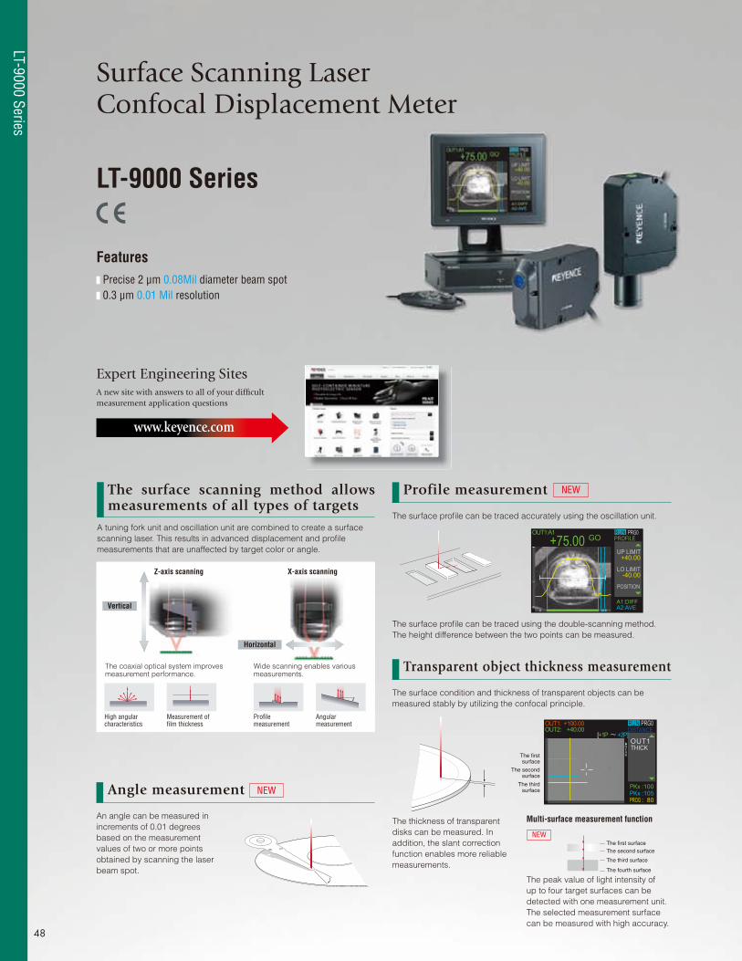
Expert Engineering Sites
Surface Scanning Laser Confocal Displacement Meter
LT-9000 Series
Features Precise 2 μm 0.08Mil diameter beam spot 0.3 μm 0.01 Mil resolution
A new site with answers to all of your diffi cult measurement application questions
www.keyence.com
Angle measurement
Transparent object thickness measurement
An angle can be measured in
increments of 0.01 degrees
based on the measurement
values of two or more points
obtained by scanning the laser
beam spot.
The surface condition and thickness of transparent objects can be
measured stably by utilizing the confocal principle.
NEW
A tuning fork unit and oscillation unit are combined to create a surface
scanning laser. This results in advanced displacement and profi le
measurements that are unaffected by target color or angle.
The surface profi le can be traced accurately using the oscillation unit.
The surface profi le can be traced using the double-scanning method.
The height difference between the two points can be measured.
The surface scanning method allows measurements of all types of targets
Profile measurement
Vertical
Z-axis scanning X-axis scanning
Horizontal
The coaxial optical system improves measurement performance.
High angular characteristics
Measurement of fi lm thickness
Wide scanning enables various measurements.
Profi le measurement
Angular measurement
NEW
OUT1:A1 PRG0GO
RUNPROFILE+75.00
+40.00
A1:DIFFA2:AVE
UP LIMIT
-40.00LO LIMIT
POSITION
OUT1:OUT2:
+100.00+40.00
[+1P +2P]
PRG0RUNDISTANCE
THICKNEAR
PKxPKxPROG
:100:105: 80
OUT1
The firstsurface
The secondsurface
The thirdsurface
The first surfaceThe second surface
The third surface
The fourth surface
The thickness of transparent
disks can be measured. In
addition, the slant correction
function enables more reliable
measurements.
The peak value of light intensity of
up to four target surfaces can be
detected with one measurement unit.
The selected measurement surface
can be measured with high accuracy.
Multi-surface measurement function
NEW
48
LT-9000 Series
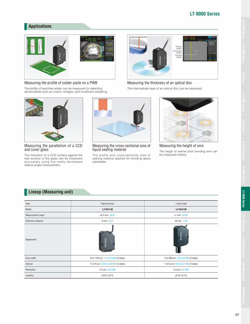
LT-9000 Series
Applications
Lineup (Measuring unit)
OUT1:A1 PRG0GO
RUNPROFILE+75.00
+40.00
A1:DIFFA2:AVE
UP LIMIT
-40.00LO LIMIT
POSITION
OUT1:OUT2:
+100.00+40.00
[+1P +2P]
PRG0RUNDISTANCE
THICKNEAR
PKxPKxPROG
:100:105: 80
OUT1
The firstsurface
The secondsurface
The thirdsurface
Measuring the profi le of solder paste on a PWBThe profi le of lead-free solder can be measured for detecting abnormalities such as cracks, bridges, and insuffi cient soldering.
Measuring the thickness of an optical discThe intermediate layer of an optical disc can be measured.
Type High-accuracy Long-range
Model LT-9011M LT-9031M
Measurement range ±0.3 mm ±0.01" ±1 mm ±0.04"
Reference distance 6 mm 0.24" 30 mm 1.18"
Appearance
Scan width 0 to 1100 μm 0 to 43.3 Mil (6 steps) 0 to 560 μm 0 to 22.0 Mil (6 steps)
Interval 1 to 10 μm 0.04 to 0.39 Mil (4 steps) 1 to 8 μm 0.04 to 0.31 Mil (4 steps)
Resolution 0.3 μm 0.01 Mil 0.3 μm 0.01 Mil
Linearity ±0.5% of F.S. ±0.3% of F.S.
Measuring the parallelism of a CCD and cover glassThe inclination of a CCD surface against the rear surface of the glass can be measured accurately using the newly developed relative angle measurement.
Measuring the height of wireThe height of narrow pitch bonding wire can be measured reliably.
Measuring the cross-sectional area of liquid sealing materialThe profile and cross-sectional area of sealing material applied for bonding glass substrates.
49
LK-G5000 SeriesLK-G3000 Series
LJ-G SeriesSI-F1000 Series
SI-F80R SeriesLS-7000 Series
LS-3100/5000 SeriesTM
-3000 SeriesIM
-6500 SeriesLK Series
LJ-V7000 SeriesLT-9000 Series
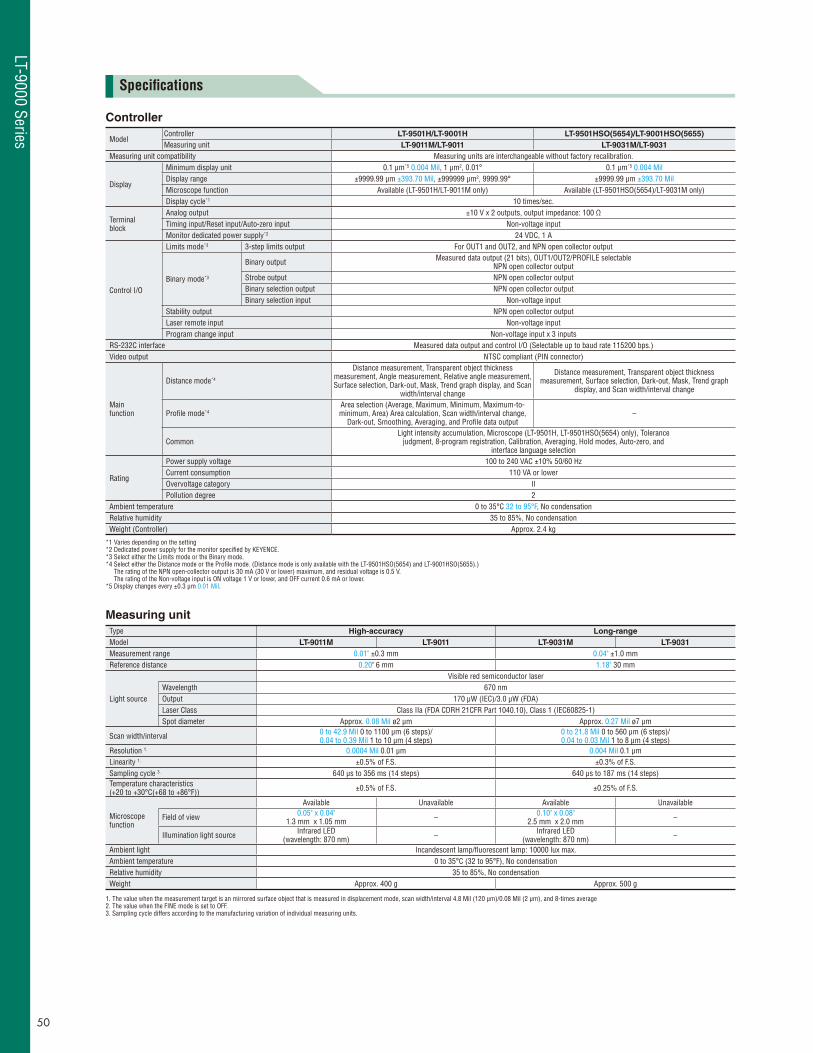
Specifi cations
Controller
ModelController LT-9501H/LT-9001H LT-9501HSO(5654)/LT-9001HSO(5655)
Measuring unit LT-9011M/LT-9011 LT-9031M/LT-9031
Measuring unit compatibility Measuring units are interchangeable without factory recalibration.
Display
Minimum display unit 0.1 μm*5 0.004 Mil, 1 μm2, 0.01° 0.1 μm*5 0.004 MilDisplay range ±9999.99 μm ±393.70 Mil, ±999999 μm2, 9999.99° ±9999.99 μm ±393.70 MilMicroscope function Available (LT-9501H/LT-9011M only) Available (LT-9501HSO(5654)/LT-9031M only)Display cycle*1 10 times/sec.
Terminalblock
Analog output ±10 V x 2 outputs, output impedance: 100 ΩTiming input/Reset input/Auto-zero input Non-voltage inputMonitor dedicated power supply*2 24 VDC, 1 A
Control I/O
Limits mode*3 3-step limits output For OUT1 and OUT2, and NPN open collector output
Binary mode*3
Binary output Measured data output (21 bits), OUT1/OUT2/PROFILE selectable NPN open collector output
Strobe output NPN open collector outputBinary selection output NPN open collector outputBinary selection input Non-voltage input
Stability output NPN open collector outputLaser remote input Non-voltage inputProgram change input Non-voltage input x 3 inputs
RS-232C interface Measured data output and control I/O (Selectable up to baud rate 115200 bps.)Video output NTSC compliant (PIN connector)
Mainfunction
Distance mode*4
Distance measurement, Transparent object thickness measurement, Angle measurement, Relative angle measurement, Surface selection, Dark-out, Mask, Trend graph display, and Scan
width/interval change
Distance measurement, Transparent object thickness measurement, Surface selection, Dark-out, Mask, Trend graph
display, and Scan width/interval change
Profi le mode*4Area selection (Average, Maximum, Minimum, Maximum-to-minimum, Area) Area calculation, Scan width/interval change,
Dark-out, Smoothing, Averaging, and Profi le data output–
CommonLight intensity accumulation, Microscope (LT-9501H, LT-9501HSO(5654) only), Tolerance
judgment, 8-program registration, Calibration, Averaging, Hold modes, Auto-zero, andinterface language selection
Rating
Power supply voltage 100 to 240 VAC ±10% 50/60 HzCurrent consumption 110 VA or lowerOvervoltage category IIPollution degree 2
Ambient temperature 0 to 35°C 32 to 95°F, No condensationRelative humidity 35 to 85%, No condensationWeight (Controller) Approx. 2.4 kg
*1 Varies depending on the setting*2 Dedicated power supply for the monitor specifi ed by KEYENCE.*3 Select either the Limits mode or the Binary mode.*4 Select either the Distance mode or the Profi le mode. (Distance mode is only available with the LT-9501HSO(5654) and LT-9001HSO(5655).)
The rating of the NPN open-collector output is 30 mA (30 V or lower) maximum, and residual voltage is 0.5 V. The rating of the Non-voltage input is ON voltage 1 V or lower, and OFF current 0.6 mA or lower.
*5 Display changes every ±0.3 μm 0.01 Mil.
Measuring unit
Type High-accuracy Long-range
Model LT-9011M LT-9011 LT-9031M LT-9031
Measurement range 0.01" ±0.3 mm 0.04" ±1.0 mmReference distance 0.20" 6 mm 1.18" 30 mm
Light source
Visible red semiconductor laserWavelength 670 nmOutput 170 μW (IEC)/3.0 μW (FDA)Laser Class Class IIa (FDA CDRH 21CFR Part 1040.10), Class 1 (IEC60825-1)Spot diameter Approx. 0.08 Mil ø2 μm Approx. 0.27 Mil ø7 μm
Scan width/interval 0 to 42.9 Mil 0 to 1100 μm (6 steps)/0.04 to 0.39 Mil 1 to 10 μm (4 steps)
0 to 21.8 Mil 0 to 560 μm (6 steps)/0.04 to 0.03 Mil 1 to 8 μm (4 steps)
Resolution 1. 0.0004 Mil 0.01 μm 0.004 Mil 0.1 μmLinearity 1. ±0.5% of F.S. ±0.3% of F.S.Sampling cycle 3. 640 μs to 356 ms (14 steps) 640 μs to 187 ms (14 steps)Temperature characteristics (+20 to +30°C(+68 to +86°F)) ±0.5% of F.S. ±0.25% of F.S.
Microscope function
Available Unavailable Available Unavailable
Field of view 0.05" x 0.04" 1.3 mm x 1.05 mm – 0.10" x 0.08"
2.5 mm x 2.0 mm –
Illumination light source Infrared LED (wavelength: 870 nm) – Infrared LED
(wavelength: 870 nm) –
Ambient light Incandescent lamp/fl uorescent lamp: 10000 lux max.Ambient temperature 0 to 35°C (32 to 95°F), No condensationRelative humidity 35 to 85%, No condensationWeight Approx. 400 g Approx. 500 g
1. The value when the measurement target is an mirrored surface object that is measured in displacement mode, scan width/interval 4.8 Mil (120 μm)/0.08 Mil (2 μm), and 8-times average2. The value when the FINE mode is set to OFF. 3. Sampling cycle differs according to the manufacturing variation of individual measuring units.
50
LT-9000 Series
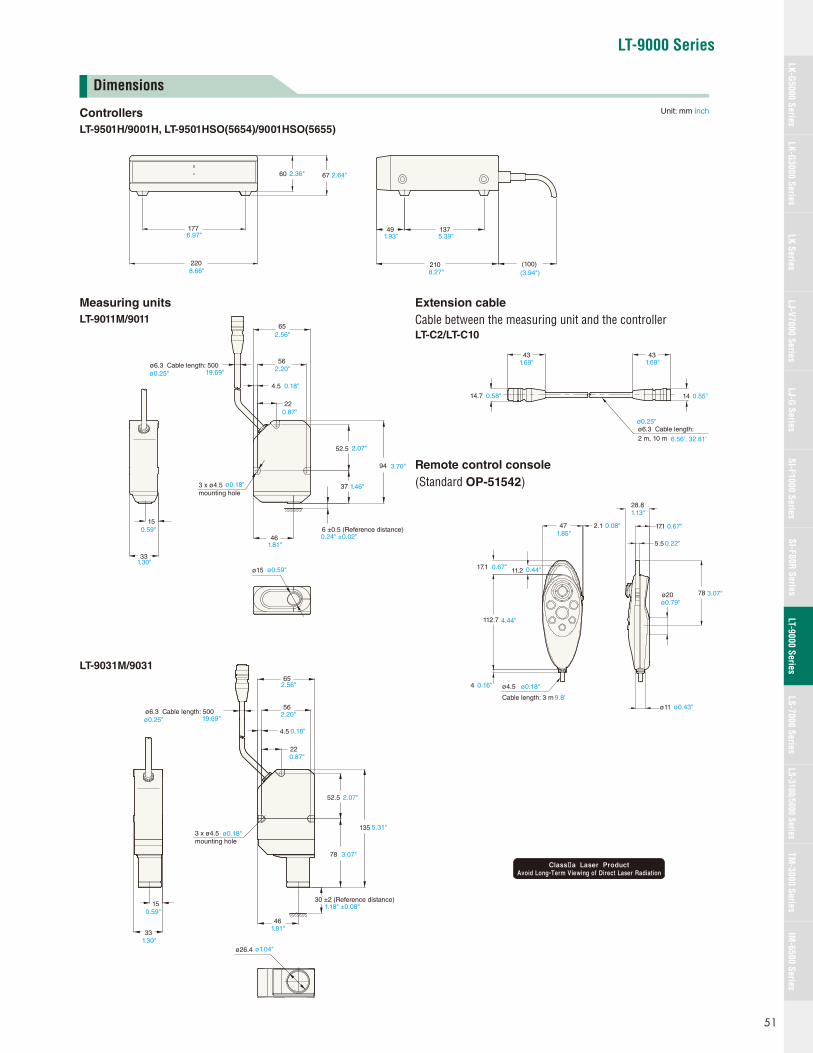
LT-9000 Series
6760
220
1776.97"
8.66"210
13749
(100)
2.36" 2.64"
1.93" 5.39"
8.27" (3.94")
56
65
52.5
94
37
6 ±0.5 (Reference distance)46
33
15
ø6.3 Cable length: 500
3 x ø4.5mounting hole
ø15
ø0.25" 19.69"
2.56"
2.20"
0.59"
1.30"
1.81"
ø0.59"
ø0.18"
2.07"
3.70"
1.46"
0.24" ±0.02"
220.87"
4.5 0.18"
ø6.3 Cable length: 2 m, 10 m
43 43
14.7 14
ø0.25"
6.56', 32.81'
1.69"1.69"
0.55"0.58"
Cable length: 3 m
ø4.5
11.2
47 2.1
17.1
4
112.7
17.1
5.5
ø11
78
28.8
ø20
1.85"0.08"
1.13"
0.67"
4.44"
0.44"
0.16" ø0.18"
9.8'
0.67"
0.22"
ø0.79"3.07"
ø0.43"
22
4.5
56
65
33
15
ø6.3 Cable length: 500
135
ø26.4
30 ±2 (Reference distance)
0.59"
1.30"
3 x ø4.5mounting hole
19.69"
2.56"
2.20"
0.18"
0.87"
5.31"
ø1.04"
ø0.18"
1.18" ±0.08"
ø0.25"
78 3.07"
52.5 2.07"
461.81"
Dimensions
Controllers
LT-9501H/9001H, LT-9501HSO(5654)/9001HSO(5655)
Unit: mm inch
Remote control console
(Standard OP-51542)
Extension cable
Cable between the measuring unit and the controller LT-C2/LT-C10
Measuring units
LT-9011M/9011
LT-9031M/9031
51
LK-G5000 SeriesLK-G3000 Series
LJ-G SeriesSI-F1000 Series
SI-F80R SeriesLS-7000 Series
LS-3100/5000 SeriesTM
-3000 SeriesIM
-6500 SeriesLK Series
LJ-V7000 SeriesLT-9000 Series
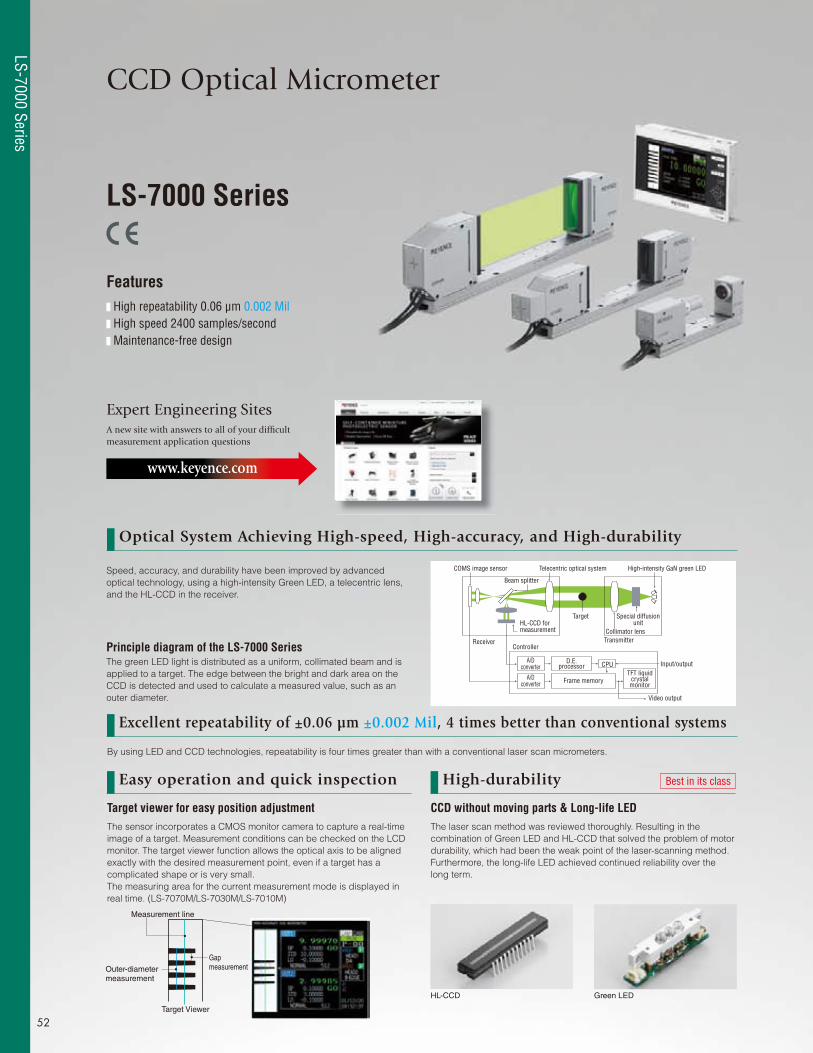
CCD Optical Micrometer
LS-7000 Series
Features High repeatability 0.06 μm 0.002 Mil High speed 2400 samples/second Maintenance-free design
Expert Engineering SitesA new site with answers to all of your diffi cult measurement application questions
www.keyence.com
Optical System Achieving High-speed, High-accuracy, and High-durability
COMS image sensor Telecentric optical system High-intensity GaN green LED
Beam splitter
Target Special diffusion unit
Collimator lensTransmitterReceiver
Controller
A/D converter
A/D converter Frame memory
D.E. processor CPU
TFT liquid crystal monitor
Video output
Input/output
HL-CCD for measurement
Measurement line
Outer-diameter measurement
Gap measurement
Target Viewer
Target viewer for easy position adjustmentThe sensor incorporates a CMOS monitor camera to capture a real-time
image of a target. Measurement conditions can be checked on the LCD
monitor. The target viewer function allows the optical axis to be aligned
exactly with the desired measurement point, even if a target has a
complicated shape or is very small.
The measuring area for the current measurement mode is displayed in
real time. (LS-7070M/LS-7030M/LS-7010M)
CCD without moving parts & Long-life LEDThe laser scan method was reviewed thoroughly. Resulting in the
combination of Green LED and HL-CCD that solved the problem of motor
durability, which had been the weak point of the laser-scanning method.
Furthermore, the long-life LED achieved continued reliability over the
long term.
Easy operation and quick inspection High-durability Best in its class
HL-CCD Green LED
Speed, accuracy, and durability have been improved by advanced
optical technology, using a high-intensity Green LED, a telecentric lens,
and the HL-CCD in the receiver.
Principle diagram of the LS-7000 SeriesThe green LED light is distributed as a uniform, collimated beam and is
applied to a target. The edge between the bright and dark area on the
CCD is detected and used to calculate a measured value, such as an
outer diameter.
By using LED and CCD technologies, repeatability is four times greater than with a conventional laser scan micrometers.
Excellent repeatability of ±0.06 μm ±0.002 Mil, 4 times better than conventional systems
52
LS-7000 Series
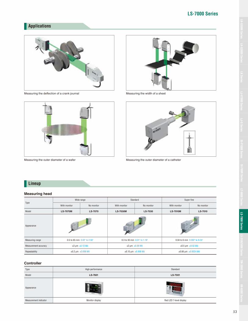
LS-7000 Series
Lineup
Measuring the width of a sheet
Measuring the outer diameter of a wafer
Measuring the defl ection of a crank journal
Measuring the outer diameter of a catheter
Applications
Measuring head
TypeWide range Standard Super fi ne
With monitor No monitor With monitor No monitor With monitor No monitor
Model LS-7070M LS-7070 LS-7030M LS-7030 LS-7010M LS-7010
Appearance
Measuring range 0.5 to 65 mm 0.02" to 2.56" 0.3 to 30 mm 0.01" to 1.18" 0.04 to 6 mm 0.002" to 0.24"
Measurement accuracy ±3 μm ±0.12 Mil ±2 μm ±0.08 Mil ±0.5 μm ±0.02 Mil
Repeatability ±0.2 μm ±0.008 Mil ±0.15 μm ±0.006 Mil ±0.06 μm ±0.0024 Mil
Controller
Type High-performance Standard
Model LS-7601 LS-7001
Appearance
Measurement indicator Monitor display Red LED 7-level display
53
LK-G5000 SeriesLK-G3000 Series
LJ-G SeriesSI-F1000 Series
SI-F80R SeriesLS-7000 Series
LS-3100/5000 SeriesTM
-3000 SeriesIM
-6500 SeriesLK Series
LJ-V7000 SeriesLT-9000 Series
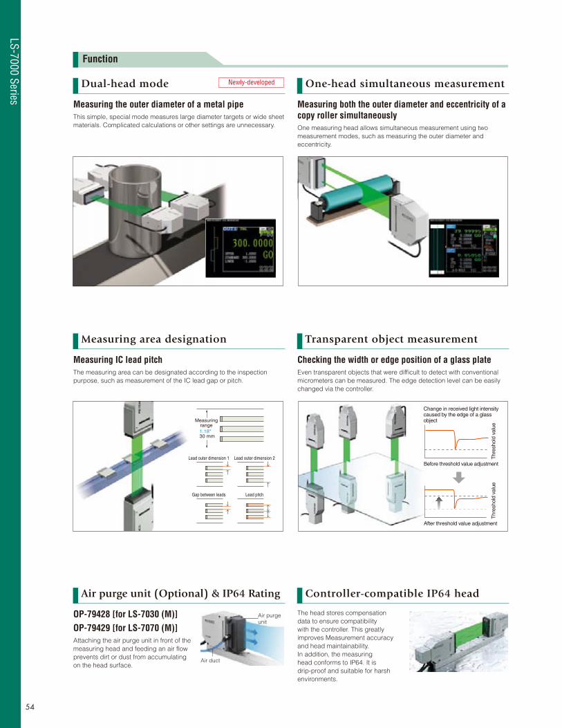
Measuringrange1.18"30 mm
Lead outer dimension 1 Lead outer dimension 2
Gap between leads Lead pitch
After threshold value adjustment
Before threshold value adjustment
Change in received light intensity caused by the edge of a glass object
Thr
esho
ld v
alue
Thr
esho
ld v
alue
Air purge unit
Air duct
Function
Dual-head mode
Measuring area designation
Air purge unit (Optional) & IP64 Rating
Transparent object measurement
Controller-compatible IP64 head
One-head simultaneous measurement
Measuring the outer diameter of a metal pipeThis simple, special mode measures large diameter targets or wide sheet
materials. Complicated calculations or other settings are unnecessary.
Measuring IC lead pitchThe measuring area can be designated according to the inspection
purpose, such as measurement of the IC lead gap or pitch.
OP-79428 [for LS-7030 (M)]OP-79429 [for LS-7070 (M)]Attaching the air purge unit in front of the
measuring head and feeding an air fl ow
prevents dirt or dust from accumulating
on the head surface.
Checking the width or edge position of a glass plateEven transparent objects that were diffi cult to detect with conventional
micrometers can be measured. The edge detection level can be easily
changed via the controller.
The head stores compensation
data to ensure compatibility
with the controller. This greatly
improves Measurement accuracy
and head maintainability.
In addition, the measuring
head conforms to IP64. It is
drip-proof and suitable for harsh
environments.
Measuring both the outer diameter and eccentricity of a copy roller simultaneouslyOne measuring head allows simultaneous measurement using two
measurement modes, such as measuring the outer diameter and
eccentricity.
Newly-developed
54
LS-7000 Series
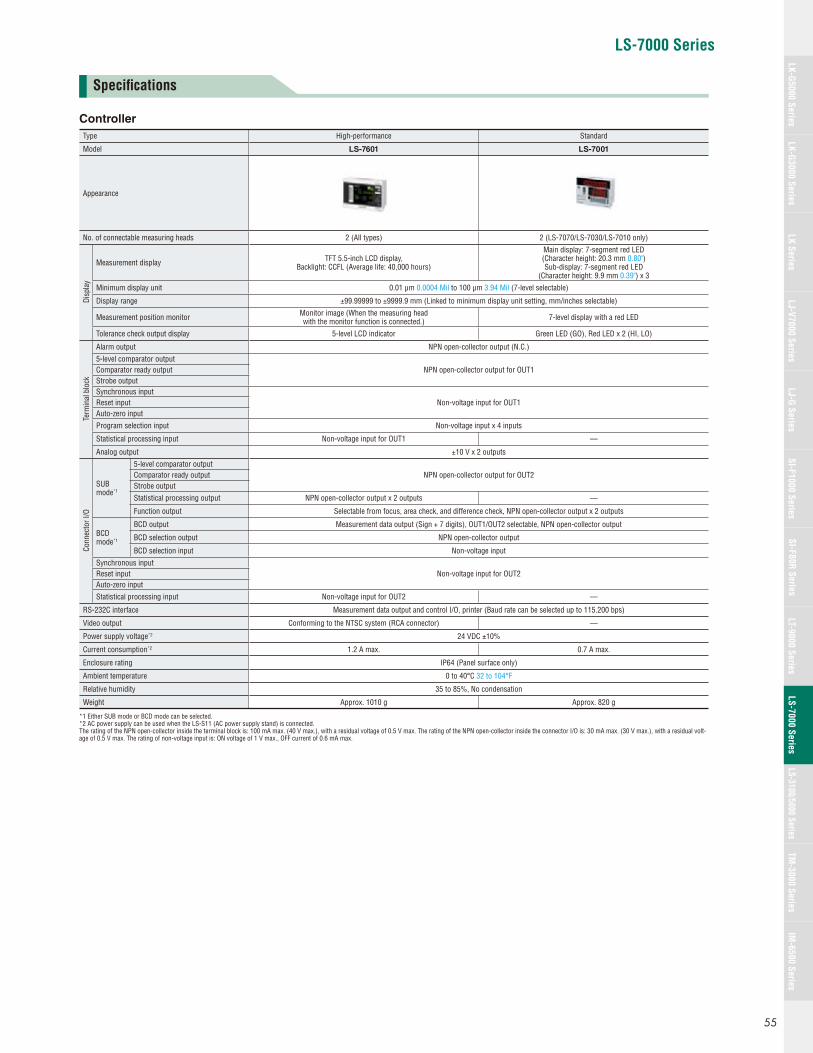
LS-7000 Series
Specifi cations
Controller
Type High-performance Standard
Model LS-7601 LS-7001
Appearance
No. of connectable measuring heads 2 (All types) 2 (LS-7070/LS-7030/LS-7010 only)
Disp
lay
Measurement display TFT 5.5-inch LCD display, Backlight: CCFL (Average life: 40,000 hours)
Main display: 7-segment red LED(Character height: 20.3 mm 0.80")Sub-display: 7-segment red LED
(Character height: 9.9 mm 0.39") x 3
Minimum display unit 0.01 μm 0.0004 Mil to 100 μm 3.94 Mil (7-level selectable)
Display range ±99.99999 to ±9999.9 mm (Linked to minimum display unit setting, mm/inches selectable)
Measurement position monitor Monitor image (When the measuring head with the monitor function is connected.) 7-level display with a red LED
Tolerance check output display 5-level LCD indicator Green LED (GO), Red LED x 2 (HI, LO)
Term
inal
blo
ck
Alarm output NPN open-collector output (N.C.)
5-level comparator outputNPN open-collector output for OUT1Comparator ready output
Strobe outputSynchronous input
Non-voltage input for OUT1Reset inputAuto-zero input
Program selection input Non-voltage input x 4 inputs
Statistical processing input Non-voltage input for OUT1 —
Analog output ±10 V x 2 outputs
Conn
ecto
r I/O
SUBmode*1
5-level comparator outputNPN open-collector output for OUT2Comparator ready output
Strobe output
Statistical processing output NPN open-collector output x 2 outputs —
Function output Selectable from focus, area check, and difference check, NPN open-collector output x 2 outputs
BCDmode*1
BCD output Measurement data output (Sign + 7 digits), OUT1/OUT2 selectable, NPN open-collector output
BCD selection output NPN open-collector output
BCD selection input Non-voltage input
Synchronous inputNon-voltage input for OUT2Reset input
Auto-zero input
Statistical processing input Non-voltage input for OUT2 —
RS-232C interface Measurement data output and control I/O, printer (Baud rate can be selected up to 115.200 bps)
Video output Conforming to the NTSC system (RCA connector) —
Power supply voltage*2 24 VDC ±10%
Current consumption*2 1.2 A max. 0.7 A max.
Enclosure rating IP64 (Panel surface only)
Ambient temperature 0 to 40°C 32 to 104°F
Relative humidity 35 to 85%, No condensation
Weight Approx. 1010 g Approx. 820 g
*1 Either SUB mode or BCD mode can be selected.*2 AC power supply can be used when the LS-S11 (AC power supply stand) is connected.The rating of the NPN open-collector inside the terminal block is: 100 mA max. (40 V max.), with a residual voltage of 0.5 V max. The rating of the NPN open-collector inside the connector I/O is: 30 mA max. (30 V max.), with a residual volt-age of 0.5 V max. The rating of non-voltage input is: ON voltage of 1 V max., OFF current of 0.6 mA max.
55
LK-G5000 SeriesLK-G3000 Series
LJ-G SeriesSI-F1000 Series
SI-F80R SeriesLS-7000 Series
LS-3100/5000 SeriesTM
-3000 SeriesIM
-6500 SeriesLK Series
LJ-V7000 SeriesLT-9000 Series
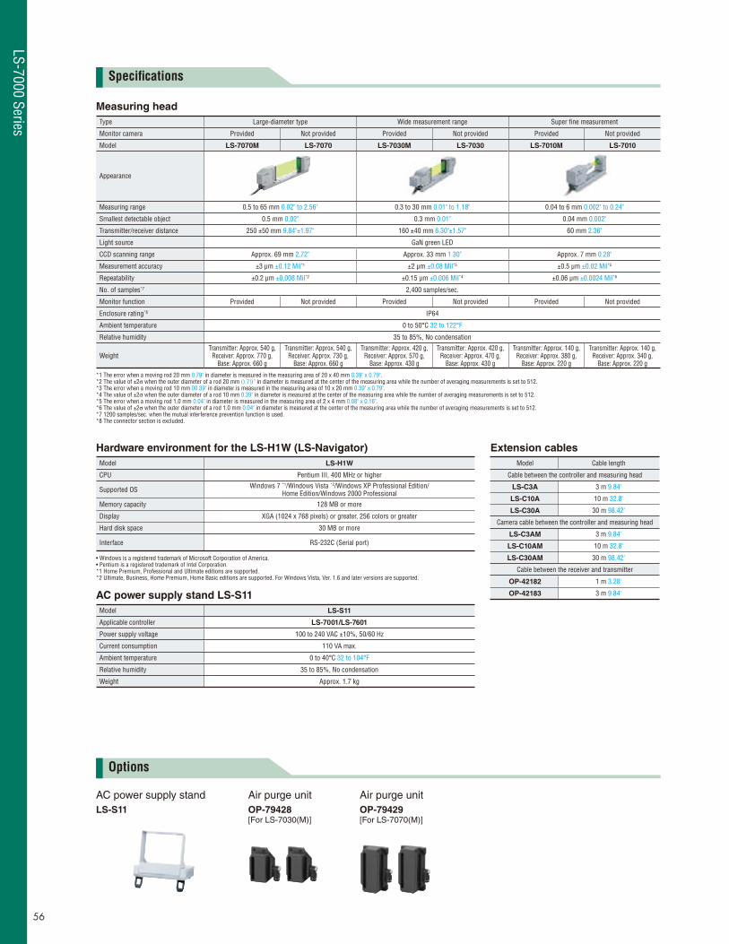
Air purge unitOP-79428[For LS-7030(M)]
Air purge unitOP-79429[For LS-7070(M)]
AC power supply standLS-S11
Specifi cations
Options
Measuring head
Type Large-diameter type Wide measurement range Super fi ne measurement
Monitor camera Provided Not provided Provided Not provided Provided Not provided
Model LS-7070M LS-7070 LS-7030M LS-7030 LS-7010M LS-7010
Appearance
Measuring range 0.5 to 65 mm 0.02" to 2.56" 0.3 to 30 mm 0.01" to 1.18" 0.04 to 6 mm 0.002" to 0.24"
Smallest detectable object 0.5 mm 0.02" 0.3 mm 0.01" 0.04 mm 0.002"
Transmitter/receiver distance 250 ±50 mm 9.84"±1.97" 160 ±40 mm 6.30"±1.57" 60 mm 2.36"
Light source GaN green LED
CCD scanning range Approx. 69 mm 2.72" Approx. 33 mm 1.30" Approx. 7 mm 0.28"
Measurement accuracy ±3 μm ±0.12 Mil*1 ±2 μm ±0.08 Mil*3 ±0.5 μm ±0.02 Mil*5
Repeatability ±0.2 μm ±0.008 Mil*2 ±0.15 μm ±0.006 Mil*4 ±0.06 μm ±0.0024 Mil*6
No. of samples*7 2,400 samples/sec.
Monitor function Provided Not provided Provided Not provided Provided Not provided
Enclosure rating*8 IP64
Ambient temperature 0 to 50°C 32 to 122°F
Relative humidity 35 to 85%, No condensation
WeightTransmitter: Approx. 540 g,
Receiver: Approx. 770 g, Base: Approx. 660 g
Transmitter: Approx. 540 g, Receiver: Approx. 730 g,
Base: Approx. 660 g
Transmitter: Approx. 420 g, Receiver: Approx. 570 g,
Base: Approx. 430 g
Transmitter: Approx. 420 g, Receiver: Approx. 470 g,
Base: Approx. 430 g
Transmitter: Approx. 140 g, Receiver: Approx. 380 g,
Base: Approx. 220 g
Transmitter: Approx. 140 g, Receiver: Approx. 340 g,
Base: Approx. 220 g
*1 The error when a moving rod 20 mm 0.79" in diameter is measured in the measuring area of 20 x 40 mm 0.39" x 0.79".*2 The value of ±2σ when the outer diameter of a rod 20 mm 0.79" in diameter is measured at the center of the measuring area while the number of averaging measurements is set to 512.*3 The error when a moving rod 10 mm 00.39" in diameter is measured in the measuring area of 10 x 20 mm 0.39" x 0.79".*4 The value of ±2σ when the outer diameter of a rod 10 mm 0.39" in diameter is measured at the center of the measuring area while the number of averaging measurements is set to 512.*5 The error when a moving rod 1.0 mm 0.04" in diameter is measured in the measuring area of 2 x 4 mm 0.08" x 0.16".*6 The value of ±2σ when the outer diameter of a rod 1.0 mm 0.04" in diameter is measured at the center of the measuring area while the number of averaging measurements is set to 512.*7 1200 samples/sec. when the mutual interference prevention function is used.*8 The connector section is excluded.
Hardware environment for the LS-H1W (LS-Navigator)
Model LS-H1W
CPU Pentium III, 400 MHz or higher
Supported OS Windows 7 *1/Windows Vista *2/Windows XP Professional Edition/Home Edition/Windows 2000 Professional
Memory capacity 128 MB or more
Display XGA (1024 x 768 pixels) or greater, 256 colors or greater
Hard disk space 30 MB or more
Interface RS-232C (Serial port)
• Windows is a registered trademark of Microsoft Corporation of America.• Pentium is a registered trademark of Intel Corporation.*1 Home Premium, Professional and Ultimate editions are supported.*2 Ultimate, Business, Home Premium, Home Basic editions are supported. For Windows Vista, Ver. 1.6 and later versions are supported.
AC power supply stand LS-S11
Model LS-S11
Applicable controller LS-7001/LS-7601
Power supply voltage 100 to 240 VAC ±10%, 50/60 Hz
Current consumption 110 VA max.
Ambient temperature 0 to 40°C 32 to 104°F
Relative humidity 35 to 85%, No condensation
Weight Approx. 1.7 kg
Extension cables
Model Cable length
Cable between the controller and measuring head
LS-C3A 3 m 9.84'
LS-C10A 10 m 32.8'
LS-C30A 30 m 98.42'
Camera cable between the controller and measuring head
LS-C3AM 3 m 9.84'
LS-C10AM 10 m 32.8'
LS-C30AM 30 m 98.42'
Cable between the receiver and transmitter
OP-42182 1 m 3.28'
OP-42183 3 m 9.84'
56
LS-7000 Series

LS-7000 Series
Front surfaceof a receiver
Front surface of a transmitter
1.02"26
230.91"
180.71"
31212.28" 2.20"
56
311.22"
2509.84"
2.83"72
311.22"
4.09"104
3.64"92.5
5.50.22"
1305.12"
5.91"150
0.83"21
702.76"
1.10"28
9301.18" 0.35"
21
0.83"
702.76"
301.18"
90.35"
Measuring head
15 150.59" 0.59"
4-M2.5, effective depth: 5 0.20"
4-M4 effective depth: 10
24 ±0.30.94" ±0.01"
56 ±0.32.20" ±0.01"
Measurement position
ø9.5 ø0.37" spot facing, d=0.22" 5.54-ø5.5 ø0.22", through-hole
4.53"115
2.56"65
1144.49"
6.50.26"
652.56" 104
4.09"
5.50.22"
0.79"20
92.53.64"
4-M2.5, effective depth: 5
3-ø5.5 ø0.22" (Mounting hole)
3-ø5.5 ø0.22" (mounting hole)
* [Cable length: 500]
Cable length: 500
Cable length: 270
Measuring area
Cable length: 260
1.65"42
0.39"
10.24" 10.63"
19.69"
19.69"
0.20"
1515
38
5555
60
26
6
60
126.5109
5021450
160 2727
80
2410
13.5
45
13.5
45
24 10
3035.5±0.2
19.55.55.5
71.5
4-M2.5 effective depth: 3
4-ø4.5 through-holeø8 spot facing, 4.5 (d) 4-M4 effective depth: 10
4-M2.5 effectivedepth: 3
Measurement position22 ±0.2
(34)*
Front surfaceof a receiver
Measuring area
Front surface of a transmitter
3-ø5.5 (Mounting hole)3-ø5.5 mounting holeCable length: (500)*
Cable length: 500
Cable length: 200
Cable length: 200
71.5
0.12"
0.39" 0.94"
0.53"
1.77"
ø0.18"
ø0.31" 0.18"
0.39"
2.17"2.17"
0.59" 0.59"
1.50"
0.24"
1.02"
0.87" ±0.008"
0.94" 0.39"
0.12"
0.53"
1.77"
3.15"
1.97"
6.30"
8.43"
1.06" 1.06"
4.98"
0.22"ø0.22"
ø0.22"
(19.69")*
19.69"
7.87"
7.87"
0.22" 0.77"
2.81" 2.36" 2.36"
4.29"
(1.34")*
1.97"
1.18"1.40"±0.01"
2.81"
4
6
(30)*
25 25
486
56
18
46
24
46
4
56
(60) *
126 25
5176 8 32
36
3.5 3.581 38
4
(227)*
Cable length: (500)*
Cable length:140 5.51"
Cable length: 500Cable length: 140
ø8 spot facing, 4.5 (d)
26
6
15 15
Measurement position
Measuring head
Measuring area
19.69"
(19.69")*
0.98" 0.98"
0.98"0.14"0.14"
0.18"
1.42"
2.20" 2.20"1.81" 1.81"
0.16"
0.16"
0.16"0.71"
1.02"0.94"
0.24"
ø0.16" ø0.16"
0.59" 0.59"
0.24" 1.89"
2.99"
(8.94")*
2.01"
3.19" 1.50"4.96"
5.51"
0.24"
1.26"0.31"
(1.18")*(2.36")*
16 ±0.2 0.63" ±0.01"
40±0.21.57±0.01"
4-ø4.5 through-holeø0.18"
4-M4, through
3-ø4 (Mounting hole) 2-ø4 (Mounting hole)
ø0.32"
(65)
22.3
23.2
175
60
60
25
5
130
(191) Dimension of mounting bracket
111Effective display area
83Effectivedisplay area
Panel thickness:1.2 to 4.0
Mounting screw
Mounting bracket
0.88"
0.91"
6.89"
(7.52")
0.98"
0.20"2.36"
5.12"
4.37"
(2.56")
0.05" to 0.16"
2.36"3.27"
175
60
25
130
(191) Dimension of mounting bracket
(65)
60
Panel thickness:1.2 to 4.0
Mounting screw
Mounting bracket
50.20"
(2.56")
0.05" to 0.16"6.89"
(7.52")
0.98"
5.12"
2.36"
2.36"207
0+1124
200
0+1169
4.88"
6.65"
8.15"
7.87"
+0.04"0
+0.04"0
43
14.7
43
14
ø6.3
1.69" ø0.25" 1.69"
0.55"0.58"
11.5
35
11
35.3ø4.81.39"
0.43"0.45"
ø0.19"1.38"
11.5
35
11
35.3ø4.8
1.39"
0.43"0.45"
ø0.19"1.38"
(100)
148178
171
216 201
60
43.5
196
14(35)
2.36"
6.73"
7.72"
0.55"
1.71"7.01"
8.50"
5.83" (3.94")
7.91"
(1.38")
* Figures in parentheses are the values for the LS-7010M.
* Figures in parentheses are the values for the LS-7070M. * Figures in parentheses are the values for the LS-7030M.
Dimensions
Measuring heads
LS-7070 (LS-7070M)
Unit: mm inch
LS-7030 (LS-7030M)
LS-7010 (LS-7010M)
Controllers
LS-7601 LS-7001 Panel cutout
Extension cables
Cable between the controller and sensor headLS-CxxA
Camera cable between the controller and sensor headLS-CxxAM
Cable between the receiver and transmitterOP-4218x
AC power supply stand
LS-S11
57
LK-G5000 SeriesLK-G3000 Series
LJ-G SeriesSI-F1000 Series
SI-F80R SeriesLS-7000 Series
LS-3100/5000 SeriesTM
-3000 SeriesIM
-6500 SeriesLK Series
LJ-V7000 SeriesLT-9000 Series

Laser Scan Micrometers
LS-3100/5000 Series
Features Repeatability of 0.3 μm 0.01 Mil Wide measuring range Touch-screen controller Up to four heads are connectable to one controller
Expert Engineering SitesA new site with answers to all of your diffi cult measurement application questions
www.keyence.com
High-speed, high-precision calculation achieves a display resolution
of 1/2* that of previous models. This enables stable high-precision
measurement at the sub-micron level. * Based on KEYENCE fi ndings.
Objects from 0.2 to 120 mm
0.02" to 4.72" in diameter can
be measured. The LS-5121
increases transmitter/receiver
distance to a maximum of
1000 mm 39.37".
High resolution display of 0.05 μm 0.002 Mil
Wide measuring range
Large touch screen for easy operation
Connects up to four scanning heads
The system is operated via a
touch screen, in which menu
items are selected simply by
touching the screen.
Up to four scanning heads
can be connected to a single
controller for centralized
control. This provides a low-
cost system for measuring
multiple lines simultaneously.
120 mm4.72"
LS-3100/5000 Series
58
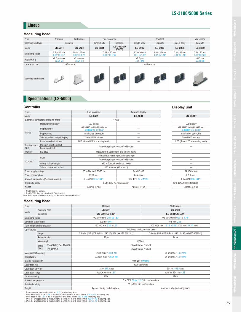
LS-3100/5000 Series
Measuring head
Type Standard Wide range Fine measuring Standard Wide range
Scanning head type Separate Single-body Separate Single-body Separate Single-body Separate
Model LS-5041 LS-5121 LS-3034LS-3033SO
(8073)LS-3032 LS-3033 LS-3036 LS-3060
Measuring range 0.2 to 40 mm 0.01" to 1.57"
0.8 to 120 mm 0.03" to 4.72"
0.08 to 30 mm 0.003" to 1.18"
0.3 to 30 mm 0.01" to 1.18"
0.5 to 30 mm 0.02" to 1.18"
0.3 to 30 mm 0.01" to 1.18"
0.8 to 60 mm 0.03" to 2.36"
Repeatability ±0.3 μm max. ±0.01 Mil
±1 μm max. ±0.04 Mil
±0.3 μm ±0.01 Mil
±0.5 μm ±0.02 Mil
Laser scan rate 1200 scans/s 400 scans/s
Scanning head shape
Display unitController
Type Built-in display Separate display —
Model LS-5501 LS-5001 LS-D501*2
Number of connectable scanning heads 4 max. —
Display
Measurement display LCD display — LCD display
Display range -99.99995 to 999.99995 mm -0.99999" to 9.99999" — -99.99995 to 999.99995 mm
-0.99999" to 9.99999"
Display units mm/inches selectable — mm/inches selectable
Tolerance check output display 7-level LCD indicator — 7-level LCD indicator
Laser emission indicator LCD (Green LED at scanning head) — LCD (Green LED at scanning head)
Terminal block input
Program selection inputNon-voltage input (contact/solid state) —
Laser stop input
Interface RS-232C Measurement data output and control output —
I/O board*1
InputTiming input, Reset input, Auto-zero input
Non-voltage input (contact/solid state) —
Analog voltage output ±10 V Output impedance: 100 Ω —
7-level comparator output 100 mA max. (40 V max.) —
Power supply voltage 85 to 264 VAC, 50/60 Hz 24 VDC ±10 24 VDC ±10%
Power consumption 85 VA max. 1.4 A max. 0.6 A max.
Ambient temperature (No condensation) 0 to 40°C 32 to 104°F 0 to 45°C 32 to 113°F 0 to 40°C 32 to 104°F
Relative humidity 35 to 85%, No condensation 35 to 85%, No condensation
Weight Approx. 3.7 kg Approx. 1.1 kg Approx. 0.7 kg
*1 The I/O board is optional.*2 The LS-D501 does not comply with EMC directive.Note: BCD output is available as an option. Please inquire with KEYENCE.
Measuring head
Type Standard Wide range
ModelScanning head LS-5041 LS-5121
Controller LS-5501/LS-5001 LS-5501/LS-5001
Measuring range 0.2 to 40 mm 0.01" to 1.57" 0.8 to 120 mm 0.03" to 4.72"
Minimum target width 0.2 mm 0.01" 0.8 mm 0.03"
Transmitter/receiver distance 160 ±40 mm 6.30" ±1.57" 400 ±100 mm 15.75" ±3.94", 1000 mm 39.37" max. *1
Light source Visible red semiconductor laser
Output 0.8 mW (FDA (CDRH) Part 1040.10), 130 μW (IEC 60825-1) 0.6 mW (FDA (CDRH) Part 1040.10), 45 μW (IEC 60825-1)
Pulse duration 63 μs 14 μs
Wavelength 670 nm
Laser Class
FDA (CDRH) Part 1040.10 Class II Laser Product
IEC 60825-1 Class 2 Laser Product
Measurement accuracy ±2 μm max.*2 ±0.08 Mil ±8 μm max.*3 ±0.32 Mil
Repeatability ±0.3 μm max.*4 ±0.01 Mil ±1 μm max.*5 ±0.04 Mil
Display repeatability 0.05 μm 0.002 Mil
Laser scan rate 1200 scans/sec
Laser scan velocity 121 m 397.0'/sec 504 m 1653.5'/sec
Laser scan range Approx. 46 mm 1.81" Approx. 124 mm 4.88"
Enclosure rating IP64 IP65
Ambient temperature 0 to 50°C 32 to 122°F, No condensation
Relative humidity 35 to 85%, No condensation
Weight Approx. 1.4 kg (including base) Approx. 5.5 kg (including base)
*1 The measurable area is within 800 mm 31.5" from the transmitter.*2 When a round rod 10 mm 0.39" in diameter is measured in a 10 mm x 20 mm 0.39" x 0.79" measuring area.*3 When a rod 40 mm 1.57" in dia. is measured in a 40 mm x 80 mm 1.57" x 3.15" measuring area. *4 When the average number of measurements is set to 768 in a 10 mm x 20 mm 0.39" x 0.79" measuring area.*5 When the average number of measurements is set to 768 in a 40 mm x 80 mm 1.57" x 3.15" measuring area.
Lineup
Specifi cations (LS-5000)
59
LK-G5000 SeriesLK-G3000 Series
LJ-G SeriesSI-F1000 Series
SI-F80R SeriesLS-7000 Series
LS-3100/5000 SeriesTM
-3000 SeriesIM
-6500 SeriesLK Series
LJ-V7000 SeriesLT-9000 Series

3-ø5.5 3-ø5.5 ø0.22"mounting hole
2-M42-M4
24
5
24
10
15
24
15
10
49
5
5
(9) (9)
1717
17
2134
13
40
71 97
85
5555
77
8080
77
7686
1817
16.5
17
24
17.5
5
5
76
32
86
85
360
180
160
105 105
135135
97 71 1717
4-M4, effective depth: 10
4-ø4.5 through-hole
Measuring areaMounting hole
4-ø4.5 ø0.18" through-holeø8 ø0.31" spot facing, d=4.5 d=0.18"
4-M4effective depth: 10
1.34"
0.83"
ø0.22"
1.26"4.13"
4.13"
0.67"
0.67"
0.20"
0.20"
0.94"
5.31" 5.31"14.17"(0.35") (0.35")
0.67"0.67"
0.67"0.67"
2.80"2.80" 3.82" 3.82"
0.20"
0.20"
0.94"
0.20"
2.99"3.39"
0.69"
0.65"
0.67"
3.39"2.99"
0.39"
3.03"6.30"
3.03"
3.35" 3.35"7.09"
ø0.18" 0.39"
0.39"3.15" 3.15"
1.93"
0.94" 1.57"
0.59" 0.59"
2.17" 2.17"
0.39"
0.94"
0.20"
0.51"
4-M6, effective depth: 10
4-M4, effective depth: 6 4-M4, effective depth: 6
3-ø7.5mounting hole
3-ø7.5mounting hole
Measuring area
4-ø6.5 through-holeø14 spot facing, d=7
8-ø4.5 through-holeø10 spot facing, d=5
4-M4effective depth: 10
35
10
10
2525
20*55
(16) (16)
10
35
150 150
706288272
132 21.5
35
10
112 221.5 221.521.5
35
620
32
145
168180
6
168120
89
17
180
125 1515
200200
155 175
27.5
40
29.5
6545
*20 ±2 mm at the measuring center
1.38"
0.39" 0.98"
1.16" 0.79"
7.09" 6.61"
0.24"
1.26"
4.92"
10.71"27.80"
0.39"
1.38"
0.85" 4.41" 8.72" 8.72" 5.20"
11.34"
0.59" 0.59"5.71"
0.24" 1.08"
6.61"
7.09"
1.57"
3.50"
0.67"
6.89"
4.72"
7.87" 7.87"
6.10"
2.56"
1.77"
0.98"
ø0.26"
ø0.55"
ø0.30" ø0.30"
ø0.18"
ø0.39"
0.39"0.39"
0.39"
1.38"
1.38"
0.85"
(0.63")(0.63")
0.24"0.24"
d=0.20"
d=0.28"0.39"
2.17"
0.79"±0.08"
0.79"
5.91"5.91"
Specifi cations (LS-3100)
Dimensions
Standard controller/2-head controller
Type Fine measuring Standard Wide rangeScanning head type Single-body Separate Single-body Separate Single-body Separate
ModelScanning head LS-3034 LS-3033SO(8073) LS-3032 LS-3033 LS-3036 LS-3060
Standard controller/ 2-head controller LS-3100/LS-3100D
Measuring range
Scanning head 0.08 to 30 mm*1
0.003" to 1.18"0.08 to 30 mm*1
0.003" to 1.18"0.3 to 30 mm0.01" to 1.18"
0.5 to 30 mm0.02" to 1.18"
0.3 to 30 mm0.01" to 1.18"
0.8 to 60 mm0.03" to 2.36"
Controller mm/inch selectableMinimum target width 0.08 mm 0.003" 0.08 mm 0.003" 0.3 mm 0.01" 0.5 mm 0.02" 0.3 mm 0.01" 0.8 mm 0.03"
T and R distance*4 60 mm 2.36"
120 mm 4.72" (Fixed)
60 mm 2.36"
120 ±40 mm 4.72"±1.57"
60 mm 2.36"
200 ±50 mm7.87"±1.97"
Light source Invisible infrared semiconductor laser Visible red semiconductor laser
Output 3.0 mW (FDA), 55 μW (IEC) 0.5 mW (FDA), 35 μW (IEC)
0.5 mW (FDA), 20 μW (IEC)
Wavelength 780 nm 670 nmPulse duration 111 μs 55.6 μs
Laser ClassFDA (CDRH) Part 1040.10 Class I Laser Product Class II Laser Product
IEC 60825-1 Class 1 Laser ProductMeasurement accuracy ±2 μm max.*2 ±0.08 Mil ±3 μm max.*3 ±0.12 MilRepeatability (number of averaging measurements: 512) ±0.3 μm ±0.01 Mil ±0.5 μm ±0.02 MilDisplay resolution 0.1 μm 0.004 MilLaser scan rate 400 scans/sLaser scan velocity 63 m 206.7'/s 126 m 413.4'/sLaser scan range Approx. 33 mm 1.30" Approx. 65 mm 2.56"Measured value Main display: 7-segment green LED (8 digits) Sub display: 16 character x 2 line LCD (Backlight color: yellow-green)Minimum display unit 0.1 μm 0.004 Mil/0.2 μm 0.008 MilDisplay range -999.9999 to 9999.9999Target position indicator Green LED (7 levels)Comparator output indicator Green LED x 3 (HI/GO/LO)Laser emission indicator Green LED x 2 (HEAD 1/HEAD 2)
Terminal block I/O
Control I/OHold synchronous, LASER REMOTE, PROGRAM SELECT (Program Nos. 1 to 5)
Non-voltage input (contact/solid state)Analog voltage ±6 V, Output impedance: 0 ΩContact output Relay output: 3PST-NO contact, 250 VAC, 2 A (resistive load)
36-pin connector I/O
Control inputHold synchronous, AUTO ZERO SET/RESET, PROGRAM SELECT (Program Nos. 1 to 5)
TTL level, negative logicControl output 7-level/3-level 40 mA max. (30 V max.)
Interface port RS-232C/GP-IB (optional)/BCD (optional)Power supply 85 to 264 VAC, 50/60 HzPower consumption 40 VA max.
Ambient temperature
Scanning head 0 to 45°C 32 to 113°F 0 to 40°C 32 to 104°FController 0 to 45°C 32 to 113°F
Relative humidity 35 to 85%, No condensation
WeightScanning head*3 0.8 kg T: 0.5 kg
R: 0.4 kg 0.8 kg T: 0.5 kgR: 0.4 kg 0.8 kg Approx. 2.5 kg
(base included)Controller Approx. 4.6 kg
*1 When the outer diameter is measured.*2 When a rod 10 mm 0.39" in diameter is measured in a 2 x 20 mm 0.08" x 0.79", 4 x 20 mm 0.16" x 0.79", or 10 x 20 mm 0.39" x 0.79" measuring area.*3 When measuring a rod 20 mm 0.79" in diameter in a 20 x 40 mm 0.79" x 1.57" measuring area.*4 ‘T’ indicates a transmitter, ‘R’ indicates a receiver.
Scanning heads
LS-5041
Unit: mm inch
LS-5121
LS-3100/5000 Series
60

LS-3100/5000 Series
132 124.5
108 495
163
Mounting screw
(Mounting bracket dimension)
Panel thickness: 1.2 to 4.0
Mounting bracket
149
4.25"
6.42"0.20" 1.93"
4.90"
0.05" to 0.16"
5.87"
5.20"
35.4
37.3
1
9980
170
116
130140152(External mounting bracket)
Approx.
5.98"5.51" 5.12"
4.57"
6.69"
3.15" 3.90"
1.39"
1.47"
0.04"
ø0.20"4x ø5
125
159 min.
+1 0
156 +1 0
173 min.6.81"
6.26"6.14"+0.04" 0
4.92"+0.04" 0
41
80
197 187
126
180 230
148
Approx.
4.96"
7.76" 7.36"
7.09"
5.83"
9.06"
1.61"
3.15"
(30)(34)
Measuring area
32
(7)5
6
3826
(12)
83
72
56
210124
220
30
19.5
4-ø4.5mounting hole
60
ø0.18"
(0.47")
3.27"
2.83"
2.20"
0.24"
1.50"1.02"
4.88"0.20" 8.27"
8.66" (0.28")
1.26"
(1.34)(1.18)
1.18"
0.77"2.36"
30 34
3034
65.5 65.5
1.65" 42
843
M4
22
10
6
2121
33
32
5
32
(7)
12
18
3-ø5.5 ø0.22" mounting hole3-ø5.5 mounting hole
4-M4
4-M4 4-M4
216 (±50)
15
27
180.5 7.11"
60
6
4.33"110
98.5
60
77 200 (±50)
167 85
20
24
62
100
12
18
115.5152 70115.5
220.5 138.5
5
98.5
110
(7)
Measuring area
4-ø4.5 ø0.18" through-holeø8 spot facing, d=4.5
479 18.86"
0.59"
1.18"
1.18"
1.06"1.34"
1.34"
ø0.22"
1.30"
0.83"0.24"
6.57"
3.03"
0.31" 3.94"
8.50" (±1.97")
1.69"
3.35"0.20"
1.26"
(0.28")(0.28")
0.47"
0.71"5.98" 4.55" 4.55" 2.76"
0.71"
0.47"
5.45"8.68"
0.20"
1.26"
0.24"0.79" 0.83"
2.44"
0.94"
4.33"3.88"3.88"
2.36"
ø0.31" d=0.18"
2.58" 2.58"0.39"
0.87"
7.87" (±1.97")
2.36"98.5
8
(30)(34)
12.5
38
(25.5)105.5
12.5
(25.5)
6(30)(34)
24
30
92
TransmitterReceiver
46
120 (±40)136 (±40)
331 (±40)
105.5
38
92
(7)
8546
73.5
73.5
6
8551
60
Measuring area
4-ø5.5mounting hole 4-ø5.5
mounting hole
0.49" 0.49"
1.50"
(1.00")
1.50"
(1.00")
(1.18")
2.00" 3.35"2.89"
1.81"
0.24" 0.312.36"
13.03" (±1.57")5.35" (±1.57")
4.72" (±1.57")3.62" 3.62"
(0.28")
(1.34")
(1.18")0.24"
1.81"
2.89"
3.35"
0.94"
1.18"
(1.34")
4.15" 4.15"
ø0.22" ø0.22"
34
R11 R7.5
ø20
ø16
13
25
111123
330
238176
122
20
244
230
36Approx. 47
4.84" 4.37"
12.99"
9.37"
1.42"
R0.43" R0.30"
9.61"
9.06"
4.80"
0.79"
6.93"1.34"
1.85"ø0.63"
ø0.79"
0.51"
0.98"
* Distance is fi xed for LS-3033SO (8073).
LASER RADIATION-DO NOTSTARE INTO BEAM
SEMICONDUCTOR LASER 670nmMAXIMUM OUTPUT 0.5mWCLASS II LASER PRODUCT
CAUTION
Controllers
LS-3100 (LS-3100D)
LS-5041 LS-5121 LS-3036/3060
Display unit
LS-D501
Separate display controller
LS-5001
Scanning heads
LS-3032/3034/3036 LS-3060
Built-in display controller
LS-5501
Panel cutout
LS-3033/3033SO(8073)
61
LK-G5000 SeriesLK-G3000 Series
LJ-G SeriesSI-F1000 Series
SI-F80R SeriesLS-7000 Series
LS-3100/5000 SeriesTM
-3000 SeriesIM
-6500 SeriesLK Series
LJ-V7000 SeriesLT-9000 Series

High-speed 2D Measurement Sensor
TM-3000 Series
Features Multi-point 2D measurement Tilt correction for inline measurement High-speed sampling of 5.5 ms
Expert Engineering SitesA new site with answers to all of your diffi cult measurement application questions
www.keyence.com
Because the system works in two dimensions it can...
Position correction function [edge correction/pattern correction]
Simultaneously measure dimensions that require both X and Y values.
In addition, inspection time is reduced due to the elimination of motion
components.
Automatically corrects misalignments and tilt of the target which is directly
linked to measurement errors. Can measure accurately even when
positioning is diffi cult or objects are conveyed in random orientations.
: Hole diameter
: Center pitch
: Intersection point coordinates
: Radius
: Width
: Angle
: Perpendicular distance
: Area
Perpendicular distance
Intersection point coordinates
Center pitch
Example of measurementArea
Radius
Hole diameter
Angle
WidthCorrection
Outer diameter measurement area Position
correction area
Because the measurement area autotracks according to the position and tilt of objects within the compensation area, it can be measured accu-rately.
Master image Measured image
Position correction area Outer
diameter measurement area after correction
NEW
TM-3000 Series
62
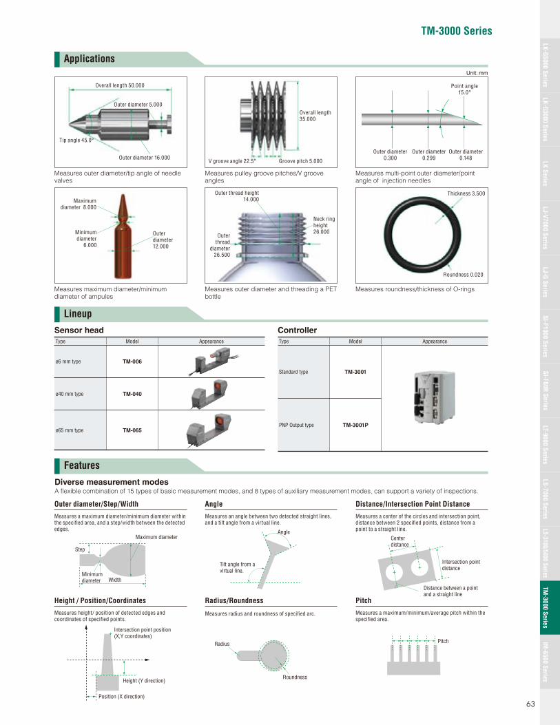
TM-3000 Series
Lineup
Features
Applications
Measures outer diameter/tip angle of needle valves
Measures maximum diameter/minimum diameter of ampules
Measures multi-point outer diameter/point angle of injection needles
Measures roundness/thickness of O-rings
Measures pulley groove pitches/V groove angles
Measures outer diameter and threading a PET bottle
Outer diameter 16.000
Tip angle 45.0°
Outer diameter 5.000
Overall length 50.000
Overall length35.000
V groove angle 22.5° Groove pitch 5.000
Outer diameter 0.300
Outer diameter 0.299
Outer diameter 0.148
Point angle 15.0°
Maximum diameter 8.000
Outer diameter12.000
Minimum diameter
6.000
Outer thread height 14.000
Outer thread
diameter 26.500
Neck ring height 26.000
Thickness 3.500
Roundness 0.020
Diverse measurement modesA fl exible combination of 15 types of basic measurement modes, and 8 types of auxiliary measurement modes, can support a variety of inspections.
Maximum diameter
WidthMinimum diameter
Step
Outer diameter/Step/Width
Measures a maximum diameter/minimum diameter within the specifi ed area, and a step/width between the detected edges. Angle
Tilt angle from a virtual line.
Angle
Measures an angle between two detected straight lines, and a tilt angle from a virtual line.
Intersection point distance
Center distance
Distance between a point and a straight line
Distance/Intersection Point Distance
Measures a center of the circles and intersection point, distance between 2 specifi ed points, distance from a point to a straight line.
Position (X direction)
Intersection point position (X,Y coordinates)
Height (Y direction)
Height / Position/Coordinates
Measures height/ position of detected edges and coordinates of specifi ed points.
Roundness
Radius
Radius/Roundness
Measures radius and roundness of specifi ed arc.
Pitch
Pitch
Measures a maximum/minimum/average pitch within the specifi ed area.
Sensor head
Type Model Appearance
ø6 mm type TM-006
ø40 mm type TM-040
ø65 mm type TM-065
Controller
Type Model Appearance
Standard type TM-3001
PNP Output type TM-3001P
Unit: mm
63
LK-G5000 SeriesLK-G3000 Series
LJ-G SeriesSI-F1000 Series
SI-F80R SeriesLS-7000 Series
LS-3100/5000 SeriesTM
-3000 SeriesIM
-6500 SeriesLK Series
LJ-V7000 SeriesLT-9000 Series
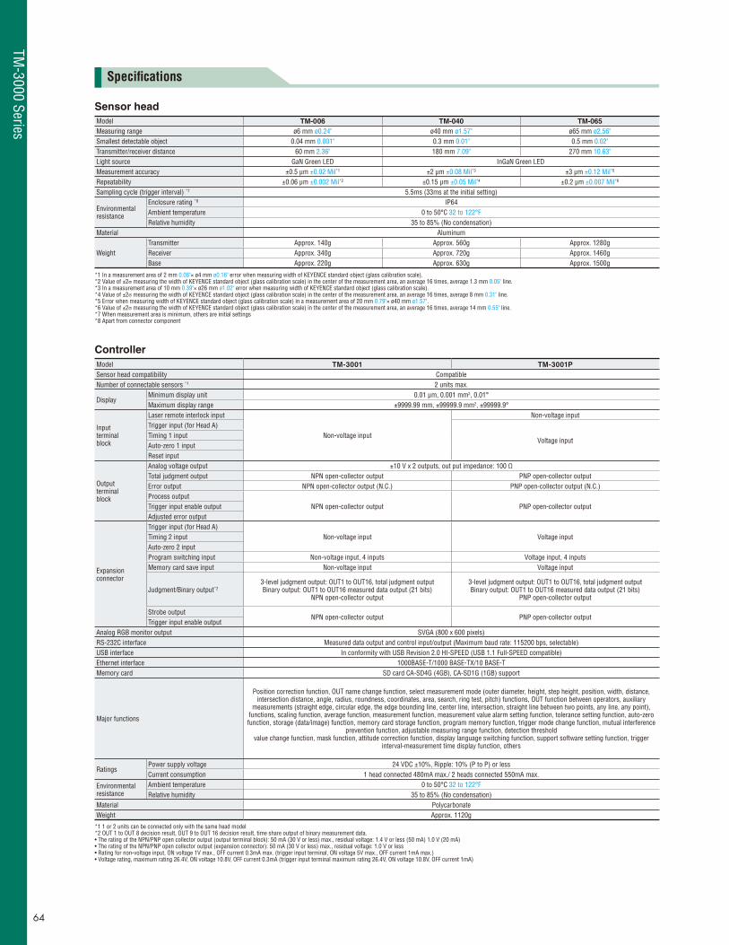
Specifi cations
Sensor head
Model TM-006 TM-040 TM-065
Measuring range ø6 mm ø0.24" ø40 mm ø1.57" ø65 mm ø2.56"Smallest detectable object 0.04 mm 0.001" 0.3 mm 0.01" 0.5 mm 0.02"Transmitter/receiver distance 60 mm 2.36" 180 mm 7.09" 270 mm 10.63"Light source GaN Green LED InGaN Green LEDMeasurement accuracy ±0.5 μm ±0.02 Mil*1 ±2 μm ±0.08 Mil*3 ±3 μm ±0.12 Mil*5
Repeatability ±0.06 μm ±0.002 Mil*2 ±0.15 μm ±0.05 Mil*4 ±0.2 μm ±0.007 Mil*6
Sampling cycle (trigger interval) *7 5.5ms (33ms at the initial setting)
Environmental resistance
Enclosure rating *8 IP64Ambient temperature 0 to 50°C 32 to 122°F Relative humidity 35 to 85% (No condensation)
Material Aluminum
WeightTransmitter Approx. 140g Approx. 560g Approx. 1280gReceiver Approx. 340g Approx. 720g Approx. 1460gBase Approx. 220g Approx. 630g Approx. 1500g
*1 In a measurement area of 2 mm 0.08"× ø4 mm ø0.16" error when measuring width of KEYENCE standard object (glass calibration scale).*2 Value of ±2σ measuring the width of KEYENCE standard object (glass calibration scale) in the center of the measurement area, an average 16 times, average 1.3 mm 0.05" line.*3 In a measurement area of 10 mm 0.39"× ø26 mm ø1.02" error when measuring width of KEYENCE standard object (glass calibration scale).*4 Value of ±2σ measuring the width of KEYENCE standard object (glass calibration scale) in the center of the measurement area, an average 16 times, average 8 mm 0.31" line.*5 Error when measuring width of KEYENCE standard object (glass calibration scale) in a measurement area of 20 mm 0.79"× ø40 mm ø1.57".*6 Value of ±2σ measuring the width of KEYENCE standard object (glass calibration scale) in the center of the measurement area, an average 16 times, average 14 mm 0.55" line.*7 When measurement area is minimum, others are initial settings*8 Apart from connector component
Controller
Model TM-3001 TM-3001P
Sensor head compatibility CompatibleNumber of connectable sensors *1 2 units max.
DisplayMinimum display unit 0.01 μm, 0.001 mm2, 0.01°Maximum display range ±9999.99 mm, ±99999.9 mm2, ±99999.9°
Inputterminalblock
Laser remote interlock input
Non-voltage input
Non-voltage inputTrigger input (for Head A)
Voltage inputTiming 1 inputAuto-zero 1 inputReset input
Outputterminalblock
Analog voltage output ±10 V x 2 outputs, out put impedance: 100 ΩTotal judgment output NPN open-collector output PNP open-collector outputError output NPN open-collector output (N.C.) PNP open-collector output (N.C.)Process output
NPN open-collector output PNP open-collector outputTrigger input enable outputAdjusted error output
Expansionconnector
Trigger input (for Head A)Non-voltage input Voltage inputTiming 2 input
Auto-zero 2 inputProgram switching input Non-voltage input, 4 inputs Voltage input, 4 inputsMemory card save input Non-voltage input Voltage input
Judgment/Binary output*23-level judgment output: OUT1 to OUT16, total judgment outputBinary output: OUT1 to OUT16 measured data output (21 bits)
NPN open-collector output
3-level judgment output: OUT1 to OUT16, total judgment outputBinary output: OUT1 to OUT16 measured data output (21 bits)
PNP open-collector output
Strobe outputNPN open-collector output PNP open-collector output
Trigger input enable outputAnalog RGB monitor output SVGA (800 x 600 pixels)RS-232C interface Measured data output and control input/output (Maximum baud rate: 115200 bps, selectable)USB interface In conformity with USB Revision 2.0 HI-SPEED (USB 1.1 Full-SPEED compatible)Ethernet interface 1000BASE-T/1000 BASE-TX/10 BASE-TMemory card SD card CA-SD4G (4GB), CA-SD1G (1GB) support
Major functions
Position correction function, OUT name change function, select measurement mode (outer diameter, height, step height, position, width, distance, intersection distance, angle, radius, roundness, coordinates, area, search, ring test, pitch) functions, OUT function between operators, auxiliary
measurements (straight edge, circular edge, the edge bounding line, center line, intersection, straight line between two points, any line, any point), functions, scaling function, average function, measurement function, measurement value alarm setting function, tolerance setting function, auto-zero function, storage (data/image) function, memory card storage function, program memory function, trigger mode change function, mutual interference
prevention function, adjustable measuring range function, detection threshold value change function, mask function, attitude correction function, display language switching function, support software setting function, trigger
interval-measurement time display function, others
RatingsPower supply voltage 24 VDC ±10%, Ripple: 10% (P to P) or lessCurrent consumption 1 head connected 480mA max./ 2 heads connected 550mA max.
Environmentalresistance
Ambient temperature 0 to 50°C 32 to 122°F Relative humidity 35 to 85% (No condensation)
Material Polycarbonate Weight Approx. 1120g
*1 1 or 2 units can be connected only with the same head model *2 OUT 1 to OUT 8 decision result, OUT 9 to OUT 16 decision result, time share output of binary measurement data. • The rating of the NPN/PNP open collector output (output terminal block): 50 mA (30 V or less) max., residual voltage: 1.4 V or less (50 mA) 1.0 V (20 mA)• The rating of the NPN/PNP open collector output (expansion connector): 50 mA (30 V or less) max., residual voltage: 1.0 V or less• Rating for non-voltage input, ON voltage 1V max., OFF current 0.3mA max. (trigger input terminal, ON voltage 5V max., OFF current 1mA max.) • Voltage rating, maximum rating 26.4V, ON voltage 10.8V, OFF current 0.3mA (trigger input terminal maximum rating 26.4V, ON voltage 10.8V, OFF current 1mA)
TM-3000 Series
64
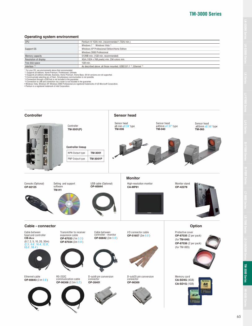
TM-3000 Series
Operating system environment
CPU Pentium III 1GHz min. (recommended 1.7GHz min.)
Support OSWindows 7 *1 Windows Vista *2
Windows XP Professional Edition/Home EditionWindows 2000 Professional
Memory capacity 512MB min. (1GB min. recommended) Resolution of display XGA (1024 x 768 pixels) min, 256 colors min.Free disk space 1GB min.Interface *3 As described above, all those mounted, USB2.0/1.1 *4, Ethernet *5
* For your OS, use environments above that recommended. *1 Supports all editions Home Premium, Professional, Ultimate.*2 Supports all editions Ultimate, Business, Home Premium, Home Basic. 64 bit versions are not supported. *3 Communicate selecting any of them. Simultaneous communication is not possible. *4 Connection through a USB hub is not included in the guarantee. *5 Connection to LAN and connection via a router is not included in the guarantee. • Windows Vista, Windows XP, Windows 2000 Professional are registered trademarks of US Microsoft Corporation. • Pentium is a registered trademark of intel Corporation.
High-resolution monitorCA-MP81
Monitor standOP-42278
ControllerTM-3001(P)
Controller lineup
Console (Optional)OP-82125
Setting and support softwareTM-H1
USB cable (Optional)OP-66844
Sensor head ø40mm ø1.57" typeTM-040
Sensor head ø65mm ø2.56" typeTM-065
Cable between head and controller CB-A××
(0.7, 2, 5, 10, 20, 30m)(2.3', 6.6', 16.4', 32.8', 65.6', 98.4')
Transmitter to receiver expansion cable OP-87033 (1m 3.3')OP-87034 (3m 9.8')
Cable between controller - monitor OP-66842 (3m 9.8')
I/O connector cable OP-51657 (3m 9.8')
Protective coverOP-87035 (2 per pack)(for TM-040)OP-87036 (2 per pack)(for TM-065)
Ethernet cableOP-66843 (3 m 9.8')
RS-232C communication cable OP-96368 (2.5m 8.2')
D-sub9 pin conversion connectorOP-26401
D-sub25 pin conversion connectorOP-96369
Memory cardCA-SD4G (4GB)CA-SD1G (1GB)
NPN Output type TM-3001
PNP Output type TM-3001P
Sensor head ø6 mm ø0.24" typeTM-006
Controller Sensor head
Monitor
Cable - connector Option
65
LK-G5000 SeriesLK-G3000 Series
LJ-G SeriesSI-F1000 Series
SI-F80R SeriesLS-7000 Series
LS-3100/5000 SeriesTM
-3000 SeriesIM
-6500 SeriesLK Series
LJ-V7000 SeriesLT-9000 Series

8
29
58.5
5
88
97.5
3-ø5.5 (mounting hole)
Cable length: 235
76.5
20
17.5
180
Measurement area
ø40
65.5±0.6
9047
88
5
97.5
3-ø5.5 (mounting hole)94.8
6.5
2.8
Cable length: 500
Cable length: 175
When minimum bend R
When minimum bend R
Front surface of receiver
4-M3 effective depth 3.5
41.5
48
7 48
6231±0.3
1.22"±0.01"
2.58"±0.02"
2525
5555
4-ø4.5 ø0.18" cut ø8 ø0.31depth 4.5 4-M4
6
50
Measurement area
50
Front surface of transmitter
4-M3 effective depth 3.548 7
48
41.5
4-M4 effective depth 8 0.32"
39.8145 161
306
115 1155.5
6
50
2-M4 effective depth 6 0.24" 2-M4 effective depth 6 0.24"
31
34 103 103.5 25
31
20
0.14"
0.28"
0.28"1.89"
1.89"
1.63"2.44"
1.97"1.97"
0.24"
0.79"
0.79"
2.17"
3.73"
3.84"
3.84"
3.46" 3.46"
0.20"
1.57" 12.05"
4.53" 4.53"5.71" 6.34"
1.34" 4.06" 4.07" 0.98"0.22"
1.97"
1.22"
0.24"
0.20"
0.11"
19.69"
6.89"
9.25"7.09"
0.31"2.30"
1.14"
0.69"
3.54"1.85"
0.26"
2.17"
3.01"
0.98" 0.98"
1.89"
1.89"
1.63"
0.14"
ø0.22"
ø1.57"
ø0.22"
1.22"
0.24"
0.24"
ø0.24"
2-ø4 ø0.16"(mounting hole)3-ø4 ø0.16"(mounting hole)Measurementarea
Cable length 100
Cable length 190
Cable length 500
ø8 ø0.31 spot facing, 4.5
4-ø4.5 ø0.18" through-hole 4-M4 through-hole
2-M4 through-hole
2-M4 through-hole
1.02"
4
261.02"
4.50.18"
16±0.2 0.62"±0.007"
40±0.21.57"±0.007" ø6
5.59"
2128.35"
701422.76"
25 25
15 150.59" 0.59"
486
2.20"
18 0.71"
46 561.81"
0.94" 2624
1.81"
40.16"
19.69"
7.48"
56 462.20"
126 250.98"4.96"1.89"
1.38"
2.01"76 51
2.99" 1.26"328
1.26"
4.53"45115
1.77"
361.42"
1.57" 0.71"1.85"9240 1847
3.62"
16160.63" 0.63"
3.5 3.50.14"0.14" 3.19"
38811.50"
4
(227)(8.94")
6
2-M4 Effective depth 52-M4 Effective depth 5
301.18"
602.36"
Base 35
0.98" 0.98"
0.16"
0.16"
3.94"
Dimensions
Sensor heads
TM-006
Unit: mm inch
TM-040
TM-3000 Series
66
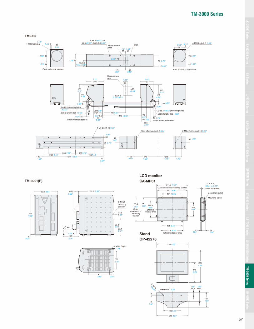
TM-3000 Series
80
70
17
4 x M4 Depth: 6 0.24"
35.9
(15)
(60)
135.5
8
65.3
83.3
DIN rail mounting position
92.5
153
6
4-M3 Depth 3.5
Front surface of receiver
44
76
9 76
4-ø5.5 ø0.22" cut ø9.5 ø0.37" depth 5.5 0.22"
4-M4
9447±0.6
3535
65115
70
12
Measurementarea
70
82±0.8
ø65
160
2709.5 11.5
6633.5
66.5
115
130
5
120
130
Measurementarea
3-ø5.5 ø0.22"(mounting hole)
3-ø5.5 (mounting hole)
Cable length: 500Cable length: 175
Cable length: 420
129.7 97
When minimum bend R 19When minimum bend R
205
8.7
176 131.553 44
4747
2-M4 effective depth 6 0.24" 2-M4 effective depth 6 0.24"
4-M5 Depth 10
12
70
200 130190240
43049.717
4-M3 Depth 3.5
76
76
44
9
Front surface of transmitter
30
1.41"
3.28"
2.57"
0.67"3.15"
5.33"0.59"
0.32"
2.36"
2.76"
0.24"
6.02"
3.64"
0.35"0.14"
2.99"
3.70"
1.73"
2.99"
1.85"±0.02"
4.53"
1.38" 1.38"
2.56"
2.76"2.76"
0.47"
0.35" 0.14"
2.99"
1.73"
2.99"
0.79"
0.20"
6.89"
0.47"
0.39"
1.85"
0.20"
2.60"
2.62"
0.75"
16.53"
1.32"0.45"0.34" 0.37"
5.12"5.12"
4.72"
3.82"1.18"5.11"
ø2.56"
4.53"
19.69" 6.30"
10.63"
ø0.22"
3.23"±0.03"
1.85"
1.73"5.18"6.93"2.09"
5.12"7.87"9.45"
1.96"
7.48"16.93"
0.67"
2.76"
241.2
Outer dimension of mounting bracket
172.4 Effective display area
129.8 191.2 7.53" 5.11"
9.50"
9.06"
15.95"
6.14"
6.79"
7.09"180
230
151
156
106
6 34
Mounting screw
Mounting bracket
Panel thickness
Outerdimension of
mountingbracket
Effectivedisplay area
4.17"
0.24" 1.34"
1.0 to 4.0 0.04" to 0.16"
9.06"
9.29"
5.75"
0.20"
0.32"
8.27"
5.12"
0.85" 2.62"
4.37"
236
230
210
146
66.5
2- R2.5R0.01"
8
5
130
21.5
111
TM-065
TM-3001(P)
LCD monitor
CA-MP81
Stand
OP-42278
67
LK-G5000 SeriesLK-G3000 Series
LJ-G SeriesSI-F1000 Series
SI-F80R SeriesLS-7000 Series
LS-3100/5000 SeriesTM
-3000 SeriesIM
-6500 SeriesLK Series
LJ-V7000 SeriesLT-9000 Series
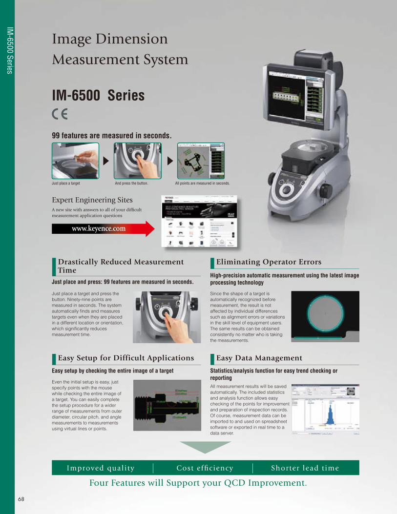
Image Dimension Measurement System
Just place a target and press the
button. Ninety-nine points are
measured in seconds. The system
automatically fi nds and measures
targets even when they are placed
in a different location or orientation,
which signifi cantly reduces
measurement time.
Since the shape of a target is
automatically recognized before
measurement, the result is not
affected by individual differences
such as alignment errors or variations
in the skill level of equipment users.
The same results can be obtained
consistently no matter who is taking
the measurements.
Even the initial setup is easy, just
specify points with the mouse
while checking the entire image of
a target. You can easily complete
the setup procedure for a wider
range of measurements from outer
diameter, circular pitch, and angle
measurements to measurements
using virtual lines or points.
All measurement results will be saved
automatically. The included statistics
and analysis function allows easy
checking of the points for improvement
and preparation of inspection records.
Of course, measurement data can be
imported to and used on spreadsheet
software or exported in real time to a
data server.
IM-6500 Series
Expert Engineering SitesA new site with answers to all of your diffi cult measurement application questions
www.keyence.com
Drastically Reduced Measurement Time
Eliminating Operator Errors
Easy Setup for Difficult Applications Easy Data Management
Just place a target And press the button. All points are measured in seconds.
Cost effi ciency
Four Features will Support your QCD Improvement.
Shorter lead t imeImproved quali ty
Just place and press: 99 features are measured in seconds.
Easy setup by checking the entire image of a target Statistics/analysis function for easy trend checking or reporting
High-precision automatic measurement using the latest image processing technology
99 features are measured in seconds.
IM-6500 Series
68
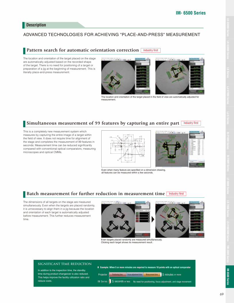
IM- 6500 Series
ADVANCED TECHNOLOGIES FOR ACHIEVING "PLACE-AND-PRESS" MEASUREMENT
Pattern search for automatic orientation correction
Simultaneous measurement of 99 features by capturing an entire part
Batch measurement for further reduction in measurement time
The location and orientation of the target placed on the stage
are automatically adjusted based on the recorded shape
of the target. There is no need for positioning of a target or
preparation of a jig at the beginning of measurement. This is
literally place-and-press measurement.
This is a completely new measurement system which
measures by capturing the entire image of a target within
the fi eld of view. It does not require time for alignment of
the stage and completes the measurement of 99 features in
seconds. Measurement time can be reduced signifi cantly
compared with conventional optical comparators, measuring
microscopes and optical CMMs.
The dimensions of all targets on the stage are measured
simultaneously. Even when the targets are placed randomly,
it is unnecessary to align them in a jig because the location
and orientation of each target is automatically adjusted
before measurement. This further reduces measurement
time.
The location and orientation of the target placed in the fi eld of view are automatically adjusted for measurement.
Projector
In addition to the inspection time, the standby
time during product changeover is also reduced.
This helps improve the facility utilization ratio and
reduce costs.
SIGNIFICANT TIME REDUCTION
IM Ser ies
Positioning time Focus adjustment time Measurement time
No need for positioning, focus adjustment, and stage movement
5 minutes or more
5 seconds or less
Example: When 5 or more minutes are required to measure 10 points with an optical comparator
Description
Even when many feature are specifi ed on a dimension drawing, all features can be measured within a few seconds.
Even targets placed randomly are measured simultaneously. Clicking each target shows its measurement result.
Industry fi rst
Industry fi rst
Industry fi rst
69
LK-G5000 SeriesLK-G3000 Series
LJ-G SeriesSI-F1000 Series
SI-F80R SeriesLS-7000 Series
LS-3100/5000 SeriesTM
-3000 SeriesIM
-6500 SeriesLK Series
LJ-V7000 SeriesLT-9000 Series

Sub-pixel processing for measurement down to one hundredth or less of one pixel
Just click the points to be measured with the mouse
Automatic calculation of major statistical values. Group extraction is also easy.
Latest technologies to eliminate operator variationOne pixel of the light receiving element is divided into 100 or
more squares and used as a unit for shape recognition. This
allows high-resolution measurement in a wider fi eld of view.
The optical system is also taken into consideration to improve
accuracy.
Easy point and click programming interfaceTo set up feature inspections, just select the desired tool from
the menu and roughly specify the measurement points on the
screen with the mouse. Since the entire image of a target is
displayed, you can set details intuitively through simple mouse
operations.
Statistics/analysis functionsCritical statistical values required for inspection reports are
automatically calculated and displayed, including maximum,
minimum, average, σ, 3σ and CPK. You can also set various
conditions for group extraction for statistical, analysis, and
inspection records.
One pixel is divided into100 or more squares
Without sub-pixel processingThe target is measured by one pixel of the light receiving element.
One pixel of the light receiving element
With sub-pixel processingThe target is measured by one hundredth or less of a pixel of the light receiving element.
Best in its class
Select a desired measurement type from the menu.
Roughly specify the measurement points with the mouse.
Critical statistical values required for inspection reports are provided by default.
Groups can be extracted on various conditions.
System confi guration
AccessoriesSapphire glass for the measurement stage OP-86986
Normal glass: OP-86985
HeadIM-6010/6020
RGB
USB
LAN
Monitor
PC
Inkjet printer
Indicator, buzzer, etc.
Footswitch
ControllerIM-6501E
IM-6500 Series
70

IM- 6500 Series
Specifi cations
ModelController IM-6501E
Head IM-6010 IM-6020
Image pickup device 1" 6.6 mega pixel CMOSDisplay 10.4" LCD monitor (XGA: 1024 x 768)Light receiving lens Double telecentric lens
Field of viewWide-fi eld measurement mode ø100 mm ø3.94" ø100 mm ø3.94"High-precision measurement mode – ø25 mm ø0.98"
Minimum display unit 0.1 μm 0.004Mil
Repetition AccuracyWide-fi eld measurement mode ±1 μm ±0.04Mil ±1 μm ±0.04MilHigh-precision measurement mode – ±0.5 μm ±0.02Mil
Measurement accuracyWide-fi eld measurement mode ±5 μm*1 ±0.2Mil ±5 μm*1 ±0.2MilHigh-precision measurement mode – ±2 μm*2 ±0.08Mil
External remote input No-voltage input (with and without contact)External output Comparator output (OK/NG/FAIL) Relay output/rated load: 24 VDC 0.5A/ON resistance: 50 mΩ or less
InterfaceLAN RJ-45 (10BASE-T/100BASE-TX/1000BASE-T)USB 2.0 series A 6 ports (Front: 2, Rear: 4)
Record Hard disk drive 160 GB
Resistance to environmentOperating ambient temperature +10 to 35˚C +50 to 95°FOperating ambient humidity 20% to 80% RH (no condensation)
Illumination systemCoaxial transparent illumination Telecentric transparent illumination (green LED)Ring epi-illumination Four division ring illumination (white LED)
Z-axis stageMoving range along Z axis 30 mm 1.18"Withstand load 3 kg
Power supplyPower supply voltage 100 to 240 VAC 50/60 HzPower consumption 215 VA max.
WeightController Approx. 8 kgHead Approx. 24 kg Approx. 25 kg
*1 ±2σ in the range of ø80 mm ø3.15" from the center of the stage at the operating temperature range of +23±1.0°C +73.4±1.8°F degrees at the focused focal point position*2 ±2σ in the range of ø20 mm ø0.79" from the center of the stage at the operating temperature range of +23±1.0°C +73.4±1.8°F degrees at the focused focal point position
Measurement points 99 points max. (99 x 9 points possible when the measurement setting binding function is used)Pattern search (Profi le tracking function) XYθ (with 360° rotary position compensation)Registration of measurement confi guration 1000 or more*3
Basic measurement functionDistance measurement 8 types (point-point/line-point/line-line/circle-point/circle-line/circle-circle/circle/arc)Angle measurement ProvidedCalculation Provided
Virtual line function
Point Middle point/intersectionConjunction edge Line conjunction/circular conjunctionLine 6 types (midline/perpendicular line/parallel lines/tangent line/line passing through the point/approximate line)Circle Middle circle/approximate circle/auxiliary circle
Application tool
Pitch measurement Line/circumferenceWidth measurement Edge widthThickness measurement Thickness measurement/Gap measurement between inner and outer diametersSpecial tool Rounded corner/curved surface/oval/reticle/point position/perimeter
GD&TShape tolerance Straightness/circularity/profi leOrientation tolerance Squareness/parallelismPosition tolerance Point position/concentricity
Element tool
Point Point (on a line or arc)/maximum/minimum (rectangle, circle, arc)Line Line/centerlineCircle Circle/arcProfi le extraction ProvidedSpecial tool Automatic generation
Manual measurement ProvidedCoordinate system confi guration ProvidedBatch confi guration of tolerance ProvidedElement list editing ProvidedMeasurement setting data binding function Provided
*3 Depending on the measurement setting data and number of data pieces being stored
Dimensions
Head
IM-6010/6020
Controller
IM-6501E
Unit: mm inch
551
240
48226418.98"10.39"
9.45"
21.69"
173 322
343.313.52"
6.81" 12.68"
71
LK-G5000 SeriesLK-G3000 Series
LJ-G SeriesSI-F1000 Series
SI-F80R SeriesLS-7000 Series
LS-3100/5000 SeriesTM
-3000 SeriesIM
-6500 SeriesLK Series
LJ-V7000 SeriesLT-9000 Series

KA1-1083
Regional offices COFLGAIL
DenverTampaAtlantaChicago
ALCACA
BirminghamN.CaliforniaLos Angeles
TXVAWAWI
DallasRichmondSeattleMilwaukee
SCTNTNTX
GreenvilleKnoxvilleNashvilleAustin
www.keyence.com
KEYENCE MEXICO S.A. DE C.V.PHONE: +52-81-8220-7900 FAX: +52-81-8220-9097 E-mail: [email protected]
INKSKYMA
IndianapolisKansas CityLouisvilleBoston
MIMIMNMO
DetroitGrand RapidsMinneapolisSt. Louis
NJNYNCNC
Elmwood ParkRochesterCharlotteRaleigh
OHOHORPA
CincinnatiClevelandPortlandPhiladelphia
Copyright (c) 2013 KEYENCE CORPORATION. All rights reserved. Measurement-KA-GC2-US 1103-1 611691 Printed in Japan
KEYENCE CANADA INC.Head Office PHONE: 905-366-7655 FAX: 905-366-1122 E-mail: [email protected] PHONE: 514-694-4740 FAX: 514-694-3206
KEYENCE CORPORATION OF AMERICACorporate Office 669 River Drive, Suite 403, Elmwood Park, NJ 07407 PHONE: 888-539-3623 FAX: 855-539-0123 E-mail: [email protected] & Marketing Head Office 1100 North Arlington Heights Road, Suite 210, Itasca, IL 60143 PHONE: 888-539-3623 FAX: 855-539-0123
KEYENCE CORPORATION1-3-14, Higashi-Nakajima, Higashi-Yodogawa-ku, Osaka, 533-8555, Japan PHONE: +81-6-6379-2211
SAFETY INFORMATIONPlease read the instruction manual carefully in order to safely operate any KEYENCE product.
The information in this publication is based on KEYENCE’s internal research/evaluation at the time of release and is subject to change without notice.
1 - 8 8 8 - 5 3 9 - 3 6 2 31-888-KEYENCE
CALL TOLL FREE
T O C O N TA C T Y O U R L O C A L O F F I C E
* 6 1 1 6 9 1 *


