
High-Q Solenoidal Inductive Elements
Zhiping Feng*, Christopher A. Bowert, James Carlsont, Matthew Lueckt,Dorota Templet and Michael B. Steer*
*Department of Electrical and Computer Engineering,North Carolina State University, Raleigh, NC 27695-7911, U.S.A.
Email: [email protected], [email protected] International, Research Triangle Park, North Carolina, U.S.A.
Email: [email protected], [email protected], [email protected], [email protected]
Abstract- A solenoid-like magnetic-storage element em-bedded in high-resistivity silicon is presented that maintainswell-defined signal and signal return-paths. By not beingfocused on creating a lumped inductor equivalent, the designspace is opened up. At 5 GHz an effective inductance of1.9 nH with a Q of 30 increasing to a 10.6 nH inductancewith a Q of 11 were achieved.
I. INTRODUCTION
Lumped RF inductors find application as RF blocks andin matching and filtering networks. With an RF block theintent is to present a high RF impedance to a circuit,often the drain or collector of a transistor, while stillpassing DC. An inductor is the simplest component thatprovides this function. However the design objective is notto create an ideal inductor, it is the presentation of a highRF impedance but a short circuit at DC. With matchingand filter networks the intent is to create a network thatalternately stores energy in electric form and in magneticform. A combination of a capacitor and an appropriately-sized inductor achieves this as does a quarter-wavelengthor half-wavelength long transmission line. Various hybridcombinations of transmission lines and lumped reactiveelements also can achieve the function of alternativelystoring electromagnetic energy in electric and magneticforms. The intent in developing a component that storesenergy predominantly in magnetic form should not be thecreation of a component that approaches an ideal inductor.That is, the intent is to create a component that storesenergy predominantly in magnetic form and with verylow loss. A component that also stores energy in electricform is permissible in the context of filters and matchingnetworks. In this paper we present a component generallycalled a solenoidal inductor that has very low loss.The creation of RF inductors has received considerable
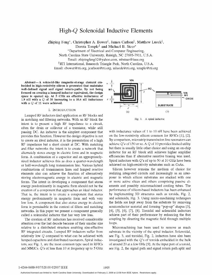
attention over the last decade because of their smaller sizerelative to a distributed structure enabling size-effectiveRF integrated circuits. Lumped RF inductors suffer fromrelatively low Q compared to what can be achieved withlumped capacitors and distributed resonators. Spiral induc-tors, see Fig. 1, are the most common type used in RFICsand MMICs. Q's of less than 10 at frequency up to 5 GHz
VIA
VIAmlOXIDE
a SUBSTRATEd
(a) (b)
Fig. 1. A spiral inductor.
with inductance values of 1 to 10 nH have been achievedon the low-resistivity silicon common for RFICs [1], [2].By comparison, microstrip transmission line resonators canachieve Q's of 150 or so. A Q of 10 provides limited utilitybut there is usually little other choice and using an on-chipinductor for an RF block still achieves higher amplifierefficiencies than if alternative resistive biasing was used.Spiral inductors with Q's of up to 50 at 10 GHz have beenachieved on high-resistivity substrates such as GaAs.
Silicon however remains the medium of choice forrealizing integrated circuits and increasingly as an inter-poser in which silicon substrates are stacked with oneor more active slices and others comprising passive el-ements and possibly micromachined cooling tubes. Theperformance of silicon-based inductors has been enhancedby implementing 3D structures such as toroids, Fig. 2,and solenoids, Fig. 3. Using micro-machining techniquesthe fields are kept away from the substrate by removingsemiconductor material and forming "pop-up" shapes [3],[4], [5], [6], [7], [8]. Toroidal and solenoidal inductorsachieve part of their performance by enhancing the fluxcoupling by directing the magnetic field through multipleloops.
Micromachining has been used to remove as muchsubstrate in the vicinity of the spiral inductor. Solenoidal,see Fig. 3, and toroidal, Fig. 2, inductors have also beeninvestigated with the Q's of toroids embedded in the bulkof around 20 at a few GHz [9]. At the input port of a toroid,see Fig. 2, the signal path and signal return path split and
1-4244-0688-9/07/$20.00 C 2007 IEEE 1 905Authorized licensed use limited to: North Carolina State University. Downloaded on February 2, 2009 at 13:58 from IEEE Xplore. Restrictions apply.

INPUT PORT
Fig. 2. A toroidal inductor.
TABLE I
MODEL PARAMETERS FOR THE SOLENOIDAL INDUCTORS SHOWN IN
FIG. 3. THE TRANSMISSION LINES HAVE Z0 = 110 Q, AND f = 10°AT 10 GHz.
Turns Figure LL RL CL CS CC(nH) (Q) (fF) (fF) (fF)
1 3(a) 0.35 0.4 40 35 652 3(b) 1.2 0.4 45 45 653 3(c) 1.9 0.5 55 55 854 3(d) 2.8 0.6 60 55 1005 3(e) 3.8 0.7 60 58 110
follow different directions around the toroid. In practicethis means that toroids are sensitive to nearby conductors.As such care must be used in using these devices.The main intent of the work being pursued here is
producing a layer of passives for a silicon-based 3D stack-up. As such pop-up structures are not suitable. Howeverwith an embedded passive layer without active devices a
high-resistivity substrate can be used without limitation.Fortuitously, high-resistivity silicon substrates (10 kQ-cm)are becoming increasingly available and affordable.
II. INDUCTIVE ELEMENT DESIGN
The direction taken in this work was to develop a
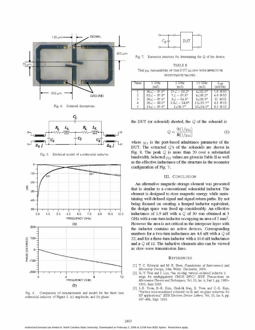
magnetic energy storage element with well-defined signalreturn path as well as being embedded in the bulk. Thestructure developed is shown in Fig. 3 for solenoidalstructures with one to five turns. The dimensions of theone-turn solenoid are shown in Fig. 4. The structure iseffective at storing magnetic energy. The model of thesolenoid is shown in Fig. 5 and the fitted parameters are
given in Table I. An example of the fit obtained is shownin Fig. 6 for the 3-turn inductor.
It is not straightforward to determine the Q of thedevice presented here as magnetic energy is not storedin a single lumped component. Here the Q is calculatedwith the solenoid connected in a resonator with an idealshunt capacitor CR. In this configuration with Port 2 of
(d)
(e)
Fig. 3. Solenoidal inductor.
1906
(a)
(b)
(c)
Authorized licensed use limited to: North Carolina State University. Downloaded on February 2, 2009 at 13:58 from IEEE Xplore. Restrictions apply.
125 pm - SIGNAL01/, CR1 DUT
400 pm
75 t rr
:+- 900 pmGROUND
Fig. 4. Solenoid dimensions.
Fig. 7. Resonator structure for determining the Q of the device.
TABLE II
THE Y1I PARAMETER OF THE DUT ALONG WITH EFFECTIVE
INDUCTANCE VALUES.
the DUT (or solenoid) shorted, the Q of the solenoid is
U0 'Sz _o%V\ ~
zo,
Fig. 5. Electrical model of a solenoidal inductor.
-10
-20a
-30
-40
S21
-50
0.0 1.5 3.0 4.5 6.0 7.5FREQUENCY (GHz)
(a)200-
100-
0-
-100-
-200- l l l l l l0 4 8
FREQUENCY (GHz)
(b)
Fig. 6. Comparison of measurements and model for the three turnsolenoidal inductor of Figure 3. (a) amplitude; and (b) phase.
Q_ (/Yll)R(l/Yll) (1)
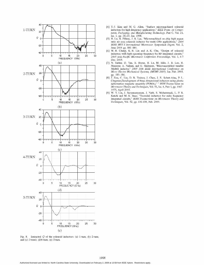
where Yll is the port-based admittance parameter of theDUT. The extracted Q's of the solenoids are shown inFig. 8. The peak Q is more than 20 over a substantialbandwidth. Selected Yll values are given in Table II as wellas the effective inductance of the structure in the resonatorconfiguration of Fig. 7.
III. CONCLUSION
An alternative magnetic-storage element was presentedthat is similar to a conventional solenoidal inductor. Theelement is designed to store magnetic energy while main-taining well-defined signal and signal return-paths. By notbeing focused on creating a lumped inductor equivalent,the design space was freed up considerably. An effective
9.0 10.5 12.0 inductance of 1.9 nH with a Q of 30 was obtained at 5GHz with a one-turn inductor occupying an area of 2 mm2.However the area is not critical as the interposer layer withthe inductor contains no active devices. Correspondingnumbers for a two-turn inductance are 4.6 nH with a Q of22; and for a three-turn inductor with a 10.6 nH inductanceand a Q of 11. The inductive elements also can be viewedas slow-wave transmission lines.
REFERENCES
[1] T. C. Edwards and M. B. Steer, Foundations of Interconnect andMicrostrip Design, John Wiley: Chichester, 2000.
[2] H.-Y. Tsui and J. Lau, "An on-chip vertical solenoid inductor design for multigigahertz CMOS RFIC," IEEE Transactions on
Microwave Theory and Techniques, Vol. 53, Iss. 6, Part 1, pp. 1883-1890, June 2005.
[3] J.-B. Yoon, B.-K. Kim, Chul-Hi Han, E. Yoon and C.-K. Kim,"Surface micromachined solenoid on-Si and on-glass inductors forRF applications," IEEE Electron Device Letters, Vol. 20, Iss. 9, pp.
487-489, Sept. 1999.
1907
[Turns T 1 GHz 5 GHz [10 GHz [ Leffl____ (imS) (mS) [ (mS) (nH/Hz)
1 95/- 87.60 17/ -88.20 4/82.00 1.9 @5G2 53/- 87.80 7/ -87.5 4/86.20 4.6 @5G3 35- 87.90 3/ -84.8 8/88.00 11 @5G4 25- 88.00 2.6Z -34.50 12z87.70 6.3 @1G5 19/ -87.90 1/81.70 20/84.00 8.3 @1G
uJLLILLI
(9
LLI
LIUJuJnO
1.2
Authorized licensed use limited to: North Carolina State University. Downloaded on February 2, 2009 at 13:58 from IEEE Xplore. Restrictions apply.
FREQUENCY (GHz)
40-
20-
0-
-20-
-40- - IIIT
0 5 10 15 20 25 3(FREQUENCY (GHz)
40- . -. . . .-i--r
0 5 10 15 20FREQUENCY (GHz)
(c)
40
[4] Y-J. Kim and M. G. Allen, "Surface micromachined solenoidinductors for high frequency applications," IEEE Trans. on Compo-nents, Packaging, and Manufacturing Technology, Part C, Vol. 21,Iss. 1, pp. 26-33, Jan. 1998.
[5] H. Lu, B. Pillans, J.-B. Lee, "Micromachined on-chip high-aspectratio air core solenoid inductor for multi-GHz applications," 2004IEEE MIT-S International Microwave Symposium Digest, Vol. 2,June 2004 pp. 881-884.
[6] M.-H. Chang; K.-H. Lin and A.-K. Chu, "Design of solenoidinductors with high operating frequency for RF integrated circuits,"2005 Asia-Pacific Microwave Conference Proceedings, Vol. 1, 4-7Dec. 2005.
[7] N. Sarkar, D. Yan, E. Horne, H. Lu, M. Ellis, J. B. Lee, R.Mansour, A. Nallani, and G. Skidmore, "Microassembled tunableMEMS inductor," 2005 18th IEEE International Conference onMicro Electro Mechanical Systems, (MEMS 2005), Jan.-Feb. 2005,pp. 183-186.
[8] J. Zou, C. Liu; D. R. Trainor, J. Chen, J. E. Schutt-Aine, P. L.Chapman,Development of three-dimensional inductors using plasticdeformation magnetic assembly (PDMA)," " IEEE Transactions onMicrowave Theory and Techniques, Vol. 51, Iss. 4, Part 1, pp. 1067-1075, April 2003.
[9] W. Y Liu, J. Suryanarayanan, J. Nath, S. Mohammadi, L. P. B.Katehi and M. B. Steer, "Torroidal inductors for radio frequencyintegrated circuits," IEEE Transactions on Microwave Theory andTechniques, Vol. 52, pp. 646-654, Feb. 2004.
Jo
25 30
(d)
20
0
20
-40 I|0 5 10 15 20
FREQUENCY(GHz25 30
(e)
Fig. 8. Extracted Q of the solenoid inductors: (a) 1-turn; (b) 2-turn;and (c) 3-turn); (d)4-turn; (e) 5-turn.
1908
1-TURN
2-TURN
3-TURN
4-TURN
5-TURN
Q
,0
Q
Q-
Authorized licensed use limited to: North Carolina State University. Downloaded on February 2, 2009 at 13:58 from IEEE Xplore. Restrictions apply.


