Engineering & Geosciences
14425 South Center Point Way Bluffdale, Utah 84065 Phone (801) 501-0583 | Fax (801) 501-0584
Geotechnical Investigation for the Pavement Design
1100 West and Highway 91 Intersection Project Brigham City, Utah
GeoStrata Job No. 320-010
January 4, 2013
Prepared for:
Horrocks Engineers Inc. 2162 West Grove Parkway, Suite 400
Pleasant Grove, Utah 84062
Attention: Mr. Doug Graham, P.E.


Copyright 2012 GeoStrata i R320-010
TABLE OF CONTENTS
1.0 EXECUTIVE SUMMARY ..................................................................................................................... 1
2.0 INTRODUCTION ................................................................................................................................... 2
2.1 PURPOSE AND SCOPE OF WORK ............................................................................................... 2
2.2 PROJECT DESCRIPTION ............................................................................................................... 2
3.0 METHOD OF STUDY ............................................................................................................................ 3
3.1 FIELD INVESTIGATION ................................................................................................................ 3
3.2 LABORATORY TESTING .............................................................................................................. 3
3.3 ENGINEERING ANALYSIS ........................................................................................................... 4
4.0 GENERALIZED SITE CONDITIONS ................................................................................................. 5
4.1 SURFACE CONDITIONS ............................................................................................................... 5
4.2 SUBSURFACE CONDITIONS ........................................................................................................ 5
4.2.1 Soils ......................................................................................................................................... 5
4.2.2 Groundwater ............................................................................................................................ 6
5.0 GEOLOGIC CONDITIONS .................................................................................................................. 7
5.1 GEOLOGIC SETTING ..................................................................................................................... 7
5.2 SEISMICITY AND FAULTING ...................................................................................................... 7
5.3 OTHER GEOLOGIC HAZARDS .................................................................................................... 8
5.3.1 Liquefaction ............................................................................................................................. 9
5.3.2 Lake Flooding .......................................................................................................................... 9
5.3.3 Seiches ................................................................................................................................... 10
5.3.4 Shallow Groundwater ............................................................................................................ 10
6.0 ENGINEERING ANALYSIS AND RECOMMENDATIONS .......................................................... 11
6.1 GENERAL CONCLUSIONS ......................................................................................................... 11
6.2 EARTHWORK ............................................................................................................................... 11
6.2.1 General Site Preparation and Grading ................................................................................. 11
6.2.2 Excavations for Conventional Pavement Reconstruction ...................................................... 12
6.2.3 Excavation Observation and Plan Review ............................................................................. 12
6.2.4 Temporary Excavation Stability ............................................................................................ 12
6.2.5 Borrow, Granular Borrow, Granular Backfill Borrow and Compaction .............................. 13
6.3 MOISTURE PROTECTION AND SURFACE DRAINAGE ........................................................ 14
6.4 FLEXIBLE PAVEMENT DESIGN ................................................................................................ 14
6.5 SOIL CORROSION AND REACTIVITY ..................................................................................... 15
Copyright 2012 GeoStrata ii R320-010
7.0 CLOSURE .............................................................................................................................................. 17
7.1 LIMITATIONS ............................................................................................................................... 17
7.2 ADDITIONAL SERVICES ............................................................................................................ 17
8.0 REFERENCES CITED ..................................................................................................................... 19
APPENDIX
Appendix A Plate A-1 Site Vicinity Map
Plate A-2 Exploration Location Map
Plate A-3 Surficial Geologic Map
Appendix B Plates B-1 to B-4 Boring Logs
Plate B-5 Key to Soil Symbols and Terms
Appendix C Plate C-1 Lab Summary Report
Plate C-2 Atterberg Limits
Plate C-3 Grain Size Distribution
Plates C-4 to C-5 Compaction and CBR Tests

Copyright 2012 GeoStrata 1 R320-010
1.0 EXECUTIVE SUMMARY
This report presents the results of a geotechnical investigation conducted for the proposed
construction of the intersection of 1100 West and Highway 91 in Brigham City, Utah. The
proposed improvements will include the construction of approximately 1,100 feet of new
roadway along the 1100 West alignment as well as approximately 1,800 feet of additional
turning lane area along Highway 91. The purposes of this investigation were to assess the nature
and engineering properties of the subsurface soils at the proposed site and to provide
recommendations for general site grading and the design and construction of the new roadways.
Based on the four borings drilled for this investigation, subgrade soils along the proposed 1100
West alignment generally consist of 0 to 6 inches of fill soils composed of Poorly Graded
GRAVEL (GP-GM) with silt and sand. Native soils were encountered under the fill soils, and
generally consisted of soft to medium stiff Sandy Lean CLAY (CL) and Lean CLAY (CL), as
well as loose Silty SAND (SM). The subgrade soils along the Highway 91 alignment generally
consist of 6 to 10 feet of fill soils composed of Poorly Graded GRAVEL (GP-GM) with silt and
sand as well as Poorly Graded SAND (SP) with gravel. Native soils underling the fill soils
consist of Lean CLAY (CL), Sandy Lean CLAY (CL), Sandy SILT (ML) and Silty SAND (SM).
Groundwater was encountered in each of the boreholes at depths ranging from 1 to 13 feet below
the existing site grade. Groundwater conditions can be expected to rise several feet depending on
the time of year. Based on the subsurface conditions encountered at the site, it is our opinion that
the subject site is suitable for the proposed construction provided that the recommendations
contained in this report are complied with. The following recommendations and design
parameters are discussed within this report.
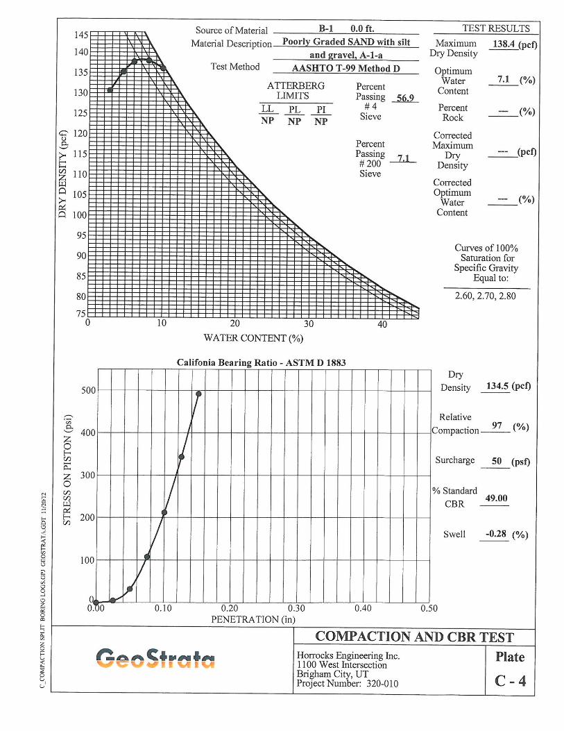
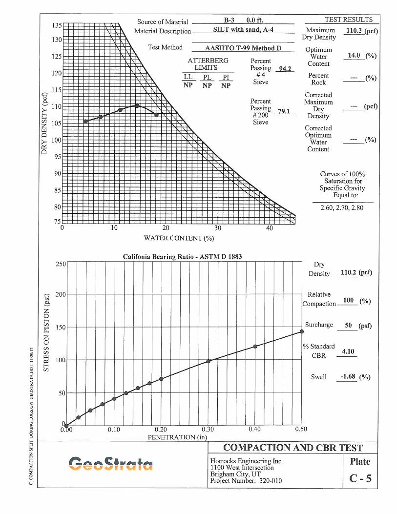
A California bearing ratio (CBR) of 4.1 was determined for the subgrade soil encountered along
the roadway alignments, indicating that the native soils can be expected to provide poor
pavement support. Asphalt, untreated base course, and granular borrow thickness
recommendations are presented in Section 6.4 of this report.
NOTICE: The scope of services provided within this report is limited to the assessment of the existing subsurface conditions for the proposed roadway improvement. In the event that existing conditions change, results and recommendations contained in this report may need to be modified. This executive summary is not intended to replace the report of which it is part and should not be used separately from the report. The executive summary is provided solely for purposes of overview. The executive summary omits a number of details, any one of which could be crucial to the proper application of this report.

Copyright 2012 GeoStrata 2 R320-010
2.0 INTRODUCTION
2.1 PURPOSE AND SCOPE OF WORK
This report presents the results of a geotechnical investigation conducted for the proposed
intersection to be constructed at 1100 West and Highway 91 in Brigham City, Utah. The
purposes of this investigation were to assess the nature and engineering properties of the
subsurface soils at the proposed site and to provide recommendations for general site grading and
the design and construction of the new roadway and other associated improvements.
The scope of work completed for this study included a site reconnaissance, subsurface
exploration, soil sampling, laboratory testing, engineering analyses, and preparation of this
report. Our services were performed in accordance with our proposal and signed authorization,
dated June 21, 2012 .The recommendations contained in this report are subject to the limitations
presented in the "Limitations" section of this report (Section 7.1).
2.2 PROJECT DESCRIPTION
The project as planned will consist of the reconstruction of the intersection of 1100 West and
1100 South (Highway 91) in Brigham City, Utah. We understand that this reconstruction will
involve the construction of approximately 1,100 feet of roadway along 1100 West as well as
adding approximately 1,800 feet of additional lane area along either direction of Highway 91.
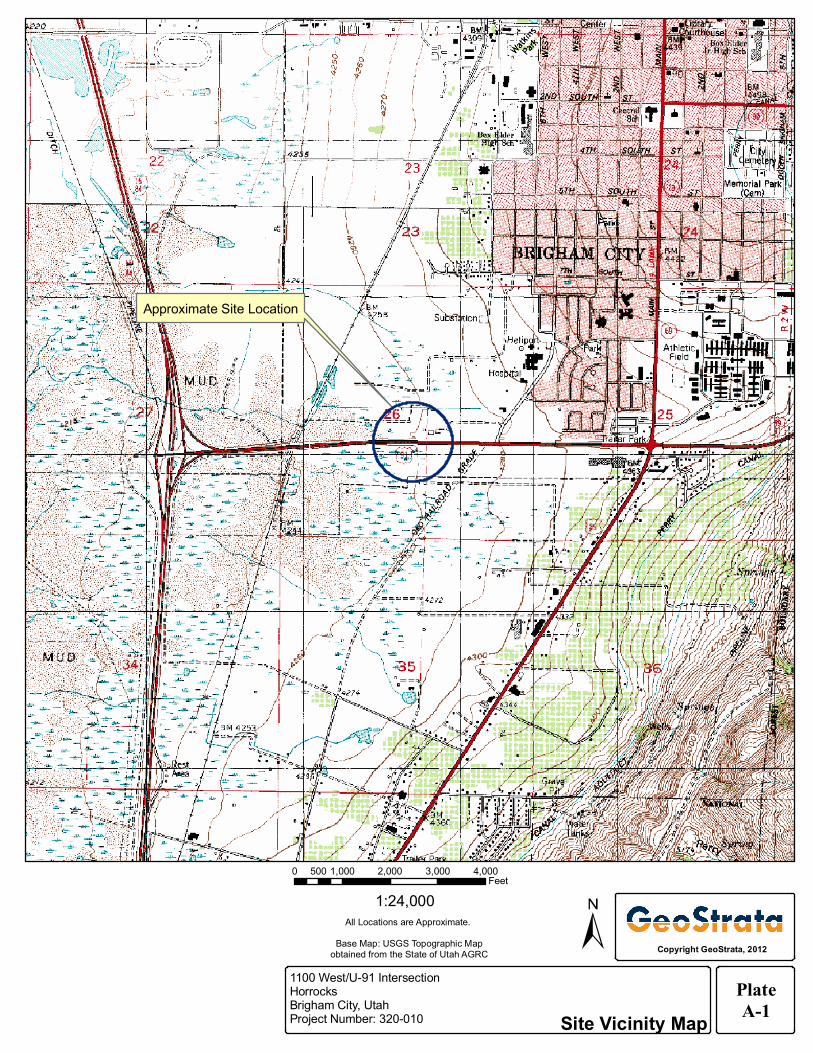
The location of the project site is shown on the Site Vicinity Map, Plate A-1. It is our
understanding that the new portions of both roadways constructed approximately 0 to 10 feet
above native grades in order to tie in with the existing roadways. Improvements may also include
sidewalk and curb and gutter additions.
Copyright 2012 GeoStrata 3 R320-010
3.0 METHOD OF STUDY
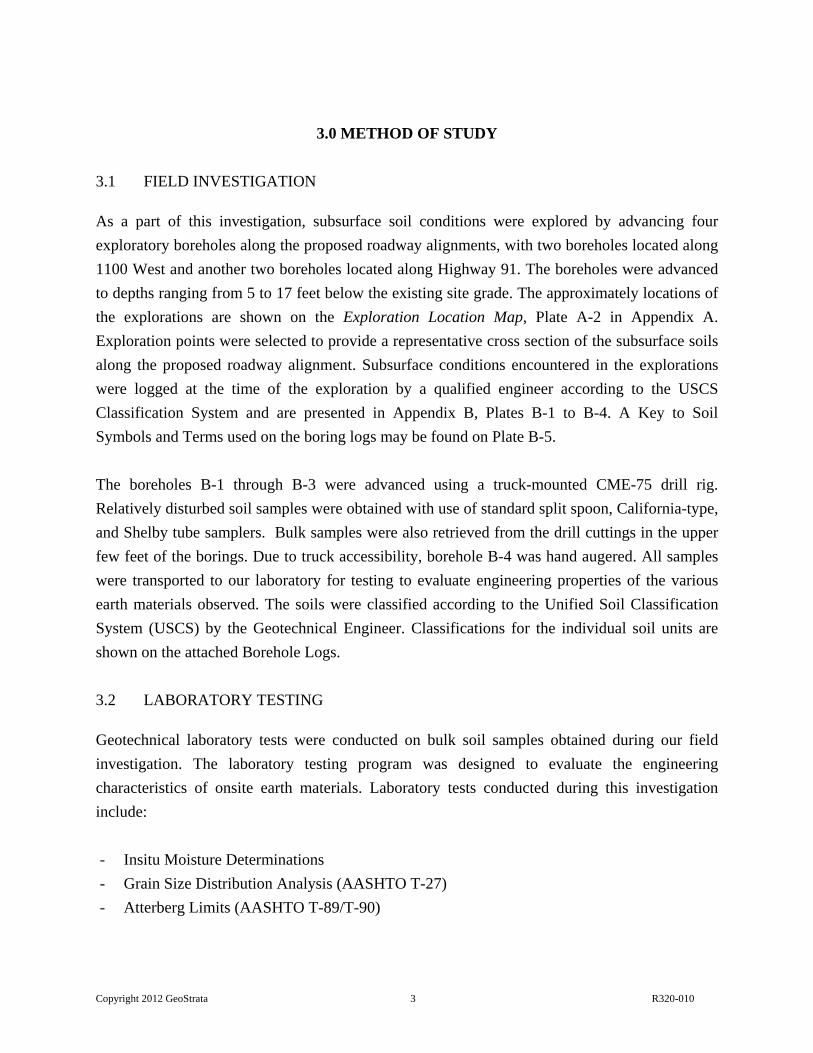
3.1 FIELD INVESTIGATION
As a part of this investigation, subsurface soil conditions were explored by advancing four
exploratory boreholes along the proposed roadway alignments, with two boreholes located along
1100 West and another two boreholes located along Highway 91. The boreholes were advanced
to depths ranging from 5 to 17 feet below the existing site grade. The approximately locations of
the explorations are shown on the Exploration Location Map, Plate A-2 in Appendix A.
Exploration points were selected to provide a representative cross section of the subsurface soils
along the proposed roadway alignment. Subsurface conditions encountered in the explorations
were logged at the time of the exploration by a qualified engineer according to the USCS
Classification System and are presented in Appendix B, Plates B-1 to B-4. A Key to Soil
Symbols and Terms used on the boring logs may be found on Plate B-5.
The boreholes B-1 through B-3 were advanced using a truck-mounted CME-75 drill rig.
Relatively disturbed soil samples were obtained with use of standard split spoon, California-type,
and Shelby tube samplers. Bulk samples were also retrieved from the drill cuttings in the upper
few feet of the borings. Due to truck accessibility, borehole B-4 was hand augered. All samples
were transported to our laboratory for testing to evaluate engineering properties of the various
earth materials observed. The soils were classified according to the Unified Soil Classification
System (USCS) by the Geotechnical Engineer. Classifications for the individual soil units are
shown on the attached Borehole Logs.
3.2 LABORATORY TESTING
Geotechnical laboratory tests were conducted on bulk soil samples obtained during our field
investigation. The laboratory testing program was designed to evaluate the engineering
characteristics of onsite earth materials. Laboratory tests conducted during this investigation
include:
- Insitu Moisture Determinations
- Grain Size Distribution Analysis (AASHTO T-27)
- Atterberg Limits (AASHTO T-89/T-90)
Copyright 2012 GeoStrata 4 R320-010
- Maximum Dry Density and Optimum Moisture Content (AASHTO T-99)
- California Bearing Ratio (AASHTO T-193)
The results of laboratory tests are presented on the Boring Logs in Appendix B (Plates B-1 to B-
4) as well as the Laboratory Summary Table and the test results plates presented in Appendix C
(Plates C-1 to C-5).
3.3 ENGINEERING ANALYSIS
Engineering analyses were performed using soil data obtained from the laboratory test results
and empirical correlations from material density, depositional characteristics and classification.
Appropriate factors of safety were applied to the results consistent with industry standards and
the accepted standard of care.

Copyright 2012 GeoStrata 5 R320-010
4.0 GENERALIZED SITE CONDITIONS
4.1 SURFACE CONDITIONS
The proposed 1100 West roadway alignment is oriented approximately north-south, while
Highway 91 is oriented approximately east-west. Both alignments are roughly level. Currently,
1100 West terminates approximately 350 feet north of Highway 91. The proposed alignment of
1100 West along both sides of Highway 91 is currently occupied by undeveloped, moderately
vegetated, agricultural lots. The proposed alignment is bordered by commercial property to the
east and undeveloped properties to the north, south, and west.
4.2 SUBSURFACE CONDITIONS
As previously mentioned, the subsurface soil conditions were explored along the proposed
roadway alignments by advancing four exploratory boreholes to depths ranging from 5 to 17 feet
below the existing site grade. The soils encountered in the borings were visually classified and
logged during our field investigation and are included on the boring logs in Appendix B (Plates
B-1 to B-4). The subsurface conditions encountered during our investigation are discussed
below.
4.2.1 Soils
Based on our observations and geologic literature review, the subject alignment is overlain by 0
to 10 feet of fill soils. Underlying the fill we encountered upper Pleistocene-aged lacustrine
deposits which extended to the full depth of our investigation. The geologic units encountered
are discussed below;
Fill: Generally consists of medium dense, moist to very moist, brown to dark brown Poorly
Graded GRAVEL (GP-GM) with silt and sand as well as Poorly Graded SAND (SP) with gravel,
although occasional seams of clayey soil were observed throughout this material. Typically
gravel diameter ranged from approximately 1½ to 2 inches. Occasional clasts of concrete were
also observed. It is likely that the fill soils encountered in boreholes B-1 and B-2 within
Highway-91 right of way was placed and compacted in accordance with UDOT standards. Fill
soils were encountered in borehole B-3 is likely undocumented. Where encountered, the fill soils
ranged from 1 to 10 feet in thickness.
Copyright 2012 GeoStrata 6 R320-010
Upper-Pleistocene Lacustrine Deposits: The lacustrine deposits encountered at the site are
composed of Lean CLAY (CL), Sandy Lean CLAY (CL), Sandy SILT (ML), and Silty SAND
(SM). In general, these deposits were moist stiff to soft, moist to wet, and light brown to black in
color. The clay typically had low plasticity and the sand was typically fine-grained. Occasional
seams of orange iron staining as well as preserved organic material were observed throughout
this soil unit. These deposits persisted to the full depth of our investigation.
The stratification lines shown on the enclosed test pit logs represent the approximate boundary
between soil types. The actual in-situ transition may be gradual. Due to the nature and
depositional characteristics of the native soils, care should be taken in interpolating subsurface
conditions; soil types may vary between and/or beyond exploration locations.
4.2.2 Groundwater
Groundwater was encountered in each of the boreholes advanced as part of our investigation at
depths ranging from 1 to 13 feet below the existing site grade. Based on the groundwater
elevations encountered in the boreholes, it appears that groundwater is near the native ground
elevation. Seasonal fluctuations in precipitation, surface runoff from adjacent properties, or other
on or offsite sources may also increase moisture conditions at the site. Based on the season of our
investigation (winter), we anticipate groundwater to be near its seasonal average, however
groundwater conditions can be expected to rise several feet depending on the time of year.
Copyright 2012 GeoStrata 7 R320-010
5.0 GEOLOGIC CONDITIONS
5.1 GEOLOGIC SETTING
The subject site is located at an elevation of approximately 4,260 feet in Brigham City, Utah.
Brigham City is located in the northern portion of the Salt Lake Basin, which is a deep,
sediment-filled structural basin of Cenozoic age flanked by the Wasatch Range and Wellsville
Mountains to the east and the Promontory Mountains, the Spring Hills, and the West Hills to the
west (Hintze, 1980). The southern portion of the Salt Lake Basin is bordered on the west by the
east shore of the Great Salt Lake. The Wasatch Range is the easternmost expression of
pronounced Basin and Range extension in north-central Utah.
The near-surface geology of the Salt Lake basin is dominated by sediments, which were
deposited within the last 30,000 years by Lake Bonneville (Scott and others, 1983; Hintze,
1993). As the lake receded, streams began to incise large deltas that had formed at the mouths of
major canyons along the Wasatch Range, and the eroded material was deposited in shallow lakes
and marshes in the basin and in a series of recessional deltas and alluvial fans. Sediments toward
the center of the valley are predominately deep-water deposits of clay, silt and fine sand.
However, these deep-water deposits are in places covered by a thin post-Bonneville alluvial
cover. Surface sediments at the site are mapped as upper Pleistocene-aged lacustrine silt and clay
related to the Provo and Bonneville shorelines (Personius, 1992).
5.2 SEISMICITY AND FAULTING
The site lies on the east side of the north-south trending belt of seismicity known as the
Intermountain Seismic Belt (ISB) (Hecker, 1993). The ISB extends from northwestern Montana
through southwestern Utah. An active fault is defined as a fault that has had activity within the
Holocene (<11ka). No active faults are reported to run through or immediately adjacent to the
site (Black and others, 2003). The site is located approximately ½ mile southwest of the Brigham
City segment of the Wasatch fault zone. The Brigham City segment is reported to be active and
thought to generate earthquakes of approximate magnitude 7.0 to 7.5 every 1300 ±200 years
(Black and others, 2004). The site is also located approximately 30 miles northeast of the East
Great Salt Lake fault zone (Hecker, 1993). Evidence suggests that this fault zone has been active
during the Holocene (0 to 10,000 yrs) and has segment lengths comparable to that of the
Wasatch fault zone, indicating that it is capable of producing earthquakes of a comparable
Copyright 2012 GeoStrata 8 R320-010
magnitude (7.5 Ms). Analyses of the ground shaking hazard along the Wasatch Front suggest
that the Wasatch Fault Zone is the single greatest contributor to the seismic hazard in Wasatch
front region.
Seismic hazard maps depicting probabilistic ground motions and spectral response have been
developed for the United States by the U.S. Geological Survey as part of NEHRP/NSHMP
(Frankel et al, 1996). These maps have been incorporated into both NEHRP Recommended
Provisions for Seismic Regulations for New Buildings and Other Structures (FEMA, 1997) and
the International Building Code (IBC) (International Code Council, 2006). Spectral responses
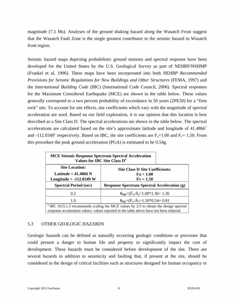
for the Maximum Considered Earthquake (MCE) are shown in the table below. These values
generally correspond to a two percent probability of exceedance in 50 years (2PE50) for a “firm
rock” site. To account for site effects, site coefficients which vary with the magnitude of spectral
acceleration are used. Based on our field exploration, it is our opinion that this location is best
described as a Site Class D. The spectral accelerations are shown in the table below. The spectral
accelerations are calculated based on the site’s approximate latitude and longitude of 41.4866˚
and -112.0349˚ respectively. Based on IBC, the site coefficients are Fa=1.00 and Fv= 1.50. From
this procedure the peak ground acceleration (PGA) is estimated to be 0.54g.
MCE Seismic Response Spectrum Spectral Acceleration Values for IBC Site Class Da
Site Location:
Latitude = 41.4866 N Longitude = -112.0349 W
Site Class D Site Coefficients: Fa = 1.00 Fv = 1.50
Spectral Period (sec) Response Spectrum Spectral Acceleration (g)
0.2 SMS=(Fa*Ss=1.00*1.36= 1.36
1.0 SM1=(Fv*S1=1.50*0.54= 0.81 a IBC 1615.1.3 recommends scaling the MCE values by 2/3 to obtain the design spectral response acceleration values; values reported in the table above have not been reduced.
5.3 OTHER GEOLOGIC HAZARDS
Geologic hazards can be defined as naturally occurring geologic conditions or processes that
could present a danger to human life and property or significantly impact the cost of
development. These hazards must be considered before development of the site. There are
several hazards in addition to seismicity and faulting that, if present at the site, should be
considered in the design of critical facilities such as structures designed for human occupancy or

Copyright 2012 GeoStrata 9 R320-010
critical facilities that support emergency response or life-sustaining activity. The hazards
considered for this site include liquefaction, lake flooding, seiche, and shallow groundwater.
5.3.1 Liquefaction
Certain areas within the Intermountain region possess a potential for liquefaction during seismic
events. Liquefaction is a phenomenon whereby loose, saturated, granular soil deposits lose a
significant portion of their shear strength due to excess pore water pressure buildup resulting
from dynamic loading, such as that caused by an earthquake. Among other effects, liquefaction
can result in densification of such deposits causing settlements of overlying layers after an
earthquake as excess pore water pressures are dissipated. The primary factors affecting
liquefaction potential of a soil deposit are: (1) level and duration of seismic ground motions; (2)
soil type and consistency; and (3) depth to groundwater.
Referring to the “Liquefaction Potential Brigham City,” published by the Utah Emergency
Operations Plan, the subject site is located within an area currently designated as "high" for
liquefaction potential. Groundwater was encountered during our investigations at depths ranging
from 1 to 13 feet below the existing site grade. Due to the presence of this shallow groundwater,
there is a high potential that the site will be impacted by liquefaction. A liquefaction analysis was
beyond the scope of this investigation. However, if the client wishes to have a greater
understanding of the liquefaction potential for soils at depth, a liquefaction analysis should be
completed.
5.3.2 Lake Flooding
A flood is the stage or height of water above some given datum, such as a commonly occupied
lake shoreline. Floods are recurrent natural events which become a hazard to residents of a flood
plain or shoreline whenever water rises to the extent that life and property are threatened.
Although fluctuating water levels are a problem in lakes, they are especially acute in lakes
which, like the Great Salt Lake, have no outlet. Natural factors causing fluctuations include
precipitation, evaporation, runoff, groundwater, ice, aquatic growth, and wind.
Using available historical and scientific data on the Great Salt Lake, lake experts have
recommended that properties located at elevations lower than 4,217 feet be reserved as
“Beneficial Development Areas”. Within these areas, it is recommended that development take
place in a manner that will encourage the maximum use of the land for the people of Utah while

Copyright 2012 GeoStrata 10 R320-010
avoiding unnecessary disaster losses. As mentioned previously, the subject site is located at an
elevation of 4,260 feet. As such, it is considered very unlikely that the site will be impacted by
lake flooding from the Great Salt Lake.
5.3.3 Seiches
Oscillations in the surface of a landlocked body of water can produce unusually large waves, or
sieches. Seiches may be generated by wind, landslides, and/or earthquake effects such as ground
shaking or surface fault rupture. The magnitude of the seiches caused by landslides or surface
fault rupture depends on the amount of water and ground displacement, whereas the magnitude
of the seiches caused by wind and ground shaking is determined by the degree or resonance
between the water body and periodic driving force.
Studies of wind seiches in the Great Salt Lake concluded that the maximum wave amplitude is
expected to be about 2 feet; no systematic or theoretical studies of landslide or earthquake-
induced seiches have been made. However, seiches more than 12 feet in height were reported on
the lake during the 1909 Hansel Valley earthquake (magnitude 6). The elevation of the surface of
the Great Salt Lake as measured in October of 2012 was approximately 4,201 feet, whereas the
site is located at an elevation of approximately 4,260 feet. As such, it is considered very unlikely
that the site will be impacted by seiches created during a seismic event.
5.3.4 Shallow Groundwater
Shallow groundwater flooding is a hazard that can cause the flooding of excavated areas where
the depth of excavation exceeds the depth of the local water table. Shallow groundwater can lead
to increased construction costs and delays, as well as potentially dangerous conditions in
excavated trenches. Shallow groundwater flooding should be considered when designing
habitable structures that require excavation that may exceed the depth to the shallow
groundwater.
During our subsurface investigation, shallow groundwater was observed to vary from 1 to 14 feet
below the existing site grade. This was largely due to the presence of undocumented fill soils at
various portions of the site. It should be anticipated that the groundwater can rise several feet
during wet cycles and could impact site development. The contractor should anticipate
dewatering trenches and excavations deeper than 1 foot or possibly shallower during spring or
other times of the year when groundwater may fluctuate.

Copyright 2012 GeoStrata 11 R320-010
6.0 ENGINEERING ANALYSIS AND RECOMMENDATIONS
6.1 GENERAL CONCLUSIONS
Supporting data upon which the following recommendations are based have been presented in
the previous sections of this report. The recommendations presented herein are governed by the
physical properties of the soils encountered in the exploratory borings and our understanding of
the project as discussed in the PROJECT DESCRIPTION section of this report. If subsurface
conditions other than those described in this report are encountered in conjunction with
construction, and/or if design and layout changes are initiated, GeoStrata must be informed so
that our recommendations can be reviewed and revised as changes in conditions may require.
Changes in subsurface conditions that would necessitate further review include but are not
limited to: fluctuating groundwater or moisture content conditions, soils that are soft, collapsible,
expansive, or pumping, and soil types encountered that were not encountered during this
exploration or addressed in this report.
Based on the subsurface conditions encountered at the site, it is our opinion that the subject site
is suitable for the proposed development provided that the recommendations contained in this
report are incorporated into the design and construction of the project. The majority of the
subgrade soils encountered along the alignment consist of relatively soft, moist, fine-grained
material. Based on the results of our laboratory testing, these soils are anticipated to provide
relatively poor pavement support.
The following sub-sections present our recommendations for general site grading, fills, and
pavement sections.
6.2 EARTHWORK
Prior to the placement of any roadway improvements, general site grading is recommended to
provide proper drainage and moisture control on the subject property and to aid in preventing
differential movement as a result of variations in moisture conditions.
6.2.1 General Site Preparation and Grading
Below any proposed improvements, we recommend that all vegetation, heavily rooted topsoil,
debris, or otherwise unsuitable soils be removed. Where fill soils are exposed, the subgrade
should be scarified at least 12 inches and recompacted. All A-1 soils should be compacted to at

Copyright 2012 GeoStrata 12 R320-010
least 96% of the maximum dry density, as determined by AASHTO T180 (modified Proctor). All
other soils should be compacted to 96% of the maximum dry density as determined by AASHTO
T99 (standard proctor). The moisture content should be within 3% of optimum. Once the
scarification and recompaction is completed, the exposed soils should be proof-rolled with heavy
rubber-tired equipment such as a scraper or loader. Any soft/loose areas identified during proof-
rolling should be removed and replaced with structural fill as described in Section 6.2.5 of this
report or stabilized as recommended in Section 6.2.6. Following proof rolling and removal of
soft/loose areas, grading may be conducted to bring the site to grade.
6.2.2 Excavations for Conventional Pavement Reconstruction
Unsuitable soils that include soft, loose, or otherwise deleterious soils beneath pavements should
be over-excavated and replaced with structural fill. If over-excavation is required, the excavation
should extend a minimum of one foot laterally for every foot of depth of over-excavation.
Excavations should extend laterally at least two feet beyond pavements. If materials are
encountered that are not represented in the borehole logs or may present an engineering concern,
GeoStrata should be notified so observations and further recommendations as required can be
made.
Prior to placing engineered fill, any loose soils in the excavation bottom should be removed or
moisture conditioned as necessary at, or slightly above, optimum moisture content (OMC), and
compacted. All A-1 soils should be compacted to at least 96% of the maximum dry density, as
determined by AASHTO T180 (modified Proctor). All other soils should be compacted to 96%
of the maximum dry density as determined by AASHTO T99 (standard proctor). The moisture
content should be within 3% of optimum.
6.2.3 Excavation Observation and Plan Review
We recommend that a GeoStrata representative be on-site during all excavations to assess the
exposed subgrade soils for pavements. We further recommend that the Geotechnical Engineer be
allowed to review the grading plans when prepared to evaluate the compatibility of these
recommendations.
6.2.4 Temporary Excavation Stability
Based on Occupational Safety and Health Administration (OSHA) guidelines for excavation
safety, trenches with vertical walls up to 5 feet in depth may be occupied, however, the presence
Copyright 2012 GeoStrata 13 R320-010
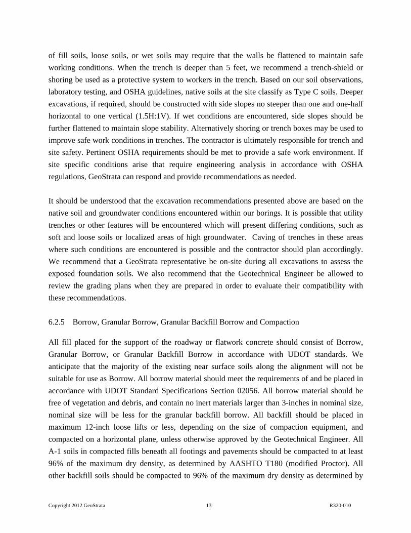
of fill soils, loose soils, or wet soils may require that the walls be flattened to maintain safe
working conditions. When the trench is deeper than 5 feet, we recommend a trench-shield or
shoring be used as a protective system to workers in the trench. Based on our soil observations,
laboratory testing, and OSHA guidelines, native soils at the site classify as Type C soils. Deeper
excavations, if required, should be constructed with side slopes no steeper than one and one-half
horizontal to one vertical (1.5H:1V). If wet conditions are encountered, side slopes should be
further flattened to maintain slope stability. Alternatively shoring or trench boxes may be used to
improve safe work conditions in trenches. The contractor is ultimately responsible for trench and
site safety. Pertinent OSHA requirements should be met to provide a safe work environment. If
site specific conditions arise that require engineering analysis in accordance with OSHA
regulations, GeoStrata can respond and provide recommendations as needed.
It should be understood that the excavation recommendations presented above are based on the
native soil and groundwater conditions encountered within our borings. It is possible that utility
trenches or other features will be encountered which will present differing conditions, such as
soft and loose soils or localized areas of high groundwater. Caving of trenches in these areas
where such conditions are encountered is possible and the contractor should plan accordingly.
We recommend that a GeoStrata representative be on-site during all excavations to assess the
exposed foundation soils. We also recommend that the Geotechnical Engineer be allowed to
review the grading plans when they are prepared in order to evaluate their compatibility with
these recommendations.
6.2.5 Borrow, Granular Borrow, Granular Backfill Borrow and Compaction
All fill placed for the support of the roadway or flatwork concrete should consist of Borrow,
Granular Borrow, or Granular Backfill Borrow in accordance with UDOT standards. We
anticipate that the majority of the existing near surface soils along the alignment will not be
suitable for use as Borrow. All borrow material should meet the requirements of and be placed in
accordance with UDOT Standard Specifications Section 02056. All borrow material should be
free of vegetation and debris, and contain no inert materials larger than 3-inches in nominal size,
nominal size will be less for the granular backfill borrow. All backfill should be placed in
maximum 12-inch loose lifts or less, depending on the size of compaction equipment, and
compacted on a horizontal plane, unless otherwise approved by the Geotechnical Engineer. All
A-1 soils in compacted fills beneath all footings and pavements should be compacted to at least
96% of the maximum dry density, as determined by AASHTO T180 (modified Proctor). All
other backfill soils should be compacted to 96% of the maximum dry density as determined by

Copyright 2012 GeoStrata 14 R320-010
AASHTO T99 (standard proctor). The moisture content should be within 3% of optimum for all
structural fill. Any imported fill materials should be approved prior to importing. Also, prior to
placing any fill, the excavations should be observed by the Geotechnical Engineer to confirm
that unsuitable materials have been removed. In addition, proper grading should precede
placement of fill, as described in the General Site Preparation and Grading subsection of this
report.
6.3 MOISTURE PROTECTION AND SURFACE DRAINAGE
Precautions should be taken during and after construction to minimize over-wetting of soils
beneath flatwork concrete and pavements. Moisture should not be allowed to infiltrate soils in
the vicinity of the proposed roadway alignment. Grading should be planned and executed to
provide positive surface drainage away from the alignment. We recommend using a minimum
surface slope of 2 percent for graded earth surfaces.
Over-wetting of soils prior to or during construction may result in softening and pumping of the
subgrade. This may result in equipment mobility problems and/or difficulty in achieving
compaction, and consequently, necessitate soil stabilization measures.
6.4 FLEXIBLE PAVEMENT DESIGN
As mentioned previously, 1 to 10 feet of fill soil was encountered within our borings. The fill
sections were thickest in boreholes B-1 and B-2, which were drilled within the existing Highway
91 pavement section. Boreholes B-3 and B-4 were advanced along the proposed 1100 West
alignment, where fill sections of 0 to 1 foot were encountered. The SPT blow counts indicate that
the fill soils are generally medium dense to dense; however, it should be understood that there
may be areas of fill with debris and/or low densities which could cause pavement settlement and
distress. Complete removal and replacement of the existing fill would be required to eliminate
this risk; however, removal and replacement of the entire existing fill could be cost prohibitive.
In general, the deeper the existing fill is removed and replaced the lower the risk of adverse
effects. As a minimum we recommend that where undocumented fill soils are exposed, the
subgrade should be scarified at least 12 inches and recompacted as recommended in Section
5.2.1; however, the risk associated with leaving the undocumented fill soils below the pavement
should be understood by the project owner prior to construction.
Copyright 2012 GeoStrata 15 R320-010
A bulk sample of the near surface soils was obtained from boring B-3 to assess the moisture-
density relationship and their capacity for pavement support. Laboratory testing yielded a CBR
value of 4.1% for the near surface soils. A second bulk sample of the fill soils was obtained from
boring B-1, and laboratory testing completed on this sample yielded a CBR value of 49%.
Traffic information for a section of Highway 91 that includes the subject interchange was
provided by the client. Based on the information provided, we estimate traffic for the Highway
91 turn lane and 1100 West will consist of 500 cars and 25 large trucks per day with 5 percent
growth per year. Using this traffic and a 20 year design lie, the total design equivalent axel loads
(ESAL’s is approximately 738,980 ESAL’s which was used for our assessment. For our
assessment a CBR value of 4.1% was utilized, and only a flexible pavement section was
considered. The software program WinPas was used in the design of the pavement section.
Based on the information presented above we recommend a minimum conventional pavement
section of 4½-inches of asphalt over 8-inches of untreated base and 13-inches of granular borrow
for both of the subject roadway alignments. Due to the shallow groundwater it is likely that soft
soils will be exposed following site grading and excavation recommend in Section 6.2.1 and
6.2.2. Where soft soils are encountered we recommend that that the granular borrow be increased
to 24 inches and that the granular borrow be underlain by a Tensar® TX-140, BX-1200, or
equivalent geotextile placed over native soils. This pavement section assumes that there is no
mixing over time between the granular borrow and the softer native layers below. In order to
prevent mixing of fines migration, and thereby prolong the life of the pavement section, we
recommend that the owner give consideration to placing a non-woven filter fabric between the
native soils and the granular borrow. We recommend that a Propex Geotex® NW-401, NW-406,
or a GeoStrata approve equivalent be used. It is anticipated that approximately 4 to 5 feet of
structural fill will be required in order to bring the proposed Highway 91 turn lanes up to design
grade. The recommended pavement sections should be incorporated into any planned fill
sections.
6.5 SOIL CORROSION AND REACTIVITY
Based on our experience in the area as well as with similar soils, the native silty soils are
anticipated to have a relatively low potential for sulfate attack on concrete, it is anticipated that
conventional Type I/II cement may be used for all concrete for this project.
Corrosion potential testing was not completed as part of this investigation; however, based on
our observations we anticipate that native soils will be corrosive to ferrous metal. Considerations

Copyright 2012 GeoStrata 16 R320-010
should be given to retaining the services of a qualified corrosion engineer to provide an
assessment of any metal that may be associated with the construction.

Copyright 2012 GeoStrata 17 R320-010
7.0 CLOSURE
7.1 LIMITATIONS
The recommendations contained in this report are based on limited field exploration, laboratory
testing, and our understanding of the proposed construction. The subsurface data used in the
preparation of this report were obtained from the explorations made for this investigation. It is
possible that variations in the soil and groundwater conditions could exist between and beyond
the points explored. The nature and extent of variations may not be evident until construction
occurs. If any conditions are encountered at this site that are different from those described in
this report, GeoStrata should be immediately notified so that we may make any necessary
revisions to recommendations contained in this report. In addition, if the scope of the proposed
construction changes from that described in this report, we should be notified.
This report was prepared in accordance with the generally accepted standard of practice at the
time the report was written. No warranty, expressed or implied, is made.
It is the Client's responsibility to see that all parties to the project including the Designer,
Contractor, Subcontractors, etc. are made aware of this report in its entirety. The use of
information contained in this report for bidding purposes should be done at the Contractor's
option and risk.
7.2 ADDITIONAL SERVICES
The recommendations made in this report are based on the assumption that an adequate program
of tests and observations will be made during the construction. GeoStrata staff should be on site
to observe compliance with these recommendations. These tests and observations should include,
but not necessarily be limited to, the following:
Observations and testing during site preparation, earthwork, and placement of granular
borrow, base course, and asphalt pavement.
Consultation as may be required during construction.
Asphalt compaction testing.

Copyright 2012 GeoStrata 18 R320-010
We also recommend that project plans and specifications be reviewed by GeoStrata to verify
compatibility with our conclusions and recommendations. Additional information concerning the
scope and cost of these services can be obtained from our office.
We appreciate the opportunity to be of service on this project. Should there be any questions
regarding the report or wish to discuss additional services, please do not hesitate to contact us at
(801) 501-0583.
Copyright 2012 GeoStrata 19 R320-010
8.0 REFERENCES CITED
Black, B.D., Hecker, S., Hylland, M.D., Christenson, G.E., and McDonald, G.N., 2003,
Quaternary Fault and Fold Database and Map of Utah: Utah Geological Survey Map 193DM. Federal Emergency Management Agency [FEMA], 1997, NEHRP Recommended Provisions for
Seismic Regulations for New Buildings and Other Structures, FEMA 302, Washington, D.C.
Frankel, A., Mueller, C., Barnard, T., Perkins, D., Leyendecker, E.V., Dickman, N., Hanson, S.,
and Hopper, M., 1996, National Seismic-hazard Maps: Documentation, U.S. Geological Survey Open-File Report 96-532, June.
Hecker, S., 1993, Quaternary Tectonics of Utah with Emphasis on Earthquake-Hazard
Characterization: Utah Geological Survey Bulletin 127, 157p. Hintze, L. F., 1980, Geologic Map of Utah: Utah Geological and Mineral Survey Map-A-1, scale
1:500,000. Hintze, L.F. 1993, Geologic History of Utah, Brigham Young University Studies, Special
Publication 7, 202p. International Building Code [IBC], 2006, International Code Council, Inc. Personius, S.F., 1992, Map of the Brigham City Segment and Adjacent Parts of the Weber
Segment of the Wasatch Fault Zone, Box Elder and Weber Counties, Utah, United Stated Geological Survey, Miscellaneous Investigations Series Map I-2107, Scale 1:50,000.
Scott, W.E., McCoy, W.D., Shorba, R.R., and Meyer, R., 1983, Reinterpretation of the exposed
record of the last two cycles of Lake Bonneville, western United States: Quaternary Research, v.20, p. 261-285.
0 1,000 2,000 3,000 4,000500Feet
1:24,000
Site Vicinity MapPlateA-1
Copyright GeoStrata, 2012
All Locations are Approximate. Base Map: USGS Topographic Map
obtained from the State of Utah AGRC
1100 West/U-91 IntersectionHorrocksBrigham City, UtahProject Number: 320-010
Approximate Site Location

0 100 200 300 40050Feet
1:3,000
Exploration Location MapPlateA-2
Copyright GeoStrata, 2012
All Locations are Approximate. Base Map: 2009 HRO 1 Foot Orthophotography
obtained from the State of Utah AGRC
1100 West/U-91IntersectionHorrocksBrigham City, UtahProject Number: 320-010
LegendBoring
B-1
B-3
B-2
B-4

0 1,100 2,200 3,300 4,400550Feet
1:24,000
Surficial Geologic MapPlateA-3
Copyright GeoStrata, 2012
All Locations are Approximate. Base Map: USGS Topographic Map
obtained from the State of Utah AGRC
1100 West/U-91 IntersectionHorrocksBrigham City, UtahProject Number: 320-010
Approximate Site Location
LegendContactFault, normal, approximately locatedFault, normal, well locatedWater BoundaryQa - surficial alluvium and colluviumQl - surficial Lake Bonneville depositsQm - surficial marsh depositsPCs - sedimentary and metasedimentary Fmswater
PlasticLimit
Dry
Den
sity
(pcf
)
Per
cen
t m
inu
s 2
00
N*
Mo
istu
re C
on
ten
t %
SPT BLOW COUNT
Project Number 320-010
Pla
stic
ity
In
dex
NE
W_L
OG
OF
BO
RIN
G (
A)
- IN
PR
OG
RE
SS
B
OR
ING
LO
GS
.GP
J G
EO
ST
RA
TA
.GD
T
12/1
7/1
2
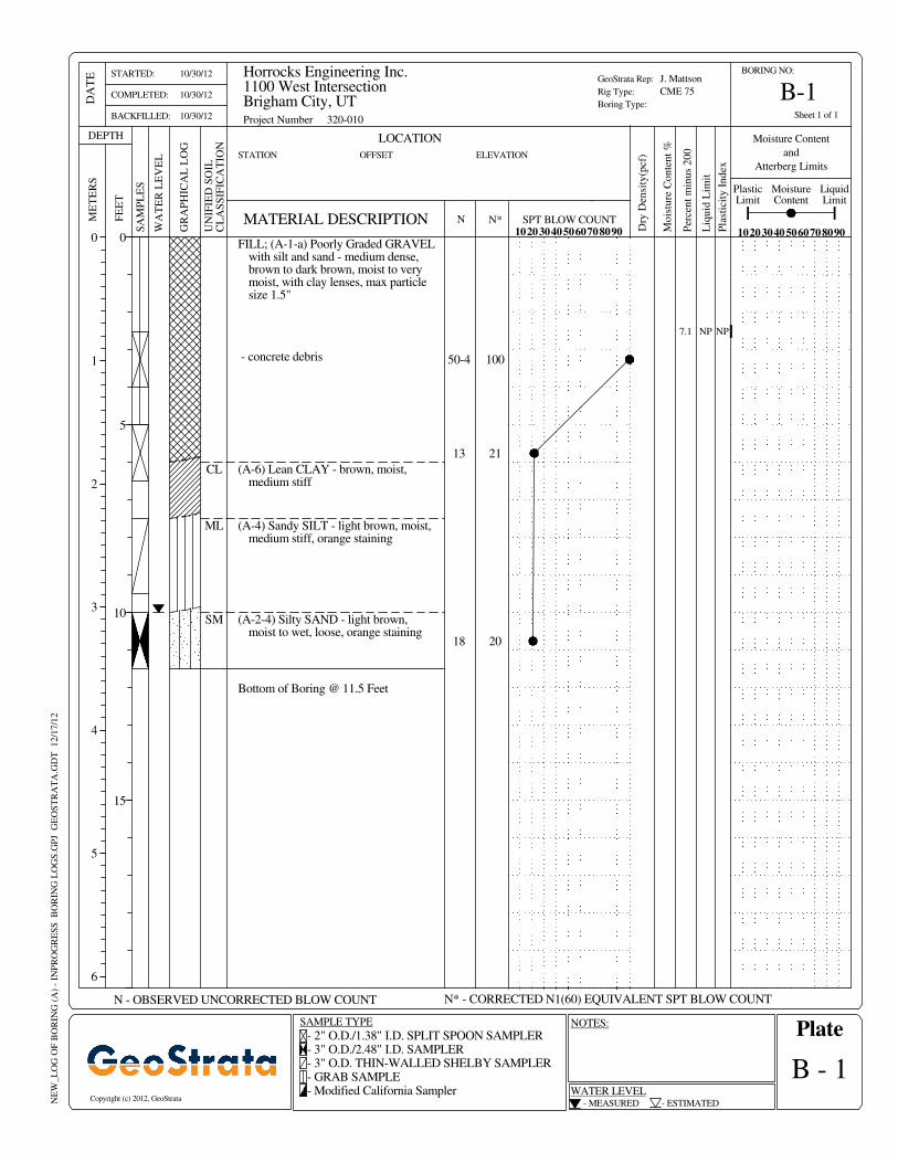
FILL; (A-1-a) Poorly Graded GRAVELwith silt and sand - medium dense,brown to dark brown, moist to verymoist, with clay lenses, max particlesize 1.5"
WA
TE
R L
EV
EL
NOTES:
MATERIAL DESCRIPTION
N* - CORRECTED N1(60) EQUIVALENT SPT BLOW COUNT
- 2" O.D./1.38" I.D. SPLIT SPOON SAMPLER- 3" O.D./2.48" I.D. SAMPLER- 3" O.D. THIN-WALLED SHELBY SAMPLER- GRAB SAMPLE- Modified California Sampler
- MEASURED
WATER LEVEL
B-1
7.1
Moisture Content
and
Atterberg Limits
Bottom of Boring @ 11.5 Feet
(A-2-4) Silty SAND - light brown,moist to wet, loose, orange staining
(A-4) Sandy SILT - light brown, moist,medium stiff, orange staining
(A-6) Lean CLAY - brown, moist,medium stiff
- concrete debris
21
NP
18
13
20
100
SM
ML
CL
NP
Sheet 1 of 1
50-4
Liq
uid
Lim
it
UN
IFIE
D S
OIL
CL
AS
SIF
ICA
TIO
N
DEPTHS
AM
PL
ES
1020304050607080900
1
2
3
4
5
6
Copyright (c) 2012, GeoStrata
Plate
ELEVATION
J. Mattson
CME 75
Horrocks Engineering Inc.1100 West IntersectionBrigham City, UT
B - 1
10/30/12
10/30/12
10/30/12
N - OBSERVED UNCORRECTED BLOW COUNT
STATION
0
5
10
15
GR
AP
HIC
AL
LO
G
SAMPLE TYPE
GeoStrata Rep:
Rig Type:
Boring Type:
102030405060708090
ME
TE
RS
BORING NO:
LOCATION
OFFSET
STARTED:
COMPLETED:
BACKFILLED:
- ESTIMATED
DA
TE
MoistureContent
N
LiquidLimit
FE
ET
Per
cen
t m
inu
s 2
00
N*
Dry
Den
sity
(pcf
)
Mo
istu
re C
on
ten
t %
Moisture Content
and
Atterberg Limits
NP
PlasticLimit
Project Number 320-010
Pla
stic
ity
In
dex
Sheet 1 of 1
NE
W_L
OG
OF
BO
RIN
G (
A)
- IN
PR
OG
RE
SS
B
OR
ING
LO
GS
.GP
J G
EO
ST
RA
TA
.GD
T
12/1
7/1
2
MATERIAL DESCRIPTION
N* - CORRECTED N1(60) EQUIVALENT SPT BLOW COUNT
- 2" O.D./1.38" I.D. SPLIT SPOON SAMPLER- 3" O.D./2.48" I.D. SAMPLER- 3" O.D. THIN-WALLED SHELBY SAMPLER- GRAB SAMPLE- Modified California Sampler
- MEASURED
WATER LEVEL
B-2
NOTES:
WA
TE
R L
EV
EL
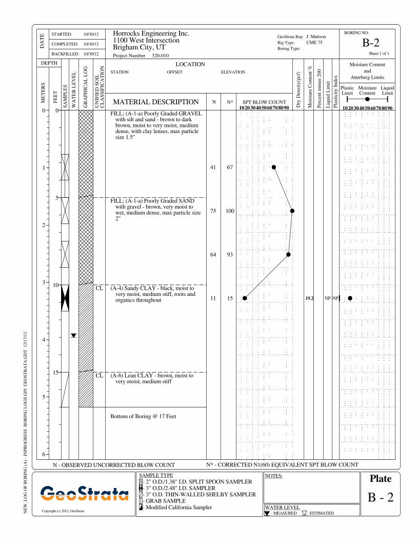
FILL; (A-1-a) Poorly Graded GRAVELwith silt and sand - brown to darkbrown, moist to very moist, mediumdense, with clay lenses, max particlesize 1.5"
19.2
Bottom of Boring @ 17 Feet
(A-6) Lean CLAY - brown, moist tovery moist, medium stiff
(A-4) Sandy CLAY - black, moist tovery moist, medium stiff, roots andorganics throughout
FILL; (A-1-a) Poorly Graded SANDwith gravel - brown, very moist towet, medium dense, max particle size2"
67
11
64
75
41
15
100
CL
CL
NP19.2
93
Liq
uid
Lim
it
DEPTHS
AM
PL
ES
102030405060708090
N - OBSERVED UNCORRECTED BLOW COUNT
STATION
SPT BLOW COUNT
Copyright (c) 2012, GeoStrata
Plate
0
1
2
3
4
5
6
ELEVATION
J. Mattson
CME 75
Horrocks Engineering Inc.1100 West IntersectionBrigham City, UT
B - 2
10/30/12
10/30/12
10/30/12
UN
IFIE
D S
OIL
CL
AS
SIF
ICA
TIO
N
GeoStrata Rep:
Rig Type:
Boring Type:
0
5
10
15
GR
AP
HIC
AL
LO
G
SAMPLE TYPE
102030405060708090
LOCATION
BORING NO:
FE
ET
OFFSET
STARTED:
COMPLETED:
BACKFILLED:
ME
TE
RS
- ESTIMATED
MoistureContent
DA
TE
N
LiquidLimit
NP
Per
cen
t m
inu
s 2
00
Dry
Den
sity
(pcf
)
PlasticLimit
WA
TE
R L
EV
EL
Mo
istu
re C
on
ten
t %
Moisture Content
and
Atterberg Limits
SPT BLOW COUNTN*MATERIAL DESCRIPTION
Project Number 320-010
Pla
stic
ity
In
dex
Sheet 1 of 1
NE
W_L
OG
OF
BO
RIN
G (
A)
- IN
PR
OG
RE
SS
B
OR
ING
LO
GS
.GP
J G
EO
ST
RA
TA
.GD
T
12/1
7/1
2
N* - CORRECTED N1(60) EQUIVALENT SPT BLOW COUNT
- 2" O.D./1.38" I.D. SPLIT SPOON SAMPLER- 3" O.D./2.48" I.D. SAMPLER- 3" O.D. THIN-WALLED SHELBY SAMPLER- GRAB SAMPLE- Modified California Sampler
- MEASURED
WATER LEVEL
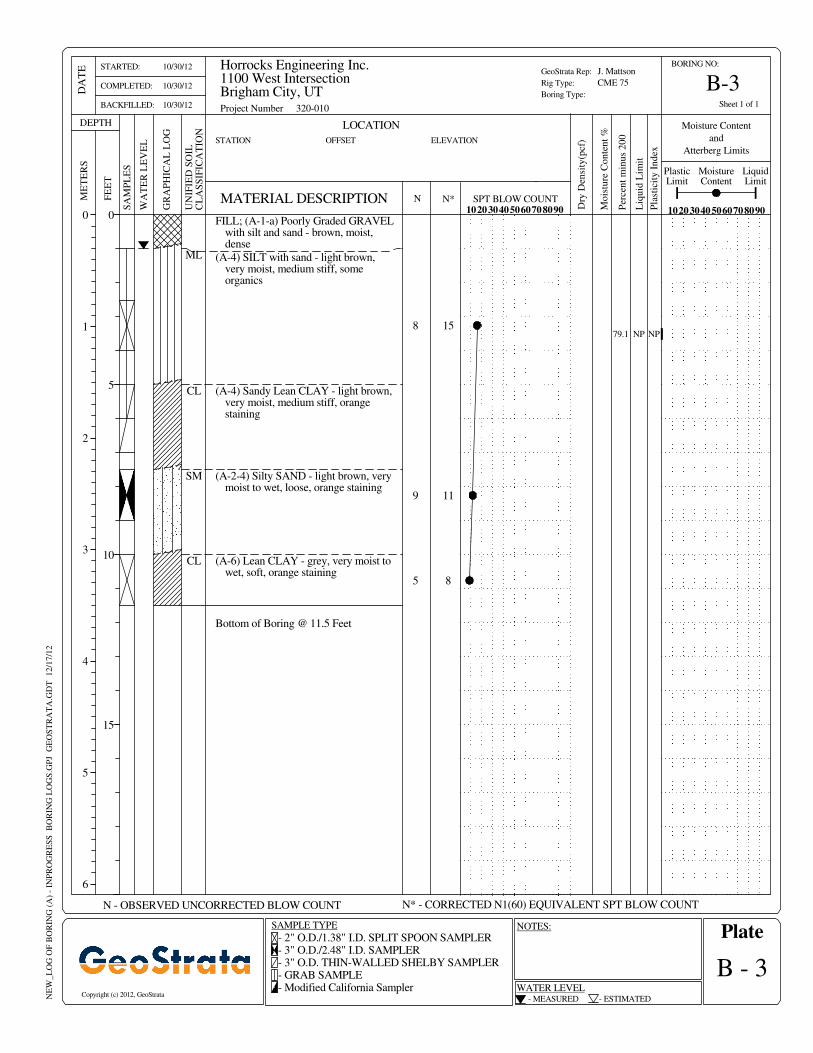
B-3
NOTES:
FILL; (A-1-a) Poorly Graded GRAVELwith silt and sand - brown, moist,dense
79.1
Bottom of Boring @ 11.5 Feet
(A-6) Lean CLAY - grey, very moist towet, soft, orange staining
(A-2-4) Silty SAND - light brown, verymoist to wet, loose, orange staining
(A-4) Sandy Lean CLAY - light brown,very moist, medium stiff, orangestaining
(A-4) SILT with sand - light brown,very moist, medium stiff, someorganics
CL
5
9
8
8
15
SM
CL
ML
NP
11
Liq
uid
Lim
it
DEPTHS
AM
PL
ES
102030405060708090
N - OBSERVED UNCORRECTED BLOW COUNT
STATION
Copyright (c) 2012, GeoStrata
Plate
0
1
2
3
4
5
6
ELEVATION
J. Mattson
CME 75
Horrocks Engineering Inc.1100 West IntersectionBrigham City, UT
B - 3
10/30/12
10/30/12
10/30/12
UN
IFIE
D S
OIL
CL
AS
SIF
ICA
TIO
N
GeoStrata Rep:
Rig Type:
Boring Type:
0
5
10
15
GR
AP
HIC
AL
LO
G
SAMPLE TYPE
102030405060708090
ME
TE
RS
BORING NO:
LOCATION
OFFSET
STARTED:
COMPLETED:
BACKFILLED:
- ESTIMATED
DA
TE
MoistureContent
N
LiquidLimit
FE
ET
B-4
LOCATION
MATERIAL DESCRIPTION
N* - CORRECTED N1(60) EQUIVALENT SPT BLOW COUNT
- 2" O.D./1.38" I.D. SPLIT SPOON SAMPLER- 3" O.D./2.48" I.D. SAMPLER- 3" O.D. THIN-WALLED SHELBY SAMPLER- GRAB SAMPLE- Modified California Sampler WATER LEVEL
NOTES:
WA
TE
R L
EV
EL
Dry
Den
sity
(pcf
)
- MEASURED
BORING NO:
NE
W_L
OG
OF
BO
RIN
G (
A)
- IN
PR
OG
RE
SS
B
OR
ING
LO
GS
.GP
J G
EO
ST
RA
TA
.GD
T
12/1
7/1
2
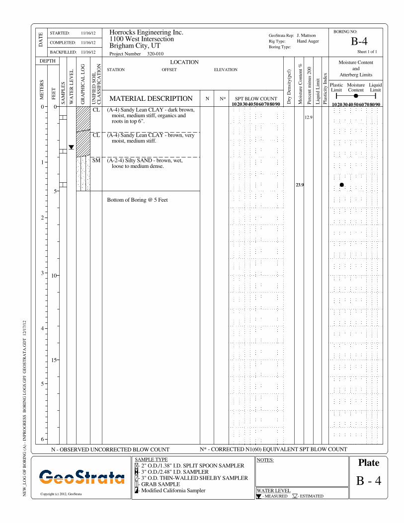
(A-4) Sandy Lean CLAY - dark brown,moist, medium stiff, organics androots in top 6".
SPT BLOW COUNT
Project Number 320-010
Pla
stic
ity
In
dex
Sheet 1 of 1F
EE
T
23.9
CL
23.9
Per
cen
t m
inu
s 2
00
Bottom of Boring @ 5 Feet
(A-2-4) Silty SAND - brown, wet,loose to medium dense.
(A-4) Sandy Lean CLAY - brown, verymoist, medium stiff.
N*
PlasticLimit
CL
SM
Mo
istu
re C
on
ten
t %
Moisture Content
and
Atterberg Limits
12.9
102030405060708090
STATION
N - OBSERVED UNCORRECTED BLOW COUNT
UN
IFIE
D S
OIL
CL
AS
SIF
ICA
TIO
N
Copyright (c) 2012, GeoStrata
SA
MP
LE
S
SAMPLE TYPE
Liq
uid
Lim
it
GeoStrata Rep:
Rig Type:
Boring Type:
DEPTH
J. Mattson
Hand Auger
Horrocks Engineering Inc.1100 West IntersectionBrigham City, UT
B - 4
102030405060708090
ELEVATION
0
5
10
15
GR
AP
HIC
AL
LO
G
- ESTIMATED
11/16/12
11/16/12
11/16/12
Plate
OFFSET
MoistureContent
ME
TE
RS
STARTED:
COMPLETED:
BACKFILLED:
0
1
2
3
4
5
6
LiquidLimit
N
DA
TE

Copyright GeoStrata , 2012
Soil Symbols Description Key
Plate
B-5
Horrocks Engineering Inc.
1100 West Intersection
Brigham City, Utah
Project Number: 320-010
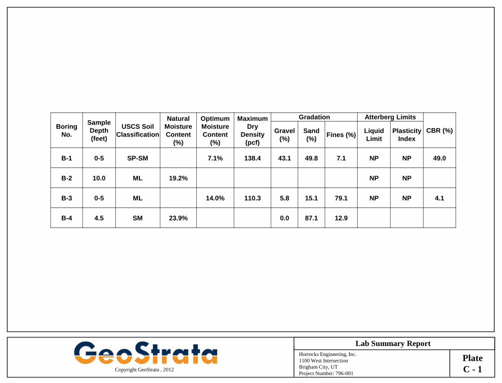
Horrocks Engineering, Inc.
1100 West Intersection
Brigham City, UT
Project Number: 796-001
Copyright GeoStrata , 2012
Lab Summary Report
Plate
C - 1
Boring
No.
Sample
Depth
(feet)
USCS Soil
Classification
Natural
Moisture
Content
(%)
Optimum
Moisture
Content
(%)
Maximum
Dry
Density
(pcf)
Gradation Atterberg Limits
CBR (%) Gravel
(%)
Sand
(%) Fines (%)
Liquid
Limit
Plasticity
Index
B-1 0-5 SP-SM 7.1% 138.4 43.1 49.8 7.1 NP NP 49.0
B-2 10.0 ML 19.2% NP NP
B-3 0-5 ML 14.0% 110.3 5.8 15.1 79.1 NP NP 4.1
B-4 4.5 SM 23.9% 0.0 87.1 12.9
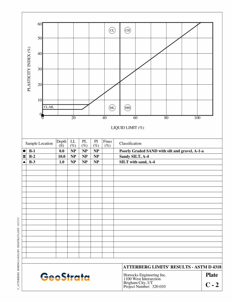
ATTERBERG LIMITS' RESULTS - ASTM D 4318
LIQUID LIMIT (%)
PL
AS
TIC
ITY
IN
DE
X (
%)
B-1
B-2
B-3
100
50
40
30
20
0 20 40 80
60
10
0
LL(%)
60
CL-ML
CL
ML MH
Sandy SILT, A-4
CH
PlateHorrocks Engineering Inc.1100 West IntersectionBrigham City, UTProject Number: 320-010 C - 2
C_A
TT
ER
BE
RG
B
OR
ING
LO
GS
.GP
J G
EO
ST
RA
TA
.GD
T
12/1
7/1
2
PL(%)
PI(%)
Fines(%)
Classification
NP
NP
NP
NP
NP
NP
NP
Depth(ft)
NP SILT with sand, A-4
Sample Location
0.0
10.0
1.0
Poorly Graded SAND with silt and gravel, A-1-a
NP
50
0.264
5.325
HYDROMETER
fine
LL
B-4
B-3
Cu
606
B-1
60
10 1 0.1 0.01 0.001
50
0.845
40
65
70
75
80
85
90
95
100
55
100
45
0
5
10
15
20
25
30
35
4.5
%Silt
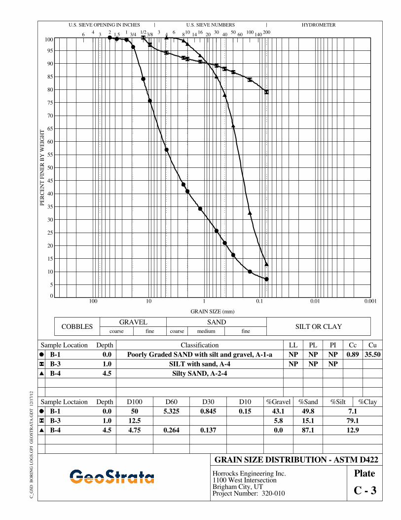
GRAIN SIZE DISTRIBUTION - ASTM D422
14
Classification
50
%Gravel
1.0
3
B-1
B-3
B-4
1003/4
0.0
NP
12.5
%Sand
NP
49.8
NP
NP
40
PE
RC
EN
T F
INE
R B
Y W
EIG
HT
GRAIN SIZE (mm)
43.1
5.8
1/2
Plate
C - 3
Horrocks Engineering Inc.1100 West IntersectionBrigham City, UTProject Number: 320-010
0.0
15.1
87.1
35.50NP
NP
3/8
Cc
2001.5
medium
68
U.S. SIEVE OPENING IN INCHES
PI
U.S. SIEVE NUMBERS
2
D10
4
D100
SILT OR CLAY
4
D30
10
%Clay
C_G
SD
B
OR
ING
LO
GS
.GP
J G
EO
ST
RA
TA
.GD
T
12/1
7/1
2
0.137
PL
Poorly Graded SAND with silt and gravel, A-1-a
Silty SAND, A-2-44.5
1403
fine coarse
20
SILT with sand, A-4
79.1
0.15
0.0
7.1
12.9
30
Sample Location Depth
Sample Loctaion Depth
GRAVEL
4.75
16
COBBLESSAND
0.89
D60
1
coarse
1.0