

HTGR Technology Course for the Nuclear Regulatory Commission
May 24 – 27, 2010
Module 5b Prismatic HTGR Nuclear Design

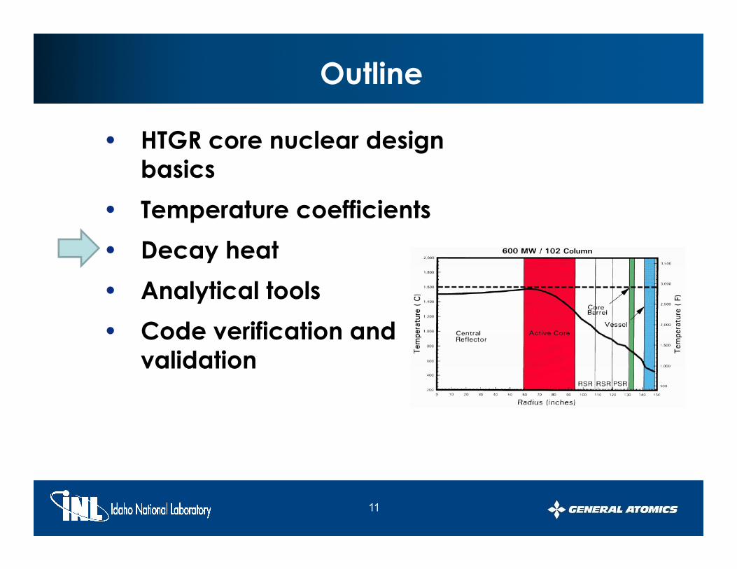
Outline
• HTGR core nuclear design b ibasics
• Temperature coefficients• Decay heat• Analytical tools• Code verification and
validation
2

HTGR Nuclear Design Shaped by System Requirements and Materials
• Graphite is the moderator and structure, not metal and
• Fuel is carbide-clad, small ceramic, particles not metal
water– High temperature solid
moderatorhard thermal spectrum
clad UO2– PyC/SiC carbide clad is primary
fission product release barrier– Fuel operates at high – hard thermal spectrum
– fixed burnable poison– Large physical dimensions– low power density
Fuel operates at high temperatures with wide margin to failure
– Double heterogeneity in physics i f f
• Helium is the coolant not water
C l t i t t t
modeling of the fuel• Modular HTGR has an annular,
not cylindrical, coreI t l d ithd – Coolant is transparent to
thermal neutrons– Coolant has no phase
changes
– In-core control rods withdrawn during startup
– Reflector rods used for control at power
3
c a ges p

HTGR Nuclear Characteristics- A Comparison -
Core Modular -
HTGR LWR
P d it / 5 8 6 6 58 105
Nuclear Properties
Power density, w/cc 5.8-6.6 58 - 105
Linear heat rate, kW/ft 1.6 19
Avg. therm-neutron energy, eV 0.22 0.17
Average Uranium Enrichment 15.5% 4.00%
Moderator (at 0.025 eV) Graphite Water
Diffusion Coefficient D, cm 0.86 0.16
Diffusion Length L, cm 54 2.75
Migration length M, cm 57 6
Collisions to thermalize ~18 ~1
Σa (cm-1) 0.00029 0.022
Σs c(m-1) 0.41 3.45
4

Use of Fixed Lumped Boron Poison (LBP)for HTGR Reactivity Control
Self shielding of the lumped boron (B4C) used to control poison burnout andpoison burnout and core reactivity behavior over a fuel cycle to minimize control rod requirements
5

Modular HTGR Fuel and LBP is Zoned to Control Power Distribution
• Fuel and burnable poison loadings are varied radially within core annular rings and axially within fuel columns (zoning)– To maintain stable power shapes with control rod
motion and fuel burnup– To keep peak fuel temperatures within p p p
acceptable limits• The uranium loading in the fuel rods
adjacent to the core/reflector boundaryadjacent to the core/reflector boundaryis reduced to minimize the reflector thermalpeaking effect
• Reflector control rods are used for reactivity control during normal operation, and the control sequence is varied for more uniform burnup, and control of power peaks
6
p p p

Outline
• HTGR core nuclear design b ibasics
• Temperature coefficients• Decay heat• Analytical tools• Code verification and
validation
7

Modular HTGR Temperature Coefficients
• Except for control rod motion, the only significant reactivity effect in modular HTGRs is that caused by reactivity effect in modular HTGRs is that caused by changes in core temperature– Helium is essentially transparent to thermal neutrons– Core dimensional changes are negligibleCore dimensional changes are negligible
• Reactivity decreases as core temperature increases– Ensures the passive safety of the systemEnsures the passive safety of the system– Large prompt negative Doppler effect from the fuel– Core moderator effect is slightly slower and negative
Reflector effect is slower small and can be slightly – Reflector effect is slower, small, and can be slightly positive
8

Modular HTGR Flux Spectrum as a Function of Operating Temperature
As core temperature I th flIncreases, the flux spectrum moves into theU-238 and Pu-240 resonance absorptionpcross section range.
9

Core Temperature Coefficient Shows Effect of Increased Resonance Absorption Over a Cycle
BOEC = Beginning of EquilibriumCycle
MOEC = Middle of EquilibriumCycleCycle
EOEC = End of Equilibrium Cycle
10
Outline
• HTGR core nuclear design basicsbasics
• Temperature coefficients• Decay heat• Decay heat• Analytical tools• Code verification and
validation
11

Modular HTGR Core Decay Heat
• Core Decay Heat calculated using 1100 nuclide depletion chain model (GARGOYLE):– Includes heavy metals, structure, impurities and fission
products– GARGOYLE (0D burnup code)has been benchmarked using G GO (0 p ) g
the ANSI LWR decay heat standard• Agreement to within 0.1% at all times
– Essentially no variation in the decay heat curve during a Essentially no variation in the decay heat curve during a cycle
– Distribution of decay heat in core and reflector calculated using Monte Carlo (MCNP)using Monte Carlo (MCNP)
– During heatup transients peak fuel and vessel temperatures reached between 80-120 hours after loss of forced circulation
12
circulation
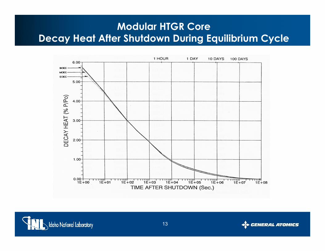
Modular HTGR Core Decay Heat After Shutdown During Equilibrium Cycle
13

Outline
• HTGR core nuclear design basicsbasics
• Temperature coefficientsD h t• Decay heat
• Analytical tools• Code verification and
validation
14
Analytic Tools Must Address Specific Prismatic HTGR Nuclear Design Issues
• Accurately model the physics of HTGR cores– Multiple heterogeneities (TRISO particle, fuel rods, graphite
blocks)– Temperature dependent neutron scattering in graphite– Cross section resonance effects
• Generate broad group cross sections that yield accurate results in diffusion and depletion calculations
Depends on local composition– Depends on local composition– Strong absorbers and interface effects– Modular HTGRs have neutronically “thin” cores (7 to 8 mean
f th )free paths)• Adequately reproduce local reaction rates
– Modeling of lumped burnable poisons
15

Analytic Tools for HTGR Prismatic Core Nuclear DesignDesign Sequence and Code Examples
Extract Pointwise Cross Sections (σs) from Nuclear Data Files(ENDF/B NJOY)
Create Multigroupσs from Pointwise Data(MICROR MICROX)
Monte Carlo calculationsBased on nuclear model
(MCNP/MonteBurns)
Scoping studies to developbasic core nuclear model input
(GARGOYLE GAUGE)
Detailed 3D deterministic analysis(DIF3D/BURP)
Post processing codes
(SORT3D)
CR worthsTemp Coeffs
Transients, etc
(SORT3D)
Core performance, T/H analysis, stress analysis, etc
16
p y y
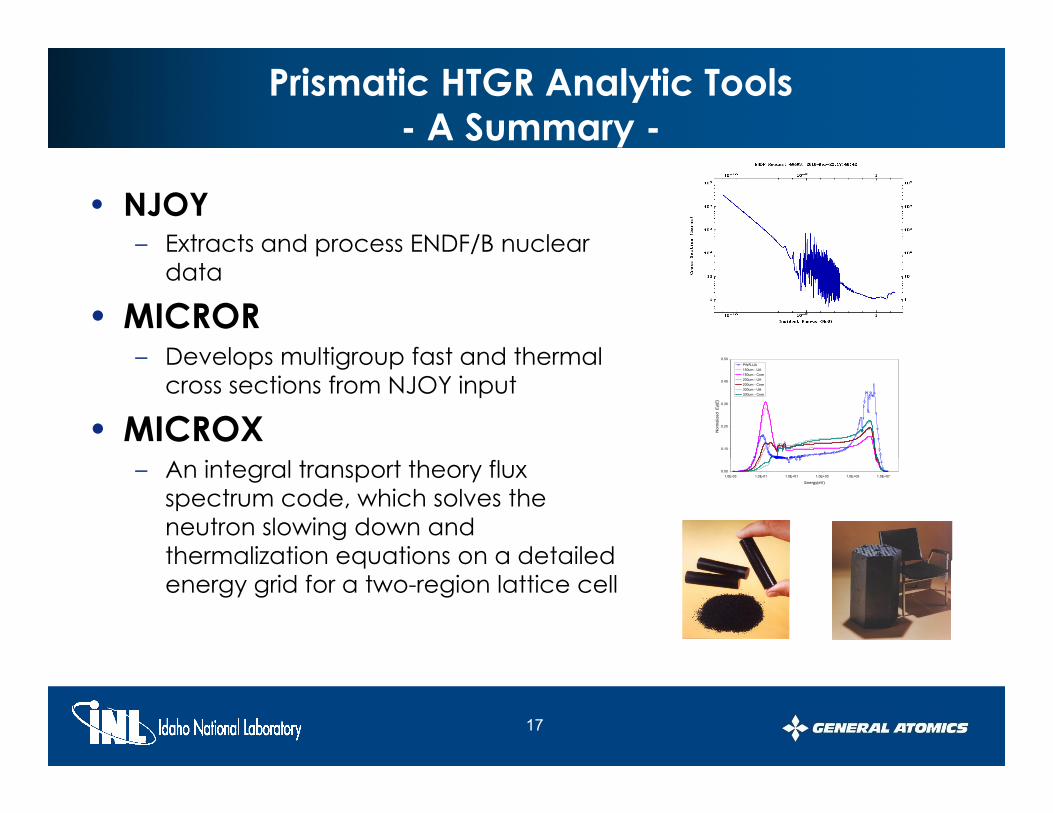
Prismatic HTGR Analytic Tools- A Summary -
• NJOY– Extracts and process ENDF/B nuclear p /
data
• MICRORDevelops multigroup fast and thermal – Develops multigroup fast and thermal cross sections from NJOY input
• MICROX0.10
0.20
0.30
0.40
0.50
Nor
mal
ized
Eφ(
E)
PWR-UA150um - UA150um - Core200um - UA200um - Core300um - UA300um - Core
– An integral transport theory flux spectrum code, which solves the neutron slowing down and thermalization equations on a detailed
0.001.0E-03 1.0E-01 1.0E+01 1.0E+03 1.0E+05 1.0E+07
Energy(eV)
thermalization equations on a detailed energy grid for a two-region lattice cell
17

Prismatic HTGR Analytic Tools- A Summary -
• GARGOYLE– 0D diffusion depletion code for determining
core segment fuel loadingscore segment fuel loadings
• GAUGE– Two-dimensional few group neutron diffusion,
triangular spatial mesh depletion codetriangular spatial mesh, depletion code– Can be used to calculate burnup histories for
large reactors with hexagonal core configurationsg
• MCNP– Radiation transport code for nuclear analysis
using Monte Carlo methodsusing Monte Carlo methods
• MonteBurns– Provides burnup capability for Monte Carlo
calculations
18
calculations

Prismatic HTGR Analytic Tools- A Summary -
• DIF3D– Solves the multigroup diffusion theory
eigenvalue adjoint fixed source and eigenvalue, adjoint, fixed source, and criticality (concentration search) problems in 1, 2, and 3 space dimensions
– Can handle orthogonal (rectangular or cylindrical), triangular and hexagonal geometries
– Core models at GA apply a nodal subhex geometrygeometry
• BURP– BURP (Burnup Replacement Package),
designed to ork in conj nction ith DIF3D
3-D animation sample(1/3rd core symmetry)
designed to work in conjunction with DIF3D– Provides core nuclide depletion capability
when used in tandem with existing static DIF3D neutron diffusion models
19

Outline
• HTGR core nuclear design basicsbasics
• Temperature coefficients• Decay heat• Decay heat• Analytical tools• Code verification and
validation
20

Code Verification and Validation (V&V)
• Verification – Ensures that a computer code correctly performs the
th ti l ti ifi d i th i l mathematical operations specified in the numerical model used
– Demonstrates substantially identical results when compared to known solutions
• Validation – Ensures that the computational method calculates the Ensures that the computational method calculates the
physical parameters of interest to within acceptable accuracy
– Calculational results compared to experimental Calculational results compared to experimental data, benchmark calculations, or results from other validated codes
21
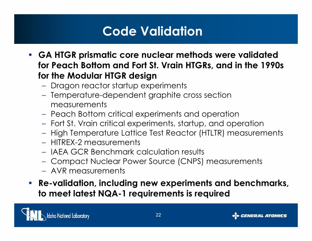
Code Validation• GA HTGR prismatic core nuclear methods were validated
for Peach Bottom and Fort St. Vrain HTGRs, and in the 1990s for the Modular HTGR designfor the Modular HTGR design– Dragon reactor startup experiments– Temperature-dependent graphite cross section
measurementsmeasurements– Peach Bottom critical experiments and operation– Fort St. Vrain critical experiments, startup, and operation– High Temperature Lattice Test Reactor (HTLTR) measurementsg p ( )– HITREX-2 measurements– IAEA GCR Benchmark calculation results– Compact Nuclear Power Source (CNPS) measurements– AVR measurements
• Re-validation, including new experiments and benchmarks, to meet latest NQA-1 requirements is required
22
o ee a es Q equ e e s s equ ed

Results of Prior Validation of GA Modular HTGR Nuclear Design Codes
Temp. C. R. Power K‐eff Water Decay Defect Worth Distr. Ingress Heat
HEU‐CORES
Facility
Peach Bottom Critical ±14% ‐11% ±10% ±0.7% DA ‐
Peach Bottom ‐11% to +4% ‐6% to +10% ±10% ±0.7% ‐ DA
HTGR Critical +6% +4% to 13% ‐ ‐0.1% to +1.0% ‐ ‐
Fort St.Vrain ‐9% to +12% ±10% ±15% ±0 5% ‐ DAFort St.Vrain 9% to +12% ±10% ±15% ±0.5% DA
HTLTR ±8% ‐ ‐ ‐ ‐ ‐
KAHTER ‐ DA DA ‐0.3% to +6% ±13% ‐
DRAGON DA ‐11% DA ‐ ‐ DA
HEU/LEU CORES
AVR ‐25% ‐5% to +15% ‐ ±11% ‐ DA
LEU CORES
HITREX‐2 ‐ ‐ ±10% ±0.5% ‐ ‐
CNPS ‐ ‐ ‐ ±0.2% ‐2% to +1% ‐
DA = Data is available, but calculations have not yet been performed by GA* (Calculation ‐ Experiment)/Experiment
23

Fort St. Vrain Nuclear Calculations Were in Excellent Agreement with Startup Measurements
• FSV Comparison Calculation/Measurement– Initial criticality 1.001Initial criticality 1.001– Core shutdown margins
• All rods in 1.03Ma rod o t 0 92• Max rod out 0.92
• Worth of 4 rod bank 0.99– Hot-to-cold swing 1.02– Core axial power distributions ± 10%– Temperature defect 1.03
D t fi f th d f • Data confirms accuracy of methods for standard fuel cycles, and will aid in validation of Modular HTGR codes
24

Accuracies Established for Early Modular HTGR 350MWt and 450MWt Nuclear Designs
PSID Allowed Calculational
Uncertainty(a)Calculated Physics Parameters
Temperature Defect ± 20% Controlrod/bank reactivity worth ± 20% Local power distributions ± 15% Core reactivity (K‐eff) ± 1.5% Core reactivity (K eff) .5%Reactivity worth of water ingress ± 25% Decay heat production ± 10%
(a) Allowed 2σ standard deviation in C/E ratio
• Allowed uncertainties based on:– Validation (C to E) results
Allowed 2σ standard deviation in C/E ratio
– Sensitivity analysis to assure that safety criteria limits for the design could be met
25

Revalidation will Include Previous Data Plus New Benchmarks and Experiments
HTTR core benchmark• Using both Monte Carlo and Deterministic modeling
30 fuel columns• 30 fuel columns• 12 replaceable reflector columns• 16 control rod columns• 3 instrumentation columns
Analytical resultsCountry Experimental
Results for the IAEA Benchmark for the HTTR
Japan Russia USA France VCS heat removal 0.2 MW 0.133 MW 0.180 MW 0.178 MW 0. 22 MW
RPV temperature ~170 oC 165 oC 159 oC ~170 oC
Analytical results Country Experimental results
9MW operation
p(EL. 19-27 m)
170 C 165 C 159 C 170 C
VCS heat removal 0.77 MW 0.494 MW 0.67 MW 0.555 MW 0.81 MW
RPV temperature (EL. 19-27 m)
370-380 oC 330-360 oC 330 oC 340-360 oC
30MW operation
26

Additional HTGR Experimental Data Available for HTR & HTR-10
HTR - PROTEUSZero-power critical facility- Graphite reflector- Core: Rc ~60 cm, H ~ 150 cm- Fuel/mod sphere: Rs = 3 cm- TRISO fuel with 5.966 g U/FS
HTR 10 (B iji )HTR -10 (Beijing)10 MW Pebble Bed Reactor- Graphite reflector- Core: Rc = 90 cm, H < 197 cmCore: Rc 90 cm, H 197 cm- TRISO fuel with 5 g U/Sphere- 17% U235
27

Additional HTGR Experimental Data Available From ASTRA Critical Facility
PurposeExperiments with reactor core cooling and heating
temperature coefficients up to 600°Cp pcritical parameterscontrol rods worthcontrol rods calibration characteristicsspatial distribution of reaction ratesspatial distribution of reaction rates
Main technical characteristicsGeometry: cylinder H/D, mm 4600/3800Fuel
- pebble bed of spherical elements with diameter, mm 60- with porosity from 0.26 up to 0.39- Quantity of fuel elements ≤ 50000- LEU with U-235 load, g/sphere 0.51- enrichment, % up to 21
StatusI ti
28
In operation

ASTRA Measurements and Planned Criticals
• ASTRA Cold Criticals– Pebble fuel– Reflector control rods
3800.0
Externalreflector
Internalreflector
Active
1800.0
1080.0
Reflector control rods– Measured
• Core reactivity• Reflector control rod worth• Individual rod worths
Activecore
• Individual rod worths• Fission rate distributions
• Phase 2 experiments planned for 2011– Core temperature to 600oC – Plan to use block fuel– Measured
• Core reactivity• Core reactivity• Reflector control rod worth• Individual rod worths• Temperature coefficient• Fission rate distributions
Channels for control and emergency protectionrodsChannels of ionization chambers and neutron counters
29
• Fission rate distributions Neutron source channel
SUMMARY• HTGR nuclear characteristics
– Physically large, but neutronically small and homogeneous– Relatively hard thermal neutron spectrumRelatively hard thermal neutron spectrum– Reactivity swing over a cycle minimized by the use of fixed,
lumped, burnable poisons• Reactivity always decreases as core temperature • Reactivity always decreases as core temperature
increases, and is the only significant reactivity effect in the core
Negative feedback effect ensures the passive safety of the – Negative feedback effect ensures the passive safety of the system
• Nuclear design codes have been developed and integrated for use on high temperature gas-cooled integrated for use on high temperature, gas-cooled reactors– Codes have been validated with data from operating
reactors and critical assemblies
30
reactors and critical assemblies

Suggested Reading
• “NGNP Point Design – Results of the Initial Neutronics and Thermal- Hydraulic Assessments Neutronics and Thermal Hydraulic Assessments During FY-03,” INEEL/EXT-03-00870, Revision 1, September 2003450MW(t) MHTGR C N l D i DOE• 450MW(t) MHTGR Core Nuclear Design, DOE-HTGR-90237, September 1993
• Reactor Physics Development Plan, DOE-HTGR-Reactor Physics Development Plan, DOE HTGR90348, Rev 0, December 1992
31


