

IAPG Natural Gas Congress
Molecular Sieves:is your regeneration procedure optimized?
CECA – VETEKAuthor Peter Meyer
Presenter Bob Davenport

IAPG 2008
A non optimized regeneration procedure can harm the molecular sieves and reduce significantly their life time
New unit: if the regeneration gas is recycled the recycled water content has to be taken in account, if the regeneration gas flow rate is too short the unit will not work
Knowing how to optimize the procedure can help debottlenecking a unit
Why optimize the regeneration procedure?

IAPG 2008
cap TSA
cap PSA
Industrial units
Regeneration: how does it work?

IAPG 2008
TSA Regeneration: how does it work?
This presentation will focus on Natural Gas Drying regenerated by Thermal Swing Adsorption (TSA).
Regeneration procedure:
1) Switch including possibly pressure change (depress.)
2) Heating (Purge? Two step heating? Heating ramp?)
3) Cooling (dry/wet gas?)
4) Switch including possibly pressure change (repress.)

IAPG 2008
Regeneration: parameters
Heating step: how much heat?
- Heat up the molecular sieves
- Heat up the vessel (internal/external insulation)
- Remove water
- Push out desorbed water

IAPG 2008
Regeneration: temperature influence
The quantity of regeneration gas depends on the inlet temperature during the heating. Below a minimum temperature the water dew point spec could not be reached (too high residual water content), the maximum temperature depends on the type of molecular sieve.
Regeneration temperature
Quantity of regeneration gas
Minimum!!

IAPG 2008
Regeneration: uncomplete regeneration
A sudden decrease of adsorption time is the sign for a bad regeneration (accumulation of water) happens very often shortly after start up, possibility to recover sieves
Adsorption cycles
Adsorption time

IAPG 2008
Regeneration: uncomplete regeneration
Make sure to have a plateau at the outlet during heating.
Make sure to have a small temperature difference between inlet and outlet during heating.
Regeneration time
Tem
per
atu
re

IAPG 2008
Regeneration: Maximum temperature
3A: 230°C (446°F) for saturated gases, up to 260°C (500°F) for unsaturated gases
4A: normally 250°C (482°F), up to 290°C (554°F) with precautions
For information
5A/13X: 300°C (572°F) in case of sweetening, but if there is NO water on the sieves

IAPG 2008
Regeneration: pressure influence
More regeneration gas (quantity) is needed if the regeneration pressure is at a high pressure.
Two cases for pressure range:
Low pressure – heating limited
The regeneration gas has to bring in the energy for heating and desorption (regeneration temperature above boiling temperature of water at regeneration pressure)
High pressure – stripping limited
The regeneration gas has additionally to strip off (push out) the desorbed water.
The limit between both is around 30-35 bars. Example: a regeneration at 60 bar (870 psia) may require perhaps 25% more regeneration gas quantity.

IAPG 2008
CASE STUDY
3 adsorber system, 2 in adsorption, 1 in regeneration
500 MMSCFD, 60 bar (870 psia), 30°C (86°F),
Saturated gas, 4A molecular sieve,
Adsorption time 16 hrs,
Regeneration recycled (air cooler sat. @ 55°C (131°F), 30 bar (435 psia))
IAPG 2008
CASE STUDY
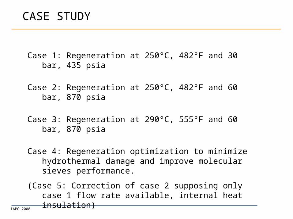
Case 1: Regeneration at 250°C, 482°F and 30 bar, 435 psia
Case 2: Regeneration at 250°C, 482°F and 60 bar, 870 psia
Case 3: Regeneration at 290°C, 555°F and 60 bar, 870 psia
Case 4: Regeneration optimization to minimize hydrothermal damage and improve molecular sieves performance.
(Case 5: Correction of case 2 supposing only case 1 flow rate available, internal heat insulation)
Fixed: pressure drop during adsorption, no stand-by time.

IAPG 2008
CASE 1
Case 1: Regeneration at 250°C, 482°F and 30 bar, 435 psia
Procedure
Depress 15 min
Heating
Cooling
Repress 15 min
7 hrs 30 min available
100% FP
Case 1
Vessel diameter : 100%
Adsorbent weight : 100%
100% FR1

IAPG 2008
CASE 2
Case 2: Regeneration at 250°C, 482°F and 60 bar, 870 psia
Procedure
Depress 0 min
Heating
Cooling
Repress 0 min
8 hrs 00 min available
30 min more
Case 2
Vessel diameter : 100%
Adsorbent weight : 104%
Regengasquantity : 123%
Heater /
Compressor -
Capacity ??100% FP
115% FR1

IAPG 2008
CASE 3
Case 3
Vessel diameter : 100%
Adsorbent weight : 102%
Regengasquantity : 115%
Case 3: Regeneration at 290°C, 482°F and 60 bar, 870 psia
Procedure
Depress 0 min
Heating
Cooling
Repress 0 min
8 hrs 00 min available
Steel: max. design
temperature ??100% FP
108% FR1

IAPG 2008
CASE STUDY
Case 1: Regeneration at 250°C, 482°F and 30 bar, 435 psia
Case 2: Regeneration at 250°C, 482°F and 60 bar, 870 psia
Case 3: Regeneration at 290°C, 555°F and 60 bar, 870 psia (possibility to reach lower dew point)
Case 4: ???
MS Quantity Regengas
quantity
Regengas
Flow rate
CASE 1 100% 100% 100% FR1
CASE 2 104% 123% 115% FR1
CASE 3 102% 115% 108% FR1
HYDROTHERMAL DAMAGING

IAPG 2008
End of Adsorption
0
2
4
6
8
10
12
14
16
18
quan
tité
adso
rbée
(g/1
00g)
ETAT FINAL DE LA COLONNE(ADSORPTION), Q_H2O
Hydrothermal damaging

IAPG 2008
Start of Heating
S1
Série1
0
20
40
60
80
100
120
140
T°C
bed length
elaps
ed
time
min
Bed Temperature ramp up
Cold saturated section
Heated section
Hydrothermal damaging

IAPG 2008
Heating proceeds ...
S 1
Série2
0
20
40
60
80
100
120
140
T ° C
bed len gt h
elapsed
time min
B ed T emper atur e r amp up
Steam Fog Formation
Cold Saturated Section
Hot Section
Hydrothermal damaging

IAPG 2008
Water Retro-condensation
during Heating
0.2
4
0.4
8
0.7
2
0.9
6
1.2
1.4
4
1.6
8
1.9
2
2.1
6
2.4
2.6
4
2.8
8
3.1
2
3.3
6
3.6
3.8
4
4.0
8
4.3
2
4.5
6
4.8
5.0
4
5.2
8
5.5
2
5.7
6
6
0.0
0.1
0.2
0.3
0.4
0.5
0.6
0.7
0.8
0.9
1.0
bed length
Retrocondesed Water in the Bed during heating
S 1
Série2
0
20
40
60
80
100
120
140
T ° C
bed len gt h
elapsed
t ime
min
B ed T emper atur e r amp up
Vaporization Zone
Condensation Zone
REFLUX
Water Droplets
Crust and Lumps formation
Hydrothermal damaging

IAPG 2008
CASE 4
Case 4: Regeneration at 290°C, 482°F and 60 bar, 870 psia
Procedure
Depress 0 min
30 min intermediate heating
Heating
Cooling
Repress 0 min
7 hrs 30 min available
Case 4
Vessel diameter : 100%
Adsorbent weight : 102%
Regengasquantity : 123%
100% FP
115% FR1

IAPG 2008
CASE STUDY
Case 1: Regeneration at 250°C, 482°F and 30 bar, 435 psia
Case 2: Regeneration at 250°C, 482°F and 60 bar, 870 psia
Case 3: Regeneration at 290°C, 555°F and 60 bar, 870 psia
Case 4: Regeneration at 290°C, 555°F and 60 bar, 870 psia, interm. heating
Advantage of case 4: lower water dew point at outlet.
MS Quantity Regengas
Quantity
Regen flow rate
CASE 1 100% 100% 100% FR1
CASE 2 104% 123% 115% FR1
CASE 3 102% 115% 108% FR1
CASE 4 102% 123% 115% FR1

IAPG 2008
CASE STUDY
Case 1: Regeneration at 250°C, 482°F and 30 bar, 435 psia
Case 2: Regeneration at 250°C, 482°F and 60 bar, 870 psia
Case 3: Regeneration at 290°C, 555°F and 60 bar, 870 psia
Case 4: Regeneration at 290°C, 555°F and 60 bar, 870 psia, interm. heating
Case 5: keep regeneration gas flow rate and MS height of case 2, internal heat insulation , diameter 3.5 m, increase feed flow rate, decrease adsorption time
MS Quantity Regengas
quantity
Regen flow rate
CASE 1 100% 100% 100% FR1
CASE 2 104% 123% 115% FR1
CASE 3 102% 115% 108% FR1
CASE 4 102% 123% 115% FR1

IAPG 2008
CASE 5 (versus case 2)
Case 2: Regeneration at 250°C, 482°F and 60 bar, 870 psia
Procedure
Depress 0 min
Heating
Cooling
Repress 0 min
4 hrs 30 min available
Adsorption 9 hrs
Case 2
Vessel diameter : 94.6%
Adsorbent weight : 88%
Regengasquantity : 61%
Pressure drop 0.7 bar
(233%)
140% FP
100% FR2

IAPG 2008
CASE STUDY
Internal insulation, 3.7m 3.5 m internal diameter
Higher feed flow rate : 140%
Higher pressure drop during adsorption : 233%
Adsorption time down from 16hrs to 9hrs (shorter life time)
MS Quantity Regengas
quantity
Regen flow rate
CASE 2 100% 100% 100% FR2
CASE 5 88% 61% 100% FR2

IAPG 2008
How to prevent hydrothermal damaging?
Hydrothermal damaging happens when liquid water is present on the molecular sieves at high temperature:
One should try to change the regeneration procedure in order to prevent desorption of water when the molsieve bed is not yet heated up almost homogenously thus limiting water condensation at top layers
intermediate heating step + higher regeneration gas flow rate

IAPG 2008
How to prevent hydrothermal damaging?
Inlet heating temperature
0
100
200
300
400
500
600
0 50 100 150 200 250
Heating time (min)
Reg
ener
atio
n
tem
per
atu
re (
°F)
Original
Instantanious water flow
0
1000
2000
3000
4000
5000
6000
0 50 100 150 200 250
R egener ati on ti me (mi n)
Original procedure:
- int. temperature too high, too much water desorbed
- plateau of outlet temperature showing water re-vaporization
Temperature at adsorber outlet
0
50
100
150
200
250
300
0 50 100 150 200 250
Time (min)

IAPG 2008
How to prevent hydrothermal damaging?
New procedure:
- int. temperature lower
- smoother increase of outlet temperature
Inlet heating temperature
0
100
200
300
400
500
600
0 50 100 150 200 250
Heating time (min)
Reg
ener
atio
n
tem
per
atu
re (
°F)
Original
CECA
Instantaneous water flow
0
1000
2000
3000
4000
5000
6000
7000
0 50 100 150 200 250
Time (min)
Temperature at adsorber outlet
0
50
100
150
200
250
300
0 50 100 150 200 250
Time (min)

IAPG 2008
How to prevent hydrothermal damaging?
Comparison for water maximum
0.00 1.00 2.00 3.00 4.00 5.00
Vessel from bottom to top
0
50
100
150
200
Original w ater
CECA w ater
Original Temperature
CECA Temperature

IAPG 2008
Conclusion
When looking at your molecular sieve unit and its regeneration procedure:
- Don’t underestimate the pressure influence on the regeneration gas quantity
- Think about hydrothermal damaging
- Optimization does not cost a lot but lengthens the life time of the molecular sieves
Don’t hesitate to ask the nice and knowledgeable guys from CECA to help you.
THANK YOU!


