
For product data sheets, visit www.cooperbussmann.com/datasheets/ulcsa 217
IEC and British Standard Fuses
IEC
&
British
Fuse
s
Application DataThe standard range of fuses for low voltage industrial andgeneral purpose applications meet the requirements of BS 88 and IEC 60269. By using advanced fuse technology, current ratings up to 400A have compact dimensions, butretain standard dimensional and performance requirements.These designs are for 315/240V systems. The standardrange of fuses are available from 2-1250A in the followingtag forms: Offset Blade - Offset Bolted - Center Bolted.
Supplementary ranges cover applications up to 660Vac and500Vdc including those with nonstandard tag fixings.
Cooper Bussmann fuses are manufactured under qualitysystems independently assessed to BS 5750 (ISO 9002) andappropriate ratings carry the ASTA 20 endorsement.
Selecting fuses is relatively simple and effective. Thefollowing notes cover the majority of applications. For furtherinformation contact our Application Engineers at636-527-1270.
Circuit Loading
The current rating of the fuse should not be less than the fullload current of the circuit. The circuit should be so designedthat small overloads of long duration will not be of frequentoccurrence.
Cable Ratings & Protection
There is an increasing move away from 70°C PVC insulationto materials that are more environmentally friendly, forexample 90°C XLPE. The ratings of fusegear, switches,accessories, etc. are generally based upon the equipmentbeing connected to conductors intended to be operated at atemperature not exceeding 70°C in normal service.
In view of the above, it is recommended that the practice ofdesigns based upon conductor temperatures of 70°C beregarded as the norm. The equipment manufacturer shouldbe consulted to ascertain the reduction of nominal currentrating of the equipment if conductor temperatures exceeding70°C are used. In addition, an overriding factor is oftenvoltage drop.
Fuses with gG characteristics protect associated cablesagainst both overload and short-circuit current, provided thatthe current rating of the fuse 1N is equal or less than thecurrent carrying capacity of the cable 1z.
In motor circuits, the motor starter will provide the overloadprotection and the fuses will provide the short-circuitprotection. The maximum fuse size that can be useddepends upon the type of cable used and is determinedusing the appropriate K factor. The following table gives themaximum sizes of fuses that are recommended for twopopular cables with copper conductors, 70°C PVC (K = 115)and 90°C thermosetting (K = 143).
Section ContentsPage
Application Data . . . . . . . . . . . . . . . . . . . . . 217-218CSA Type P and Type D fuses
(CDS, CDN & PON) . . . . . . . . . . . . . . . . . . . . . . . . . . . .219
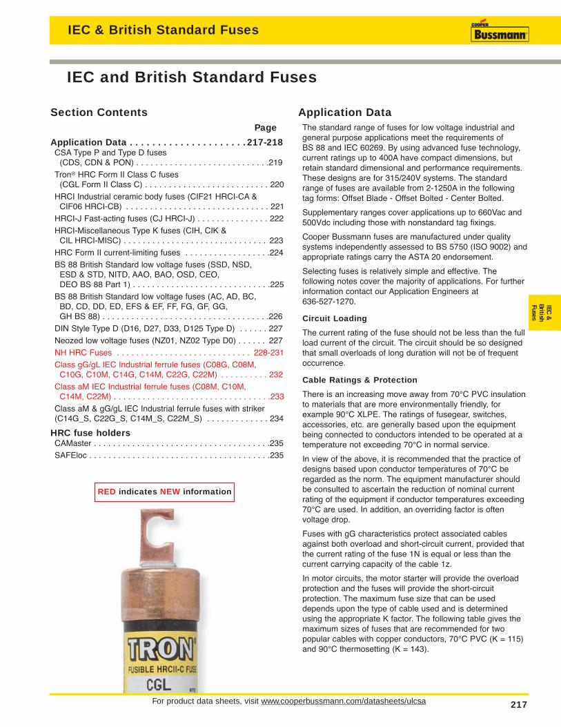
Tron® HRC Form II Class C fuses (CGL Form II Class C) . . . . . . . . . . . . . . . . . . . . . . . . . . 220
HRCI Industrial ceramic body fuses (CIF21 HRCI-CA &CIF06 HRCI-CB) . . . . . . . . . . . . . . . . . . . . . . . . . . . . . . 221
HRCI-J Fast-acting fuses (CJ HRCI-J) . . . . . . . . . . . . . . . 222
HRCI-Miscellaneous Type K fuses (CIH, CIK & CIL HRCI-MISC) . . . . . . . . . . . . . . . . . . . . . . . . . . . . . . 223
HRC Form II current-limiting fuses . . . . . . . . . . . . . . . . . .224
BS 88 British Standard low voltage fuses (SSD, NSD, ESD & STD, NITD, AAO, BAO, OSD, CEO, DEO BS 88 Part 1) . . . . . . . . . . . . . . . . . . . . . . . . . . . . .225
BS 88 British Standard low voltage fuses (AC, AD, BC, BD, CD, DD, ED, EFS & EF, FF, FG, GF, GG, GH BS 88) . . . . . . . . . . . . . . . . . . . . . . . . . . . . . . . . . . .226
DIN Style Type D (D16, D27, D33, D125 Type D) . . . . . . 227
Neozed low voltage fuses (NZ01, NZ02 Type D0) . . . . . . 227
NH HRC Fuses . . . . . . . . . . . . . . . . . . . . . . . . . . . . 228-231
Class gG/gL IEC Industrial ferrule fuses (C08G, C08M,C10G, C10M, C14G, C14M, C22G, C22M) . . . . . . . . . . 232
Class aM IEC Industrial ferrule fuses (C08M, C10M, C14M, C22M) . . . . . . . . . . . . . . . . . . . . . . . . . . . . . . . . .233
Class aM & gG/gL IEC Industrial ferrule fuses with striker(C14G_S, C22G_S, C14M_S, C22M_S) . . . . . . . . . . . . . 234
HRC fuse holdersCAMaster . . . . . . . . . . . . . . . . . . . . . . . . . . . . . . . . . . . . .235
SAFEloc . . . . . . . . . . . . . . . . . . . . . . . . . . . . . . . . . . . . . .235
RED indicates NEW information
IEC & British Standard Fuses

For product data sheets, visit www.cooperbussmann.com/datasheets/ulcsa218
Application Data for BS Low Voltage Fuses
IEC & British Standard Fuses
Max. Fuse Rating (amps)Cable Size (mm2) K = 115 K = 1431 16 161,5 20 25*2.5 32* 32*4 50* 50*6 63* 63*10 100* 125*16 125* 160*25 200* 250*35 315* 355*50 400* 50070 560 63095 710 800120 800 1000* Extended Motor Circuit dual ratings can be used.
Protection Against Electrical Shock
For a TN System, a disconnecting time not exceeding 5s ispermitted for a distribution circuit. The maximum values ofearth fault loop impedance (Zs) of 240V for CooperBussmann gG fuses to BS 88: Parts 2 and 6 are:
Rating (A) Zs (Ohms) Rating (A) Zs (Ohms) Rating (A) Zs (Ohms)6 14 50 1.1 250 0.1610 7.7 63 0.86 315 0.1316 4.3 80 0.60 400 0.09620 3.0 100 0.44 500 0.07325 2.4 125 0.35 630 0.05432 1.9 160 0.27 800 0.04440 1.4 200 0.20
Ambient Temperature
The derating, in terms of current, of 0.5% per °C above anambient of 35°C is recommended.
Interrupting Rating
The standardized interrupting rating values are 80kA forvoltages of 415Vac and above, and 40kA for DC applications. The 240Vac designs have an interrupting ratingof 50kA.
Coordination Ratio
All fuses to BS 88 Parts 2 and 6 will give a coordination ratioof 2:1; and for most practical situations a ratio of 1.6:1 (twosteps in the R10 series). Example: an upstream fuse rated at160A will coordinate with a downstream fuse rated at 100A.
Current and Energy Limitation
The range of fuses have pre-arcing I2t values towards thebottom limits of BS 88 Parts 2 and 6. This ensures excellentcurrent and energy limitation. They also have lower powerlosses at rated current. This assists in the appropriateinterchangeability with other makes of fuses.
Transformers
When fuses are used on the primary side of transformers,the normal fuse current rating should be at least twice thenominal transformer primary current.
Fluorescent Lighting
The normal fuse current rating should be at least twice thenormal full load current of the maximum number of lights tobe simultaneously switched.
Capacitor Circuits
For power factor correction in capacitor circuits, the fuseshould be chosen with a current rating greater than 1.5 timesthe rated capacitor current. This takes into account the highinrush current, circuit harmonics and capacitor tolerances.
Motor Circuits
In motor circuits, the fuse has to withstand the motor'sstarting current and often requires a higher rating than themotor's full load current. Coordination recommendations aremade by the manufacturers of motor starters in accordancewith IEC 60947-4-1. To get Type 2 coordination with fuses,tests are performed with the latest gG or gM fuses to BS 88or IEC 60269 that have pre-arcing I2t values towards the bottom of specified limits. This means that CooperBussmann fuses are suitable to provide Type 2 coordination.
Extended dual ratings of motor circuit protection fuses withgM characteristics are available in most popular fuse sizes toextend the use of associated equipment with appropriateeconomies. In the majority of applications, gG fuses areused. It is not essential to use gM fuses for motor circuitprotection, they simply extend the utilization of standardequipment.
Below is a table of recommended fuses at 415V. In mostapplications, the run-up time is less than 5 seconds and dutyis infrequent - no more than twice per hour. The next largerrating should be used for more demanding applications.
Direct On-line Asst. StartStandard Motor Circuit Standard
Rating Motor (gG) (gM) (gG)kW A A A A0.25 0.8 4 - 20.37 1.1 4 - 20.55 1.5 6 - 40.75 2.0 6 - 41.1 3 0 10 - 61.5 3.6 16 - 0 12.2 5.0 16 - 0 13.0 6.5 20 - 6 14.0 8.4 20 - 6 15.5 11.0 25 20M25 2 207.5 15.0 40 32M40 2511.0 20.0 50 32M50 3215.0 27.0 63 32M63 4018.5 33.0 80 63M80 5022.0 38.0 80 63M80 5030.0 54.0 100 63M100 8037.0 66.0 125 100M125 8045.0 79.0 160 100M160 10055.0 98.0 160 100M160 10075.0 135.0 250 200M250 16090.0 155.0 250 200M250 160110.0 185.0 315 200M315 200132.0 220.0 355 315M400 250150.0 250.0 355 315M400 315185.0 310.0 450 400M500 355200.0 335.0 500 4 00M500 400225.0 375.0 560 - 400250.0 415.0 560 - 450280.0 460.0 630 - 500335.0 562.0 710 - 630355.0 596.0 800 - 710

For product data sheets, visit www.cooperbussmann.com/datasheets/ulcsa 219
CSA Type P and Type D Fuses
IEC
&
British
Fuse
s
IEC & British Standard Fuses
Catalog NumbersBasic Catalog Dimensions in (mm)Number Amp A B Max C Min D Min E F and Volts Ratings Overall Diameter Blade Length Barrel Length Blade Thickness Blade Width
1-30 2.0 (50.8) 0.56 (14.3) — — — —35-60 3.0 (76.2) 0.81 (20.6) — — — —
CDN/PON 250Vac 70-100 5.88 (149.4) — 1.0 (25.4) — 0.13 (3.2) 0.75 (19.1)110-200 7.3 (185.4) — 1.38 (34.9) 4.13 (104.8) 0.19 (4.8) 1.13 (28.6)225-400 8.63 (219.2) — 1.88 (47.6) 4.63 (117.5) 0.25 (6.4) 1.63 (41.3)450-600 10.38 (263.7) — 2.25 (57.2) 5.19 (131.8) 0.25 (6.4) 2 (50.8)1-30 5.0 (127.0) 0.81 (20.6) — — — —35-60 5.5 (139.7) 1.06 (27.0) — — — —
CDS 600Vac 70-100 7.88 (200.2) — 1.0 (25.4) — 0.13 (3.2) 0.75 (19.1)110-200 9.63 (244.6) — 1.38 (34.9) 6.13 (115.6) 0.19 (4.8) 1.13 (28.6)225-400 11.63 (295.4) — 1.88 (47.6) 7.13 (118.1) 0.25 (6.4) 1.63 (41.3)450-600 13.38 (339.9) — 2.25 (57.2) 8.19 (208.0) 0.25 (6.4) 2 (50.8)
To OrderTo order, specify Basic Catalog Number and amp rating. Example: CDN-30
E
B
F
ADC
Knife Blade—70 through 600A
A B
Ferrule Design—1 through 60A
Data Sheet: 4126
CDS, CDN & PON Type P & D
SpecificationsDescription: CSA time-delay Type D & Pfuses.
Dimensions: See Catalog Numbers tableand Dimensions illustration.
Ratings:
Volts: — 250Vac (CDN & PON)
— 600Vac (CDS)
Amps: — 10-600A
IR: — 10kA minimum
Agency Information: CE, CSA Certified to C22.2 No. 59.1.
Features and Benefits• Economical fuse in a variety of ratings for applications not
requiring time-delay.
Typical Applications• Lighting, heating and other circuits not subject to temporary
surges and where available short-circuit current arerelatively low.
Basic Catalog Numbers
Time-Delay CSA Type “D” FusesCatalog AmpNumbers Volts Ratings
Below 10A use FRN-R 10, 12, 15, 20, 25, 30,35, 40, 45, 50, 60, 70, 80, 90, 100
CDN 250Vac 110, 125, 150, 175, 200, 225, 250, 300, 350, 400,450, 500, 600Below 10A use FRS-R 10, 12, 15, 20, 25, 30,35, 40, 45, 50, 60
CDS 600Vac 70, 80, 90, 100, 110, 125, 150, 175, 200,225, 250, 300, 350, 400, 450, 500, 600
One-Time CSA Type “P” FusesCatalog AmpNumber Volts RatingsPON 250Vac 15, 20, 25, 30, 35, 40, 45, 50, 60
Dimensions

CGL Form II Class C
SpecificationsDescription: Current-limiting HRCII-C fusesdesigned to withstand inrush currents ontypical motor start-ups while offering highcurrent limitation in the short-circuit region.Dimensions: See Dimensions illustrations.
Ratings:
Volts: — 600Vac/250Vdc (1-30A)
Amps: — 1-600A
IR: — 200kA (40,000A DC)
Agency Information: CE, CSA Certified,C22.2 No. 106.
Features and Benefits• Close sizing to loads allows using smaller and less costly
switches• Provides a higher degree of short-circuit protection• Helps protect motors against burnout from overloads
Typical Applications• For use in circuits subject to surge currents such as those
caused by motors, transformers and other inductive loads
Catalog Numbers (-Amps)CGL-1 CGL-40 CGL-175CGL-2 CGL-45 CGL-200CGL-3 CGL-50 CGL-225CGL-4 CGL-60 CGL-250CGL-6 CGL-70 CGL-300CGL-10 CGL-80 CGL-350CGL-15 CGL-90 CGL-400CGL-20 CGL-100 CGL-450CGL-25 CGL-110 CGL-500CGL-30 CGL-125 CGL-600CGL-35 CGL-150
For product data sheets, visit www.cooperbussmann.com/datasheets/ulcsa220
Tron® HRC Form II Class C Fuses
IEC & British Standard Fuses
Data Sheet: 4125
2.0"(50.8mm)2.80"
(71.04mm)3.5"
(88.9mm)
0.94"(23.81mm)
0.06"(1.59mm)2.0"
(50.8mm)2.80"
(71.04mm)3.31"
(84.14mm)
0.81"(20.64mm)
0.22"(5.56mm)
0.22"(5.56mm)
0.34"(8.73mm)
CGL 1-30
CGL 35-60
0.50"(12.7mm)
0.81"(20.64mm)
0.22"(5.56mm)
0.22"(5.56mm)
1.06"(26.92mm)
0.06"(1.59mm)
CGL 70-100
0.75"(19.05mm)
1.34"(34.04mm)
0.343"(8.71mm)
0.343"(8.71mm)
2.39"(60.72mm)
3.64"(92.47mm)
4.31"(109.54mm)
1.375"(34.93mm)
0.09"(2.29mm)
CGL 110-200
0.75"(19.05mm)
0.343(8.71mm)
0.343"(8.71mm)
3.00"(76.2mm)4.30"
(109.22mm)5.31"
(134.87mm)
1.50"(38.1mm)
0.125"(3.18mm)
CGL 225-400
1.0"(25.4mm)
0.38"(9.53mm)
3.0"(76.2mm)5.25"
(133.35mm)8.19"
(207.96mm)
2.38"(60.33mm)
0.19"(4.76mm)
1.0"(25.4mm)
CGL 450-600
0.41"(10.32mm)
3.00"(76.2mm)
1.0"(25.4mm)
1.0"(25.4mm)
0.375"(9.53mm)
3.0"(76.2mm)5.25"
(133.35mm)8.19"
(207.96mm)
.60"(15.24mm)
Dimensions

CIF21 HRCI-CA
SpecificationsDescription: The HRCI-CA fuse providesboth overload and short-circuit protection toHRCI requirements. Offset blades for bolt-onmounting. CIF21 fuse fits the CooperBussmann CAMaster fuse holder (see datasheet 4132).
Dimensions: See Dimensions illustration.
Construction: Ceramic body.
Ratings:
Volts: — 600Vac/250Vdc
Amps: — 1-30A
IR: — 200kA RMS Sym.
Agency Information: CE, CSA C22.2, No. 106-M92.
Mounting: Bolt-on.
Catalog NumbersCatalog AmpNumbers Ratings1CIF21 13CIF21 36CIF21 610CIF21 1015CIF21 1520CIF21 2025CIF21 2530CIF21 30
CIF06 HRCI-CB
SpecificationsDescription: A miniature industrial fuse thatprovides both short-circuit and overload protection and the CIF06 fits the 30ASAFEloc fuse holder.
Dimensions: See Dimensions illustration.
Construction: Ground ceramic body withplated end caps.
Ratings:
Volts: — 600Vac/250Vdc
Amps: — 1-30A
IR: — 200kA RMS Sym.
Agency Information: CE, CSA C22.2 No. 106-M92 (3-30Aonly).
Mounting: Clip-in offset blades.
Catalog NumberCatalog AmpNumbers Ratings1CIF06 13CIF06 36CIF06 610CIF06 1015CIF06 1520CIF06 2025CIF06 2530CIF06 30
For product data sheets, visit www.cooperbussmann.com/datasheets/ulcsa 221
HRCI Industrial Ceramic Body Fuses
IEC
&
British
Fuse
sIEC & British Standard Fuses
Data Sheet: 4128Data Sheet: 4127
2.15 (54.5)1.44 (35.5)
1.75 (44.5)
0.19 (4.7)0.54 (13.8)
0.44 (11.1)
0.03 (0.81)
Features and Benefits• Close sizing to loads allows using smaller and less costly
switches• Provides a higher degree of short-circuit protection• Helps protect motors against burnout from overloads
Typical Applications• For use in circuits subject to surge currents such as those
caused by motors, transformers and other inductive loads
Dimensions - in (mm)
2.38 (60.4)1.44 (35.5)
0.54 (13.8)
0.14 (3.5)
0.5 (12.7)
0.03 (3.5)
Features and Benefits• Close sizing to loads allows using smaller and less costly
switches• Provides a higher degree of short-circuit protection• Helps protect motors against burnout from overloads
Typical Applications• For use in circuits subject to surge currents such as those
caused by motors, transformers and other inductive loads
Dimensions - in (mm)

CJ HRCI-J
SpecificationsDescription: HRCI-J fast-actingfuses are industrial duty fuses with the excellent current-limiting characteristics of fast-acting HRCI-Jfuses to limit damage to equipmentand installations by the thermal andmagnetic energy associated with alarge short-circuit fault current.Overload characteristics limit cabledamage due to low overload currents.
Dimensions: See Catalog Numbers table and Dimensionsillustrations.
Construction: Ceramic body fuse.
Ratings:
Volts: — 600Vac (or less), 250Vdc
Amps: — 1-600A
IR: — 200kA
Agency Information: CSA C22.2 No. 106 M92; Designedto BS 88:2, IEC 60269-2.
For product data sheets, visit www.cooperbussmann.com/datasheets/ulcsa222
HRCI-J Fast-acting Fuses
IEC & British Standard Fuses
Data Sheet: 4129
Catalog NumbersCatalog Amp Dimensions in (mm)Numbers Ratings A B C D E F G H J K1CJ 13CJ 36CJ 610CJ 1015CJ 15 2.25 (57) 0.5 (12.7) 0.81 (20.6) — — — — — — —20CJ 2025CJ 2530CJ 3035CJ 3540CJ 4045CJ 45 2.38 (60) 0.63 (16) 1.06 (27) — — — — — — —50CJ 5060CJ 6070CJ 7080CJ 80 4.63 (117) 3.63 (92) 1.13 (28) 0.75 (19) 0.13 (3.2) 1 (25.4) 0.5 (12.7) 0.28 (7.1) 0.38 (9.5) 2.63 (67)90CJ 90100CJ 100110CJ 110125CJ 125150CJ 150 5.75 (146) 4.38 (111) 1.63 (41) 1.13 (28.6) 0.19 (4.8) 1.38 (35) 0.69 (17.5) 0.28 (7.1) 0.38 (9.5) 3 (76)175CJ 175200CJ 200225CJ 225250CJ 250300CJ 300 7.13 (181) 5.25 (133) 2.13 (54) 1.63 (41) 0.25 (6.3) 1.88 (47.6) 0.94 (24) 0.41 (10.3) 0.53 (13.5) 3.38 (86)350CJ 350400CJ 400450CJ 450500CJ 500 8 (203) 6 (152) 2.63 (66) 2 (51) 0.38 (9.5) 2.13 (54) 1 (25.4) 0.53 (13.5) 0.69 (17.5) 3.75 (96)600CJ 600
A
JFK
B
H
DC
E
G
AB B
C
Dimensions
1CJ to 60CJ
70CJ to 600CJ
Catalog Numbers

For product data sheets, visit www.cooperbussmann.com/datasheets/ulcsa 223
HRCI - Miscellaneous Type K Fuses
IEC
&
British
Fuse
sIEC & British Standard Fuses
Dimensions
Data Sheet: 4130
CIH, CIK & CIL HRCI-MISC
SpecificationsDescription: HRI fuses provide both overloadand short-circuit protection, featuring offsetblades for bolt down mounting.
Dimensions: See Catalog Numbers table andDimensions illustration.
Construction: Ceramic body.
Ratings:
Volts: — 600V
Amps: — 1-100A
IR: — 200kA@600V
Agency Information: CE, CSA C22.2 No.106 M92.
E
G
G
H
DK
FA
LC
J
B
(The CIL14 has a rejection hole, not a slot as shown above.)
Fuse Fuse Holder1-30A CM30CF35-60A CM60CF
Catalog Numbers
Catalog Amp Dimensions: in (mm)Numbers Ratings A Max B Max C Max D Nom E Nom F Nom G Nom H Nom J Max K Nom L Max1CIH07 1 2.25 (57) 0.94 (24) 3.38 (86) 0.38 (9.2) 0.04 (1.0) 2.88 (73) 0.21 (5.2) 0.31 (8) 1 (25.4) 0.10 (2.6) 2.38 (60)3CIH07 36CIH07 610CIH07 1015CIH07 1520CIH07 2025CIH07 2530CIH07 3035CIK07 35 2.28 (58) 1.06 (27) 3.56 (91) 0.5 (12.7) 0.05 (1.2) 2.88 (73) 0.21 (5.2) 0.41 (10.5) 1.09 (28) 0.13 (3.2) 2.38 (61)40CIK07 4050CIK07 5060CIK07 6080CIL14 80 2.75 (70) 1.44 (37) 4.38 (111) 0.75 (19) 0.09 (2.5) 3.69 (94) 0.34 (8.7) 0.41 (10.5) 1.5 (38.5) — 2.91 (74)90CIL14 90100CIL14 100
2.25 (57) 0.94 (24) 3.38 (86) 0.38 (9.2) 0.04 (1.0) 2.88 (73) 0.21 (5.2) 0.31 (8) 1 (25.4) 0.10 (2.6) 2.38 (60)
2.38 (61)
2.91 (74)
0.13 (3.2)
—
1.09 (28)
1.5 (38.5)
0.41 (10.5)
0.41 (10.5)
0.21 (5.2)
0.34 (8.7)
2.88 (73)
3.69 (94)
0.05 (1.2)
0.09 (2.5)
0.5 (12.7)
0.75 (19)
3.56 (91)
4.38 (111)
1.06 (27)
1.44 (37)
2.28 (58)
2.75 (70)
Recommended Fuse Holders

HRC Form II
SpecificationsDescription: HRC Form II current-limiting fuses.
Dimensions: See CatalogNumbers table and Dimensionsillustrations.
Construction: Ceramic body.
Ratings:
Volts: — 600Vac (or less)
— 250Vdc
Amps: — 2-600A
IR: — 200kA RMS Sym.
Agency Information: CE, CSA C22.2 No.106M1992; BS 88:2, IEC 60269:2.
Typical Applications• Used to protect motor control circuits, together with
contactors and overload protection relays to provide Type 2coordination - per IEC 60947-4.
For product data sheets, visit www.cooperbussmann.com/datasheets/ulcsa224
HRC Form II Current-limiting Fuses
IEC & British Standard Fuses
Data Sheet: 4131
Catalog NumbersCatalog Amp Dimensions in (mm)Numbers Ratings A B C D E F G H J K CSA Category2H07C 2 1.38 (35) 0.56 (14) 3.38 (85) 0.38 (9) 0.06 (1.2) 2.88 (73) 0.22 (5.6) 0.31 (8) 0.56 (14) — HRCII-C4H07C 46H07C 610H07C 1015H07C 1520H07C 2025H07C 2530H07C 3040K07C 40 2.19 (56) 0.88 (22) 3.44 (87) 0.5 (13) 0.06 (1.2) 2.88 (73) 0.22 (5.6) 0.31 (8) 0.88 (22) — HRCII-C50K07C 5060K07C 6080K07CR 80 2.19 (56) 0.88 (22) 3.75 (95) 0.5 (13) 0.06 (1.2) 2.88 (73) 0.22 (5.6) 0.31 (8) 0.88 (22) — HRCII-MISC100K07CR 10080L14C 80 2.38 (60) 0.88 (21.4) 4.38 (111) 0.56 (14.3) 0.13 (3.2) 3.69 (94) 0.34 (8.7) 0.44 (11) 1 (25.4) — HRCII-C100L14C 100125M14C 125 2.56 (65) 1.5 (38) 4.38 (111) 0.75 (19) 0.09 (2.4) 3.69 (94) 0.34 (8.7) 0.44 (11) — — HRCII-MISC150M14C 150200M14C 20080L09C 80 2.38 (60) 0.88 (21.4) 5 (127) 0.56 (14) 0.13 (3.2) 4.38 (111) 0.34 (8.7) 0.44 (11) — — HRCII-MISC100L09C 100125M09C 125 2.56 (65) 1.5 (38) 5.38 (136) 0.75 (19) 0.13 (3.2) 4.38 (111) 0.34 (8.7) 0.56 (14) — — HRCII-C150M09C 150200M09C 200250P09C 250 3.06 (178) 2.31 (59) 5.38 (136) 1 (25.4) 0.19 (4.8) 4.38 (111) 0.34 (8.7) 0.5 (13) — — HRCII-MISC300P09C 300350P09C 350400P09C 400250P11C 250 3.06 (178) 2.31 (59) 8.25 (210) 1 (25.4) 0.19 (5) 5.25 (133) 0.41 (10) 0.63 (16) — 1 (25) HRCII-C300P11C 300350P11C 350400P11C 400450R11C 450 3.19 (81) 2.88 (73) 8.25 (210) 1 (25.4) 0.25 (6.3) 5.25 (133) 0.41 (10) 0.63 (16) — 1 (25) HRCII-C500R11C 500600R11C 600
ED
G
F
A
HC
J
B
E
DG
F
A
H
C
J
B
DG
C
A
F
B
E
H
F B
E
G
C
A
K
D
K
H
H07C(Offset Blades)
K07C/K07CR/L14C/M14C (Offset Blades)
L09C/M09C/P09C(Center Blades)
P11C/R11C (Center Blades)
Dimensions
1.38 (35) 0.56 (14) 3.38 (85) 0.38 (9)
0.06 (1.2) 2.88 (73) 0.22 (5.6) 0.31 (8)
0.56 (14) —
HRCII-C
HRCII-MISC
HRCII-C
HRCII-C
HRCII-C
HRCII-MISC
HRCII-MISC
—
—
—
—
—
—
—
1 (25)
1 (25)
0.88 (22)
1 (25.4)
—
—
—
—
—
—
0.44 (11)
0.56 (14)
0.5 (13)
0.63 (16)
0.34 (8.7)
0.41 (10)
3.69 (94)
4.38 (111)
5.25 (133)
0.13 (3.2)
0.09 (2.4)
0.13 (3.2)
0.19 (4.8)
0.19 (5)
0.25 (6.3)
0.5 (13)
0.56 (14.3)
0.75 (19)
0.56 (14)
0.75 (19)
1 (25.4)
3.44 (87)
3.75 (95)
4.38 (111)
5 (127)
5.38 (136)
8.25 (210)
2.19 (56) 0.88 (22)
2.38 (60) 0.88 (21.4)
1.5 (38)
1.5 (38)
2.31 (59)
2.88 (73)
2.38 (60) 0.88 (21.4)
2.56 (65)
2.56 (65)
3.19 (81)
3.06 (178)
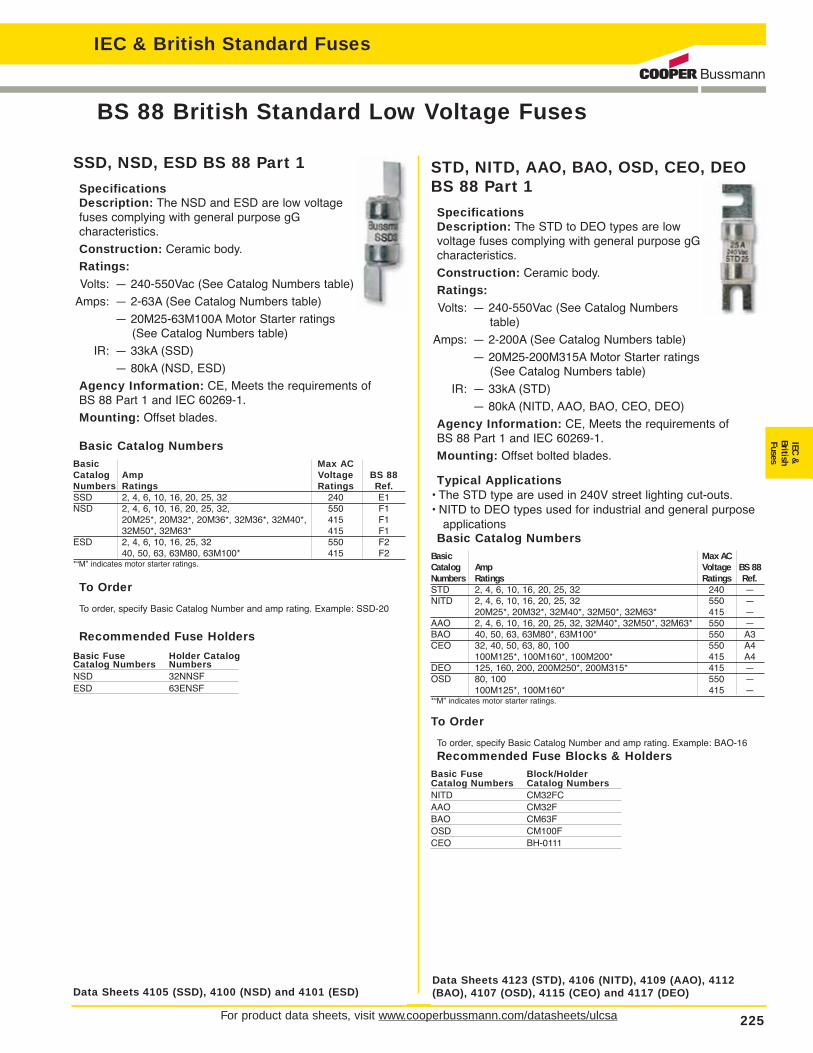
SSD, NSD, ESD BS 88 Part 1
SpecificationsDescription: The NSD and ESD are low voltagefuses complying with general purpose gG characteristics.
Construction: Ceramic body.
Ratings:
Volts: — 240-550Vac (See Catalog Numbers table)
Amps: — 2-63A (See Catalog Numbers table)
— 20M25-63M100A Motor Starter ratings (See Catalog Numbers table)
IR: — 33kA (SSD)
— 80kA (NSD, ESD)
Agency Information: CE, Meets the requirements of BS 88 Part 1 and IEC 60269-1.
Mounting: Offset blades.
Basic Catalog NumbersBasic Max ACCatalog Amp Voltage BS 88Numbers Ratings Ratings Ref.SSD 2, 4, 6, 10, 16, 20, 25, 32 240 E1NSD 2, 4, 6, 10, 16, 20, 25, 32, 550 F1
20M25*, 20M32*, 20M36*, 32M36*, 32M40*, 415 F132M50*, 32M63* 415 F1
ESD 2, 4, 6, 10, 16, 25, 32 550 F240, 50, 63, 63M80, 63M100* 415 F2
*“M” indicates motor starter ratings.
To Order
To order, specify Basic Catalog Number and amp rating. Example: SSD-20
Recommended Fuse Holders
Basic Fuse Holder CatalogCatalog Numbers NumbersNSD 32NNSFESD 63ENSF
For product data sheets, visit www.cooperbussmann.com/datasheets/ulcsa 225
BS 88 British Standard Low Voltage Fuses
IEC
&
British
Fuse
sIEC & British Standard Fuses
STD, NITD, AAO, BAO, OSD, CEO, DEO BS 88 Part 1
SpecificationsDescription: The STD to DEO types are lowvoltage fuses complying with general purpose gGcharacteristics.
Construction: Ceramic body.
Ratings:
Volts: — 240-550Vac (See Catalog Numberstable)
Amps: — 2-200A (See Catalog Numbers table)
— 20M25-200M315A Motor Starter ratings (See Catalog Numbers table)
IR: — 33kA (STD)
— 80kA (NITD, AAO, BAO, CEO, DEO)
Agency Information: CE, Meets the requirements of BS 88 Part 1 and IEC 60269-1.
Mounting: Offset bolted blades.
Typical Applications• The STD type are used in 240V street lighting cut-outs.• NITD to DEO types used for industrial and general purpose
applicationsBasic Catalog Numbers
Basic Max AC
Catalog Amp Voltage BS 88
Numbers Ratings Ratings Ref.
STD 2, 4, 6, 10, 16, 20, 25, 32 240 —NITD 2, 4, 6, 10, 16, 20, 25, 32 550 —
20M25*, 20M32*, 32M40*, 32M50*, 32M63* 415 —AAO 2, 4, 6, 10, 16, 20, 25, 32, 32M40*, 32M50*, 32M63* 550 —BAO 40, 50, 63, 63M80*, 63M100* 550 A3CEO 32, 40, 50, 63, 80, 100 550 A4
100M125*, 100M160*, 100M200* 415 A4DEO 125, 160, 200, 200M250*, 200M315* 415 —OSD 80, 100 550 —
100M125*, 100M160* 415 —*“M” indicates motor starter ratings.
To Order
To order, specify Basic Catalog Number and amp rating. Example: BAO-16
Recommended Fuse Blocks & HoldersBasic Fuse Block/HolderCatalog Numbers Catalog NumbersNITD CM32FCAAO CM32FBAO CM63FOSD CM100FCEO BH-0111
Data Sheets 4105 (SSD), 4100 (NSD) and 4101 (ESD)Data Sheets 4123 (STD), 4106 (NITD), 4109 (AAO), 4112(BAO), 4107 (OSD), 4115 (CEO) and 4117 (DEO)

EF, FF, FG, GF, GG, GHBS 88
SpecificationsDescription: Low voltage fusescomplying with general purpose gGcharacteristics and available up to400A with two hole mount and upto 1250A with four hole mount.
Construction: Ceramic body.
Ratings:
Volts: — 415/550Vac, 250/400Vdc(See Catalog Numbers table for details)
Amps: — 355-1250
IR: — See Catalog Numbers table
Agency Information: CE, Meets the requirements of BS 88 Parts 1 and 2 and IEC269-1.
Mounting: Center bolted blades, four-hole mount.
Basic Interrupting Max Voltage
Catalog Amp Ratings Ratings BS 88
Numbers Ratings AC DC AC DC Ref.
EF 355, 400 80kA — 415 — C1400M500* 80kA — 550 — —
FF 450, 500, 560, 630 80kA 40kA 550 400 C2FG 450, 500, 560, 630 80kA 40kA 550 400 —GF 710, 800 80kA 40kA 550 250 C3GG 710, 800 80kA 40kA 550 250 —
1000, 1250 80kA — 550 — —GH 710, 800, 1000, 1250 80kA — 550 — —*“M” indicates motor starter ratings.*“M” indicates motor starter ratings.
To Order
To order, specify Basic Catalog Number and amp rating. Example: FG-450
AC, AD, BC, BD, CD, DD, ED, EFS BS 88
SpecificationsDescription: Low voltage fuses thatcomply with general purpose gG characteristics and available up to 400Awith two hole mount and up to 1250Awith four hole mount.
Construction: Ceramic body.
Ratings:
Volts: — 415/550Vac, 250Vdc (SeeCatalog Numbers table)
Amps: — 2-400A (See Catalog Numbers table)
— 63M80-400M500A Motor Starter ratings (SeeCatalog Numbers table)
IR: — See Catalog Numbers table
Agency Information: CE, Meets the requirements of BS 88 Parts 1 and 2 and IEC 60269-1.
Mounting: Center bolted blades, two-hole mount.
Basic Catalog NumbersBasic Interrupting Max Voltage
Catalog Amp Ratings Ratings BS 88
Numbers Ratings AC DC AC DC Ref.
AC 2, 4, 6, 10, 16, 20, 25, 32 80kA 40kA 550 250 —AD 2, 4, 6, 10, 16, 20, 25, 32 80kA 40kA 550 250 —BC 40, 50, 63 80kA 40kA 550 250 —
63M80*, 63M100* 80kA — 550 — —BD 40, 50, 63 80kA 40kA 550 250 —CD 80, 100, 100M125*, 100M160*,
80kA — 415 — B1100M200*, 100M200*DD 125, 160, 200,
80kA — 415 — B2200M250*, 200M315*ED 250, 315, 355, 400, 315M400* 80kA — 415 — B3
400M500* 80kA — 550 — B4EFS 125, 160, 200, 250, 315 80kA 415 — —*“M” indicates motor starter ratings.
To Order
To order, specify Basic Catalog Number and amp rating. Example: BC-40
Recommended Fuse Blocks & Holder
Basic Fuse Block/HolderCatalog Numbers Catalog NumbersAC BH-0111 Modular fuse blockAD 200DF Fuse holderBC BH-0111 Modular fuse blockBD 200DF Fuse holderCD 200DF Fuse holderDD 200DF Fuse holderED BH-1131 Modular fuse block
For product data sheets, visit www.cooperbussmann.com/datasheets/ulcsa226
BS 88 British Standard Low Voltage Fuses
IEC & British Standard Fuses
Data Sheets 4110 (AC), 4111 (AD), 4113 (BC), 4114 (BD),4116 (CD), 4118 (DD), 4119 (ED) and 4121 (EFS)
Data Sheets 4120 (EF), 4102 (FF), 4122 (FG), 4103 (GF), 4104(GG) and 4108 (GH)
Basic Catalog Numbers

NZ01, NZ02 Type D0
SpecificationsDescription: Low voltage Neozed fuses suitable for use on 250Vdc systems.
Dimensions: See Catalog Numbers table andDimensions illustration.
Construction: Ceramic body.
Ratings:
Volts: — 400Vac
Amps: — 2-63A
IR: — 100kA
Agency Information: CECatalog Numbers
Catalog Amp Dimension ColorNumbers Ratings “D” (mm) Code2NZ01 2 11 Pink4NZ01 4 11 Brown6NZ01 6 11 Green10NZ01 10 11 Red16NZ01 16 11 Grey20NZ02 20 15 Blue25NZ02 25 15 Yellow35NZ02 35 15 Black50NZ02 50 15 White63NZ02 63 15 Copper
Dimensions (mm)
D16, D27, D33, D125 Type D
SpecificationsDescription: DIN style Type Dlow voltage fuses.
Dimensions: See CatalogNumbers table and Dimensionsillustrations.
Construction: Ceramic body.
Ratings:
Volts: — 500Vac
Amps: — 2-100A
IR: — 100kA
Agency Information: CE, “D” type fuses complying withDIN 49360 Part 2 and DIN 49515, operating class gL.Catalog Numbers
Catalog Amp Dimension Color FigureNumbers Ratings “D” (mm) Code Number2D16 2 6 Pink4D16 4 6 Brown6D16 6 6 Green10D16 10 8 Red 116D16 16 10 Grey20D16 20 12 Blue25D16 25 14 Yellow2D27 2 6 Pink4D27 4 6 Brown6D27 6 6 Green10D27 10 8 Red 216D27 16 10 Grey20D27 20 12 Blue25D27 25 14 Yellow35D33 35 16 Black50D33 50 18 White 363D33 63 20 Copper80D125 80 5 Silver 4100D125 100 7 RedAdditional Fuselinks: Quick acting fuselinks in body sized D16, D27, D33 and D125 rated 2-100A. Reference number suffixed Q, i.e. 10D27Q. Voltage rating 500V. Gauge rings and keys can also be supplied.
Dimensions (mm)
For product data sheets, visit www.cooperbussmann.com/datasheets/ulcsa 227
DIN Style Type D and Neozed Low Voltage Fuses
IEC
&
British
Fuse
sIEC & British Standard Fuses
Data Sheet: 4124
D
36
Data Sheet: 4124
Figure 1 Figure 2 Figure 3 Figure 4

For detailed information, visit the Electrical IEC section at www.cooperbussmann.com228
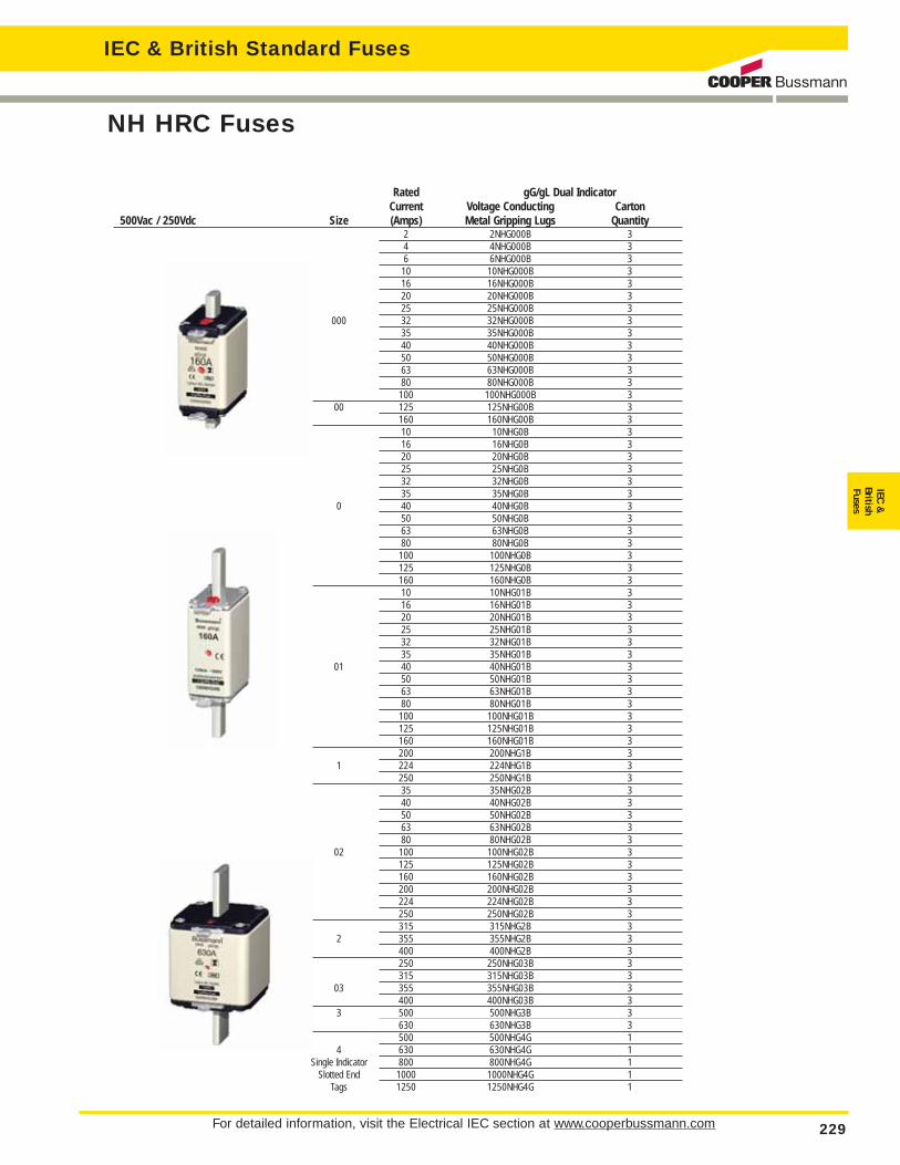
NH HRC Fuses
IEC & British Standard Fuses
___NHG___B
SpecificationsClass: gG/gL
Description: DINsquare bodied, dualindication industrialfuses.
Construction: Steatiteinsulator, corrosion-proof (aluminum) metalparts with full-contact,silver-plated copperblades.
Sizes: DIN 000 to 4.
Selectivity Ratio: 1:1.6 up to 500Vac.
Dimensions (mm)Fuse a2 b c1 c2 D e1 e2 e3 e4 fSize a1 (max) a3 a4 (nom) (± 8) (nom) (nom) (max) (max) (max) (nom) (max)000 78.5 ± 1.5 54 45 ± 1.5 49 ± 1.5 15 35 10 2 ± 0.5 41 21 16 6 800 78.5 ± 1.5 54 45 ± 1.5 49 ± 1.5 15 35 11 7.0 ± 0.5 48 30 25 6 150 125 ± 2.5 68 62 +3/-1.5 68 +1.5/-3 15 35 11 2.5 ± 0.5 48 30 25 6 1501 135 ± 2.5 75 62 ± 2.5 68 ± 2.5 15 40 11 2.5 ± 0.5 48 30 25 6 151 135 ± 2.5 75 62 ± 2.5 68 ± 2.5 20 40 11 2.5 ± 0.5 53 52 25 6 1502 150 ± 2.5 75 62 ± 2.5 68 ± 2.5 20 48 11 2.5 ± 0.5 53 52 25 6 152 150 ± 2.5 75 62 ± 2.5 68 ± 2.5 25 48 11 2.5 ± 0.5 61 60 25 6 1503 150 ± 3 75 62 ± 2.5 68 ± 2.5 25 60 11 2.5 ± 0.5 61 60 25 6 153 150 ± 3 75 62 ± 2.5 68 ± 2.5 32 60 11 3.0 ± 0.5 75 70 25 6 184 200 84 80 90 50 85 11 3 120 87 — 8 30
Ratings:
Volts: — 500Vac/250Vdc
— 690Vac/250Vdc
Amps: — 2-1250A
IR: — 120kA
Frequency: — 50Hz
Operating Frequency: — 45-62Hz
Agency Information: IEC 60269, VDE0636, DIN 43620Part 1 to 4, VDE Mark and CE.
Data Sheet 4173
Fuse Blocks SizeSB00-D 000-00SB1-D 1*, 1SB2-D 02, 2, 03, 3
For detailed information, visit the Electrical IEC section at www.cooperbussmann.com 229
NH HRC Fuses
IEC
&
British
Fuse
sIEC & British Standard Fuses
Rated gG/gL Dual IndicatorCurrent Voltage Conducting Carton
500Vac / 250Vdc Size (Amps) Metal Gripping Lugs Quantity2 2NHG000B 34 4NHG000B 36 6NHG000B 310 10NHG000B 316 16NHG000B 320 20NHG000B 325 25NHG000B 3
000 32 32NHG000B 335 35NHG000B 340 40NHG000B 350 50NHG000B 363 63NHG000B 380 80NHG000B 3100 100NHG000B 3
00 125 125NHG00B 3160 160NHG00B 310 10NHG0B 316 16NHG0B 320 20NHG0B 325 25NHG0B 332 32NHG0B 335 35NHG0B 3
0 40 40NHG0B 350 50NHG0B 363 63NHG0B 380 80NHG0B 3100 100NHG0B 3125 125NHG0B 3160 160NHG0B 310 10NHG01B 316 16NHG01B 320 20NHG01B 325 25NHG01B 332 32NHG01B 335 35NHG01B 3
01 40 40NHG01B 350 50NHG01B 363 63NHG01B 380 80NHG01B 3100 100NHG01B 3125 125NHG01B 3160 160NHG01B 3200 200NHG1B 3
1 224 224NHG1B 3250 250NHG1B 335 35NHG02B 340 40NHG02B 350 50NHG02B 363 63NHG02B 380 80NHG02B 3
02 100 100NHG02B 3125 125NHG02B 3160 160NHG02B 3200 200NHG02B 3224 224NHG02B 3250 250NHG02B 3315 315NHG2B 3
2 355 355NHG2B 3400 400NHG2B 3250 250NHG03B 3315 315NHG03B 3
03 355 355NHG03B 3400 400NHG03B 3
3 500 500NHG3B 3630 630NHG3B 3500 500NHG4G 1
4 630 630NHG4G 1Single Indicator 800 800NHG4G 1
Slotted End 1000 1000NHG4G 1Tags 1250 1250NHG4G 1

For detailed information, visit the Electrical IEC section at www.cooperbussmann.com230
IEC & British Standard Fuses
NH HRC Fuses
Rated gG/gL Dual IndicatorCurrent Voltage Conducting Carton
690Vac / 250Vdc Size (Amps) Metal Gripping Lugs Quantity2 2NHG000B-690 34 4NHG000B-690 36 6NHG000B-690 310 10NHG000B-690 3
000 16 16NHG000B-690 320 20NHG000B-690 325 25NHG000B-690 332 32NHG000B-690 335 35NHG000B-690 340 40NHG000B-690 350 50NHG00B-690 3
00 63 63NHG00B-690 380 80NHG00B-690 3100 100NHG00B-690 36 6NHG0B-690 310 10NHG0B-690 316 16NHG0B-690 320 20NHG0B-690 325 25NHG0B-690 3
0 32 32NHG0B-690 335 35NHG0B-690 340 40NHG0B-690 350 50NHG0B-690 363 63NHG0B-690 380 80NHG0B-690 3100 100NHG0B-690 350 50NHG1B-690 363 63NHG1B-690 380 80NHG1B-690 3
1 100 100NHG1B-690 3125 125NHG1B-690 3160 160NHG1B-690 3200 200NHG1B-690 363 63NHG2B-690 380 80NHG2B-690 3100 100NHG2B-690 3125 125NHG2B-690 3
2 160 160NHG2B-690 3200 200NHG2B-690 3224 224NHG2B-690 3250 250NHG2B-690 3315 315NHG2B-690 3250 250NHG3B-690 3315 315NHG3B-690 3
3 355 355NHG3B-690 3400 400NHG3B-690 3425 425NHG3B-690 3500 500NHG3B-690 3
For detailed information, visit the Electrical IEC section at www.cooperbussmann.com 231
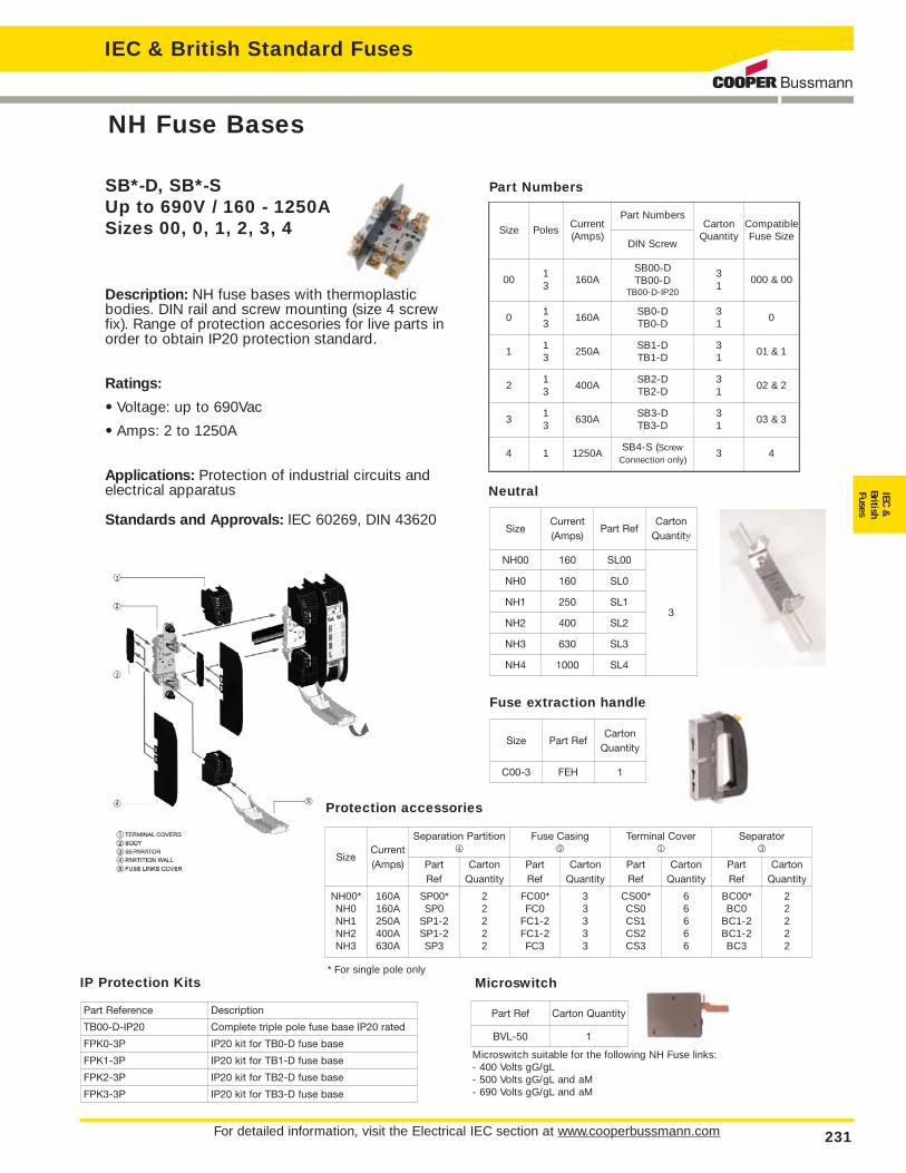
NH Fuse Bases
IEC
&
British
Fuse
sIEC & British Standard Fuses
SB*-D, SB*-S Up to 690V / 160 - 1250ASizes 00, 0, 1, 2, 3, 4
Description: NH fuse bases with thermoplastic bodies. DIN rail and screw mounting (size 4 screw fix). Range of protection accesories for live parts inorder to obtain IP20 protection standard.
Ratings:
• Voltage: up to 690Vac
• Amps: 2 to 1250A
Applications: Protection of industrial circuits andelectrical apparatus
Standards and Approvals: IEC 60269, DIN 43620
Part Numbers
Size PolesCurrent(Amps)
Part NumbersCarton
QuantityCompatibleFuse Size
DIN Screw
0013
160ASB00-DTB00-D
TB00-D-IP20
31
000 & 00
013
160ASB0-DTB0-D
31
0
113
250ASB1-DTB1-D
31
01 & 1
213
400ASB2-DTB2-D
31
02 & 2
313
630ASB3-DTB3-D
31
03 & 3
4 1 1250ASB4-S (Screw
Connection only)3 4
Neutral
SizeCurrent(Amps)
Part RefCarton
Quantity
NH00 160 SL00
3
NH0 160 SL0
NH1 250 SL1
NH2 400 SL2
NH3 630 SL3
NH4 1000 SL4
Size Part RefCarton
Quantity
C00-3 FEH 1
Fuse extraction handle
Protection accessories
SizeCurrent(Amps)
Separation Partition4
Fuse Casing5
Terminal Cover1
Separator3
PartRef
Carton Quantity
PartRef
CartonQuantity
PartRef
CartonQuantity
PartRef
CartonQuantity
NH00*NH0NH1NH2NH3
160A160A250A400A630A
SP00*SP0
SP1-2SP1-2SP3
22222
FC00*FC0
FC1-2FC1-2FC3
33333
CS00*CS0CS1CS2CS3
66666
BC00*BC0
BC1-2BC1-2BC3
22222
IP Protection Kits
Part Reference Description
TB00-D-IP20 Complete triple pole fuse base IP20 rated
FPK0-3P IP20 kit for TB0-D fuse base
FPK1-3P IP20 kit for TB1-D fuse base
FPK2-3P IP20 kit for TB2-D fuse base
FPK3-3P IP20 kit for TB3-D fuse base
Part Ref Carton Quantity
BVL-50 1
Microswitch
Microswitch suitable for the following NH Fuse links:- 400 Volts gG/gL- 500 Volts gG/gL and aM- 690 Volts gG/gL and aM
* For single pole only

For detailed information, visit the Electrical IEC section at www.cooperbussmann.com232
IEC & British Standard Fuses
Class gG/gL IEC 60269 Industrial Ferrule Fuses
8 x 31mm: 400Vac, 0.5 - 25A
10 x 38mm: 500Vac, 0.5 - 32A
14 x 51mm: 400Vac - 500Vac - 690Vac, 1 - 50A
22 x 58mm: 400Vac - 500Vac - 690Vac, 2 - 125A

For detailed information, visit the Electrical IEC section at www.cooperbussmann.com 233
Class aM IEC Industrial Ferrule Fuses - Class aM IEC60269
IEC
&
British
Fuse
sIEC & British Standard Fuses
8 x 31mm: 400Vac, 1 - 8A
10 x 38mm: 400Vac - 550Vac, 0.16 - 25A
14 x 51mm: 690Vac - 500Vac, 0.25 - 50A
22 x 58mm: 400Vac - 500Vac - 690Vac, 2 - 125A
Neutral Links

For detailed information, visit the Electrical IEC section at www.cooperbussmann.com234
IEC & British Standard Fuses
Class aM & gG/gL IEC Industrial Ferrule Fuses withStriker
Class gG/gL with StrikerCatalog Number Amp Watts Loss Voltage InterruptingWith Striker Rating (W) (AC) Rating (kA)C14G2S 2 0.24 500 120C14G4S 4 0.45C14G6S 6 0.42C14G8S 8 0.70C14G10S 10 0.53C14G12S 12 0.88C14G16S 16 1.16C14G20S 20 1.23C14G25S 25 1.46C14G32S 32 2.04C14G40S 40 3.34C14G50S 50 3.04 400Catalog Number Amp Watts Loss Voltage InterruptingWith Striker Rating (W) (AC) Rating (kA)C22G4S 4 0.48 690 80C22G6S 6 0.47C22G8S 8 0.73C22G10S 10 0.74C22G12S 12 0.83C22G16S 16 1.21C22G20S 20 1.29C22G25S 25 1.53C22G32S 32 2.13C22G40S 40 3.40C22G50S 50 3.48C22G63S 63 4.46C22G80S 80 5.86 500 120C22G100S 100 6.61C22G125S 125 8.42 400
Class aM with StrikerCatalog Number Amp Watts Loss Voltage InterruptingWith Striker Rating (W) (AC) Rating (kA)C14M1S 1 0.14 500 120C14M2S 2 0.24C14M4S 4 0.45C14M6S 6 0.42C14M8S 8 0.70C14M10S 10 0.53C14M12S 12 0.88C14M16S 16 1.16C14M20S 20 1.23C14M25S 25 1.46C14M32S 32 2.04C14M40S 40 3.34C14M50S 50 3.04 400Catalog Number Amp Watts Loss Voltage InterruptingWith Striker Rating (W) (AC) Rating (kA)C22M2S 2 0.29 690 80C22M4S 4 0.48C22M6S 6 0.47C22M8S 8 0.73C22M10S 10 0.74C22M12S 12 0.83C22M16S 16 1.21C22M20S 20 1.29C22M25S 25 1.53C22M32S 32 2.13C22M40S 40 3.40C22M50S 50 3.48C22M63S 63 4.46C22M80S 80 5.86 500 120C22M100S 100 6.61C22M125S 125 8.42 400
14 X 51
22 X 58
14 X 51
22 X 58
500 120
80
120
690
500
500 120
80
120
690
500
For product data sheets, visit www.cooperbussmann.com/datasheets/ulcsa 235
IEC
&
British
Fuse
sIEC & British Standard Fuses
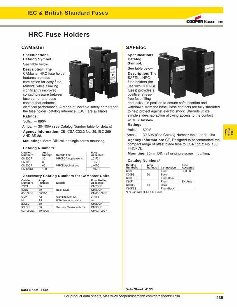
SAFEloc
SpecificationsCatalogSymbol:See table below.
Description: TheSAFEloc HRCfuse holders (foruse with HRCI-CBfuses) provides apositive, stress-free fuse fittingand locks it in position to ensure safe insertion and withdrawal from the base. Base contacts are fully shroudedto help protect against electric shock. Shrouds utilize simple slide/snap action allowing access to the contact terminal screws.
Ratings:
Volts: — 600V
Amps: — 30-60A (See Catalog Number table for details)
Agency Information: CE, Designed to accommodate thecompact range of offset blade fuse to CSA C22.2 No. 106,HRCI-CB.
Mounting: 35mm DIN rail or single screw mounting.
Catalog Numbers*Catalog Amp FuseNumbers Ratings Connection AcceptedC30F Front _CIF06C30BS 30 BackC30FBS Front-BackC60F Front EK-AmpC60BS 60 BackC60FBS Front-Back*For use with HRCI-CB Fuses.
CAMaster
SpecificationsCatalog Symbol:See table below.
Description: TheCAMaster HRC fuse holderfeatures a unique cam-action for easy fuseremoval while allowing significantly improved contact pressure betweenfuse carrier and base contact that enhances electrical performance. A range of lockable safety carriers forthe fuse holder (catalog reference: LSC), are available.
Ratings:
Volts: — 690V
Amps: — 30-100A (See Catalog Number table for details)
Agency Information: CE, CSA C22.2 No. 39; IEC 269AND BS 88.
Mounting: 35mm DIN-rail or single screw mounting.
Catalog NumbersCatalog Amp FuseNumbers Ratings Details For: AcceptedCM20CF 30 HRCI-CA Applications _CIF21CM30CF 30 _H07CCM60CF 60 HRCII Applications _K07CCM100CF 100 _K07CR
Accessory Catalog Numbers for CAMaster UnitsCatalog Amp Fuse HolderNumbers Ratings Details Accepted20BS 30 CM20CF32BS 30 Back Stud CM30CF60/100BS 60/100 CM60/100CFGLP All Ganging Link Kit 3-PoleNI All 660V Neon Indicator —20LSC 30 CM20CF30LSC 30 Security Carrier with Clip CM30CF60/100LSC 60/100A CM60/100CF
HRC Fuse Holders
Data Sheet: 4132 Data Sheet: 4133

236


