

IECU
Operating Current
Operating Voltage
Electrical Noise
Leakage Resistance
Temperature Range
Encasement
Ring Material
Brush Springs
Brush Contacts
Brush Case
Insulation
Sealing
Connectors
Current
Voltage
Bandwidth
Temperature
� Coax, twisted pair, or thermocouple wire
� Mounting flange configured to customer specifications
� Longer leads than the standard 3 ft length
7.5 amps per ring
1,000 VRMS
5 V, P-P, BW = 10Hz - 10kHz�at 8.5 mA, 500 rpm
10,000 M (min)�-30°F to 175°F
Anodized aluminum,
splash proof construction
Solid coin silver
Beryllium copper
Two 80% silver - 20% graphite
contacts per ring
Two piece, creep path grooved
Teflon and delrin
O-rings, double shaft seal
Gold plated MS Cannon
type connectors
Up to 20 amps per ring
Up to 6,000 VDC
DC to 250 MHz
Up to 250°F
STANDARD SPECIFICATIONS
OPTIONS
� Oil Well Logging
� Strain Gauge
� Thermocouple
� Packaging Machines
PART NO. C-1985
Sample Applications Include:
Our model evolved from our IEC series, the
first slip ring assembly manufactured by our company
over 40 years ago. We have provided thousands of
these units to the oil well logging industry and in the last
10 to 15 years to a number of d i fferent sectors,
inc lud ing the packaging machine indust ry.
The anodized aluminum encasement, gold plated
connector shells and double sealed shaft make it ideal
for inland applications, away from the salt air
environment. This unit mounts cant i levered
at the end of the rotating shaft using the same 2” or 4”
mounting flange as the IEL-BXU.
IECU
PART NO. C-1985-32
IEL-BXU
Operating Current
Operating Voltage
Electrical Noise
Leakage Resistance
Temperature Range
Encasement
Ring Material
Brush Springs
Brush Contacts
Brush Case
Insulation
Sealing
Connectors
7.5 amps per ring
1,000 VRMS
5 V, P-P, BW = 10Hz - 10kHz�at 8.5 mA, 500 rpm
10,000 M (min)�-30°F to 175°F
Passivated stainless steel,
splash proof construction
Solid coin silver
Beryllium copper
Four 80% silver - 20% graphite
contacts per ring
Two piece, creep path grooved
Teflon and delrin
O-rings, double shaft seal
Gold plated Bendix miniature
cylindrical type connectors
Current
Voltage
Bandwidth
Temperature
Up to 20 amps per ring
Up to 6,000 VDC
DC to 250 MHz
Up to 250°F
� Coax, twisted pair, or thermocouple wire
� Subsea applications
� Mounting flange to customer specifications
� Oil filled
� Longer leads than the standard 3 ft length
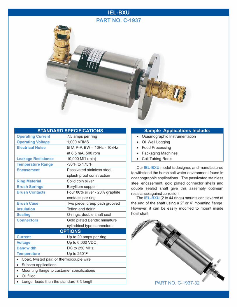
� Oceanographic Instrumentation
� Oil Well Logging
� Food Processing
� Packaging Machines
� Coil Tubing Reels
Our model is designed and manufactured
to withstand the harsh salt water environment found in
oceanographic applications. The passivated stainless
steel encasement, gold plated connector shells and
double sealed shaft give this assembly optimum
resistance against corrosion.The (2 to 44 rings) mounts cantilevered at
the end of the shaft using a 2” or 4” mounting flange.
However, it can be easily modified to mount inside
hoist shaft.
IEL-BXU
IEL-BXU
STANDARD SPECIFICATIONS
OPTIONS
PART NO. C-1937-32
PART NO. C-1937
Sample Applications Include:
IEL-BXU
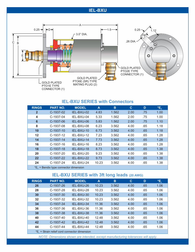
NOTE: Dimensions shown are intended, except manufacturing tolerances will apply.
IEL-BXU SERIES with 3ft long leads (20 AWG)
IEL-BXU SERIES with Connectors
*E = Strain relief cord connector dimensionL
*E = Bendix type connector dimensionC
24
22
20
18
16
14
12
10
8
6
4
2
44
42
40
38
36
34
32
30
28
26
C-1937-24
PART NO.
C-1937-22
C-1937-20
C-1937-18
C-1937-16
C-1937-14
C-1937-12
C-1937-10
C-1937-08
C-1937-06
C-1937-04
C-1937-02
IEL-BXU-06
IEL-BXU-04
IEL-BXU-02
MODEL
IEL-BXU-24
IEL-BXU-22
IEL-BXU-20
IEL-BXU-18
IEL-BXU-16
IEL-BXU-14
IEL-BXU-12
IEL-BXU-10
IEL-BXU-08
10.23
9.73
9.23
8.73
8.23
7.73
7.23
6.73
6.23
5.83
5.33
4.83
A
3.562
3.562
3.562
3.562
3.562
3.562
3.562
3.562
3.562
1.562
1.562
1.562
B
4.00
4.00
4.00
4.00
4.00
4.00
4.00
4.00
4.00
2.00
2.00
2.00
C
.65
.65
.65
.65
.65
.65
.65
.65
.65
.75
.75
.75
D
1.38
1.38
1.38
1.38
1.28
1.28
1.28
1.18
1.18
1.10
1.00
1.00
*ECRINGS
C-1937-44
C-1937-42
C-1937-40
C-1937-38
C-1937-36
C-1937-34
C-1937-32
C-1937-30
C-1937-28
C-1937-26
PART NO.
IEL-BXU-44
IEL-BXU-42
IEL-BXU-40
IEL-BXU-38
IEL-BXU-36
IEL-BXU-34
IEL-BXU-32
IEL-BXU-30
IEL-BXU-28
IEL-BXU-26
MODELRINGS
12.48
12.48
12.48
11.36
11.36
11.36
10.23
10.23
10.23
10.23
A
3.562
3.562
3.562
3.562
3.562
3.562
3.562
3.562
3.562
3.562
B
4.00
4.00
4.00
4.00
4.00
4.00
4.00
4.00
4.00
4.00
C
.65
.65
.65
.65
.65
.65
.65
.65
.65
.65
D
1.06
1.06
1.06
1.06
1.06
1.06
1.06
1.06
1.06
1.06
*EL
0.25 1.5
A
3.0” DIA.
D
GOLD PLATEDPTO6E (SR) TYPEMATING PLUG (2)
GOLD PLATEDPTO2E TYPECONNECTOR (1)
1.120.25
.26 DIA.BC
GOLD PLATEDPTO1E TYPECONNECTOR (1)
E
IECU
44
42
40
38
36
34
32
30
28
26
RINGS
C-1985-44
C-1985-42
C-1985-40
C-1985-38
C-1985-36
C-1985-34
C-1985-32
C-1985-30
C-1985-28
C-1985-26
PART NO.
IECU-44
IECU-42
IECU-40
IECU-38
IECU-36
IECU-34
IECU-32
IECU-30
IECU-28
IECU-26
MODEL
11.12
11.12
11.12
10.00
10.00
10.00
8.87
8.87
8.87
8.87
A
3.562
3.562
3.562
3.562
3.562
3.562
3.562
3.562
3.562
3.562
B
4.00
4.00
4.00
4.00
4.00
4.00
4.00
4.00
4.00
4.00
C
.87
.87
.87
.87
.87
.87
.87
.87
.87
.87
D
1.06
1.06
1.06
1.06
1.06
1.06
1.06
1.06
1.06
1.06
*EL
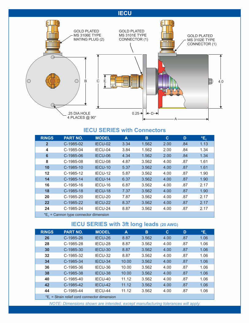
*E = Strain relief cord connector dimensionL
*E = Cannon type connector dimensionC
NOTE: Dimensions shown are intended, except manufacturing tolerances will apply.
IECU SERIES with 3ft long leads (20 AWG)
IECU SERIES with Connectors
2.17
2.17
2.17
1.90
2.17
1.90
1.90
1.61
1.61
1.34
1.34
1.13
*EC
.87
.87
.87
.87
.87
.87
.87
.87
.87
.84
.84
.84
D
4.00
4.00
4.00
4.00
4.00
4.00
4.00
4.00
4.00
2.00
2.00
2.00
C
3.562
3.562
3.562
3.562
3.562
3.562
3.562
3.562
3.562
1.562
1.562
1.562
B
8.87
8.37
7.87
7.37
6.87
6.37
5.87
5.37
4.87
4.34
3.84
3.34
A
IECU-24
IECU-22
IECU-20
IECU-18
IECU-16
IECU-14
IECU-12
IECU-10
IECU-08
IECU-06
IECU-04
IECU-02
MODEL
C-1985-24
C-1985-22
C-1985-20
C-1985-18
C-1985-16
C-1985-14
C-1985-12
C-1985-10
C-1985-08
C-1985-06
C-1985-04
C-1985-02
PART NO.
24
22
20
18
16
14
12
10
8
6
4
2
RINGS
GOLD PLATEDMS 3106E TYPEMATING PLUG (2)
GOLD PLATEDMS 3102E TYPECONNECTOR (1)
GOLD PLATEDMS 3101E TYPECONNECTOR (1)
EC
0.25
A
D
4.0
.25 DIA HOLE4 PLACES @ 90°
B

IECFCS
Operating Current
Operating Voltage
Electrical Noise
Leakage Resistance
Temperature Range
Encasement
Ring Material
Brush Springs
Brush Contacts
Brush Blocks
Insulation
Sealing
Leads
Current
Voltage
Temperature
� Stainless steel encasement parts
� Split cover to facilitate inspection
� Bore sizes up to 12”
� Leads longer than the standard 3 ft length
7.5 amps per ring
1,000 VRMS
5 V, P-P, BW = 10Hz - 10kHz�at 8.5 mA, 500 rpm
10,000 M (min)�-30°F to 175°F
Clear anodized aluminum,
splash proof construction
Solid coin silver
Beryllium copper
Four 80% silver - 20% graphite
contacts per ring
Teflon and delrin
Delrin
O-rings, v-rings on shaft
20 AWG TFE covered wire,
3 ft long
Up to 20 amps per ring
Up to 5,000 VDC
Up to 250°F
The unit expands the features of the IEL-HS
model, shown on page 9. In the standard configuration
it is designed to fit over shafts up to 8” in diameter and
up to 12” as an option. The standard is
available with 2 to 62 rings or up to an optional 300
rings.The standard bore sizes are: 1, 2, 4, 6 and 8 inches.
If your application requires a nonstandard bore size, we
will build the next larger size and install a reducing
sleeve with the required bore size for a nominal charge.
An example of a modified is illustrated on
page 16, part no. D-1350, model IECFCS-04-58-MOD.
This unit mounts over the shaft of a rotating platform
and transfers power and signals to 7 stations around its
axis.
IECFCS
IECFCS
IECFCS
This assembly can be modified to rotate up to 3,000
rpm for short periods of time. Please consult our staff
for information concerning rotational speeds.
STANDARD SPECIFICATIONS
OPTIONS
� Coil Tubing Reels
� Drive Shaft Torque Measurements
� Packaging Machines
� Food Processing Equipment
PART NO. D-1370
Sample Applications Include:

IECFCS
DIM C
DIM B
DIM A+.003-.001
5.00 6.00 8.00 10.00 12.00
2.468 3.468 5.468 7.468 9.468
1.003 2.003 4.003 6.003 8.003
Note: Dimensions shown are intended, except manufacturing tolerances will apply.
RINGS RINGS RINGS
2 24 44
4 26 46
6 28 48
8 30 50
10 32 52
12 34 54
14 36 56
16 38 58
18 40 60
20 42 62
22
D D D
2.65 6.78 10.53
3.03 7.15 10.90
3.40 7.53 11.28
3.78 7.90 11.65
4.15 8.28 12.03
4.53 8.65 12.40
4.90 9.03 12.78
5.28 9.40 13.15
5.65 9.78 13.53
6.03 10.15 13.90
6.40
E E E
4.28 8.40 12.15
4.65 8.78 12.53
5.03 9.15 12.90
5.40 9.53 13.28
5.78 9.90 13.65
6.15 10.28 14.03
6.53 10.65 14.40
6.90 11.03 14.78
7.28 11.40 15.15
7.65 11.78 15.53
8.03
0.25
.25 DIA
1.0
B
3 FT LONGLEADS BOTHENDS
1/4-20 SET SCREW4 PLACES @ 90°TYP BOTH ENDS
FOR MOUNTING PURPOSES
C
E
D
A
ORDERING INFORMATION
Example:
2.003” bore size (dim A)
16 rings
D - 1370 - 02 - 16
base part number

IEC-FR-LB
GOLD PLATEDBENDIX PT01E TYPECONNECTOR (2)
GOLD PLATEDBENDIX PT06E TYPEMATING PLUG (2)
3.0
0.25
1.25 A
3.000+.000-.002
.26 DIA HOLE4 PLACES @ 90°ON 2.500 B.C.
2.43
.26 DIA .25
1.18
Operating Current
Operating Voltage
Electrical Noise
Leakage Resistance
Temperature Range
Encasement
Ring Material
Brush Springs
Brush Contacts
Brush Blocks
Insulation
Connectors
3.0 amps per ring
500 VRMS
10,000 M (min)�-30 F to 175 F° °
Anodized aluminum
Solid coin silver
Beryllium copper
Two 80% silver - 20% graphite
contacts per ring
Delrin
Teflon and delrin
Gold plated Bendix miniature
cylindrical type connectors
B
STANDARD SPECIFICATIONS
RINGS MODEL
IEC-FR-LB-10
IEC-FR-LB-12
IEC-FR-LB-14
IEC-FR-LB-16
IEC-FR-LB-18
IEC-FR-LB-20
IEC-FR-LB-22
IEC-FR-LB-24
IEC-FR-LB-26
IEC-FR-LB-28
IEC-FR-LB-30
IEC-FR-LB-32
IEC-FR-LB-34
IEC-FR-LB-36
IEC-FR-LB-38
B
1.18
1.28
1.28
1.28
1.38
1.38
1.38
1.38
1.38
1.56
1.56
1.56
1.63
1.63
1.63
A
3.34
3.56
3.78
4.00
4.21
4.43
4.55
4.87
5.09
5.31
5.53
5.75
5.96
6.18
6.40
10
12
14
16
18
20
22
24
26
28
30
32
34
36
38
PART NO
C-1324-10
C-1324-12
C-1324-14
C-1324-16
C-1324-18
C-1324-20
C-1324-22
C-1324-24
C-1324-26
C-1324-28
C-1324-30
C-1324-32
C-1324-34
C-1324-36
C-1324-38
� Strain Gauge
� Thermocouple
� Low Output Transducers
� RTD Applications
5 V, P-P, BW = 10Hz - 10kHz�at 8.5 mA, 500 rpm
The IEC-FR-LB series is our lightweight, compact
instrumentation slip ring assembly. It can be operated
at moderately high speeds of 7,000 rpm.
NOTE: Dimensions shown are intended, except manufacturing tolerances will apply.
PART NO. C-1324
Sample Applications Include:
Current
Voltage
Up to 7.50 amps per ring
Up to 750 VDC
Temperature Up to 250°F
� Standard connectors can be replaced with leads
� 303 stainless steel rotor shaft
� Mounting flange dimensions can be increased and bolt circle
can be altered to meet customer specifications
OPTIONS

IEL-HS
STANDARD SPECIFICATIONSOperating Current
Operating Voltage
Electrical Noise
Leakage Resistance
Temperature Range
Encasement
Rotor Shaft
Ring Material
Brush Springs
Brush Contacts
Brush Blocks
Insulation
Sealing
Leads
Current
Voltage
Bandwidth
Temperature
� Stainless steel encasement parts
� Flange for cantilever mounting
� Extended shaft with or without threads
� Longer leads than the standard 3 ft length
� Coax, twisted shielded pair or thermocouple leads
7.5 amps per ring
1,000 VRMS
5 V, P-P, BW = 10Hz - 10kHz�at 8.5 mA, 500 rpm
10,000 M (min)�-30°F to 175°F
Anodized aluminum
Passivated 316 stainless steel
Solid coin silver
Beryllium copper
Two 80% silver - 20% graphite
contacts per ring
Delrin
Teflon and delrin
Splash proof construction
20 AWG TFE covered wire,
3 ft long
Up to 20 amps per ring
Up to 2,000 VDC
DC to 250 MHz
Up to 390°F
The model is designed to fit over a .375 to
1.00 inch diameter shaft. The can also be
mounted on the end of the shaft utilizing an optional
mounting flange manufactured to customer
specifications. It can be modified to accept fluid or air
swivel. The optional stainless steel encasement
makes it suitable to operate in a salt air environment.This
IEL-HS
IEL-HS
assembly can be modified to rotate up to 3,000
rpm for short periods of time. Please consult our staff
for information concerning rotational speeds.
2.25
2.75
3.25
3.75
4.25
4.75
5.25
5.75
6.25
* To complete part and model number, please insert yourdesired bore diameter.
Example:C-1635-750-08=.750 bore diameter with 8 rings
IEL-HS-*-02
IEL-HS-*-04
IEL-HS-*-06
IEL-HS-*-08
IEL-HS-*-10
IEL-HS-*-12
IEL-HS-*-14
IEL-HS-*-16
IEL-HS-*-18
C-1635-*-02
C-1635-*-04
C-1635-*-06
C-1635-*-08
C-1635-*-10
C-1635-*-12
C-1635-*-14
C-1635-*-16
C-1635-*-18
2
4
6
8
10
12
14
16
18
10-32 SET SCREW4 EQUALLY SPACEDTYP. BOTH ENDS
3 FT LEADSBOTH ENDS
.26 DIA0.25
1.18
3.00
1.50
.375-1.000
.50 A .50
� Signal Transfer
� Stress & Torque Readings
� Temperature Control
NOTE: Dimensions shown are intended, except manufacturing tolerances will apply.
�
PART NO. C-1635
Sample Applications Include:
AMODELRINGS PART NO
OPTIONS

IEL-OE
Operating Current
Operating Voltage
Electrical Noise
Leakage Resistance
Temperature Range
Encasement
Ring Material
Brush Springs
Brush Contacts
Brush Blocks
Insulation
Sealing
Leads
Current
Voltage
Bandwidth
Temperature
� Up to 300 rings
� Mounting flange configured to customer specifications
� Oil filled
� Pneumatic or hydraulic passage adapters can be added
� Fitted with certified explosion proof housing
7.5 amps per ring
1000 VRMS
5 V, P-P, BW = 10Hz - 10kHz�at 8.5 mA, 500 rpm
10,000 M (min)�-30 F to 175 F° °
Passivated stainless steel,
splash proof construction
Solid coin silver
Beryllium copper
Four 80% silver - 20% graphite
Delrin
contacts per ring
Teflon and delrin
O-rings, double shaft seal
20 AWG TEF covered wire,
6 ft long
Up to 20 amps per ring
Up to 5,000 VDC
DC to 150 MHz
Up to 250 F°
STANDARD SPECIFICATIONS
OPTIONS
� Oceanographic Instrumentation
� ROV Power/Signal Transfer
The IEL-OE
IEL-OE
assembly is rugged and versatile. It
can handle power and high frequency signals in the
same package. The passivated stainless steel
encasement and double sealed shaft make this unit
ideal for oceanographic applications. The small
housing diameter makes it possible for this unit to be
mounted inside of a shaft or mounted cantilevered at
the end of the shaft.The unit can be modified to adapt a
pneumatic or hydraulic rotary union.
The series can also be fitted with a certified
.
Visit our website for CSA certification details.
explosion proof / hazardous location housing
IEL-OE
PART NO. D-1216
Sample Applications Include:

IEL-OE
RINGS RINGS
26 74
28 76
30 78
32 80
34 82
36 84
38 86
40 88
42 90
44 92
46 94
48 96
100
102
104
106
108
110
112
114
116
118
120
50 98
52
54
56
58
60
62
64
66
68
70
72
PART NO PART NO
D-1216-26 D-1216-74
D-1216-28 D-1216-76
D-1216-30 D-1216-78
D-1216-32 D-1216-80
D-1216-34 D-1216-82
D-1216-36 D-1216-84
D-1216-38 D-1216-86
D-1216-40 D-1216-88
D-1216-42 D-1216-90
D-1216-44 D-1216-92
D-1216-46 D-1216-94
D-1216-48 D-1216-96
D-1216-50 D-1216-98
D-1216-52 D-1216-100
D-1216-54 D-1216-102
D-1216-56 D-1216-104
D-1216-58 D-1216-106
D-1216-60 D-1216-108
D-1216-62 D-1216-110
D-1216-64 D-1216-112
D-1216-66 D-1216-114
D-1216-68 D-1216-116
D-1216-70 D-1216-118
D-1216-72 D-1216-120
MODEL MODEL
IEL-OE-26 IEL-OE-74
IEL-OE-28 IEL-OE-76
IEL-OE-30 IEL-OE-78
IEL-OE-32 IEL-OE-80
IEL-OE-34 IEL-OE-82
IEL-OE-36 IEL-OE-84
IEL-OE-38 IEL-OE-86
IEL-OE-40 IEL-OE-88
IEL-OE-42 IEL-OE-90
IEL-OE-44 IEL-OE-92
IEL-OE-46 IEL-OE-94
IEL-OE-48 IEL-OE-96
IEL-OE-50 IEL-OE-98
IEL-OE-52 IEL-OE-100
IEL-OE-54 IEL-OE-102
IEL-OE-56 IEL-OE-104
IEL-OE-58 IEL-OE-106
IEL-OE-60 IEL-OE-108
IEL-OE-62 IEL-OE-110
IEL-OE-64 IEL-OE-112
IEL-OE-66 IEL-OE-114
IEL-OE-68 IEL-OE-116
IEL-OE-70 IEL-OE-118
IEL-OE-72 IEL-OE-120
A A
9.13 18.13
9.50 18.50
9.88 18.88
10.25 19.25
10.63 19.63
11.00 20.00
11.38 20.38
11.75 20.75
12.13 21.13
12.50 21.50
12.88 21.88
13.25 22.25
13.63 22.63
14.00 23.00
14.38 23.38
14.75 23.75
15.13 24.13
15.50 24.50
15.88 24.88
16.25 25.25
16.63 25.63
17.00 26.00
17.38 26.38
17.75 26.75
NOTE: Dimensions shown are intended, except manufacturing tolerances will apply.
0.18
2.25
7.5
6 FT LEADSBOTH ENDS
5.0
2.12 A
5.5
LIQUID TIGHTCONNECTORS
0.62 MOUNTING HOLES.39 DIA@ 60°
6 PLACESON 6.750 B.C.


