

III
HARGASSNER Hackgut-Pellets-Heizung A 4952 Weng OÖ Tel.: +43/7723/5274-0 Fax: +43/7723/5274-5 [email protected] 1
III O p e r a t i o n m a n u a lW o o d c h i p b o i l e r
E C O - H K 2 0 - 6 0 k W
HARGASSNER Heating technology for BiomassA 4952 Weng, Upper AustriaPhone: +43/7723/5274-0Fax: +43/7723/[email protected] BA.KE.H.20-60.ECO-HK.V03
Exactly read, follow and save these instructions
HARGASSNER Heating technology for biomass A 4952 Weng OÖ Tel.: +43/7723/5274-0 Fax: +43/7723/5274-5 [email protected] 2
ForewordChapter I: Technical data1 Type plate and CE-conformity . . . . . . . . . . . . . . . . . . . . . . . . . . I-42 Dimensions. . . . . . . . . . . . . . . . . . . . . . . . . . . . . . . . . . . . . . . . . . I-43 Intended purpose. . . . . . . . . . . . . . . . . . . . . . . . . . . . . . . . . . . . . I-44 Fuel quality . . . . . . . . . . . . . . . . . . . . . . . . . . . . . . . . . . . . . . . . . . I-55 Construction of the boiler room: . . . . . . . . . . . . . . . . . . . . . . . . I-66 Construction of the fuel storage room: . . . . . . . . . . . . . . . . . . . I-67 Execution of heating circuits . . . . . . . . . . . . . . . . . . . . . . . . . . . I-68 Back end protection . . . . . . . . . . . . . . . . . . . . . . . . . . . . . . . . . . I-69 Flue pipe - chimney dimensions . . . . . . . . . . . . . . . . . . . . . . . . I-710 Electrical connection. . . . . . . . . . . . . . . . . . . . . . . . . . . . . . . . . I-7Chapter II: Safety regulations1 General safety advices . . . . . . . . . . . . . . . . . . . . . . . . . . . . . . . II-82 Remaining risks . . . . . . . . . . . . . . . . . . . . . . . . . . . . . . . . . . . . . II-9Chapter IV: Boiler construction1 Overview of components . . . . . . . . . . . . . . . . . . . . . . . . . . . . . IV-11Chapter V: Control1 Layout of the control . . . . . . . . . . . . . . . . . . . . . . . . . . . . . . . . . V-122 Operation modes . . . . . . . . . . . . . . . . . . . . . . . . . . . . . . . . . . . V-143 Status indication of the boiler: . . . . . . . . . . . . . . . . . . . . . . . . . V-154 Menu tree - Info . . . . . . . . . . . . . . . . . . . . . . . . . . . . . . . . . . . . . V-175 Customer settings . . . . . . . . . . . . . . . . . . . . . . . . . . . . . . . . . . . V-216 Optional remote controls FR35 / FR40 (digital) and FR25 (analogue) . . . . . . . . . . . . . . . . . . . . . . . . . . . . . . . . . . . V-26Chapter VI: Commissioning 1 Checks prior commissioning . . . . . . . . . . . . . . . . . . . . . . . . . . VI-282 Start of commissioning . . . . . . . . . . . . . . . . . . . . . . . . . . . . . . . VI-28Chapter VII: Operation1 Safety instructions. . . . . . . . . . . . . . . . . . . . . . . . . . . . . . . . . . VII-292 Start-up boiler for the first time . . . . . . . . . . . . . . . . . . . . . . . VII-303 Settings recirculation (optionally) . . . . . . . . . . . . . . . . . . . . . VII-304 Inspections prior starting up the boiler . . . . . . . . . . . . . . . . . VII-30Kapitel VIII: Cleaning, Maintenance 1 Cleaning intervals . . . . . . . . . . . . . . . . . . . . . . . . . . . . . . . . . . VIII-32Chapter IX: Troubleshooting1 Errors . . . . . . . . . . . . . . . . . . . . . . . . . . . . . . . . . . . . . . . . . . . . . IX-352 List of errors. . . . . . . . . . . . . . . . . . . . . . . . . . . . . . . . . . . . . . . . IX-36Chapter X: Parameters1 Parameters Manual operation level . . . . . . . . . . . . . . . . . . . . . X-452 Installer level . . . . . . . . . . . . . . . . . . . . . . . . . . . . . . . . . . . . . . . X-493 Parameter list - Customer . . . . . . . . . . . . . . . . . . . . . . . . . . . . . X-554 Parameter list - Installer . . . . . . . . . . . . . . . . . . . . . . . . . . . . . . X-575 Parameter list - Service . . . . . . . . . . . . . . . . . . . . . . . . . . . . . . . X-596 Parameter - Setup /data logging. . . . . . . . . . . . . . . . . . . . . . . . X-63Chapter XI: Appendix7 Copyright notice . . . . . . . . . . . . . . . . . . . . . . . . . . . . . . . . . . . . XI-64
3 HARGASSNER Heating technology for biomass A 4952 Weng OÖ Tel.: +43/7723/5274-0 Fax: +43/7723/5274-5 [email protected]
Foreword
ForewordDear customer!
The AUTOMATIC WOODBIOMASS BOILER from HARGASSNER GmbH is a state of the art product and is manufactured to latest productions stand-ards.
Keep this operation manual available inside the boiler door .
The operation manual includes:• getting introduced to the boiler• and how to use this boiler according to its determination
This operation manual contains important hints, to operate the boiler• safely• appropriate• and economically
The observance of this manual helps:• Avoiding risks• Reduction of reparation costs and downtimes• Enhance the reliability and the boiler life time
Additionally to this operation manual you find:• Installation manual of the boiler• Wiring diagram and sensor overview of the boiler• Hydraulic schemes• Installation protocol and commissioning checklist• Safety sticker for the fuel storage room
0
ITechnical data
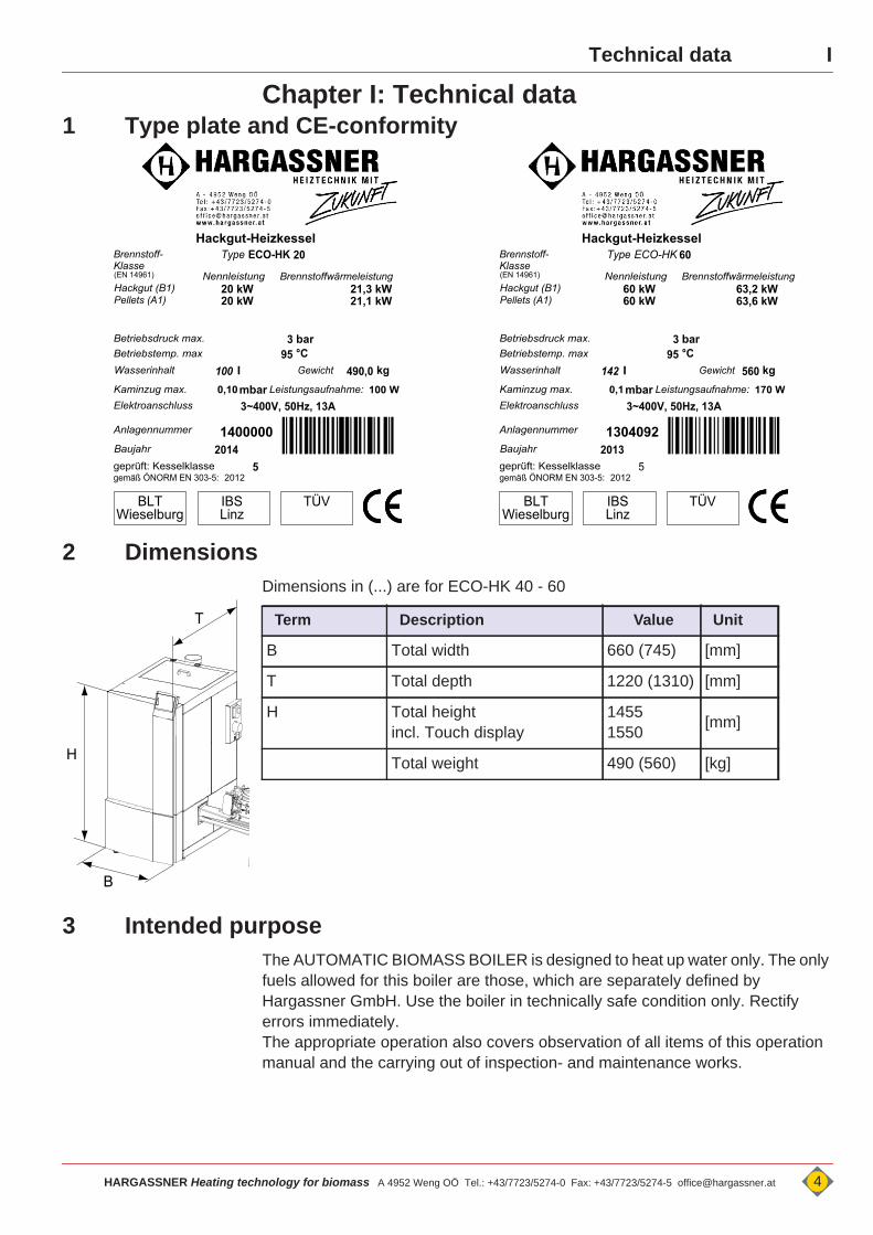
Chapter I: Technical data1 Type plate and CE-conformity
2 Dimensions Dimensions in (...) are for ECO-HK 40 - 60
3 Intended purposeThe AUTOMATIC BIOMASS BOILER is designed to heat up water only. The only fuels allowed for this boiler are those, which are separately defined by Hargassner GmbH. Use the boiler in technically safe condition only. Rectify errors immediately.The appropriate operation also covers observation of all items of this operation manual and the carrying out of inspection- and maintenance works.
mbarl
°CBetriebsdruck max. 3 barBetriebstemp. max 95Wasserinhalt 142Kaminzug max. 0,1
kg
Elektroanschluss
Anlagennummer
20131304092
3~400V, 50Hz, 13A
gemäß ÖNORM EN 303-5: 2012
BLT IBS TÜVWieselburg Linz
60
Leistungsaufnahme:
560Gewicht
ECO-HK
170 W
geprüft: Kesselklasse
Baujahr
5
Hackgut-HeizkesselTypeBrennstoff-
Klasse
60 kWHackgut (B1)Pellets (A1) 60 kW 63,6 kW
63,2 kWNennleistung Brennstoffwärmeleistung(EN 14961)
100
gemäß ÖNORM EN 303-5: 2012geprüft: Kesselklasse
(EN 14961)
BLT IBS TÜVLinzWieselburg
H
B
T Term Description Value Unit
B Total width 660 (745) [mm]
T Total depth 1220 (1310) [mm]
H Total heightincl. Touch display
14551550 [mm]
Total weight 490 (560) [kg]
HARGASSNER Heating technology for biomass A 4952 Weng OÖ Tel.: +43/7723/5274-0 Fax: +43/7723/5274-5 [email protected] 4
I Technical data
4 Fuel qualityuse fuels according to EN 14961 only
4.1 Wood chips (B1)For proper extraction of the fuel storage room and to ensure perfect combustion, use Wood chips, Class B1 according to ÖNORM EN 14961- 4:2011 only.• Water content M10 - M35• Size P16(A/B) - P31.5
4.2 Wood Pellets (A1)Ensure quality standards, when wood pellets are ordered and delivered.Quality criteria:• least possible dust content• hard and shiny surface of wood pellets• 100% natural wood, no additives, etc.• Wood pellet class A1 according to ÖNORM EN 14961-2
4.3 Miscanthus (E)For non-woody fuels like Miscanthus, also ensure quality standards.Quality criteria:• lowest possible dust-/foreign objects rate• not additives, etc.• Fuel class E according to ÖNORM EN 14961-1• Size P16(A/B) - P31.5
4.4 Inadmissible fuels• Fuels with water content >35% Formation of condensate increased risk of corrosion of the boiler
• Saw dust, grinding dust• Paper / Cardboard• Chip boards, impregnated timber• Black coal, brown coal or lignite• Waste• Plastics
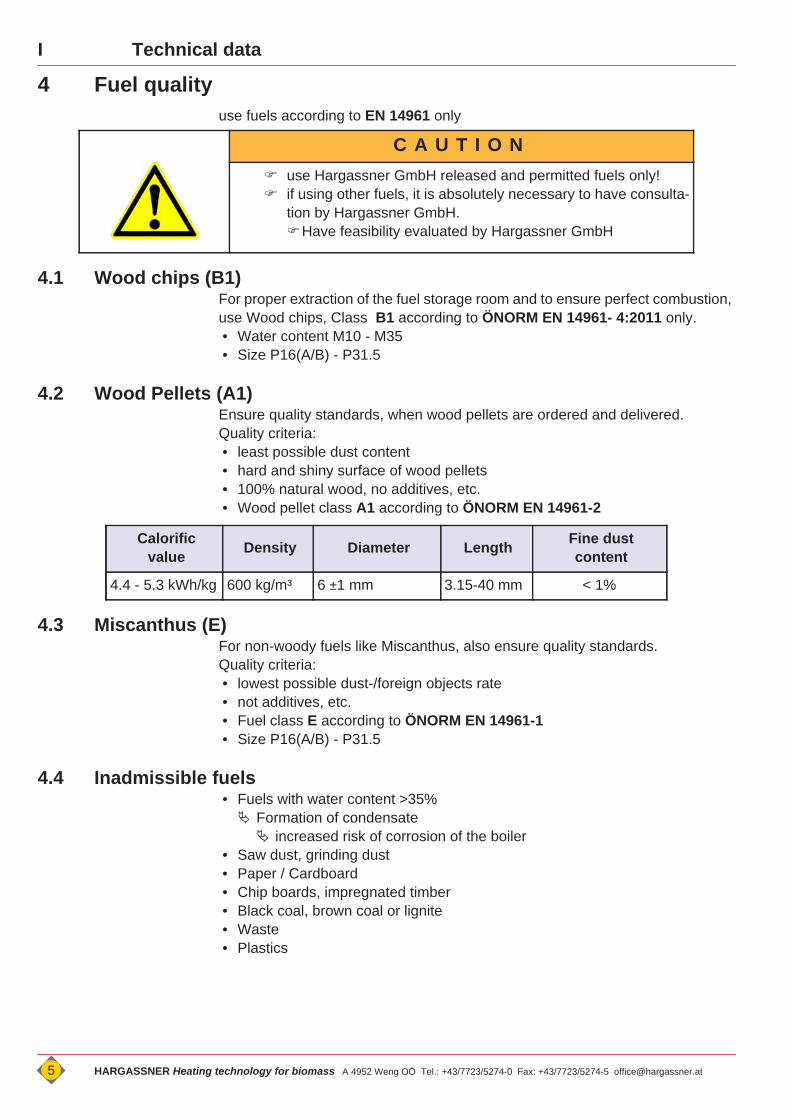
C A U T I O N use Hargassner GmbH released and permitted fuels only! if using other fuels, it is absolutely necessary to have consulta-
tion by Hargassner GmbH.Have feasibility evaluated by Hargassner GmbH
Calorific value Density Diameter Length Fine dust
content
4.4 - 5.3 kWh/kg 600 kg/m³ 6 ±1 mm 3.15-40 mm < 1%
5 HARGASSNER Heating technology for biomass A 4952 Weng OÖ Tel.: +43/7723/5274-0 Fax: +43/7723/5274-5 [email protected]
ITechnical data
5 Construction of the boiler room:Boiler room must executed according to legislation in your country. Siehe Montageanleitung “Ausführungen des Heizraumes”• Keep air openings of the boiler free.• Do not store any flammable materials in the boiler room.• Execute the boiler room in frost-proof condition.• fireproof, plane and solid floor- and ceiling construction• Correctly install heating main switch according to authorised electrician (de-
pending on building regulations).• Fire extinguisher Siehe Montageanleitung “Feuerlöscher”
6 Construction of the fuel storage room:Boiler room must executed according to legislation in your country.• No electrical installation or devices inside the storage room; all lines to be in-
stalled concealed.• Watch for sound insulation at the wall opening for the extraction auger (trans-
mission of structure-borne sound)• Protection against moisture, water and dust.
7 Execution of heating circuitsA proper execution of the heating circuits is essential for optimum operation of the boiler. See enclosed hydraulic schemesThe design of accumulators, pumps and mixing valves has to be carried out according to legislation and through a heating professional.
8 Back end protectionIf the temperature in the return is below the set value in the control an admixture of flow water takes place. The installation of a back end protection for the correct operation is mandatory. Siehe Montageanleitung “Rücklaufanhebegruppe”
D A N G E R
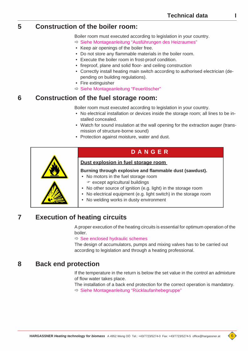
Dust explosion in fuel storage room Burning through explosive and flammable dust (sawdust).• No motors in the fuel storage room except agricultural buildings
• No other source of ignition (e.g. light) in the storage room• No electrical equipment (e.g. light switch) in the storage room• No welding works in dusty environment
HARGASSNER Heating technology for biomass A 4952 Weng OÖ Tel.: +43/7723/5274-0 Fax: +43/7723/5274-5 [email protected] 6

I Technical data
9 Flue pipe - chimney dimensions Siehe Montageanleitung “Kaminanschluss - Rauchrohr”
10 Electrical connection Siehe Montageanleitung “Elektrische Installationen” See according to electrical schematics
Dimensions in (...) are for ECO-HK 40 - 60
• the electrical connection has to be executed according to the enclosed electro-wiring diagram through a licensed and authorised electrician
• Main power switch outside of the boiler room (acc. to building regulations)• max. back-up fuse 13 A (C-Character)• capable main switch• It is absolutely imperative that the intrinsically safe cables are permanently in-
stalled • appropriate mechanical components must be selected and used
• in-phase connection L and N (see wiring diagramm)• Connect potential equalisation• use highly flexible leads (e.g. H05VV-F)
Electrical energy Characteristics Unit
Voltage 400 [V] ±5%
Frequency 50 [Hz] ±5%
Fuse 13 [A]
Power consumption 100 (170) [W]
7 HARGASSNER Heating technology for biomass A 4952 Weng OÖ Tel.: +43/7723/5274-0 Fax: +43/7723/5274-5 [email protected]
IISafety regulations
II
Chapter II: Safety regulations1 General safety advices1.1 Obligation to instruct, external personnel, children
Works on electrical equipment may only be carried out through• an professional electrician• according to electrical standards.
Work on hydraulic systems must be carried out only by personnel with specialised knowledge and experience in hydraulics!
1.2 Special measures prior commissioning through the operator• Licensing requirements for safe operation and accident prevention regulations
must be observed!• Do execute verifications prior first start up. see “Checks prior commissioning” on page 28.
• Do execute verifications prior commissioning. see “Inspections prior starting up the boiler” on page 30.
1.3 Key issuing
D A N G E R
Non-observance of the safety regulations!Death, injury, damage through inappropriate installation.• Observe safety instructions of the boiler and in the operation manual!• Exactly read the user manual PRIOR commissioning. in the cladding door is a storage compartment.
External, not authorised peopleDeath, injury, damage through inappropriate installation.• Works on the boiler through qualified and experienced personnel only. Determine
boiler supervisor.• Keep out external, not authorised and not trained people from the boiler room and
the storage room.• No transfer of control entry codes.• Observe legal minimum age of personnel.• Place prohibition sign in front of boiler room door and fuel storage door.
D A N G E RUnauthorised commissioning!Commissioning through Hargassner authorised staff only. • Prevent unauthorised commissioning. Blockmainpower switch and keep keys safe.
HARGASSNER Heating technology for biomass A 4952 Weng OÖ Tel.: +43/7723/5274-0 Fax: +43/7723/5274-5 [email protected] 8
II Safety regulations
2 Remaining risksIf the boiler is operated appropriately and professionallythe following remaining risks must be observed:
D A N G E R
Hot surfaces, hot ash!Burns through hot boiler components• Prior any maintenance works
Shut down and cool down boiler.• Do not grasp into the boiler during operation.• Wear heat resistant gloves. The ash in the ash box does save heat.
• Do not empty hot ash into dustbin. Put ash in closed, not-flammable vessels only.
Hot waterScalds through sprinkling, hot water.• Check hoses, lines and connections periodically for leakages, wear and tear or any
other damage!• Rectify damages immediately.• Prior any maintenance works on the circulation water system, de-pressurise the unit• Check, if all valves are in correct position.
D A N G E R
Dust explosion in fuel storage roomBurning through explosive and flammable dust (Pellet dust).• No motors in the fuel storage room (acc. to country-specific regulations) except agricultural buildings
• No other source of ignition (e.g. light) in the storage room• No electrical equipment (e.g. light switch) in the storage room• No welding works in dusty environment
D A N G E R
Risk of deflagration, explosion and burningBurns through explosively combustion of residual gases (CO) in the combus-tion chamber.
• Open combustion door carefully Slightly in the beginning. Hold back body and face from the combustion door To avoid any burning risks
• The risk of deflagration increases significantly after uncontrolled conditions. (e.g. power loss)
• At / after a power loss, do NOT open the combustion door• Do not open combustion door during heating operation
9 HARGASSNER Heating technology for biomass A 4952 Weng OÖ Tel.: +43/7723/5274-0 Fax: +43/7723/5274-5 [email protected]
IISafety regulations
D A N G E R
Rotating augers and moving parts in the area of the ash extraction, stoker auger and the fuel extraction!Amputation, crushing of hands through touching moving parts or augers.• Omit access to augers or motors at operating boiler.• Do not perform any works on the plant, if any other person is in the danger zone. Secure / lock fuel storage room
• Remove blockages and perform cleaning only with tools and at switched-off boiler status. Also lock <mainpower switch>.
Unpredictable operation conditions• The spring blades of the agitator system are retracted under the cover disc if the
storage room is filled completely. These springs may shoot up suddenly.
• Watch out for the spring position when entering the fuel storage room.• Remove fuel bridges with rods or shovels only• Wear safety shoes• Observe fuel storage room sticker!
D A N G E R
Works on the controlTouching open or free terminals, cables and equipment components can lead to severe injury or death!• Oberserve information signs.• Prior any works: Check that there is NO VOLTAGE with voltmeter.
D A N G E R
Flue gases in the boiler room / buildingFlue gases can lead to serious poisoning• Check boiler doors and seals see “Cleaning intervals” on page 32.
• Burning creosote-treated wood (Paint, varnish, impregnation) results in toxic ash. Avoid skin and eye contact.
C A U T I O N
Manual modeUnpredictable operation conditions
• During manual mode no monitoring of limit switches or motors is performed. Reverse operation of augers max. 2 [Sec.]
• Manual mode is only allowed to be executed by trained staff.
HARGASSNER Heating technology for biomass A 4952 Weng OÖ Tel.: +43/7723/5274-0 Fax: +43/7723/5274-5 [email protected] 10
11 HARGASSNER Heating technology for biomass A 4952 Weng OÖ Tel.: +43/7723/5274-0 Fax: +43/7723/5274-5 [email protected]
IV Boiler construction
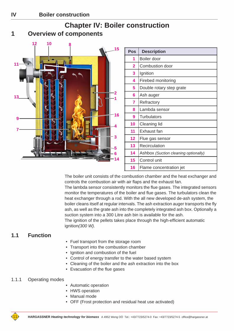
Chapter IV: Boiler construction1 Overview of components
The boiler unit consists of the combustion chamber and the heat exchanger and controls the combustion air with air flaps and the exhaust fan.The lambda sensor consistently monitors the flue gases. The integrated sensors monitor the temperatures of the boiler and flue gases. The turbulators clean the heat exchanger through a rod. With the all new developed de-ash system, the boiler cleans itself at regular intervals. The ash extraction auger transports the fly ash, as well as the grate ash into the completely integrated ash box. Optionally a suction system into a 300 Litre ash bin is available for the ash.The ignition of the pellets takes place through the high-efficient automatic ignition(300 W).
1.1 Function• Fuel transport from the storage room• Transport into the combustion chamber• Ignition and combustion of the fuel• Control of energy transfer to the water based system• Cleaning of the boiler and the ash extraction into the box• Evacuation of the flue gases
1.1.1 Operating modes• Automatic operation• HWS operation• Manual mode• OFF (Frost protection and residual heat use activated)
Pos Description1 Boiler door
2 Combustion door
3 Ignition
4 Firebed monitoring
5 Double rotary step grate
6 Ash auger
7 Refractory
8 Lambda sensor
9 Turbulators
10 Cleaning lid
11 Exhaust fan
12 Flue gas sensor
13 Recirculation
14 Ashbox (Suction cleaning optionally)
15 Control unit
16 Flame concentration jet
15
21
16
4
3
5614
11
13
9
7
81012
IV
VControlV
Chapter V: Control
1 Layout of the controlThe categorisation of the control is divided in:
• Display of current information about the boiler system Menu see “Standard menu” on page 13. Menu see “Menu tree - Info” on page 17.
• Settings through the customer Menu see “Customer settings” on page 21.
• Settings through the installer at commissioning Menu see “Installer level” on page 49.
• Settings through Hargassner service staff only Menu see “Parameter list - Customer” on page 55.
1.1 Touch- Screen, control unitThe control unit is executed through a Touch screen Handling through finger pressure on the display.
Scrolling in the menu through
For a better understanding the menu commands are placed within the <arrows>
Back to the previous menu with <Standard>
Back to the standard menu - at any time with <Standard>. <Standard>. (eventually press 2 times)
Activate the desired operation mode with selector switch <Func-tion>.
Activate input field through pressing. Display of values in "red" colour
Change the active values: Values flash "red" Buttons flash "green"
Enter, save or change of a value through with (SAVE).
Short cuts to customer parameters through pressing to the according graphic in the standard menu. possible at: Boiler-, Accumulator-, HWS-, External boiler and heating cir-
cuit - graphics
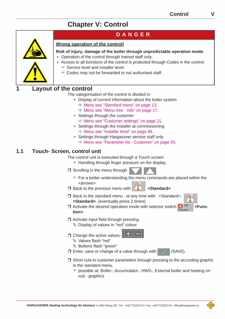
D A N G E R
Wrong operation of the control!Risk of injury, damage of the boiler through unpredictable operation mode.• Operation of the control through trained staff only. • Access to all functions of the control is protected through Codes in the control. Service level and installer level. Codes may not be forwarded to not authorised staff.
Function
Off
HARGASSNER Heating technology for biomass A 4952 Weng OÖ Tel.: +43/7723/5274-0 Fax: +43/7723/5274-5 [email protected] 12
V Control
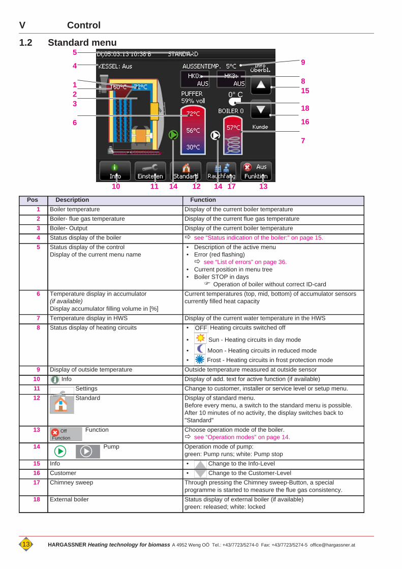
1.2 Standard menu
Pos Description Function1 Boiler temperature Display of the current boiler temperature2 Boiler- flue gas temperature Display of the current flue gas temperature3 Boiler- Output Display of the current boiler temperature4 Status display of the boiler see “Status indication of the boiler:” on page 15.5 Status display of the control
Display of the current menu name• Description of the active menu• Error (red flashing) see “List of errors” on page 36.
• Current position in menu tree• Boiler STOP in days
Operation of boiler without correct ID-card6 Temperature display in accumulator
(if available)Display accumulator filling volume in [%]
Current temperatures (top, mid, bottom) of accumulator sensorscurrently filled heat capacity
7 Temperature display in HWS Display of the current water temperature in the HWS8 Status display of heating circuits • Heating circuits switched off
• Sun - Heating circuits in day mode
• Moon - Heating circuits in reduced mode• Frost - Heating circuits in frost protection mode
9 Display of outside temperature Outside temperature measured at outside sensor10 Info Display of add. text for active function (if available)11 Settings Change to customer, installer or service level or setup menu.12 Standard Display of standard menu.
Before every menu, a switch to the standard menu is possible.After 10 minutes of no activity, the display switches back to "Standard"
13 Function Choose operation mode of the boiler. see “Operation modes” on page 14.
14 Pump Operation mode of pump:green: Pump runs; white: Pump stop
15 Info • Change to the Info-Level16 Customer • Change to the Customer-Level17 Chimney sweep Through pressing the Chimney sweep-Button, a special
programme is started to measure the flue gas consistency.18 External boiler Status display of external boiler (if available)
green: released; white: locked
9
815
18
16
7
5
4
123
6
10 11 14 12 14 1317
0° C
OFF
FunctionOff
13 HARGASSNER Heating technology for biomass A 4952 Weng OÖ Tel.: +43/7723/5274-0 Fax: +43/7723/5274-5 [email protected]
VControl
2 Operation modesChoose operation mode of the boiler
Press <Function>
2.1 Automatic • <Auto> (for Winteroperation for heating and domestic hot water) Control: Boiler, Accumulator, Heating circuits, HWS additional control of the heating circuits with remote control see “Optional remote controls FR35 / FR40 (digital)
and FR25 (analogue)” on page 26.
2.2 HWS operation• <HWS> (for summer operation - domestic hot water only) Control: Boiler, Accumulator, HWS Heating circuits
Heat circuit pumps off, mixing valve position "Closed"
2.3 Manual • <Manual>• to test single functions of the boiler separately (Motors, pumps, etc.) Boiler control switched off HWS pump off Heating circuits:
Heat circuit pumps off, mixing valve position "Closed" all automatic boiler functions are "OFF"
2.4 Off • <Off> Control: Boiler OFF Frost protection function activated HWS pump off Heating circuits:
Heat circuit pumps off, mixing valve position "Closed"
2.5 Chimney sweep - buttonButton for the chimney sweep to manually switch the boiler ON or OFF during emission tests.If an accumulator is connected, the control automatically changes to 100% combustionif the chimney sweep button is pressed.All programmed control functions of the boiler are switched off by pressing this button. The boiler operates at 100% heating output, assumes very low outside temperatures and tries to transports as much as possible heat into the heating system. All regulating devices like thermostatic head valves and automatic control valves must manually be opened to ensure the appropriate heat transfer. This function ends after 2 hours automatically.If the chimney sweep button is pressed and no accumulator is connected the control offers 2 possibilities: Full load measurement or Part load measurement.All programmed control functions of the boiler are switched off in part load measurement. The boiler controls up to 100% combustion. After 15 min. full load - the heat output is reduced to 50%. After 5 min. a message is shown on the display "Start measuring".
Function
Off
Function
Auto
Function
HWS
Function
Manu
HARGASSNER Heating technology for biomass A 4952 Weng OÖ Tel.: +43/7723/5274-0 Fax: +43/7723/5274-5 [email protected] 14

V Control
3 Status indication of the boiler:Because of the measured temperatures of the boiler and the flue gas temperature, the boiler control recognises the status of the boiler fully automatically.
„Boiler Off“:if no heat requirement from heat circuits or the HWS is notified, or the accumulator takes care of the demand, the boiler switches to "Off".
„Start ignition“:
Fuel is being transported into the combustion chamber and the boiler monitors, ifan autonomous ignition is possible due to remaining ember.
„Boiler Ignition“:
The electric ignition starts and the fuel if ignited.
„Boiler combustion“:Depending on heat demand and required boiler temperature the exhaust fan (air volume) and the Lambda sensor controls the optimum fuel amount Combustion output range from 50 - 100 [%]
„Boiler burnout“: Primary air to 100 % Exhaust fanoutput to 100 %
"Slumber mode":
if the heat demand drops below the minimum boiler output, the status changes temporary to "Slumber mode"
15 HARGASSNER Heating technology for biomass A 4952 Weng OÖ Tel.: +43/7723/5274-0 Fax: +43/7723/5274-5 [email protected]
VControl
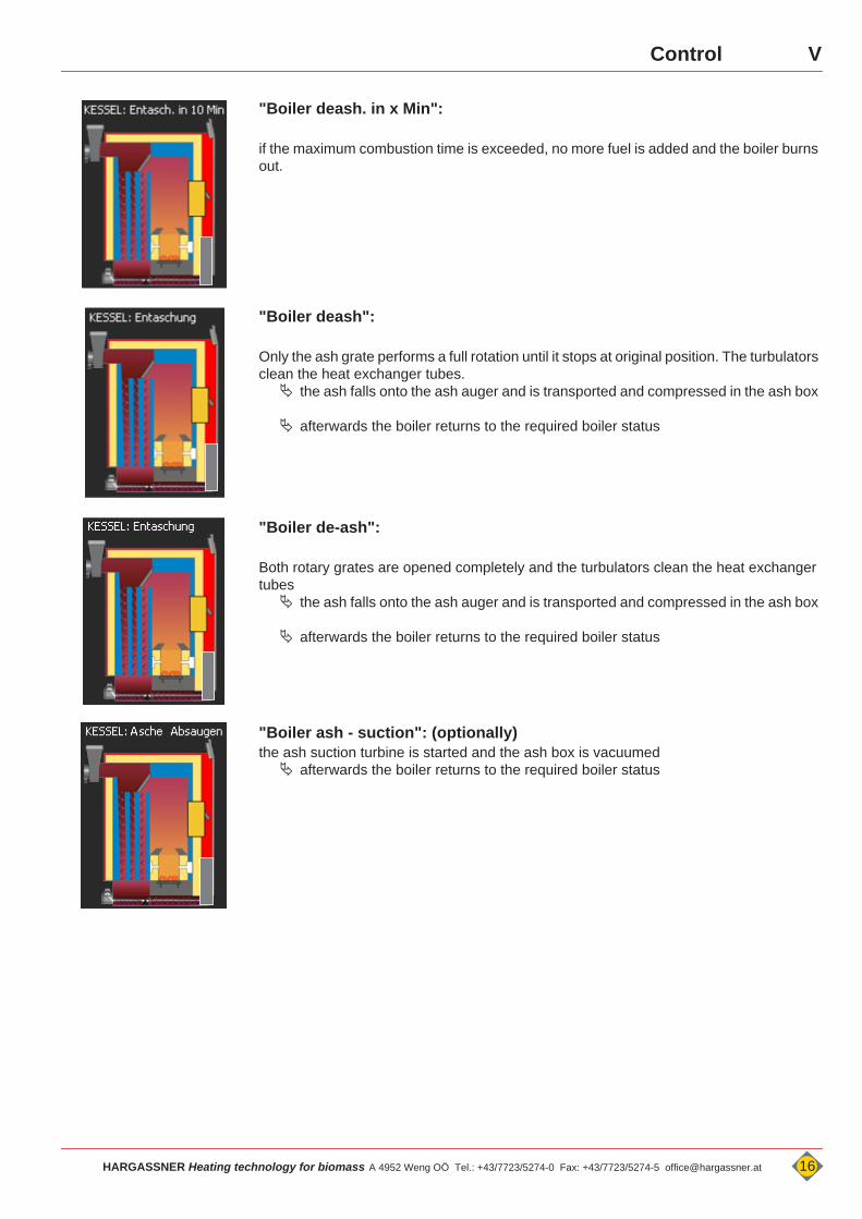
"Boiler deash. in x Min":
if the maximum combustion time is exceeded, no more fuel is added and the boiler burns out.
"Boiler deash":
Only the ash grate performs a full rotation until it stops at original position. The turbulators clean the heat exchanger tubes. the ash falls onto the ash auger and is transported and compressed in the ash box
afterwards the boiler returns to the required boiler status
"Boiler de-ash":
Both rotary grates are opened completely and the turbulators clean the heat exchanger tubes the ash falls onto the ash auger and is transported and compressed in the ash box
afterwards the boiler returns to the required boiler status
"Boiler ash - suction": (optionally)the ash suction turbine is started and the ash box is vacuumed afterwards the boiler returns to the required boiler status
HARGASSNER Heating technology for biomass A 4952 Weng OÖ Tel.: +43/7723/5274-0 Fax: +43/7723/5274-5 [email protected] 16
V Control
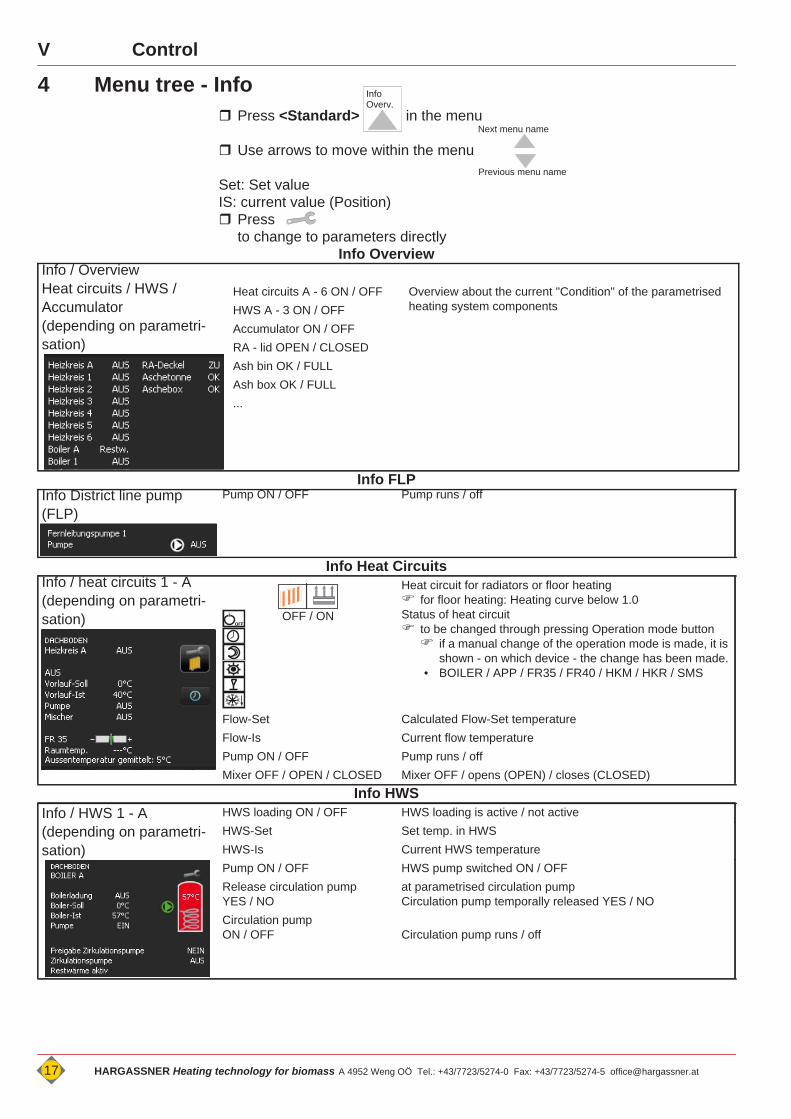
4 Menu tree - Info Press <Standard> in the menu
Use arrows to move within the menu
Set: Set valueIS: current value (Position) Press
to change to parameters directlyInfo Overview
Info FLP
Info Heat Circuits
Info HWS
Info Overv.
Next menu name
Previous menu name
Info / Overview Heat circuits / HWS / Accumulator(depending on parametri-sation)
Heat circuits A - 6 ON / OFF Overview about the current "Condition" of the parametrised heating system componentsHWS A - 3 ON / OFF
Accumulator ON / OFFRA - lid OPEN / CLOSEDAsh bin OK / FULLAsh box OK / FULL...
Info District line pump (FLP)
Pump ON / OFF Pump runs / off
Info / heat circuits 1 - A(depending on parametri-sation)
Heat circuit for radiators or floor heating for floor heating: Heating curve below 1.0Status of heat circuit to be changed through pressing Operation mode button if a manual change of the operation mode is made, it is
shown - on which device - the change has been made.• BOILER / APP / FR35 / FR40 / HKM / HKR / SMS
Flow-Set Calculated Flow-Set temperatureFlow-Is Current flow temperaturePump ON / OFF Pump runs / offMixer OFF / OPEN / CLOSED Mixer OFF / opens (OPEN) / closes (CLOSED)
Info / HWS 1 - A(depending on parametri-sation)
HWS loading ON / OFF HWS loading is active / not activeHWS-Set Set temp. in HWSHWS-Is Current HWS temperaturePump ON / OFF HWS pump switched ON / OFFRelease circulation pumpYES / NO
at parametrised circulation pumpCirculation pump temporally released YES / NO
Circulation pumpON / OFF Circulation pump runs / off
OFF / ONOFF
17 HARGASSNER Heating technology for biomass A 4952 Weng OÖ Tel.: +43/7723/5274-0 Fax: +43/7723/5274-5 [email protected]
VControl
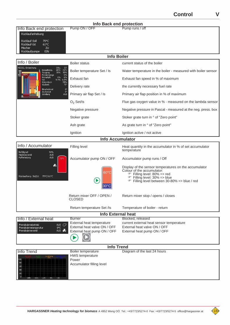
Info Back end protectionInfo Boiler
Info Accumulator
Info External heat
Info Trend
Info Back end protection Pump ON / OFF Pump runs / off
Info / Boiler Boiler status current status of the boiler
Boiler temperature Set / Is Water temperature in the boiler - measured with boiler sensor
Exhaust fan Exhaust fan speed in % of maximum
Delivery rate the currently necessary fuel rate
Primary air flap Set / Is Primary air flap position in % of maximum
O2 Set/Is Flue gas oxygen value in % - measured on the lambda sensor
Negative pressure Negative pressure in Pascal - measured at the neg. press. box
Stoker grate Stoker grate turn in ° of "Zero point"
Ash grate As grate turn in ° of "Zero point"
Ignition Ignition active / not active
Info / Accumulator Filling level Heat quantity in the accumulator in % of set accumulator temperature
Accumulator pump ON / OFF Accumulator pump runs / Off
Display of the sensor temperatures on the accumulatorColour of the accumulator: Filling level: 80% => red Filling level: 30% => blue Filling level between 30-80% => blue / red
Return mixer OFF / OPEN / CLOSED
Return mixer stop / opens / closes
Return temperature Set /Is Temperature of boiler - return
Info / External heat BurnerExternal heat temperatureExternal heat valve ON / OFFExternal heat pump ON / OFF
Blocked, releasedcurrent external heat sensor temperatureExternal heat valve ON / OFFExternal heat pump ON / OFF
Info Trend Boiler temperatureHWS temperaturePowerAccumulator filling level
Diagram of the last 24 hours
60°C
30°C
HARGASSNER Heating technology for biomass A 4952 Weng OÖ Tel.: +43/7723/5274-0 Fax: +43/7723/5274-5 [email protected] 18
V Control
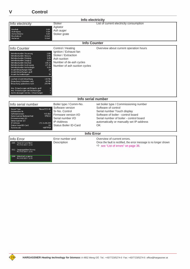
Info electricityInfo Counter
Info serial number
Info Error
Info electricity StokerAgitatorAsh augerStoker grate
List of current electricity consumption
Info Counter Control / HeatingIgnition / Exhaust fanStoker / ExtractionAsh suctionNumber of de-ash cyclesNumber of ash suction cycles
Overview about current operation hours
Info serial number Boiler type / Comm-No.Software versionSr-No. ControlFirmware version I/OSerial number I/OIP-AddressStatus Boiler ID-Card
set boiler type / Commissioning numberSoftware of controlSerial number Touch displaySoftware of boiler - control boardSerial number of boiler - control boardautomatically or manually set IP-addressOK
Info Error Error number and Description
Overview of current errors.Once the fault is rectified, the error message is no longer shown see “List of errors” on page 36.
19 HARGASSNER Heating technology for biomass A 4952 Weng OÖ Tel.: +43/7723/5274-0 Fax: +43/7723/5274-5 [email protected]
VControl
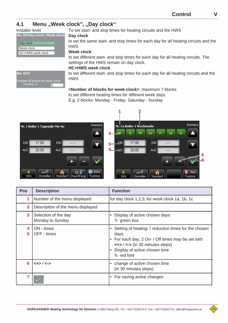
4.1 Menu „Week clock", „Day clock“Installer level To set start- and stop times for heating circuits and the HWS
Day clockto set the same start- and stop times for each day for all heating circuits and the HWSWeek clockto set different start- and stop times for each day for all heating circuits. The settings of the HWS remain on day clock.HC+HWS week clockto set different start- and stop times for each day for all heating circuits and the HWS
<Number of blocks for week clock>: maximum 7 blocksto set different heating times for different week days.E.g. 2 blocks: Monday - Friday, Saturday - Sunday
Day clock
No. D9 Day clock / Week clock
Week clockHC+HWS week clock
2
No. D10
Number of blocks for week clockFactory: 2
Pos Description Function
1 Number of the menu displayed for day clock 1,2,3; for week clock 1a, 1b, 1c
2 Description of the menu displayed
3 Selection of the dayMonday to Sunday
• Display of active chosen days green box
45
ON - timesOFF - times
• Setting of heating- / reduction times for the chosen days
• For each day, 2 On- / Off times may be set with <+> / <-> (in 30 minutes steps)
• Display of active chosen time red font
6 <+> / <-> • change of active chosen time (in 30 minutes steps)
7 • For saving active changes
68
4
56
1 2
HARGASSNER Heating technology for biomass A 4952 Weng OÖ Tel.: +43/7723/5274-0 Fax: +43/7723/5274-5 [email protected] 20
V Control
Control V
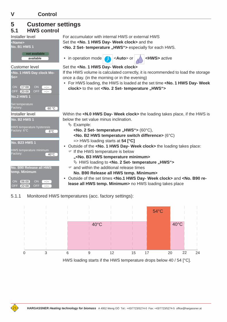
5 Customer settings5.1 HWS controlInstaller level For accumulator with internal HWS or external HWS
Set the <No. 1 HWS Day- Week clock> and the <No. 2 Set- temperature „HWS“> especially for each HWS.
• in operation mode <Auto> or <HWS> active
Customer level Set the <No. 1 HWS Day- Week clock>If the HWS volume is calculated correctly, it is recommended to load the storage once a day. (in the morning or in the evening)• For HWS loading, the HWS is loaded at the set time <No. 1 HWS Day- Week
clock> to the set <No. 2 Set- temperature „HWS“>
Installer level Within the <N.0 HWS Day- Week clock> the loading takes place, if the HWS is below the set value minus inclination. Example:
<No. 2 Set- temperature „HWS“> (60°C),<No. B2 HWS temperature switch difference> (6°C) => HWS loading starts at 54 [°C]
• Outside of the <No. 1 HWS Day- Week clock> the loading takes place: If the HWS temperature is below
„<No. B3 HWS temperature minimum> HWS loading to <No. 2 Set- temperature „HWS“>
and within the additional release times No. B90 Release all HWS temp. Minimum>
• Outside of the set times <No.1 HWS Day- Week clock> and <No. B90 re-lease all HWS temp. Minimum> no HWS loading takes place
5.1.1 Monitored HWS temperatures (acc. factory settings):
HWS loading starts if the HWS temperature drops below 40 / 54 [°C].
not available
<Name>No. B1 HWS 1
available
17:00
<No. 1 HWS Day clock Mo-So>
ONOFF 20:00
--:--ONOFF --:--
60 °C
No.2 HWS 1
Set temperatureFactory:
6°C
No. B2 HWS 1
HWS temperature hysteresisFactory: 6°C
40°C
No. B23 HWS 1
HWS temperature minimumFactory:
06:00
No. B90 Release all HWS temp. Minimum
ONOFF 22:00
--:--ONOFF --:--
0 6 9 12 15 243 17 20
40°C 40°C
54°C
22
21 HARGASSNER Heating technology for biomass A 4952 Weng OÖ Tel.: +43/7723/5274-0 Fax: +43/7723/5274-5 [email protected]
VControl
5.2 Circulation pump for hot waterCustomer level The circulation pump pumps hot water in cycles from the HWS to the consumer,
to immediately provide hot water if long distances have to overcome. Settings for the circulation pump may be performed for each HWS parametrised in the control. Release times for the circulation pump Defines the starting times of the circulation pump
Parametrisation of the circulation pump see “Parameter B - HWS:” on page 51.
5.3 Legionella programme
Installer level The legionella protection programme starts if Legionella protection - ON> especially for each activated HWS.
• The legionella protection programme heats up the HWS at the set time <No. B6 Legionella protection Weekly clock> to the set temperature <No. B5 Le-gionella protection Set- Temperature „HWS“>. Activation of the programme - up to 4 times a day
No.2a Circulation pump HWS 1
06:00ON 11:0008:00OFF 13:00
ONOFF
16:0020:00
ONOFF
D A N G E R
Temperature settings for Legionella protectionIf HWS temperature is not mixed and set very high - Risk of burning because of hot water!If HWS temperature is set too low - Legionella bacteria will not be entirely removed! • Set temperature to 70 [°C]. With a temperature of 70 [°C] for 3 minutes - all bacteria will be killed.
• Risk of burning - if HWS-circuit is not mixed - install mixing valve.• Siehe Montageanleitung “Brauchwassermischer”
OFF
No. B4 Legionella protection
ON
71 °C
No.B5 HWS 1
Legionella prot. Set temperatureFactory:
No.B6 Legionella protectionWeekly clockMo Tu We Th Fr Sa Su
17:00a --:--b--:--c --:--d
N O T E
Recommended settings for the legionella protection pro-gramme• Start of the protection programme within the time
<No. 1 HWS Day- Week clock>• Private family home: 1 x weekly• Gastronomy, hotels, etc...daily activation of legionella protection
programme (subject to local regulations)
HARGASSNER Heating technology for biomass A 4952 Weng OÖ Tel.: +43/7723/5274-0 Fax: +43/7723/5274-5 [email protected] 22
V Control
5.4 Control of heat circuits• activated in mode <Auto> for the heat circuits (1-6 and A), parametrised
by the installer.
5.4.1 Temperature controlThe control of the heating circuits works with:• „Heating“ to the set room temperature• „Reduction“ to the reduced room temperature• „Off“ - no room temperature control• „Frost protection“ (only pumps are on)
The control calculates the average outside temperature.Adjustment of set value settings for the room temperature(Day-reduction temperatures):
• only in small steps that a thermal state of inertia of the changed temperature can be
reached. The changed indoor climate will be recognised the next day.
Remote control:A slightly change of the set room temperature <No. 4 Day room temperature> of +/- 3 [°C] can be made directly on the remote control. see “Optional remote controls FR35 / FR40 (digital) and FR25 (analogue)” on
page 26.
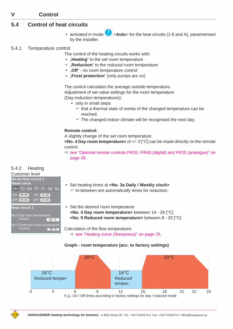
5.4.2 HeatingCustomer level
• Set heating times at <No. 3a Daily / Weekly clock> In-between are automatically times for reduction.
• Set the desired room temperature <No. 4 Day room temperature> between 14 - 26 [°C]<No. 5 Reduced room temperature> between 8 - 20 [°C]
Calculation of the flow temperature: see “Heating curve (Steepness)” on page 25.
Graph - room temperature (acc. to factory settings)
E.g.: On / Off times according to factory settings for day / reduced mode
No.3a Heat circuit 1Week clock Mo Tu We Th Fr Sa Su
06:00ON 15:0009:00 22:00
ONOFF OFF
20 °C
Heat circuit 1
No.4 Day room temperature:Factory:
16 °CNo.5 Reduction room temperature:
Factory:
0 6 9 12 15 243 18 21
16°C
22
16°CReduced temper-
20°C 20°C
Reduced temper-
23 HARGASSNER Heating technology for biomass A 4952 Weng OÖ Tel.: +43/7723/5274-0 Fax: +43/7723/5274-5 [email protected]
VControl
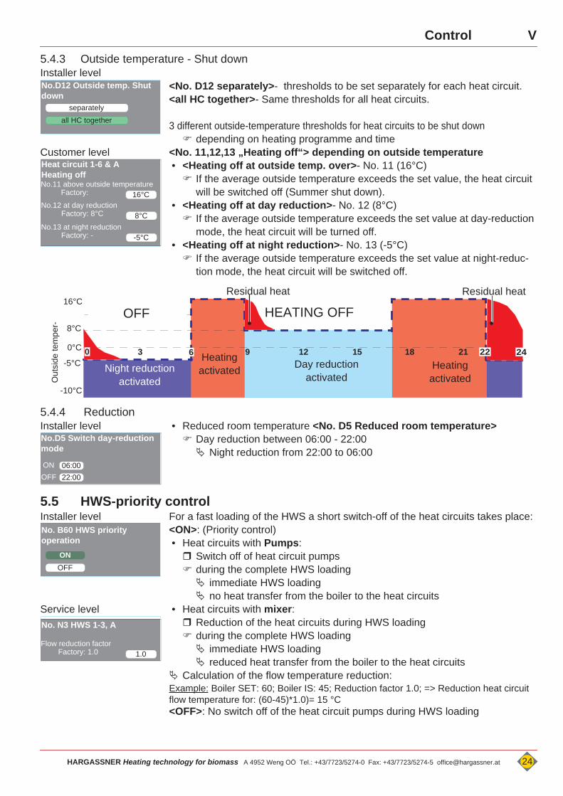
5.4.3 Outside temperature - Shut downInstaller level<No. D12 separately>- thresholds to be set separately for each heat circuit.<all HC together>- Same thresholds for all heat circuits.
3 different outside-temperature thresholds for heat circuits to be shut down depending on heating programme and time
Customer level <No. 11,12,13 „Heating off“> depending on outside temperature• <Heating off at outside temp. over>- No. 11 (16°C) If the average outside temperature exceeds the set value, the heat circuit
will be switched off (Summer shut down).• <Heating off at day reduction>- No. 12 (8°C) If the average outside temperature exceeds the set value at day-reduction
mode, the heat circuit will be turned off.• <Heating off at night reduction>- No. 13 (-5°C) If the average outside temperature exceeds the set value at night-reduc-
tion mode, the heat circuit will be switched off.
5.4.4 ReductionInstaller level • Reduced room temperature <No. D5 Reduced room temperature>
Day reduction between 06:00 - 22:00 Night reduction from 22:00 to 06:00
5.5 HWS-priority controlInstaller level For a fast loading of the HWS a short switch-off of the heat circuits takes place:
<ON>: (Priority control)• Heat circuits with Pumps: Switch off of heat circuit pumps during the complete HWS loading immediate HWS loading no heat transfer from the boiler to the heat circuits
Service level • Heat circuits with mixer: Reduction of the heat circuits during HWS loading during the complete HWS loading immediate HWS loading reduced heat transfer from the boiler to the heat circuits
Calculation of the flow temperature reduction:Example: Boiler SET: 60; Boiler IS: 45; Reduction factor 1.0; => Reduction heat circuit flow temperature for: (60-45)*1.0)= 15 °C<OFF>: No switch off of the heat circuit pumps during HWS loading
separately
No.D12 Outside temp. Shut down
all HC together
16°C
Heat circuit 1-6 & A Heating offNo.11 above outside temperature
Factory:
8°CNo.12 at day reduction
Factory: 8°C
-5°CNo.13 at night reduction
Factory: -
243 18 21
16°C
Night reductionactivatedO
utsi
de te
mpe
r-
-5°C
-10°C
8°C
0°C
HEATING OFF
9 12 15Heating activated Day reduction
activated
OFF
Residual heat Residual heat
2260 24Heating
activated
No.D5 Switch day-reduction mode
06:00ON22:00OFF
ON
No. B60 HWS priority operation
OFF
1.0
No. N3 HWS 1-3, A
Flow reduction factorFactory: 1.0
HARGASSNER Heating technology for biomass A 4952 Weng OÖ Tel.: +43/7723/5274-0 Fax: +43/7723/5274-5 [email protected] 24
V Control
5.6 Frost protectionInstaller level Two safety steps to activate the frost protection function
• Outside temperature below parameter <No. D2 Frost prot. > (1°C) Start up of heat circuit pumps, Mixers remain „Closed“
• Boiler- or flow temperature below parameter <No. D3 Frost protection> (7°C) Start up of the boiler and mixing valve control activated
5.7 Accumulator control see “Parameter C - Accumulator” on page 52.
5.8 Blockage protectionTo prevent any blockage of pumps or mixing valves after a long period of stand-still, the devices starts automatically.
• Every Monday at 12:00 a.m.• Start heat circuit pumps (1 Minute)• Mixing valves open and close once
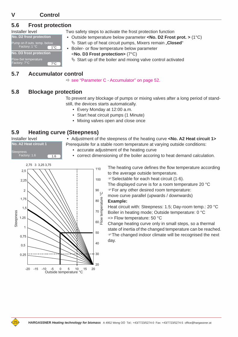
5.9 Heating curve (Steepness)Installer level • Adjustment of the steepness of the heating curve <No. A2 Heat circuit 1>
Prerequisite for a stable room temperature at varying outside conditions:• accurate adjustment of the heating curve• correct dimensioning of the boiler accoring to heat demand calculation.
The heating curve defines the flow temperature according to the average outside temperature. Selectable for each heat circuit (1-6).The displayed curve is for a room temperature 20 °CFor any other desired room temperature:move curve parallel (upwards / downwards)Example:Heat circuit with: Steepness: 1.5; Day-room temp.: 20 °CBoiler in heating mode; Outside temperature: 0 °C=> Flow temperature: 50 °CChange heating curve only in small steps, so a thermal state of inertia of the changed temperature can be reached.The changed indoor climate will be recognised the next day.
1°C
No. D2 frost protectionPump on if outs. temp. below
Factory: 1 °C
7°C
No. D3 frost protectionFlow-Set temperatureFactory: 7°C
1.6
No. A2 Heat circuit 1
SteepnessFactory: 1.6
20
30
40
50
60
70
80
90
100
110
02- 51- 01- 5- 0 5 01 51 02
f°C
2,5
2,25
2
1,75
1,5
1,25
1
0,75
0,5
0,25
2,75 3 3,25 3,75
Outside temperature °C
Ste
epne
ss
Flow
tem
pera
ture
°C
25 HARGASSNER Heating technology for biomass A 4952 Weng OÖ Tel.: +43/7723/5274-0 Fax: +43/7723/5274-5 [email protected]
VControl
6 Optional remote controls FR35 / FR40 (digital) and FR25 (analogue)
One heat circuit may be parametrised per remote control.• one heat circuit or extension control board (HKA digital remote controls only)• 2 heat circuits per extension module (HKM 0 - 2) • 2 heat circuits per heat circuit controller (HKR 1 - 8)
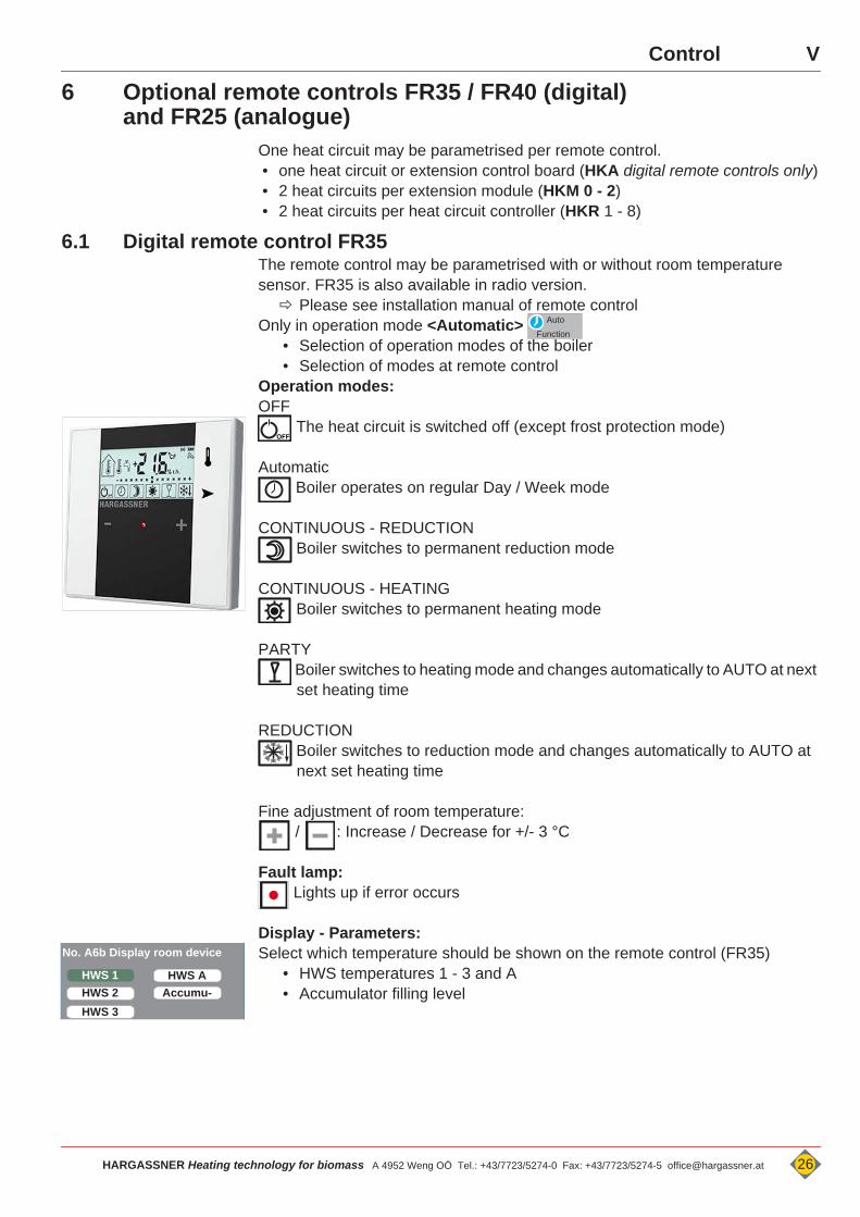
6.1 Digital remote control FR35The remote control may be parametrised with or without room temperature sensor. FR35 is also available in radio version. Please see installation manual of remote control
Only in operation mode <Automatic> • Selection of operation modes of the boiler• Selection of modes at remote control
Operation modes: OFF
The heat circuit is switched off (except frost protection mode)
Automatic Boiler operates on regular Day / Week mode
CONTINUOUS - REDUCTION Boiler switches to permanent reduction mode
CONTINUOUS - HEATING Boiler switches to permanent heating mode
PARTY Boiler switches to heating mode and changes automatically to AUTO at next set heating time
REDUCTION Boiler switches to reduction mode and changes automatically to AUTO at next set heating time
Fine adjustment of room temperature: / : Increase / Decrease for +/- 3 °C
Fault lamp: Lights up if error occurs
Display - Parameters:Select which temperature should be shown on the remote control (FR35)
• HWS temperatures 1 - 3 and A• Accumulator filling level
FunctionAuto
OFF
No. A6b Display room device
HWS 1HWS 2HWS 3
HWS AAccumu-
HARGASSNER Heating technology for biomass A 4952 Weng OÖ Tel.: +43/7723/5274-0 Fax: +43/7723/5274-5 [email protected] 26
V Control
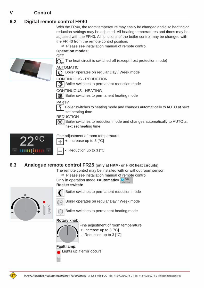
6.2 Digital remote control FR40With the FR40, the room temperature may easily be changed and also heating or reduction settings may be adjusted. All heating temperatures and times may be adjusted with the FR40. All functions of the boiler control may be changed with the FR 40 from the remote control position. Please see installation manual of remote control
Operation modes: OFF
The heat circuit is switched off (except frost protection mode)
AUTOMATIC Boiler operates on regular Day / Week mode
CONTINUOUS - REDUCTION Boiler switches to permanent reduction mode
CONTINUOUS - HEATING Boiler switches to permanent heating mode
PARTY Boiler switches to heating mode and changes automatically to AUTO at next set heating time
REDUCTION Boiler switches to reduction mode and changes automatically to AUTO at next set heating time
Fine adjustment of room temperature: +: Increase up to 3 [°C]
-: Reduction up to 3 [°C]
6.3 Analogue remote control FR25 (only at HKM- or HKR heat circuits)The remote control may be installed with or without room sensor. Please see installation manual of remote control
Only in operation mode <Automatic> Rocker switch:
Boiler switches to permanent reduction mode
Boiler operates on regular Day / Week mode
Boiler switches to permanent heating mode
Rotary knob: Fine adjustment of room temperature:+: Increase up to 3 [°C] -: Reduction up to 3 [°C]
Fault lamp: Lights up if error occurs
OFF
FunctionAuto
0
0
27 HARGASSNER Heating technology for biomass A 4952 Weng OÖ Tel.: +43/7723/5274-0 Fax: +43/7723/5274-5 [email protected]
VI
HARGASSNER Heating technology for biomass A 4952 Weng OÖ Tel.: +43/7723/5274-0 Fax: +43/7723/5274-5 [email protected] 28
Commissioning
Chapter VI: Commissioning
1 Checks prior commissioning safety on-site and plumbing and electrical installations Siehe Montageanleitung “Einrichtungen bauseits” Boiler assembly Check all necessary components to correct assembly, correct function, correct rotation of all motors, etc. to correct placement of combustion chamber lining
2 Start of commissioningAfter professional installation and inspection of all necessary safety requirements the commissioning can be performed according to the enclosed commissioning check list.
2.1 Customer instructions Explain "Cleaning- and maintenance intervals" see “Cleaning intervals” on page 32.
Explain "Inspections prior any fuel refill" see “Inspections prior starting up the boiler” on page 30.
Explain "How to operate and troubleshooting" see “Rectify and clear errors” on page 35.
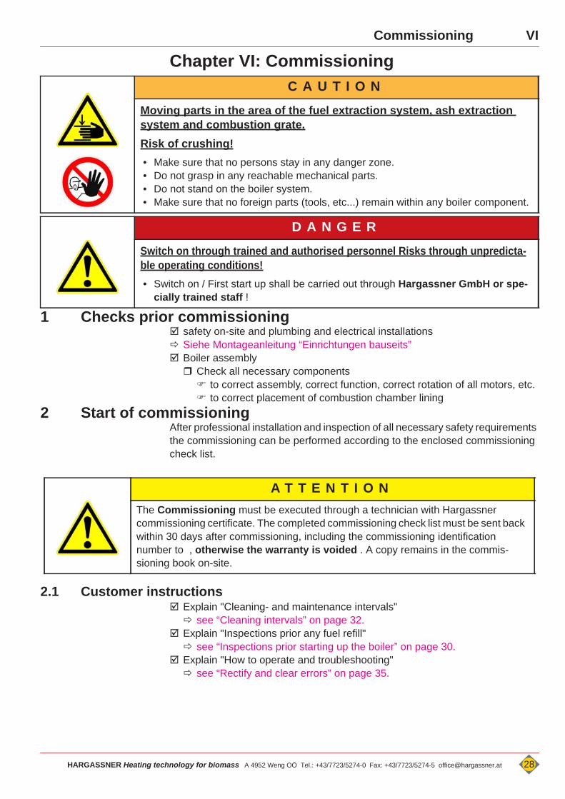
C A U T I O N
Moving parts in the area of the fuel extraction system, ash extraction system and combustion grate.Risk of crushing!• Make sure that no persons stay in any danger zone.• Do not grasp in any reachable mechanical parts.• Do not stand on the boiler system.• Make sure that no foreign parts (tools, etc...) remain within any boiler component.
D A N G E R
Switch on through trained and authorised personnel Risks through unpredicta-ble operating conditions!• Switch on / First start up shall be carried out through Hargassner GmbH or spe-
cially trained staff !
A T T E N T I O NThe Commissioning must be executed through a technician with Hargassner commissioning certificate. The completed commissioning check list must be sent back within 30 days after commissioning, including the commissioning identification number to , otherwise the warranty is voided . A copy remains in the commis-sioning book on-site.
VI
VII OperationVII
Chapter VII: Operation1 Safety instructions
1.1 Measures in case of danger1.1.1 Fire in the boiler room
Switch-off main switch prior any fire-fighting operations Disconnect main power supply Switch-off the boiler and unplug the unit from the mains
1.1.2 After power lossDo not open the boiler door or touch any parts of the boiler at/after power loss Danger of deflagration Danger of crushing through augers
After the electrical supply is switched on again, the control starts in "Heat up" mode and monitors the flue gas temperature. Flue gas temperature increases The boiler is in combustion mode and the control controls the heat
transfer according to set parameters
1.1.3 Leak in heating water system (no water)If insufficient water pressure occurs, there is also insufficient heat transfer from the boiler to the heat circuits, HWS and accumulator. Danger of boiler overheating Do not continue to heat up the boiler. Fix leakiness fill / refill water system Check water pressure
1.1.4 Check boiler for leakages (Smoke) Do not continue to heat up the boiler Check sealings of doors and maintenance openings and renew
1.1.5 Auger blockageDo not touch the augers Danger of crushing at sudden release of blockages
Press<Reverse> - Button of the blocked auger max. 2 seconds
Remove blockages and clean augers with tools only. Switch-off and lock<Main switch>
D A N G E R
Missing, defective or bridged safety devices and boiler parts!Death, injuries, damages caused by not correctly operating or missing safety devices or plant parts.
• Check safety devices and boiler components carefully for proper and intended func-tion.
• Safety devices should not be modified or bypassed.• In case of malfunction or defect, perform immediate repair measures. • Place, position and function of all safety devices must be known.
29 HARGASSNER Heating technology for biomass A 4952 Weng OÖ Tel.: +43/7723/5274-0 Fax: +43/7723/5274-5 [email protected]
VIIOperation
2 Start-up boiler for the first timeAfter finished commissioning the boiler may be started the first time. Please proceed as follows.
for first fill, only use a small amount of fuel, distribute it under the spring blades Install a "sloping floor" with fuel
switch to operation mode „AUTO“ or „HWS“ Boiler starts automatically if hot water is needed
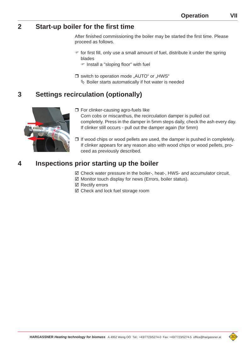
3 Settings recirculation (optionally)
For clinker-causing agro-fuels like Corn cobs or miscanthus, the recirculation damper is pulled out completely. Press in the damper in 5mm steps daily, check the ash every day. If clinker still occurs - pull out the damper again (for 5mm)
If wood chips or wood pellets are used, the damper is pushed in completely. If clinker appears for any reason also with wood chips or wood pellets, pro-ceed as previously described.
4 Inspections prior starting up the boiler Check water pressure in the boiler-, heat-, HWS- and accumulator circuit. Monitor touch display for news (Errors, boiler status). Rectify errors Check and lock fuel storage room
HARGASSNER Heating technology for biomass A 4952 Weng OÖ Tel.: +43/7723/5274-0 Fax: +43/7723/5274-5 [email protected] 30
VIII Cleaning, MaintenanceVIII
Kapitel VIII: Cleaning, Maintenance D A N G E R
Rotating augers and moving parts !Amputation, crushing of hands through touching moving parts or augers.• Omit access to augers or motors at operating boiler.• Fix ash box correctly on the boiler and lock.• Do not perform any works on the plant, if any other person is in the
danger zone.• Remove blockages and clean augers with tools only.
C A U T I O N
Moving parts in the fuel extraction system, hollow space formation in the fuel storage roomUnpredictable operation conditions• The spring blades of the agitator system are retracted under the
cover disc if the storage room is filled completely. These springs may shoot up suddenly.
• Remove fuel bridges with rods or shovels only• Wear safety shoes• Observe fuel storage room sticker!
D A N G E R
Disconnect main power supplyTouching open or free terminals, cables and equipment compo-nents can lead to severe injury or death! • Disconnect power supply prior any cleaning or maintenance works. Switch-off and lock<Main switch>
D A N G E R
After <Main switch off> or <OFF> - mode:Risk of injury due to grasping into a danger zone - Re-com-missioning!Crushing, amputation.• After actuation of the <Main switch off> or <OFF> switch, do not
grasp into any danger zone.• Prior any works on the boiler and its equipment, switch off the
<Main switch> and protect the main switch against resetting with a professional padlock. Hand out the key for a lock to the person in charge only.
• Rectify error.• Check at re-commissioning that no person is in any danger zone.
31 HARGASSNER Heating technology for biomass A 4952 Weng OÖ Tel.: +43/7723/5274-0 Fax: +43/7723/5274-5 [email protected]
VIIICleaning, Maintenance
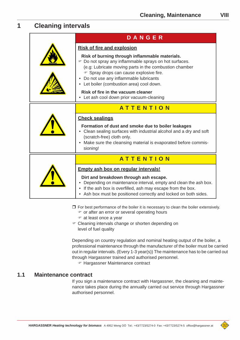
1 Cleaning intervals
For best performance of the boiler it is necessary to clean the boiler extensively. or after an error or several operating hours at least once a year
Cleaning intervals change or shorten depending on level of fuel quality
Depending on country regulation and nominal heating output of the boiler, a professional maintenance through the manufacturer of the boiler must be carried out in regular intervals. (Every 1-3 year(s)) The maintenance has to be carried out through Hargassner trained and authorised personnel. Hargassner Maintenance contract
1.1 Maintenance contractIf you sign a maintenance contract with Hargassner, the cleaning and mainte-nance takes place during the annually carried out service through Hargassner authorised personnel.
D A N G E R
Risk of fire and explosionRisk of burning through inflammable materials. Do not spray any inflammable sprays on hot surfaces.
(e.g: Lubricate moving parts in the combustion chamber Spray drops can cause explosive fire.
• Do not use any inflammable lubricants• Let boiler (combustion area) cool down.
Risk of fire in the vacuum cleaner• Let ash cool down prior vacuum-cleaning
A T T E N T I O N
Check sealingsFormation of dust and smoke due to boiler leakages
• Clean sealing surfaces with industrial alcohol and a dry and soft (scratch-free) cloth only.
• Make sure the cleansing material is evaporated before commis-sioning!
A T T E N T I O N
Empty ash box on regular intervals!Dirt and breakdown through ash escape.
• Depending on maintenance interval, empty and clean the ash box. • If the ash box is overfilled, ash may escape from the box.• Ash box must be positioned correctly and locked on both sides.
HARGASSNER Heating technology for biomass A 4952 Weng OÖ Tel.: +43/7723/5274-0 Fax: +43/7723/5274-5 [email protected] 32
VIII Cleaning, Maintenance
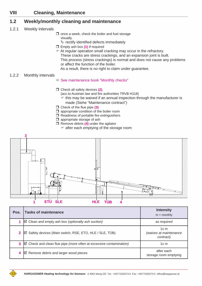
1.2 Weekly/monthly cleaning and maintenance1.2.1 Weekly intervals
once a week, check the boiler and fuel storage visually. rectify identified defects immediately
Empty ash box (1) if required At regular operation small cracking may occur in the refractory.
These cracks are stress crackings, and an expansion joint is built.This process (stress crackings) is normal and does not cause any problems or affect the function of the boiler.As a result, there is no right to claim under guarantee.
1.2.2 Monthly intervals See maintenance book "Monthly checks"
Check all safety devices (2).(acc.to Austrian law and fire authorities TRVB H118) this may be waived if an annual inspection through the manufacturer is
made (Siehe “Maintenance contract”) Check of the flue pipe (3) appropriate condition of the boiler room Readiness of portable fire extinguishers appropriate storage of ash Remove debris (4) under the agitator after each emptying of the storage room
Pos. Tasks of maintenance Intensitym = monthly
1 Clean and empty ash box (optionally ash suction) as required
2 Safety devices (Main switch, RSE, ETÜ, HLE / SLE, TÜB)1x m
(waives at maintenance contract)
3 Check and clean flue pipe (more often at excessive contamination) 1x m
4 Remove debris and larger wood pieces after eachstorage room emptying
1 4
3
TÜBSLE HLEETÜ
33 HARGASSNER Heating technology for biomass A 4952 Weng OÖ Tel.: +43/7723/5274-0 Fax: +43/7723/5274-5 [email protected]
VIIICleaning, Maintenance
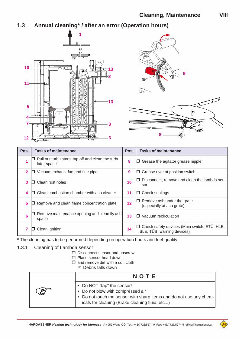
1.3 Annual cleaning* / after an error (Operation hours)
* The cleaning has to be performed depending on operation hours and fuel-quality.
1.3.1 Cleaning of Lambda sensor Disconnect sensor and unscrew Place sensor head down and remove dirt with a soft cloth Debris falls down
Pos. Tasks of maintenance Pos. Tasks of maintenance
1 Pull out turbulators, tap off and clean the turbu-lator space 8 Grease the agitator grease nipple
2 Vacuum exhaust fan and flue pipe 9 Grease rivet at position switch
3 Clean rust holes 10 Disconnect, remove and clean the lambda sen-sor
4 Clean combustion chamber with ash cleaner 11 Check sealings
5 Remove and clean flame concentration plate 12 Remove ash under the grate(especially at ash grate)
6 Remove maintenance opening and clean fly ash space 13 Vacuum recirculation
7 Clean ignition 14 Check safety devices (Main switch, ETÜ, HLE, SLE, TÜB, warning devices)
1
2
4
5
6
37
10
12
13
11
8
13
9
N O T E
• Do NOT "tap" the sensor!• Do not blow with compressed air• Do not touch the sensor with sharp items and do not use any chem-
icals for cleaning (Brake cleaning fluid, etc...)
HARGASSNER Heating technology for biomass A 4952 Weng OÖ Tel.: +43/7723/5274-0 Fax: +43/7723/5274-5 [email protected] 34

IX Troubleshooting
IX
Chapter IX: Troubleshooting
1 ErrorsError messages to be read on the touch display. on the Standard-Display a warning triangle appears at the position where the
error occurs (A)The following instructions to rectify errors are aimed for the direct user of this boiler. If it is not possible to rectify the error through the operator, the installer / Har-gassner must be informed.
1.1 Rectify and clear errorsAfter rectification of the error: Press
1.2 Retrieve error listIf error messages occur: Press <ERROR> (B) button Display of error list (latest errors)
A T T E N T I O N
Changes compared to regular operationInjuries, Damages of the boiler
• due to higher heating output, higher temperatures or vibrations of motors, unusual noises or smells, release of safety devices, etc.
• Immediately call the installer / Hargassner• Perform mandatory maintenance and inspection tasks regularly.
A B
17. April 10:35 Error list
0090 Boiler IO not connectedWe 17-06-2013 09:36
0087 Error exhaust fanATTENTION! Do not open doorsWe 17-06-2013 09:37
Settings StandardInfo Function
35 HARGASSNER Heating technology for biomass A 4952 Weng OÖ Tel.: +43/7723/5274-0 Fax: +43/7723/5274-5 [email protected]
IXTroubleshooting
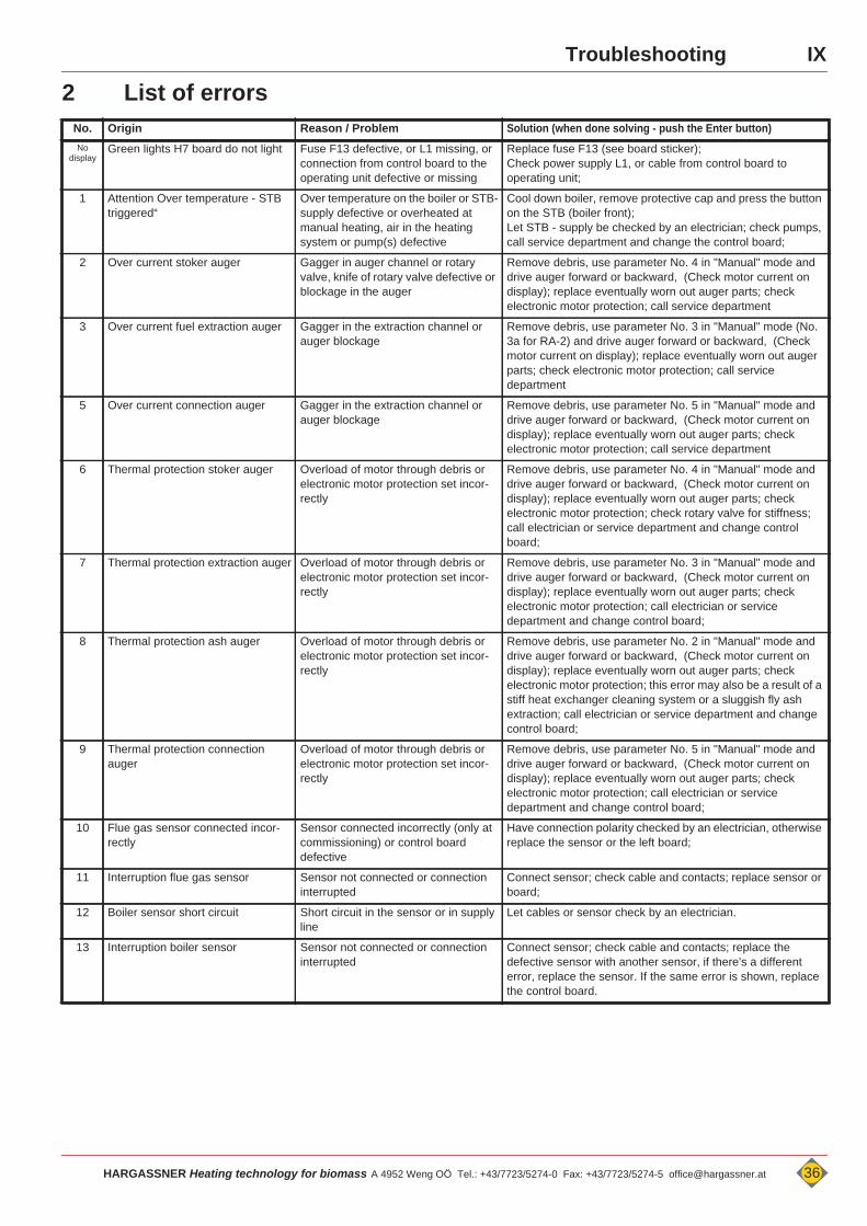
2 List of errorsNo. Origin Reason / Problem Solution (when done solving - push the Enter button)No
displayGreen lights H7 board do not light Fuse F13 defective, or L1 missing, or
connection from control board to the operating unit defective or missing
Replace fuse F13 (see board sticker); Check power supply L1, or cable from control board to operating unit;
1 Attention Over temperature - STB triggered“
Over temperature on the boiler or STB-supply defective or overheated at manual heating, air in the heating system or pump(s) defective
Cool down boiler, remove protective cap and press the button on the STB (boiler front); Let STB - supply be checked by an electrician; check pumps, call service department and change the control board;
2 Over current stoker auger Gagger in auger channel or rotary valve, knife of rotary valve defective or blockage in the auger
Remove debris, use parameter No. 4 in "Manual" mode and drive auger forward or backward, (Check motor current on display); replace eventually worn out auger parts; check electronic motor protection; call service department
3 Over current fuel extraction auger Gagger in the extraction channel or auger blockage
Remove debris, use parameter No. 3 in "Manual" mode (No. 3a for RA-2) and drive auger forward or backward, (Check motor current on display); replace eventually worn out auger parts; check electronic motor protection; call service department
5 Over current connection auger Gagger in the extraction channel or auger blockage
Remove debris, use parameter No. 5 in "Manual" mode and drive auger forward or backward, (Check motor current on display); replace eventually worn out auger parts; check electronic motor protection; call service department
6 Thermal protection stoker auger Overload of motor through debris or electronic motor protection set incor-rectly
Remove debris, use parameter No. 4 in "Manual" mode and drive auger forward or backward, (Check motor current on display); replace eventually worn out auger parts; check electronic motor protection; check rotary valve for stiffness; call electrician or service department and change control board;
7 Thermal protection extraction auger Overload of motor through debris or electronic motor protection set incor-rectly
Remove debris, use parameter No. 3 in "Manual" mode and drive auger forward or backward, (Check motor current on display); replace eventually worn out auger parts; check electronic motor protection; call electrician or service department and change control board;
8 Thermal protection ash auger Overload of motor through debris or electronic motor protection set incor-rectly
Remove debris, use parameter No. 2 in "Manual" mode and drive auger forward or backward, (Check motor current on display); replace eventually worn out auger parts; check electronic motor protection; this error may also be a result of a stiff heat exchanger cleaning system or a sluggish fly ash extraction; call electrician or service department and change control board;
9 Thermal protection connection auger
Overload of motor through debris or electronic motor protection set incor-rectly
Remove debris, use parameter No. 5 in "Manual" mode and drive auger forward or backward, (Check motor current on display); replace eventually worn out auger parts; check electronic motor protection; call electrician or service department and change control board;
10 Flue gas sensor connected incor-rectly
Sensor connected incorrectly (only at commissioning) or control board defective
Have connection polarity checked by an electrician, otherwise replace the sensor or the left board;
11 Interruption flue gas sensor Sensor not connected or connection interrupted
Connect sensor; check cable and contacts; replace sensor or board;
12 Boiler sensor short circuit Short circuit in the sensor or in supply line
Let cables or sensor check by an electrician.
13 Interruption boiler sensor Sensor not connected or connection interrupted
Connect sensor; check cable and contacts; replace the defective sensor with another sensor, if there's a different error, replace the sensor. If the same error is shown, replace the control board.
HARGASSNER Heating technology for biomass A 4952 Weng OÖ Tel.: +43/7723/5274-0 Fax: +43/7723/5274-5 [email protected] 36
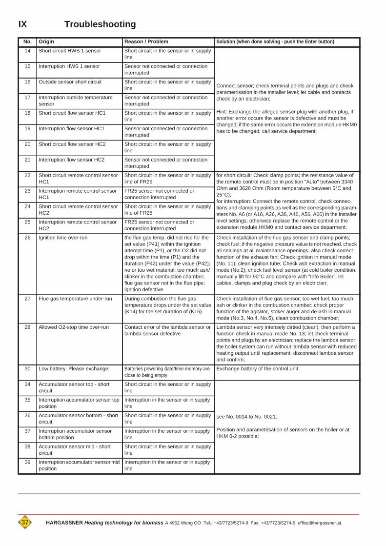
IX Troubleshooting
No. Origin Reason / Problem Solution (when done solving - push the Enter button)
14 Short circuit HWS 1 sensor Short circuit in the sensor or in supply line
Connect sensor; check terminal points and plugs and check parametrisation in the installer level; let cable and contacts check by an electrician;
Hint: Exchange the alleged sensor plug with another plug, if another error occurs the sensor is defective and must be changed; if the same error occurs the extension module HKM0 has to be changed; call service department;
15 Interruption HWS 1 sensor Sensor not connected or connection interrupted
16 Outside sensor short circuit Short circuit in the sensor or in supply line
17 Interruption outside temperature sensor
Sensor not connected or connection interrupted
18 Short circuit flow sensor HC1 Short circuit in the sensor or in supply line
19 Interruption flow sensor HC1 Sensor not connected or connection interrupted
20 Short circuit flow sensor HC2 Short circuit in the sensor or in supply line
21 Interruption flow sensor HC2 Sensor not connected or connection interrupted
22 Short circuit remote control sensor HC1
Short circuit in the sensor or in supply line of FR25
for short circuit: Check clamp points; the resistance value of the remote control must be in position "Auto" between 3340 Ohm and 3626 Ohm (Room temperature between 5°C and 25°C);for interruption: Connect the remote control, check connec-tions and clamping points as well as the corresponding param-eters No. A6 (or A16, A26, A36, A46, A56, A66) in the installer level settings; otherwise replace the remote control or the extension module HKM0 and contact service deparment;
23 Interruption remote control sensor HC1
FR25 sensor not connected or connection interrupted
24 Short circuit remote control sensor HC2
Short circuit in the sensor or in supply line of FR25
25 Interruption remote control sensor HC2
FR25 sensor not connected or connection interrupted
26 Ignition time over-run the flue gas temp. did not rise for the set value (P41) within the ignition attempt time (P1), or the O2 did not drop within the time (P1) and the duration (P43) under the value (P42); no or too wet material; too much ash/clinker in the combustion chamber; flue gas sensor not in the flue pipe; ignition defective
Check installation of the flue gas sensor and clamp points; check fuel; if the negative pressure value is not reached, check all sealings at all maintenance openings, also check correct function of the exhaust fan; Check ignition in manual mode (No. 11); clean ignition tube; Check ash extraction in manual mode (No.2); check fuel level sensor (at cold boiler condition, manually lift for 90°C and compare with "Info Boiler"; let cables, clamps and plug check by an electrician;
27 Flue gas temperature under-run During combustion the flue gas temperature drops under the set value (K14) for the set duration of (K15)
Check installation of flue gas sensor; too wet fuel; too much ash or clinker in the combustion chamber; check proper function of the agitator, stoker auger and de-ash in manual mode (No.3, No.4, No.5), clean combustion chamber;
28 Allowed O2-stop time over-run Contact error of the lambda sensor or lambda sensor defective
Lambda sensor very intensely dirtied (clean), then perform a function check in manual mode No. 13; let check terminal points and plugs by an electrician; replace the lambda sensor; the boiler system can run without lambda sensor with reduced heating output until replacement; disconnect lambda sensor and confirm;
30 Low battery. Please exchange! Batteries powering date/time memory are close to being empty
Exchange battery of the control unit
34 Accumulator sensor top - short circuit
Short circuit in the sensor or in supply line
see No. 0014 to No. 0021;
Position and parametrisation of sensors on the boiler or at HKM 0-2 possible;
35 Interruption accumulator sensor top position
Interruption in the sensor or in supply line
36 Accumulator sensor bottom - short circuit
Short circuit in the sensor or in supply line
37 Interruption accumulator sensor bottom position
Interruption in the sensor or in supply line
38 Accumulator sensor mid - short circuit
Short circuit in the sensor or in supply line
39 Interruption accumulator sensor mid position
Interruption in the sensor or in supply line
37 HARGASSNER Heating technology for biomass A 4952 Weng OÖ Tel.: +43/7723/5274-0 Fax: +43/7723/5274-5 [email protected]
IXTroubleshooting
No. Origin Reason / Problem Solution (when done solving - push the Enter button)
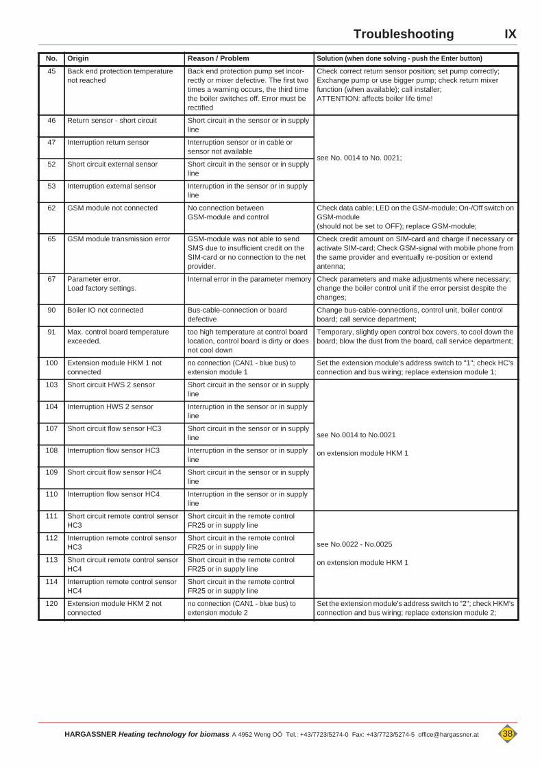
45 Back end protection temperature not reached
Back end protection pump set incor-rectly or mixer defective. The first two times a warning occurs, the third time the boiler switches off. Error must be rectified
Check correct return sensor position; set pump correctly; Exchange pump or use bigger pump; check return mixer function (when available); call installer;ATTENTION: affects boiler life time!
46 Return sensor - short circuit Short circuit in the sensor or in supply line
see No. 0014 to No. 0021;
47 Interruption return sensor Interruption sensor or in cable or sensor not available
52 Short circuit external sensor Short circuit in the sensor or in supply line
53 Interruption external sensor Interruption in the sensor or in supply line
62 GSM module not connected No connection betweenGSM-module and control
Check data cable; LED on the GSM-module; On-/Off switch on GSM-module(should not be set to OFF); replace GSM-module;
65 GSM module transmission error GSM-module was not able to send SMS due to insufficient credit on the SIM-card or no connection to the net provider.
Check credit amount on SIM-card and charge if necessary or activate SIM-card; Check GSM-signal with mobile phone from the same provider and eventually re-position or extend antenna;
67 Parameter error.Load factory settings.
Internal error in the parameter memory Check parameters and make adjustments where necessary; change the boiler control unit if the error persist despite the changes;
90 Boiler IO not connected Bus-cable-connection or board defective
Change bus-cable-connections, control unit, boiler control board; call service department;
91 Max. control board temperature exceeded.
too high temperature at control board location, control board is dirty or does not cool down
Temporary, slightly open control box covers, to cool down the board; blow the dust from the board, call service department;
100 Extension module HKM 1 not connected
no connection (CAN1 - blue bus) to extension module 1
Set the extension module's address switch to "1"; check HC's connection and bus wiring; replace extension module 1;
103 Short circuit HWS 2 sensor Short circuit in the sensor or in supply line
see No.0014 to No.0021
on extension module HKM 1
104 Interruption HWS 2 sensor Interruption in the sensor or in supply line
107 Short circuit flow sensor HC3 Short circuit in the sensor or in supply line
108 Interruption flow sensor HC3 Interruption in the sensor or in supply line
109 Short circuit flow sensor HC4 Short circuit in the sensor or in supply line
110 Interruption flow sensor HC4 Interruption in the sensor or in supply line
111 Short circuit remote control sensor HC3
Short circuit in the remote control FR25 or in supply line
see No.0022 - No.0025
on extension module HKM 1
112 Interruption remote control sensor HC3
Short circuit in the remote control FR25 or in supply line
113 Short circuit remote control sensor HC4
Short circuit in the remote control FR25 or in supply line
114 Interruption remote control sensor HC4
Short circuit in the remote control FR25 or in supply line
120 Extension module HKM 2 not connected
no connection (CAN1 - blue bus) to extension module 2
Set the extension module's address switch to "2"; check HKM's connection and bus wiring; replace extension module 2;
HARGASSNER Heating technology for biomass A 4952 Weng OÖ Tel.: +43/7723/5274-0 Fax: +43/7723/5274-5 [email protected] 38
IX Troubleshooting
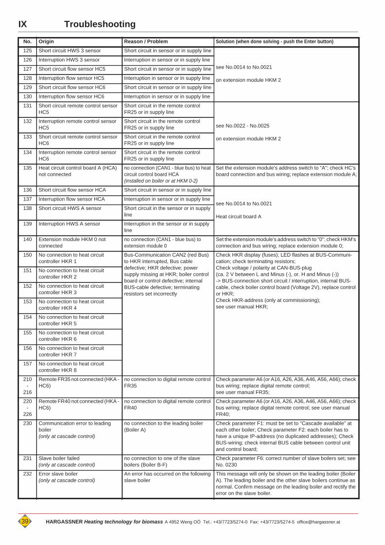
No. Origin Reason / Problem Solution (when done solving - push the Enter button)
125 Short circuit HWS 3 sensor Short circuit in sensor or in supply line
see No.0014 to No.0021
on extension module HKM 2
126 Interruption HWS 3 sensor Interruption in sensor or in supply line
127 Short circuit flow sensor HC5 Short circuit in sensor or in supply line
128 Interruption flow sensor HC5 Interruption in sensor or in supply line
129 Short circuit flow sensor HC6 Short circuit in sensor or in supply line
130 Interruption flow sensor HC6 Interruption in sensor or in supply line
131 Short circuit remote control sensor HC5
Short circuit in the remote control FR25 or in supply line
see No.0022 - No.0025
on extension module HKM 2
132 Interruption remote control sensor HC5
Short circuit in the remote control FR25 or in supply line
133 Short circuit remote control sensor HC6
Short circuit in the remote control FR25 or in supply line
134 Interruption remote control sensor HC6
Short circuit in the remote control FR25 or in supply line
135 Heat circuit control board A (HCA) not connected
no connection (CAN1 - blue bus) to heat circuit control board HCA(installed on boiler or at HKM 0-2)
Set the extension module's address switch to "A"; check HC's board connection and bus wiring; replace extension module A;
136 Short circuit flow sensor HCA Short circuit in sensor or in supply line
see No.0014 to No.0021
Heat circuit board A
137 Interruption flow sensor HCA Interruption in sensor or in supply line
138 Short circuit HWS A sensor Short circuit in the sensor or in supply line
139 Interruption HWS A sensor Interruption in the sensor or in supply line
140 Extension module HKM 0 not connected
no connection (CAN1 - blue bus) to extension module 0
Set the extension module's address switch to "0"; check HKM's connection and bus wiring; replace extension module 0;
150 No connection to heat circuit controller HKR 1
Bus-Communication CAN2 (red Bus) to HKR interrupted, Bus cable defective; HKR defective; power supply missing at HKR; boiler control board or control defective; internal BUS-cable defective; terminating resistors set incorrectly
Check HKR display (fuses); LED flashes at BUS-Communi-cation; check terminating resistors; Check voltage / polarity at CAN-BUS-plug(ca. 2 V between L and Minus (-), or. H and Minus (-)) -> BUS-connection short circuit / interruption, internal BUS-cable, check boiler control board (Voltage 2V), replace control or HKR;Check HKR-address (only at commissioning);see user manual HKR;
151 No connection to heat circuit controller HKR 2
152 No connection to heat circuit controller HKR 3
153 No connection to heat circuit controller HKR 4
154 No connection to heat circuit controller HKR 5
155 No connection to heat circuit controller HKR 6
156 No connection to heat circuit controller HKR 7
157 No connection to heat circuit controller HKR 8
210-
216
Remote FR35 not connected (HKA - HC6)
no connection to digital remote control FR35
Check parameter A6 (or A16, A26, A36, A46, A56, A66); check bus wiring; replace digital remote control;see user manual FR35;
220-
226
Remote FR40 not connected (HKA - HC6)
no connection to digital remote control FR40
Check parameter A6 (or A16, A26, A36, A46, A56, A66); check bus wiring; replace digital remote control; see user manual FR40;
230 Communication error to leading boiler (only at cascade control)
no connection to the leading boiler (Boiler A)
Check parameter F1: must be set to "Cascade available" at each other boiler; Check parameter F2: each boiler has to have a unique IP-address (no duplicated addresses); Check BUS-wiring; check internal BUS cable between control unit and control board;
231 Slave boiler failed(only at cascade control)
no connection to one of the slave boilers (Boiler B-F)
Check parameter F6: correct number of slave boilers set; see No. 0230
232 Error slave boiler(only at cascade control)
An error has occurred on the following slave boiler
This message will only be shown on the leading boiler (Boiler A). The leading boiler and the other slave boilers continue as normal. Confirm message on the leading boiler and rectify the error on the slave boiler.
39 HARGASSNER Heating technology for biomass A 4952 Weng OÖ Tel.: +43/7723/5274-0 Fax: +43/7723/5274-5 [email protected]
IXTroubleshooting
No. Origin Reason / Problem Solution (when done solving - push the Enter button)
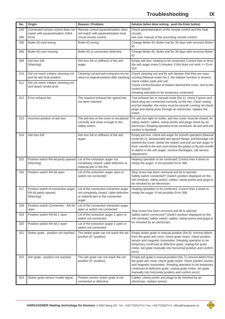
240-
246
Connected remote control does not match with parametrisation (HKA - HC6)
Remote control parametrisation does not match with parametrisation heat circuit remote control
Check parametrisation of the remote control and the heat circuits;see user manual of the according remote control;
305 Boiler-ID-card wrong Boiler-ID wrong Change Boiler-ID, Boiler trial for 30 days with incorrect Boiler-ID
306 Boiler-ID-card missing Boiler-ID or connection defective Change Boiler-ID, Boiler trial for 30 days with incorrect Boiler-ID
309 Ash box full!(Warning)
Ash box full or stiffness of the ash auger
Empty ash box; Heating to be continued; Control tries to drive the ash auger every 5 minutes; if this does not work => Error 314
310 Did not reach initiator cleaning rod and de-ash final position
Cleaning rod and ash extraction do not return to original position after cleaning
Check cleaning rod and fly ash damper that they are easy running (Manual mode No.2, the initiator function is shown), check rubber pads and rod;Check correct function of initiator (behind the cover, next to the control board); (Heating operation to be temporary continued)
311 Did not reach initiator cleaning rod and deash stroke level
312 Error exhaust fan The required exhaust fan speed has not been reached
Test exhaust fan in manual mode (No.1); check if green and black plug are connected correctly on the fan; Clean casing and fan impeller, the motor must be smooth running; let check plugs and clamp ports through an electrician; replace the motor;
313 Incorrect position of ash box The ash box or the cover is not placed correctly and close enough to the safety switch.
Fix ash box tight on boiler; ash box cover must be closed; let safety switch, cables, clamp points and plugs check by an electrician; (heating operation to be continued, de-ash and ash suction is blocked)
314 Ash box full! Ash box full or stiffness of the ash auger
Empty ash box, check ash auger for smooth operation (Manual mode No.2); disassemble ash ejector flange, pull blockage rod (behind the cover, below the stoker) and pull out ash auger in front; overfill in the ash room below the grates or fly ash overfill or debris in the ash auger; remove blockages; call service department:
315 Position switch RA-lid partly opened(Warning)
Lid of the extraction auger not completely closed, cable defective or material jam in the RA
Heating operation to be continued; Control tries 4 times to empty the auger; if not possible Error 366
316 Position switch RA-lid open Lid of the extraction auger open or switch not connected
Stop screw has been removed and lid is opened; Safety switch connected? (Switch position displayed on the Info window); safety switch, cables, clamp points and plugs to be checked by an electrician;
317 Position switch of connection auger RA-lid partly opened(Warning)
Lid of the connection extraction auger not completely closed, cable defective or material jam in the connection auger
Heating operation to be continued; Control tries 4 times to empty the auger; if not possible Error 368
318 Position switch Connection - RA-lid open
Lid of the connection extraction auger open or switch not connected Stop screw has been removed and lid is opened;
Safety switch connected? (Switch position displayed on the Info window); safety switch, cables, clamp points and plugs to be checked by an electrician;
319 Position switch RA-lid 1 open Lid of the extraction auger 1 open or switch not connected
320 Position switch RA-lid 2 open Lid of the extraction auger 2 open or switch not connected
321 Stoker grate - position not reached The stoker grate can not reach the set position (0° position)
Empty stoker grate in manual position (No.6); remove debris from the grate ash room; check grate motor; check position sensor and magnetic transmitter; (Heating operation to be temporary continued at defective grate, unplug the grate motor, set grate manually into horizontal position and confirm error)
322 Ash grate - position not reached The ash grate can not reach the set position (0° position)
Empty ash grate in manual position (No.7); remove debris from the grate ash room; check grate motor; check position sensor and magnetic transmitter; (Heating operation to be temporary continued at defective grate, unplug grate motor, set grate manually into horizontal position and confirm error)
323 Stoker-grate sensor invalid signal Position sensor stoker grate is not connected or defective
Cables, clamp points and plugs to be checked by an electrician, replace sensor;
HARGASSNER Heating technology for biomass A 4952 Weng OÖ Tel.: +43/7723/5274-0 Fax: +43/7723/5274-5 [email protected] 40

IX Troubleshooting
No. Origin Reason / Problem Solution (when done solving - push the Enter button)
324 Ash-grate sensor invalid signal Position sensor ash grate is not connected or defective
Cables, clamp points and plugs to be checked by an electrician, replace sensor;
325 Primary air flap defective The primary air flap can not reach the set position or does not move
Test primary air flap in manual mode (No.12); Through pressing the release, the primary air flap can be moved manually and may be checked to smooth operation. (behind the covers, below the stoker); (Heating operation may be temporary continued at defective primary flap, therefore set manually to 30%); cables, clamp points and plugs to be checked by an electrician; replace flap motor
326 Primary air flap not connected Primary air flap is not connected or defective
(Heating operation may be temporary continued at defective primary flap, therefore set manually to 30%); cables, clamp points and plugs to be checked by an electrician; replace flap motor
327 Fuel level sensor invalid signal Position sensor ash grate is not connected or defective
(Heating operation may be temporary continued at defective sensor, therefore disconnect sensor and enter); cables, clamp points and plugs to be checked by an electrician; replace sensor;
328 Emergency stop has been operated
Emergency stop operated or plug with bridge removed
Unlock emergency stop or re-insert plug with bridgeClamp (64 / 65)
329 Negative pressure sensor defective Negative pressure box is not connected or defective
(Heating operation may be temporary continued at defective sensor (with reduced heating output), therefore disconnect sensor and enter); cables, clamp points and plugs to be checked by an electrician; replace sensor;
330 Safety bridge relays defective Board defective Replace board and call service department.
331 Safety switch storage room open Emergency stop operated or plug with bridge removed
Unlock emergency stop or re-insert plug with bridge
335 Temperature in fuel storage room 2 exceeded
Temperature in fuel storage room 2 exceeded
If the warning device in the fuel storage room (TÜB) triggers, immediately initiate further measures (call fire department); if the error is due to a defective control board, the heating operation may be temporary continued with without the TÜB sensor;(Set parameter D21 to "not available" => DANGER: no warning at exceeded fuel storage room temperature!)
336 Temperature in fuel storage room exceeded
Temperature in fuel storage room exceeded
337 Temperature in the stoker auger exceeded
The temperature on the stoker auger is high, because the flue connection is minimised or a burn back occured
Check boiler, flue pipe and exhaust fan for dust or ash and clean; if burn back, check the tightness of the rotary valve; remove the tube from the negative pressure box and blow in direction of the boiler.
338 Interruption TÜB 2 sensor
Interruption or short circuit in the sensor or in supply line
see No.0014 to No.0021
the heating operation may be temporary continued without TÜB;(Set parameter D21 to "not available" => DANGER: no warning at exceeded fuel storage room temperature!)
339 Short circuit TÜB 2 sensor
340 Interruption TÜB sensor
341 Short circuit TÜB sensor
342 Interruption ETÜ sensor
343 Short circuit ETÜ sensor
344 Negative pressure too low The speed-controlled exhaust fan does not reach the desired negative pressure in the boiler
all boiler openings must be closed (Maintenance openings, combustion door); check neg. pressure box, exhaust fan and flue pipe; blow through neg. pressure tube in direction of the boiler; Check clamp points, cables and plugs;
349 Lambda sensor not connected or defective
Contact error of the lambda sensor or lambda sensor defective
Lambda sensor very intensely dirtied (clean), then perform a function check in manual mode No. 13; let check terminal points and plugs by an electrician; replace the lambda sensor; the boiler system can run without lambda sensor with reduced heating output until replacement; disconnect lambda sensor and confirm;
41 HARGASSNER Heating technology for biomass A 4952 Weng OÖ Tel.: +43/7723/5274-0 Fax: +43/7723/5274-5 [email protected]
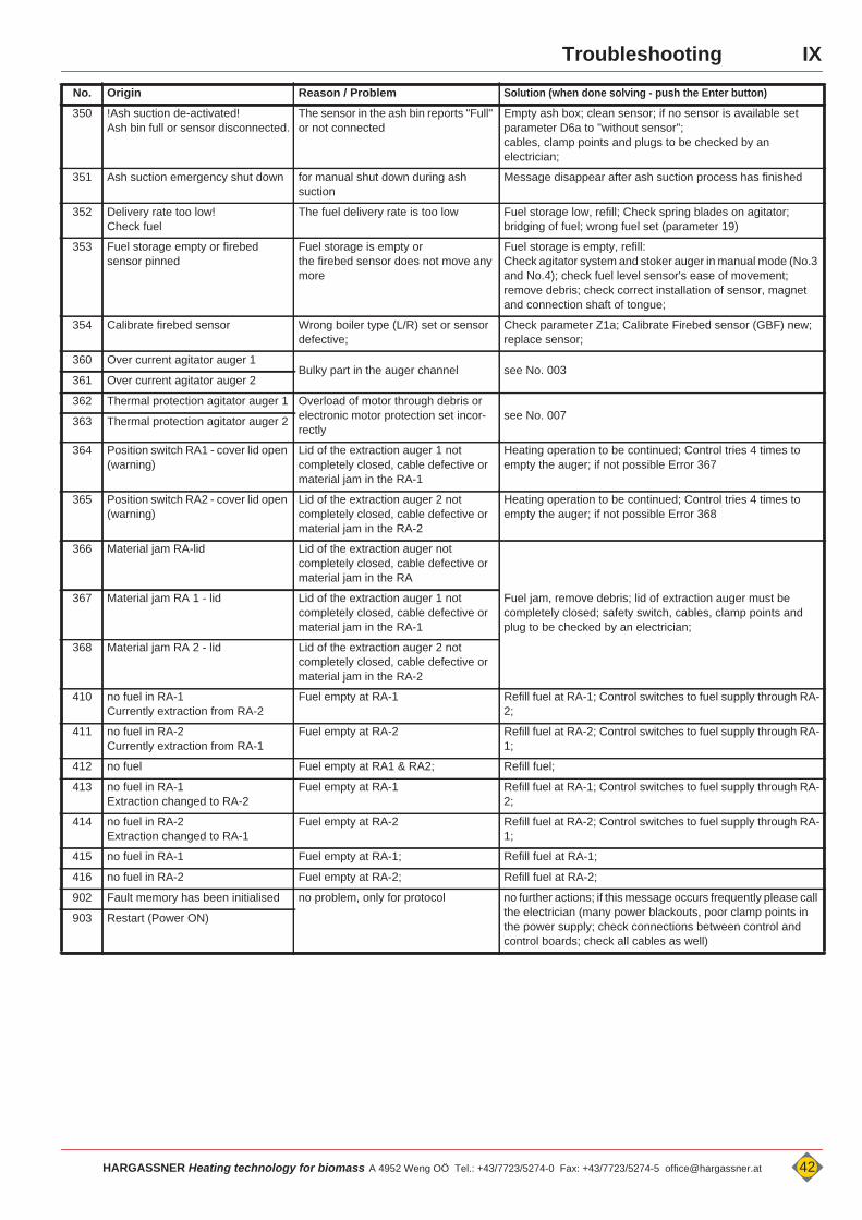
IXTroubleshooting
No. Origin Reason / Problem Solution (when done solving - push the Enter button)
350 !Ash suction de-activated!Ash bin full or sensor disconnected.
The sensor in the ash bin reports "Full" or not connected
Empty ash box; clean sensor; if no sensor is available set parameter D6a to "without sensor";cables, clamp points and plugs to be checked by an electrician;
351 Ash suction emergency shut down for manual shut down during ash suction
Message disappear after ash suction process has finished
352 Delivery rate too low!Check fuel
The fuel delivery rate is too low Fuel storage low, refill; Check spring blades on agitator; bridging of fuel; wrong fuel set (parameter 19)
353 Fuel storage empty or firebed sensor pinned
Fuel storage is empty or the firebed sensor does not move any more
Fuel storage is empty, refill:Check agitator system and stoker auger in manual mode (No.3 and No.4); check fuel level sensor's ease of movement; remove debris; check correct installation of sensor, magnet and connection shaft of tongue;
354 Calibrate firebed sensor Wrong boiler type (L/R) set or sensor defective;
Check parameter Z1a; Calibrate Firebed sensor (GBF) new; replace sensor;
360 Over current agitator auger 1Bulky part in the auger channel see No. 003
361 Over current agitator auger 2
362 Thermal protection agitator auger 1 Overload of motor through debris or electronic motor protection set incor-rectly
see No. 007363 Thermal protection agitator auger 2
364 Position switch RA1 - cover lid open (warning)
Lid of the extraction auger 1 not completely closed, cable defective or material jam in the RA-1
Heating operation to be continued; Control tries 4 times to empty the auger; if not possible Error 367
365 Position switch RA2 - cover lid open (warning)
Lid of the extraction auger 2 not completely closed, cable defective or material jam in the RA-2
Heating operation to be continued; Control tries 4 times to empty the auger; if not possible Error 368
366 Material jam RA-lid Lid of the extraction auger not completely closed, cable defective or material jam in the RA
Fuel jam, remove debris; lid of extraction auger must be completely closed; safety switch, cables, clamp points and plug to be checked by an electrician;
367 Material jam RA 1 - lid Lid of the extraction auger 1 not completely closed, cable defective or material jam in the RA-1
368 Material jam RA 2 - lid Lid of the extraction auger 2 not completely closed, cable defective or material jam in the RA-2
410 no fuel in RA-1Currently extraction from RA-2
Fuel empty at RA-1 Refill fuel at RA-1; Control switches to fuel supply through RA-2;
411 no fuel in RA-2Currently extraction from RA-1
Fuel empty at RA-2 Refill fuel at RA-2; Control switches to fuel supply through RA-1;
412 no fuel Fuel empty at RA1 & RA2; Refill fuel;
413 no fuel in RA-1Extraction changed to RA-2
Fuel empty at RA-1 Refill fuel at RA-1; Control switches to fuel supply through RA-2;
414 no fuel in RA-2Extraction changed to RA-1
Fuel empty at RA-2 Refill fuel at RA-2; Control switches to fuel supply through RA-1;
415 no fuel in RA-1 Fuel empty at RA-1; Refill fuel at RA-1;
416 no fuel in RA-2 Fuel empty at RA-2; Refill fuel at RA-2;
902 Fault memory has been initialised no problem, only for protocol no further actions; if this message occurs frequently please call the electrician (many power blackouts, poor clamp points in the power supply; check connections between control and control boards; check all cables as well)
903 Restart (Power ON)
HARGASSNER Heating technology for biomass A 4952 Weng OÖ Tel.: +43/7723/5274-0 Fax: +43/7723/5274-5 [email protected] 42
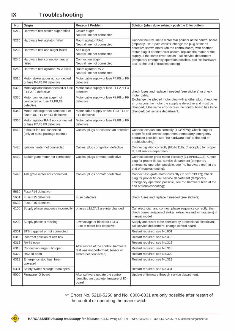
IX Troubleshooting
Errors No. 5210-5250 and No. 6300-6331 are only possible after restart of the control or operating the main switch
No. Origin Reason / Problem Solution (when done solving - push the Enter button)
5210 Hardware test stoker auger failed Stoker augerNeutral line not connected
Connect neutral line to motor star point or at the control board (implicitly use 5-pole cable!); change the plug of the as defective shown motor (on the control board) with another motor plug, if another error occurs, replace the motor or the supply, if the same error occurs - call service department (temporary emergency operation possible, see "no hardware test" at the end of troubleshooting)
5220 Hardware test agitator failed Room agitator RA-1Neutral line not connected
5230 Hardware test ash auger failed Ash augerNeutral line not connected
5240 Hardware test connection auger failed
Connection augerNeutral line not connected
5250 Hardware test agitator RA-2 failed Room agitator RA-2Neutral line not connected
5310 Motor stoker auger not connected or fuse F4,F5,F6 defective
Motor cable supply or fuse F4,F5 or F6 defective
check fuses and replace if needed (see stickers) or check motor cable;Exchange the alleged motor plug with another plug, if another error occurs the motor the supply is defective and must be changed; if the same error occurs the control board has to be changed; call service department;
5320 Motor agitator not connected or fuse F1,F2,F3 defective
Motor cable supply or fuse F1,F2 or F3 defective
5330 Motor connection auger not connected or fuse F7,F8,F9 defective
Motor cable supply or fuse F7,F8 or F9 defective
5340 Motor ash auger not connected or fuse F10, F11 or F12 defective.
Motor cable supply or fuse F10,F11 or F12 defective
5350 Motor agitator RA-2 not connected or fuse F7,F8,F9 defective
Motor cable supply or fuse F7,F8 or F9 defective
5410 Exhaust fan not connected(only at pulse package control)
Cables, plugs or exhaust fan defective Connect exhaust fan correctly (113/PE/N); Check plug for proper fit; call service department (temporary emergency operation possible, see "no hardware test" at the end of troubleshooting);
5420 Ignition heater not connected Cables, plugs or ignition defective Connect ignition correctly (PE/N/118); Check plug for proper fit; call service department;
5430 Stoker grate motor not connected Cables, plugs or motor defective Connect stoker grate motor correctly (114/PE/N/115); Check plug for proper fit; call service department (temporary emergency operation possible, see "no hardware test" at the end of troubleshooting);
5440 Ash grate motor not connected Cables, plugs or motor defective Connect ash grate motor correctly (116/PE/N/117); Check plug for proper fit; call service department (temporary emergency operation possible, see "no hardware test" at the end of troubleshooting);
5630 Fuse F14 defective
Fuse defective check fuses and replace if needed (see stickers) 5631 Fuse F15 defective
5632 Fuse F16 defective
6100 Supply phase sequence incorrectly phases L1/L2/L3 are interchanged Call electrician and connect phase sequence correctly; then check correct rotation of stoker, extraction and ash auger(s) in manual mode!
6200 Supply phase is missing Low voltage or blackout L2/L3Fuse in meter box defective.
Supply and fuses to be checked by professional electrician; call service department, change control board.
6301 STB triggered or not connected
After restart of the control, hardware test was not performed; sensor or switch not connected;
Restart required; see No.001
6313 Incorrect position of ash box Restart required; see No.313
6316 RA-lid open Restart required; see No.316
6318 Connection auger - lid open Restart required; see No.318
6320 RA2-lid open Restart required; see No.320
6328 Emergency stop has been operated
Restart required; see No.328
6331 Safety switch storage room open Restart required; see No.331
9000 Firmware IO-board After software update the control identified an obsolete firmware of IO-board
Update of firmware through service department;
43 HARGASSNER Heating technology for biomass A 4952 Weng OÖ Tel.: +43/7723/5274-0 Fax: +43/7723/5274-5 [email protected]
IXTroubleshooting
2.1 Temporary emergency operation (Restart without HW-test)
If the error is clearly a result of a defective control board, and the connected component works correctly; the control may be run in temporary emergency operation (until the service department arrives) without Hardware-Test.
switch to operation mode „MANUAL“ on the display navigate to the according manual parameter confirm <without HW-test>
Boiler operates with max. 60% heating output
HARGASSNER Heating technology for biomass A 4952 Weng OÖ Tel.: +43/7723/5274-0 Fax: +43/7723/5274-5 [email protected] 44
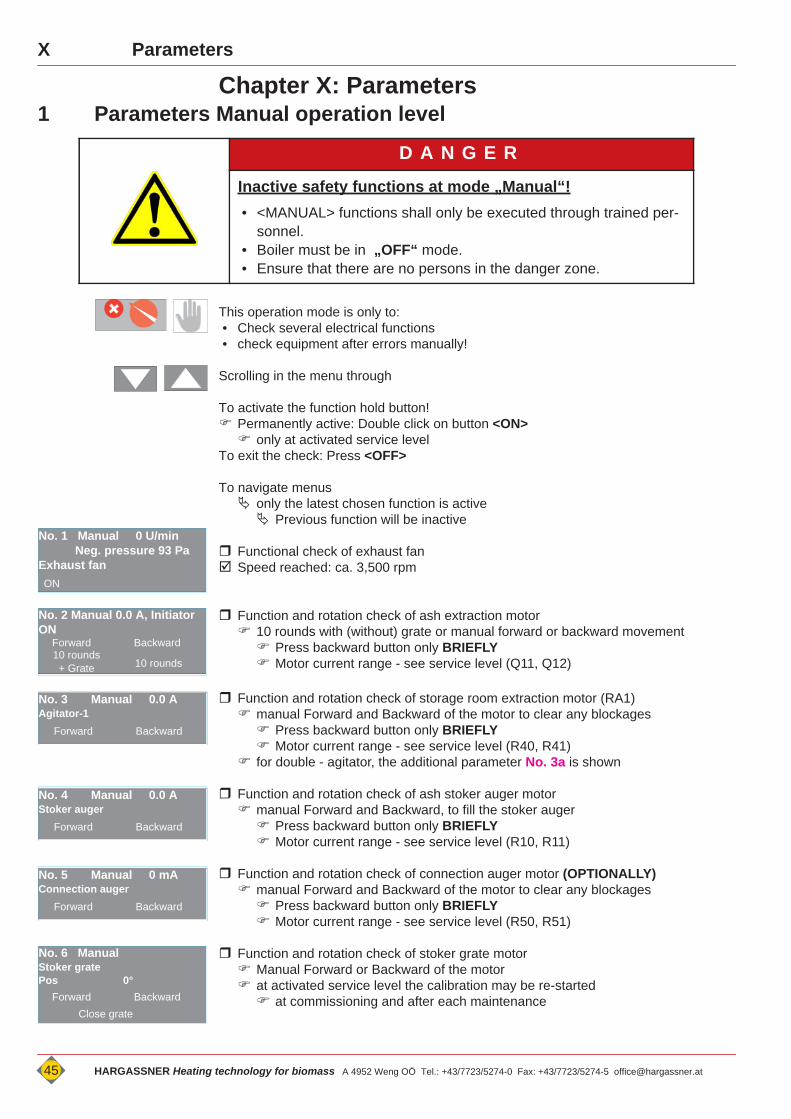
X Parameters
X
Chapter X: Parameters1 Parameters Manual operation level
This operation mode is only to:• Check several electrical functions• check equipment after errors manually!
Scrolling in the menu through
To activate the function hold button! Permanently active: Double click on button <ON> only at activated service level
To exit the check: Press <OFF>
To navigate menus only the latest chosen function is active Previous function will be inactive
Functional check of exhaust fan Speed reached: ca. 3,500 rpm
Function and rotation check of ash extraction motor 10 rounds with (without) grate or manual forward or backward movement Press backward button only BRIEFLY Motor current range - see service level (Q11, Q12)
Function and rotation check of storage room extraction motor (RA1) manual Forward and Backward of the motor to clear any blockages Press backward button only BRIEFLY Motor current range - see service level (R40, R41)
for double - agitator, the additional parameter No. 3a is shown
Function and rotation check of ash stoker auger motor manual Forward and Backward, to fill the stoker auger Press backward button only BRIEFLY Motor current range - see service level (R10, R11)
Function and rotation check of connection auger motor (OPTIONALLY) manual Forward and Backward of the motor to clear any blockages Press backward button only BRIEFLY Motor current range - see service level (R50, R51)
Function and rotation check of stoker grate motor Manual Forward or Backward of the motor at activated service level the calibration may be re-started at commissioning and after each maintenance
D A N G E R
Inactive safety functions at mode „Manual“!• <MANUAL> functions shall only be executed through trained per-
sonnel.• Boiler must be in „OFF“ mode.• Ensure that there are no persons in the danger zone.
No. 1 Manual 0 U/min Neg. pressure 93 Pa Exhaust fanON
No. 2 Manual 0.0 A, Initiator ON
Forward Backward10 rounds+ Grate 10 rounds
No. 3 Manual 0.0 AAgitator-1
Forward Backward
No. 4 Manual 0.0 AStoker auger
Forward Backward
No. 5 Manual 0 mAConnection auger
Forward Backward
No. 6 ManualStoker gratePos 0°
Forward BackwardClose grate
45 HARGASSNER Heating technology for biomass A 4952 Weng OÖ Tel.: +43/7723/5274-0 Fax: +43/7723/5274-5 [email protected]
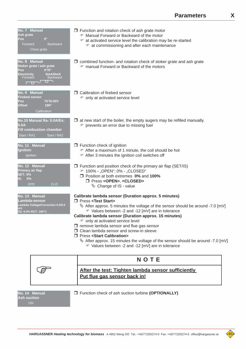
XParameters
Function and rotation check of ash grate motor Manual Forward or Backward of the motor at activated service level the calibration may be re-started at commissioning and after each maintenance
combined function- and rotation check of stoker grate and ash grate manual Forward or Backward of the motors
Calibration of firebed sensor only at activated service level
at new start of the boiler, the empty augers may be refilled manually. prevents an error due to missing fuel
Function check of ignition After a maximum of 1 minute, the coil should be hot After 3 minutes the ignition coil switches off
Function and position check of the primary air flap (SET/IS) 100% - „OPEN“; 0% - „CLOSED“ Position at both extremes 0% and 100% Press <OPEN>, <CLOSED> Change of IS - value
Calibrate lambda sensor (Duration approx. 5 minutes) Press <Test Start> After approx. 5 minutes the voltage of the sensor should be around -7.0 [mV] Values between -2 and -12 [mV] are in tolerance
Calibrate lambda sensor (Duration approx. 15 minutes) only at activated service level
remove lambda sensor and flue gas sensor Clean lambda sensor and screw-in sleeve Press <Start Calibration> After approx. 15 minutes the voltage of the sensor should be around -7.0 [mV] Values between -2 and -12 [mV] are in tolerance
Function check of ash suction turbine (OPTIONALLY)
No. 7 ManualAsh gratePos 0°
Forward BackwardClose grate
No. 8 ManualStoker grate / ash gratePos 0°/0°Electricity 0mA/0mA
Forward Backward
No. 9 ManualFirebed sensorPos 75°/0.00VOffset 190°
Calibration
No.10 Manual Ra: 0.0A/Es: 0.0AFill combustion chamberStart / RA1 Start / RA2
No. 11 ManualIgnition
Ignition
No. 12 ManualPrimary air flapSET: 0%IS: 0%
OPE CLO
No. 13 ManualLambda-sensor Lambda Voltage/Correction 0.0/0.0 mVO2: 6.0% RGT: 160°CL t b il l d til fl t i
N O T E
After the test: Tighten lambda sensor sufficiently Put flue gas sensor back in!
No. 14 ManualAsh suction
ON
HARGASSNER Heating technology for biomass A 4952 Weng OÖ Tel.: +43/7723/5274-0 Fax: +43/7723/5274-5 [email protected] 46
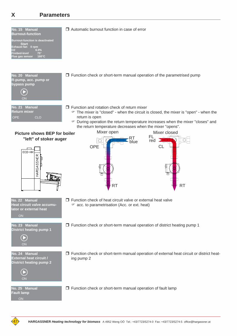
X Parameters
Automatic burnout function in case of error
Function check or short-term manual operation of the parametrised pump
Function and rotation check of return mixer The mixer is "closed" - when the circuit is closed, the mixer is "open" - when the
return is open During operation the return temperature increases when the mixer "closes" and
the return temperature decreases when the mixer "opens".
Function check of heat circuit valve or external heat valve acc. to parametrisation (Acc. or ext. heat)
Function check or short-term manual operation of district heating pump 1
Function check or short-term manual operation of external heat circuit or district heat-ing pump 2
Function check or short-term manual operation of fault lamp
No. 15 ManualBurnout-functionBurnout-function is deactivated
Exhaust fan 0 rpmO2 6.0%Firebed-level 75°Flue gas sensor 160°C
Start
No. 20 ManualR-pump, acc. pump or bypass pump
ON
No. 21 ManualReturn mixerOPE CLO
Mixer closedMixer open
CLOPE
FLRT
RTRT
blue redPicture shows BEP for boiler
"left" of stoker auger
No. 22 ManualHeat circuit valve accumu-lator or external heat
ON
No. 23 ManualDistrict heating pump 1
ON
No. 24 ManualExternal heat circuit / District heating pump 2
ON
No. 25 ManualFault lamp
ON
47 HARGASSNER Heating technology for biomass A 4952 Weng OÖ Tel.: +43/7723/5274-0 Fax: +43/7723/5274-5 [email protected]
XParameters
Function check or short-term manual operation of the horn - TÜB
Function check or short-term manual operation of HWS loading pump 1 only at connected HKM 0 No. 40, 50 and 60 for HWS pump A, 2 and 3 HWS pump A, 2 and 3 only at connected HKM A, HKM 1 and HKM 2
Function check or short-term manual operation of HWS circulation pump 1 only at connected HKM 0 No. 41, 51 and 61 for HWS circulation pump A, 2 and 3 HWS circulation pump A, 2 and 3 only at connected HKM A, HKM 1 and HKM 2
Function check or short-term manual operation of heat circuit pump 1 only at connected HKM 0 No. 42, 52 and 62 for Heat circuit pump A, 3 and 5 HWS pump A, 3 and 5 only at connected HKM A, HKM 1 and HKM 2
Function and rotation check of mixer - heat circuit 1 only at connected HKM 0 No. 43, 53 and 63 for heat circuit mixer A, 3 and 5 Heat circuit mixer A, 3 and 5 only at connected HKM A, HKM 1 and HKM 2
Function check or short-term manual operation of heat circuit pump 2 only at connected HKM 0 No. 44, 54 and 64 for Heat circuit pump A, 4 and 6 HWS pump A, 4 and 6 only at connected HKM A, HKM 1 and HKM 2
Function and rotation check of mixer - heat circuit 2 only at connected HKM 0 No. 45, 55 and 65 for heat circuit mixer A, 4 and 6 Heat circuit mixer A, 4 and 6 only at connected HKM A, HKM 1 and HKM 2
Function check or short-term manual operation of external heat circuit pump 1 only at connected HKM 0 No. 56 and 66 for external heat circuit pump 2 and 3 external heat circuit pump 2 and 3 only at connected HKM 1 and HKM 2
Display of the current sensor values acc. to parametrised heating system
No. 26 ManualHorn TÜB (Temperature
ON
No. 30 ManualHWS pump 1
ON
No. 31 ManualCirculation pump HWS 1
ON
No. 32 ManualHeat circuit pump 1
ON
No. 33 ManualMixer heat circuit 1OPE CLO
No. 34 ManualHeat circuit pump 2
ON
No. 35 ManualMixer heat circuit 2OPE CLO
No. 36 ManualExternal heat circuit pump 1
ON
No. 70 - No. 74 Manual
Boiler sensor 72°CFlue gas sensor 160°CReturn sensor 61°CAcc. temp. top 72°CAcc. temp. mid 56°CAcc. temp. bottom 30°C
HARGASSNER Heating technology for biomass A 4952 Weng OÖ Tel.: +43/7723/5274-0 Fax: +43/7723/5274-5 [email protected] 48
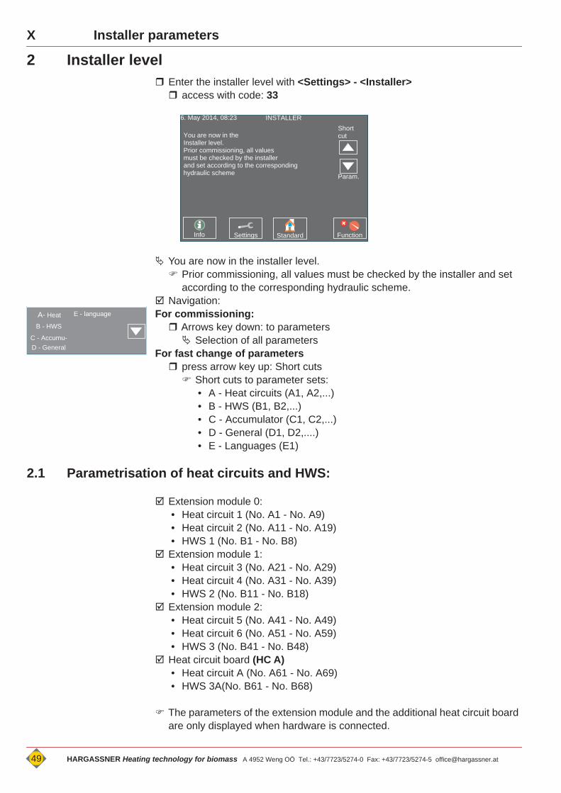
X Installer parameters Installer parameters X
2 Installer level Enter the installer level with <Settings> - <Installer> access with code: 33
You are now in the installer level. Prior commissioning, all values must be checked by the installer and set
according to the corresponding hydraulic scheme. Navigation:For commissioning: Arrows key down: to parameters Selection of all parameters
For fast change of parameters press arrow key up: Short cuts Short cuts to parameter sets:
• A - Heat circuits (A1, A2,...)• B - HWS (B1, B2,...)• C - Accumulator (C1, C2,...)• D - General (D1, D2,....)• E - Languages (E1)
2.1 Parametrisation of heat circuits and HWS:
Extension module 0:• Heat circuit 1 (No. A1 - No. A9)• Heat circuit 2 (No. A11 - No. A19)• HWS 1 (No. B1 - No. B8)
Extension module 1:• Heat circuit 3 (No. A21 - No. A29)• Heat circuit 4 (No. A31 - No. A39)• HWS 2 (No. B11 - No. B18)
Extension module 2:• Heat circuit 5 (No. A41 - No. A49)• Heat circuit 6 (No. A51 - No. A59)• HWS 3 (No. B41 - No. B48)
Heat circuit board (HC A)• Heat circuit A (No. A61 - No. A69)• HWS 3A(No. B61 - No. B68)
The parameters of the extension module and the additional heat circuit board are only displayed when hardware is connected.
6. May 2014, 08:23 INSTALLER
You are now in the Installer level.Prior commissioning, all valuesmust be checked by the installerand set according to the corresponding hydraulic scheme
Info
Short cut
Settings Standard Function
Param.
A- Heat
B - HWS
C - Accumu-D - General
E - language
49 HARGASSNER Heating technology for biomass A 4952 Weng OÖ Tel.: +43/7723/5274-0 Fax: +43/7723/5274-5 [email protected]
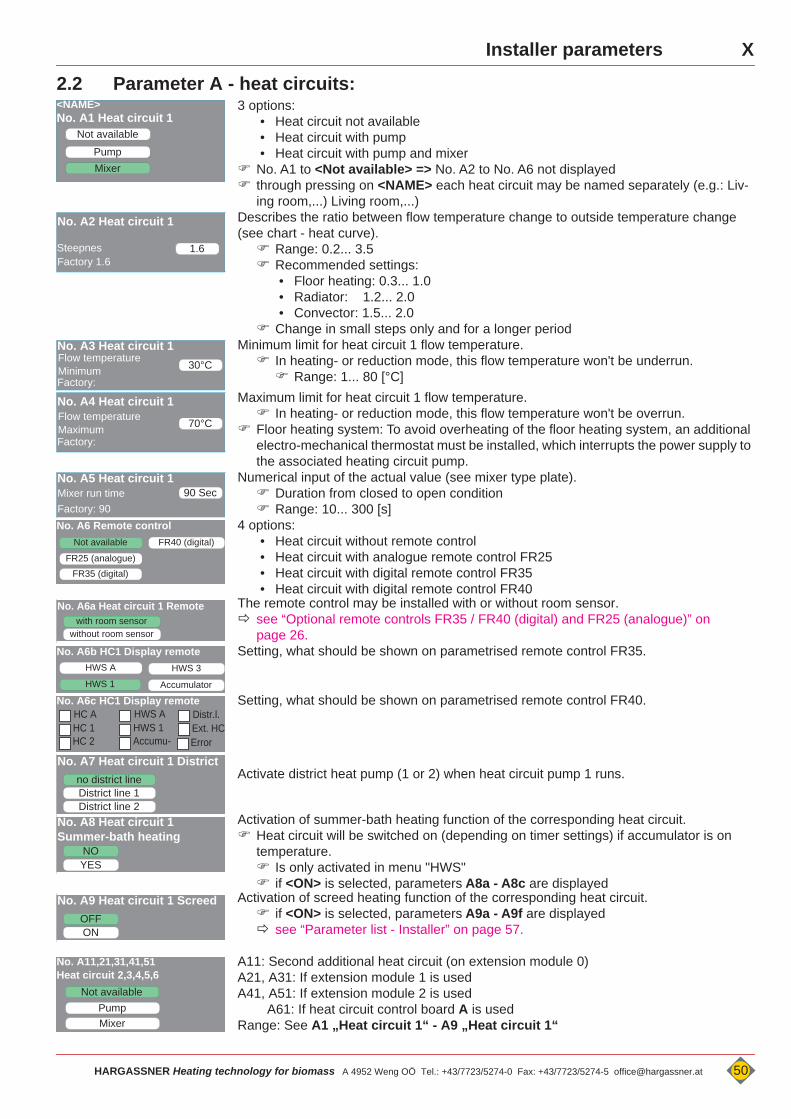
XInstaller parameters
2.2 Parameter A - heat circuits: 3 options:
• Heat circuit not available• Heat circuit with pump• Heat circuit with pump and mixer
No. A1 to <Not available> => No. A2 to No. A6 not displayed through pressing on <NAME> each heat circuit may be named separately (e.g.: Liv-
ing room,...) Living room,...) Describes the ratio between flow temperature change to outside temperature change
(see chart - heat curve). Range: 0.2... 3.5 Recommended settings:
• Floor heating: 0.3... 1.0• Radiator: 1.2... 2.0• Convector: 1.5... 2.0
Change in small steps only and for a longer period Minimum limit for heat circuit 1 flow temperature.
In heating- or reduction mode, this flow temperature won't be underrun. Range: 1... 80 [°C]
Maximum limit for heat circuit 1 flow temperature. In heating- or reduction mode, this flow temperature won't be overrun.
Floor heating system: To avoid overheating of the floor heating system, an additional electro-mechanical thermostat must be installed, which interrupts the power supply to the associated heating circuit pump.
Numerical input of the actual value (see mixer type plate). Duration from closed to open condition Range: 10... 300 [s]
4 options:• Heat circuit without remote control• Heat circuit with analogue remote control FR25• Heat circuit with digital remote control FR35• Heat circuit with digital remote control FR40
The remote control may be installed with or without room sensor. see “Optional remote controls FR35 / FR40 (digital) and FR25 (analogue)” on
page 26.Setting, what should be shown on parametrised remote control FR35.
Setting, what should be shown on parametrised remote control FR40.
Activate district heat pump (1 or 2) when heat circuit pump 1 runs.
Activation of summer-bath heating function of the corresponding heat circuit. Heat circuit will be switched on (depending on timer settings) if accumulator is on
temperature. Is only activated in menu "HWS" if <ON> is selected, parameters A8a - A8c are displayed
Activation of screed heating function of the corresponding heat circuit. if <ON> is selected, parameters A9a - A9f are displayed see “Parameter list - Installer” on page 57.
A11: Second additional heat circuit (on extension module 0)A21, A31: If extension module 1 is usedA41, A51: If extension module 2 is used A61: If heat circuit control board A is usedRange: See A1 „Heat circuit 1“ - A9 „Heat circuit 1“
MixerPump
No. A1 Heat circuit 1Not available
<NAME>
1.6
No. A2 Heat circuit 1
SteepnesFactory 1.6
30°C
No. A3 Heat circuit 1Flow temperature MinimumFactory:
70°C
No. A4 Heat circuit 1Flow temperature MaximumFactory:
90 SecNo. A5 Heat circuit 1Mixer run timeFactory: 90
Not available
FR25 (analogue)
No. A6 Remote control
FR35 (digital)
FR40 (digital)
with room sensorNo. A6a Heat circuit 1 Remote
without room sensor
HWS ANo. A6b HC1 Display remote
HWS 3
AccumulatorHWS 1
No. A6c HC1 Display remote HC AHC 1HC 2
HWS AHWS 1Accumu- Error
Distr.l.Ext. HC
no district line
No. A7 Heat circuit 1 District
District line 1District line 2
NO
No. A8 Heat circuit 1Summer-bath heating
YES
OFF
No. A9 Heat circuit 1 Screed
ON
Not availablePump
No. A11,21,31,41,51 Heat circuit 2,3,4,5,6
Mixer
HARGASSNER Heating technology for biomass A 4952 Weng OÖ Tel.: +43/7723/5274-0 Fax: +43/7723/5274-5 [email protected] 50
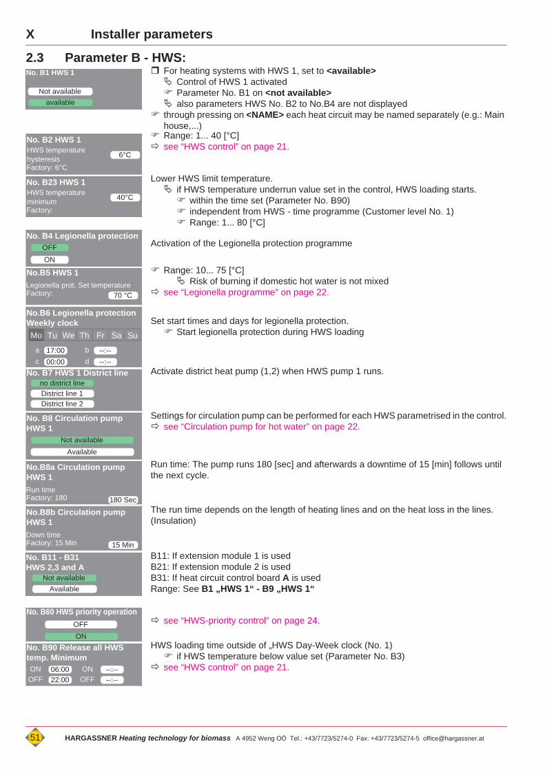
X Installer parameters
2.3 Parameter B - HWS: For heating systems with HWS 1, set to <available> Control of HWS 1 activated Parameter No. B1 on <not available> also parameters HWS No. B2 to No.B4 are not displayed
through pressing on <NAME> each heat circuit may be named separately (e.g.: Main house,...)
Range: 1... 40 [°C] see “HWS control” on page 21.
Lower HWS limit temperature. if HWS temperature underrun value set in the control, HWS loading starts. within the time set (Parameter No. B90) independent from HWS - time programme (Customer level No. 1) Range: 1... 80 [°C]
Activation of the Legionella protection programme
Range: 10... 75 [°C] Risk of burning if domestic hot water is not mixed
see “Legionella programme” on page 22.
Set start times and days for legionella protection. Start legionella protection during HWS loading
Activate district heat pump (1,2) when HWS pump 1 runs.
Settings for circulation pump can be performed for each HWS parametrised in the control. see “Circulation pump for hot water” on page 22.
Run time: The pump runs 180 [sec] and afterwards a downtime of 15 [min] follows until the next cycle.
The run time depends on the length of heating lines and on the heat loss in the lines. (Insulation)
B11: If extension module 1 is usedB21: If extension module 2 is usedB31: If heat circuit control board A is usedRange: See B1 „HWS 1“ - B9 „HWS 1“
see “HWS-priority control” on page 24.
HWS loading time outside of „HWS Day-Week clock (No. 1) if HWS temperature below value set (Parameter No. B3)
see “HWS control” on page 21.
Not availableavailable
No. B1 HWS 1
6°C
No. B2 HWS 1HWS temperature hysteresisFactory: 6°C
40°C
No. B23 HWS 1HWS temperature minimumFactory:
OFFNo. B4 Legionella protection
ON
70 °C
No.B5 HWS 1Legionella prot. Set temperatureFactory:
No.B6 Legionella protectionWeekly clock Mo Tu We Th Fr Sa Su
17:00a --:--b00:00c --:--d
no district lineNo. B7 HWS 1 District line
District line 1District line 2
Available
No. B8 Circulation pump HWS 1
Not available
180 Sec
No.B8a Circulation pump HWS 1 Run timeFactory: 180
15 Min
No.B8b Circulation pump HWS 1 Down timeFactory: 15 Min
Not availableAvailable
No. B11 - B31 HWS 2,3 and A
No. B60 HWS priority operation
ONOFF
06:00
No. B90 Release all HWS temp. MinimumONOFF 22:00
--:--ONOFF --:--
51 HARGASSNER Heating technology for biomass A 4952 Weng OÖ Tel.: +43/7723/5274-0 Fax: +43/7723/5274-5 [email protected]
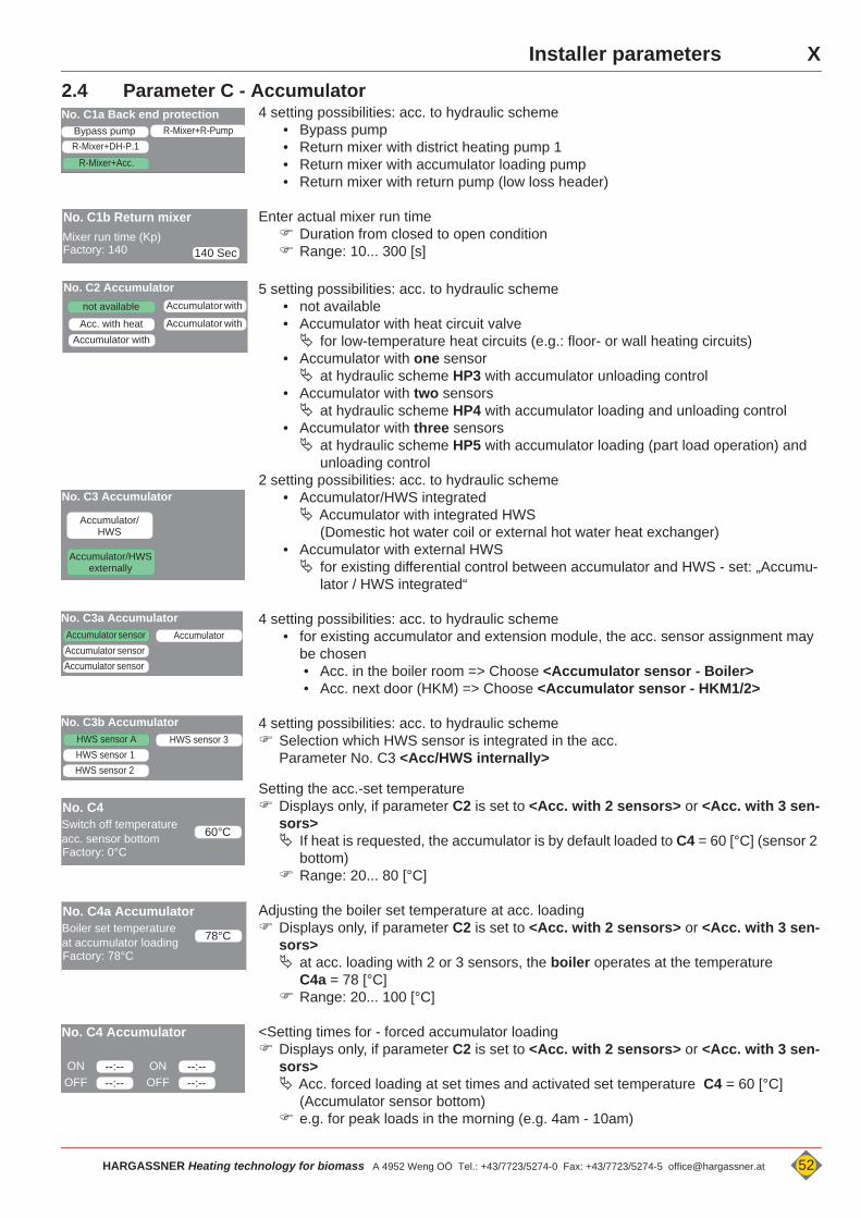
XInstaller parameters
2.4 Parameter C - Accumulator4 setting possibilities: acc. to hydraulic scheme
• Bypass pump• Return mixer with district heating pump 1• Return mixer with accumulator loading pump• Return mixer with return pump (low loss header)
Enter actual mixer run time Duration from closed to open condition Range: 10... 300 [s]
5 setting possibilities: acc. to hydraulic scheme• not available• Accumulator with heat circuit valve for low-temperature heat circuits (e.g.: floor- or wall heating circuits)
• Accumulator with one sensor at hydraulic scheme HP3 with accumulator unloading control
• Accumulator with two sensors at hydraulic scheme HP4 with accumulator loading and unloading control
• Accumulator with three sensors at hydraulic scheme HP5 with accumulator loading (part load operation) and
unloading control2 setting possibilities: acc. to hydraulic scheme
• Accumulator/HWS integrated Accumulator with integrated HWS
(Domestic hot water coil or external hot water heat exchanger)• Accumulator with external HWS for existing differential control between accumulator and HWS - set: „Accumu-
lator / HWS integrated“
4 setting possibilities: acc. to hydraulic scheme• for existing accumulator and extension module, the acc. sensor assignment may
be chosen• Acc. in the boiler room => Choose <Accumulator sensor - Boiler>• Acc. next door (HKM) => Choose <Accumulator sensor - HKM1/2>
4 setting possibilities: acc. to hydraulic scheme Selection which HWS sensor is integrated in the acc.
Parameter No. C3 <Acc/HWS internally>
Setting the acc.-set temperature Displays only, if parameter C2 is set to <Acc. with 2 sensors> or <Acc. with 3 sen-
sors> If heat is requested, the accumulator is by default loaded to C4 = 60 [°C] (sensor 2
bottom) Range: 20... 80 [°C]
Adjusting the boiler set temperature at acc. loading Displays only, if parameter C2 is set to <Acc. with 2 sensors> or <Acc. with 3 sen-
sors> at acc. loading with 2 or 3 sensors, the boiler operates at the temperature
C4a = 78 [°C] Range: 20... 100 [°C]
<Setting times for - forced accumulator loading Displays only, if parameter C2 is set to <Acc. with 2 sensors> or <Acc. with 3 sen-
sors> Acc. forced loading at set times and activated set temperature C4 = 60 [°C]
(Accumulator sensor bottom) e.g. for peak loads in the morning (e.g. 4am - 10am)
R-Mixer+Acc.
Bypass pumpNo. C1a Back end protection
R-Mixer+DH-P.1R-Mixer+R-Pump
140 Sec
No. C1b Return mixerMixer run time (Kp)Factory: 140
No. C2 Accumulator
Accumulator with
Accumulator with
Acc. with heat
not available
Accumulator with
No. C3 Accumulator
Accumulator/HWS
Accumulator/HWSexternally
No. C3a Accumulator
Accumulator sensor Accumulator sensor
Accumulator sensor
Accumulator
No. C3b Accumulator
HWS sensor 1HWS sensor A
HWS sensor 2
HWS sensor 3
60°C
No. C4Switch off temperature acc. sensor bottomFactory: 0°C
78°C
No. C4a AccumulatorBoiler set temperatureat accumulator loadingFactory: 78°C
--:--
No. C4 Accumulator
ONOFF --:--
--:--ONOFF --:--
HARGASSNER Heating technology for biomass A 4952 Weng OÖ Tel.: +43/7723/5274-0 Fax: +43/7723/5274-5 [email protected] 52

X Installer parameters
Adjusting the boiler set temperature at activated external heat circuit if the value is changed and parameter C7 is set to <external pump> , also the
service-parameter L5 = 50 [°C] has to be adjusted L5 ca. 5 - 10 [°C] less than C6a
2 setting possibilities: acc. to hydraulic scheme• External heat circuit pump Boiler is heated to the temperature set in parameter C6a external heat circuit pump is switched on at release temperature (Parameter
L5) • District heating pump District heating pump runs, if a heat circuit - or HWS pump switches on (and is
parametrised to "district heating")
Set, if the external heat circuit is referred to the district heating pump 1 or 2 District heating pump runs if one of the referred pumps run
3 setting possibilities: acc. to hydraulic scheme• not available• Oil- / Gas- boiler• Solid fuel - boiler
2.5 Parameter D - General
Selection regarding display possibilities at connected HKM 0• Parameter No. D1b at connected HKM 1• Parameter No. D1c at connected HKM 2
Outside temperature below set value all heat circuit pumps on (mixer is „Closed“) Heat circuits with mixer are controlled to temperature No. D3.
see “Frost protection” on page 25.
Flow temperature (for heat circuits with mixer) under set value „Open“ mixers of heat circuits
Switch point, at which time the logic changes from night- to day settings. (Parameter 12,13) see “Outside temperature - Shut down” on page 24.
3 options:• not available• Ash suction with ash bin• Ash suction without ash bin
The fully automatic ash suction process will be performed within the set time irritating noise during the de-ash or cleaning
The automatic de-ash and cleaning process is executed only within the set times depending on parametrised fuel
• Wood chips => D6r• Pellets => D6s• Miscanthus => D6t
irritating noise during the de-ash or cleaning
69°C
No. C6a External heat circuitexternal heat circuit set temperatureFactory: 69°C
District heating pump 2
No.C7 Function pump exit
external pump
No. C8 External heat circuit and
with district line 1
no district line
with district line 2
No. C9 External heat
Oil/Gas
not available
Solid fuel
No. D1a HKM 0 DisplayHC AHC 1HC 2
HWS AHWS 1Accumu- Error
Distr.l.Ext. HC
1°C
No. D2 frost protection
Pump on if outs. temp. belowFactory: 1 °C
7°C
No. D3 frost protectionFlow-Set temperatureFactory: 7°C
No.D5 Switch day-reduction mode
06:00ON22:00OFF
--:--ON--:--OFF
not available
No. D6a Ash suction
with ash binwithout ash bin
No. D6b Release ash suction
06:00ON22:30OFF
--:--ON--:--OFF
No. D6r Release de-ash wood chip
06:00ON22:30OFF
--:--ON--:--OFF
53 HARGASSNER Heating technology for biomass A 4952 Weng OÖ Tel.: +43/7723/5274-0 Fax: +43/7723/5274-5 [email protected]
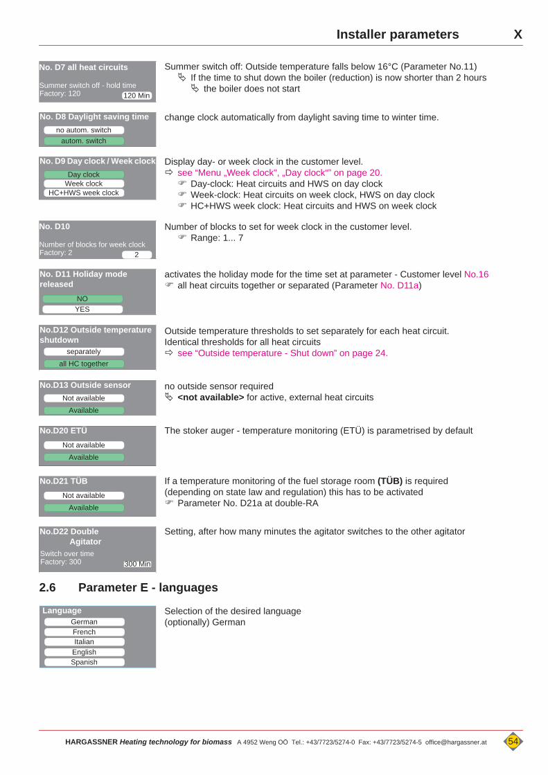
XInstaller parameters
Summer switch off: Outside temperature falls below 16°C (Parameter No.11) If the time to shut down the boiler (reduction) is now shorter than 2 hours the boiler does not start
change clock automatically from daylight saving time to winter time.
Display day- or week clock in the customer level. see “Menu „Week clock", „Day clock“” on page 20. Day-clock: Heat circuits and HWS on day clock Week-clock: Heat circuits on week clock, HWS on day clock HC+HWS week clock: Heat circuits and HWS on week clock
Number of blocks to set for week clock in the customer level. Range: 1... 7
activates the holiday mode for the time set at parameter - Customer level No.16 all heat circuits together or separated (Parameter No. D11a)
Outside temperature thresholds to set separately for each heat circuit.Identical thresholds for all heat circuits see “Outside temperature - Shut down” on page 24.
no outside sensor required <not available> for active, external heat circuits
The stoker auger - temperature monitoring (ETÜ) is parametrised by default
If a temperature monitoring of the fuel storage room (TÜB) is required (depending on state law and regulation) this has to be activated Parameter No. D21a at double-RA
Setting, after how many minutes the agitator switches to the other agitator
2.6 Parameter E - languages
Selection of the desired language(optionally) German
120 Min
No. D7 all heat circuits
Summer switch off - hold timeFactory: 120
no autom. switch
No. D8 Daylight saving time
autom. switch
Day clock
No. D9 Day clock / Week clock
Week clockHC+HWS week clock
2
No. D10
Number of blocks for week clockFactory: 2
No. D11 Holiday mode released
YESNO
separately
No.D12 Outside temperature shutdown
all HC together
Not available
No.D13 Outside sensor
Available
Not available
No.D20 ETÜ
Available
Not available
No.D21 TÜB
Available
No.D22 DoubleAgitator
300 MinSwitch over timeFactory: 300
German Language
FrenchItalian
EnglishSpanish
HARGASSNER Heating technology for biomass A 4952 Weng OÖ Tel.: +43/7723/5274-0 Fax: +43/7723/5274-5 [email protected] 54
X ParametersParameters X
3 Parameter list - CustomerReset to factory settings:<Settings> - <Service level> - <Special feat.> - <No. Z4 Load factory settings>
Menu Description Factory Is IsExtension module 0
No.1 HWS 1 Day clock ON 17:00 00:00OFF 20:00 00:00
to parametrise "Week clock" (menu no. D9 in installer settings)
No.1a HWS 1
Mo Tu We Th Fr Sa So ON 17:00 00:00 OFF 20:00 00:00
No.1b HWS 1 all offNo.2 HWS 1 Set temperature 60°
No. 2a HWS 1 circulation pump ON 17:00 00:00 OFF 20:00 00:00
No.3 Heat circuit 1 Day clock ON 06:00 15:00OFF 09:00 22:00
to parametrise "Week clock" (menu no. D9 in installer settings)
No.3a Heat circuit 1Mo Tu We Th Fr Sa ... ON 06:00 15:00 OFF 09:00 22:00
No.3b Heat circuit 1.........................SoON 06:00 00:00OFF 22:00 00:00
No.4 Heat circuit 1 Day-room temp. 20° CNo.5 Heat circuit 1 Reduction-room temp. 16° C
No.6 Heat circuit 2 Day clock ON 06:00 15:00OFF 09:00 22:00
to parametrise "Week clock" (menu no. D9 in installer settings)
No.6a Heat circuit 2 Mo Tu We Th Fr Sa So ON 06:00 15:00OFF 09:00 22:00
No.6b Heat circuit 2........................Su ON 06:00 00:00OFF 22:00 00:00
No.7 Heat circuit 2 Day-room temp. 20° CNo.8 Heat circuit 2 Reduction-room temp. 16° C
Heat circuit board A
HP 1 HWS A day clock ON 17:00 00:00OFF 20:00 00:00
HP 2 HWS A Set temperature 60°
HP 3 HWS A Day clock ON 06:00 15:00OFF 09:00 22:00
HP 4 Heat circuit A Day-room temp. 20°HP 5 Heat circuit A Reduction-room temp. 16°
Extension module 1
H 1 HWS 2 Day clock ON 17:00 00:00OFF 20:00 00:00
H 2 HWS 2 Set temperature 60°
H 3 Heat circuit 3 Day clock ON 06:00 15:00OFF 09:00 22:00
H 4 Heat circuit 3 Day-room temp. 20°H 5 Heat circuit 3 Reduction-room temp. 16°
H 6 Heat circuit 4 Day clock ON 06:00 15:00OFF 09:00 22:00
H 7 Heat circuit 4 Day-room temp. 20°H 8 Heat circuit 4 Reduction-room temp. 16°
55 HARGASSNER Heating technology for biomass A 4952 Weng OÖ Tel.: +43/7723/5274-0 Fax: +43/7723/5274-5 [email protected]

XParameters
Extension module 2
H 11 HWS 3 Day clock ON 17:00 00:00OFF 20:00 00:00
H 12 HWS 3 Set temperature 60°
H 13 Heat circuit 5 Day clock ON 06:00 15:00OFF 09:00 22:00
H 14 Heat circuit 5 Day-room temp. 20°H 15 Heat circuit 5 Reduction-room temp. 16°
H 16 Heat circuit 6 Day clock ON 06:00 15:00OFF 09:00 22:00
H 17 Heat circuit 6 Day-room temp. 20°H 18 Heat circuit 6 Reduction-room temp. 16°
If "Outside temperature shut down - separated" is chosen (Installer level No. D12), different temperatures per heat circuit may be set.No. 11 Heating off at outside temperature over 16°No. 12 Heating off at day reduct. outside temp. over 8°No. 13 Heating off at day reduct. outside temp. over -5°Through parametrisation "Outside temp. Day/N." (Service level No. M10) also for external heat circuits, outside temp. shut down may be set.No. 15 Holiday mode not activeNo. 16 Holiday mode from... - to...No. 18 Ash suction not activeNo. 19 Fuel Wood chipsNo. 19a Extraction system equal emptying
No. 20 Date / TimeNo. 21 Release remote maintenance not releasedNo. 21a autom. deactivation of release 10 Min.
HARGASSNER Heating technology for biomass A 4952 Weng OÖ Tel.: +43/7723/5274-0 Fax: +43/7723/5274-5 [email protected] 56

X Parameters
4 Parameter list - InstallerInstaller-settings (Settings / Installer / Code33)
Menu Description Factory Is Menu Description Factory Is
Hea
t circ
uit 1
A 1 Heat circuit 1 not avail.
Hea
t circ
uit 4
A 31 Heat circuit 4 not avail.A 2 HC 1 steepness 1.60 A 32 HC 4 steepness 1.60A 3 HC 1 flow temp. Min 30° A 33 HC 4 flow temp. Min 30°A 4 HC 1 flow temp. Max. 70° A 34 HC 4 flow temp. Max. 70°A 5 HC 1 mixer run time 90s A 35 HC 4 mixer run time 90sA 6 Remote HC1 not avail. A 36 Remote HC4 not avail.A 7 HC1 district line no dl A 37 HC4 district line no dlA 8 Summer-bath heating HC1 off A 38 Summer-bath heating HC4 offA 9 Screed hea. HC1 off A 39 Screed hea. HC4 off
A 9a Screed hea. HC1 Flow-rise 5°C A 39a - 39f Screed hea. Parameter HC4 acc. factory
set.
A 9b Screed hea. HC 1 Flow-set reduction 10°C
Hea
t circ
uit 5
A 41 Heat circuit 5 not avail.
A 9c Screed hea. HC1 rise after 1 day(s) A 42 HC 5 steepness 1.60A 9d Screed hea. HC1 Flow-Min. 20°C A 43 HC 5 flow temp. Min 30°A 9e Screed hea. HC1 Flow-Max. 45°C A 44 HC 5 flow temp. Max. 70°A 9f Screed hea. HC1 hold time 4 day(s) A 45 HC 5 mixer run time 90s
Hea
t circ
uit 2
A 11 Heat circuit 2 not avail. A 46 Remote HC5 not avail.A 12 HC 2 steepness 1.60 A 47 HC5 district line no dlA 13 HC 2 flow temp. Min 30° A 48 Summer-bath heating HC5 offA 14 HC 2 flow temp. Max. 70° A 49 Screed hea. HC5 OFF
A 15 HC 2 mixer run time 90s A 49a - 49f Screed hea. Parameter HC5 acc. factory
set.A 16 Remote HC2 not avail.
Hea
t circ
uit 6
A 51 Heat circuit 6 not avail.A 17 HC2 district line no dl A 52 HC 6 steepness 1.60A 18 Summer-bath heating HC2 off A 53 HC 6 flow temp. Min 30°A 19 Screed hea. HC2 off A 54 HC 6 flow temp. Max. 70°
A 19a - 19f Screed hea. Parameter HC2 acc. factory
set. A 55 HC 6 mixer run time 90s
Hea
t circ
uit 3
A 21 Heat circuit 3 not avail. A 56 Remote HC6 not avail.A 22 HC 3 steepness 1.60 A 57 HC6 district line no dlA 23 HC 3 flow temp. Min 30° A 58 Summer-bath heating HC6 offA 24 HC 3 flow temp. Max. 70° A 59 Screed hea. HC 6 off
A 25 HC 3 mixer run time 90s A 59a - 59f Screed hea. Parameter HC6 acc. factory
set.A 26 Remote HC3 not avail.
Hea
t circ
uit A
A 61 Heat circuit A not avail.A 27 HC3 district line no dl A 62 HC A steepness 1.60A 28 Summer-bath heating HC3 off A 63 HC A flow temp. Min 30°A 29 Screed hea. HC3 off A 64 HC A flow temp. Max. 70°
A 29a - 29f Screed hea. Parameter HC3 acc. factory
set. A 65 HC A mixer run time 90s
A 66 Remote HC A not avail.A 67 HC A6 district line no dlA 68 Summer-bath heating HC A offA 69 Screed hea. HC A off
A 69a - 69f
Screed hea. Parameter HC A
acc. factory set.
57 HARGASSNER Heating technology for biomass A 4952 Weng OÖ Tel.: +43/7723/5274-0 Fax: +43/7723/5274-5 [email protected]
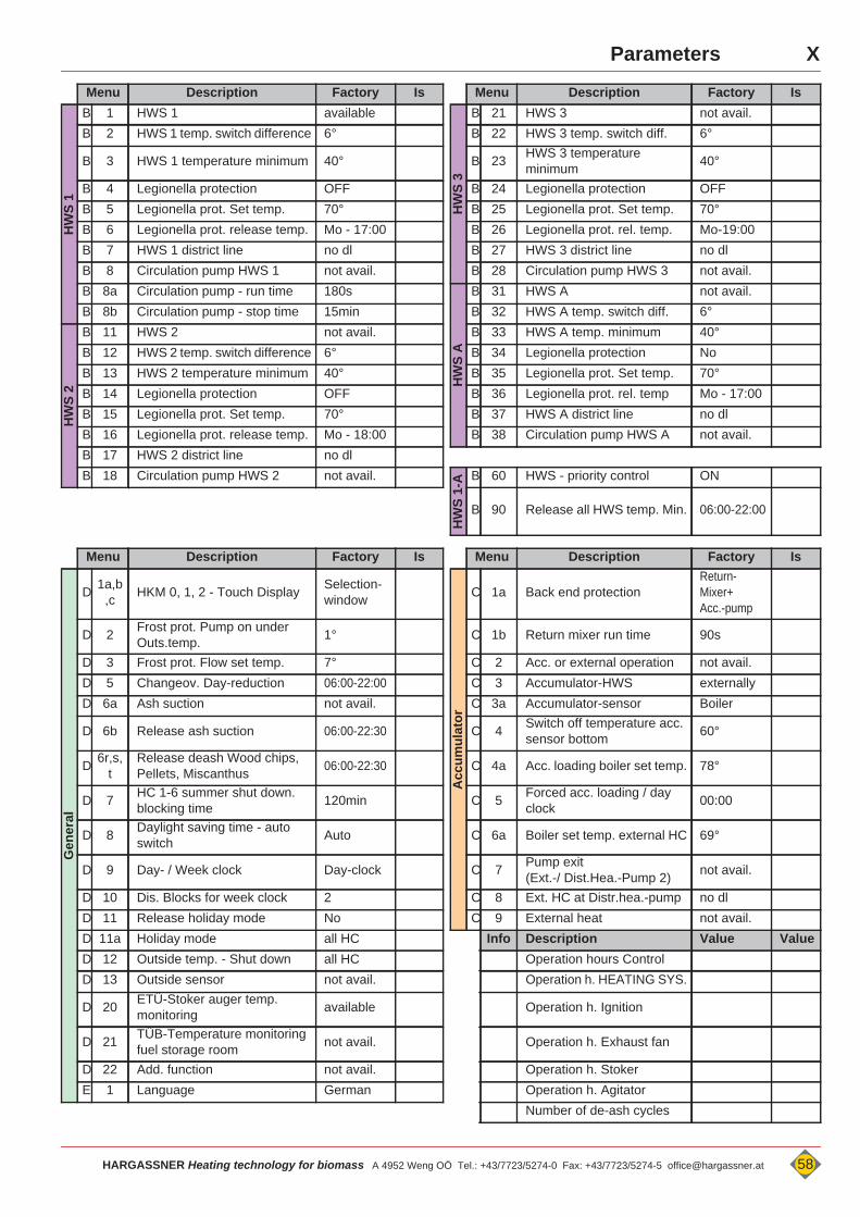
XParameters
Menu Description Factory Is Menu Description Factory Is
HW
S 1
B 1 HWS 1 available
HW
S 3
B 21 HWS 3 not avail.B 2 HWS 1 temp. switch difference 6° B 22 HWS 3 temp. switch diff. 6°
B 3 HWS 1 temperature minimum 40° B 23 HWS 3 temperature minimum 40°
B 4 Legionella protection OFF B 24 Legionella protection OFFB 5 Legionella prot. Set temp. 70° B 25 Legionella prot. Set temp. 70°B 6 Legionella prot. release temp. Mo - 17:00 B 26 Legionella prot. rel. temp. Mo-19:00B 7 HWS 1 district line no dl B 27 HWS 3 district line no dlB 8 Circulation pump HWS 1 not avail. B 28 Circulation pump HWS 3 not avail.B 8a Circulation pump - run time 180s
HW
S A
B 31 HWS A not avail.B 8b Circulation pump - stop time 15min B 32 HWS A temp. switch diff. 6°
HW
S 2
B 11 HWS 2 not avail. B 33 HWS A temp. minimum 40°B 12 HWS 2 temp. switch difference 6° B 34 Legionella protection NoB 13 HWS 2 temperature minimum 40° B 35 Legionella prot. Set temp. 70°B 14 Legionella protection OFF B 36 Legionella prot. rel. temp Mo - 17:00B 15 Legionella prot. Set temp. 70° B 37 HWS A district line no dlB 16 Legionella prot. release temp. Mo - 18:00 B 38 Circulation pump HWS A not avail.B 17 HWS 2 district line no dlB 18 Circulation pump HWS 2 not avail.
HW
S 1-
A B 60 HWS - priority control ON
B 90 Release all HWS temp. Min. 06:00-22:00
Menu Description Factory Is Menu Description Factory Is
Gen
eral
D 1a,b,c HKM 0, 1, 2 - Touch Display Selection-
window
Acc
umul
ator
C 1a Back end protection Return-Mixer+Acc.-pump
D 2 Frost prot. Pump on under Outs.temp. 1° C 1b Return mixer run time 90s
D 3 Frost prot. Flow set temp. 7° C 2 Acc. or external operation not avail.D 5 Changeov. Day-reduction 06:00-22:00 C 3 Accumulator-HWS externallyD 6a Ash suction not avail. C 3a Accumulator-sensor Boiler
D 6b Release ash suction 06:00-22:30 C 4 Switch off temperature acc. sensor bottom 60°
D 6r,s,t
Release deash Wood chips, Pellets, Miscanthus 06:00-22:30 C 4a Acc. loading boiler set temp. 78°
D 7 HC 1-6 summer shut down. blocking time 120min C 5 Forced acc. loading / day
clock 00:00
D 8 Daylight saving time - auto switch Auto C 6a Boiler set temp. external HC 69°
D 9 Day- / Week clock Day-clock C 7 Pump exit(Ext.-/ Dist.Hea.-Pump 2) not avail.
D 10 Dis. Blocks for week clock 2 C 8 Ext. HC at Distr.hea.-pump no dlD 11 Release holiday mode No C 9 External heat not avail.D 11a Holiday mode all HC Info Description Value ValueD 12 Outside temp. - Shut down all HC Operation hours ControlD 13 Outside sensor not avail. Operation h. HEATING SYS.
D 20 ETÜ-Stoker auger temp. monitoring available Operation h. Ignition
D 21 TÜB-Temperature monitoring fuel storage room not avail. Operation h. Exhaust fan
D 22 Add. function not avail. Operation h. StokerE 1 Language German Operation h. Agitator
Number of de-ash cycles
HARGASSNER Heating technology for biomass A 4952 Weng OÖ Tel.: +43/7723/5274-0 Fax: +43/7723/5274-5 [email protected] 58
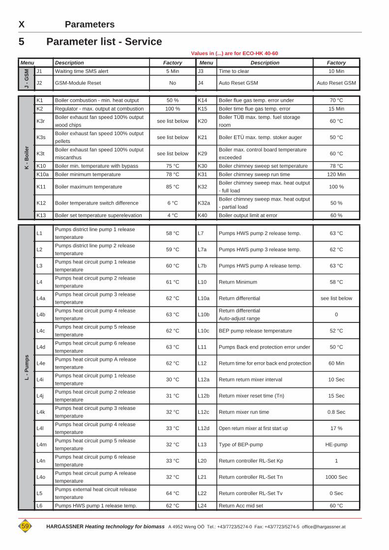
X Parameters
5 Parameter list - ServiceValues in (...) are for ECO-HK 40-60
Menu Description Factory Menu Description Factory
J - G
SM
J1 Waiting time SMS alert 5 Min J3 Time to clear 10 Min
J2 GSM-Module Reset No J4 Auto Reset GSM Auto Reset GSM
K -
Boi
ler
K1 Boiler combustion - min. heat output 50 % K14 Boiler flue gas temp. error under 70 °CK2 Regulator - max. output at combustion 100 % K15 Boiler time flue gas temp. error 15 Min
K3rBoiler exhaust fan speed 100% output wood chips
see list below K20Boiler TÜB max. temp. fuel storage room
60 °C
K3sBoiler exhaust fan speed 100% output pellets
see list below K21 Boiler ETÜ max. temp. stoker auger 50 °C
K3tBoiler exhaust fan speed 100% output miscanthus
see list below K29Boiler max. control board temperature exceeded
60 °C
K10 Boiler min. temperature with bypass 75 °C K30 Boiler chimney sweep set temperature 78 °CK10a Boiler minimum temperature 78 °C K31 Boiler chimney sweep run time 120 Min
K11 Boiler maximum temperature 85 °C K32Boiler chimney sweep max. heat output - full load
100 %
K12 Boiler temperature switch difference 6 °C K32aBoiler chimney sweep max. heat output - partial load
50 %
K13 Boiler set temperature superelevation 4 °C K40 Boiler output limit at error 60 %
L - P
umps
L1Pumps district line pump 1 release temperature
58 °C L7 Pumps HWS pump 2 release temp. 63 °C
L2Pumps district line pump 2 release temperature
59 °C L7a Pumps HWS pump 3 release temp. 62 °C
L3Pumps heat circuit pump 1 release temperature
60 °C L7b Pumps HWS pump A release temp. 63 °C
L4Pumps heat circuit pump 2 release temperature
61 °C L10 Return Minimum 58 °C
L4aPumps heat circuit pump 3 release temperature
62 °C L10a Return differential see list below
L4bPumps heat circuit pump 4 release temperature
63 °C L10bReturn differentialAuto-adjust range
0
L4cPumps heat circuit pump 5 release temperature
62 °C L10c BEP pump release temperature 52 °C
L4dPumps heat circuit pump 6 release temperature
63 °C L11 Pumps Back end protection error under 50 °C
L4ePumps heat circuit pump A release temperature
62 °C L12 Return time for error back end protection 60 Min
L4iPumps heat circuit pump 1 release temperature
30 °C L12a Return return mixer interval 10 Sec
L4jPumps heat circuit pump 2 release temperature
31 °C L12b Return mixer reset time (Tn) 15 Sec
L4kPumps heat circuit pump 3 release temperature
32 °C L12c Return mixer run time 0.8 Sec
L4lPumps heat circuit pump 4 release temperature
33 °C L12d Open return mixer at first start up 17 %
L4mPumps heat circuit pump 5 release temperature
32 °C L13 Type of BEP-pump HE-pump
L4nPumps heat circuit pump 6 release temperature
33 °C L20 Return controller RL-Set Kp 1
L4oPumps heat circuit pump A release temperature
32 °C L21 Return controller RL-Set Tn 1000 Sec
L5Pumps external heat circuit release temperature
64 °C L22 Return controller RL-Set Tv 0 Sec
L6 Pumps HWS pump 1 release temp. 62 °C L24 Return Acc mid set 60 °C
59 HARGASSNER Heating technology for biomass A 4952 Weng OÖ Tel.: +43/7723/5274-0 Fax: +43/7723/5274-5 [email protected]
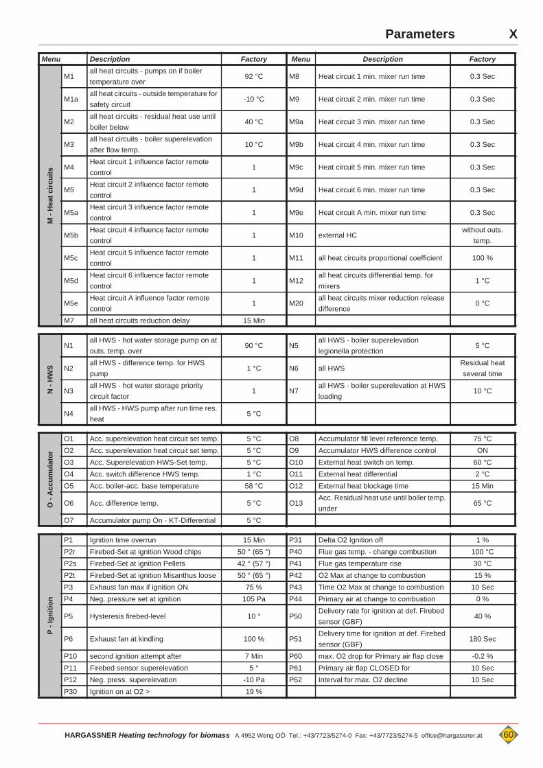
XParameters
Menu Description Factory Menu Description FactoryM
- H
eat c
ircui
ts
M1all heat circuits - pumps on if boiler temperature over
92 °C M8 Heat circuit 1 min. mixer run time 0.3 Sec
M1aall heat circuits - outside temperature for safety circuit
-10 °C M9 Heat circuit 2 min. mixer run time 0.3 Sec
M2all heat circuits - residual heat use until boiler below
40 °C M9a Heat circuit 3 min. mixer run time 0.3 Sec
M3all heat circuits - boiler superelevation after flow temp.
10 °C M9b Heat circuit 4 min. mixer run time 0.3 Sec
M4Heat circuit 1 influence factor remote control
1 M9c Heat circuit 5 min. mixer run time 0.3 Sec
M5Heat circuit 2 influence factor remote control
1 M9d Heat circuit 6 min. mixer run time 0.3 Sec
M5aHeat circuit 3 influence factor remote control
1 M9e Heat circuit A min. mixer run time 0.3 Sec
M5bHeat circuit 4 influence factor remote control
1 M10 external HCwithout outs.
temp.
M5cHeat circuit 5 influence factor remote control
1 M11 all heat circuits proportional coefficient 100 %
M5dHeat circuit 6 influence factor remote control
1 M12all heat circuits differential temp. for mixers
1 °C
M5eHeat circuit A influence factor remote control
1 M20all heat circuits mixer reduction release difference
0 °C
M7 all heat circuits reduction delay 15 Min
N -
HW
S
N1all HWS - hot water storage pump on at outs. temp. over
90 °C N5all HWS - boiler superelevation legionella protection
5 °C
N2all HWS - difference temp. for HWS pump
1 °C N6 all HWSResidual heat several time
N3all HWS - hot water storage priority circuit factor
1 N7all HWS - boiler superelevation at HWS loading
10 °C
N4all HWS - HWS pump after run time res. heat
5 °C
O -
Acc
umul
ator
O1 Acc. superelevation heat circuit set temp. 5 °C O8 Accumulator fill level reference temp. 75 °CO2 Acc. superelevation heat circuit set temp. 5 °C O9 Accumulator HWS difference control ONO3 Acc. Superelevation HWS-Set temp. 5 °C O10 External heat switch on temp. 60 °CO4 Acc. switch difference HWS temp. 1 °C O11 External heat differential 2 °CO5 Acc. boiler-acc. base temperature 58 °C O12 External heat blockage time 15 Min
O6 Acc. difference temp. 5 °C O13Acc. Residual heat use until boiler temp. under
65 °C
O7 Accumulator pump On - KT-Differential 5 °C
P - I
gniti
on
P1 Ignition time overrun 15 Min P31 Delta O2 Ignition off 1 %P2r Firebed-Set at ignition Wood chips 50 ° (65 °) P40 Flue gas temp. - change combustion 100 °CP2s Firebed-Set at ignition Pellets 42 ° (57 °) P41 Flue gas temperature rise 30 °CP2t Firebed-Set at ignition Misanthus loose 50 ° (65 °) P42 O2 Max at change to combustion 15 %P3 Exhaust fan max if ignition ON 75 % P43 Time O2 Max at change to combustion 10 SecP4 Neg. pressure set at ignition 105 Pa P44 Primary air at change to combustion 0 %
P5 Hysteresis firebed-level 10 ° P50Delivery rate for ignition at def. Firebed sensor (GBF)
40 %
P6 Exhaust fan at kindling 100 % P51Delivery time for ignition at def. Firebed sensor (GBF)
180 Sec
P10 second ignition attempt after 7 Min P60 max. O2 drop for Primary air flap close -0.2 %P11 Firebed sensor superelevation 5 ° P61 Primary air flap CLOSED for 10 SecP12 Neg. press. superelevation -10 Pa P62 Interval for max. O2 decline 10 SecP30 Ignition on at O2 > 19 %
HARGASSNER Heating technology for biomass A 4952 Weng OÖ Tel.: +43/7723/5274-0 Fax: +43/7723/5274-5 [email protected] 60
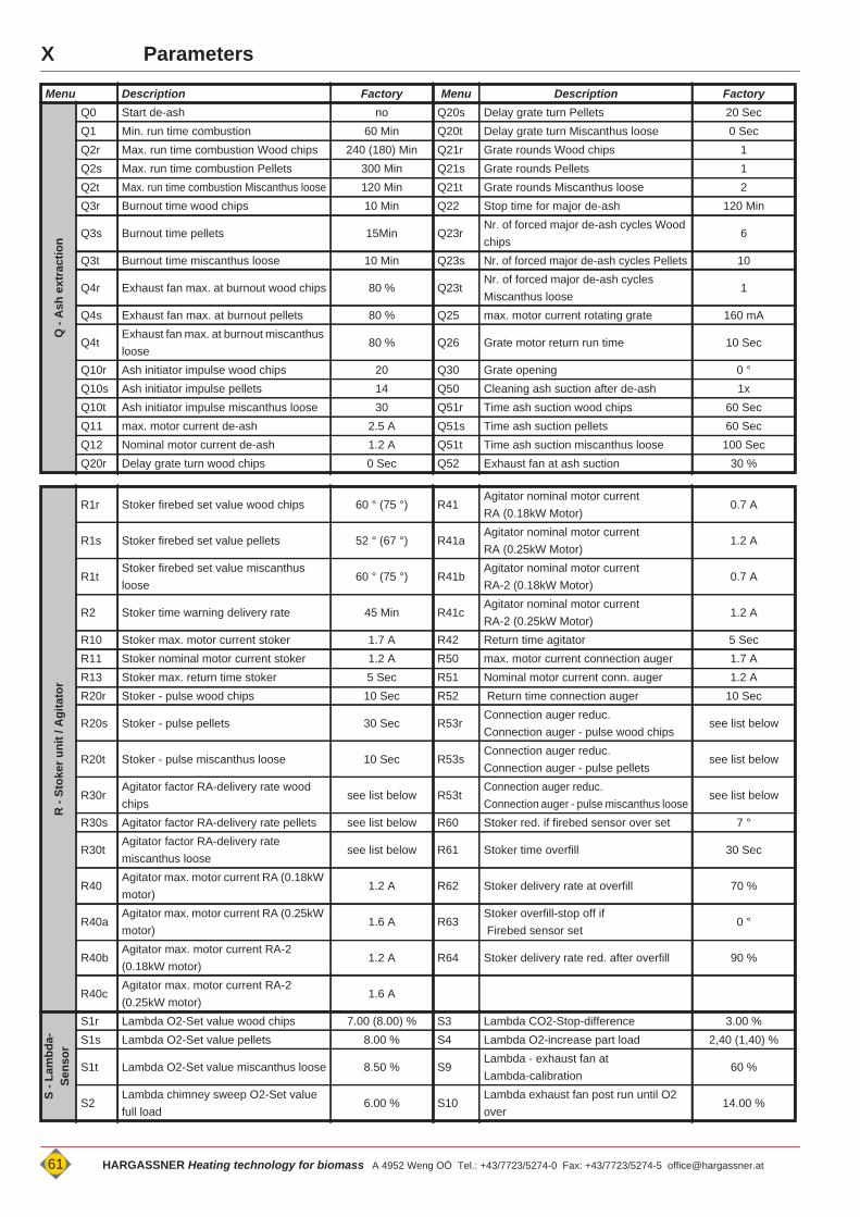
X Parameters
Menu Description Factory Menu Description Factory
Q -
Ash
ext
ract
ion
Q0 Start de-ash no Q20s Delay grate turn Pellets 20 SecQ1 Min. run time combustion 60 Min Q20t Delay grate turn Miscanthus loose 0 SecQ2r Max. run time combustion Wood chips 240 (180) Min Q21r Grate rounds Wood chips 1Q2s Max. run time combustion Pellets 300 Min Q21s Grate rounds Pellets 1Q2t Max. run time combustion Miscanthus loose 120 Min Q21t Grate rounds Miscanthus loose 2Q3r Burnout time wood chips 10 Min Q22 Stop time for major de-ash 120 Min
Q3s Burnout time pellets 15Min Q23rNr. of forced major de-ash cycles Wood chips
6
Q3t Burnout time miscanthus loose 10 Min Q23s Nr. of forced major de-ash cycles Pellets 10
Q4r Exhaust fan max. at burnout wood chips 80 % Q23tNr. of forced major de-ash cycles Miscanthus loose
1
Q4s Exhaust fan max. at burnout pellets 80 % Q25 max. motor current rotating grate 160 mA
Q4tExhaust fan max. at burnout miscanthus loose
80 % Q26 Grate motor return run time 10 Sec
Q10r Ash initiator impulse wood chips 20 Q30 Grate opening 0 °Q10s Ash initiator impulse pellets 14 Q50 Cleaning ash suction after de-ash 1xQ10t Ash initiator impulse miscanthus loose 30 Q51r Time ash suction wood chips 60 SecQ11 max. motor current de-ash 2.5 A Q51s Time ash suction pellets 60 SecQ12 Nominal motor current de-ash 1.2 A Q51t Time ash suction miscanthus loose 100 SecQ20r Delay grate turn wood chips 0 Sec Q52 Exhaust fan at ash suction 30 %
R -
Stok
er u
nit /
Agi
tato
r
R1r Stoker firebed set value wood chips 60 ° (75 °) R41Agitator nominal motor currentRA (0.18kW Motor)
0.7 A
R1s Stoker firebed set value pellets 52 ° (67 °) R41aAgitator nominal motor currentRA (0.25kW Motor)
1.2 A
R1tStoker firebed set value miscanthus loose
60 ° (75 °) R41bAgitator nominal motor currentRA-2 (0.18kW Motor)
0.7 A
R2 Stoker time warning delivery rate 45 Min R41cAgitator nominal motor currentRA-2 (0.25kW Motor)
1.2 A
R10 Stoker max. motor current stoker 1.7 A R42 Return time agitator 5 SecR11 Stoker nominal motor current stoker 1.2 A R50 max. motor current connection auger 1.7 AR13 Stoker max. return time stoker 5 Sec R51 Nominal motor current conn. auger 1.2 AR20r Stoker - pulse wood chips 10 Sec R52 Return time connection auger 10 Sec
R20s Stoker - pulse pellets 30 Sec R53rConnection auger reduc.Connection auger - pulse wood chips
see list below
R20t Stoker - pulse miscanthus loose 10 Sec R53sConnection auger reduc.Connection auger - pulse pellets
see list below
R30rAgitator factor RA-delivery rate wood chips
see list below R53tConnection auger reduc.Connection auger - pulse miscanthus loose
see list below
R30s Agitator factor RA-delivery rate pellets see list below R60 Stoker red. if firebed sensor over set 7 °
R30tAgitator factor RA-delivery rate miscanthus loose
see list below R61 Stoker time overfill 30 Sec
R40Agitator max. motor current RA (0.18kW motor)
1.2 A R62 Stoker delivery rate at overfill 70 %
R40aAgitator max. motor current RA (0.25kW motor)
1.6 A R63Stoker overfill-stop off if Firebed sensor set
0 °
R40bAgitator max. motor current RA-2 (0.18kW motor)
1.2 A R64 Stoker delivery rate red. after overfill 90 %
R40cAgitator max. motor current RA-2 (0.25kW motor)
1.6 A
S - L
ambd
a-Se
nsor
S1r Lambda O2-Set value wood chips 7.00 (8.00) % S3 Lambda CO2-Stop-difference 3.00 %S1s Lambda O2-Set value pellets 8.00 % S4 Lambda O2-increase part load 2,40 (1,40) %
S1t Lambda O2-Set value miscanthus loose 8.50 % S9Lambda - exhaust fan at Lambda-calibration
60 %
S2Lambda chimney sweep O2-Set value full load
6.00 % S10Lambda exhaust fan post run until O2 over
14.00 %
61 HARGASSNER Heating technology for biomass A 4952 Weng OÖ Tel.: +43/7723/5274-0 Fax: +43/7723/5274-5 [email protected]
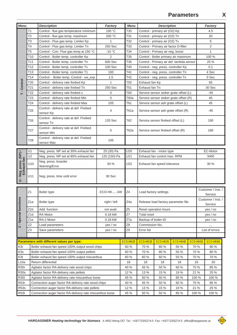
XParameters
Menu Description Factory Menu Description FactoryT
- Con
trol
T1 Control - flue gas temperature minimum 100 °C T30 Control - primary air (O2) Kp 4.5T2 Control - flue gas temp. maximum 200 °C T31 Control - primary air (O2) Tn 20T3 Control - Flue gas temp. Limiter Kp 1 T32 Control - primary air (O2) Tv 5T4 Control - Flue gas temp. Limiter Tn 250 Sec T33 Control - Primary air factor D-filter 2T5 Control - Corr. Flue gas temp at 150 °C -10 °C T34 Control - Primary air neg. boost 1T10 Control - Boiler temp. controller Kp 2 T35 Control - Boiler primary air maximum 100 %T11 Control - Boiler temp. controller Tn 600 Sec T36 Control - Primary air def. lambda sensor 25 %T12 Control - Boiler temp. controller Tv 100 Sec T40 Control - neg. press. controller Kp 0.1T13 Control - Boiler temp. controller T1 100 T41 Control - neg. press. controller Tn 4 SecT14 Control - Boiler temp. Control - xw_exp 1.5 T42 Control - neg. press. controller Tv 0 SecT20 Control - delivery rate firebed Kp 1 T50 Exhaust fan Kp 65T21 Control - delivery rate firebed Tn 250 Sec T51 Exhaust fan Tn 30 SecT22 Control - delivery rate firebed z 0 T60 Service sensor stoker grate offset (L) -45T23 Control - delivery rate firebed Min 0 T60a Service sensor stoker grate offset (R) 45T24 Control - delivery rate firebed Max 105 T61 Service sensor ash grate offset (L) 45
T25Control - delivery rate at def. Firebed sensor Kp
4 T61a Service sensor ash grate offset (R) -45
T26Control - delivery rate at def. Firebed sensor Tn
120 Sec T62 Service sensor firebed offset (L) 190
T27Control - delivery rate at def. Firebed sensor Min
0 T62a Service sensor firebed offset (R) 190
T28Control - delivery rate at def. Firebed sensor Max
105
U -
Neg
. pre
ss. (
NP)
/ Ex
haus
t fan
U1 Neg. press. NP set at 30% exhaust fan 25 (30) Pa U20 Exhaust fan - motor type EC-MotorU2 Neg. press. NP set at 80% exhaust fan 125 (150) Pa U21 Exhaust fan control max. RPM 3400
U10Neg. press. boarderWarning/Error
50 % U22 Exhaust fan speed tolerance 30 %
U11 Neg. press. time until error 30 Sec
Z - S
peci
al fu
nctio
ns
Z1 Boiler type ECO-HK......kW Z4 Load factory settingsCustomer / Inst. /
Service
Z1a Boiler type right / left Z4a Release load factory parameter fileCustomer / Inst. /
ServiceZ1b Add. function not avail. Z5 Reset operation hours yes / noZ1d RA Motor 0.18 kW Z7 Total reset yes / noZ1e RA-2 Motor 0.18 kW Z7a Backup of boiler-ID yes / noZ2 Load parameters yes / no Z8 Commission-No. ...Z3 Save parameters yes / no Z9 Error list List of errors
Parameters with different values per type: ECO-HK20 ECO-HK30 ECO-HK35 ECO-HK40 ECO-HK50 ECO-HK60K3r Boiler exhaust fan speed 100% output wood chips 60 % 70 % 80 % 55 % 70 % 80 %K3s Boiler exhaust fan speed 100% output pellets 60 % 70 % 80 % 55 % 70 % 80 %K3t Boiler exhaust fan speed 100% output miscanthus 60 % 60 % 60 % 55 % 70 % 70 %L10a Return differential 18 18 18 18 19 20R30r Agitator factor RA-delivery rate wood chips 40 % 45 % 50 % 60 % 70 % 85 %R30s Agitator factor RA-delivery rate pellets 12 % 13 % 15 % 19 % 21 % 25 %R30t Agitator factor RA-delivery rate miscanthus loose 45 % 50 % 50 % 85 % 100 % 100 %R53r Connection auger factor RA-delivery rate wood chips 40 % 45 % 50 % 60 % 70 % 85 %R53s Connection auger factor RA-delivery rate pellets 12 % 13 % 15 % 19 % 21 % 25 %R53t Connection auger factor RA-delivery rate miscanthus loose 45 % 50 % 50 % 85 % 100 % 100 %
HARGASSNER Heating technology for biomass A 4952 Weng OÖ Tel.: +43/7723/5274-0 Fax: +43/7723/5274-5 [email protected] 62
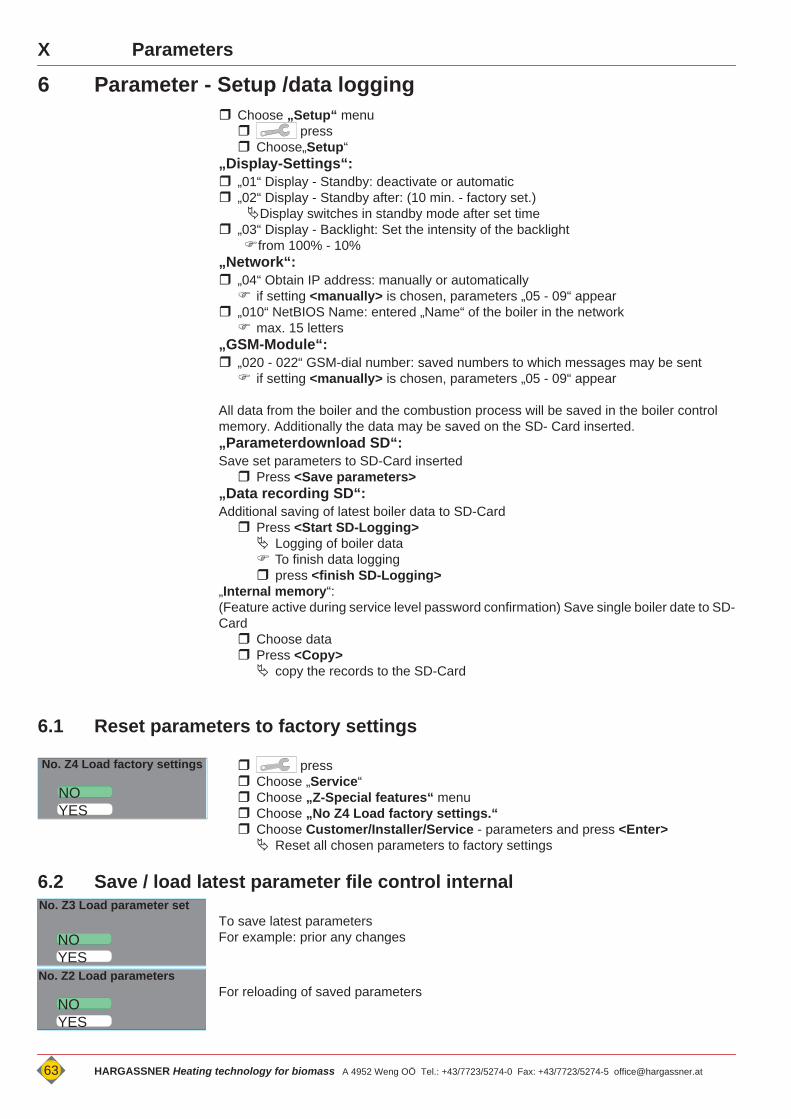
X Parameters
6 Parameter - Setup /data logging Choose „Setup“ menu press Choose„Setup“
„Display-Settings“: „01“ Display - Standby: deactivate or automatic „02“ Display - Standby after: (10 min. - factory set.)
Display switches in standby mode after set time „03“ Display - Backlight: Set the intensity of the backlightfrom 100% - 10%
„Network“: „04“ Obtain IP address: manually or automatically if setting <manually> is chosen, parameters „05 - 09“ appear
„010“ NetBIOS Name: entered „Name“ of the boiler in the network max. 15 letters
„GSM-Module“: „020 - 022“ GSM-dial number: saved numbers to which messages may be sent if setting <manually> is chosen, parameters „05 - 09“ appear
All data from the boiler and the combustion process will be saved in the boiler control memory. Additionally the data may be saved on the SD- Card inserted.„Parameterdownload SD“:Save set parameters to SD-Card inserted Press <Save parameters>
„Data recording SD“:Additional saving of latest boiler data to SD-Card Press <Start SD-Logging> Logging of boiler data To finish data logging press <finish SD-Logging>
„Internal memory“:(Feature active during service level password confirmation) Save single boiler date to SD-Card Choose data Press <Copy> copy the records to the SD-Card
6.1 Reset parameters to factory settings
press Choose „Service“ Choose „Z-Special features“ menu Choose „No Z4 Load factory settings.“ Choose Customer/Installer/Service - parameters and press <Enter> Reset all chosen parameters to factory settings
6.2 Save / load latest parameter file control internal
To save latest parametersFor example: prior any changes
For reloading of saved parameters
NO
No. Z4 Load factory settings
YES
NO
No. Z3 Load parameter set
YES
NO
No. Z2 Load parameters
YES
63 HARGASSNER Heating technology for biomass A 4952 Weng OÖ Tel.: +43/7723/5274-0 Fax: +43/7723/5274-5 [email protected]
XI
HARGASSNER Heating technology for Biomass A 4952 Weng OÖ Tel.: +43/7723/5274-0 Fax: +43/7723/5274-5 [email protected] 64
Appendix
Chapter XI: Appendix
7 Copyright noticeThis manual should be kept confidential. The manual is intended solely to be used by authorised persons.The transfer to third parties is prohibited and is liable to compensation. All rights reserved, also translations.No part of this manual may be reproduced or processed using electronic systems, duplicated or distributed without permission of Hargassner GmbH.
7.1 Special measures prior commissioning through the operatorLicensing requirements for safe operation and accident prevention regulations must be observed!
7.2 LiabilityThe AUTOMATIC BIOMASS BOILER is a state-of-the-art product and manufactured and tested according to recognised safety regulations. However, improper use may cause lethal hazards for the operator or third parties or may damage the unit and other property.
The AUTOMATIC BIOMASS BOILER must only be operated as intended and in technically perfect condition! Especially, errors tending to affect the safety shall be cleared immediately!
The liability for the function of the AUTOMATIC BIOMASS BOILER must be borne by the owner or user, if the device has been used by persons without the necessary knowledge from Hargassner GmbH , the device has been improperly used, serviced or repaired or has been handled in a manner that does not conform to proper use.In the interest of the continuous development and improvement of our products, we reserve all rights to make technical changes to the in-formation contained in our printed material. Changes, errors and printer's errors do not justify claims for damages.Only Original- Hargassner- spare parts must be used. In addition to the guidelines in this operation manual, please follow general guidelines for safety and accident prevention. The AUTOMATIC BIOMASS BOILER must at least 15 minutes prior be separated from the mains prior any maintenance works on the boiler (Service, unscrew covers, etc.) Hargassner GmbH shall not be liable for direct or consequential damage resulting from failure to observe the technical instruc-tions, guidelines and recommendations. The vast experience of latest production technology and highest quality standards from Hargassner GmbH guarantee the reliability of this boiler system. Hargassner GmbH can under no circumstances be held liable for improper operation of the product, for damage to the product itself or for consequential damage caused by the product if the damage has been caused by incorrect use or handling of the product.The customer has NO warranty claims:
• if heating fuel is missing wrong or of poor quality• if damages occur through incorrect assembly, misuse or lack of maintenance• if the installation manual and operation manual is NOT observed• for defects that do not affect the performance of the system. E.g.: Paint defects,.... • for damages arising from force majeure like fire, flooding, lightning stroke, electrical surge, power
loss, ...• if a non-licensed installer or non-licensed plumber installs the product• for damages arising through air pollution, very dusty surrounding, aggressive vapours, corrosion
through oxygen (non diffusion-resistant plastic tubing), installation in inappropriate rooms (laundry room, ....) or through further use, even though a defect has been recognised.
For the correct reparation, maintenance and service, or any other error not mentioned in this manual, Hargassner GmbH has to be contacted prior any works on the plant.Warranty and liability of the general terms and conditions of Hargassner GmbH are not to be extended because of hints pointed out in this manual.The safety instructions in this manual must be observed. Only use Hargassner GmbH - spare parts or Hargassner GmbH released, equiv-alent spare parts. Constant technical innovations mean that we reserve the right to modify the design of our products and services without notice.For any questions always prepare the Hargassner Boiler number .
We wish you the best with your BIOMASS BOILER.
n o t i c e
Please be advised that we are not responsible for damages or malfunctions resulting from non-observance of the operation manual.
XI


