
International Journal on Electrical Engineering and Informatics - Volume 8, Number 4, December 2016
Implementation of Field Oriented Speed Sensorless
Control of Induction Motor Drive
R. Gunabalan1 and V. Subbiah
2
1School of Electrical and Electronics Engineering, VIT University, Chennai,
TamilNadu, INDIA 2Department of Electrical and Electronics Engineering, PSG College of Technology,
Coimbatore, TamilNadu, INDIA
Abstract: This paper focuses the hardware realization and implementation of speed-sensorless
field oriented control of induction motor drive. For speed sensorless operation, natural observer
is applied to estimate the stator currents, rotor fluxes, load torque and rotor speed because of its
simple structure and no direct feedback. The configuration of the natural observer is
comparable to and as well as its feature is identical to the induction motor. State space model is
applied to both the estimator and the induction motor. Load torque adaptation is provided to
estimate the load torque and, speed is estimated from the torque, rotor fluxes and stator
currents. Direct field oriented sensorless vector control scheme is used and the rotor angle is
calculated from the estimated rotor fluxes. Simulations as well as experimental results are
presented for various speed and load conditions to demonstrate the performance of natural
observer in sensorless vector control applications.
Keywords: Induction motor, DSP processor, observer, sensorless control, simulation
1. Introduction
Induction motors are favoured for very large drives because of the boundaries of
commutation and rotor speed in dc drives. The induction motor is in fact 'brushless' and can
work with simple controls without a shaft position transducer. Induction motor control can be
classified into two types: scalar control and vector control.
In scalar control [1], the magnitude of the control variable is varied and it disregards the
coupling effect in the machine. The most popular method is V/f control, which adjusts the
constant volt per hertz of the stator voltage to keep the stator flux constant. The dynamic
performance of V/f control is unsatisfactory because of temperature and saturation effect.
Recent developments in fast switching power semiconductor devices and powerful digital
signal processors made advanced control techniques of induction motors.
The vector control is introduced in the beginning of 1970s. The vector control consists of
controlling the stator currents represented by a vector. This control is based on transforming a
three phase time and frequency dependent system into a two co-ordinate (d and q axes) time
invariant system. These projections lead to a structure similar to that of a separately excited dc
motor control.
Vector control is also called as Field Oriented Control (FOC). Generally, two types of field
oriented control schemes are available. 1. Direct field oriented control 2. Indirect field oriented
control. In the direct scheme, the instantaneous position of rotor flux (θe) has to be measured
using flux sensors. This adds to the cost and complexity of the drive system. In the indirect
scheme, a model of induction motor is required to calculate the reference angular slip
frequency that has to be added to the measured rotor speed. The sum is integrated to calculate
the instantaneous position of the rotor flux. Indirect field orientation is more sensitive to
parameters values inaccuracy than direct field orientation. The value of the rotor time constant
(Lr/R
r) is used in the slip frequency calculation and is sensitive to temperature and flux level.
The need of special position incremental encoder is another disadvantage of the method. To
avoid these complications, different algorithms are projected, to estimate both the rotor flux
Received: September 15th
, 2014. Accepted: November 8th
, 2016
DOI: 10.15676/ijeei.2016.8.4.2
727
vector and/or rotor shaft speed. The induction motor drives without mechanical speed sensors
have the attractions of low cost, high reliability and reduce the size and the lack of additional
wiring for sensors or devices mounted on the shaft. Nowadays, a number of adaptive observer
design techniques are available for speed and flux estimation. The standard speed estimators
are Luenberger observer [2] – [7], Extended Kalman Filter (EKF) [8] – [13], Model Reference
Adaptive System (MRAS) [14] – [18], natural observer [19], load torque observer [20]-[21],
sliding mode observer [22] – [23] etc.
The selection of the observer gain constant (K) is difficult in Luenberger observer. The
initial selection of noise covariance matrices is not easy in EKF and subsequently the algorithm
is complicated. The number of inputs in EKF and Luenberger observer is different to the
number of inputs to the induction motor since they utilize output feedback. The above
difficulties are overcome by introducing natural observer for estimating the speed and also the
load torque.
The paper is organized as follows: Chapter 2 discusses the concepts of natural observer.
The simulation results are presented in chapter 3. Hardware circuits and results are presented in
chapter 4 and are concluded in chapter 5.
2. Mathematical Model of Natural Observer
The structure and features of the natural observer are identical to the induction motor for
the given supply voltage and load torque. The major difference between natural and
conventional observer is that there is no external feedback and faster convergence rate. As a
result, the speed estimation follows the speed changes simultaneously. Its dynamic behavior is
exactly the same as the motor and load torque adaptation is used to estimate the load torque
from the active power error. Fourth order induction motor model in stator flux oriented
reference frame is used to estimate the speed, where dq-axes stator currents and rotor fluxes are
selected as state variables. The induction motor is represented in stationary reference frame by
the following state equations:
𝑑𝑋
𝑑𝑡= 𝐴𝑋 + 𝐵𝑉𝑠 (1)
𝑌 = 𝐶𝑋 (2)
where,
𝐴 =
[ −(Rs+Rr(
LmLr
)2)
σLs0
Lm
σLsLrτr
ωrLm
σLsLr
0−(Rs+Rr(
LmLr
)2)
σLs
−ωrLm
σLsLr
Lm
σLsLrτr
Lm
τr0
−1
τr−ωr
0Lm
τrωr
−1
τr ]
𝐵 =
[
1
𝜎𝐿𝑠
0
01
𝜎𝐿𝑠
0 00 0 ]
𝐶 = [1 0 0 00 1 0 0
]
σ = 1 −𝐿𝑚2
𝐿𝑠𝐿𝑟 - leakage coefficient
𝑋 = [𝑖𝑑𝑠𝑠 𝑖𝑞𝑠
𝑠 𝜑𝑑𝑟𝑠 𝜑𝑞𝑟
𝑠 ]𝑇
𝑌 = [𝑖𝑑𝑠𝑠 𝑖𝑞𝑠
𝑠 ] = 𝑖𝑠
𝑉𝑠 = [𝑉𝑑𝑠𝑠 𝑉𝑞𝑠
𝑠 ]𝑇
R. Gunabalan, et al.
728
Ls, Lr – stator and rotor self inductance respectively (H)
Lm- mutual inductance (H)
𝜏𝑟-rotor time constant =Lr
Rr
r -motor angular velocity (rad/s)
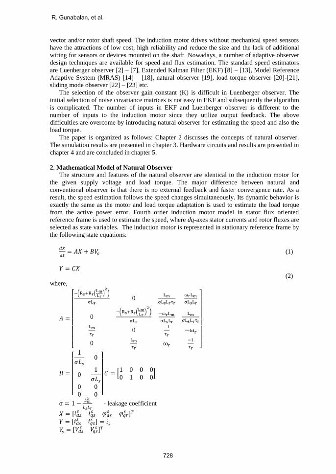
The block diagram representation of natural observer is shown in Figure 1 and the observer
state equations are as follows:
𝑑
𝑑𝑡= + 𝐵𝑉𝑠 (3)
= 𝐶 (4)
= [𝑖𝑑𝑠𝑠 𝑖𝑞𝑠
𝑠 𝑑𝑟𝑠 𝑞𝑟
𝑠 ]𝑇
= [𝑖𝑑𝑠𝑠 𝑖𝑞𝑠
𝑠 ]𝑇 = 𝑖𝑠
where, “^” represents the estimated quantities.
The load torque is estimated from the active power error by the following equation [14]:
TL = KPeP + KI ∫ eP dt (5)
𝑒𝑃 = 𝑉𝑑𝑠𝑠 (𝑖𝑑𝑠
𝑒 − 𝑖𝑑𝑠𝑒 ) + 𝑉𝑞𝑠
𝑠 (𝑖𝑞𝑠𝑒 − 𝑖𝑞𝑠
𝑒 ) (6)
Estimation of rotor speed is acquired from estimated stator current, rotor flux and the estimated
load torque as:
𝜔 = (3
2) (
𝑛𝑝
𝐽) (
𝐿𝑚
𝐿𝑟) [𝑑𝑟
𝑠 𝑖𝑞𝑠𝑠 − 𝑞𝑟
𝑠 𝑖𝑑𝑠𝑠 ] −
𝑇𝐿
𝐽
(7)
Where np is the no. of pole pairs and J is of inertia of motor load system (kg.m2). The speed
estimation methods in EKF and Luenberger observer always desires some correction term in
order to follow speed changes. This results in the estimation always lagging the actual values.
In natural observer, the speed estimation follows the speed changes simultaneously even for
sudden change occurs in the load torque.
Figure 1. Block diagram of a natural observer with load torque adaptation
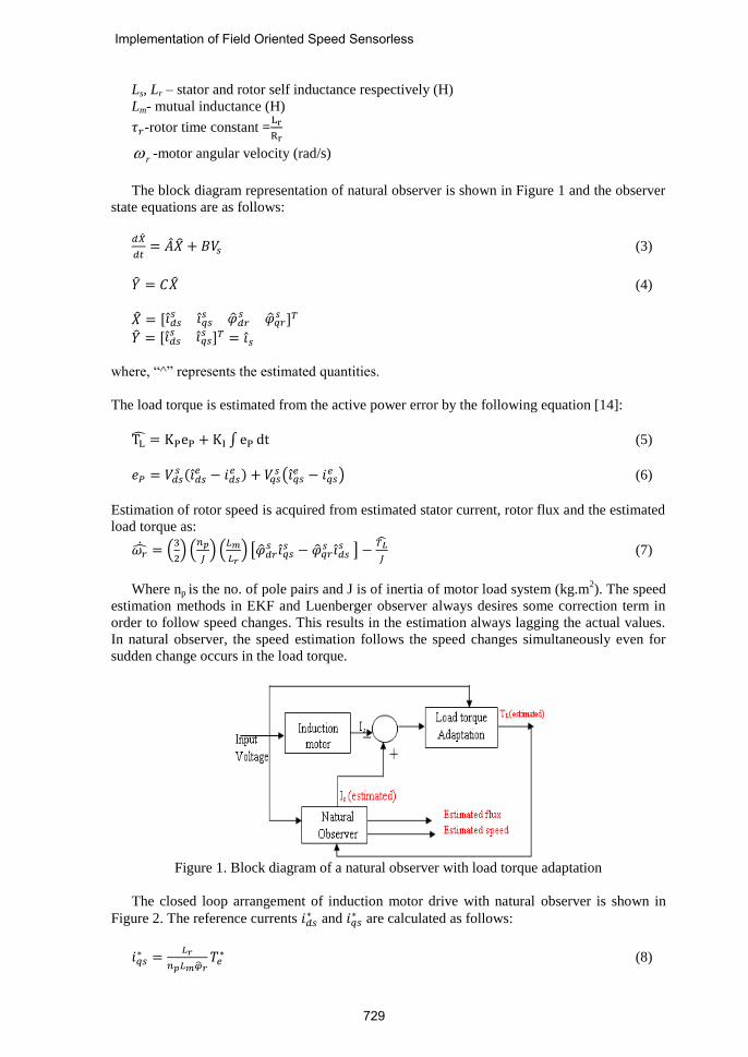
The closed loop arrangement of induction motor drive with natural observer is shown in
Figure 2. The reference currents 𝑖𝑑𝑠∗ and 𝑖𝑞𝑠
∗ are calculated as follows:
𝑖𝑞𝑠∗ =
𝐿𝑟
𝑛𝑝𝐿𝑚𝑟𝑇𝑒
∗ (8)
Implementation of Field Oriented Speed Sensorless
729
𝑖𝑑𝑠∗ is obtained by comparing the actual flux with the reference flux and the error is processed in
the PI controller which gives the desired value of 𝑖𝑑𝑠∗ . It is also attained by the following
equation for a known flux value.
𝑖𝑑𝑠∗ =
𝜑𝑑𝑟∗
𝐿𝑚 (9)
The reference currents are transformed into stationary reference frame by rotor angle 𝜃𝑒.
The two phase dq-axes stator currents are transformed into three phase reference currents by 2
to 3 conversion blocks (inverse Clarke’s transformation).
Figure 2. Closed loop arrangement of induction motor with natural observer
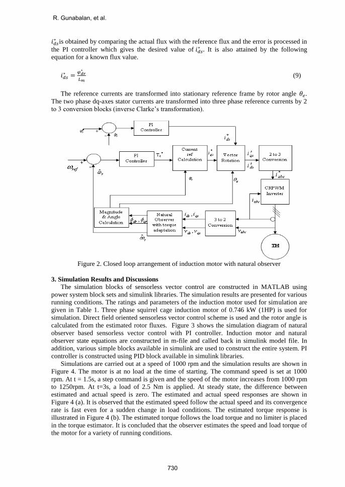
3. Simulation Results and Discussions
The simulation blocks of sensorless vector control are constructed in MATLAB using
power system block sets and simulink libraries. The simulation results are presented for various
running conditions. The ratings and parameters of the induction motor used for simulation are
given in Table 1. Three phase squirrel cage induction motor of 0.746 kW (1HP) is used for
simulation. Direct field oriented sensorless vector control scheme is used and the rotor angle is
calculated from the estimated rotor fluxes. Figure 3 shows the simulation diagram of natural
observer based sensorless vector control with PI controller. Induction motor and natural
observer state equations are constructed in m-file and called back in simulink model file. In
addition, various simple blocks available in simulink are used to construct the entire system. PI
controller is constructed using PID block available in simulink libraries.
Simulations are carried out at a speed of 1000 rpm and the simulation results are shown in
Figure 4. The motor is at no load at the time of starting. The command speed is set at 1000
rpm. At t = 1.5s, a step command is given and the speed of the motor increases from 1000 rpm
to 1250rpm. At t=3s, a load of 2.5 Nm is applied. At steady state, the difference between
estimated and actual speed is zero. The estimated and actual speed responses are shown in
Figure 4 (a). It is observed that the estimated speed follow the actual speed and its convergence
rate is fast even for a sudden change in load conditions. The estimated torque response is
illustrated in Figure 4 (b). The estimated torque follows the load torque and no limiter is placed
in the torque estimator. It is concluded that the observer estimates the speed and load torque of
the motor for a variety of running conditions.
R. Gunabalan, et al.
730
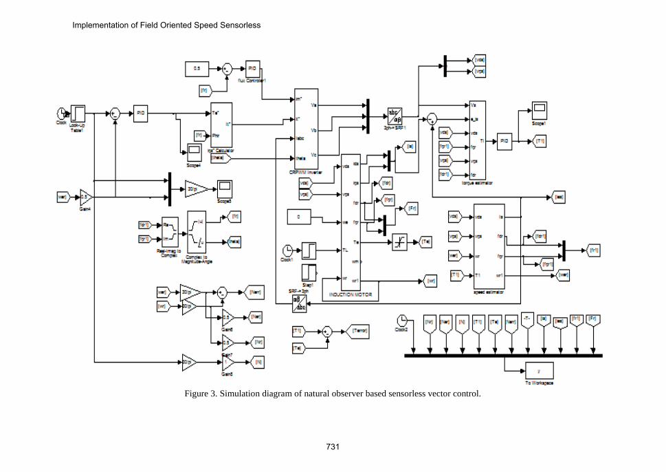
Figure 3. Simulation diagram of natural observer based sensorless vector control.
Implementation of Field Oriented Speed Sensorless
731
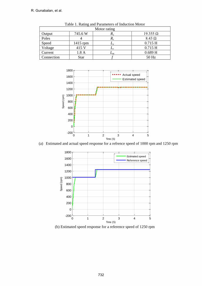
Table 1. Rating and Parameters of Induction Motor
Motor rating
Output 745.6 W Rs 19.355 Ω
Poles 4 Rr 8.43 Ω
Speed 1415 rpm Ls 0.715 H
Voltage 415 V Lr 0.715 H
Current 1.8 A Lm 0.689 H
Connection Star f 50 Hz
(a) Estimated and actual speed response for a refrence speed of 1000 rpm and 1250 rpm
(b) Estimated speed response for a reference speed of 1250 rpm
0 1 2 3 4 5-200
0
200
400
600
800
1000
1200
1400
1600
1800
Time (S)
Speed (
rpm
)
Actual speed
Estimated speed
0 1 2 3 4 5-200
0
200
400
600
800
1000
1200
1400
1600
1800
Time (S)
Speed (
rpm
)
Estimated speed
Reference speed
R. Gunabalan, et al.
732
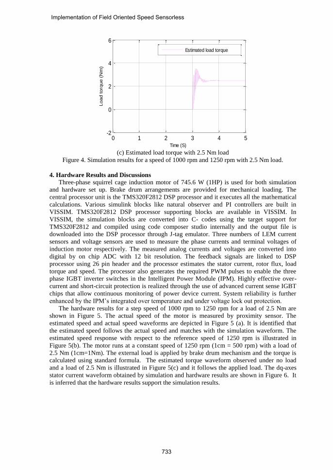
(c) Estimated load torque with 2.5 Nm load
Figure 4. Simulation results for a speed of 1000 rpm and 1250 rpm with 2.5 Nm load.
4. Hardware Results and Discussions
Three-phase squirrel cage induction motor of 745.6 W (1HP) is used for both simulation
and hardware set up. Brake drum arrangements are provided for mechanical loading. The
central processor unit is the TMS320F2812 DSP processor and it executes all the mathematical
calculations. Various simulink blocks like natural observer and PI controllers are built in
VISSIM. TMS320F2812 DSP processor supporting blocks are available in VISSIM. In
VISSIM, the simulation blocks are converted into C- codes using the target support for
TMS320F2812 and compiled using code composer studio internally and the output file is
downloaded into the DSP processor through J-tag emulator. Three numbers of LEM current
sensors and voltage sensors are used to measure the phase currents and terminal voltages of
induction motor respectively. The measured analog currents and voltages are converted into
digital by on chip ADC with 12 bit resolution. The feedback signals are linked to DSP
processor using 26 pin header and the processor estimates the stator current, rotor flux, load
torque and speed. The processor also generates the required PWM pulses to enable the three
phase IGBT inverter switches in the Intelligent Power Module (IPM). Highly effective over-
current and short-circuit protection is realized through the use of advanced current sense IGBT
chips that allow continuous monitoring of power device current. System reliability is further
enhanced by the IPM’s integrated over temperature and under voltage lock out protection.
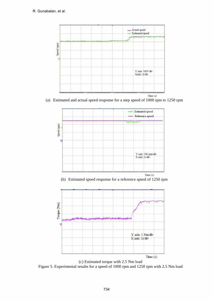
The hardware results for a step speed of 1000 rpm to 1250 rpm for a load of 2.5 Nm are
shown in Figure 5. The actual speed of the motor is measured by proximity sensor. The
estimated speed and actual speed waveforms are depicted in Figure 5 (a). It is identified that
the estimated speed follows the actual speed and matches with the simulation waveform. The
estimated speed response with respect to the reference speed of 1250 rpm is illustrated in
Figure 5(b). The motor runs at a constant speed of 1250 rpm (1cm = 500 rpm) with a load of
2.5 Nm (1cm=1Nm). The external load is applied by brake drum mechanism and the torque is
calculated using standard formula. The estimated torque waveform observed under no load
and a load of 2.5 Nm is illustrated in Figure 5(c) and it follows the applied load. The dq-axes
stator current waveform obtained by simulation and hardware results are shown in Figure 6. It
is inferred that the hardware results support the simulation results.
0 1 2 3 4 5-2
0
2
4
6
Load torq
ue (
Nm
)
Time (S)
Estimated load torque
Implementation of Field Oriented Speed Sensorless
733
(a) Estimated and actual speed response for a step speed of 1000 rpm to 1250 rpm
(b) Estimated speed response for a reference speed of 1250 rpm
(c) Estimated torque with 2.5 Nm load
Figure 5. Experimental results for a speed of 1000 rpm and 1250 rpm with 2.5 Nm load
R. Gunabalan, et al.
734
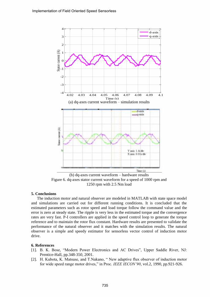
(a) dq-axes current waveform – simulation results
(b) dq-axes current waveform – hardware results
Figure 6. dq-axes stator current waveform for a speed of 1000 rpm and
1250 rpm with 2.5 Nm load
5. Conclusions
The induction motor and natural observer are modeled in MATLAB with state space model
and simulations are carried out for different running conditions. It is concluded that the
estimated parameters such as rotor speed and load torque follow the command value and the
error is zero at steady state. The ripple is very less in the estimated torque and the convergence
rates are very fast. P-I controllers are applied in the speed control loop to generate the torque
reference and to maintain the rotor flux constant. Hardware results are presented to validate the
performance of the natural observer and it matches with the simulation results. The natural
observer is a simple and speedy estimator for sensorless vector control of induction motor
drive.
6. References
[1]. B. K. Bose, “Modern Power Electronics and AC Drives”, Upper Saddle River, NJ:
Prentice-Hall, pp.348-350, 2001.
[2]. H. Kubota, K. Matsuse, and T.Nakano, “ New adaptive flux observer of induction motor
for wide speed range motor drives,” in Proc. IEEE IECON’90, vol.2, 1990, pp.921-926.
(d)
4.02 4.03 4.04 4.05 4.06 4.07 4.08 4.09 4.1-4
-3
-2
-1
0
1
2
3
4
Time (s)
Stat
or c
urre
nt (
A)
d-axis
q-axis
Implementation of Field Oriented Speed Sensorless
735
[3]. H. Kubota and K. Matsuse, “Speed sensorless field-oriented control of induction motor
with rotor resistance adaptation,” IEEE Trans. Industry Applications, vol. 30, pp. 1219–
1224, Sept. /Oct. 1994.
[4]. T. Yamada, K. Matsuse and K. Sasagawa, “Sensorless control of direct field oriented
induction motor operating at high efficiency using adaptive rotor flux observer”, in Proc.
IEEE, 1996, pp.1149-1154.
[5]. K. Matsuse, Y.Kouno, H.Kawai and J.Oikawa, “Characteristics of speed sensor-less
vector controlled dual induction motor drive connected in parallel fed by a single
Inverter”, IEEE Trans .Industry Applications., vol. 40, pp. 153-161, Jan./Feb. 2004.
[6]. K. Matsuse, Y. Kouno, H. Kawai and S. Yokomizo, “A Speed-sensor-less vector control
method of parallel-connected dual induction motor fed by a single inverter,” IEEE Trans.
Industry Applications, vol. 38, pp. 1566–1571, Nov./Dec. 2002.
[7]. Maurizio Cirrincione, Marcello Pucci, Giansalvo Cirrincione and Gérard-André
Capolino, “An Adaptive Speed Observer Based on a New Total Least-Squares Neuron for
Induction Machine Drives”, IEEE Trans. Industry Applications, vol. 42, no. 1, pp.89 -
104, January/February 2006.
[8]. Luigi Salvatore, Silvio Stasi, and Lea Tarchioni, “A new EKF-based algorithm for flux
estimation in induction machines”, IEEE Trans. Industrial Electronics, vol.40, no.5,
pp.496-504, October 1993.
[9]. Y.R. Kim, S.K. Sul and M.H. Park, “Speed sensorless vector control of induction motor
using Extended Kalman Filter”, IEEE Trans. Industry Applications., vol. 30, no. 5,
pp.1225-1233, September / October 1994.
[10]. H.W. Kim and S.K. Sul, “A New motor Speed Estimator Using Kalman Filter in Low-
Speed range”, IEEE Trans. Industry Applications, vol. 43, no. 4, pp.498-504, August
1996.
[11]. K. L. Shi, T. F. Chan, Y. K. Wong and S. L. Ho, “Speed estimation of an induction
motor drive using an optimized Extended Kalman Filter”, IEEE Trans. Industrial
Electronics, vol. 49, pp. 124-133, Feb. 2002.
[12]. M. Barut, S. Bogosyan and M. Gokasan, “Speed-sensorless estimation for induction
motors using Extended Kalman Filters”, IEEE Trans. Industrial Electronics, vol. 54,
no.1, pp. 272-280, Feb. 2007.
[13]. M. Barut, S. Bogosyan and M. Gokasan, “Experimental evaluation of Braided EKF for
sensorless control of induction motors”, IEEE Trans. Industrial Electronics, vol. 55, no.2,
pp. 620-632, Feb. 2008.
[14]. M. Tsuji , Y. Umesaki , R. Nakayama , and K. Izumi, “A Simplified MRAS based
sensorless vector control method of induction motor”, in proc. IEEE, 2002, pp.1090-1095.
[15]. Mohamed Rashed, Fraser Stronach and Peter Vas, “A Stable MRAS-based sensorless
vector control induction motor drive at low speeds”, in proc. IEEE, 2003, pp. 1181-1188.
[16]. R. Cardenas, R. Pena, G. Asher, J. Clare and J. Cartes, “MRAS observer for doubly fed
induction machines”, IEEE Trans. Energy Conversion, vol.19, no.2, pp. 467-468, June
2004.
[17]. M. Cirrincione, M. Pucci, G. Cirrincione and G. A. Capolino, “A new TLS-based MRAS
speed estimation with adaptive integration for high- performance induction machine
drives”, IEEE Trans. Industry Applications, vol. 40, no.4, pp.1116-1137, July/Aug. 2004.
[18]. M. Cirrincione and M. Pucci, “An MRAS-based sensorless high-performance induction
motor drive with a predictive adaptive model”, IEEE Trans. Industrial Electronics, vol.
52, no.2, pp. 532-551, April 2005.
[19]. S. R. Bowes, A. Sevinc and D. Holliday, “New natural observer applied to speed
sensorless DC servo and induction motors”, IEEE Trans. Industry Applications, vol. 51,
no.5, pp. 1025–1032, Oct. 2004.
[20]. J. Guzinski, M. Diguet, Z. Krzeminski, A. Lewicki and H. Abu-Rub, “Application of
speed and load torque observers in high- speed train drive for diagnostic purposes”, IEEE
Trans. Industry Applications, vol. 56, no. 1, pp.248-256, Jan. 2009.
R. Gunabalan, et al.
736
[21]. J. Guzinski and H. Abu-Rub, M. Diguet, Z. Krzeminski and A. Lewicki “Speed and load
torque observer application in high speed train electric drive”, IEEE Trans. Industry
Applications, vol. 57, no. 2, pp.565-574, Feb. 2010.
[22]. Adnan Derdiyok, “Speed-Sensorless Control of Induction Motor Using a Continuous
Control Approach of Sliding-Mode and Flux Observer”, IEEE Trans. Industry
Applications, vol. 52, no. 4, pp.1170-1176, August 2005.
[23]. C. Lascu and G.D. Andreescu, “Sliding mode observer and improved integrator with DC-
offset compensation for flux estimation in sensorless controlled induction motors”, IEEE
Trans. Industrial Electronics, vol. 53, no.3, pp.785-794, Feb.2006.
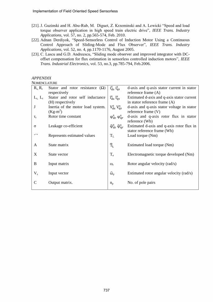
APPENDIX
NOMENCLATURE
Rs, Rr Stator and rotor resistance (Ω)
respectively idss iqs
s d-axis and q-axis stator current in stator
reference frame (A)
Ls, Lr Stator and rotor self inductance
(H) respectively idss iqs
s Estimated d-axis and q-axis stator current
in stator reference frame (A)
J Inertia of the motor load system.
(Kg-m2)
Vdss Vqs
s d-axis and q-axis stator voltage in stator
reference frame (V)
τr Rotor time constant φdrs φqr
s d-axis and q-axis rotor flux in stator
reference (Wb)
σ Leakage co-efficient φdrs φqr
s Estimated d-axis and q-axis rotor flux in
stator reference frame (Wb)
‘ˆ’ Represents estimated values TL Load torque (Nm)
A State matrix TL Estimated load torque (Nm)
X State vector Te Electromagnetic torque developed (Nm)
B Input matrix ωr Rotor angular velocity (rad/s)
Vs Input vector ωr Estimated rotor angular velocity (rad/s)
C Output matrix. np No. of pole pairs
Implementation of Field Oriented Speed Sensorless
737
R. Gunabalan obtained his B.E. degree in Electrical and Electronics
Engineering from Manonmanium Sundaranar University, Tirunelveli,
TamilNadu in 2000 and M.Tech. degree in Electrical Drives and Control
from Pondicherry University in 2006. He did his Ph.D from Anna
University, Chennai, TamilNadu in 2015. He is working as an Associate
Professor in the School of Electrical and Electronics Engineering, VIT
University-Chennai, TamilNadu, India. He has published / presented around
30 papers in National and International Journals / Conferences. His research
interests are in the areas of dc-dc power converters and estimation and control of induction
motor drives. He is a life member of ISTE and a member of IEEE.
V. Subbiah obtained his BE (Electrical) degree from Madras University,
India in 1965, ME (Control Systems) from Calcutta University in 1968 and
PhD (Power Electronics) from Madras University in 1981.
He has been associated with Technical Education for more than four
decades. He worked at PSG College of Technology, Coimbatore, India in
various capacities and retired in May 2000. Then, he joined the Faculty of
Engineering, Multimedia University, Malaysia in June 2000 on a contract
appointment for two years. After returning to India, he joined Sri Krishna
College of Engineering and Technology, Coimbatore in August 2002 as the Dean of Electrical
Sciences and continued in that capacity till 2013. Currently, he is working as a visiting
professor at PSG College of Technology, Coimbatore.
Dr Subbiah has taught undergraduate as well as postgraduate courses for more than 40 years.
He has published / presented around 80 papers in National and International Journals /
Conferences.
He is a Senior Member of IEEE (USA), a Fellow of the Institution of Engineers (India), and a
Life Member of Indian Society for Technical Education. His area of interest includes Power
Electronics, Electrical Drives and Control Systems.
R. Gunabalan, et al.
738


