
IOSR Journal of Electronics and Communication Engineering (IOSR-JECE)
e-ISSN: 2278-2834,p- ISSN: 2278-8735.Volume 9, Issue 4, Ver. III (Jul - Aug. 2014), PP 30-36 www.iosrjournals.org
www.iosrjournals.org 30 | Page
Implementation of Fir Filter Using a Novel modulo Adder for 2n-
2k-1 Residue Number System
1G.V. Padmaja,
2B. Sarala
1M.E (ES & VLSI Design) M.V.S.R Engineering College 2Associate Professor M.V.S.R Engineering College
Abstract: Modular adder is used in Residue Number System (RNS) addition. Moduli set with the form of 2n-2k-
1(1≤ k≤ n-2) can offer excellent balance among the RNS channels for multi-channel RNS processing. In this
paper, a Finite Impulse Response (FIR) filter using a novel algorithm and its Very Large Scale Integration
(VLSI) implementation structure are proposed for modulo 2n-2k-1 adder. In the Modular adder algorithm,
parallel prefix operation and carry correction techniques are adopted to eliminate the re-computation of
carries. Any existing parallel prefix structure can be used in the novel modulo adder. Thus, we can get flexible
tradeoff between area and delay. This paper presents FIR filter implementation with modulo 2n-2k-1 adder and
compared to the conventional FIR filter. This method improves speed, reduces power, delay and area.
Key words: RNS, modulo adder, LFSR, FIR filter
I. Introduction RNS is a non-weighted numerical representation system and has carry-free property in multiplication
and addition operations. Recent days, it has received intensive study in the VLSI circuits design for digital
signal processing (DSP) systems with high speed and low power consumption [2].
For integers A and B, whichareof n-bit width, addition is performed [1].
𝐶 = 𝐴 + 𝐵 𝑚 = 𝐴 + 𝐵𝐴 + 𝐵 + 𝑇 < 2𝑛
𝐴 + 𝐵 + 𝑇 2𝑛𝐴+ 𝐵 + 𝑇 ≥ 2𝑛
In the above equation, one of the outputsis selected by given condition. The effective modulo adders in
RNS are 2n-1, 2n, 2n+1. These2n-1 and 2n+1 adders are based on parallel prefix and carry correction respectively.
Some modulo 2n-2n-2-1 adder based on the technique of carry offset, which is only required to obtain the carry
information of A+B. In order to find the carries for addition each carry is modified to the utmost carry[4]. By
using carry computation,the block corrects the carries further in the proposed modulo adder. In this paper, the
modulo adder 2n-2k-1 is based on the carry correction and parallel prefix addition is proposed. This modulo
adder is divided into four units pre-processing unit, the prefix computation unit, the carry correction unit, and
the sum computation unit.
This paper is organized as follows: section II describes the RNS background and arithmetic operation. Section III describesthe novelmodulo2n-2k-1 adder and it’s self-testing. Section IV describesthe application of
modulo adder in FIR filter. In section V simulation results and comparisons are presented and in section VI
conclusion are listed.
II. Related Work Shang Ma, Jian-Hao Hu, and Chen-Hao Wang proposed “A Novel Modulo2n-2k-1 Adder for Residue
Number System”. In this system the addition operation is performed using the modulo 2n-2k-1. The sum
computation operation is done in the adder, which consists of four units, which eliminates re-computation of
carries. This system provides excellent performance and reduces the delay and area, thereby reducing the power.
This paper explains the implementation of FIR filter using the novel modulo 2n-2k-1 adder to show the
better performance compared to standard adders used in the filter. Also, the same modulo adder is used in Built
In Self Test (BIST) for self-testing using the Linear Feedback Shift Registers (LFSR).
III. RNS background and Arithmetic Operation. An RNS is defined by a set of relatively prime integers called the moduli. Each integer X can be
represented as a set of smaller integers called the residues[3]. This relation can be notationally written based on
the congruence:
𝑋𝑚𝑜𝑑𝑚𝑖 = 𝑟𝑖
The RNS is capable of uniquely representing all integers X that lie in its dynamic range. The dynamic
range is determined by the moduli-set {m1, m2,…,mn} and denoted as M where,

Implementation of Fir Filter Using a Novel modulo Adder for 2n-2k-1 Residue Number System
www.iosrjournals.org 31 | Page
𝑀 = 𝑚𝑖
𝑛
𝑖=1
Algebraic Operations
Addition and subtraction of different numbers in the RNS representation is done by individually adding
or subtracting the residues with respect to the corresponding moduli.
Consider the moduli-set S = {m1, m2… mn} and the numbers A and B are given in RNS representation:
𝑋 = {𝐴1,𝐴2…𝐴𝑛} 𝑎𝑛𝑑𝑌 = {𝐵1,𝐵2…𝐵𝑛} Then,
𝑍 = 𝐴 ∓ 𝐵 = {𝑧1 , 𝑧2 …𝑧𝑛 } Where𝑧𝑖 = (𝐴𝑖 ∓ 𝐵𝑖) 𝑚𝑜𝑑𝑚𝑖
This property may be applied to subtraction as well, where subtraction of B from A is considered as the
addition of𝐵 .
The modulo operation is distributive over addition or subtraction:
𝐴 ∓ 𝐵 𝑚 = 𝐴 𝑚 ∓ 𝐵 𝑚 𝑚
(1)
IV. Modulo 2n-2
k-1adder
The novel modulo 2n-2k-1 structure is shown in figure(1), which consists of fourmodules, pre-
processing unit,carry generation unit, carry correction unit, and sum computation unit. The modulo adder
divided into two binary adders with a carry correction and sum computation model, to get correction carries
Cirealfind from the process carries in preprocessing unit. At last to get the final modular addition with Ci
real and
partial sum information [1].
Fig.1: Modulo2n-2k-1 adder structure.
A. Pre-processing Unit
The preprocessing unit is used for generating carries and carry propagation bits.The computation can
be performed by A1 and A2 where A1 and A2 are used for lower k- bits and higher n-k bits addition
respectively [1].
For lower k-bits carry propagation is calculated as
𝑔0 ,𝑝0 = 𝑎0 + 𝑏0 ,𝑎0 ⊕𝑏0 𝑖 = 0(3)
𝑔𝑖 ,𝑝𝑖 = 𝑎𝑖𝑏𝑖 ,𝑎𝑖 ⊕𝑏𝑖 𝑖 = 1,2,… , 𝑘 − 1 (4)
For A2(n-k bits) first find by simple carry save adder process 𝑔𝑖 ′,𝑝𝑖 ′ = 𝑎𝑖𝑏𝑖 ,𝑎𝑖 ⊕𝑏𝑖 (5)
This 𝑔′and 𝑝′are inputs to next stage in A2 part addition. Then the output carry propagation for A2 is
𝑔𝑘 ,𝑝𝑘 = 𝑝𝑘′ ,𝑝𝑘
′ 𝑖 = 𝑘 (6)
𝑔𝑖 ,𝑝𝑖 = 𝑝𝑖′𝑔𝑖−1
′ ,𝑝𝑖′ ⊕𝑔𝑖−1
′ 𝑖 = 𝑘 + 1,… ,𝑛 − 1(7)
The carry out for first unit is CSCSA
𝐶𝑆𝐶𝑆𝐴 = 𝑎𝑛−1𝑏𝑛−1 = 𝑔′𝑛−1
(8)
Implementation of Fir Filter Using a Novel modulo Adder for 2n-2k-1 Residue Number System
www.iosrjournals.org 32 | Page
B. Carry Generation
In the carry generation unit, carry is generatedby carry look-ahead adder [1]
𝐶’𝑖+1 = 𝐺𝑖 + 𝑃𝑖𝐶𝑖(9)
C.Carry Correction Unit
The carry correction unit is used to get the real carries 𝐶𝑖+1𝑟𝑒𝑎𝑙 for each bit needed for final sum
generation [1] from equation 10.
𝐶𝑖+1𝑟𝑒𝑎𝑙 =
𝐶𝑖+1 𝐶𝑜𝑢𝑡 + 𝑃𝑖:0 𝑖 = 0,1, . . , 𝑘 − 1
𝐶𝑖+1 𝐶𝑜𝑢𝑡 + 𝑃𝑘−1:0 𝑝𝑘 ⊕𝐶𝑘 𝑖 = 𝑘
𝐶𝑖+1 𝐶𝑜𝑢𝑡 + 𝑃𝑖:𝑘+1 + 𝑃𝑘−1:0
𝑝𝑘 ⊕𝐶𝑘 𝑖 = 𝑘 + 1, . . ,𝑛 − 2
(10)
D. Sum Computation
The final sum is calculated by the real carries generated from the carry correction unit. The final sum is [1]
𝑆𝑖 = 𝐶𝑖𝑟𝑒𝑎𝑙 ⊕𝑝𝑖(11)
The sum bits are
𝑆𝑖 =
𝐶𝑜𝑢𝑡 ⊕𝑝0 𝑖 = 0
𝐶𝑘𝑟𝑒𝑎𝑙 ⊕𝐶𝑜𝑢𝑡 ⊕𝑝 𝑘 𝑖 = 𝑘
𝐶𝑖𝑟𝑒𝑎𝑙 ⊕𝑝𝑖𝑖 = 1,… ,𝑘 − 1, 𝑘 + 1,… , 𝑛 − 1
(12)
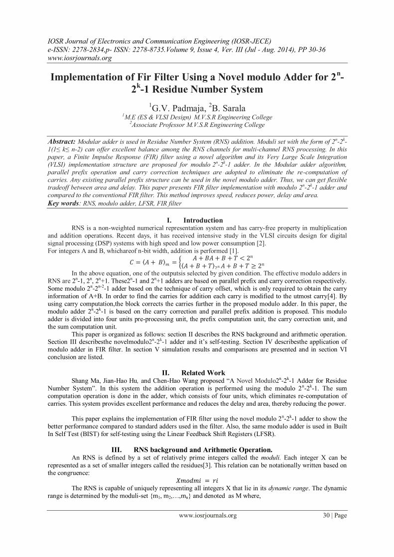
E.VLSI Implementation
Pre-Processing Unit: The pattern “ ” is the pre-processing unit and used to generate carry generation and carry propagation bits for
the following prefix computation. Since there are fixed “1” inputs at the 1st and the 4th places, the patterns “
” and “ ” are used for this special situations. The pattern “ ” does not cost any resource in unit-gate
model.
Carry Generation Unit:
The pattern “ ” is the prefix computation unit. In this example, the Sklansky prefix tree is used
and there are 11 prefix computation units. The delay of “ ” is determined by its’ carry generation path
which is one OR gate and one AND gate. However, the pattern “ ” in the final stage of prefix tree is not
needed to compute propagation bits. The is computed by pattern “ ”
Carry Correction Unit:
The pattern “ ” performsthe computation. Correspondingcorrection operators are used. There are
three different situations, that is i = 0,1,… , k − 1, i = k and i = k − 1,…n − 2. The Pi:0 , z1 and z2can be
computedPi:0 , z1 and z2 by independent modules. The pattern“ ” and “ ” is used to compute. CkT is
computed out before CiT(i = k + 1,… , n − 1) with two prefix computation stages. Hence, we can get and
Implementation of Fir Filter Using a Novel modulo Adder for 2n-2k-1 Residue Number System
www.iosrjournals.org 33 | Page
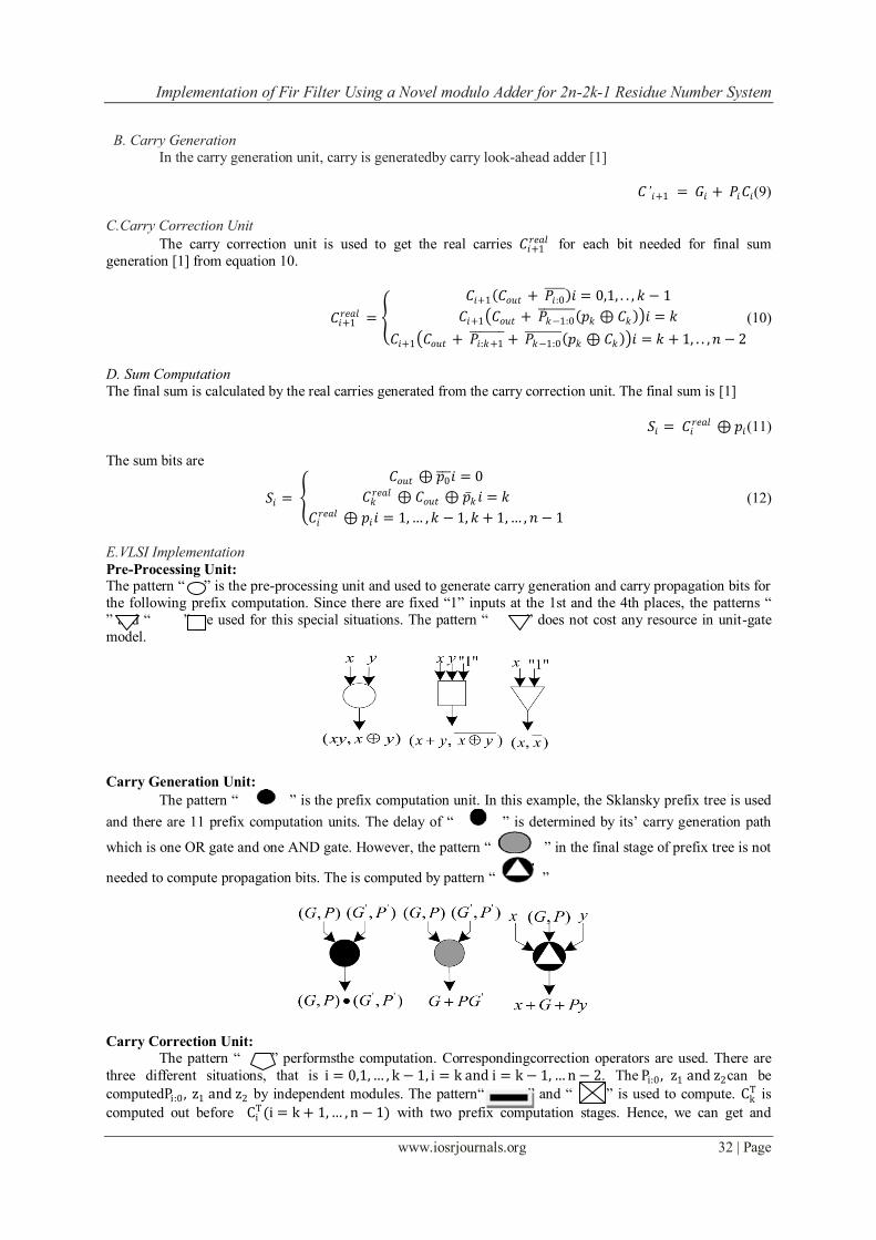
without extra delay. In the worst case, the group propagation bits required are needed to be computed one by
one frompi(i = 0,1,… , n − 2). However, the extra components for computing these group propagation bits can
be removed when the group propagation bits exist in prefix structure.
The Sum Computation:
The pattern “ ” is used for performing the sum computation. As a matter of fact, this operator is
the logic XOR operation. The pattern “ ” is a modified XOR operator, one of its inputs is inverted.
Because the computation can be performed with carry correction simultaneously, only one XOR operations are
required to perform the sum computation and no extra delay is introduced.
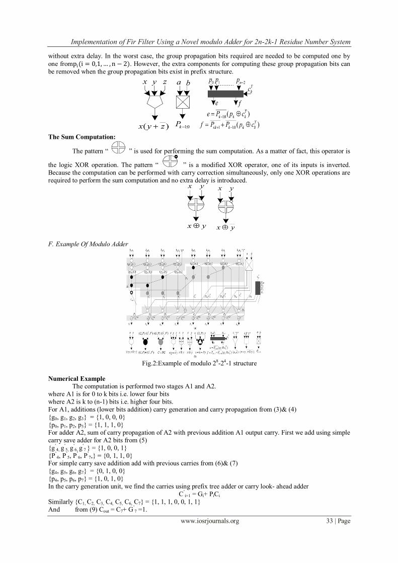
F. Example Of Modulo Adder
Fig.2:Example of modulo 28-24-1 structure
Numerical Example
The computation is performed two stages A1 and A2.
where A1 is for 0 to k bits i.e. lower four bits
where A2 is k to (n-1) bits i.e. higher four bits.
For A1, additions (lower bits addition) carry generation and carry propagation from (3)& (4)
{g0, g1, g2, g3} = {1, 0, 0, 0}
{p0, p1, p2, p3} = {1, 1, 1, 0}
For adder A2, sum of carry propagation of A2 with previous addition A1 output carry. First we add using simple
carry save adder for A2 bits from (5)
{g’4, g
’5, g
’6, g
’7 } = {1, 0, 0, 1}
{P’4, P
’5, P
’6, P
’7,} = {0, 1, 1, 0}
For simple carry save addition add with previous carries from (6)& (7)
{g4, g5, g6, g7} = {0, 1, 0, 0}
{p4, p5, p6, p7} = {1, 0, 1, 0}
In the carry generation unit, we find the carries using prefix tree adder or carry look- ahead adder
C’i+1 = Gi+ PiCi
Similarly {C1, C2, C3, C4, C5, C6, C7} = {1, 1, 1, 0, 0, 1, 1}
And from (9) Cout = C7+ G’7 =1.
Implementation of Fir Filter Using a Novel modulo Adder for 2n-2k-1 Residue Number System
www.iosrjournals.org 34 | Page
The carry correction unit is used for get the real carries 𝐶𝑖+1𝑟𝑒𝑎𝑙 for each bit needed for final sum generation from
(10)
{C1real, C2
real, C3real, C4
real, C5real, C6
real, C7real} = {1, 1, 1, 0, 0, 1, 1}
The sum bits are from (12)
Then {S0, S1, S2, S3, S4, S5, S6, S7} = {1, 0, 0, 1, 1, 0, 0, 1} = 153
Manually,
G. Self-Testing
A built-in self-test (BIST) is a mechanism that allows a machine to test itself. The purpose of BIST
is to reduce the complexity, and thereby decrease the cost and reduces the dependence upon external (pattern-
programmed) test equipment. A random number generator is a computational or physical device designed to
generate a sequence of number that lack any pattern i.e. appear random. Here, in this paper we are generating
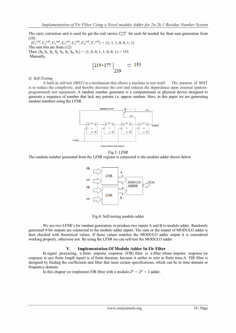
random numbers using the LFSR.
Fig.3: LFSR
The random number generated from the LFSR register is connected to the modulo adder shown below
Fig.4: Self-testing modulo adder
We use two LFSR’s for random generation, to produce two inputs A and B to modulo adder. Randomly
generated 8-bit outputs are connected to the modulo adder inputs. The sum or the output of MODULO adder is
then checked with theoretical values. If those values matches the MODULO adder output it is considered
working properly, otherwise not. By using the LFSR we can self-test the MODULO adder
V. Implementation Of Modulo Adder In Fir Filter In signal processing, a finite impulse response (FIR) filter is a filter whose impulse response (or
response to any finite length input) is of finite duration, because it settles to zero in finite time.A FIR filter is
designed by finding the coefficients and filter that meet certain specifications, which can be in time-domain or
frequency-domain.
In this chapter we implement FIR filter with a modulo 2𝑛 − 2𝑘 − 1 adder.

Implementation of Fir Filter Using a Novel modulo Adder for 2n-2k-1 Residue Number System
www.iosrjournals.org 35 | Page
Fig.5: FIR filter with modulo 2𝑛 − 2𝑘 − 1 adder
In this, the input signal is multiplied with the coefficients and single clock delay is added through the
adder. The adder which is used asthe modulo2𝑛 − 2𝑘 − 1 adder. The main advantage of using this adder in the filter is that, it reduces the computation time. It also reduces area, delay, power and complexity. It improves speed of FIR filter.
VI. Simulation Results The simulation is done in Xilinx’s 14.4 tool. The results of the modulo2𝑛 − 2𝑘 − 1 adder as shown in
figure. 6 and 7 andfigure 8 shows the result of self-testing of modulo adder using LFSR. The application of FIR
filter using modulo adder is shown in figure9.
Fig.6: Simulation results of modulo adder
Fig.7: Simulation results of modulo adder
Fig.8: Simulation results of self-testing modulo adder with LFSR
Implementation of Fir Filter Using a Novel modulo Adder for 2n-2k-1 Residue Number System
www.iosrjournals.org 36 | Page
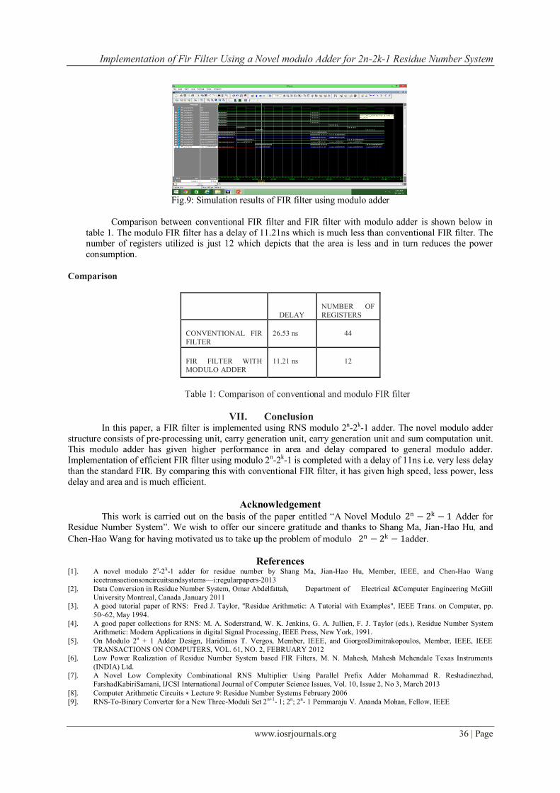
Fig.9: Simulation results of FIR filter using modulo adder
Comparison between conventional FIR filter and FIR filter with modulo adder is shown below in
table 1. The modulo FIR filter has a delay of 11.21ns which is much less than conventional FIR filter. The number of registers utilized is just 12 which depicts that the area is less and in turn reduces the power
consumption.
Comparison
DELAY
NUMBER OF
REGISTERS
CONVENTIONAL FIR
FILTER
26.53 ns
44
FIR FILTER WITH
MODULO ADDER
11.21 ns
12
Table 1: Comparison of conventional and modulo FIR filter
VII. Conclusion In this paper, a FIR filter is implemented using RNS modulo 2n-2k-1 adder. The novel modulo adder
structure consists of pre-processing unit, carry generation unit, carry generation unit and sum computation unit. This modulo adder has given higher performance in area and delay compared to general modulo adder.
Implementation of efficient FIR filter using modulo 2n-2k-1 is completed with a delay of 11ns i.e. very less delay
than the standard FIR. By comparing this with conventional FIR filter, it has given high speed, less power, less
delay and area and is much efficient.
Acknowledgement
This work is carried out on the basis of the paper entitled “A Novel Modulo 2n − 2k − 1 Adder for Residue Number System”. We wish to offer our sincere gratitude and thanks to Shang Ma, Jian-Hao Hu, and
Chen-Hao Wang for having motivated us to take up the problem of modulo 2n − 2k − 1adder.
References [1]. A novel modulo 2
n-2
k-1 adder for residue number by Shang Ma, Jian-Hao Hu, Member, IEEE, and Chen-Hao Wang
ieeetransactionsoncircuitsandsystems—i:regularpapers-2013
[2]. Data Conversion in Residue Number System, Omar Abdelfattah, Department of Electrical &Computer Engineering McGill
University Montreal, Canada ,January 2011
[3]. A good tutorial paper of RNS: Fred J. Taylor, "Residue Arithmetic: A Tutorial with Examples", IEEE Trans. on Computer, pp.
50~62, May 1994.
[4]. A good paper collections for RNS: M. A. Soderstrand, W. K. Jenkins, G. A. Jullien, F. J. Taylor (eds.), Residue Number System
Arithmetic: Modern Applications in digital Signal Processing, IEEE Press, New York, 1991.
[5]. On Modulo 2n + 1 Adder Design, Haridimos T. Vergos, Member, IEEE, and GiorgosDimitrakopoulos, Member, IEEE, IEEE
TRANSACTIONS ON COMPUTERS, VOL. 61, NO. 2, FEBRUARY 2012
[6]. Low Power Realization of Residue Number System based FIR Filters, M. N. Mahesh, Mahesh Mehendale Texas Instruments
(INDIA) Ltd.
[7]. A Novel Low Complexity Combinational RNS Multiplier Using Parallel Prefix Adder Mohammad R. Reshadinezhad,
FarshadKabiriSamani, IJCSI International Journal of Computer Science Issues, Vol. 10, Issue 2, No 3, March 2013
[8]. Computer Arithmetic Circuits ∗ Lecture 9: Residue Number Systems February 2006
[9]. RNS-To-Binary Converter for a New Three-Moduli Set 2n+1
- 1; 2n; 2
n- 1 Pemmaraju V. Ananda Mohan, Fellow, IEEE


![FPGA DESIGN - Chennai tiltles/2017-2018/fpga... · 2017-07-19 · (4 + 2log n)ΔG Parallel Prefix Modulo-(2n − 3) Adder via Double Representation of Residues in [0, 2] 2016 QCA](https://static.documents.pub/doc/80x56/5e8a2f89099e566aba182807/fpga-design-chennai-tiltles2017-2018fpga-2017-07-19-4-2log-ng-parallel.jpg)


