
Improvement of Top-up Operation
Development of the Bunch current monitor [1]
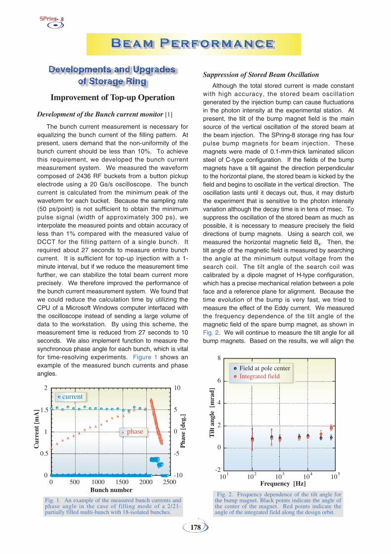
The bunch current measurement is necessary forequalizing the bunch current of the filling pattern. Atpresent, users demand that the non-uniformity of thebunch current should be less than 10%. To achievethis requirement, we developed the bunch currentmeasurement system. We measured the waveformcomposed of 2436 RF buckets from a button pickupelectrode using a 20 Gs/s oscilloscope. The bunchcurrent is calculated from the minimum peak of thewaveform for each bucket. Because the sampling rate(50 ps/point) is not sufficient to obtain the minimumpulse signal (width of approximately 300 ps), weinterpolate the measured points and obtain accuracy ofless than 1% compared with the measured value ofDCCT for the filling pattern of a single bunch. Itrequired about 27 seconds to measure entire bunchcurrent. It is sufficient for top-up injection with a 1-minute interval, but if we reduce the measurement timefurther, we can stabilize the total beam current moreprecisely. We therefore improved the performance ofthe bunch current measurement system. We found thatwe could reduce the calculation time by utilizing theCPU of a Microsoft Windows computer interfaced withthe oscilloscope instead of sending a large volume ofdata to the workstation. By using this scheme, themeasurement time is reduced from 27 seconds to 10seconds. We also implement function to measure thesynchronous phase angle for each bunch, which is vitalfor time-resolving experiments. Figure 1 shows anexample of the measured bunch currents and phaseangles.
Suppression of Stored Beam Oscillation
Although the total stored current is made constantwith high accuracy, the stored beam oscillationgenerated by the injection bump can cause fluctuationsin the photon intensity at the experimental station. Atpresent, the tilt of the bump magnet field is the mainsource of the vertical oscillation of the stored beam atthe beam injection. The SPring-8 storage ring has fourpulse bump magnets for beam injection. Thesemagnets were made of 0.1-mm-thick laminated siliconsteel of C-type configuration. If the fields of the bumpmagnets have a tilt against the direction perpendicularto the horizontal plane, the stored beam is kicked by thefield and begins to oscillate in the vertical direction. Theoscillation lasts until it decays out, thus, it may disturbthe experiment that is sensitive to the photon intensityvariation although the decay time is in tens of msec. Tosuppress the oscillation of the stored beam as much aspossible, it is necessary to measure precisely the fielddirections of bump magnets. Using a search coil, wemeasured the horizontal magnetic field Bx. Then, thetilt angle of the magnetic field is measured by searchingthe angle at the minimum output voltage from thesearch coil. The tilt angle of the search coil wascalibrated by a dipole magnet of H-type configuration,which has a precise mechanical relation between a poleface and a reference plane for alignment. Because thetime evolution of the bump is very fast, we tried tomeasure the effect of the Eddy current. We measuredthe frequency dependence of the tilt angle of themagnetic field of the spare bump magnet, as shown inFig. 2. We will continue to measure the tilt angle for allbump magnets. Based on the results, we will align the
178
Fig. 2. Frequency dependence of the tilt angle forthe bump magnet. Black points indicate the angle ofthe center of the magnet. Red points indicate theangle of the integrated field along the design orbit.
Fig. 1. An example of the measured bunch currents andphase angle in the case of filling mode of a 2/21-partially filled multi-bunch with 18-isolated bunches.

179
bump magnets. In addition, we will design the tiltcontrol system for the bump magnets, which is used ata beam-based alignment to suppress the verticaloscillation.
Installation of Counter-Sextupole Magnets in Long Straight Sections
In the summer shutdown of 2000, we had locallyremoved and rearranged quadrupole and sextupolemagnets to realize magnet-free long straight sections[2]. At that time, three unit cells were converted to thematching section, as shown in Fig. 3. The betatronphase advance in this section was set at 2πn, where nis an integer (n=2 in the horizontal direction and n=1 inthe vertical direction). Then, if no sextupole magnetsare excited in the matching section, this part becomes"transparent," i.e., the electrons at the exit will have thesame position and angle as they had at the entrance,and the periodicity of the ring can be kept high evenafter introducing long straight sections into the ring.This betatron phase matching is effective for obtaininglarge dynamic apertures and, hence, for realizing beaminjection with high efficiency.
Such a phase condition, however, holds only forelectrons with a design momentum. Because the beamis focused horizontally in the arc section by strongquadrupole magnets, the effect of chromatic aberrationover the matching section is non-negligible. If the localchromaticity is uncorrected, off-momentum electronsreceive a different focusing force from on-momentumones, and betatron phase-slip occurs. As a result, themomentum acceptance of the ring becomes narrowand the Touschek beam lifetime becomes short. Tocorrect the local chromaticity and enlarge themomentum acceptance, we have to excite sextupolemagnets in the matching section. This, however, causea harmful effect on the betatron phase matching and
the dynamic aperture becomes smaller. At present, asa compromise, we excite only one family of sextupole inthe matching section with a weak strength, labeled "SF"in Fig. 3, and both beam lifetime and injection efficiencyare at acceptable levels for top-up operation.
To obtain longer beam lifetime and higher injectionefficiency for stable top-up operation, we need toenlarge the dynamic aperture for on- and off-momentum electrons. For this purpose, we haverecently developed a new scheme of local chromaticitycorrection. In this scheme, we use additionalsextupoles which cancel nonlinear kicks due to SF inan approximate manner. These are "S1" and "SCT" inFig. 3, and these are separated from SF by about π inthe horizontal betatron phase. The magnet S1 hasalready been installed from the beginning, and SCT is anew one which we call counter-sextupole. Theinstallation of counter-sextupole magnets will becompleted in 2007.
After installing the counter-sextupole magnets, wecan make the matching section "transparent" both foron- and off-momentum electrons. This also means thatthe optics will become more flexible; i.e., it will becomeeasier to independently tune the local optics at eachlong straight section. This is another advantage ofinstalling counter-sextupole magnets. In Fig. 4, weshow the calculated dynamic apertures. Themomentum deviation is indicated by δ. We see that thedynamic aperture is enlarged by introducing thecounter-sextupole.
Fig. 3. Linear optics of the matching section andarrangement of the main magnets (blue: bending;green: quadrupole; orange: sextupole).
Fig. 4. Dynamic apertures at the injectionpoint before (dashed lines) and after (solidlines) installing the counter-sextupole magnets.The momentum deviation is indicated by δ.

180
Renewal of BPM Electronics
The signal processing electronic circuits of theSPring-8 storage ring beam position monitors (BPM)were replaced during the summer shutdown of 2006.All of the 24 sets of circuits covering the entire ringwere replaced at this time to improve the closed orbitdistortion (COD) measurement performance.
The electronics are configured to measure theamplitude of the single component of 508.58 MHz,which is the RF acceleration frequency, in the signalinduced on the electrodes by the electron beams (Fig.5). The input signals from 12 electrodes of 3 BPMsare multiplexed in the switch-filter module, andprocessed in one common path of the circuits. Oneset of the circuits is composed of four of these paths.After the multiplexing stage, signals go through band-pass filters (BPF) to select the RF accelerationfrequency component in the pickup signals. Theselected narrow-band RF signals are amplified anddown-converted to 250 kHz intermediate frequency(IF) signal, amplified with variable-gain IF amplifiers,and sampled by 16-bit 2MSPS (mega samples persecond) ADCs. Finally, the signal amplitudes arecalculated in digital signal processors (DSP) using thedigital data sampled by ADCs. In addition, the DSPhas the following three functions: calculating the beampositions, setting the gain of the IF amplifier andswitching the multiplexer, and communicating with thecontrol system of the accelerator complex.
During the usual operation for user experiments,the position data are averaged for 100 times in theDSPs to improve the position resolution. It takesabout 3 seconds to process all of the BPM around the
entire ring. Since the old circuits, which were useduntil the 2006 summer shutdown, require more than 20seconds to measure beam positions of the entire ring,the measurement speed improved by a factor of 7.
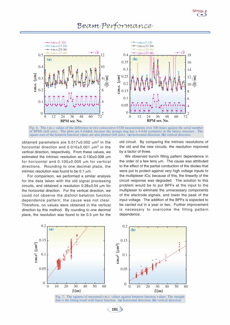
We continuously measured the COD every fourseconds in order to estimate the position resolution;the differences in the two consecutive measurementswere calculated to obtain the root mean square(r.m.s.) value of over a hundred measurements foreach BPM. The r.m.s. value of each BPM includesthe intrinsic resolution of the measurement systemand also the movement of the COD between the twoconsecutive measurements. Figure 6 shows ther.m.s. values against the BPM serial numbers. Acharacteristic pattern appears in the graph. It seemsthat this pattern relates to the betatron functionvalues. The square root of the betatron functionvalues are also plotted in the same graph. Thepattern observed in the r.m.s. values agrees well withthe square root of the betatron function values whenscaled and shifted properly.
We can postulate a model showing that themeasured r.m.s. values can be decomposed to theintrinsic resolution and the effect of beam motionwhose amplitude is proportional to the square root ofthe betatron function values at the BPM locations.According to the decomposition model, the measuredr.m.s. values are expressed as
σi2 = σ0
2 + σ 2CODi
= σ02 + ε0 × βi ,
where σi is the measured r.m.s. value of the i-th BPM,σ0 is the intrinsic resolution, σCODi is the r.m.s. of theeffect of the COD movement at the i-th BPM, βi is thebetatron function value at i-th BPM, and ε0 is the
proportionality constant. Theassumptions in the model are thatthe intrinsic resolution is commonto all of the BPM, the amplitudesof the COD motion areproportional to the square root ofthe betatron function values, andthere is no correlation betweenthe intrinsic resolution and theCOD motion terms.
We plotted the squares ofr.m.s. against the betatronfunction values as in Fig. 7, andcarried out regression analysiswith linear model as σ 2 = a + b •β,where σ 2 is the measured r.m.s.,β is the beta function value, a andb are the fitting parameters. Theparameter a interests us; the
Fig. 5. Block diagram of one set of the signal processing circuits.
181
obtained parameters are 0.017±0.002 µm2 in thehorizontal direction and 0.010±0.001 µm2 in thevertical direction, respectively. From these values, weestimated the intrinsic resolution as 0.130±0.008 µmfor horizontal and 0.100±0.005 µm for verticaldirections. Rounding to one decimal place, theintrinsic resolution was found to be 0.1 µm.
For comparison, we performed a similar analysisfor the data taken with the old signal processingcircuits, and obtained a resolution 0.28±0.04 µm forthe horizontal direction. For the vertical direction, wecould not observe the distinct betatron functiondependence pattern; the cause was not clear.Therefore, no values were obtained in the verticaldirection by this method. By rounding to one decimalplace, the resolution was found to be 0.3 µm for the
old circuit. By comparing the intrinsic resolutions ofthe old and the new circuits, the resolution improvedby a factor of three.
We observed bunch filling pattern dependence inthe order of a few tens µm. The cause was attributedto the effect of the partial conduction of the diodes thatwere put to protect against very high voltage inputs tothe multiplexer ICs; because of this, the linearity of thecircuit response was degraded. The solution to thisproblem would be to put BPFs at the input to themultiplexer to eliminate the unnecessary componentsof the electrode signals, and lower the peak of theinput voltage. The addition of the BPFs is expected tobe carried out in a year or two. Further improvementis necessary to overcome the fi l l ing patterndependence.
Fig. 7. The squares of measured r.m.s. values against betatron function values. The straightline is the fitting result with linear function. (a) horizontal direction, (b) vertical direction.
Fig. 6. The r.m.s. values of the difference in two consecutive COD measurements over 100 times against the serial numberof BPMs (left axis). The plots are 4-folded, because the storage ring has a 4-fold symmetry in the lattice structure. Thesquare root of the betatron function values are also plotted (left axis). (a) horizontal direction, (b) vertical direction.

182
Development of Accelerator Diagnosis Beamlines
The accelerator diagnosis beamline I (BL38B2) hasa bunch purity monitor to evaluate the purity of the mainbunches of several-bunch operation modes [3] and anX-ray beam imager for beam emittance diagnosis [4].The data acquisition system of the bunch purity monitorand the X-ray beam imager was developed for real-timebeam monitoring. The bunch purity monitor is nowcontinuously monitoring the electron beam of the userexperiments under top-up injection. The continuousoperation of the X-ray beam imager is suspendedbecause of the degradation of the input photocathode ofthe X-ray zooming tube.
A study on the production of γ-ray photons in theenergy range of 10 MeV has been performed at thediagnosis beamline I [5]. The MeV γ-rays are generatedby the backward Compton scattering of opticallypumped far-infrared (FIR) laser photons from 8 GeVelectrons in the storage ring. Figure 8 shows themeasured energy spectra under the conditions of “FIRlaser on” and “FIR laser off”. The MeV photons andsynchrotron radiation less than 2 MeV were electricallydiscriminated by the detection circuits. Figure 8 alsoshows the net MeV γ-ray spectrum deduced bysubtracting the “FIR laser off” spectrum from the “FIRlaser on” spectrum. The estimated MeV photonproduction rate is 2×10³ photons/sec per FIR laseroutput power of 1 W.
The construction of the accelerator diagnosisbeamline II (BL05SS) is in progress. The front end andthe radiation shielding hutches have already beencompleted, and now, the so-called edge radiation fromthe bending magnets upstream and downstream of the
ID straight section of the beamline can be delivered tothe optics hutch I. To study the coherent synchrotronradiation in the wavelength region comparable to thebunch length, the intensity of the microwave componentof the edge radiation was measured as functions of thebunch length and the bunch current. A significantcorrelation between the microwave intensity and thebunch length was observed. To start the commissioningof the ID, which was installed in the summer of 2005, thesteering magnets of the ID were tuned for variousmagnet gaps. The development of the vacuumcomponents of the optics hutches I and II is in progress.The components of the optics hutch I, such as themovable mirror to pick off-the-edge radiation, the masks,the graphite filters, the metal filters, and the absorber,have been completed. The screen monitor and thedouble crystal monochromator, which is to be installed inthe optics hutch II, are under development. The x- andy-slits to shape the input X-ray beam of themonochromator, which are to be added to the front end,are also under development.
To produce highly intense MeV γ-ray photons, anadvanced plan of laser Compton scattering is inprogress at the diagnosis beamline II, which has astraight section suitable for interaction between FIRlaser photons and 8 GeV electrons. The expectedproduction rate of MeV photons is more than 105
photons/sec. The construction of the laser clean roomand the installation of the wave guide system for thetransport of the FIR laser have been completed.
Development of New Gate Valve with a Comb-type RF Shield
One of the limitations of the bunch current is theincrease in temperature of the finger-type RF shield of gatevalves. The finger-type RF shield, which is made fromBeCu, is attached for the smooth streaming of the wallcurrent induced by the electron beam. The contact forceof BeCu decrease because of the creep phenomena, if itstemperature increases to 150°C. The reduction in contactforce of BeCu induces more temperature increase, andfinally, the finger-type RF shield will break, and the gatevalve will not work. For example, the temperature of thefinger-type RF shield increases to more than 80°C with the203 bunches operation.
To realize the high-bunch current operation, it isnecessary to develop a gate valve with a new type of RFshield. KEK already developed the gate valve with a comb-type RF shield, and it is used in the KEK B-Factory [6]. Wetried to apply the comb-type RF shield to a new type of gatevalve in collaboration of KEK (Fig. 9). A prototype of thegate valve with a comb-type RF shield will be manufacturedby March 2007, and several tests will be scheduled.
Fig. 8. Measured energy spectra of MeV γ-raysgenerated by backward Compton scattering.

183
Development of Femtosecond Pulse X-ray Generation
The SPring-8 storage ring has a very small verticalbunch size. By using this feature, it is possible togenerate a femtosecond pulse X-ray (FSX) by thebunch slicing method [7,8]. The achievableperformance of the X-ray has been estimated for theoperating conditions of the storage ring by installingfour superconducting RF deflectors and a minipoleundulator. The calculated pulse width, flux density andX-ray energy are 600 fsec in two standard deviations,8.483×1015 photons/(sec • mrad2 • 0.1%BW • 100 mA),and 10.7 keV, respectively, for 4 GeV operation.
On the other hand, problems are discussed andtheir countermeasures are developed to realize theFSX generation. The required phase stability amongthe RF deflectors was determined to be as small as14.1 mdeg, and the mechanical vibration of cavitieswas considered as the main phase instability source.The phase stability of a superconducting cavity underoperation at KEK was studied to confirm the analyticalvibration model and to determine points of issue suchas vibration sources. A high-speed and high-powerphase shifter has been developed as a phase controldevice. Its phase control speed of 1 kHz at the 3 dBdown point with a ±1-degree span has been obtainedin a 300-kW power test. This year, the basic principleof FSX and a conceptual design are presented anddetails of the development will be reported next year.
The principle of FSX generation is shown in Fig. 10.The electrons in a bunch circulating in the storage ringhave a three-dimensional Gaussian distribution. Thebunch size in two standard deviations is 560 µm in thehorizontal, 13 µm in the vertical, and 12.5 mm (42psec) in the longitudinal or the traveling direction. Ifthis bunch is tilted, as shown in Fig. 10, the X-rayemitted from each part of the bunch is vertically
separated; the X-ray from the head of the bunchtravels in the upper space, and that from the tail in thelower space. If we place a slit along the X-ray path, asFig. 10, we can obtain a short pulse of X-ray emittedonly at around the center of the bunch, and the otherparts from the head and tail are blocked out. Thismethod enables a storage ring to generate FSX whosepulse width is much shorter than its bunch length. InFig. 10, the electrons do not collide with the slit if theslit is placed away from the electron orbit.
We have four 27-m magnet-free sections, calledlong straight sections, in the storage ring. Figure 11shows an example of FSX generator installed in one ofthe long straight sections. In this figure, we configuredfour RF deflectors and an insertion device. The bunchenters into the FSX generator from “A” in Fig. 11; itshead and tail are kicked to the opposite side by the firstdeflector “Def1.” The bunch then rotates in the driftspace “B”, and its rotation is stopped by the seconddeflector “Def2.” In the insertion device, the bunchemits X-ray in a stationary tilted position, and its tiltingis returned back to the initial position inversely by“Def3” and “Def4,” which are placed in a symmetricposition as “Def2” and “Def1.” The bunch has neitherrotation nor tilting at exit “A' ” of the FSX generator.Although a four-deflector design is shown here foreasy understanding, another low-cost two-deflectordesign would be possible if “Def2” and “Def3” arereplaced with two quadrupole magnets.
Fig. 10. Principle of FSX generation. A circulatingelectron bunch is kicked and tilted by RF deflectors.A portion of the emitted X-ray can pass through theslit. The bunch size and tilting are values for 8 GeV.
Fig. 9. Comb-type RF shield for SPring-8 gate valve.
Fig. 11. Conceptual design of FSX generator.Four RF deflectors and an insertion device areinstalled in the 27-m-long straight section.


