

Control Valves
In line & Angle Valves

Table of ContentsPage
SchuF Control Valves Introduction 3
Control Valve Types 4
In line Control Valves (Globe & Ball Type) 4
Angle Control Valves 6
Control Globe Valve Bonnet Selection 7
Control Valve Actuator Options 7
SchuF Control Curve Characterisation 8
Special Trim Types 9
Cage 9
Needle Spline 9
Stacker - Kinetic Energy Control Solution 10
Multi Stage Axial Flow 10
Standard Materials 11
Globe Control Valve Standard Dimensions 12
Angle Control Valve Standard Dimensions 13
Control Globe Standards 14
Product Portfolio Overview 15
©ey
eid
ea I
big
sto
ck.c
om
©la
gard
ieI b
igst
ock
.co
m©
laga
rdie
I big
sto
ck.c
om
©N
ost
al6i
e I b
igst
ock
.co
m©
Leo
nid
Ere
mey
chu
kI b
igst
ock
.co
m
2

SchuF Control Valves Introduction
Why choose SchuF?
The SchuF Group is an industry-renowned valve supplier with over 100 years´experience designing and manufacturing application-specific valve solutions.
SchuF has developed over 20,000 control valve variations in its hundred-year history. Each has its own specific characteristics tailored to the process control elements that are most important for it – pressure, level, flow or temperature.
SchuF has the capability to ship our unique and highly-praisedvalve solutions worldwide from production facilitieslocated in Germany, India, Ireland, Italy, the United Kingdom and the United States.
SchuF has an extensive product selection with a vastand diverse range of applications, from oil productionto concrete manufacture. SchuF´s skilled team ofengineers and product specialists design each valve‚from the ground up to meet specific applicationrequirements and provide optimal service life and performance.
Control valves work to keep a process variable such as flow or pressure within a predefined operating range. They are often the last piece of equipment in a process loop that can compensate a load disturbance and are therefore considered critical valves.
Where does SchuF use its expertise?
■ Discharge and feed flow-control valvein PET, PVC, PP & PE reactors
■ Level, pressure & steam injection controlvalves in PTA processes
■ Level control of flashing fluid in coalliquefaction or heavy oil upgrading
■ Feed and level control for gasification according to the Siemens, Lurgi, GE and Shell process licenses
■ Flow control of powder in fine chemical & pharmaceutical processes
■ Resurge and flare control for gas
■ Steam, feedwater and condensate control in power generation and Cogen/CHP facilities
■ High-precision multi-port flow control of highly viscous, non linear, non-Newtonian polymer fluids
■ Discharge flow control valves for urea reactorswhere urea-grade stainless steel is mandatory
■ Fully-jacketed short-body wafer control valves, for Nylon and PC production
■ Mineral processing applications such as high-pressure acid leaching (HPAL)
■ Sour water and Amine letdown in severalrefinery processes
■ Bio - Fuels (Renmatix)
■ Hydrocarbon fluid separation and injection in Oil and Gas industries
3
PVLV
FV
Control Valve Types
In line Control Valves
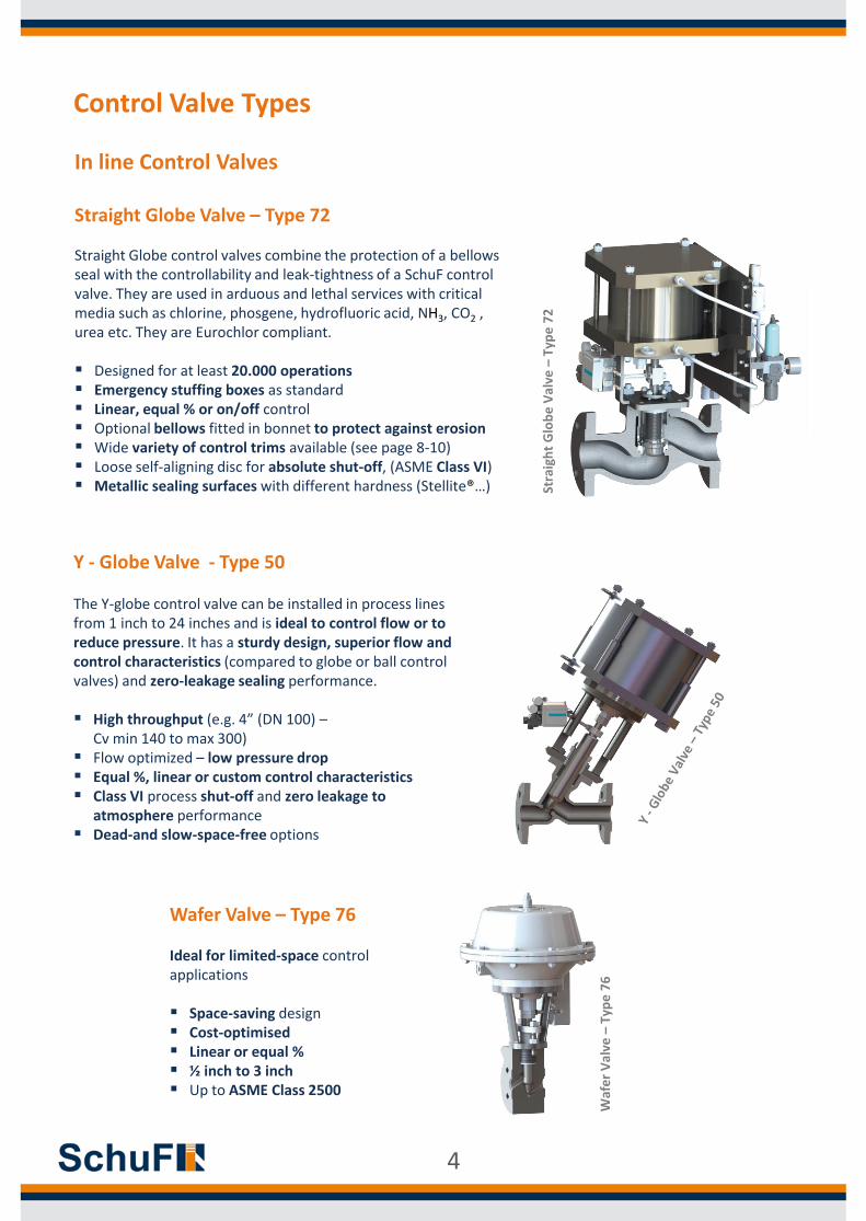
Straight Globe Valve – Type 72
Straight Globe control valves combine the protection of a bellows seal with the controllability and leak-tightness of a SchuF control valve. They are used in arduous and lethal services with critical media such as chlorine, phosgene, hydrofluoric acid, NH3, CO2 , urea etc. They are Eurochlor compliant.
Designed for at least 20.000 operations Emergency stuffing boxes as standard Linear, equal % or on/off control Optional bellows fitted in bonnet to protect against erosion Wide variety of control trims available (see page 8-10) Loose self-aligning disc for absolute shut-off, (ASME Class VI) Metallic sealing surfaces with different hardness (Stellite®…)
Y - Globe Valve - Type 50
The Y-globe control valve can be installed in process lines from 1 inch to 24 inches and is ideal to control flow or to reduce pressure. It has a sturdy design, superior flow and control characteristics (compared to globe or ball control valves) and zero-leakage sealing performance.
High throughput (e.g. 4” (DN 100) –Cv min 140 to max 300)
Flow optimized – low pressure drop Equal %, linear or custom control characteristics Class VI process shut-off and zero leakage to
atmosphere performance Dead-and slow-space-free options
Wafer Valve – Type 76
Ideal for limited-space control applications
Space-saving design Cost-optimised Linear or equal % ½ inch to 3 inch Up to ASME Class 2500
Stra
igh
t G
lob
e V
alve
–Ty
pe
72
Waf
er
Val
ve –
Typ
e 7
6
4

V-notch Ball Valve
By choosing the SchuF line of characterized V-Control ball valves, a full range of controlapplications is available with superior flow control. These quarter-turn-control ball valves are more compact, lighter weight and much less expensive than comparably sized globe valves and segmented control valves currently available in the market.
Superior rangeabilty and repeatability High flow capacity Ability to function with fluids containing
solids and fibers Ease of maintenance Exceptional interface with PLCs and computer
command signals SchuF´s high-quality pneumatic and electric
control actuators Accurate positioning
Control Valve Types
In line Control Valves
Segmented Ball Valve
The SchuF Segmented Ball Valve offers an accurate control with a clogging free design.High capacity and superior sealing propertiesmake this valve type a perfect In-Line valvefor control purposes, even with high solid content mediums.
Superior rangeabilty and repeatability High flow capacity Ability to function with fluids containing
solids and fibers Flow optimized – low pressure drop Erosive medium control Ease of maintenance and seal replacement Accurate positioning
Segm
en
ted
Bal
l Val
ve
V-n
otc
h B
all V
alve
5

Control Valve Types
Angle Control Valves – Model 74
The SchuF Model 74 Angle Control Valves are designed for critical or severe applications involving level control and pressure let-down in High Pressure Acid Leach (HPAL), Hydrocracking, Coal Liquefaction, PTA and other demanding processes.
The SchuF Angle Control Valve is often custom-made to suit process requirements in order to optimise field performance. Valve bodies are designed to help extend service life, by preventing impingement of particles on internal surfaces. Stagnant areas are minimized to prevent build-up of slurry or scale.
X-Flash – Type 74BS
These valves open into the downstream vessel to eliminate choking and cavitation. The “accelerating body” design prevents in-body flashing.
High CV values (1 to 3000) Low wear and tear Disc opening eliminates plugging by sediments Best suited for vessel installation
Tough Flash – Type 74CS
If piping considerations prohibit a disc-opening valve, the 74CS accomodates flashing in the valve while opening the disc into the body. The effects of cavitation are minimised by the use of suitable trims.
Hard material trim Flashing occurs in the protected seat/ choke tube area Up to 180 bar let-down is possible in a single stage Customised and replaceable choke tube Suitable for pipeline or vessel installation
Tou
gh F
lash
–Ty
pe
74
CS
X-F
lash
–Ty
pe
74
BS
6

Control Globe Valve Bonnet Selection
Standard Bonnet Cryogenic BonnetBellows Bonnet
Usually constructed of the same
material as the body.
Operating ΔT: -30°C to 400°C
Easily replaceable bellows assembly
Commonly used for lethal and hazardous service
Positive and Hermetic seal
Packing protected from excesive cold
Length of the bonnet meticulously calibrated
Operating ΔT: -163°C to 400°C
Long life-cycle (up to 10,000 cycles)
Operating ΔT: -30°C to 400°C
7
Control Valve Actuators
Pneumatic Hydraulic Electric Manual

SchuF Control Curve Characterisation
Curve Types
● Linear ● Equal Percentage● Quick Opening ● SchuF x3
● Linear
Linear flow characteristics are those where, for example, a 1%change of the total valve stroke will result in a flow rate change of 1% of the total flow. This ensures that, for a constant pressuredrop, the valve gain is more or less constant at all flows. Linear characteristics are suitable for most straightforward applications.
● Equal Percentage
Equal Percentage flow characteristics are commonly used wherepressure differential across the valve goes down as the flow rateIncreases, and are ideal for more complex process control. Equalpercentage valves open progressively more area as the valve is stroked open, so, for example, every 10% increase in stroke would result in a fixed percentage increase in the flow rate prior to adjustment- all across the stroke range.
● Quick Opening
Quick-Opening flow characteristics, as impliedby the title, allow maximum changes in flow ratefollowing small initial changes in valve stroke. Asthe valve travel approaches the fully open posit-ion, valve flow-rate changes approach zero. Thischaracteristic is commonly used for on-off service.
● SchuF x³ Bell Curve
SchuF’s patented x³ bell curve is available as analternative to the above characteristics. The hybridqualities of the x³ bell curve offer considerablyimproved controllability of the process.
8
in mm1 25
1,5 40
2 50
3 80
4 100
6 150
8 200
10 250
12 300
14 350
16 400
18 450
20 500
Valve SizeAvailable trim Cv for Standard Trims
15
45
80
160
300
4500
7000
600
1000
1400
2000
2500
3500

Special Trim Types
Cage
Ideal for energy dispersion and noise control
Multi-hole cage design – to achieve accurate flow characteristics and noise attenuation
Class VI (API 598) shut-off is achieved, eliminating unacceptable leakage
Linear or Equal % control characteristics
Available with fast-opening actuators, and smart positioners
Needle Spline
Ideal for micro flow applications from CV values up to 5.
The needle spline provides optimum rangeabilityand accurate flow control.
Excellent performance with high solid contentmedia for severe applications
Provides optimum guidance of the control head to prevent fracture when using hard metals
Bigger CV values are also available on request
9
in mm1 25
1,5 40
2 50
3 80
4 100
6 150
8 200
10 250
12 300
14 350
16 400
18 450
20 500
1500
2000
3000
150
300
400
600
900
1200
Valve SizeAvailable trim Cv for Cage Trims
10
20
45
90
in mm1 25
1,5 40
2 50
3 80
Valve SizeAvailable trim Cv for Needle Spline Trims
Microflow from 0,01 up to 5

Multi Stage Axial Flow
Ideal to let down high pressure over several stages and avoid cavitation:
2, 3 or up to 6 staged pressure - reduction disc design
Up to ASME Class 2500 as standard
True Equal % characteristics
High CV values (1 to 3000)
Large outlet chamber to reduce velocities
Disc opening direction eliminates plugging by catalyst fines or other sediments
10
in mm1 25
1,5 40
2 50
3 80
4 100
6 150
8 200
10 250
12 300
14 350
16 400
18 450
20 500
500
700
1000
50
100
150
200
250
350
Valve SizeAvailable trim Cv for Stacker Trims
10
20
in mm1 25
1,5 40
2 50
3 80
4 100
6 150
8 200
10 250
12 300
14 350
16 400
18 450
20 500 3000
35
70
200
300
400
600
900
1200
1500
2000
Valve SizeAvailable trim Cv for Multi Stage Trims
Special Trim Types
Stacker – Kinetic Energy Control Solution
By controlling the process through a series of torturous paths of expansions, contractions, fluid impingement and splitting channels,the exit velocity is reduced to a less aggressive level. Specially designed packing scraper and flow passage geometry prevents solids building up and reduces the need for servicing and production downtime:
More than 30 stages available Greatly reducing erosion, flashing damage, clogging and noise Eliminating cavitation, vibration and hydrate/condensate
formation Up to ASME Class 4500 (PN640) All body shapes available Class V and MSSP-61 shut-off For valve dimensions please consult factory

Standard Materials
Globe and Angle Control Body & Bonnet Materials
PRESSURE
RATING
Standard ASME Class 150 to ASME 2500
Other pressure applications are possible
TEMPERATURE
RATING
Standard -29°C to 260° C
Other temperature applications are possible
SHUT-OFF CLASSANSI/FCI 70-2 Class V / Class VI Available
API 598 / EN 1022-1
TRIM MATERIAL STANDARD STAINLESS TITANIUM ALLOYS SPECIALS
RECOMMENDED
SERVICE- Corrosive Highly Corrosive Highly Corrosive Abrasive
BODY
Carbon Steel
• DIN 1.0619
• A216 (WCB)
Duplex
• DIN 1.4462 / A 479 (S31803)
Stainless Steel
• DIN 1.4401 / A 182 (316)
• DIN 1.4404 / A 182 (316L)
• DIN 1.4552 / A 351 (CF8C)
TitaniumGrade 2
• Hastelloy(R)
• Incolloy®
• Inconel®
• Monel®
Cladded with Alloy Steel
TRIM
Carbon Steel
• DIN 1.0619
• A216 (WCB)
Stainless Steel
• DIN 1.4401 / A 182 (316)
• DIN 1.4404 / A 182 (316L)
• DIN 1.4541 / A 182 (321)
• DIN 1.4550 / A 182 (347)
Duplex
• DIN 1.4462 / A 479 (S31803)
Stainless Steel
• DIN 1.4401 / A 182(316)
• DIN 1.4404 / A 182 (316L)
• DIN 1.4541 / A 182 (321)
• DIN 1.4550 / A 182 (347)
• Nitronic
Titanium Grade 2 or 5
Titanium Grade 2 or 5
Hastelloy®
Incolloy®
Monel®
Cladded with Alloy Steel
Ceramic
Tungsten Carbide
Proprietary coatings
11

Globe Control Valve Standard Dimensions
¹ Additional sizes, connections, and configurations are available upon request; dimensions are subject to change. ² Threaded, BWE, RF, RTJ, API, BX, and PE connections are available for all sizes and configurations.³ ASME RF flanged dimensions are shown. Threaded, BWE, RTJ and ISO flanged dimensions are available upon request. A
B
H
ASME/ANSI RF Flanged Globe Control Valve Dimensions¹ ²
Body Size Inch (Din)
A (mm) ³
B(mm)
H (mm)
Integral Flange
Std.Bonnet
Ext. BonnetClass 150
PN10/16Class 300PN25/40
Class 600PN100
Class 900PN160
Class 1500PN250
Class 2500PN400
½“ (15) 108 152 165 216 - 264 38 97 212
¾“ (20) 117 178 190 229 229 273 38 97 212
1“ (25) 127 203 216 254 254 308 44 97 212
1½“ (40) 165 229 241 305 305 384 59 132 246
2“ (50) 203 267 292 368 368 451 59 138 252
3“ (80) 241 318 356 381 470 578 86 172 312
4“ (100) 292 356 432 457 546 673 133 214 354
6“ (150) 406 444 559 610 705 914 146 311 451
8“ (200) 495 559 660 737 832 1022 190 365 505
10“ (250) 622 622 787 838 991 1270 227 359 524
12“ (300) 698 711 838 965 1130 1422 318 413 578
14“ (350) 787 838 889 1029 1257 - 330 622 908
16“ (400) 914 864 991 1130 1384 - 400 721 1013
18“ (450) 978 991 1092 1219 1537 - 407 714 1020
20“ (500) 991 1143 1194 1321 1664 - 489 902 1082
24“ (600) 1143 1295 1397 1549 1943 - 508 864 1180
12

ASME/ANSI RF Flanged Angle Control Valve Dimensions¹ ²
Body Size (Din)
A/B (mm) ³
H (mm)Integral Flange
Class 150PN10/16
Class 300PN25/40
Class 600PN100
Class 900PN160
Class 1500PN250
Class 2500PN400
½“ (15) 51 76 83 - 108 132 229
¾“ (20) 57 89 95 114 114 137 234
1“ (25) 70 102 108 127 127 154 251
1½“ (40) 83 114 121 152 152 192 324
2“ (50) 102 133 146 184 184 226 364
3“ (80) 121 159 178 190 235 289 461
4“ (100) 146 178 216 178 273 337 551
6“ (150) 203 222 279 305 353 457 768
8“ (200) 248 279 330 368 416 511 876
10“ (250) 311 311 394 419 495 635 994
12“ (300) 349 356 419 483 565 711 1124
14“ (350) 394 - - 514 629 - -
16“ (400) 457 - - 660 - - -
18“ (450) - - - 737 - - -
20“ (500) - - - 826 - - -
24“ (600) - - - 991 - - -
¹ Additional sizes, connections, and configurations are available upon request; dimensions are subject to change. ² Threaded, BWE, RF, RTJ, API, BX, and PE connections are available for all sizes and configurations.³ ASME RF flanged dimensions are shown. Threaded, BWE, RTJ and ISO flanged dimensions are available upon request.
Angle Control Valve Standard Dimensions
13

Control Globe Standards Design Standards
ASME B16.10
ASME B16.34
ASME Boiler Pressure Vessel Code Sec. VIII
Pressure Equipment Directive (PED)
Testing Standards
API 6A PR2
API 17D
EN 10204
ASME B16.34
ISO 15848-1
ASME FCI 70-2
Sour Service StandardsNace MR-01-75
Nace MR0103
ISO 15156
Quality Standards
Pressure Equipment Directive (PED)
API Q1
API PSL 1,2,3 & 3G
ISO 10423-API 6A
EN ISO 9001
Add. StandardsISO 4406
EN ISO 9001
ATEX 96/9/EC
TR-CU
NORSOK
Additional Testing
StandardsANSI/ ISA S75.02
ANSI/ ISA S75.07
ANSI B16.104
Class IV & V
Flange Standards
ASME B16.5
ASME B16.47
EN 1092-1
ISO 10423-API 6A
API 17D
ASME B16.5
14

Product Portfolio Overview
The SchuF Group has delivered over one millionvalves during its 100 year history, to a wide varietyof industries in over 50 countries worldwide.Headquartered near Frankfurt, Germany, thecompany has additional design and manufacturingcentres in India, Ireland, Italy, UK, and the USA.
The SchuF Group has sales and agent officesservicing virtually every country in the world.We manufacture valve products that control,isolate, divert, and sample liquids, gases,powders, and slurries. Our extensive productrange of engineered, customized valves includes:
Aluminium Pechiney Auriga Polymers BASF CEPSA Chang Chun Petrochemical China Textile CTCI Formosa Chemicals & Fibre Far Eastern New Century Hengli Petrochemical Hebi Huashi United Energy Ignite Energy Resources
Jiangsu Hailun Petrochemical KBR Technology Lenzing Lurgi Nanjing Chemical OPTC Reliance Industries Renmatix SABIC Innovative Plastics Samsung Petrochemical Technip Uhde Inventa Fischer
Control Valve Client List:
Drain & Sampling Valves
Piston BottomOutlet Valves
Control Valves
Angle Control Valves
In-Line Control Valves
Multistage Control Valves
Cage Control Valves
AutomaticRecirculation Valve
(ARV)
Choke Valves
BlowdownValves
Isolation Valves
Standard & IsoPlugLift Plug Valves
TruEPlug Soft Sealing
Lift Plug Valves
Y- / P- Globe & Straightway Valves
High PressureAngle Valves
Special Ball Valves
Special Gate Valves
SwitchingValves
Y, R, & T type Diverter Valves
MultiwayDiverter Valves
SwitchPlug™ Multiway
Lift Plug Valves
ManiFlow Selector Valves™ (MSV)
Custom DiverterValves
Safety RelatedValves
Line Blind Systems
Goggle Valves
ChangeoverValves
In-Tank Emergency Shut-Off
Valves (TESO)
IsoTank® External Tank Emergency Shut-Off Valves
Non-Slam Check Valves
Spray Rinse & Injection Valves
Spray RinseValves
Steam InjectionValves
Disc BottomOutlet Valves
Sampling Systems
Bottom Outlet Ball Valves
Screw-in, Line & Wafer Sampling
Valves
15

PB
_EU
_Co
ntr
olV
alve
s-In
line&
An
gleV
alve
s_R
6_2
01
7-0
6


