
52nd North Carolina Industrial Ventilation Conference
Module DE-3-3 1
Industrial Fans 202Industrial Fans 202
Presented byPresented by
Bill Bill HowarthHowarth
DEDE--33--33 11
Vice PresidentVice President
Illinois Blower, Inc.Illinois Blower, Inc.Cary, IllinoisCary, Illinois
MODULE TOPICSMODULE TOPICS
FAN FAN AND SYSTEM NOISEAND SYSTEM NOISE
FAN VIBRATIONFAN VIBRATION
VFD FAN OPERATIONVFD FAN OPERATION
FAN SAFETYFAN SAFETY
DEDE--33--33 22
FAN’S ROLE IN AIR FAN’S ROLE IN AIR SYSTEMSYSTEM
The purpose of a fan is to supply an air system with energy (in the form of pressure) necessary to maintain airflow.
DEDE--33--33 33
NOISENOISE
DEDE--33--33 44
Noise: Sound or a sound that is loud,
unpleasant, unexpected, or undesired. Sound and Noise often used interchangeably
FAN NOISEFAN NOISE
Fan Sound Terminology
Fan Sound
Fan Selection
Fan Noise Control
DEDE--33--33 55
FAN SOUND FAN SOUND DESCRIPTIVE DESCRIPTIVE TERMSTERMS
Decibel Sound Power Sound Pressure
DEDE--33--33
Frequency Other Terms
66

52nd North Carolina Industrial Ventilation Conference
Module DE-3-3 2
DECIBELDECIBEL
Decibel a unit 10 times the logarithm of the ratio of the sound power or pressure to a reference levellevel.
Decibels levels do not add up arithmetically. A decibel level 3 dB higher is equivalent to doubling the power.
Examples: 85 dB + 85 dB = 88.0 dB 83 dB + 85 dB = 87.0 dB 80 dB + 85 dB = 86.5 dB 75 dB + 85 dB = 85.0 dB
DEDE--33--33 77
SOUND POWERSOUND POWER
Like a Light Bulb Power referenced to 10-12 watts. Lw
S d i d Sound power is constant and not referenced to distance
DEDE--33--33 88
SOUND PRESSURESOUND PRESSURE
Pressure fluctuations is what we hear.
Power referenced Power referenced to 20 micropascals.
Lp
Conversion from Sound Power in given environment and at specific location
DEDE--33--33 99
FREQUENCYFREQUENCY
Sound Spectrum combination of discrete frequencies AMCA Octave Bands Low Frequency
Common Frequencies Speech Range
500-2000
A Rating Normalizes for human Ear
Centrifugal Fans High Frequency
Axial Fans
Normalizes for human Ear
Octave Band 1 2 3 4 5 6 7 8Center Frequency 63 125 250 500 1000 2000 4000 8000Frequency Range 45-90 90-180 180-355 355-710 710-1400 1400-2800 2800-5600 5600-11200
DEDE--33--33 1010
dBdBAA
dBA refers to a correction scale for how the human ear responds to sound levels at different frequencies.
DEDE--33--33
Band 1 2 3 4 5 6 7 8Center Frequency 63 125 250 500 1000 2000 4000 8000A Weighting Correction -25.5 -15.5 -8.5 -3.0 0.0 1.0 1.0 -1.0
1111
OTHER TERMSOTHER TERMS
Sones Linear Sound Level for Ear 20 Sones twice as loud as 10 Sones 20 Sones twice as loud as 10 Sones
Noise Criteria Rating Curves Single number to include more detailed
spectrum information
DEDE--33--33 1212

52nd North Carolina Industrial Ventilation Conference
Module DE-3-3 3
FAN SOUND TESTSFAN SOUND TESTS
AMCA Standard Tests AMCA 300 Reverberant Room
Method AMCA 330 Laboratory in Duct AMCA 320 Laboratory Sound AMCA 320 Laboratory Sound
Intensity Types of Sound Power ratings for
fans Total Sound Power Discharge Sound Power Inlet Sound Power Radiated Sound Power Sones
DEDE--33--33 1313
FAN SOUND RATINGSFAN SOUND RATINGS
AMCA Standard 300 How Fan Sound is Measured
Installation Type A: Free Inlet, Free Outlet
Installation Type B: Free Inlet, Installation Type B: Free Inlet, Ducted Outlet
Installation Type C: Ducted Inlet, Free Outlet
Installation Type D: Ducted Inlet, Ducted Outlet
Test Accuracy Calibrated Sound Source
Fan Laws used to calculate to other sizes and speeds
DEDE--33--33 1414
FAN SELECTIONFAN SELECTION
Many Fans Can Hit the same point of operation AMCA Certification Comparing Fan Sound Levelsp g
Make sure you are comparing like data. Installation factors such as distance and Q Value need
to be the same.
DEDE--33--33 1515
MANY FANS SELECTIONSMANY FANS SELECTIONS
Axial Fans
Centrifugal Fans
DEDE--33--33 1616
ENVIRONMENT AFFECTS ENVIRONMENT AFFECTS SOUND LEVELSOUND LEVEL
Fan Inlets and Discharge Location and Direction Elevation of Fan Room Fan Installed In Number of Walls Materials Of Construction Foundation under Fan
DEDE--33--33 1717
SOUND TO THE LISTENERSOUND TO THE LISTENER
Open Inlet or Outlet Radiated Through Casing
Hole in Casing Ductwork Enclosures Hole in Casing, Ductwork, Enclosures Transmitted to Hoods
DEDE--33--33 1818

52nd North Carolina Industrial Ventilation Conference
Module DE-3-3 4
COMPARING SOUND LEVELSCOMPARING SOUND LEVELS
Type of Data Power Vs Pressure, Ducting Etc
Field Correction (Q Value)
DEDE--33--33 1919
1 2 3 4 5 6 7 863 125 250 500 1000 2000 4000 8000
Discharge Sound Power Level 101 100 99 95 92 86 81 74A Weighting Correction -25.5 -15.5 -8.5 -3 0 1 1 -1Q=2 Field Correction -11.5 -11.5 -11.5 -11.5 -11.5 -11.5 -11.5 -11.5 Q=1 Q=2Sound Pressure Level, dBA 64 73 79 81 81 76 71 62 83 86
Radiated Sound Power Level 97 93 89 84 80 73 68 61A Weighting Correction -25.5 -15.5 -8.5 -3 0 1 1 -1Q=2 Field Correction -11.5 -11.5 -11.5 -11.5 -11.5 -11.5 -11.5 -11.5 Q=1 Q=2Sound Pressure Level, dBA 60 66 69 70 69 63 58 49 72 75
Dis
char
ge
Overall dBA RatingsDischarge dBA at 5
feet from Fan
Radiated dBA at 5 feet from Fan
Rad
iate
d
Octave BandCenter Frequency
NOISE NOISE DIFFERENCESDIFFERENCESYOU YOU CAN HEARCAN HEAR
Human Ear has wide range of perception. 3 dB Small increase in sound level
10 dB Sounds twice as loud 10 dB Sounds twice as loud
DEDE--33--33 2020
SOURCES OF FAN NOISESOURCES OF FAN NOISE
Fan Aerodynamic Noise Blade Pass Frequency
Mechanical Components Bearings Motors Drive Belts Air System Components
Vibration
DEDE--33--33 2121
SYSTEM EFFECTSSYSTEM EFFECTS
Fan Location Duct design and
L tLayout Acoustical
Impedance
DEDE--33--33 2222
CONTROLLING FAN CONTROLLING FAN NOISENOISE
Identify where is noise critical Proper Selection and
InstallationD k D i Ductwork Design
Silencers Enclosures Sound Blankets
DEDE--33--33 2323
CONTROLLING FAN NOISECONTROLLING FAN NOISE
DEDE--33--33 2424
52nd North Carolina Industrial Ventilation Conference
Module DE-3-3 5
OSHA PERMISSIBLE OSHA PERMISSIBLE EXPOSURE LEVELSEXPOSURE LEVELS
Fans can generate sound that could be hazardous to exposed personnel. It is the responsibility of the system designer, installer, user, and
maintainer to comply with specific safety requirements mandated byfederal, state, and local codes; and to follow industry safety standards andpractices published by AMCA and by other recognized agencies andassociations regarding personnel safety from exposure to fan noiseassociations, regarding personnel safety from exposure to fan noiseassociated with use and exposure to the equipment.
Many OSHA requirements are based on exposure exceeding 85 dBA or90 dBA, time-weighted average, for an 8-hour day. Visit OSHA’s Websiteat:
www.oshawww.osha--slc.gov/OshStd_data/1910_0095.htmlslc.gov/OshStd_data/1910_0095.htmlwww. oshawww. osha--slc.gov/slc.gov/OshStd_dataOshStd_data/1926_0052.html/1926_0052.html..
DEDE--33--33 2525
LIMITING EXPOSURELIMITING EXPOSURE
Engineering Controls Fan Selection &
PlacementLi iti A Limiting Access
Silencers
Personnel Protective Devices Ear Muffs Ear Plugs
DEDE--33--33 2626
CONCLUSIONCONCLUSION
Fan Sound Levels are predictable and controllable. Proper selection and installation evaluation will prevent noisy problems.
DEDE--33--33 2727
FAN VIBRATIONFAN VIBRATION
Balance Vibration
Levels for Fans Levels for Fans
DEDE--33--33 2828
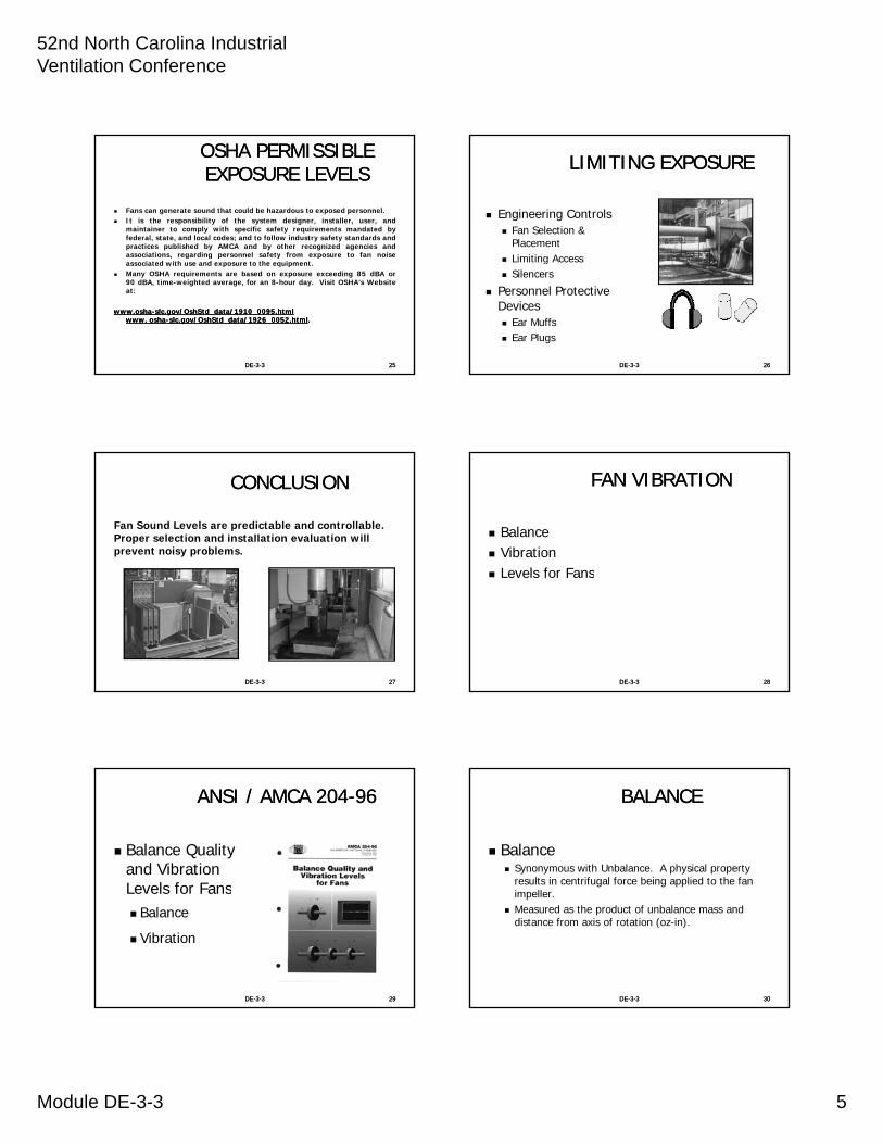
ANSI / AMCA 204ANSI / AMCA 204--9696
Balance Quality and Vibration Levels for FansLevels for Fans Balance
Vibration
DEDE--33--33 2929
BALANCEBALANCE
Balance Synonymous with Unbalance. A physical property
results in centrifugal force being applied to the fan impeller.
Measured as the product of unbalance mass and distance from axis of rotation (oz-in).
DEDE--33--33 3030
52nd North Carolina Industrial Ventilation Conference
Module DE-3-3 6
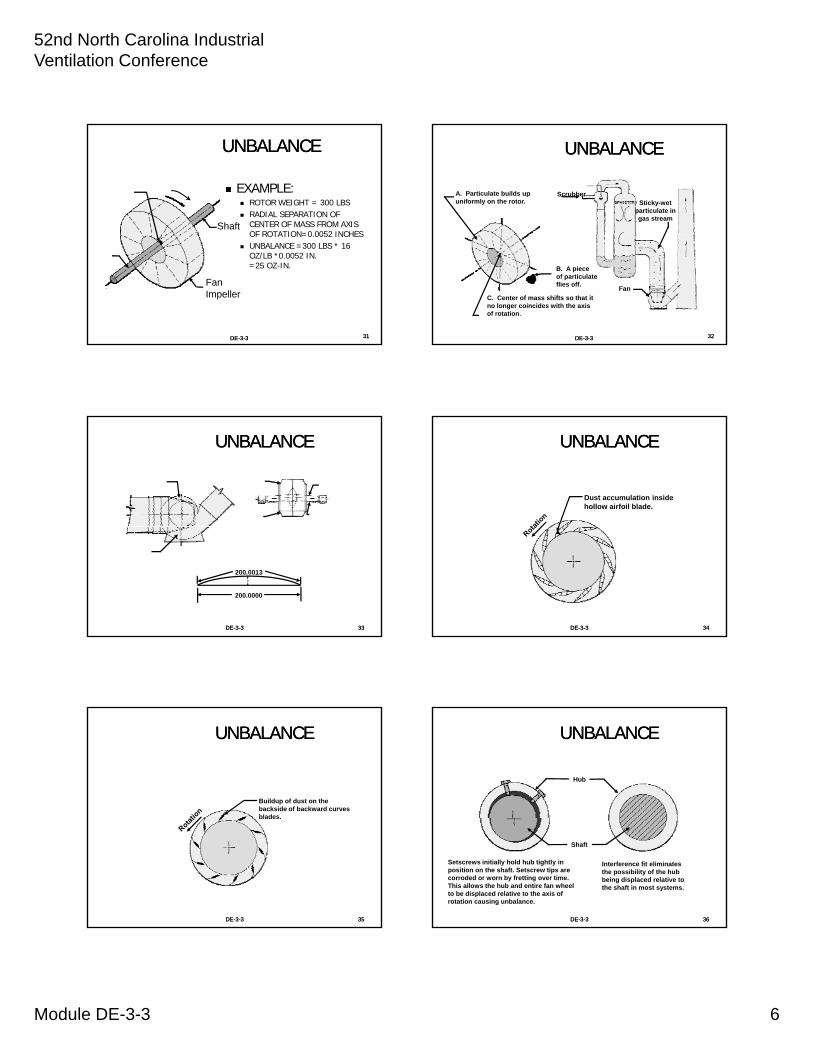
UNBALANCEUNBALANCE
EXAMPLE: ROTOR WEIGHT = 300 LBS RADIAL SEPARATION OF
CENTER OF MASS FROM AXIS OF ROTATION=0 0052 INCHES
ShaftOF ROTATION=0.0052 INCHES
UNBALANCE =300 LBS * 16 OZ/LB *0.0052 IN.=25 OZ-IN.
DEDE--33--33 3131
Fan Impeller
UNBALANCEUNBALANCE
A. Particulate builds up uniformly on the rotor.
ScrubberSticky-wet
particulate in gas stream
DEDE--33--33
B. A piece of particulate flies off.
C. Center of mass shifts so that it no longer coincides with the axis of rotation.
Fan
3232
UNBALANCEUNBALANCE
DEDE--33--33 3333
200.0013
200.0000
UNBALANCEUNBALANCE
Dust accumulation inside hollow airfoil blade.
DEDE--33--33 3434
UNBALANCEUNBALANCE
Buildup of dust on the backside of backward curves blades
DEDE--33--33 3535
blades.
UNBALANCEUNBALANCE
Hub
DEDE--33--33 3636
Shaft
Setscrews initially hold hub tightly in position on the shaft. Setscrew tips are corroded or worn by fretting over time. This allows the hub and entire fan wheel to be displaced relative to the axis of rotation causing unbalance.
Interference fit eliminates the possibility of the hub being displaced relative to the shaft in most systems.

52nd North Carolina Industrial Ventilation Conference
Module DE-3-3 7
EFFECT OF TEMPERATURE EFFECT OF TEMPERATURE CHANGECHANGE
Fan impeller initially operating at 70 F.Process gas temperature increases rapidly.
Weld
Fan impeller and hub heat up more quickly than the shaft
Integral hub and shaft for very rapid temperature change
DEDE--33--33
than the shaft. temperature change applications.
Conclusion: Initial interference fit should be in
excess of 0.002 inches to allow for thermal expansion plus an allowance for hub expansion due to centrifugal force.
Example: Shaft dia. = 3.9375 in. Hub average temp = 215 F Shaft average temp =80 F Then hub growth relative to shaft: (3.9375) * (80) * (6.5E-6) = 0.002
in. Fan impeller weight = 250 lbs.. (250 lbs. x 16 oz/lb. x 0.002
inches) Resulting unbalance = 8.0 oz-inches
3737
ANSI / AMCA 204, TABLE ANSI / AMCA 204, TABLE 44--11
Table 4-1 Fan Application Categories
APPLICATION EXAMPLESDRIVERPOWERkW (HP)LIMITS
FANAPPLICATIO
NCATEGORY,
BV
RESIDENTIAL Ceiling fans, attic fans,window AC
<= .15 (0.2)>.15 (0.2)
BV-1BV-2
HVAC &AGRICULTURAL
Building ventilation andair conditioning;
<=3.7 (5.0)>3 7 (5 0)
BV-2BV-3
DEDE--33--33 3838
AGRICULTURAL air conditioning;commercial systems
>3.7 (5.0) BV-3
INDUSTRIALPROCESS& POWERGENERATION, ETC.
Baghouse, scrubber,mine, conveying, boilers,combustion air, pollutioncontrol, wind tunnels
<=300(400)
>300 (400)
BV-3BV-4
TRANSPORTATION &MARINE
Locomotives, trucks,automobiles
<= 15 (20)> 15 (20)
BV-3BV-4
TRANSIT/TUNNEL Subway emergencyventilation, tunnel fans,garage ventilation,Tunnel Jet Fans
<=75 (100)> 75 (100)
ANY
BV-3BV-4BV-4
PETROCHEMICALPROCESS
Hazardous gases,process fans.
<= 37 (50)> 37(50)
BV-3BV-4
COMPUTER CHIPMANUFACTURE
Clean room ANY BV-5
ANSI / AMCA 204, TABLE 5ANSI / AMCA 204, TABLE 5--11
T a ble 5 -1
F ANAP P LIC AT IO N
C AT E G O R Y
BALA N C E Q U ALIT YG R AD E
F O R R IG IDR O T O R S /IM P E LLE R
BV -1 * G 1 6
B V 2 G 1 6
DEDE--33--33 3939
B V -2 G 1 6
B V -3 G 6 .3
B V -4 G 2 .5
B V -5 G 1 .0
*N ote : In F A N AP P LIC A T IO N C AT E G O R Y
B V -1 the re m a y be som e e xtre m e ly sm a llfa n rotors we ighing le ss tha n 2 2 7 gra m s (8ounce s) . In such ca se s, re sidua l unba la ncem a y be difficult to de te rm ine a ccura te ly.T he fa brica tion proce ss m ust e nsurere a sona bly e qua l we ight distribution a boutthe a xis of rota tion.
ANSI / AMCA 204, APPENDIX C.2ANSI / AMCA 204, APPENDIX C.2
DEDE--33--33 4040
VIBRATIONVIBRATION
Vibration The alternating mechanical motion of an elastic
system, components of which are amplitude, frequency and phase.
In general practice vibration values are reported as: Displacement - mils Velocity - inches/second Acceleration - peak g’s
DEDE--33--33 4141
VIBRATION VELOCITYVIBRATION VELOCITY1780 RPM1780 RPM
UU������
� 12�72 ��� 12�72 ��������
DEDE--33--33 4242
M������ V��������M������ V��������
��� ���� ��������� ���� ������
�2�5 �������2�5 ������
��� 0�10 ���������� 0�10 �������

52nd North Carolina Industrial Ventilation Conference
Module DE-3-3 8
VIBRATIONVIBRATION
Note that the bearing housing is considerably lower than the expected vibration of the rotor in free space.
V��������V��������
P�����P�����
M������ BM������ B
������ H������� H�
����������
S���� D�������� S���� D��������
L���� R����L���� R����
DEDE--33--33 4343
H��� S����H��� S����
���� P������� P���
��������
SLEEVE BEARINGSLEEVE BEARINGP�������� P���� �������� P�������� P���� ��������
����� ������� �������� ����� ������� ��������
�������� �� ��� ������� �������� �� ��� �������
����������������S���� S����
��������������������
DEDE--33--33 4444
B������ H������B������ H������
B������ L���� B������ L����
����������������
O�� F��� O�� F���
�������� ������������� �����
EFFECT OF STRUCTUREEFFECT OF STRUCTUREFan Mass Mass
Cyclic Forces
Structural Steel
DEDE--33--33 4545
Circus FlagpoleAcrobat
Flagpole acts asa spring
Fn = 30 cyc/min
Structural Steelacts as a springFn = 1200 cyc/minFan operating
speed = 1180RPM
Foundation
SOLID FOUNDATIONSOLID FOUNDATION
0 8
1.0
1.2
1.4
1.6N����� N�����
F� � 1680 �������F� � 1680 �������
O�������� ����� O�������� �����
�F��F�
���
���
���
���
DEDE--33--33 4646
0.0
0.2
0.4
0.6
0.8
0 500 1000 1500 2000
0�10 ������0�10 ������
11801180
S���� �RPM�S���� �RPM�
F� �1�4 � FF� �1�4 � F
V�����
V�����
�����
�����
STRUCTURAL STEEL MOUNTINGSTRUCTURAL STEEL MOUNTING
1.2
1.4
1.6
N����� N�����
F� � 1200 �������F� � 1200 �������
0�70 ������0�70 ������
O�������� ����� O�������� �����
�F��F�
��
��
��
��
0.0
0.2
0.4
0.6
0.8
1.0
0 500 1000 1500 2000
DEDE--33--33 4747
11801180
S���� �RPM�S���� �RPM�
V������
V������
������
������
FLEXIBLE MOUNTFLEXIBLE MOUNTE�������� E��������
J����J����
E�������� E��������
J����J����D��������
D���
DEDE--33--33 4848
I����
D���R���� S��R���� S����B���B���
�O���� �������� ��������O���� �������� �������
S����� I�������� ���� ������ S����� I�������� ���� ������
���������� �� 1�0 ���������������� �� 1�0 ������
F� � 187�7�1F� � 187�7�1�5�5 �187�7 ��������187�7 �������S��������� S���� P�S��������� S���� P�
������������

52nd North Carolina Industrial Ventilation Conference
Module DE-3-3 9
ANSI / AMCA 204, TABLE 6ANSI / AMCA 204, TABLE 6--33
Table 6-3 Seismic Vibration Limits for Tests Conducted in the Factory
Values shown are peak velocity, mm/s (inches/s),Filter-In, at the factory test speed.
FANAPPLICATION
CATEGORY
RIGIDLYMOUNTEDmm/s (in./s)
FLEXIBLYMOUNTEDmm/s (in./s)
BV-1 12.7 (0.50) 15.2 (0.60)
BV-2 5.1 (0.20) 7.6 (0.30)
BV-3 3.8 (0.15) 5.1 (0.20)
BV-4 2.5 (0.10) 3.8 (0.15)
BV-5 2.0 (0.08) 2.5 (0.10)
DEDE--33--33 4949
VIBRATION UNITSVIBRATION UNITS
DEDE--33--33 5050
TRANSDUCER MOUNTINGTRANSDUCER MOUNTING
V�������V�������
A����A����
SWSI Centrifugal Fans
DEDE--33--33 5151
H���������H���������
TRANSDUCER MOUNTINGTRANSDUCER MOUNTING
V�������V�������
A����A����
DEDE--33--33
DWDI Centrifugal Fans
H���������H���������
5252
TRANSDUCER MOUNTINGTRANSDUCER MOUNTING
A����A����H���������H���������
V������V������
��
DEDE--33--33
Axial Fans
V�������V�������
5353
VIBRATION SPECTRUMVIBRATION SPECTRUM
0�150�15
0�200�20
F����� F�����
I�I�
����
����
�����
�����
F����� O��F����� O��
DEDE--33--33 5454
0�000�00
0�050�05
0�100�10
00 500500 10001000 15001500 20002000 25002500
S���� �RPM�S���� �RPM�
V���
V���
�I���
�I���
52nd North Carolina Industrial Ventilation Conference
Module DE-3-3 10
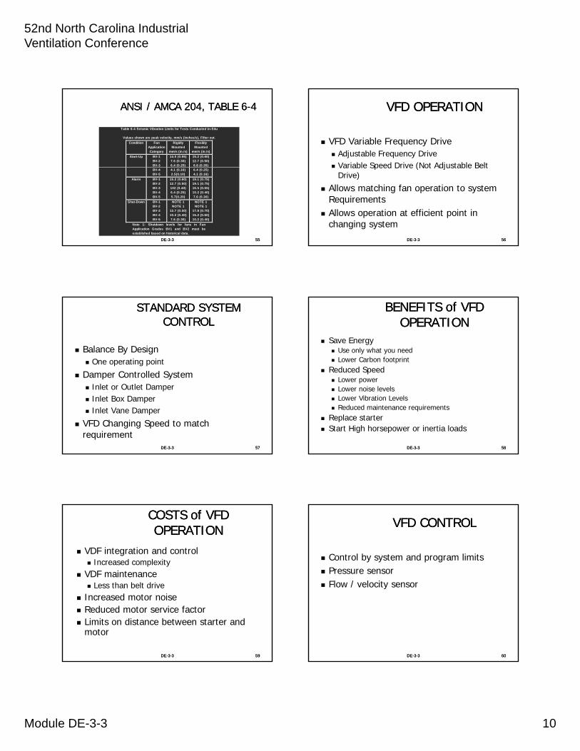
ANSI / AMCA 204, TABLE 6ANSI / AMCA 204, TABLE 6--44
Table 6-4 Seismic Vibration Limits for Tests Conducted In-Situ
Values shown are peak velocity, mm/s (inches/s), Filter out.
Condition FanApplicationCategory
RigidlyMounted
mm/s (in./s)
FlexiblyMounted
mm/s (in./s)
Start-Up BV-1BV-2BV-3
14.0 (0.55)7.6 (0.30)6.4 (0.25)
15.2 (0.60)12.7 (0.50)8.8 (0.35)
BV-4BV-5
4.1 (0.16)2.5(0.10)
6.4 (0.25)4.1 (0.16)
Alarm BV-1BV-2BV-3BV-4
BV-5
15.2 (0.60)12.7 (0.50)102 (0.40)6.4 (0.25)
5.7(0.20)
19.1 (0.75)19.1 (0.75)16.5 (0.65)10.2 (0.40)
7.6 (0.30)
Shut-Down BV-1BV-2BV-3BV-4BV-5
NOTE 1NOTE 1
12.7 (0.50)10.2 (0.40)7.6 (0.30)
NOTE 1NOTE 1
17.8 (0.70)15.2 (0.60)10.2 (0.40)
Note 1: Shutdown levels for fans in FanApplication Grades BV1 and BV2 must beestablished based on historical data.
DEDE--33--33 5555
VFD OPERATIONVFD OPERATION
VFD Variable Frequency Drive Adjustable Frequency Drive Variable Speed Drive (Not Adjustable Belt Variable Speed Drive (Not Adjustable Belt
Drive)
Allows matching fan operation to system Requirements
Allows operation at efficient point in changing system
DEDE--33--33 5656
STANDARD SYSTEM STANDARD SYSTEM CONTROLCONTROL
Balance By Design One operating point
Damper Controlled System Damper Controlled System Inlet or Outlet Damper Inlet Box Damper Inlet Vane Damper
VFD Changing Speed to match requirement
DEDE--33--33 5757
BENEFITS of VFD BENEFITS of VFD OPERATIONOPERATION
Save Energy Use only what you need Lower Carbon footprint
Reduced Speed Lower power Lower noise levels Lower Vibration Levels Reduced maintenance requirements
Replace starter Start High horsepower or inertia loads
DEDE--33--33 5858
COSTS of VFD COSTS of VFD OPERATIONOPERATION
VDF integration and control Increased complexity
VDF maintenanceL th b lt d i Less than belt drive
Increased motor noise Reduced motor service factor Limits on distance between starter and
motor
DEDE--33--33 5959
VFD CONTROLVFD CONTROL
Control by system and program limits Pressure sensor
Flow / velocity sensor Flow / velocity sensor
DEDE--33--33 6060

52nd North Carolina Industrial Ventilation Conference
Module DE-3-3 11
FAN SELECTIONFAN SELECTION
System Calculation Flow or Capacity
Pressure Requirements
essu
rees
sure
System Resistance Curve
System Losses Plotted
DEDE--33--33 6161
22
CFM x Constant 0.075 x 1097 x Area
CFMC x C
VP
SystemSystemLossLoss
CFMCFM
Pre
Pre
FAN SELECTIONFAN SELECTION
PPrreessss
PPooww
Required SPRequired SP
System CurveSystem Curve
SP vs. CFMSP vs. CFM
DEDE--33--33
Select a fan which will generate the required pressure at the desired airflow.
AirflowAirflow Desired CFMDesired CFM
ssuurree
wweerr
HP vs. CFMHP vs. CFM
6262
THE FAN LAWSTHE FAN LAWS
The Fan Laws are used to calculate fan performance at:Other Speeds, Other Densities, Other Fan Sizes
First Law:First Law:
2
3
212 RPM
RPM
DIA
DIACFMCFM
DEDE--33--33 6363
First Law:First Law:
11
12 RPMDIA
Second Law:Second Law:
1
2
2
1
2
2
1
212
RPM
RPM
DIA
DIASPSP
Third Law:Third Law:
1
2
3
1
2
5
1
212
RPM
RPM
DIA
DIAHH
THE FAN LAWSTHE FAN LAWS
PPrreess
PPoo
DEDE--33--33
ssuurree
wweerr
AirflowAirflow Changes in Speed
6464
VFD POWER SAVINGSVFD POWER SAVINGS
3
RPM
Power varies as the cube of the change in speed ratio.
)3/1(
old
newoldnew
old
newoldnew
HP
HPRPMRPM
RPM
RPMHPHP
DEDE--33--33 6565
FAN SELECTIONFAN SELECTION
Interaction of Fan Performance Curve and System Curve There is only one intersection between the fan curve and system
curve. Fans are load matching devices.
DEDE--33--33 6666
PPrreessssuurree
PPoowweerr
AirflowAirflow
52nd North Carolina Industrial Ventilation Conference
Module DE-3-3 12
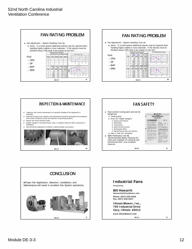
FAN RATING PROBLEMFAN RATING PROBLEM
Fan Adjustment – System Handling Toxic Air Given: In a hood system additional velocity may be required when
handling highly volatile or toxic materials. If the velocity must be doubled using a VFD what is the impact on the fan?…
Req CFM Req SP Req BHP Req RPMRequired Fan Performance
Fan Performance Curve2.5 1.2
DEDE--33--33
Find: – CFM– SP– BHP– RPM
Point Flow Pressure Power Speed 238.3656 3
1 0
2 63
3 136
4 251
5 1006
Act CFM Act SP Act BHP Avg RPM
240 1.65 4.8 1,793Point Flow Pressure Power Speed
1 0 1.8 2.6 1,7162 95 2.3 3.5 1,7133 191 2.0 4.3 1,7114 286 1.3 5.2 1,7075 429 0.2 6.1 1,702
0.0
0.5
1.0
1.5
2.0
2.5
0 100 200 300 400
Flow (CFM)
Pre
ss
ure
(in
WG
)
0.00.20.40.60.81.01.2
Fan Performance Curv e
0.0
0.5
1.0
1.5
2.0
2.5
0 100 200 300 400 500F low ( C F M )
0.0
1.5
3.0
4.5
6.0
7.5
6767
FAN RATING PROBLEMFAN RATING PROBLEM Fan Adjustment – System Handling Toxic Air
Given: In a hood system additional velocity may be required when handling highly volatile or toxic materials. If the velocity must be doubled using a VFD what is the impact on the fan?…
Find:Req CFM Req SP Req BHP Req RPM
480 6.6 9.1 1,701
Required Fan Performance Fan Performance Curves
3.0
6 0
7.0
DEDE--33--33
Find: – CFM– SP– BHP– RPM
,Point Flow Pressure Power Speed
1 0 1.8 2.6 1,7082 95 2.3 3.4 1,7053 190 2.0 4.3 1,7034 285 1.3 5.1 1,6985 427 0.2 6.0 1,693
Act CFM Act SP Act BHP Avg RPM
422 3.3 10.7 1,793Point Flow Pressure Power Speed
1 0.1 2.0 3.0 1,8002 100 2.5 4.0 1,7973 200 2.2 5.0 1,7954 300 1.4 6.0 1,7905 450 0.2 7.0 1,785
0.0
0.5
1.0
1.5
2.0
2.5
3.0
0 200 400 600
0.01.02.03.04.05.06.07.08.0
0.0
0.5
1.0
1.5
2.0
2.5
0 200 400 600
0.0
1.0
2.0
3.0
4.0
5.0
6.0
6868
INSPECTION & MAINTENANCEINSPECTION & MAINTENANCE
Inspection and routine maintenance on a periodic schedule of fan equipment is necessary.
Historical records of fan condition and maintenance should be maintained and compared with current conditions as they are indicators of upcoming problems.
Monitor and record vibration levels. Sudden changes in fan performance, noise, or vibration levels are often a precursor to
breakdownbreakdown. Fans should be inspected for condition, material buildup, and erosion.
DEDE--33--33 6969
FAN SAFETYFAN SAFETY
Fans contain moving parts and can be dangerous. Install guards. Know the “Hidden Dangers”
Suction and Pressure Windmilling
T t Temperature Noise and Environment Stroboscopic Effect Special Purpose Fans and Systems
Have a “lock out” procedure. AMCA Publication 410-96,
"Recommended Safety Practices For Users and Installers of Industrial and Commercial Fans" is an excellent resource.
DEDE--33--33 7070
CONCLUSIONCONCLUSION
Proper Fan Application, Selection, Installation, and Maintenance will result in excellent Fan System operations.
DEDE--33--33 7171
Industrial FansPresented by
Bill Howarthbhowarth@Illinoisblower [email protected]
Phone: (847) 639-5500Fax: (847) 639-9527
Illinois Blower, Inc., 750 Industrial DriveCary, Illinois 60013www.illinoisblower.com
7272DEDE--33--33

52nd North Carolina Industrial Ventilation Conference
Module DE-3-3 13
7373DEDE--33--33


