
The World Leader in High-Performance Signal Processing Solutions
Inertial Sensors in
GPS & Navigation Systems
Amsterdam, Dec. 15, 2006Amsterdam, Dec. 15, 2006Amsterdam, Dec. 15, 2006Amsterdam, Dec. 15, 2006
Christoph Wagner
Field Applications Specialist Sensors
+49 (89) 76903-349
2
Inertial Sensors in GPS & Navigation Systems Outline
� Introduction
� Basics
� Gyroscopes
� How it works
� Where we are
� Where we go to
� Low-g Accelerometers
� What they are used for in GPS and Nav Systems
� ADIS...
� ...
3
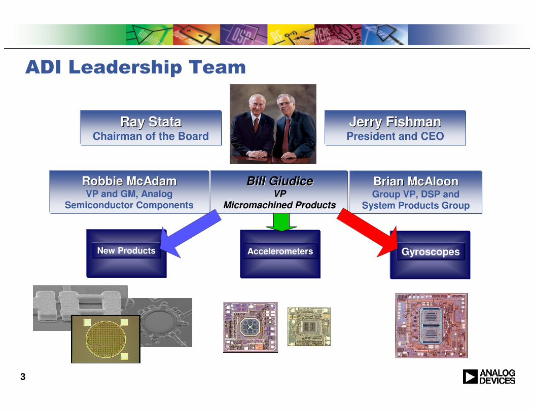
ADI Leadership Team
Brian McAloonBrian McAloonGroup VP, DSP and
System Products Group
Robbie McAdamRobbie McAdamVP and GM, Analog
Semiconductor Components
Bill GiudiceBill GiudiceVP
Micromachined Products
Jerry FishmanJerry FishmanPresident and CEO
Ray StataRay StataChairman of the Board
New Products GyroscopesAccelerometers

4
ADI Micromachined Products DivisionCredentials
� World Class MEMS operation
� 18 Years of Experience in Design and Manufacturing
� Dedicated Facilities in Cambridge, Massachusetts, USA
� 300+ Employees
� QS-9000 and TS16949 Certified
� Most Comprehensive Product Portfolio of any MEMS Manufacturer
� Reliable Supplier to Hundreds of Customers Worldwide
� Top Quality, Reliability and Repeatability Track Record
� >>1 Million Inertial Sensors Shipped Each Week
� >>250M Total Sensors Shipped
Price Yield VolumePPM OTD
Lowest Total Cost of Ownership
0
10
20
30
40
50
60
70
1995
1996
1997
1998
1999
2000
2001
2002
2003
2004
2005
2006
ADI Fiscal Year
0
50
100
150
200
250
300
350
Annual Forecast Cumulative

5
What are we talking about?Newton´s Law
� Force F = Mass m · acceleration a
� Force F = spring constant k · displacement x
���� a = k/m · x
a
mx
m
k
6
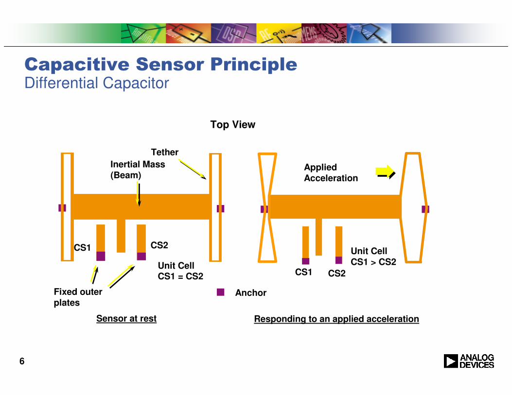
Top View
Tether
Inertial Mass (Beam)
CS1
Anchor
Sensor at rest
Unit CellCS1 = CS2
Fixed outer plates
CS2
Capacitive Sensor PrincipleDifferential Capacitor
Applied Acceleration
Unit Cell CS1 > CS2
CS2
Responding to an applied acceleration
CS1
7
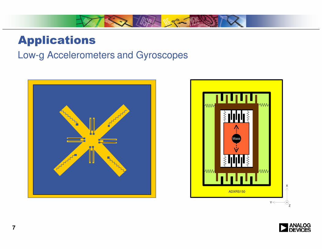
Applications
ZY
X
ADXRS150
Mass
Low-g Accelerometers and Gyroscopes
8
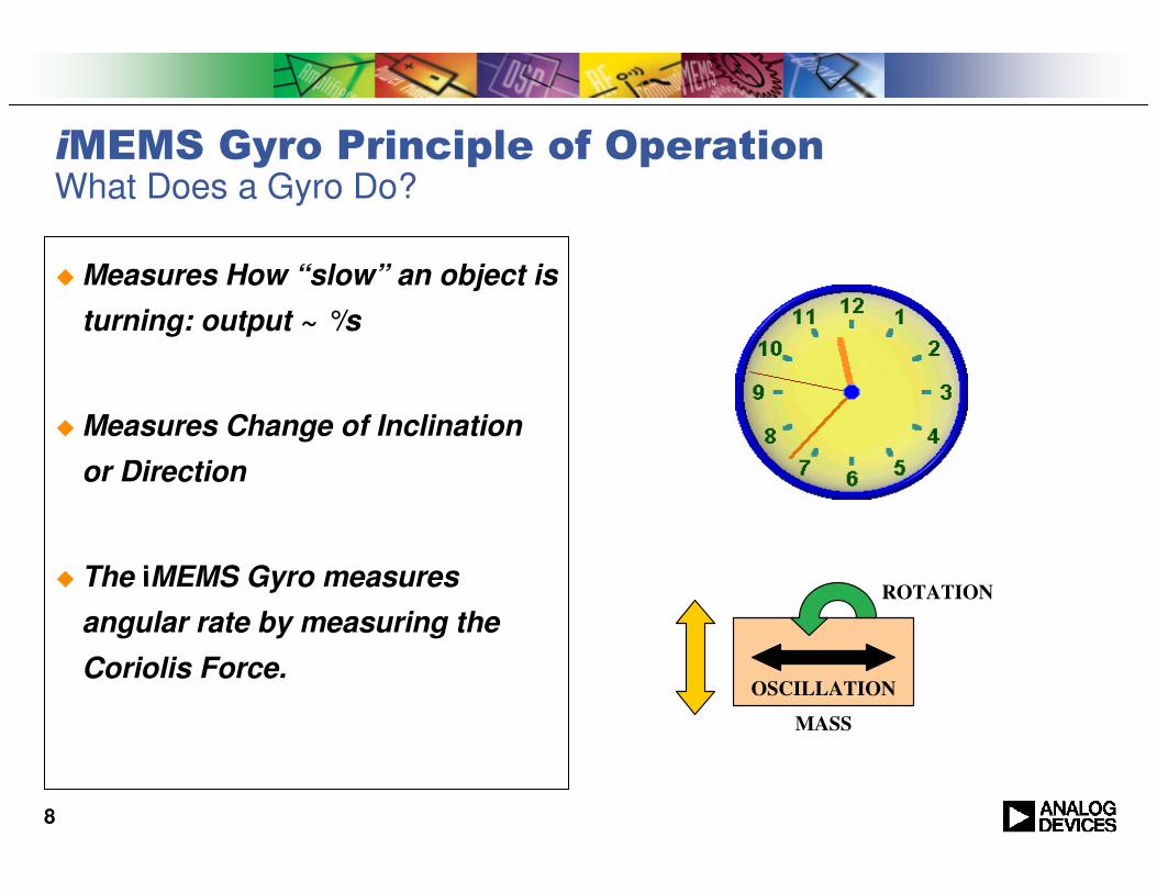
iMEMS Gyro Principle of OperationWhat Does a Gyro Do?
� Measures How “slow” an object is
turning: output ~ °/s
� Measures Change of Inclination
or Direction
� The iMEMS Gyro measures
angular rate by measuring the
Coriolis Force.OSCILLATION
MASS
ROTATION

9
ADI’s Gyros ADXRSxxxPrincipal of Operation
F= 15kHz
x
F= 15kHz
y
Syncronous Demodulation and
Rectification of Y Axis Signal
Low pass filter
& Amplifier
ZY
X
ADXRS150
Mass
Rateout
Drive and Feedback Loop
Coriolis Acceleration
Resonato
r Motio
n
Rotation Axis
Linear - Linear Oscillator

10
iMEMS Gyro Principle of Operation
VibratoryMass
VibratoryMass
Accelerometer
Accelerometer
11
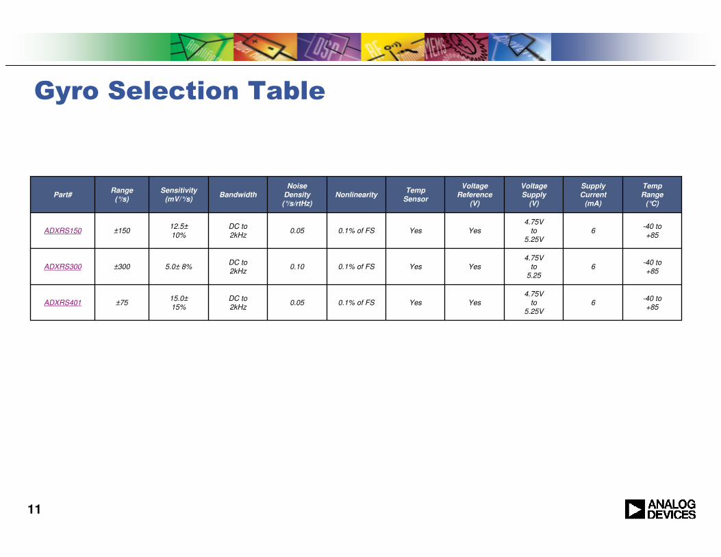
Gyro Selection Table
-40 to+85
64.75V
to5.25V
YesYes0.1% of FS0.05DC to2kHz
15.0±15%
±75ADXRS401
-40 to+85
64.75V
to5.25
YesYes0.1% of FS0.10DC to2kHz
5.0± 8%±300ADXRS300
-40 to
+856
4.75Vto
5.25VYesYes0.1% of FS0.05
DC to
2kHz
12.5±
10%±150ADXRS150
TempRange
(°C)
SupplyCurrent
(mA)
VoltageSupply
(V)
VoltageReference
(V)
TempSensor
NonlinearityNoise
Density(°/s/rtHz)
BandwidthSensitivity
(mV/°/s)Range
(°/s)Part#

12
Analog Devices’ iMEMS Angular Rate SensorsBackground
� Industry’s first and only volume,single-chip angular rate sensor
� iMEMS process integrates electronics and
mechanical elements for optimal balance of
price and performance
� Volume production since 2002
� Shipping into automotive safety systems
� Rollover Detection and Stability Control
� Shipping into other applications
� Navigation, Consumer, Industrial and Military
� Same iMEMS process used in over 250 million
sensors shipped to date
� World-class quality, reliability and on-time delivery
� Broad product roadmap covering wide range of applications
� Silicon-based iMEMS enables higher levels of integration
13
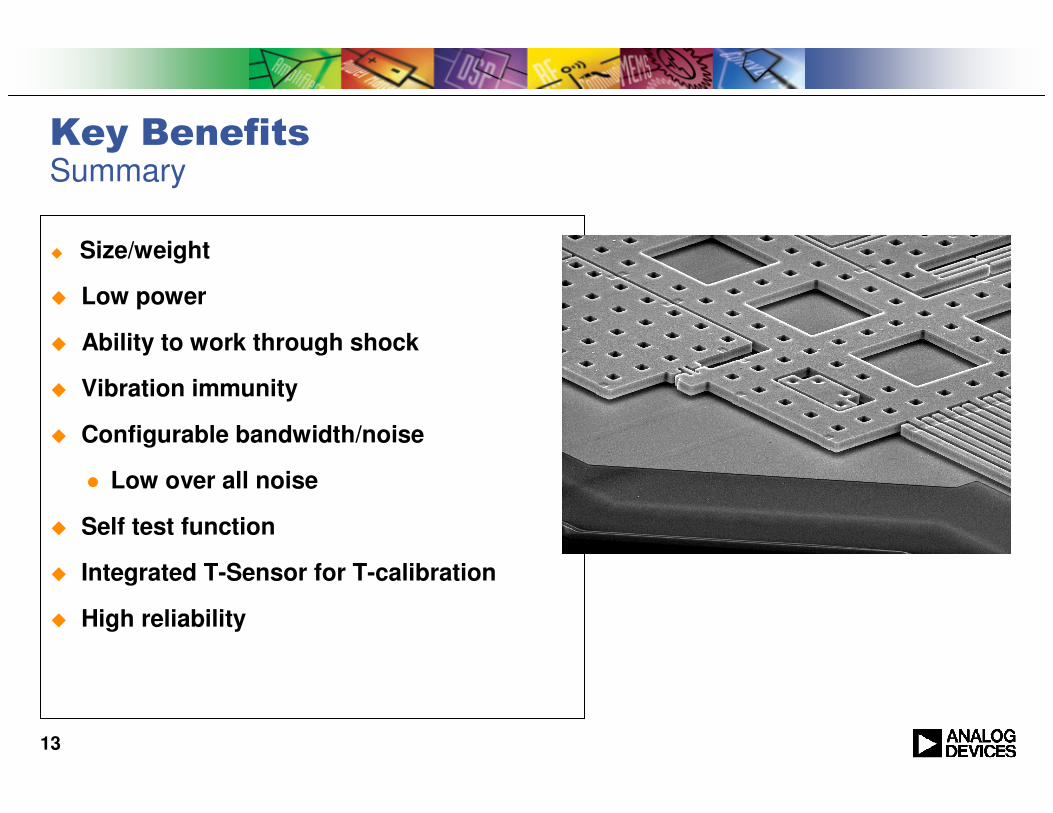
Key BenefitsSummary
� Size/weight
� Low power
� Ability to work through shock
� Vibration immunity
� Configurable bandwidth/noise
� Low over all noise
� Self test function
� Integrated T-Sensor for T-calibration
� High reliability
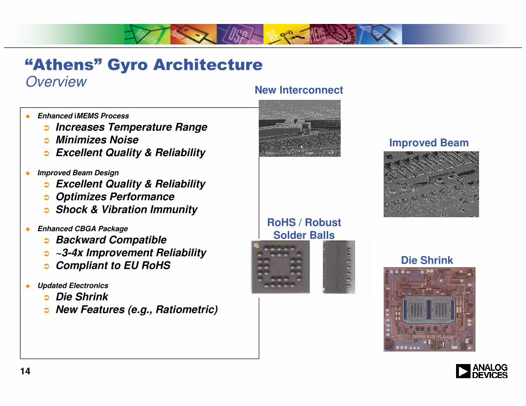
14
� Enhanced iMEMS Process
� Increases Temperature Range
� Minimizes Noise
� Excellent Quality & Reliability
� Improved Beam Design
� Excellent Quality & Reliability
� Optimizes Performance
� Shock & Vibration Immunity
� Enhanced CBGA Package
� Backward Compatible
� ~3-4x Improvement Reliability
� Compliant to EU RoHS
� Updated Electronics
� Die Shrink
� New Features (e.g., Ratiometric)
“Athens” Gyro ArchitectureOverview
New Interconnect
Improved Beam
RoHS / Robust
Solder Balls
Die Shrink
15
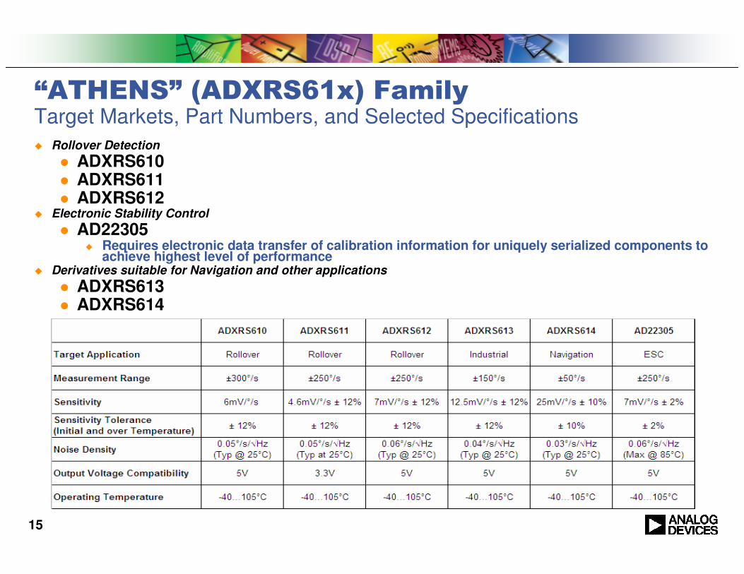
“ATHENS” (ADXRS61x) FamilyTarget Markets, Part Numbers, and Selected Specifications
� Rollover Detection
� ADXRS610� ADXRS611� ADXRS612
� Electronic Stability Control
� AD22305� Requires electronic data transfer of calibration information for uniquely serialized components to
achieve highest level of performance� Derivatives suitable for Navigation and other applications
� ADXRS613� ADXRS614
16
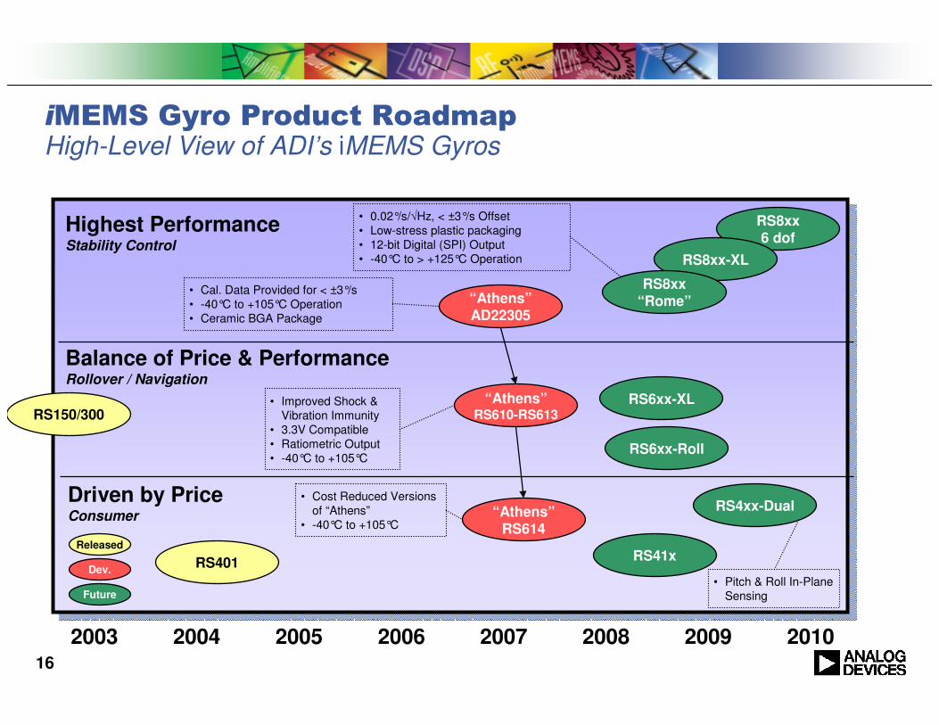
iMEMS Gyro Product RoadmapHigh-Level View of ADI’s iMEMS Gyros
2003
RS150/300
RS401
RS8xx6 dof
RS6xx-XL
RS4xx-Dual
2004 2005 2006 2007 2008 2009 2010
RS41x
Highest PerformanceStability Control
Balance of Price & PerformanceRollover / Navigation
Driven by PriceConsumer
• 0.02°/s/√Hz, < ±3°/s Offset
• Low-stress plastic packaging
• 12-bit Digital (SPI) Output
• -40°C to > +125°C Operation
“Athens”RS610-RS613
• Improved Shock &
Vibration Immunity
• 3.3V Compatible
• Ratiometric Output
• -40°C to +105°CRS6xx-Roll
• Pitch & Roll In-Plane
Sensing
Released
Dev.
Future
“Athens”RS614
• Cost Reduced Versions
of “Athens”
• -40°C to +105°C
“Athens”AD22305
• Cal. Data Provided for < ±3°/s
• -40°C to +105°C Operation
• Ceramic BGA Package
RS8xx-XL
RS8xx“Rome”
17
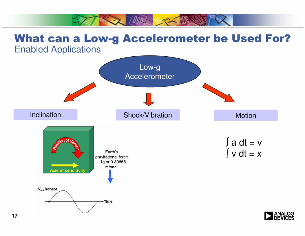
What can a Low-g Accelerometer be Used For?Enabled Applications
Low-gAccelerometer
Inclination Shock/Vibration Motion
∫ a dt = v∫ v dt = x

18
ProductionCP-16-25 to70°
0.18 @ 1.8V
1.8 to 5.252801.6Analog±10300 mV/g±3g2ADXL323
ProductionCP-16-25 to70°
0.18 @ 1.8V
1.8 to 3.6280(X,Y)350(Z)
1.6(XY)0.55(Z)
Analog±10300 mV/g±3g3ADXL330
ProductionCP-16-20 to
70°0.52.4 to 62202.5Analog±10420 mV/g±2g2ADXL322
ProductionCP-16-20 to70°C
0.52.4 to 63202.5Analog±1057 mV/g±182ADXL321
ProductionCP-16-20 to70°C
0.52.4 to 62502.5Analog±10174 mV/g±5g2ADXL320
ProductionE-8-40 to85°C
0.75
(3 to 6)1602.5PWM±1030 %/g±1.2g2ADXL213
ProductionE-8-40 to
125°C0.5
3.3
(3 to 6)1702.5Analog±5620 mV/g±1.7g2ADXL204
ProductionE-8-40 to125°C
0.75
(3 to 6)1102.5Analog±61000 mV/g±1.7g2ADXL203
ProductionE-8-40 to125°C
0.75
(3 to 6)1102.5Analog±61000 mV/g±1.7g1ADXL103
StatusPackageTemp
Range(°C)
Supply
Current(mA)
Voltage
Supply(V)
Noise
Density(µg/rtHz)
**MaxBandWidth(kHz)
OutputType
Sensitivity
Accuracy(%)
SensitivityRange# of
AxesPart#
Accelerometer Selection Tablewww.analog.com -> MEMS and Sensors -> iMEMS® Accelerometers
Further Variants on Request
Automotive / Military / Industrial
Consumer

19
iSensorsAdditional Product Options for Industrial MEMs Customers
� iSensor Product Positioning
� Separate Product Line from ADI’s iMEMs (MPD) Component Group
� Additional Integration and Performance; Calibration; Embedded Compensation; Programmability; Application Focused Features
� Optimized for Industrial and Instrumentation Customers
� Enable Low Cost of Entry, and Fast Time to Market

20
iSensor Family: Current Products and Developments
Product
Category
Fully Integrated,
Digital Multi-Sensor
Programmable,
Calibrated
High Performance,
New Function Wireless
Level of
Integration
Inertial and Temp
Sensors, Conversion
Sensor, Conversion,
Embedded Control
Multiple Sensors,
Embedded Control,
Advanced
Architectures
Sensor, Conversion,
Wireless Link
Functionality
Offered
Simple Interface; Full
Signal Chain
Performance
Programmable Sensor;
Application-Targeted
Low Noise; Multi-Axis;
Application Targeted Remote Sensing
Part
Numbers
ADIS16003,
ADIS16006,
ADIS16100,
ADIS16080
ADIS16201, ADIS16202,
ADIS16203, ADIS16204,
ADIS16209, ADIS16250,
ADIS16255
ADIS16120,
ADIS16130,
ADIS1622X,
ADIS16350 ADIS16270
ReleasedSamplingIn DevelopmentIn Definition
16003/6: SPI Accel
16100/80: SPI Gyro
16201: Prog. Inclinometer
16203: 360o Inclinometer
16209: Hi-Accuracy Inclinometer
16120/130: Low Noise Gyro
16250/5: Prog. Gyro
16202: Wide-BW Prog. Accel
16204: Hi-G Prog. Accel / Impact Sensor
1622X: Vibration Sensor
16350: 3-axis gyro
16270: Wireless Monitor
Product Descriptions
21
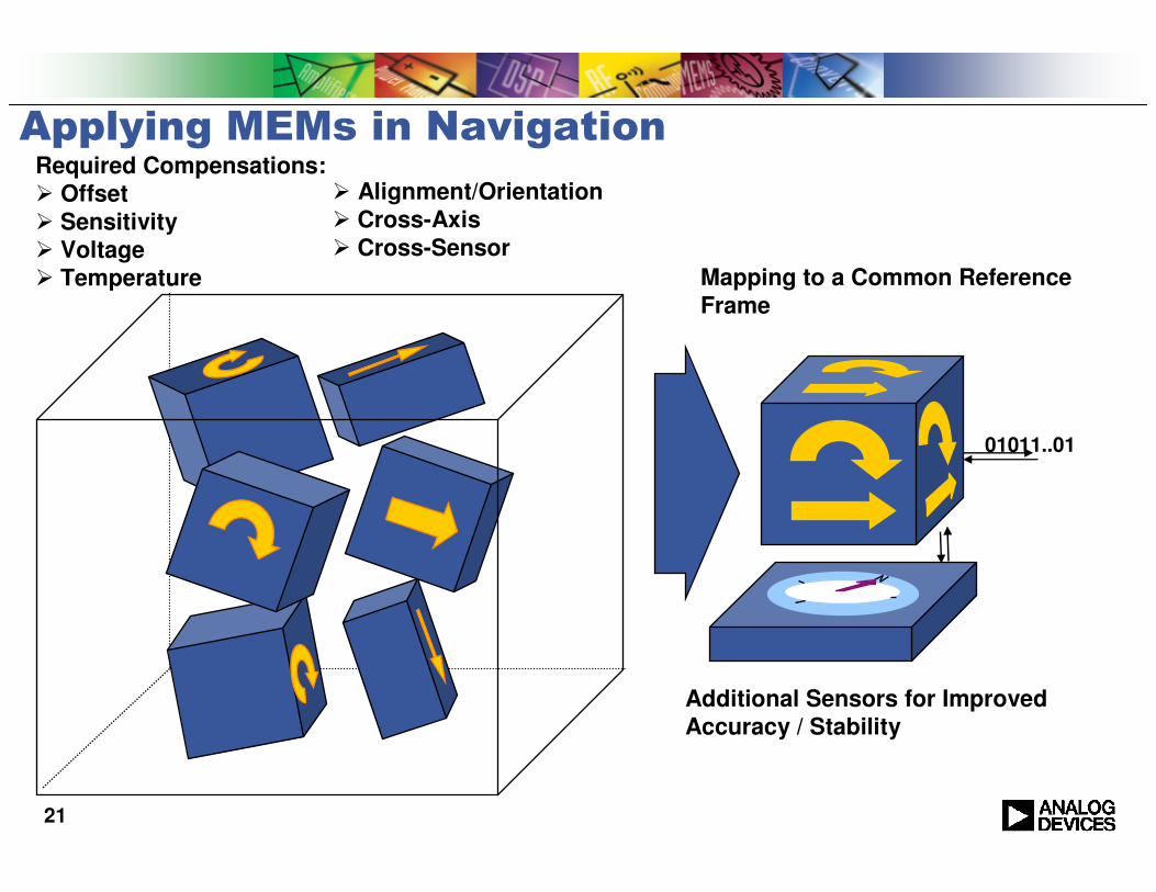
01011..01
Applying MEMs in NavigationRequired Compensations:
� Offset
� Sensitivity
� Voltage
� Temperature Mapping to a Common Reference
Frame
Additional Sensors for Improved
Accuracy / Stability
� Alignment/Orientation
� Cross-Axis
� Cross-Sensor

22
ADIS16350 TriTriTriTri----Axis GyroAxis GyroAxis GyroAxis Gyro (Preliminary)
KEY FEATURESKEY FEATURESKEY FEATURESKEY FEATURESKEY FEATURESKEY FEATURESKEY FEATURESKEY FEATURES� Tri-Axis Gyroscope
� +/- 320o/sec range� 14-bit resolution
� Tri-axis Accelerometer� +/-10g range� 14-bit resolution
� 350Hz Bandwidth� Factory Calibrated Sensitivity and Bias� Digitally controlled Sensitivity and Bias� Digitally controlled Sample Rate� Digitally controlled filtering� Programmable condition monitoring,
alarms� Auxiliary digital I/O� Digitally activated self-test� Programmable Power Management� Embedded Temperature Sensor� SPI Compatible serial interface� Auxiliary 12-bit ADCinput and DAC
output� Single supply operation: +4.75V to
+5.25V� 2000g powered shock survivability
� Guidance & Control
� Platform Control & Stabilization
� Inertial Measurement Units
� Motion Control & Analysis
� Robotics
Applications
Schedule
Samples 4Q06
In Run Bias Stability.016
o/sec
Turn-on to Turn-on Bias Stability .035 o/sec
Angular Random Walk 3.6 o/√hr
Calibrated Rate Sensor Cluster
Axial Alignment 1o

23
In Run Bias StabilityRoot Allen Variance
σ τ( )1
2 m 1( ).
1
m 1
i
y i 1( ) y i( )( )2
=
. for m successive y(i) averaged over τ
Depending on averaging time resolution decreases to below 100°/s
AD22305: Typical Root Allan Variance at 25°C vs. Averaging Time
24
Interesting Facts
� Sensor “mass” is 8 micrograms
� Resolution: 100°/h or 0.03°/s
� Equivalent Res.: 37.5 Fermi (1 Fermi = 10-15 m)
� Equivalent Res.: 12 zF (1 zepto F = 10-21 F)

The World Leader in High-Performance Signal Processing Solutions
Thank You!


