

22
Ing. G. Orsello
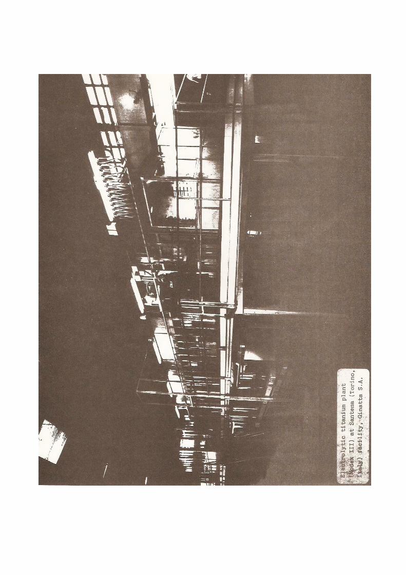
Elettrochimica Marco Ginatta
INDUSTRIAL PLANT FOR THE PRODUCTION OF ELECTROLYTIC TITANIUM.
GINATTA TECHNOLOGY
Summary
Electrowon titanium has reached industrial commerci alization.
In this paper we review the development stages whic h permitted
the realization of the electrowinning plant.
Our first electrolytic industrial pilot plant ("Mod ex I") was
built in 1980. It was succeeded by a second plant ( Modex II) in
1983, and in 1986 we constructed the plant presentl y in
operation (Modex III), which has a nominal capacity of 70 ton
of titanium per year.
The core of the plant is its extraction module ("Mo dex") which
comprises a chamber and a pre-chamber with controll ed
atmospheres and ancillary equipment. The interior o f the
chamber is horizontally divided by removable covers into two
parts. The lower part contains the electrolytic cel ls operating
at temperatures up to 950°C and with current intens ities
attaining 50,000 A. In the upper part, operating at
temperatures of 100 to 120°C, an hydraulic manipula tor handles
the electrodes and allows a continuous mode of prod uction.
The overall operation of the plant has a simplicity comparable
to that of aqueous solution tankhouses.
In comparison with other present processes and plan ts for the
production of titanium, the metal produced by a Gin atta plant
has the advantages of lower costs and higher qualit y.
Costs are lower mostly because of: a) lower overall energy
consumption; b) lower labour requirements due to th e continuous
character of the process and its high degree of aut omation; c)
high rate of throughput; d) lower capital costs.

23
Introduction
The literature on electrolytic cells for the produc tion of
titanium from molten salts is quite extensive.
Although some of the associated developments reache d the pilot
plant stage, the lack of specifically designed hard ware has not
allowed their full exploitation at the commercial s cale.
Important examples of this state of affairs are pro vided by the
activities of the U.S. Bureau of Mines (1-2), and o f Companies
such as New Jersey Zinc (3), Timet (4), Cezus (5) a nd D-H
Titanium (6).
The Ginatta electrolytic plant was specifically des igned and
constructed for titanium.
Our development work started from experimental stud ies (7-9) in
prototype cells. The results confirmed that the ele ctrolytic
production of reactive metals is difficult to maint ain in
small, closed cells for any length of time of indus trial
significance. Clearly, too many tasks and functions were
assigned to too few general-purpose components, oft en with
conflicting specifications.
The main recurring problems were:
− mechanical strength of the equipment at working tem pe-
rature;
− corrosion of materials;
− handling of the cathodes for the continuous operati on of
the process;
− accurate data logging for all process parameters.
Our goal was to design a plant which overcomes thes e problems.
In this paper we describe and illustrate the hardwa re which
allows an easy operation of the process.
Description of the process
The raw material fed into the electrolytic plant is titanium
tetrachloride.

24
It dissolves in the electrolyte in the Dissolution Cell (10)
according to the reaction :
TiCl 4 -> TiCl 2 + Cl 2
The electrolytic titanium is deposited on cathodes in the
Extraction Cell according to the reaction:
TiCl 2 -> Ti + Cl 2
The Dissolution Cell is separated from the Extracti on Cell.
Their common electrolyte (Sodium-Titanium-Chloride) circulates
in closed circuit.
The cells have Heterogeneous Bipolar Electrodes, ge nerating a
high titanium tetrachloride dissolution rate in the electrolyte
and a low average valence of the titanium species d issolved.
They maintain, at a steady state, a very low activi ty of
titanium chlorides in the insoluble anodes electrol yte volume
(anolyte).
The operating temperature (830°C) results in:
− Low drag out.
− High current density.
− High titanium concentration in the electrolyte.
The electrolyte is inexpensive (NaCl technical grad e) and easy
to handle.
Description of the plant
The present design of our electrolytic plant (11) h as enabled
us to achieve the ease of operation of an aqueous s olution
tankhouse.
The plant we needed was to be characterized by high versatility
and was to enable us to make electrochemical measur ements and
obtain samples under reproducible and steady state conditions
of real industrial conditions.

25
Our Modex III plant has the flexibility required fo r the
performance of long runs and for the rapid changes of many key
parameters: cell configurations, types of electrode s,
electrolyte chemistry, working temperatures, pressu res and
compositions of the gas atmosphere, current densiti es and
voltages.
The plant is the result of a design integrating man y
components, each one specializing in a specific fun ction.
The main tasks of the Modex plant are:
− providing an inert atmosphere in the electrolytic c ell;
− melting the electrolyte and keeping the electrolyti c cell
at the working temperature;
− allowing energy and mass transfer between the elect rolytic
process and the exterior;
− controlling the process.
The Modex plant comprises:
− the external shell, formed by a chamber and a pre-c hamber;
− the electrolytic cell, inside the chamber;
− the removable covers of the cell;
− a structure for supporting the electrodes and feedi ng
electric current to them;
− the electrodes;
− the hydraulic manipulator, which performs the handl ing of
the electrodes as well as maintenance and ancillary
operations.
The Shell
The shell provides a protected environment in which the
titanium electrolytic process can be operated in op en cells.
The pre-chamber has the purpose of transferring mat erial from
the Modex to the exterior under a controlled atmosp here.
Windows allow vision inside the chamber and into th e cells.
Consequently, the electrodes can be photographed du ring the
operation, and reference and standard electrodes ca n be exactly
positioned for accurate measurements.

26
The Cell
Departing from the traditional designs, the Cell he re has only
one function, i.e. to contain the molten electrolyt e. Gas
tightness is assured by the shell.
This results in two very important operative advant ages; the
process can be run:
− at higher temperatures, and
− under negative pressure.
The Cell has been entirely built with carbon steel, the latter
being quite compatible with the electrolytes of tit anium
production. The structural weakness of the cell at operating
temperature has been overcome by refractories suppo rting the
outside of the Cell.
The Cell is rectangular, a geometry typical of aque ous
electrolytic plants (such as Pb, Zn, Cu...) and pla ced inside
an electric furnace. To avoid corrosion and impurit ies, heaters
and refractories are not in contact with the gases generated by
the electrolysis. On start-up of the plant, the fur nace melts
the electrolyte. The current for electrolysis keeps the Cell at
the operating temperature, but the furnace allows t o test other
working temperatures.
The Electrodes
The assembly of the electrodes is such that each on e has an
independent electric control and can be easily repl aced.
The harvesting of the cathodes allows for the produ ction to be
continuous. In the Modex III Extraction Cell there are six
cathodes, each one having a total immersed surface of two
square meters.
Good electric contact is provided by the weight of the
electrode on the couple of feeding bars; the shape of the
contact ensures its cleanliness and a negligibly sm all junction
voltage drop.

27
Bearing bars are fed by high intensity-low voltage electric
feedthroughs, across the shell.
Busbars connect the feedthroughs to rectifiers.
Ancillary Equipment
All power-mechanisms of our Modex III use proportio nal
hydraulics, that proved to be very reliable.
The main movements are associated with the two pre- chamber
ports, the removable covers of the cell which therm ally
insulate the upper zone of the chamber, the manipul ator which
handles the electrodes and performs various mainten ance tasks
inside the module.
The inert atmosphere in the Modex is created by pro ducing a
vacuum (by means of pumps) at the plant start-up ph ase, and
then by filling it with argon. The anodic gas is re covered with
a chlorine pump continuously.
The rectifiers can be current or voltage controlled ; reference
electrodes can be used to pilot energy feeding.
TiCl 4 feed is introduced either by argon gas pressure, b y
metering pump or by negative pressure intake.
Various thermocouples measure the temperature at se veral
strategic points of electrolysis, while linear piez o-resistive
transducers monitor the pressure.
Logging and control equipments (PC and PLC) are loc ated in a
Control Room.
Materials
The Modex plant has been designed with the goal of cost
effectiveness; consequently, low cost materials hav e been used.
Low carbon steel has been selected for the equipmen t in contact
with the electrolyte or with cell atmosphere: since iron reacts
with the electrolyte and forms a highly stable and protective
intermetallic compound.

28
That reaction is accelerated by means of a pre-elec trolysis
period in which the steel operates as a cathode, at low current
density.
The steel is protected from anodic gas corrosion, a t operating
temperatures, because of the formation of a compact ,
high-melting compound (of the type Fe-Ti-O-Cl), whi ch adheres to
the metal and is generated by the reaction of iron with the
atmosphere of the cell at the start-up of operation .
Low-cost refractories have been used, since they ar e not in
contact with either the electrolyte or the cell atm osphere. The
electrical insulators of the electrodes feedthrough s are the
only high quality materials.
Operation of the plant
The continuous steady state production is obtained by supplying
TiCl 4 to the Dissolution Cell housed in the shell.
The electrodes of this Cell are supplied with direc t current
from a specific section of the rectifier.
The electrolyte is composed of a mixture of sodium and titanium
chlorides at a temperature of about 830°C. That tem perature is
maintained by the Joule effect of electrolytic curr ent.
The titanium in solution is then deposited on the c athodes of
the Electrowinning Cell, while chlorine gas is simu ltaneously
evolved on the graphite anodes.
The electrodes of the Cell are supplied with direct current
from a section of the rectifier which is independen t of that
for the Dissolution.
The electrolyte, containing a high concentration of titanium,
progresses from the Dissolution Cell to the Extract ion
Compartment through convection movements in the ele ctrolyte.
Samples of the electrolyte are periodically taken o n a
scheduled program and sent to the analytical labora tory in
order to determine the concentration of titanium an d its
average valence state.
The chlorine produced is pumped to a plant for its recovery.

29
When the titanium metal deposited on a cathode has reached a
predetermined mass, this cathode is removed from th e bath by
the manipulator. The "mature" cathodes are individu ally taken
to the stripping machine, in order to harvest the p roduct, and
then immediately repositioned in the Extraction Cel l to
continue the electrowinning process.
To remove the harvested titanium, the pre-chamber i s set in
communication with the pre-chamber through an inter mediate
door. Before starting the operation an inert atmosp here in the
pre-chamber is provided at the same pressure as tha t of the
chamber.
The product is loaded in the crusher, and then trea ted in the
leaching plant.
The titanium crystals are dried at low temperature and packed under
argon.
Conclusion
The operating experience we gained through the Mode x III plant
allows us to conclude that:
− the positioning and handling of electrodes is very
efficient;
− the equipment is reliable. Present hydraulic compon ents
ensure a very low probability of failure; furthermo re
maintenance do not interfere with production;
− the molten-salt electrolytic cell can be operated w ith the
same simplicity as that of an aqueous solution
electrolytic tankhouse. It is possible to pull up t he
electrodes, examine visually the deposit, take trul y
representative samples, without affecting the elect rolytic
system, and immerse them again;
− the inert gas volume above the cell has seal surfac es which
are at room temperature;
− energy losses associated with the electrolytic proc ess
(i.e. ohmic potential drops and heath losses) or wi th
ancillary equipment (i.e. manipulator) are very low .

30
Consequently, the overall energy consumption is als o very
low;
− the design of the plant permits the operation to be carried at
high temperature, thus allowing:
− the use of pure and inexpensive NaCl as electrolyte ;
− high density currents with reduced voltages;
− low metal-values in drag-out salt;
− the design of the plant also allows a high level of
automation.
The process and equipment yields an excellent quali ty of
titanium metal. Typically, the impurities are in th e following
range: O, 200 to 400ppm; N, 30 to 50ppm; H, 200ppm; C, 50 ppm;
Cl, 200 to 400ppm; Fe, 50ppm.
In comparison with the titanium produced by thermoc hemical
process (Kroll or Hunter) plants, only the core of the cake
attains such a high quality.
Our work has demonstrated that this new design of e lectrolytic
plant is cost effective on an industrial scale (12) , because of
significantly lower capital and operating costs.
We are presently installing at RMI Co. in U.S.A. a larger plant
(Modex IV) with a rated capacity of 140 tons of tit anium sponge
per year. It is scheduled to start operations in th e Fall of
this year 1988 (13).
References
(1) F.P. Haver, D.H. Baker Jr., U.S. Bureau of Mine s R.I. No.
5805 (1961)
(2) O.Q. Leone, D.E. Couch, U.S. Bureau of Mines R .I. No. 7648
(1972)
(3) A.J. Myhren, J. Metals, May 1968, p. 38
(4) J.C. Priscu, TMS-AIME Extractive Metallurgy Sy mposium,
December 1968, Cleveland, Ohio
(5) B. Champin, Graff, R. Molinier, (Cezus), Mémoi res et
Etudes Scientifiques Revue Metallurgie, Mai 1980, p. 681
(6) G. Cobel, J. Fisher, L.E. Snyder (D-H Titanium)
Titanium '80 Science and Technology, p. 1969

31
(7) M.V. Ginatta, Master Thesis T 1342, Colorado Sc hool of
Mines, Golden, Colorado, December 1970
(8) M.V. Ginatta, TMS-AIME Annual Meeting, J. Metal s, December
1970, p. 22 A
(9) M.V. Ginatta, Electrochemical Society Spring M eeting,
Houston, Texas,
May 1972, Abstract No. 192
(10) M.V. Ginatta, U.S. Patent 4.400.247, Aug. 23, 1983
(11) M.V. Ginatta, G. Orsello, U.S. Patent 4.670.12 1, June 2,
1987
(12) U. Ginatta, Metal Bulletin Conference, Los Ang eles, March
25-27 1987
(13) Metal Bulletin, 25 February 1988


The Hydraulic manipulator
which handles the electrodes
inside the Modex


