

Copyright © 2011 Altair Engineering, Inc. Proprietary and Confidential. All rights reserved.
Innovative Engineering Curricula and University Design
Competition Applications of Altair OptiStruct and HyperStudy Structural Optimization CAE Tools
Altair Inc
David Schmueser University Business Development Mgr, Altair Inc, Troy, MI USA Matthias Goelke Global University Business Director, Altair Inc, Boblingen, Germany
Copyright © 2011 Altair Engineering, Inc. Proprietary and Confidential. All rights reserved.
Presentation Topics Altair Inc Overview HyperWorks Optimization Technology
OptiStruct HyperStudy
University Design Competition Applications University of Michigan Solar Car Team Coventry University Shell Eco-Marathon Team
University Curriculum Applications Northwestern University
•Computational Methods in Engineering Design Michigan Technological University
•Enterprise Applications of Composite Material Design Altair Global EDU Optimization Instruction Modules
Copyright © 2011 Altair Engineering, Inc. Proprietary and Confidential. All rights reserved. Copyright © 2012 Altair Engineering, Inc. Proprietary and Confidential. All rights reserved.
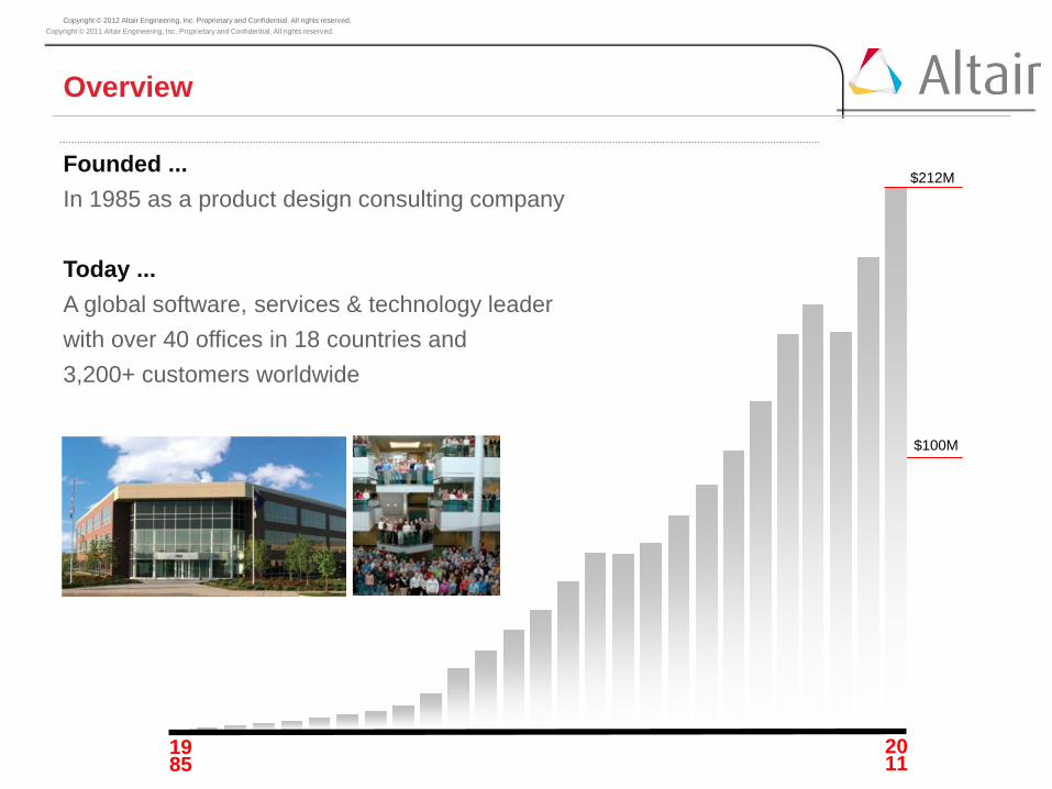
Overview
Founded ... In 1985 as a product design consulting company Today ... A global software, services & technology leader with over 40 offices in 18 countries and 3,200+ customers worldwide
19 85
20 11
$212M
$100M

Copyright © 2011 Altair Engineering, Inc. Proprietary and Confidential. All rights reserved.
1,500 Employees worldwide 500 Project engineers, designers and technicians 220 Software support engineers and application specialists
400 HyperWorks developers
TEAM
Substantial Technical Human Resources
Copyright © 2011 Altair Engineering, Inc. Proprietary and Confidential. All rights reserved.
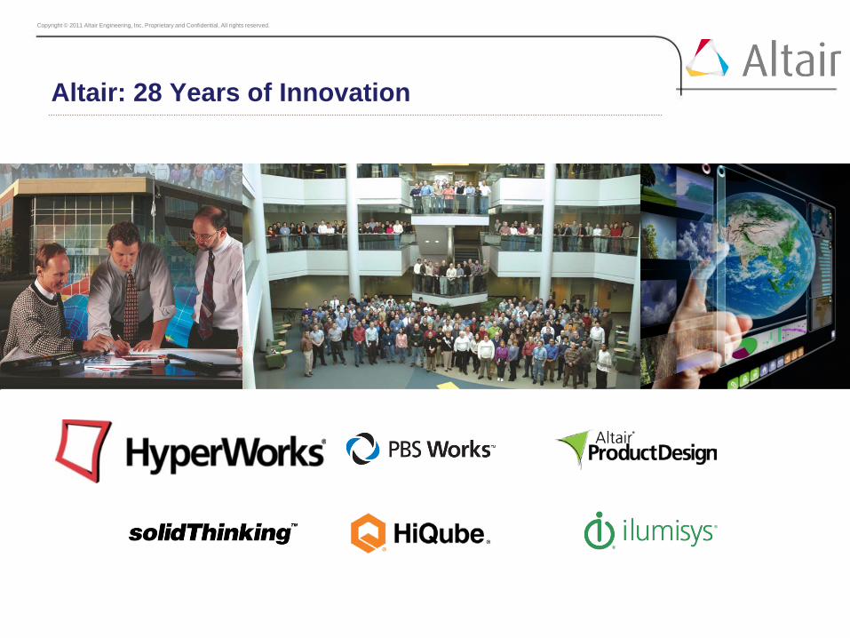
Altair: 28 Years of Innovation

Copyright © 2011 Altair Engineering, Inc. Proprietary and Confidential. All rights reserved.
HyperWorks for Academia
RADIOSS
Linear Non-Linear (Implicit)
Non-Linear (Explicit)
Thermal and CFD
Optimization – OptiStruct and HyperStudy
Multi-Body Dynamics
Partner Alliance Solutions
1-D Systems, Fatigue, Ergonomics, Industrial
Design, Injection Molding, Noise and Vbration (NVH),
Composite Materials, Electromagnetics
Pre-Post
RADIOSS - AcuSolve
RADIOSS - MotionSolve

Copyright © 2011 Altair Engineering, Inc. Proprietary and Confidential. All rights reserved. Copyright © 2012 Altair Engineering, Inc. Proprietary and Confidential. All rights reserved.
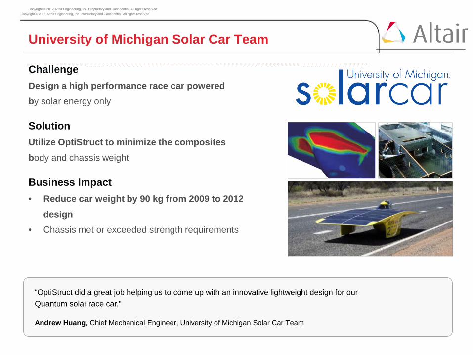
Challenge Design a high performance race car powered by solar energy only
Solution Utilize OptiStruct to minimize the composites body and chassis weight
Design Impact • Reduce car weight by 90 kg from 2009 to 2012
design • Chassis met or exceeded strength requirements
“OptiStruct did a great job helping us to come up with an innovative lightweight design for our Quantum solar race car.”
Andrew Huang, Chief Mechanical Engineer, University of Michigan Solar Car Team
University of Michigan Solar Car Team
Copyright © 2011 Altair Engineering, Inc. Proprietary and Confidential. All rights reserved. Copyright © 2012 Altair Engineering, Inc. Proprietary and Confidential. All rights reserved.
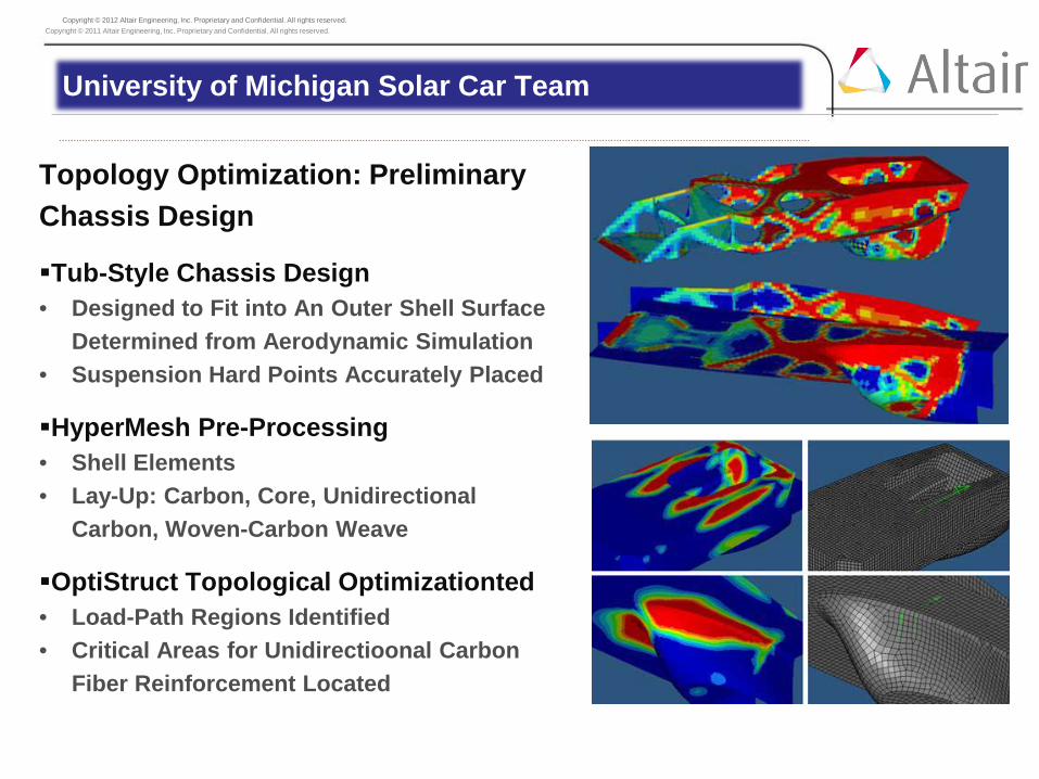
Topology Optimization: Preliminary Chassis Design
Tub-Style Chassis Design • Designed to Fit into An Outer Shell Surface
Determined from Aerodynamic Simulation • Suspension Hard Points Accurately Placed
HyperMesh Pre-Processing • Shell Elements • Lay-Up: Carbon, Core, Unidirectional
Carbon, Woven-Carbon Weave
OptiStruct Topological Optimizationted • Load-Path Regions Identified • Critical Areas for Unidirectioonal Carbon
Fiber Reinforcement Located
University of Michigan Solar Car Team

Copyright © 2011 Altair Engineering, Inc. Proprietary and Confidential. All rights reserved. Copyright © 2012 Altair Engineering, Inc. Proprietary and Confidential. All rights reserved.
Composite Size Optimization: Final Vehicle Design
Manufacturing Constraints • Imposed for Regions of Complex Carbon-
Layer Shape • Applied at High-Load Chassis Locations
(Suspension Hard Points)
HyperMesh Modeling • Shell Elements for Uni-Directional Carbon
Plies • 3D Hexahedral Elements for Core Material
Optimized Vehicle Weight Savings: 90 kg • 20 kg in Lower Unibody Chassis Design • 20 kg in Upper Vehicle Surface Design • 50 kg in Battery Design
University of Michigan Solar Car Team

Copyright © 2011 Altair Engineering, Inc. Proprietary and Confidential. All rights reserved. Copyright © 2012 Altair Engineering, Inc. Proprietary and Confidential. All rights reserved.
Coventry University Shell Eco-Marathon Team
Baseline Vehicle (2009) •Aluminum Tubular Chassis •Mass: 45 Kg •Poor Aero Performance
Composite Monocoque Concept (2010) •Feasibility Design •Aerodynamic Development Focus •Structural Development Needed
Fully Optimized Composite Monocoque (2011) •Fully Integrated Aero Design •Optimized Structure: 45 Kg •Designed for Manufacturability

Copyright © 2011 Altair Engineering, Inc. Proprietary and Confidential. All rights reserved. Copyright © 2012 Altair Engineering, Inc. Proprietary and Confidential. All rights reserved.
Coventry University Shell Eco-Marathon Team
Sandwich Structure Optimisation Process The reinforced sandwich structure approach started with the same 8 ply layup as pure carbon approach with the addition of 12mm honeycomb core in the floor and seatback sections.

Copyright © 2011 Altair Engineering, Inc. Proprietary and Confidential. All rights reserved. Copyright © 2012 Altair Engineering, Inc. Proprietary and Confidential. All rights reserved.
Coventry University Shell Eco-Marathon Team
Pure Carbon Optimisation Process The pure carbon fibre approach consisted of a complete covering of an 8 ply symmetrical layup. A three phase optimisation was utilized taking advantage of the automatic phase transitions.
Copyright © 2011 Altair Engineering, Inc. Proprietary and Confidential. All rights reserved. Copyright © 2012 Altair Engineering, Inc. Proprietary and Confidential. All rights reserved.
Coventry University Shell Eco-Marathon Team
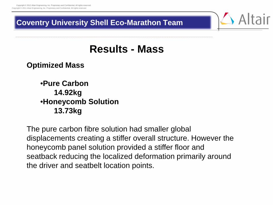
Results - Mass Optimized Mass
•Pure Carbon 14.92kg
•Honeycomb Solution 13.73kg
The pure carbon fibre solution had smaller global displacements creating a stiffer overall structure. However the honeycomb panel solution provided a stiffer floor and seatback reducing the localized deformation primarily around the driver and seatbelt location points.

Copyright © 2011 Altair Engineering, Inc. Proprietary and Confidential. All rights reserved. Copyright © 2012 Altair Engineering, Inc. Proprietary and Confidential. All rights reserved.
• OptiStruct is used within ME (Mechanical Engineering) and Segal Design Institute at Northwestern University:
• ME 341: Computational Methods for Engineering Design
• Senior undergraduate and entry level graduate
• ME 398: Engineering Design (Capstone Design) • Senior undergraduate
• ME 441: Engineering Optimization for Product Design and Manufacturing
• Entry level graduate • ME 495: Advanced Computational & Statistical
Methods for Engineering Design • Graduate level
Northwestern University Computational Design Courses

Copyright © 2011 Altair Engineering, Inc. Proprietary and Confidential. All rights reserved. Copyright © 2012 Altair Engineering, Inc. Proprietary and Confidential. All rights reserved.
ME 341: Computational Methods for Engineering Design • Altair HyperWorks Tutorials
• In-class tutorial for topology optimization
• Outside-class tutorial for size optimization
• Selected Students’ Class Projects
Northwestern University Computational Design Courses

Copyright © 2011 Altair Engineering, Inc. Proprietary and Confidential. All rights reserved. Copyright © 2012 Altair Engineering, Inc. Proprietary and Confidential. All rights reserved.
Northwestern University Computational Design Courses
ME 341 In-Class Tutorial for Topology Optimization
Copyright © 2011 Altair Engineering, Inc. Proprietary and Confidential. All rights reserved. Copyright © 2012 Altair Engineering, Inc. Proprietary and Confidential. All rights reserved.
Northwestern University Computational Design Courses
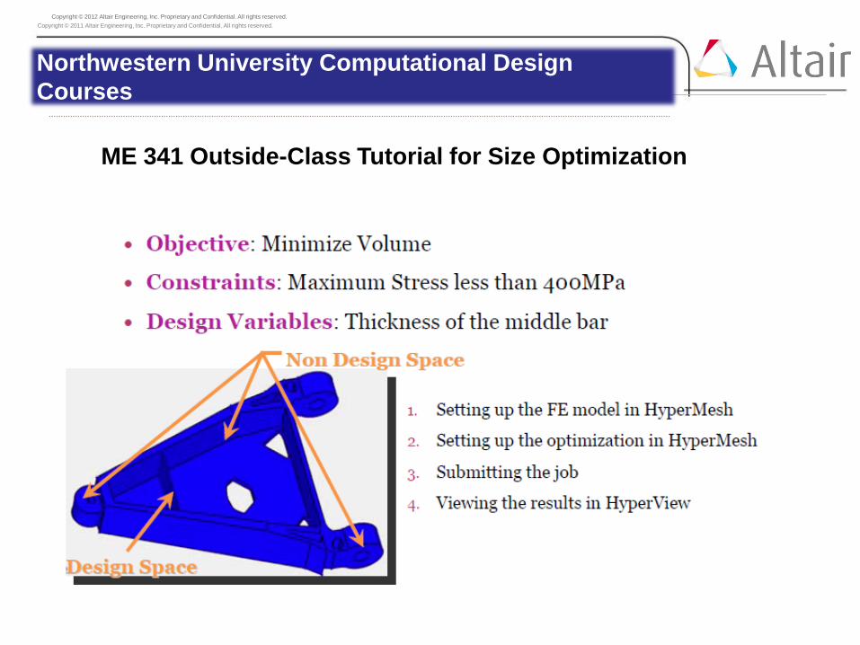
ME 341 Outside-Class Tutorial for Size Optimization
Copyright © 2011 Altair Engineering, Inc. Proprietary and Confidential. All rights reserved. Copyright © 2012 Altair Engineering, Inc. Proprietary and Confidential. All rights reserved.
Northwestern University Computational Design Courses
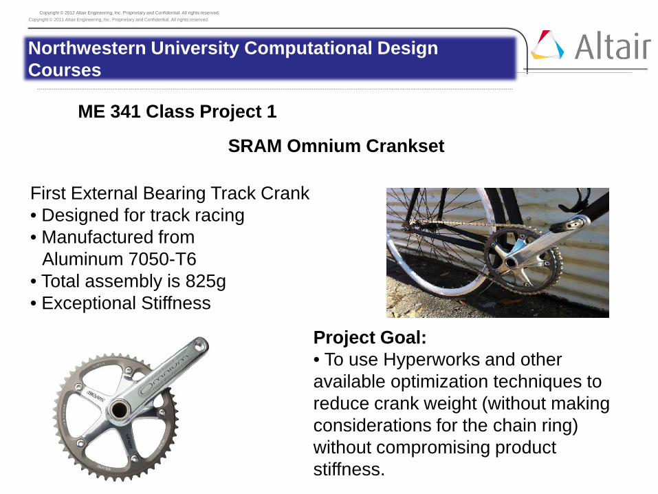
ME 341 Class Project 1
SRAM Omnium Crankset
First External Bearing Track Crank • Designed for track racing • Manufactured from
Aluminum 7050-T6 • Total assembly is 825g • Exceptional Stiffness
Project Goal: • To use Hyperworks and other available optimization techniques to reduce crank weight (without making considerations for the chain ring) without compromising product stiffness.

Copyright © 2011 Altair Engineering, Inc. Proprietary and Confidential. All rights reserved. Copyright © 2012 Altair Engineering, Inc. Proprietary and Confidential. All rights reserved.
Topology Optimization • Blank used to perform a topology optimization with respect to the
following constraints:
• Mass - Maximum 300g
• Compliance
- Minimization
• Materials - Steel - Aluminum -6061, 7075
Northwestern University Computational Design Courses
ME 341 Class Project 1

Copyright © 2011 Altair Engineering, Inc. Proprietary and Confidential. All rights reserved. Copyright © 2012 Altair Engineering, Inc. Proprietary and Confidential. All rights reserved.
Northwestern University Computational Design Courses
ME 341 Class Project 1
OptiStruct Contraints
Operation was performed with a 2000N load • Body allowed to rotate about spindle • Transverse movement of bolt holes prohibited

Copyright © 2011 Altair Engineering, Inc. Proprietary and Confidential. All rights reserved. Copyright © 2012 Altair Engineering, Inc. Proprietary and Confidential. All rights reserved.
Northwestern University Computational Design Courses
ME 341 Class Project 1 Topology Optimization Results- Aluminum 6061
Stresses: Displacement:

Copyright © 2011 Altair Engineering, Inc. Proprietary and Confidential. All rights reserved. Copyright © 2012 Altair Engineering, Inc. Proprietary and Confidential. All rights reserved.
Northwestern University Computational Design Courses
ME 341 Class Project 1
Results Summary
0 20 40 60 80
100 120
Aluminum 6061
Aluminum 7075
Steel
Perc
enta
ge
Material
Stresses
Percent of Yield
Percent of Ultimate
0 200 400 600 800
1000 1200 1400
Aluminum 6061 Aluminum 7075 Steel
Mas
s (g)
Material
Mass

Copyright © 2011 Altair Engineering, Inc. Proprietary and Confidential. All rights reserved. Copyright © 2012 Altair Engineering, Inc. Proprietary and Confidential. All rights reserved.
Northwestern University Computational Design Courses
ME 341 Class Project 2
Stamping Die Design Ford Motor Co. experiencing failure of a stamping die binder:
They have conducted a FE Analysis and created a new design, but they
would like to optimize the design:
Goal: Minimize the weight of the Binder. Subject to: Maximum Principle Stress is less than 40% binder material
yield stress.

Copyright © 2011 Altair Engineering, Inc. Proprietary and Confidential. All rights reserved. Copyright © 2012 Altair Engineering, Inc. Proprietary and Confidential. All rights reserved.
Northwestern University Computational Design Courses
ME 341 Class Project 2
Stamping Die Design Methodology: 2 Phase Analysis using HyperWorks:
Phase 1: Topology optimization Minimize compliance (max stiffness) subject to 25% maximum
volume fraction of material remaining. Phase 2: Size optimization
Minimize weight subject to a maximum principle stress level. Design Space created and loads and boundary conditions added:

Copyright © 2011 Altair Engineering, Inc. Proprietary and Confidential. All rights reserved. Copyright © 2012 Altair Engineering, Inc. Proprietary and Confidential. All rights reserved.
Northwestern University Computational Design Courses
ME 341 Class Project 2
Topology Optimization Results
• Results of the topology optimization with manufacturability constraints as shown:
Copyright © 2011 Altair Engineering, Inc. Proprietary and Confidential. All rights reserved. Copyright © 2012 Altair Engineering, Inc. Proprietary and Confidential. All rights reserved.
Northwestern University Computational Design Courses
ME 341 Class Project 2
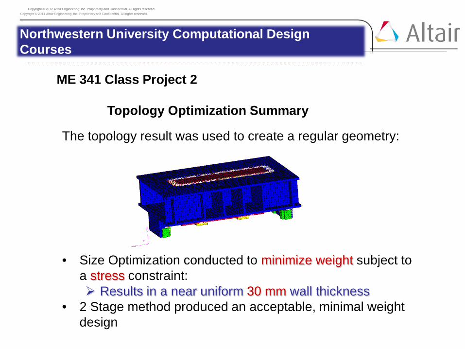
Topology Optimization Summary The topology result was used to create a regular geometry: • Size Optimization conducted to minimize weight subject to
a stress constraint: Results in a near uniform 30 mm wall thickness
• 2 Stage method produced an acceptable, minimal weight design

Copyright © 2011 Altair Engineering, Inc. Proprietary and Confidential. All rights reserved. Copyright © 2012 Altair Engineering, Inc. Proprietary and Confidential. All rights reserved.
Michigan Tech University: Board Sport Technologies Enterprise
Tutorial Development Related to Composite Wake Board Design
Three HyperWorks-Based Tutorials Were Completed: • Wakeboard Meshing Using HyperMesh
• Linear FE Analysis of the Wakeboard Subjected to Loads
Simulating the Rider Weight and Wakeboard Landing Resulting from Wave Jumping
• Wakeboard Optimization Using OptiStruct Shape Optimization Size Optimization Free-Size Optimization

Copyright © 2011 Altair Engineering, Inc. Proprietary and Confidential. All rights reserved. Copyright © 2012 Altair Engineering, Inc. Proprietary and Confidential. All rights reserved.
• Done behind a boat at 20-25 mph
• Specific boats for big wakes (and big impact)
Michigan Tech University: Board Sport Technologies Enterprise
Wakeboarding

Copyright © 2011 Altair Engineering, Inc. Proprietary and Confidential. All rights reserved. Copyright © 2012 Altair Engineering, Inc. Proprietary and Confidential. All rights reserved.
Wakeboard Geometry
Michigan Tech University: Board Sport Technologies Enterprise
Copyright © 2011 Altair Engineering, Inc. Proprietary and Confidential. All rights reserved. Copyright © 2012 Altair Engineering, Inc. Proprietary and Confidential. All rights reserved.
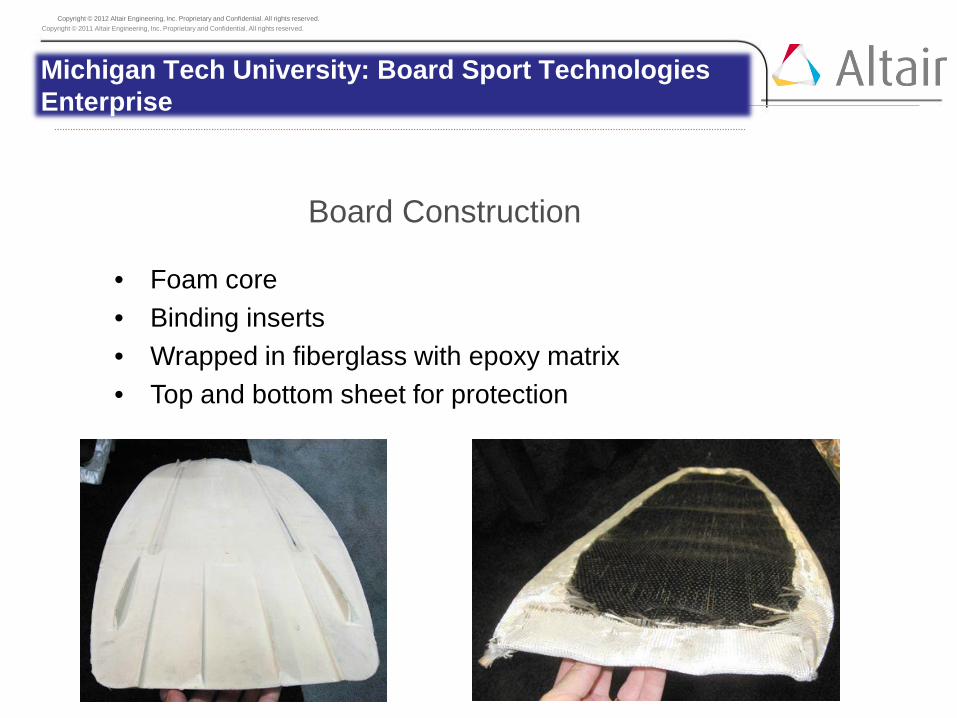
Board Construction
Michigan Tech University: Board Sport Technologies Enterprise
• Foam core • Binding inserts • Wrapped in fiberglass with epoxy matrix • Top and bottom sheet for protection

Copyright © 2011 Altair Engineering, Inc. Proprietary and Confidential. All rights reserved. Copyright © 2012 Altair Engineering, Inc. Proprietary and Confidential. All rights reserved.
Tutorial 1: Wakeboard Meshing Using HyperMesh
Michigan Tech University: Board Sport Technologies Enterprise
• Wakeboard Geometry Import
• Mesh ¼ of the Board
• Mesh Clean-Up & Reflection

Copyright © 2011 Altair Engineering, Inc. Proprietary and Confidential. All rights reserved. Copyright © 2012 Altair Engineering, Inc. Proprietary and Confidential. All rights reserved.
Tutorial 2: Linear FE Analysis of the Wakeboard Subjected to Loads Simulating the Rider Weight and Wakeboard Wave
Jumping
Michigan Tech University: Board Sport Technologies Enterprise
• Rider Loads (200 lb Person)
• Wave Impact Loads
• Results-Inertial Relief Analysis (Von Mises Stress-Board Bottom)
Copyright © 2011 Altair Engineering, Inc. Proprietary and Confidential. All rights reserved. Copyright © 2012 Altair Engineering, Inc. Proprietary and Confidential. All rights reserved.
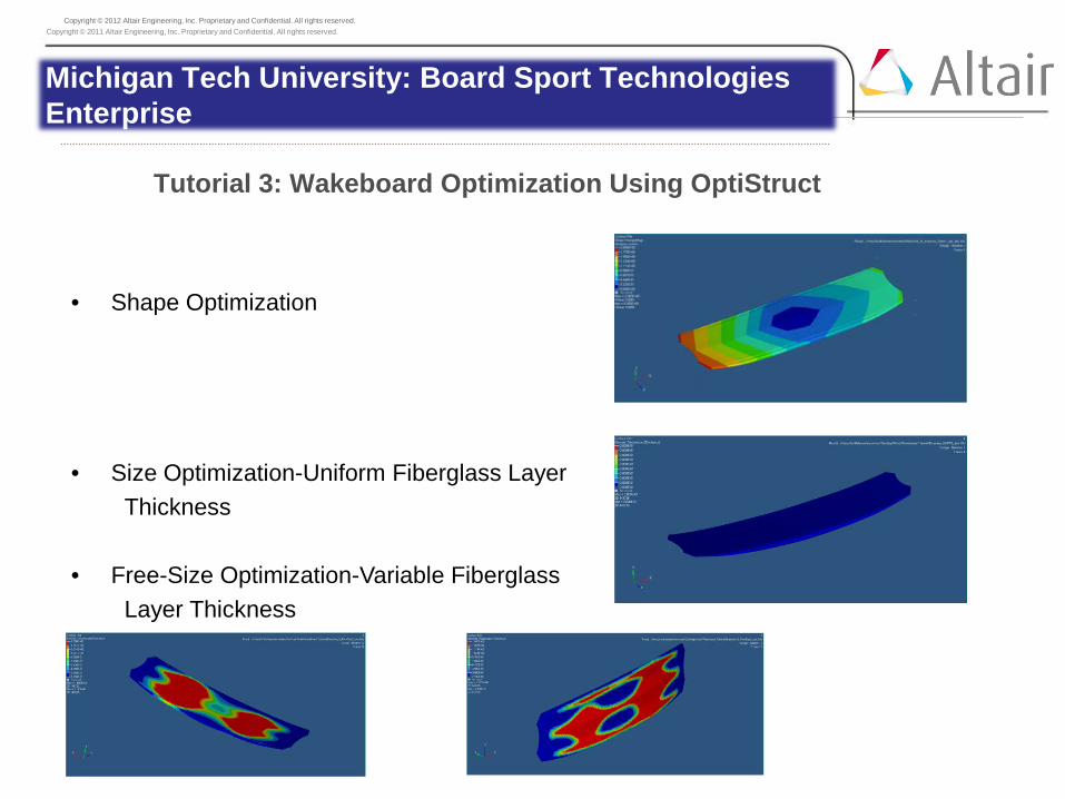
Tutorial 3: Wakeboard Optimization Using OptiStruct
Michigan Tech University: Board Sport Technologies Enterprise
• Shape Optimization
• Size Optimization-Uniform Fiberglass Layer Thickness
• Free-Size Optimization-Variable Fiberglass
Layer Thickness
Copyright © 2011 Altair Engineering, Inc. Proprietary and Confidential. All rights reserved.
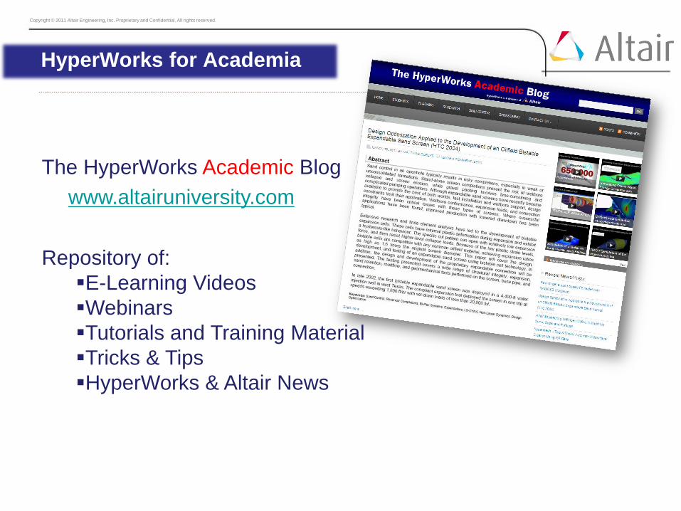
The HyperWorks Academic Blog www.altairuniversity.com
Repository of: E-Learning Videos Webinars Tutorials and Training Material Tricks & Tips HyperWorks & Altair News
HyperWorks for Academia

Copyright © 2011 Altair Engineering, Inc. Proprietary and Confidential. All rights reserved.
The HyperWorks Starter Kit
www.altairuniversity.com/..... Download Path
A very basic introduction for HyperMesh beginners Summary of hints and recommendations Ideally to be read before the first HyperMesh class starts
HyperWorks for Academia
Copyright © 2011 Altair Engineering, Inc. Proprietary and Confidential. All rights reserved. Copyright © 2012 Altair Engineering, Inc. Proprietary and Confidential. All rights reserved.
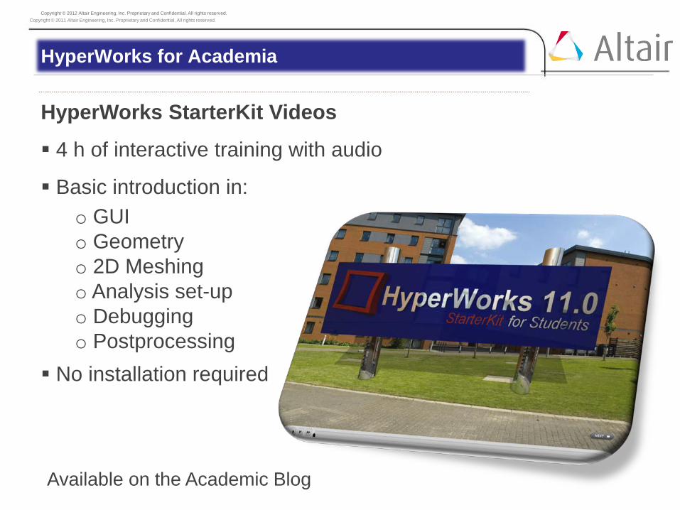
HyperWorks StarterKit Videos
4 h of interactive training with audio
Basic introduction in: o GUI o Geometry o 2D Meshing o Analysis set-up o Debugging o Postprocessing
No installation required
Available on the Academic Blog
HyperWorks for Academia

Copyright © 2011 Altair Engineering, Inc. Proprietary and Confidential. All rights reserved.
Capabilities •Desktop Framework
•HyperMesh •HyperView •HyperGraph •OptiStruct •Radioss bulk (b2b) •Collaboration Tools
•HyperView Player
HyperWorks 11.0 Student Edition

Copyright © 2011 Altair Engineering, Inc. Proprietary and Confidential. All rights reserved.
Limitations
•10,000 nodes
Models in HM can be larger (but not exported/saved)
Limitation applies during import *.h3d in HV/HG
•CAD formats: IGES, STEP, SolidWorks
•Import of HM, OS and Radioss bulk only
•Analysis and optimization may only be started within HM
•Platforms: Windows 32 (XP, Vista, 7)
•Database IS compatible with regular version
•May NOT be used for commercial purposes
HyperWorks 11.0 Student Edition

Copyright © 2011 Altair Engineering, Inc. Proprietary and Confidential. All rights reserved. Copyright © 2012 Altair Engineering, Inc. Proprietary and Confidential. All rights reserved.
Free E-Book (2nd Edition) What is needed to run a FEA Strategic Planning Common Mistakes and Errors Consistent Units Geometry 1D-2D-3D Meshing Static Analysis NL Implicit Analysis Postprocessing
Available on the Academic Blog
HyperWorks for Academia

Copyright © 2011 Altair Engineering, Inc. Proprietary and Confidential. All rights reserved. Copyright © 2012 Altair Engineering, Inc. Proprietary and Confidential. All rights reserved.
Let us know your ideas and requests.
Thank You!
HyperWorks for Academia

Copyright © 2011 Altair Engineering, Inc. Proprietary and Confidential. All rights reserved.
HyperWorks Simulation Technolgy
OptiStruct Optimization

Copyright © 2011 Altair Engineering, Inc. Proprietary and Confidential. All rights reserved. Copyright © 2012 Altair Engineering, Inc. Proprietary and Confidential. All rights reserved.
Altair Optimization Driven Innovation
Your professor asks you the follwing:
„For the given stucture I need to have a new,
more innovative, and lighter solution.
Delivery date: Yesterday …“
What is your Strategy?

Copyright © 2011 Altair Engineering, Inc. Proprietary and Confidential. All rights reserved. Copyright © 2012 Altair Engineering, Inc. Proprietary and Confidential. All rights reserved.
What if there are no similar or previous designs to reference?
What if the similar design doesn’t scale for the new configuration?
What if you don’t have experience with this type of design?
What if previous designs were never optimized for weight?
What if you have many load cases?
What if you have limited time to make design changes?
What if your engineering judgment leads you down the wrong path?
…
Challenges of the early design phase
Altair Optimization Driven Innovation

Copyright © 2011 Altair Engineering, Inc. Proprietary and Confidential. All rights reserved. Copyright © 2012 Altair Engineering, Inc. Proprietary and Confidential. All rights reserved.
Altair Optimization Driven Innovation
... Innovative or „old“ and well known
solutions ???
In the concept phase the designer has maximum design freedom, but minimum design knowledge
Challenges of the early design phase – in a nutshell
80% of the product weight is determined at the concept design stage
Copyright © 2011 Altair Engineering, Inc. Proprietary and Confidential. All rights reserved. Copyright © 2012 Altair Engineering, Inc. Proprietary and Confidential. All rights reserved.
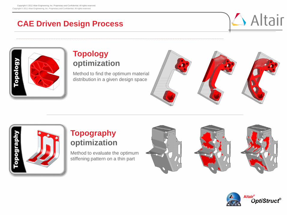
CAE Driven Design Process
Topology optimization Method to find the optimum material distribution in a given design space
Topography optimization Method to evaluate the optimum stiffening pattern on a thin part

Copyright © 2011 Altair Engineering, Inc. Proprietary and Confidential. All rights reserved. Copyright © 2012 Altair Engineering, Inc. Proprietary and Confidential. All rights reserved.
Size optimization Method to obtain optimum
dimensions of structural parts
Shape optimization
Find optimum shape of given part
CAE Driven Design Process

Copyright © 2011 Altair Engineering, Inc. Proprietary and Confidential. All rights reserved. Copyright © 2012 Altair Engineering, Inc. Proprietary and Confidential. All rights reserved.
Bus Body Structure
• Method’s Used: • Design package space created based on overall bus dimensions and sub-system
packaging constraints. Loads Determined analytically
• OptiStruct topology optimization used to create the initial concept design
• Concept Design interpreted to render it manufacturable
• OptiStruct Shape/Size optimization used for tuning the concept design
• Design Problem • Develop an alternative body structure for a new
30’ bus (compared to a conventional 40’ bus) from concept through detail
• Optimization Problem statement: • Minimize “Weight” • With Constraints on
• Torsional and Bending frequencies • Stiffness (Static Displacements) Final Design
Altair Optimization Driven Innovation

Copyright © 2011 Altair Engineering, Inc. Proprietary and Confidential. All rights reserved. Copyright © 2012 Altair Engineering, Inc. Proprietary and Confidential. All rights reserved.
CAD model with generic elements
Parametric Shape Vectors
Finite Element Modeling
Design Space and
Loads
Size and Shape Optimization
Topology Optimization
Final Design
Altair Optimization Driven Innovation
System Level Requirements (loads analysis & packaging)

Copyright © 2011 Altair Engineering, Inc. Proprietary and Confidential. All rights reserved. Copyright © 2012 Altair Engineering, Inc. Proprietary and Confidential. All rights reserved.
Altair Bus
December 2010
June 2010
Altair Optimization Driven Innovation

Copyright © 2011 Altair Engineering, Inc. Proprietary and Confidential. All rights reserved. Copyright © 2012 Altair Engineering, Inc. Proprietary and Confidential. All rights reserved.
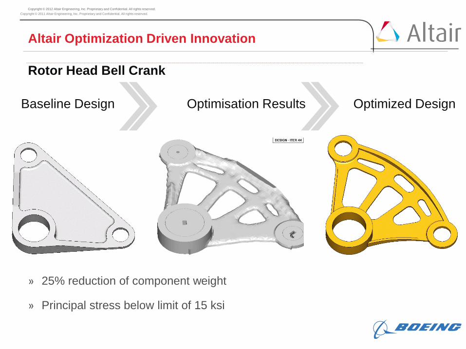
Rotor Head Bell Crank
Altair Optimization Driven Innovation

Copyright © 2011 Altair Engineering, Inc. Proprietary and Confidential. All rights reserved. Copyright © 2012 Altair Engineering, Inc. Proprietary and Confidential. All rights reserved.
Design Problem » 6 Load Cases » Machined from one direction » Maintain pad-ups around attach points to interface
with existing structure » Reduce mass 10% while keeping stress limit on
previously optimized design
Optimisation Statement » Minimise Mass » Constraint on Stress (15ksi)
Methodology » Topology optimisation with Draw Direction
manufacturing constraints » Shape optimization to determine wall thickness'
Rotor Head Bell Crank
Altair Optimization Driven Innovation

Copyright © 2011 Altair Engineering, Inc. Proprietary and Confidential. All rights reserved. Copyright © 2012 Altair Engineering, Inc. Proprietary and Confidential. All rights reserved.
Solid model meshed with Hex elements.
» Design region specified (green)
» Non-Design region (blue) separated
Rotor Head Bell Crank
Altair Optimization Driven Innovation
Copyright © 2011 Altair Engineering, Inc. Proprietary and Confidential. All rights reserved. Copyright © 2012 Altair Engineering, Inc. Proprietary and Confidential. All rights reserved.
» 25% reduction of component weight
» Principal stress below limit of 15 ksi
Optimisation Results Optimized Design Baseline Design
Rotor Head Bell Crank
Altair Optimization Driven Innovation

Copyright © 2011 Altair Engineering, Inc. Proprietary and Confidential. All rights reserved.
HyperWorks Simulation Technolgy
Composites Design Optimization
Copyright © 2011 Altair Engineering, Inc. Proprietary and Confidential. All rights reserved.
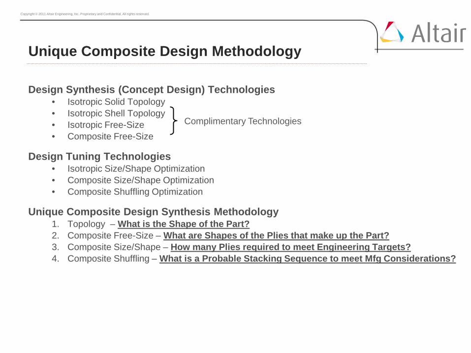
Unique Composite Design Methodology
Design Synthesis (Concept Design) Technologies • Isotropic Solid Topology • Isotropic Shell Topology • Isotropic Free-Size • Composite Free-Size
Design Tuning Technologies • Isotropic Size/Shape Optimization • Composite Size/Shape Optimization • Composite Shuffling Optimization
Unique Composite Design Synthesis Methodology 1. Topology – What is the Shape of the Part? 2. Composite Free-Size – What are Shapes of the Plies that make up the Part? 3. Composite Size/Shape – How many Plies required to meet Engineering Targets? 4. Composite Shuffling – What is a Probable Stacking Sequence to meet Mfg Considerations?
Complimentary Technologies

Copyright © 2011 Altair Engineering, Inc. Proprietary and Confidential. All rights reserved.
Composite Free-Size Optimization
Isotropic Free-Size vs. Composite Free-Size
Captures Coupling Between Total Thickness and Ratio of Ply Orientations (%0 %45 %90) by Updating Individual Ply Thickness
Stacking Sequence Effects Captured by SMEAR Technology • A = Stacking Sequence Independent • B = 0 • D = At2/12 – Stacking Sequence Independent
Unique Composite Design Synthesis – “Growing of Plies”
T = Lower T = Upper PSHELL
T = Ply3 (opti) 90
T = Ply2 (opti) -45 T = Ply4 (nom) 45
PCOMP
sym
T = Lower T = Upper
T = Ply3 (nom) 90
T = Ply2 (nom) -45
T = Ply1 (nom) 0
T = Ply4 (opti) 45
PCOMP
sym
T = Ply1 (opti) 0 T_0
T_Total
After Optimization
Continuous Thickness between T_Lower and T_Upper
Copyright © 2011 Altair Engineering, Inc. Proprietary and Confidential. All rights reserved.
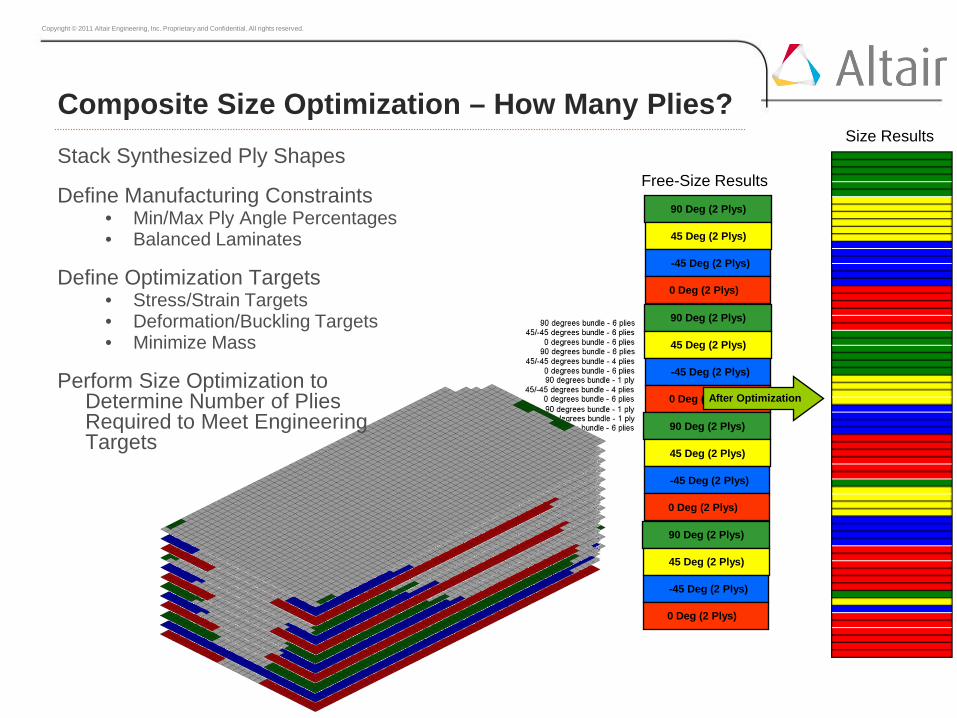
Composite Size Optimization – How Many Plies? Stack Synthesized Ply Shapes
Define Manufacturing Constraints • Min/Max Ply Angle Percentages • Balanced Laminates
Define Optimization Targets • Stress/Strain Targets • Deformation/Buckling Targets • Minimize Mass
Perform Size Optimization to Determine Number of Plies Required to Meet Engineering Targets
90 Deg (2 Plys)
45 Deg (2 Plys)
-45 Deg (2 Plys)
0 Deg (2 Plys)
90 Deg (2 Plys)
45 Deg (2 Plys)
-45 Deg (2 Plys)
0 Deg (2 Plys)
90 Deg (2 Plys)
45 Deg (2 Plys)
-45 Deg (2 Plys)
0 Deg (2 Plys)
After Optimization
90 Deg (2 Plys)
45 Deg (2 Plys)
-45 Deg (2 Plys)
0 Deg (2 Plys)
Free-Size Results
Size Results

Copyright © 2011 Altair Engineering, Inc. Proprietary and Confidential. All rights reserved.
Composite Shuffling – What is a Probable Stacking?
Shuffling • Defines “Probable” Stacking Sequence • Obeys Manufacturing Constraints
Manufacturing Constraints • Min/Max Total Laminate Thickness • Min/Max Ply Thickness • Min/Max Ply Angle Percentage • Balanced Ply Angles • Constant Ply Thickness
After Optimization
Size Results Shuffle Results
Copyright © 2011 Altair Engineering, Inc. Proprietary and Confidential. All rights reserved. Copyright © 2012 Altair Engineering, Inc. Proprietary and Confidential. All rights reserved.
University of Michigan Solar Car Team
Challenge Design a high performance race car powered by solar energy only
Solution Utilize OptiStruct to minimize the composites body and chassis weight
Business Impact • Reduce car weight by 90 kg from 2009 to 2012
design • Chassis met or exceeded strength requirements
“OptiStruct did a great job helping us to come up with an innovative lightweight design for our Quantum solar race car.”
Andrew Huang, Chief Mechanical Engineer, University of Michigan Solar Car Team

Copyright © 2011 Altair Engineering, Inc. Proprietary and Confidential. All rights reserved.
Goal: • Determine the laminate lay-up & composite patch
positions
Optimization Objective: • Minimize the Mass
Subject to: • Multiple target wing displacement fields • (Twisting – Bending)
Solution using Free Element Sizing optimization: • Determine whether displacement fields are achievable • Determine minimum required mass
Due to the complexity of the structure and the number of load cases, without this technology, a ‘trial and error’ process would not be commercially realistic.
• Note: • The 45 & -45 layer thicknesses are
linked (new OptiStruct feature) • Only symmetric laminates are
considered for all studies. • Use smearing option to simulate
uniformly distributed ply stack.
Marc Funnell (Airbus UK) Altair Paper: Targeting Composite Wing Performance – Optimum Location of Laminate Boundaries
Case Study

Copyright © 2011 Altair Engineering, Inc. Proprietary and Confidential. All rights reserved. Pl
y An
gle
= 0
Bending Only Twist and Bending: 9.6% increase in mass
Ply
Angl
e =
90
Ply
Angl
e =
45/-4
5
-5.6%
Change in mass
134.7%
Change in mass
17.3%
Change in mass
Free Size Optimization (FSO) - Results

Copyright © 2011 Altair Engineering, Inc. Proprietary and Confidential. All rights reserved.
The optimization took approx 6 minutes on a laptop & converged in about 10 iterations
The optimization quickly & easily shows: • Plies can be tailored to meet specific displacement & twist angle targets • Where patches of each orientation are required • Optimized Mass prediction • Ply lay-up has a direct effect upon the bending & torsional stiffness • Patch positions are dependent upon loading AND design constraints
Free Size Optimization (FSO) - Summary
Total thickness contour Bending Target Only
Total thickness contour Twist & Bending Target

Copyright © 2011 Altair Engineering, Inc. Proprietary and Confidential. All rights reserved.
HyperWorks Simulation Technolgy
HyperStudy Multi-Physics Analysis

Copyright © 2011 Altair Engineering, Inc. Proprietary and Confidential. All rights reserved. Copyright © 2012 Altair Engineering, Inc. Proprietary and Confidential. All rights reserved.
HyperWorks for Academia – Optimization
HyperStudy - Solver Neutral Design of Experiment, Multi-Disciplinary
Optimization and Stochastic Simulation Engine
•Automates processes for parametric study, optimization and robustness assessment
• Integrated with HyperWorks thru HyperMesh, MotionView and direct solver interfaces
Copyright © 2011 Altair Engineering, Inc. Proprietary and Confidential. All rights reserved.
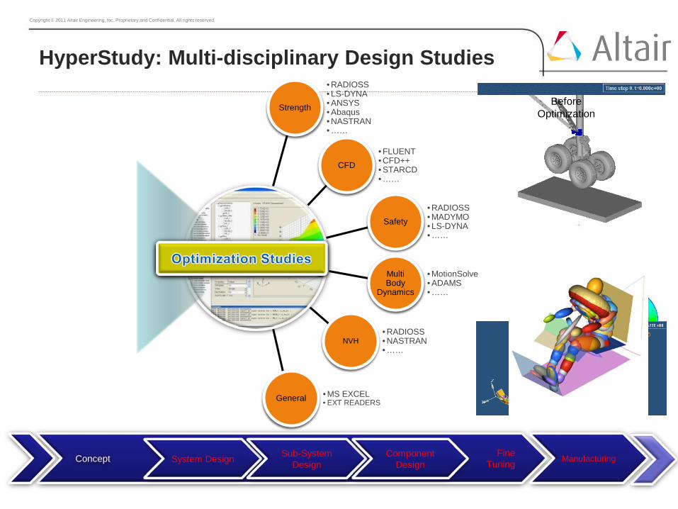
HyperStudy: Multi-disciplinary Design Studies
CFD
Safety
Multi Body
Dynamics
NVH
General
• RADIOSS • LS-DYNA • ANSYS • Abaqus • NASTRAN • ……
• RADIOSS • MADYMO • LS-DYNA • ……
• MotionSolve • ADAMS • ……
• RADIOSS • NASTRAN • ……
• MS EXCEL • EXT READERS
• FLUENT • CFD++ • STARCD • ……
Strength
CFD
Safety
Multi Body
Dynamics
NVH
General
Strength Before Optimization
After Optimization
Fine Tuning System Design Sub-System
Design Component
Design Manufacturing Concept

Copyright © 2011 Altair Engineering, Inc. Proprietary and Confidential. All rights reserved. Copyright © 2012 Altair Engineering, Inc. Proprietary and Confidential. All rights reserved.
Astrium Aurora Mars Module
Challenge Layout airbag landing system of Aurora Mars Lander
Ensure safe and reliable landing
Virtual process: only limited testing possible
Solution HyperStudy to optimize airbag parameter to ensure soft
landing
Minimize risk of landing failure through Monte Carlo
study
Results 93% less payload acceleration in “dive through” landing
scenario
44% reduction in airbag stresses

Copyright © 2011 Altair Engineering, Inc. Proprietary and Confidential. All rights reserved.
Case Study CAE Driven Design of Airbag Systems at TAKATA
“By applying HyperStudy’s automatic shape optimization to the airbag design process, we were able to cut development time dramatically, with transparent and objective results.”
Axel Heym CAE Manager, TAKATA-PETRI AG, Germany
Challenge • Geometric layout of the airbag required numerous CAD-CAE iterations • Needed to reduce development time
Solution
• Upfront optimization using HyperWorks’ morphing technology • Morphing to parameterize the airbag without CAD data
Results
• Automatic process: no expertise in airbag design needed • Elimination of CAD-CAE iterations • Over 30% reduction in development time
Before:
After Optimization:


