

Institutionen för datavetenskap Department of Computer and Information Science
Final thesis
Software Process Improvement and
Lifecycle Models in Automotive Industry
by
Suneel Sabar
LIU-IDA /LITH-EX-A—11/022—SE
2011-06-09
Linköpings universitet
581 83 Linköping
Linköpings universitet
SE-581 83 Linköping, Sweden


Final Thesis
Software Process Improvement and
Lifecycle Models in Automotive Industry
by
Suneel Sabar
LIU-IDA /LITH-EX-A—11/022—SE
2011-06-09
Supervisor: Bengt-Arne Nyman
Examiner: Kristian Sandahl
Institutionen för datavetenskap
Linköpings universitet
581 83 Linköping
Linköping University
Department of Computer and Information Science

På svenska Detta dokument hålls tillgängligt på Internet – eller dess framtida ersättare – under en
längre tid från publiceringsdatum under förutsättning att inga extra-ordinära
omständigheter uppstår.
Tillgång till dokumentet innebär tillstånd för var och en att läsa, ladda ner, skriva ut enstaka
kopior för enskilt bruk och att använda det oförändrat för ickekommersiell forskning och för
undervisning. Överföring av upphovsrätten vid en senare tidpunkt kan inte upphäva detta
tillstånd. All annan användning av dokumentet kräver upphovsmannens medgivande. För att
garantera äktheten, säkerheten och tillgängligheten finns det lösningar av teknisk och
administrativ art.
Upphovsmannens ideella rätt innefattar rätt att bli nämnd som upphovsman i den
omfattning som god sed kräver vid användning av dokumentet på ovan beskrivna sätt samt
skydd mot att dokumentet ändras eller presenteras i sådan form eller i sådant sammanhang
som är kränkande för upphovsmannens litterära eller konstnärliga anseende eller egenart.
För ytterligare information om Linköping University Electronic Press se förlagets hemsida
http://www.ep.liu.se/
In English
The publishers will keep this document online on the Internet - or its possible replacement -
for a considerable time from the date of publication barring exceptional circumstances.
The online availability of the document implies a permanent permission for anyone to read,
to download, to print out single copies for your own use and to use it unchanged for any
non-commercial research and educational purpose. Subsequent transfers of copyright can’t
revoke this permission. All other uses of the document are conditional on the consent of the
copyright owner. The publisher has taken technical and administrative measures to assure
authenticity, security and accessibility.
According to intellectual property law the author has the right to be mentioned when
his/her work is accessed as described above and to be protected against infringement.
For additional information about the Linköping University Electronic Press and its procedures
for publication and for assurance of document integrity, please refer to its WWW home
page: http://www.ep.liu.se/
© Suneel Sabar
v
Acknowledgements
I would like to express my deep and sincere gratitude to my
supervisor Bengt-Arne Nyman, who provided me with this opportunity
to work under his supervision. His guidance, encouragement,
motivation and constructive criticism helped me to learn and improve
a lot throughout this thesis.
I would thank those two software team leaders and their teams as
well whom I observed and interviewed. I would also like to thank my
university supervisor, Prof. Kristian Sandahl, Linköping University
(LiU), for his support and guidance throughout this master’s degree.
Finally, my loving thanks are due to my family for their
encouragement, support and prayers throughout my studies.

vi

vii
Abstract
The quality of a product depends on the quality of the underlying process is a well known
fact. Software development organizations have been struggling to decrease their cost,
increase their ROI, reduce time-to-market, and enhance the quality of their products. This all
depends upon the improvement in the processes they are following inside their
organizations. A number of software process improvement models exist in market, e.g.,
CMMI, SPICE and Automotive SPICE. But before an organization can improve its development
and management processes, it is very important to know whether it is following the right
processes. There exist a number of software development process models, mainly
categorized into Traditional and Agile, which provide the step-by-step guidance to develop
and manage the software projects.
The current thesis presents a study of software process improvement models in automotive
industry, their weaknesses and strengths and presents a comparison of how do they relate to
each other. This thesis also explores some software development models which are more
famous in automotive industry, and the applicability of process improvement models in
conjunction with the Agile software development models. A case study was performed at an
automotive software supplier organization to investigate the experience of combining Agile
practices with organization’s company-tailored software development model that was
incorporating Automotive SPICE standards.
Keywords: SPI, CMMI, ISO/IEC 15540, SPICE, Automotive SPICE, SDLC, Incremental
Development, Agile, Scrum, Lean, Iteration Scope.

viii

ix
Table of Contents
Chapter 1 – Introduction ................................................................................................................... 1
1.1 – Background ..................................................................................................................................... 1
1.2 – Purpose ........................................................................................................................................... 2
1.3 – Research Questions ........................................................................................................................ 3
1.4 – Motivation ...................................................................................................................................... 3
1.5 – Research Method ........................................................................................................................... 4
1.6 – Report Structure ............................................................................................................................. 5
1.7 – Intended Readers ........................................................................................................................... 6
1.8 – Limitations ...................................................................................................................................... 6
Chapter 2 – CMMI ............................................................................................................................. 7
2.1 – Overview ......................................................................................................................................... 7
2.1.1 – From CMM to CMMI ............................................................................................................... 7
2.1.2 – CMMI Constellations ............................................................................................................... 8
2.1.3 – CMMI Appraisals ..................................................................................................................... 9
2.2 – CMMI for Development (CMMI-DEV) ............................................................................................ 9
2.3 – The Overall Structure ..................................................................................................................... 9
2.3.1 – Process Area Components ..................................................................................................... 10
2.3.2 – Process Area Categories ........................................................................................................ 12
2.3.3 – One Model – Two Representations ....................................................................................... 13
2.4 – Capability Levels ........................................................................................................................... 15
2.5 – Maturity Levels ............................................................................................................................. 16
2.6 – Maturity Levels and Process Areas ............................................................................................... 18
2.7 – Equivalent Staging ........................................................................................................................ 20
2.8 – Summary and Concluding Remarks .............................................................................................. 20
Chapter 3 – ISO/IEC 15504 – SPICE ................................................................................................... 22
3.1 – Overview ....................................................................................................................................... 22
3.1.1 – Uses of ISO/IEC 15504 ........................................................................................................... 22
3.1.2 – ISO/IEC 15504 – Parts ............................................................................................................ 23
3.2 – SPICE Structure ............................................................................................................................. 24
3.2.1 – Process Dimension ................................................................................................................ 26
3.2.2 – Capability Dimension ............................................................................................................. 27
3.3 – Industry based SPICE Models ....................................................................................................... 29

x
3.4 – Summary and Concluding Remarks .............................................................................................. 30
Chapter 4 – Automotive SPICE (A-SPICE) ......................................................................................... 33
4.1 – Overview ....................................................................................................................................... 33
4.1.1 – Automotive SPICE Objectives ................................................................................................ 33
4.2 – Automotive SPICE PRM ................................................................................................................ 34
4.3 – Automotive SPICE PAM ................................................................................................................ 34
4.3.1 – A.SPICE Process Dimension ................................................................................................... 34
4.3.2 – A.SPICE Capability Dimension ................................................................................................ 36
4.3.3 – Rating Scale Calibration ......................................................................................................... 37
4.4 – HIS Scope – Selected Processes .................................................................................................... 39
4.5 – Assessment Indicators .................................................................................................................. 40
4.5.1 – Process Capability Indicators ................................................................................................. 41
4.5.2 – Process Performance Indicators ............................................................................................ 41
4.6 – Recording Assessment Results ..................................................................................................... 42
4.7 – Summary and Concluding Remarks .............................................................................................. 45
Chapter 5 – Comparison & Mapping ................................................................................................ 46
5.1 – Structural Comparison .................................................................................................................. 46
5.1.1 – Representation Models ......................................................................................................... 47
5.1.2 – Quantitative Values ............................................................................................................... 47
5.1.3 – Terminologies ........................................................................................................................ 48
5.2 – Contents Comparison ................................................................................................................... 49
5.2.1 – Scope ..................................................................................................................................... 49
5.2.2 – Categories / Groups ............................................................................................................... 49
5.2.3 – Process Areas / Processes ..................................................................................................... 50
5.2.4 – Process Mapping ................................................................................................................... 52
5.2.5 – CMMI Maturity Levels Processes .......................................................................................... 54
5.3 – Summary and Concluding Remarks .............................................................................................. 57
Chapter 6 – Software Development Life Cycle (SDLC) Models ........................................................... 59
6.1 – Background and Overview ........................................................................................................... 59
6.2 – Traditional SDLC Models............................................................................................................... 61
6.2.1 – Waterfall Model .................................................................................................................... 61
6.2.2 – Incremental Model ................................................................................................................ 64
6.2.3 – V – Model .............................................................................................................................. 66
6.2.4 – Rational Unified Process (RUP) Model .................................................................................. 68

xi
6.3 – Agile Methods............................................................................................................................... 71
6.3.1 – Extreme Programming (XP) ................................................................................................... 73
6.3.2 – SCRUM ................................................................................................................................... 76
6.3.3 – Lean Software Development ................................................................................................. 81
6.4 – Agile and SPICE ............................................................................................................................. 86
6.5 – Summary and Comparison ........................................................................................................... 89
Chapter 7 – Lifecycle Model at AE .................................................................................................... 91
7.1 – Development at AE ....................................................................................................................... 91
7.1.1 – Product Development Process Model ................................................................................... 91
7.1.2 – Project Teams Structure ........................................................................................................ 93
7.1.3 – Software Development Model .............................................................................................. 93
7.1.4 – Team Management ............................................................................................................... 96
7.2 – Interviews and Observations ........................................................................................................ 97
7.2.1 – Project–A Team ..................................................................................................................... 97
7.2.2 – Project-B Team ...................................................................................................................... 98
7.3 – Discussion ................................................................................................................................... 100
7.3.1 – Project A .............................................................................................................................. 100
7.3.2 – Project B .............................................................................................................................. 102
7.3.3 – Comparison ......................................................................................................................... 103
7.4 – Concluding Remarks ................................................................................................................... 104
Chapter 8 – Conclusions ................................................................................................................. 106
Annex – A ...................................................................................................................................... 110
CMMI-DEV Generic Goals and Generic Practices ................................................................................ 110
Annex – B ...................................................................................................................................... 111
Automotive SPICE Process Attributes and Generic Practices ............................................................. 111
Annex – C ...................................................................................................................................... 113
System Diagram [19] ........................................................................................................................... 113
Annex – D ...................................................................................................................................... 114
Interview Questions ............................................................................................................................ 114
References ..................................................................................................................................... 115
Acronyms and Abbreviations .......................................................................................................... 119

xii

1
Chapter 1 – Introduction
1.1 – Background In the current age of science and technology, Software has gained the status of an essential
component in our daily lives because of our ever increasing dependability on the machines
having embedded software that control their functionality, e.g., electronic equipments. But
the development of such software is not a simple task; it includes a number of complexities.
Software development industry has been facing a number of issues in this business, such as:
it is an expensive business with a lot of initial investment, time and budget overruns,
schedule delays, project cancellations, and last but not least the quality of the delivered
software product. Furthermore, most of the software are completed with problems in them
which are then resolved after delivering the software. This leads to unhappy customers and
a poor quality of the products.
The quality of a product depends on the quality of the underlying process is a well known
fact. Nowadays, one of the major concerns of the software development organizations is the
improvement in quality, not only in their final software products, but also in the services
they provide, and most importantly in the management of their development processes.
Another concept which is becoming extremely famous in today’s globalized economy is to
include products and services developed by a network of in-house development, external
manufacturers, suppliers, and equal partners. The key attractions behind this trend are the
low-cost locations and involvement in strategic partnerships. But this broader interaction
raises questions about the managements of this complex co-operation and value chain, and
the assurance about adhering to the cost and schedule, and desired quality. The answer, to
these questions and earlier stated problems, is the way in which the processes of
management, engineering, quality assurance, acquisition, and cooperation with external
partners are implemented and controlled [1].
This improvement in quality has now become too important and necessary for staying on
top of the ever growing software development industry with a large number of competitors,
and ever demanding customers. To improve the processes, first of all, an organization has to
consider whether it is following the “right” processes. If so, then assess what are the
weaknesses and problems in those processes; what are the things which need
improvements; and how to improve them.
A number of software development methodologies have been introduced in past years to
guide and manage the development processes of software. These methodologies are usually
called Software Development Life Cycle (SDLC) models. These methodologies are divided
into two main groups, Traditional and Agile. Each organization is following one or more of
these methods, a hybrid of two or more, or a company-tailored model depending upon the
2
project needs and organization’s business goals. These processes may always not be the
perfect ones and need improvements.
A lot of research has been done, previously, to come up with Software Process Improvement
(SPI) models. The main purposes of such models are to improve efficiency, to reduce cost, to
lessen time-to-market, and to increase quality and reliability levels of the software. These
models incorporate “best practices” from software engineering industry which have been
successfully used to solve the above stated issues. These models are now widely
acknowledged and considered as a way of assessing and improving the maturity level of the
organization in terms of software development processes.
CMMI (Capability Maturity Model Integration), SPICE (Software Process Improvement and
Capability dEtermination – ISO/IEC 15504), and Automotive SPICE (for automobiles’ software
manufacturers) are the most popular assessment models among many industrial software
organizations; SPICE being more famous in Europe, and CMMI in the USA and rest of the
world. Most of the customers now also require certain capability and/or maturity level to
determine the reliability and quality level of the manufacturer [1]. Many organizations have
successfully applied these SPI models, but organizations following Agile methods are
reluctant in blending agile practices and standard SPI processes to get higher level of
maturity in their agile processes. The general perception is that SPI models are heavyweight,
put heavy focus on the quality of plans and documentation, and are standardized processes;
whereas Agile methods are considered to be lightweight, showing flexibility towards change,
and focusing on the fast delivery of products [2].
The present thesis deals with the study of different Software Process Improvement (SPI)
models available in the market, especially in automotive industry, investigates their
strengths and weaknesses, and makes a comparison and mapping between them. It also
explores some Traditional and Agile Software Development Life Cycle (SDLC) models, and
their applicability in-conjunction with SPI models, such as SPICE. A case study has been
given, at the end, investigating the experience of implementing Agile practices with
Automotive SPICE standard processes at the software development department of a
company AE† which creates, manufactures and sells state-of-the-art automotive safety
systems including Airbags, Seat-belts, Inflatable Curtain, Night Vision System etc for
automotive industry. AE has implemented a company-tailored lifecycle model and has gone
through a number of Automotive SPICE and other ISO/CMMI assessments.
1.2 – Purpose The main purpose of this thesis is to make a practical comparison between Automotive
SPICE and CMMI-DEV models. Since both of them are being used by AE at different
geographical locations, so it is interesting for AE to get to know the commonalities and
† Only initials of the company name are used in this report.

3
differences between Automotive SPICE and CMMI. The knowledge gained through this study
can be used to choose and implement the best suitable practices from both models, and can
help in process assessment and improvement both in terms of Automotive SPICE as well as
CMMI.
Another purpose of this study is to find out what are the critical points in AE’s way of
working, what the weaknesses are, and what can be done to prevent the disturbances in the
projects. To find out these things, we need to study different SDLCs (Software Development
Life Cycle), both traditional as well as agile, to understand their process flow, how things are
managed in them, what are the risks involved with each, and if it is possible to integrate
SPICE with agile practices. This will help in mapping AE’s SDLC, which is a combination of
both traditional and agile methodologies, to its theoretical roots to better find out its
positive and negative points, and areas of improvement.
1.3 – Research Questions The following questions are going to be answered during the course of this research:
Is it possible to map processes from CMMI-DEV to processes in Automotive SPICE?
Is it enough to have knowledge of only one SPI?
Is it possible to combine Agile practices with some SPI model successfully?
How is AE’s experience of adopting Agile practices?
1.4 – Motivation
But why do we need to perform this study? The answer is straight forward. Many
organizations in software development industry are trying to improve their software
development processes through different approaches such as ISO/IEC 15504 (SPICE), CMMI
or others. But before an organization can improve its processes, it needs to identify what is
their current capability level. Both approaches, CMMI and SPICE, offer a comprehensive way
to assess processes and hence improve them. Comparison of these two can provide with the
knowledge where one approach lacks as compared to the other; and how the combination
of both can provide an effective process improvement [3].
The automotive industry specific variant of SPICE standard, Automotive SPICE (ASPICE),
covers the needs of the automotive industry; whereas CMMI covers the needs of software
industry in general. Comparison of these two is extremely beneficial for a number of
reasons:
Some organizations in automotive industry are already using CMMI-based process
improvement programs. They need to know how these two approaches complement
each other and how can they interpret the results of one into the other [4].

4
Different customer groups require compliance with different models, due to the fact
that ISO/IEC 15504 and A-SPICE are more popular in Europe, whereas CMMI is the
first preference in North America and Japan.
According to a study, “some big tier-one suppliers estimate their annual additional
costs due to misalignment between the internally available CMMI-compliant
processes and the expected Automotive SPICE-compliant processes to be greater
than 1 Million Euro per year” *5].
There may be a market requirement of showing adjustment to more than one
assessment and improvement model, i.e., an “integrated assessment”. This requires
assessors to have knowledge of more than one model [6].
Even an organization which is using CMMI for a number of years, can have
considerable gaps with regard to Automotive SPICE, and vice versa. So a mapping
can be produced to identify corresponding differences, which can be used for
preparing future assessments [5].
Usually the organizations acquiring some specific level of maturity or capability in their
development processes and then feeling the burden of these heavyweight processes, start
trying to find out if it is possible to blend some agile practices in their existing standardized
way of working, in order to facilitate change, shorten the time-to-market, and to improve
the communication among the team(s). There can be another case when software vendors,
who have been working with agile methods, are required to achieve some specific
maturity/capability level due to market pressure, customer requirement, or an internal
process improvement initiative. In both of the cases, organizations start wondering if it is
possible to adapt agile methods in the organizations.
1.5 – Research Method The type of research method of this study is qualitative in which not only the what, where,
and when are investigated but the why and how of decision making are also studied. Some
of the techniques used during this study were:
Literature Review
Discussion with supervisor
Semi-structured interviews
Observations
Focus group
Reviews/feedback meetings
The study started with a comprehensive literature review about CMMI, SPICE and
Automotive SPICE. A number of books, articles and other related literature were consulted.
Officially released latest versions of documents/manuals of CMMI and Automotive SPICE
standards were available over the internet; whereas ISO/IEC 15504 (SPICE) standard
documents were not accessible, instead it’s Technical Report (TR) which was a pre-standard

5
version of SPICE was available for reference. Therefore, mostly books and articles were
consulted to get information regarding the standard-contents of SPICE. Another thing to
note here was that a very small number of literature has been written previously about
Automotive SPICE and it comparison with CMMI.
A number of detailed discussion sessions about Automotive SPICE and lifecycle models were
held with the supervisor of this thesis who is the Software Manager at AE, managing all the
software teams at AE, has got much knowledge and experience with SPICE, Automotive
SPICE and CMMI, has participated in a number of Automotive SPICE and other ISO
assessments at AE, and has contributed in tailoring the software development lifecycle
model currently used at AE.
Two semi-structured interviews about the case study part of this report were also arranged
with the development Team Leaders of two different teams. As these interviews were semi-
structured and flexible, a number of new questions were brought up during the interviews,
detailed explanations were given, and a number of matters were explored during that.
A little of observational research and focus group techniques were used as well, in which a
software project team was observed in its natural setting, their perceptions, opinions, and
approaches towards the problem solution were observed and questions were asked.
A number of review and feedback meetings with the thesis supervisor were also arranged
during the course of this study, in which the supervisor reflected upon the work done so far,
improvements and suggestions were given, and issues and concerns about different tasks
were discussed.
1.6 – Report Structure
This report has two parts, SPI models and SDLC models; and is divided into eight different
chapters. The first chapter introduces the subject matter with background, purpose of this
study, research questions etc.
Part one of the report starts from the second chapter which explores CMMI, its different
parts, maturity levels, process areas and its implementation. The third chapter gives a brief
overview of the ISO/IEC 15504 SPICE model with its different parts, capability levels, process
dimension, and industry specific variants. The fourth chapter introduces automotive
industry-specific variant of SPICE, called Automotive SPICE. It explains its structure, process
scope, assessment method and assessment results representations. The fifth chapter
presents a comparison and mapping between CMMI, SPICE, and Automotive SPICE. This
comparison and mapping is mostly specific to CMMI-DEV and Automotive SPICE. Comparison
is made from two perspectives, structural-wise and contents-wise. Each of these chapters
end with a “Concluding Remarks” section providing a summary and conclusion/reflection
about that chapter in relation to the previous chapters.

6
Part two of the report starts with sixth chapter which presents a number of traditional as
well as agile software development methodologies in details. This chapter further argues
about the combinations of Agile practices and SPI models, and discusses applicability of Agile
practices into the capability-levels of SPICE/A-SPICE model. It ends with a summary and
comparison between traditional and agile methodologies. Chapter seven presents the case
study about the software development life cycle model at company AE. It contains
interviews, results and discussion about them. Report ends with final conclusions in the
eighth chapter.
1.7 – Intended Readers The readers of this report can include anyone who is interested in knowing more about
software process improvement models, specifically CMMI-DEV, ISO/IEC 15504 (SPICE) and
Automotive SPICE; anyone who wants to see the correspondence between processes of
CMMI-DEV and Automotive SPICE. Also, anyone who wants to know about different
traditional and Agile SDLC models, and is looking for arguments about the combination of
Agile practices with SPI models. This document also contains some detailed information
about the way AE is working, that can be useful and interesting for current as well for new
persons joining the software teams.
1.8 – Limitations Due to the time and resource constraints, the scope of the study of CMMI is reduced to only
CMMI-DEV part; plus mapping is done only between the processes of CMMI-DEV and
Automotive SPICE. Moreover, the arguments about the combination of Agile practices and
SPI models are only done with regard to generic Agile practices and SPICE model. Another
point to be noted that the case study only focuses on the experiences related to the team
management, planning tasks, calendar time, scope and resource management activities, but
does not include experiences related to the actual software development activities. Also,
due to the time and resource constraints and some other limitations, only two teams were
considered and interviewed for the case study part.

7
Chapter 2 – CMMI
2.1 – Overview CMMI (Capability Maturity Model Integration) is a process improvement approach for
organizations who want to improve their process performance across a specific set of
processes, a project, a division or the entire organization. It provides an organization with
the fundamental and necessary elements of efficient processes that result in the improved
performance of the organization’s processes, and the improved performance of the
organization, eventually. These process-improvement processes help in putting together
traditionally separate organizational functions, set goals and priorities for improving those
functions, suggest quality improvement practices, and provide a point of reference for
appraising the current processes [7].
CMMI contains a number of best practices, called Process Areas (PA), which are grouped into
three categories, called models. These best practices in these models can be used as a bench
mark to compare with the organization's internally deployed practices. The result of this
comparison eventually helps in process improvement through improving the local practices
and introducing new ones as well. This process of formally comparing a CMMI model with
the organization’s local processes is called an appraisal *8]. Typical reasons of performing an
appraisal include one or more of the following [9]:
To find out how well organization’s internal processes are performing as compared to
the CMMI best practices, and to determine the areas where improvement is needed.
For marketing purposes, to let external clients, suppliers and potential customers
know about the maturity of organization’s processes according to CMMI scale.
To fulfill the contractual requirements of external clients (for example USDOD
requires external suppliers to be at least at maturity level 3).
2.1.1 – From CMM to CMMI
CMMI is the successor of CMM (Capability Maturity Model) which was actually developed as
a tool for evaluating the ability of contractor organizations’ processes to successfully
complete the software projects for government organizations. CMM was funded by US
Department of Defense (USDOD), and was developed by a group of experts from software
industry, government and the Software Engineering Institute (SEI) in 1990 [9]. CMM used
multiple source models including Capability Maturity Model for Software (SW-CMM),
Software Acquisition Capability Maturity Model (SA-CMM), Systems Engineering Capability
Maturity Model (SE-CMM) and People Capability Maturity Model (P-CMM).
CMMI project was carried out to address the concerns related to CMM, some of which are
stated below:

8
To sort out the problems of using these multiple source CMM models, for example,
overlaps, contradictions and lack of standardization
To integrate SW-CMM, IPD-CMM (Integrated Product Development Capability
Maturity Model), and EIA/IS (Electronic Industries Alliance Interim Standard)
To make sure that the developed model was consistent and compatible with ISO/IEC
15504 or SPICE (Software Process Improvement and Capability dEtermination). This
was done by introducing capability levels in CMMI [10].
CMMI addressed the above mentioned issues. CMM was more software development
centric, whereas CMMI was more generalized including the other areas of systems
engineering as well, such as the development of hardware products, the delivery of all kinds
of services, and the acquisition of products and services. Pertaining to the fact that the word
“software” is not used in CMMI descriptions, this generalization makes it highly abstract *9].
2.1.2 – CMMI Constellations
CMMI best practices are grouped and published into three different documents, called
CMMI Constellations or CMMI Models. Each constellation contains a subset of CMMI process
areas representing different fields of interest. These subsets consist of common and core set
of process areas as well as constellation-specific process areas. There are 16 common
process areas called CMMI Model Foundation (CMF) which are present in all constellations.
Figure 2.1: CMMI Constellations†
† http://www.trinity-cmmi.co.uk/CMMI_Representations.htm, 02-02-2011

9
Currently, CMMI consists of following three constellations representing three fields of
interest, as shown in Figure 2.1:
CMMI for Acquisition (CMMI-ACQ) gives guidance for acquisition of products and
services, supply chain management, and outsourcing processes with external
contractors [9].
CMMI for Development (CMMI-DEV) focuses on the improvement of product and
service development processes.
CMMI for Services (CMMI-SVC) provides assistance for establishing, managing and
delivering services both inside an organization as well as to external clients.
2.1.3 – CMMI Appraisals
Organizations cannot be certified in CMMI as is the case with ISO standards certifications;
instead, organizations can be appraised in CMMI. This CMMI appraisal means comparing
CMMI’s best practices with the organization’s local practices. The results obtained from the
appraisal can then be used either to rate an organization along the maturity/capability scale
or to plan improvements for organization’s processes.
SEI has also documented a set of requirements for conducting CMMI appraisals called
Appraisal Requirements for CMMI (ARC). All CMMI appraisals performed using any CMMI
model must conform to ARC. The Standard CMMI Appraisal Method for Process
Improvement (SCAMPI), developed by SEI, is now used for performing CMMI appraisals
incorporating best ideas from a number of appraisal methods. It supports the requirements
posted by ISO/IEC 15504 or SPICE (Software Process Improvement and Capability
dEtermination) for conducting appraisals [11].
2.2 – CMMI for Development (CMMI-DEV) According to CMMI-DEV version 1.3 published by SEI, “CMMI for Development is a reference
model that covers activities for developing both products and services. Organizations from
many industries, including aerospace, banking, computer hardware, software, defense,
automobile manufacturing, and telecommunications, use CMMI for Development. CMMI for
Development contains practices that cover project management, process management,
systems engineering, hardware engineering, software engineering, and other supporting
processes used in development and maintenance” *8].
CMMI-DEV is the best candidate for our area of interest and current field of study; therefore,
we focused only on CMMI-DEV in this document.
2.3 – The Overall Structure A CMMI Framework has been defined to create the CMMI models. These models represent
different CMMI constellations. To create these models, all of the required goals and

10
practices are defined in the CMMI Framework [8]. Below are the details of the different
parts, components and representations of the CMMI-DEV model.
2.3.1 – Process Area Components
According to CMMI-DEV, “A Process Area (PA) is a cluster of related practices in an area
that, when implemented collectively, satisfies a set of goals considered important for making
improvements in that area” *8].
This means that a process area is not a single process; instead it is a collection of several sub-
processes, practices, and goals to be achieved. These are called process area Components.
Different components have different scope; some are Required, some are Expected, while
some are Informative. This is shown in figures 2.2 and 2.3.
Figure 2.2: Process Area Components [8]
Figure 2.3: Components’ Scope
+
A short description of process area components is given below [8]:
+ http://www.fhwa.dot.gov/cadiv/segb/views/document/Sections/Section7/7_2.htm, 03-02-2011

11
Specific Goals A specific goal describes a distinct feature or attribute that must be
present to fulfill the requirements of the process area and to determine if the
process area is satisfied or not.
Specific Practices A specific practice describes the activities which, if carried out, can
result in the achievement of specific goals of the related process area.
Example Work Products These are the sample outputs produced from carrying out
the specific practices.
Generic Goals Generic goals are the features or attributes which must be present to
implement those processes which help in implementing a process area. These goals
are generic in the sense that they can be applied to more than one process area.
Generic Practices Generic practices are the activities which help in achieving the
generic goals. These practices are called generic as they are also applicable to more
than one process area.
Generic Practice Elaborations Generic practice elaborations describe how a generic
practice can be applied differently on different process area, as they are common to
a number of process areas.
Subpractices A subpractice provides guidance in details about how to interpret and
apply a specific or a generic practice. It gives ideas which can help in improving
processes in the related area.
All process areas contain more than one of each of these components. There are total 22
process areas in CMMI-DEV, 16 of which are core/common processes and 6 are specific to
development. These process areas are listed below in alphabetical order [8]:
Causal Analysis and Resolution (CAR)
Configuration Management (CM)
Decision Analysis and Resolution (DAR)
Integrated Project Management (IPM)
Measurement and Analysis (MA)
Organizational Process Definition (OPD)
Organizational Process Focus (OPF)
Organizational Performance Management (OPM)
Organizational Process Performance (OPP)
Organizational Training (OT)
Product Integration (PI)
Project Monitoring and Control (PMC)
Project Planning (PP)
Process and Product Quality Assurance (PPQA)
Quantitative Project Management (QPM)
Requirements Development (RD)
Requirements Management (REQM)

12
Risk Management (RSKM)
Supplier Agreement Management (SAM)
Technical Solution (TS)
Validation (VAL)
Verification (VER)
2.3.2 – Process Area Categories
CMMI-DEV addresses four areas for process improvement and evaluation. Each area is
represented by a category, and each category includes several process areas. These
categories are Project Management, Process Management, Engineering, and Support.
Process areas covered by each category are shown in Figure 2.4.
Figure 2.4: Process Categories
+
+ https://buildsecurityin.us-cert.gov/bsi/articles/knowledge/sdlc/326-BSI.html, 03-02-2011

13
2.3.3 – One Model – Two Representations
CMMI consists of two representations, as shown in Figure 2.5:
1. CMMI Continuous Representation 2. CMMI Staged Representation
Figure 2.5: CMMI Staged and Continuous Representation
+
In Continuous Representation, capability improvement of each process area is focused.
Organizations can select any number of process areas which are desired to be improved.
These process areas then can be improved by implementing the generic goals of the desired
capability level. There are four Capability Levels defined in this representation: Incomplete,
Performed, Managed and Defined. To achieve a certain capability level, all of the generic
goals must be satisfied up to that level (see Figure 2.6). Generic goals and practices at
different capability levels are provided in Annex A. This representation model is more
flexible when organizations are interested in improving the processes from a few selected
process areas to align them to the organization’s goals, to improve quality of specific
processes or products, and to reduce cost. This model is suitable for comparing process
areas improvements with ISO/IEC 15504 (SPICE) processes [10].
Figure 2.6: Capability Levels and Generic Goals [8]
+ http://www.tutorialspoint.com/cmmi/cmmi-representations.htm, 04-02-2011

14
Staged Representation, on the other hand, focuses on the performance-maturity of an
organization as a whole. It defines five Maturity Levels with a number of process areas in
each of the upper four levels. These levels are Initial, Managed, Defined, Quantitatively
Managed, and Optimizing. To reach a certain maturity level, all the specific and generic goals
of the process areas belonging to that level, as well as of the below levels, have to be
satisfied (see Figure 2.7). This model is a better option for those organizations who want to
make improvements in all processes; want to make sure that all the development processes
are performing at the same level; and most of all to reach a certain maturity level for
marketing purposes to prove the performance maturity of the organization. Most
organizations choose this representation model for its simplicity in ranking the maturity
levels from 2 to 5 [10].
Figure 2.7: Maturity Levels, Generic and Specific Goals [8]
It should be noted that both representations have much in common: both contains exactly
the same 22 process areas, generic and specific goals are similar, and the assessment results
of continuous representation can be mapped to the staged representation. The differences
between these representation models are subtle but significant; the major one is the
difference in scope. Staged model focuses on the overall state of the organization using
maturity levels, whereas continuous model focuses on the improvement in the individual
process areas using capability levels [8].
Table 2.1 lists the four capability levels and the five maturity levels of CMMI-DEV version 1.3.
It can be noticed that both representations use the same names for their 2nd and 3rd levels,
i.e., Managed and Defined. In staged model, there is no maturity level 0, whereas in
continuous model, there do not exist capability levels 4 and 5. Also, the names of the
maturity level 1 and capability level 1 are different [8].

15
Level Continuous Representation
Capability Levels Staged Representation
Maturity Levels
Level 0 Incomplete
Level 1 Performed Initial
Level 2 Managed Managed
Level 3 Defined Defined
Level 4
Quantitatively Managed
Level 5
Optimizing
Table 2.1: Maturity Levels vs. Capability Levels
2.4 – Capability Levels As already described, Capability Levels guide in incrementally achieving improvements in the
processes of any given process area of an organization. There are four capability levels
defined in CMMI-DEV, numbered from 0 to 3. A short description of each is given below:
Figure 2.8: Capability Levels and Process Areas
+
0. Incomplete – A process is called an incomplete process if it is not performed at all or is partially performed. At this level, specific goals of the process area are usually not achieved and generic goals do not exist most of the time.
1. Performed – A process achieves performed level when it has performed the
required steps to produce desired work products and has satisfied the related specific goals.
+ http://www.tutorialspoint.com/cmmi/cmmi-representations.htm, 04-02-2011

16
2. Managed – At managed level, a process has already achieved the performed status and furthermore it is planned and executed according to organization’s policy, is monitored, controlled, and evaluated to match its description; utilizes sufficient resources to produce desired outcomes and involves related stakeholders [8].
3. Defined – A defined process is a managed process that is defined and adapted
from the organization’s set of standard processes using the tailoring guidelines; and contributes process related experiences to the organizational process assets [8].
After achieving capability level 3 in all or certain process areas, organization can still improve
these processes further by implementing high maturity process areas, which are:
Organizational Process Performance (OPP), Quantitative Project Management (QPM), Causal
Analysis and Resolution (CAR), and Organizational Performance Management OPM. The
purpose of these process areas is to improve the performance of those process areas which
are already implemented to help them better achieve organizational goals, by using
statistical and other quantitative techniques [8].
2.5 – Maturity Levels Maturity levels help in making improvement across multiple process areas in an organization
and assign the organization an overall maturity rating. Each maturity level contains a
predefined set of process areas which are improved and matured before going to the next
maturity level processes. An organization can reach a certain maturity level by satisfying the
specific and generic goals of the process areas of that level. There are five maturity levels
defined in CMMI, numbered from 1 to 5, as shown in Figure 1.9. A short description of each
of the levels is given below. This description is taken from the CMMI-DEV version 1.3 official
document published by SEI [8].
1. Initial – “At maturity level 1, processes are usually ad hoc and chaotic. The
organization usually does not provide a stable environment to support processes.
Success in these organizations depends on the competence and heroics of the people
in the organization and not on the use of proven processes. In spite of this chaos,
maturity level 1 organizations often produce products and services that work, but
they frequently exceed the budget and schedule documented in their plans.
2. Managed – At maturity level 2, an organization has achieved all specific and generic
goals of the maturity level 2 process areas. At maturity level 2, the projects have
ensured that processes are planned and executed in accordance with policy; the
projects employ skilled people who have adequate resources to produce controlled
outputs; involve relevant stakeholders; are monitored, controlled, and reviewed; and
are evaluated for adherence to their process descriptions.

17
Figure 2.9: CMMI Maturity Levels
+
3. Defined – At maturity level 3, an organization has achieved all the specific and
generic goals of the process areas assigned to maturity levels 2 and 3. At maturity
level 3, processes are well characterized and understood, and are described in
standards, procedures, tools, and method. Processes are tailored from the
organization’s set of standard processes to suit a particular project or organizational
unit…The organization’s set of standard processes, which is the basis for maturity
level 3, is established and improved over time.
4. Quantitatively Managed – At maturity level 4, an organization has achieved all the
specific goals of the process areas assigned to maturity levels 2, 3, and 4 and the
generic goals assigned to maturity levels 2 and 3. At maturity level 4, the organization
and projects establish quantitative objectives for quality and process performance
and use them as criteria in managing projects. At maturity level 4, the performance of
projects and selected subprocesses is controlled using statistical and other
quantitative techniques, and is quantitatively predictable; Whereas at maturity level
3, processes are only qualitatively predictable.
5. Optimizing – At maturity level 5, an organization has achieved all the specific goals of
the process areas assigned to maturity levels 2, 3, 4, and 5 and the generic goals
assigned to maturity levels 2 and 3. At maturity level 5, an organization continually
improves its processes based on a quantitative understanding of its business
+ http://wapedia.mobi/en/Capability_Maturity_Model_Integration, 05-02-2011

18
objectives and performance needs. Maturity level 5 focuses on continually improving
process performance through incremental and innovative process and technological
improvements. A critical distinction between maturity levels 4 and 5 is the focus on
managing and improving organizational performance. At maturity level 4, the
organization and projects focus on understanding and controlling performance at the
subprocess level and using the results to manage projects. At maturity level 5, the
organization is concerned with overall organizational performance using data
collected from multiple projects” [8].
2.6 – Maturity Levels and Process Areas
Table 2.2 lists down CMMI-DEV process areas according to the level each process area
belongs to. It also mentions the related category of each process area. Once maturity level 2
is achieved, organizations can start achieving goals of the process areas at next maturity
level, and so on. It should be noted that maturity levels 5 and 4 only consist of two processes
each, whereas level 3 and 2 consist of eleven and seven process areas respectively and
requires much more process improvement efforts.

19
Level Focus Process Area Category Result
5
Continuous Process Improvement
Causal Analysis and Resolution (CAR) Support
Highest Quality / Lowest Risk
Organizational Performance Management (OPM)
Process Management
4 Quantitatively Managed
Organizational Process Performance (OPP) Process Management
Higher Quality / Lower Risk
Quantitative Project Management (QPM) Project Management
3
Process Standardization
Requirements Development (RD) Engineering
Medium Quality / Medium Risk
Technical Solution (TS) Engineering
Product Integration (PI) Engineering
Validation (VAL) Engineering
Verification (VER) Engineering
Organizational Process Focus (OPF) Process Management
Organizational Process Definition (OPD) Process Management
Organizational Training (OT) Process Management
Integrated Project Management (IPM) Project Management
Risk Management (RSKM) Project Management
Decision Analysis and Resolution (DAR) Support
2 Basic Project Management
Requirements Management (REQM) Project Management
Low Quality / High Risk
Project Planning (PP) Project Management
Project Monitoring and Control (PMC) Project Management
Supplier Agreement Management (SAM) Project Management
Measurement and Analysis (MA) Support
Process and Product Quality Assurance (PPQA)
Support
Configuration Management (CM) Support
1 Ad hoc and informal Process
Lowest Quality / Highest Risk
Table 2.2: CMMI Maturity Levels and Process Areas

20
2.7 – Equivalent Staging Organizations that use continuous representation to improve their selected processes, they
cannot generally compare the results of such improvements. But as all the process areas in
both continuous and staged representations are same, organizations should be able to
translate continuous representation results into staged representation results. Equivalent
Staging was created to address this issue, which compares the result of continuous
representation to maturity levels in stage representation. It assumes that organization has
already acquired a certain capability level in all the process areas before translating the
results into maturity levels.
Using equivalent staging, organizations can convert their CMMI-DEV (v1.3) process areas
capability level ratings into a cumulative maturity level rating by using the following rules [8]:
To achieve maturity level 2, all process areas assigned to maturity level 2 must
achieve capability level 2 or 3.
To achieve maturity level 3, all process areas assigned to maturity levels 2 and 3 must
achieve capability level 3.
To achieve maturity level 4, all process areas assigned to maturity levels 2, 3, and 4
must achieve capability level 3.
To achieve maturity level 5, all process areas must achieve capability level 3.
2.8 – Summary and Concluding Remarks CMMI provides an efficient way for improving the process performance of an organization
and the maturity of the organization itself. It contains best practices to improve processes in
different areas, called process areas. It presents two ways of improvement using continuous
representation and staged representation. Using continuous improvement, an organization
can choose to improve any number of process areas independent of others that best meets
the organization’s business objectives. These processes can be improved in any order and up
to any of the capability levels defined in continuous representation. Staged representation,
on the other hand, offers a pre-defined improvement path by focusing on pre-defined sets
of processes. Organizations need to implement those sets of processes to achieve an overall
maturity level rating of the organization.
There exist some concerns as well with the model. The staged model assumes a “heavy”
process orientation which may not be suitable for organizations working with agile
methodologies. This heavy process orientation may not be a problem for large process-
focused enterprises, but can be hard for small and medium enterprises to implement
completely which means either these organizations cannot achieve the higher levels or need
to put real extra effort. CMMI is very strict in the sense that it does not only tell “what” to do
but also “how” to do. The process-set at each maturity level is fixed. This process strictness
21
may cause problems for organization’s working with agile methods or the organizations
which allow project independence in terms of process implementation or for the
organizations whose processes do not match completely with the CMMI process areas.
Another concern with the maturity levels is that achieving only maturity level 2 may not be
very desirable as after reaching level 2 an organization is still lacking maturity in a number of
crucial process areas which are addressed at maturity level 3. For example, maturity level 2
does not address any of the process areas belonging to Engineering Category; and skips
another important process area which is Risk Management (RSKM). In other words, even
after reaching maturity level 2 some necessary process areas, which are addressed at
maturity level 3, can be chose to left-out or can continue performing badly in the
organization.
Still CMMI’s staged representation is being widely used in the software and systems
engineering industry mainly because of its step-wise improvement scheme and partially for
marketing reasons, and is becoming a de facto standard especially in USA and India. Unlike
ISO Standards, all the documentation of CMMI is available freely over the internet. Data
collected from more than 1900 assessments since 1989 is also available for analysis at SEI’s
website [12].

22
Chapter 3 – ISO/IEC 15504 – SPICE
3.1 – Overview ISO/IEC 15504 or SPICE (Software Process Improvement and Capability dEtermination) is a
set of international standards for “software process assessment”. It defines, at a higher level,
the primary objectives and fundamental activities which are necessary to practice good
software engineering. It explains which activities are needed, but does not describe how to
implement them. This standard can be used by any software organization desiring to
develop and subsequently enhance its capabilities in the areas of acquisition, supply,
development, operation, evolution and support of software [13].
It was developed by the Joint Technical Subcommittee between ISO and IEC, and was based
on the efforts on software process appraisal engineers around the world. It was originally
derived from ISO 12207 (process lifecycle standard) and from some maturity models like
Bootstrap, Trillium and CMM. The aim of this standard was to develop a framework for
measuring and assessing the process capability of the organizations without specifying any
particular way for improving processes, such as CMMI’s maturity levels [14] [15].
3.1.1 – Uses of ISO/IEC 15504
Organizations can use this standard in the following contexts:
Process Improvement
ISO/IEC 15504 can help technology organizations to improve their development and
maintenance processes. Process improvement is a difficult task requiring a lot of
effort, and it is necessary to determine an initial baseline or capability level before
going for improvement. Part 4 of this standard specifically deals with this topic by
providing improvement requirements, and guidance on planning and performing
improvements. It specifies an eight steps improvement program, following which is
not compulsory but other improvement methods can also be selected [12].
Capability Determination
It can help the purchasing organizations in “assessing software supplier’s process
capability”. Before going into outsourcing, it is very important for an organization to
evaluate the capability of the supplier to deliver, which reduces risks and decreases
the probability of problem occurrence in the later stages. Organizations can select a
target capability profile (part 9 of the standard) for the suppliers. Part 4 of this
document gives some high level requirements which can help in making supplier
selection decisions [15].

23
Self-Assessment
ISO/IEC 15504 can be used by an organization to evaluate its own ability to perform
processes or to start new projects.
3.1.2 – ISO/IEC 15504 – Parts
The Technical Report (TR) of this standard was published in 1998 and was named ISO/IEC TR
15504. It was not named as International Standard (IS) as improvement work was still going
on for the standard. The TR document was divided into 9 parts which are shown in Figure
3.1.
Figure 3.1: ISO/IEC 15504 Technical Report Parts
+
The International Standard (IS) version of ISO/IEC 15504 was later published in parts with
different parts at different times, and not as a single document like the Technical Report
(TR). The IS version of this document is now divided into 10 parts. First 5 parts of the IS
version have already been published, part 6, 7 and 8 are available as Technical Reports,
whereas work has started on the 9th and 10th part of the standard. These parts of IS version
of ISO/IEC 15504 are different from TR version of ISO/IEC 15504 [16]. These parts are listed
below and are shown in Figure 3.2:
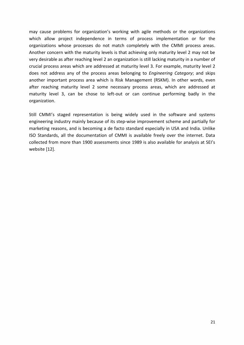
Part 1: Concepts and vocabulary
Part 2: Performing an assessment
Part 3: Guidance on performing an assessment
+ http://www.sqi.gu.edu.au/spice/suite/download.html, 10-02-2011
24
Part 4: Guidance on use for Process Improvement (PI) and Process Capability
Determination (PCD)
Part 5: An exemplar Process Assessment Model (PAM)
Part 6: An exemplar system life cycle process assessment model (only TR published)
Part 7: Assessment of organizational maturity(only TR published)
Part 8: An exemplar process assessment model for IT service management (only TR
published)
Part 9: Capability Target Profiles (under development)
Part 10: Safety Extensions (under development)
Figure 3.2: ISO/IEC 15504 International Standard Parts
+
3.2 – SPICE Structure Part 5 of the ISO/IEC 15504 is commonly known as SPICE. This part presents an exemplar
Process Assessment Model (PAM) which provides a framework for assessing processes
against capability levels, and is organized into two dimensions:
Process Dimension
Capability Dimension
Process Dimension contains all those necessary processes which need to be evaluated
against the capability levels of the Capability Dimension. Each process can be evaluated and
improved to a particular capability level independent of other processes (continuous
improvement), as shown in Figure 3.3. Unlike CMMI, the model does not measure the
maturity level of the whole organization.
+ “Practices in German Automotive Industry”, a presentation by Bernhard Sechser.

25
Figure 3.3: SPICE Continuous Process Improvement
+
It should be noted that processes in the Process Dimension can come from any Process
Reference Model (PRM) and any PAM can be used for capability determination as there is a
number of PAMs and PRMs available (for example, Automotive SPICE and CMMI). Part 2 of
the ISO/IEC 15504 gives requirements for selecting PRMs, PAMs, and defines measurement
framework for process capability, as shown in Figure 2.4.
Figure 3.4: Process Assessment Model (PAM) [4]
+ “CMM, CMMI and ISO 15504 (SPICE)”, a presentation by Malte Foegen and Jürgen Richter

26
3.2.1 – Process Dimension
Process Dimension in part 5 of the ISO/IEC 15504 consists of 48 processes which represent
all the necessary elements of product, and come from ISO 12207 (Software Lifecycle
Processes). These processes state their outcomes using base practices (basic professional
practices) and also provide other advices such as process work products. Any of these
processes can attain any of the defined capability levels. These processes are divided into
three life cycle process categories according to their purpose. Each category further divides
these processes into groups according to the type of activity they perform. These life-cycle
process categories and their subsequent groups are listed below, whereas Figure 3.5 shows
all the processes with their corresponding category and group.
Primary Life Cycle Processes Category
Acquisition Process Group (ACQ)
5 processes
Engineering Process Group (ENG)
10 processes
Supply Process Group (SPL)
3 processes
Operation Process Group (OPE)
2 processes
Supporting Life Cycle Processes Category
Support Process Group (SUP)
10 processes
Organizational Life Cycle Processes Category
Management Process Group (MAN)
5 processes
Process Improvement Process Group (PIM)
3 processes
Resource and Infrastructure Process Group (RIN)
4 processes
Reuse Process Group (REU)
3 processes

27
Figure 3.5: SPICE Process Dimension
+
3.2.2 – Capability Dimension
Capability Dimension contains 6 capability levels that can be reached by the processes.
These capability levels are similar to the CMMI’s capability levels but are different from
CMMI’s maturity levels. Each capability level, from level 1 onwards, further contains one or
more Process Attributes (PA). To reach a capability level, processes need to satisfy that
level’s process attributes. Each PA contains one or more Generic Practices which needs to be
performed in order to satisfy the corresponding PA. These generic practices are general to all
processes and can be applied to any process. Only level 1 further contains base practices
which are specific to each process. A short description of these levels and their
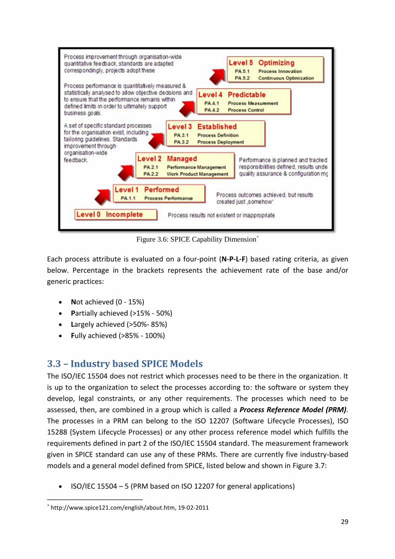
corresponding process attributes is given below and shown in Figure 3.6:
Level 0: Incomplete – A process is incomplete if either it is not performed at all or has
failed to achieve its objective and does not generate any considerable outputs. This
level does not contain any process attributes.
Level 1: Performed – A process acquires performed level status when its objectives
are generally achieved. Although the process is not thoroughly planned and
+ http://www.spice121.com/english/about.htm, 15-02-2011

28
monitored, but still it is performed when required and produces identifiable outputs.
This level consists of one process attribute:
PA.1.1 Process Performance
Level 2: Managed – A managed level process is planned, executed and monitored
according to the specified methods and produces required and standard work
products fulfilling desired quality within defined timescale and resources. This level
consists of two process attributes:
PA.2.1 Performance Management
PA.2.2 Work Product Management
Level 3: Established – An established process is a performed and managed process
which is defined using the best practices of software engineering. Individual
implementations of the process are tailored from organization’s standard processes
and acquire all necessary resources to produce outcomes. This level contains two
process attributes:
PA.3.1 Process Definition
PA.3.2 Process Deployment
Level 4: Predictable – At predictable level, while performing the defined process,
detailed measurements are collected and analyzed which help in quantitatively
understand the capability and improved predictability of the process. Process
performance and process outcomes are quantitatively managed and are working
within defined limits [13]. This level contains two process attributes:
PA.4.1 Process Measurement
PA.4.2 Process Control
Level 5: Optimizing – At this level, quantitative objectives of a process are defined
based on the organization’s business goals, and are permanently tracked. Standard
processes are continuously analyzed and improved, if needed, based upon the
feedback; innovative techniques and approaches are tried; and less effective
processes are modified to better suit the current and future business goals.
Performance of the process is optimized to meet current and future business needs,
and the process achieves repeatability in meeting its defined business goals [13]. This
level also has two process attributes:
PA.5.1 Process Innovation
PA.5.2 Process Optimization
29
Figure 3.6: SPICE Capability Dimension
+
Each process attribute is evaluated on a four-point (N-P-L-F) based rating criteria, as given
below. Percentage in the brackets represents the achievement rate of the base and/or
generic practices:
Not achieved (0 - 15%)
Partially achieved (>15% - 50%)
Largely achieved (>50%- 85%)
Fully achieved (>85% - 100%)
3.3 – Industry based SPICE Models The ISO/IEC 15504 does not restrict which processes need to be there in the organization. It
is up to the organization to select the processes according to: the software or system they
develop, legal constraints, or any other requirements. The processes which need to be
assessed, then, are combined in a group which is called a Process Reference Model (PRM).
The processes in a PRM can belong to the ISO 12207 (Software Lifecycle Processes), ISO
15288 (System Lifecycle Processes) or any other process reference model which fulfills the
requirements defined in part 2 of the ISO/IEC 15504 standard. The measurement framework
given in SPICE standard can use any of these PRMs. There are currently five industry-based
models and a general model defined from SPICE, listed below and shown in Figure 3.7:
ISO/IEC 15504 – 5 (PRM based on ISO 12207 for general applications)
+ http://www.spice121.com/english/about.htm, 19-02-2011

30
SPICE for SPACE PRM
MEDISPICE
AUTOMOTIVE SPICE
OOSPICE
IT Governance SPICE
Banking SPICE (under development)
Figure 3.7: SPICE Capability Dimension+
In the next chapter, Automotive SPICE is explored in more details.
3.4 – Summary and Concluding Remarks ISO/IEC 15504 or SPICE is an effective method of improving the performance of an
organization’s software processes. It does not only define the process improvement strategy
but also provides a way to determine the capability of processes through assessment. Unlike
CMMI-DEV, it does not rate the overall maturity of an organization. It defines 6 capability
levels which can be achieved by any number of processes in the organization (continuous
improvement). Capability levels defined in CMMI-DEV are similar (but not same) to the
capability levels defined in SPICE. Another important thing is that SPICE’s capability levels
should not be confused with CMMI’s maturity levels. Reaching a particular maturity level in
CMMI means organization has successfully deployed all those fixed process areas which are
grouped in that maturity level; whereas reaching a particular capability level in SPICE means
that “any of the processes” contained in SPICE are performing with a certain capability.
Unlike CMMI-DEV, the SPICE does not fix the processes to be deployed and assessed in the
organization. Organizations can select processes according to their business requirements. +
”ISO/IEC 15504 (SPICE)”, a status report by Tery Rout and Alec Dorling
31
These processes can come from other ISO standards, such as ISO/IEC 12207 and ISO/IEC
15288. This gives organizations much flexibility in terms of process coverage, and makes
SPICE more adaptable to industry-specific software processes. Moreover, organizations can
improve any number of processes up to any of the 6 capability levels according to their
business goals, which means that different processes can operate at different capability
levels at the same time, unlike CMMI-DEV maturity levels where all the process areas
belonging to a certain maturity level should be implemented together and should be
performed with the same intensity.
SPICE and CMMI-DEV, both address continuous process improvement. SPICE defines 6
capability levels as compared to CMMI-DEV’s 4 capability levels. This means that a process in
SPICE can continue to improve up to the 6th capability level independent of the other
processes, whereas in CMMI-DEV a process area which reaches 4th capability level cannot
improve itself further independently. To further improve a process area, some high maturity
process areas are needed to be deployed which help in improving all other process areas.
This means that even in CMMI-DEV’s continuous process improvement, processes cannot
continue to improve independently after reaching 4th level.
Performing SPICE assessments is easier than performing CMMI appraisals. In SPICE, the
scope of assessment can range from one process in a project, a single project or an
organizational unit to a complete organization-wide assessment which means assessments
can be very quick or very detailed as well. Whereas in CMMI, to get a maturity level rating
Class A assessments must be performed across the organization.
There exist a lot of concerns as well with SPICE. For example, its documents are not available
freely over the internet and are quite expensive to purchase which decreases it knowledge
and awareness level in industry and especially at academic institutes as compared to CMMI
which is available free of cost. SPICE does not provide best practices, and defines work
products in a very generic way which sometimes becomes too generic and requires a lot of
further assistance for implementation. It is also difficult to compare the assessment results
of one organization to another organization’s results because of the selection of different
processes at different organization. On the other hand, CMMI appraisals provide a single
maturity level rating of an organization which can be easily compared with other
organizations’ maturity rating. Another concern is if processes can be improved
independently of other processes and different processes can work at different capability
levels, then does it make sense to have high capability level development processes with low
capability testing processes or low capability management processes?
Work is going on in the part 9 (Target Project Profiles) of the SPICE standard to define target
profiles for assessment which will help in comparing the assessment results of different
organizations. Upon users requests, part 7 (Assessment of Organizational Maturity) of the

32
SPICE standard has defined a way to assess the overall maturity of the organization like
CMMI’s maturity levels. Initial draft of this part is available as a Technical Report.

33
Chapter 4 – Automotive SPICE
(A-SPICE)
4.1 – Overview Nowadays, modern vehicles are known for their performance and quality, and are valued for
money and innovative technology features they include. Most of these current and future
innovations are based on electronics and use of software. The electronic control units (ECUs)
are becoming more dependent on the use of software. According to a study, size of software
in a modern automobile is between 40 to 90 Megabytes. Still there is this ever increasing
demand on the software to guarantee the efficiency and responsiveness of the embedded
functionality for the vehicle drivers; leading to the fact that 85% of the functionality of
modern day’s vehicles is controlled by software [12].
This raises a number of concerns related to hardware and software interactions, safety
issues due to the systems malfunctioning and others. One of the major challenges is to
manage the quality of this increasingly complex software on which vehicle functions are
dependent. One approach to address these concerns is to use and reuse the standardized
processes and best practices from the industry. The motor vehicle manufacturers are now
focusing on the software capability of their suppliers and demand assessments of suppliers’
software capability both before and during the projects.
Different OEMs (Original Equipment Manufacturers) have been using different approaches
(as listed below) to assess the capability or maturity of their software suppliers [17]:
Audi: both ISO/IEC TR 15504 and CMM
BMW: Internal questionnaire
DAG: ISO/IEC TR 15504 (since 1999)
Porsche: Internal questionnaire
VW: SW-CMM 1.1 and internal questionnaire
This created the need for developing a “common framework for assessing the suppliers in
automotive industry” which resulted in the creation of Automotive SPICE (A-SPICE).
4.1.1 – Automotive SPICE Objectives
“In a major initiative, the Automotive Special Interest Group (SIG), a joint special interest
group of The SPICE User Group and The Procurement Forum, launched the Automotive
SPICE® initiative together with the major motor vehicle manufacturers to develop a ‘common
framework for the assessment of suppliers in the Automotive Industry’. The result is the

34
publication of the Automotive SPICE® Process Assessment Model (PAM) together with the
associated Process Reference Model (PRM)” [18].
The goal was to create an international standard specific to automobile industry that could
be used by the automobile manufacturers to assess their suppliers’ software capability.
Nothing new was created; instead the existing SPICE standard (ISO/IEC 15504) was used and
adapted to the automobile manufacturer requirements by tailoring it and selecting the most
relevant subset of the processes from SPICE. It has published its own process reference
model and process assessment model.
The members of the Automotive SIG include:
AUDI AG, BMW Group, Daimler AG, Fiat Auto S.p.A., Ford Werke GmbH, Jaguar, Land Rover,
Dr. Ing. h.c. F. Porsche AG, Volkswagen AG and Volvo Car Corporation.
4.2 – Automotive SPICE PRM Automotive SPICE Process Reference Model (PRM) defines the processes composing ASPICE,
and complies with the requirements of the part 2 of the ISO/IEC 15504. There are 31
processes in the SPICE PRM which are not completely same as specified in the general SPICE
PRM. It excludes 21 processes of general SPICE PRM and includes 5 new processes from
ISO/IEC 12207 model which are more related to automotive industry [17].
The Automotive SPICE PRM is used together with the process performance and process
capability indicators defined in the Automotive SPICE Process Assessment Model (PAM) to
perform an assessment of the suppliers’ capability [19].
4.3 – Automotive SPICE PAM Automotive SPICE Process Assessment Model (PAM) provides a detailed method of
performing assessment of software suppliers’ process capability in accordance with the
requirements of part 2 of the ISO/IEC 15504. It is used in conjunction with the Automotive
SPICE PRM to perform assessment.
The Automotive SPICE PAM contains all the necessary details (so called performance and
capability indicators) to evaluate the process capability. Like SPICE, it is also organized into
two dimensions: Process Dimension and Capability Dimension [1].
4.3.1 – A.SPICE Process Dimension
Process dimension consists of 31 life cycle processes. Each process specifies its purpose,
process outcomes, base practices to perform the process, and process output work
products.
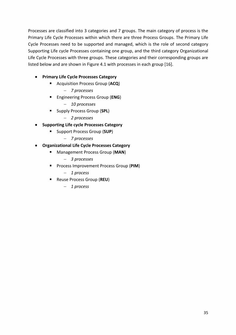
35
Processes are classified into 3 categories and 7 groups. The main category of process is the
Primary Life Cycle Processes within which there are three Process Groups. The Primary Life
Cycle Processes need to be supported and managed, which is the role of second category
Supporting Life cycle Processes containing one group, and the third category Organizational
Life Cycle Processes with three groups. These categories and their corresponding groups are
listed below and are shown in Figure 4.1 with processes in each group [16].
Primary Life Cycle Processes Category
Acquisition Process Group (ACQ)
7 processes
Engineering Process Group (ENG)
10 processes
Supply Process Group (SPL)
2 processes
Supporting Life cycle Processes Category
Support Process Group (SUP)
7 processes
Organizational Life Cycle Processes Category
Management Process Group (MAN)
3 processes
Process Improvement Process Group (PIM)
1 process
Reuse Process Group (REU)
1 process

36
Figure 4.1: Automotive SPICE Process Dimension
4.3.2 – A.SPICE Capability Dimension
Automotive SPICE capability dimension uses six capability levels for process improvement.
Levels 1 to 5 are further assigned with process attributes which represent a particular aspect
of the process capability. Each process can achieve any desired capability level independent
of other processes (continuous improvement).
PRIMARY Life Cycle Processes ORGANIZATIONAL
Life Cycle Processes
SUPPORTING Life Cycle Process
Acquisition Process Group (ACQ)
ACQ.3 Contract Agreement
ACQ.4 Supplier Monitoring
ACQ.11 Technical Requirements
ACQ.12 Legal and Administrative
Requirements
ACQ.13 Project Requirements
ACQ.14 Request for Proposals
ACQ.15 Supplier Qualification
Engineering Process Group (ENG)
ENG.1 Requirements Elicitation
ENG.2 System Requirements Analysis
ENG.3 System Architectural Design
ENG.4 Software Requirements Analysis
ENG.5 Software Design
ENG.6 Software Construction
ENG.7 Software Integration Test
ENG.8 Software Testing
ENG.9 System Integration Test
ENG.10 System Testing
Management Process Group (MAN)
MAN.3 Project Management
MAN.5 Risk Management
MAN.6 Measurement
Process Improvement Process Group (PIM)
PIM.3 Process Improvement
Reuse Process Group (REU)
REU.2 Reuse Program Management Supply Process Group (SPL)
SPL.1 Supplier Tendering
SPL.2 Product Release
Support Process Group (SUP)
SUP.1 Quality Assurance SUP.8 Configuration Management
SUP.2 Verification SUP.9 Problem Resolution Management
SUP.4 Joint Review SUP.10 Change Request Management
SUP.7 Documentation

37
Whether a particular capability level is achieved by a process is determined by the fulfillment
of that level’s process attributes *1]. These capability levels and their corresponding process
attributes are same as those defined in SPICE model (in the previous chapter) and shown in
Figure 4.2.
Figure 4.2: Capability Dimension
+
4.3.3 – Rating Scale Calibration
A four point rating scale (N-P-L-F) has been defined in the ISO/IEC 15504 which is used to
measure the extent of achievement of any capability level, process attributes, and base and
generic practices of the processes.
N Not Achieved (0 – 15%)
P Partially Achieved (>15% – 50%)
L Largely Achieved (>50% – 85%)
F Fully Achieved (>85% – 100%)
In order to achieve a specific capability level, all process attributes of that level must be at
least Largely achieved, and all the process attributes at lower levels must be Fully achieved
[1]. This calculation is explained in Table 4.1. Figure 4.3 gives a short description of each
rating scale.
+ http://portal.automotive-his.de/, 20-02-2011

38
Figure 4.3: Rating Scale Calibration
+
Capability Level Process Attributes Rating
Level 1 PA 1.1 Largely or Fully achieved
Level 2 PA 1.1
PA 2.1
PA 2.2
Fully achieved
Largely or Fully achieved
Largely or Fully achieved
Level 3 PA 1.1
PA 2.1
PA 2.2
PA 3.1
PA 3.2
Fully achieved
Fully achieved
Fully achieved
Largely or Fully achieved
Largely or Fully achieved
Level 4 PA 1.1
PA 2.1
PA 2.2
PA 3.1
PA 3.2
PA 4.1
PA 4.2
Fully achieved
Fully achieved
Fully achieved
Fully achieved
Fully achieved
Largely or Fully achieved
Largely or Fully achieved
Level 5 PA 1.1
PA 2.1
PA 2.2
PA 3.1
PA 3.2
PA 4.1
PA 4.2
PA 5.1
PA 5.2
Fully achieved
Fully achieved
Fully achieved
Fully achieved
Fully achieved
Fully achieved
Fully achieved
Largely or Fully achieved
Largely or Fully achieved
Table 4.1: Rating Criteria for SPICE Capability Levels
+ http://portal.automotive-his.de/, 20-02-2011

39
4.4 – HIS Scope – Selected Processes
The German automobile manufacturers Audi, BMW, DaimlerChrysler and Porsche and VW
have been working together in a group, called Hersteller Initiative Software (HIS), to define
and implement common standards in the areas of Standard software modules, Software
test, Flash programming of electronic control units (ECU), Process assessments, and
Simulation and tools. A Working Group (WG) with the name “Assessment” was formed
within HIS group which was responsible to create a common approach for assessing the
software capability of the suppliers as all the HIS members were using different approaches
for assessing their suppliers [17].
As a result, a subset of 15 processes was selected, called HIS Scope, which was based on the
Automotive SPICE’s Process Reference Model (PRM) and was to be assessed by each
manufacturer in the HIS group. HIS Scope is not a PRM itself but only gives a subset of
necessary processes for automotive industry, and provides an “exchange framework” to
exchange the results of the assessments with the manufacturers. HIS Scope is also being
used by other industries as a starting point to improve processes and to set scope of
assessments [20].
There are 3 categories, 4 groups, and 15 processes in the HIS Scope. These are listed below
and shown in Figure 4.4.
Primary Life Cycle Processes Category Acquisition Process Group (ACQ)
ACQ.4 Supplier Monitoring Engineering Process Group (ENG)
ENG.2 System Requirements Analysis
ENG.3 System Architectural Design
ENG.4 Software Requirements Analysis
ENG.5 Software Design
ENG.6 Software Construction
ENG.7 Software Integration Test
ENG.8 Software Testing
ENG.9 System Integration Test
ENG.10 System Testing
Supporting Life cycle Processes Category Support Process Group (SUP)
SUP.1 Quality Assurance
SUP.8 Configuration Management
SUP.9 Problem Resolution Management
SUP.10 Change Request Management

40
Organizational Life Cycle Processes Category Management Process Group (MAN)
MAN.3 Project Management
Figure 4.4: HIS Scope Processes+
This is the list of minimum processes to be evaluated by each member of HIS group.
Evaluating processes ENG.2, ENG.3 and ENG.9, ENG.10 depends upon the scope of the
project (software/system). ACQ.4 is optional depending upon if subcontractors are involved
or not. This list may be extended to assess more related processes, if required [17].
4.5 – Assessment Indicators The Process Assessment Model presents a rule to evaluate the capability of a process. That
is, to determine the capability level of a process, first measure that up to what extent the
process has achieved the Process Attributes of that level. This can be measured using
Assessment Indicators. There are two types of assessment indicators which indicate the
achievement of Process Attributes, listed below and shown in Figure 4.5 [21]:
Process Capability Indicators (apply to capability levels 1 to 5)
Process Performance Indicators (apply exclusively to capability level 1)
+ http://portal.automotive-his.de/, 20-02-2011

41
Figure 4.5: Process Assessment Indicators [21]
4.5.1 – Process Capability Indicators
Process Capability Indicators apply to all the process attributes in all the capability levels (1-
5). The definition of each capability indicator is same for all the processes. These indicators
provide evidence of achievement of process attributes at each level using generic practices
and generic resource. Each process attribute has two types of process capability indicators:
Generic Practices (GP) are general kind of activities which help in implementing the
attributes’ characteristics at any level. They are not process specific, instead, they are
process attribute specific, and can be implemented by any process accordingly. Most
of these practices are management related practices which support the process
performance characteristics achieved at level 1.
Generic Resources (GR) are the related resources which are needed while
performing the generic practices to achieve the process attributes of a level. They
include human resources, tools, methods and infrastructure [21].
A list of generics practices with their corresponding process attributes for all capability levels
is given in the Annex B.
4.5.2 – Process Performance Indicators
Process Performance Indicators apply to each process individually at level 1. These indicators
help in explicitly achieving the defined purpose of every process. Achieving the purpose of a
process is a very basic requirement to prove the capability of a process. These indicators are
defined separately for each process to reach level 1. In other words, in order to achieve the
process attribute of capability level 1, each process has to perform process-specific base

42
practices to generate required work products. The two types of process performance
indicators are:
Base Practices (BP) are the activities which explicitly help in achieving the purpose of
a process which is required to achieve the process attribute at level 1. Although,
these are process specific activities but still they only define “what” to do without
indicating “how” to do.
Work Products (WP) are either used while performing the base practices, are
produced as a result, or are both. Work products produced by performing the
process are distinct and help in fulfilling process purpose [21].
The structure of the assessment indicators at different levels is elaborated in Figure 4.6.
Figure 4.6: Assessment Indicators Structure
4.6 – Recording Assessment Results Assessment indicators verify that certain practices are being performed, and a certain
process has a certain capability. This verification comes from the observable evidences
which are collected during the assessment process. These evidences could either be the
examination of the work products of the processes being evaluated, or the statements given
by the performers and the managers of the processes during the interviews. The collected
evidences must be recorded in a format that clearly represents the rating level of the

43
associated indicator. The result of evaluation process is a set of “process profiles” of the
processes which were assessed. A process profile contains the ratings of the process
attributes of the corresponding process which shows assessor’s judgment about the
achievements of those attributes [21].
To find out the capability level of a process, its process attributes achievement for a
particluar level must be measured first. To measure the process attributes at any level, the
corresponding Generic practices of each process attributes must be measure first. Rating
generic pactice GP 1.1.1 of process attribute at level 1 is a special case. To find out the rating
of GP 1.1.1 for a particular process, all corresponding base practice (BP) ratings of that
proces must be measured first. This is explained in the examples below.
HIS Working Group has defined the following formats to record the results of the
assessment and hence determine the capability levels of the processes. Examples of these
formates are shown in figures 4.7, 4.8 and 4.9 [17].
*Figure 4.7: Example of Generic and Base Practices Assessment Results +
Figure 4.7 shows an example of measuring the rating of GPs of process attributes PA 1.1, PA
2.1 and PA 2.2 for capability levels 1 and 2 for the process “ACQ.4 Supplier Monitoring”. It is
clearly shown that GP 1.1.1 is a cumulative rating of all the corresponding base practice
ratings.
GP ratings further cumulate to the corresponding process attribute ratings. These attribute
ratings for several processes are shown in Figure 4.8. These ‘process attribute ratings’
further help in deciding the capability level rating of each process using the rating criteria,
that is, “in order to achieve a specific capability level, all process attributes of that level must
+ http://portal.automotive-his.de/, 20-02-2011
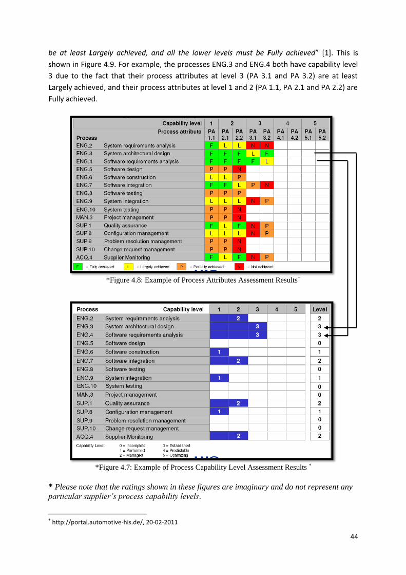
44
be at least Largely achieved, and all the lower levels must be Fully achieved” [1]. This is
shown in Figure 4.9. For example, the processes ENG.3 and ENG.4 both have capability level
3 due to the fact that their process attributes at level 3 (PA 3.1 and PA 3.2) are at least
Largely achieved, and their process attributes at level 1 and 2 (PA 1.1, PA 2.1 and PA 2.2) are
Fully achieved.
*Figure 4.8: Example of Process Attributes Assessment Results
+
*Figure 4.7: Example of Process Capability Level Assessment Results
+
* Please note that the ratings shown in these figures are imaginary and do not represent any
particular supplier’s process capability levels.
+ http://portal.automotive-his.de/, 20-02-2011

45
4.7 – Summary and Concluding Remarks Automotive SPICE is an industry-specific version of ISO/IEC 15504 or SPICE which provides
automotive industry-specific process improvement and assessment methodologies. It can be
used both by the software supplier to improve its software process performance, as well as
by the original manufacturer to assess the capability of supplier’s software processes. A-
SPICE defines its own Process Reference Model and Process Assessment Model which are
consistent with the requirements of part 2 of the ISO/IEC 15504. The major difference is that
those software processes are chosen which best suit the automotive industry and, in
addition, industry-specific terminologies and preferences are used while describing
processes. Both PRM and PAM of A-SPICE are available freely over the internet. A group of
German automobile manufacturers has also created a subset of processes, called HIS Scope,
based on A-SPICE processes. HIS Scope is required to be assessed by all software suppliers in
this industry.
The ISO/IEC 15504-5 as an exemplary PAM contains
3 Process Categories
9 Process Groups
48 Processes
The Automotive SPICE PAM consists of
3 Process Categories
7 Process Groups
31 Processes
The HIS Scope consists of:
3 Process Categories
4 Process Groups
15 Processes
One of the main differences in A-SPICE as compared to SPICE and CMMI-DEV is that
Acquisition process group is made more detailed and elaborated according to automotive
industry needs as it is a very common trend among Original Equipment Manufacturers
(OEMs) in automotive industry to involve software suppliers. Furthermore, A-SPICE
processes are made adaptable to the parallel hardware/software/system development and
multiple software release cycles approaches of automotive industry. Change Request
Management and Configuration Management processes are of major concern in this regard.
A main concern with the HIS Scope of Automotive SPICE is that it is missing some important
processes, such as, Risk Management, Measurement, and Process Improvement. But still it
can be a “good start” for the process improvement journey.

46
Chapter 5 – Comparison & Mapping
Process improvement is not an easy task by any means. It is costly as well as lengthy and
time-taking. Purpose of both of the models, CMMI and SPICE/A-SPICE, is to provide an
efficient way to improve and assess the processes. Both of the models, therefore, have a
number of similarities but considerable differences as well, in terms of concepts and
contents due to the fact that they focus on different areas in some cases, and mostly
because they are structured differently. For example, in Automotive SPICE, engineering
processes are represented by 10 different processes (from ENG.1 to ENG.10), whereas CMMI
has only 6 process areas for Engineering category (REQM, RD, TS, PI, VER, and VAL) [5].
Comparison between CMMI-DEV and Automotive SPICE can be made in several perspectives,
but we have considered only two aspects for comparison. These are: comparison with
respect to their structure, and their contents.
5.1 – Structural Comparison CMMI presents different models for different application areas. These models constitute the
CMMI constellations. Each constellation contains a set of 16 core processes areas, and also
includes the respective application specific process areas. These constellations are not
software specific but can be applied to other systems engineering areas as well.
CMMI for Development (CMMI-DEV)
CMMI for Acquisition (CMMI- ACQ)
CMMI for Services (CMMI-SVC)
ISO/IEC 15504 (SPICE), on the other hand, does not specify any particular process or process
category (Dev, Acq, Svc). Instead, it gives requirements for selecting processes for a process
reference model PRM. Process in PRM can belong to any model, for example ISO/IEC 12207
(software lifecycle processes) or ISO/IEC 15288 (system lifecycle processes), and can belong
to any process category, for example Acquisition, Engineering, Management, Supply,
Support. In other words, a PRM can have a combination of any required processes belonging
to any category. There exist some industry-specific variations of SPICE who have defined
their own PRM containing relevant processes. These are:
ISO/IEC 12207 (standard for general applications)
SPICE for SPACE
MEDISPICE
Automotive SPICE
OOSPICE
IT Governance SPICE
Banking SPICE (under development)

47
CMMI-DEV is more suitable for a comparison with Automotive SPICE, since only there do we
find development related processes. CMMI-ACQ can also be a good candidate as it puts
more focus on acquisition activities which are briefly dealt in CMMI-ACQ.
5.1.1 – Representation Models
The most important difference between CMMI and Automotive SPICE is CMMI’s two
representation models:
Continuous Representation
This representation model is similar to SPICE/A-SPICE in the sense that it contains 4
capability levels, and process areas are divided into 4 categories. Each process area
can reach any individual capability level independent of other process areas.
Staged Representation
This representation model, however, is totally different from SPICE/A-SPICE. Instead
of capability levels, it contains 5 maturity levels. Each maturity level contains a
predefined set of process areas which need to be implemented together. After
implementing all the process areas of one level, organization can move to the next
level. This is the most widely used model among CMMI users [1].
SPICE/A.SPICE, on the other hand, has only “Continuous Representation” with 6 capability
levels which can be achieved by any process. Therefore, structure-wise continuous
representation of CMMI is more suitable for comparison with SPICE/A-SPICE capability
levels. However, CMMI’s staged representation and SPICE/A-SPICE capability levels can be
compared content-wise. Table 5.1 maps CMMI-DEV capability levels with SPICE/A-SPICE
capability levels.
CMMI – DEV V1.3
Capability Levels
Automotive SPICE
Capability Levels
0 – Incomplete 0 – Incomplete
1 – Performed 1 – Performed
2 – Managed 2 – Managed
3 – Defined 3 – Established
- 4 – Predictable
- 5 – Optimizing
Table 5.1: CMMI and SPICE/A-SPICE Capability Levels
5.1.2 – Quantitative Values
Another difference between their structures is that SPICE and A-SPICE process models are
more finely structured having 9 process groups with 48 processes in SPICE, 7 process groups
with 31 processes in Automotive SPICE, 4 process groups with 15 processes in HIS Scope
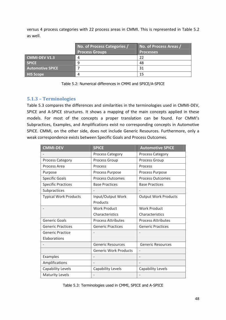
48
versus 4 process categories with 22 process areas in CMMI. This is represented in Table 5.2
as well.
No. of Process Categories / Process Groups
No. of Process Areas / Processes
CMMI-DEV V1.3 4 22
SPICE 9 48
Automotive SPICE 7 31
HIS Scope 4 15
Table 5.2: Numerical differences in CMMI and SPICE/A-SPICE
5.1.3 – Terminologies
Table 5.3 compares the differences and similarities in the terminologies used in CMMI-DEV,
SPICE and A-SPICE structures. It shows a mapping of the main concepts applied in these
models. For most of the concepts a proper translation can be found. For CMMI’s
Subpractices, Examples, and Amplifications exist no corresponding concepts in Automotive
SPICE. CMMI, on the other side, does not include Generic Resources. Furthermore, only a
weak correspondence exists between Specific Goals and Process Outcomes.
CMMI-DEV SPICE Automotive SPICE
- Process Category Process Category
Process Category Process Group Process Group
Process Area Process Process
Purpose Process Purpose Process Purpose
Specific Goals Process Outcomes Process Outcomes
Specific Practices Base Practices Base Practices
Subpractices - -
Typical Work Products Input/Output Work
Products
Output Work Products
- Work Product
Characteristics
Work Product
Characteristics
Generic Goals Process Attributes Process Attributes
Generic Practices Generic Practices Generic Practices
Generic Practice
Elaborations
- -
- Generic Resources Generic Resources
Generic Work Products -
Examples - -
Amplifications - -
Capability Levels Capability Levels Capability Levels
Maturity Levels - -
Table 5.3: Terminologies used in CMMI, SPICE and A-SPICE

49
Furthermore, SPICE/A-SPICE uses a two-tier hierarchy for elaborations consisting of process
attributes PA’s and their corresponding practices (generic/base); whereas CMMI introduces
a three-tier hierarchy for elaborations consisting of goals (generic/specific), practices
(generic/specific), and sub practices with a lot of informative text [1].
5.2 – Contents Comparison CMMI and SPICE/A-SPICE both contain contents which are similar in both models, some of
them are addressed partially in one, and still some are not present in the other.
5.2.1 – Scope
If we talk in terms of Scope of the models, SPICE (specifically talking ISO/IEC 15504 part 5) is
very much software centric. CMMI, on the other hand, addresses both Systems Engineering
and Software Engineering through its Technical Solution (TS) process area. It describes its
practices in such a general way that it can fit to many application domains (such as
hardware, software and systems engineering), making CMMI’s concepts comparatively
abstract. This wider scope of CMMI makes it more popular among large system integrator
and acquirers. To cover systems engineering concepts in SPICE as well Part 6 of ISO/IEC
15504 is created which includes processes from the ISO 15288 (systems lifecycle processes)
and which can be mapped partially to CMMI [12].
Automotive SPICE includes both of the concepts of software as well as systems engineering
but they are very much specific to the automotive industry which makes it a best choice only
for automotive industry.
5.2.2 – Categories / Groups
CMMI, SPICE and Automotive SPICE, all of them have different number of process categories
or process groups. But all of them include the categories or groups which cover the
development of software intensive products. These are:
Process Management
Project Management
Engineering
Support

50
CMMI – DEV Process Categories
SPICE Process Groups
Automotive SPICE Process Groups
Process Management Process Improvement (PIM) Reuse (REU)
Process Improvement (PIM) Reuse (REU)
Project Management Management (MAN) Acquisition (ACQ) Resource and Infrastructure (RIN)
Management (MAN) Acquisition (ACQ)
-
Engineering Engineering (ENG) Engineering (ENG)
Support Support (SUP)
Support (SUP)
- Operation (OPE)
-
- Supply (SPL)
Supply (SPL)
Table 5.4: Mapping of CMMI-DEV Categories to SPICE and A-SPICE Process Groups
It can be observed from Table 5.4 that Process Improvement (PIM) and Reuse (REU) groups
of SPICE/A-SPICE and Process Management category of CMMI partially address each other’s
processes. Management (MAN) and Acquisition (ACQ) groups of SPICE/A-SPICE are partially
addressed by CMMI’s Management category. Resource and Infrastructure (RIN) of SPICE is
addressed partially by the same category in CMMI, but this group is not included in
Automotive SPICE. Operation (OPE) process group of SPICE is excluded from Automotive
SPICE and is not addressed in CMMI as well. CMMI does not cover Supply (SPL) process
group of SPICE/A-SPICE.
5.2.3 – Process Areas / Processes
There does not exist any exact or direct or a simple mapping between CMMI and SPICE/A-
SPICE. To limit the comparison scope, we only talk about processes of Automotive SPICE and
CMMI in this section. There are a number of differences between these models when talking
about process mapping. For example:
CMMI-DEV does not address or very weakly addresses the following processes:
SPL.1 – Supplier Tendering
SPL.2 – Product Release
REU.2 – Reuse Program Management
Following processes are not completely addressed in CMMI-DEV:
Processes from ACQ.11 to ACQ.15 in Acquisition process group (ACQ)
SUP.7 – Documentation; (it is covered generally in CMMI)
SUP.9 – Problem Resolution Management
SUP.10 – Change Request Management
On the other hand, Automotive SPICE does not address:
Decision Analysis and Resolution (DAR)

51
Integrated Product and Project Management (IPPM)
Organizational Training (OT)
The following processes are partially addressed in Automotive SPICE:
Quantitative Project Management (QPM)
Causal Analysis & Resolution (CAR)
Organizational Process Performance (OPP)
Organizational Process Focus (OPF)
Organizational Process Definition (OPD)
Further differences include:
Some processes are addressed more thoroughly in CMMI but not in
Automotive SPICE. Similarly, some processes are addressed more thoroughly
in Automotive SPICE but not in CMMI.
CMMI contains detailed level “guidelines about implementing” the process
areas.
Coverage of CMMI’s specific practices vs. base practices and process
outcomes of A-SPICE is not at the same level.
Generic Practices in CMMI do not completely address the Process Attributes
(PA) of capability levels of Automotive SPICE. For example [12]:
PA 2.2 is not explicitly addressed in CMMI.
PA 3.2 and PA 5.1 are not addressed by any generic practice of CMMI.
Instead, it is addressed in some process areas of CMMI: Organizational
Process Focus (OPF), Organizational Process Definition (OPD),
Organizational Training (OT) and Integrated Product and Project
Management (IPPM).
PA 5.1 is addressed by these process areas of CMMI: Organizational
Performance Management (OPM) and Causal Analysis & Resolution
(CAR).
Another difference is that in A-SPICE, processes are more finely grained. For example, in A-
SPICE, Engineering processes are represented by 10 different processes (from ENG.1 to
ENG.10), whereas CMMI has only 6 process areas for Engineering category (REQM, RD, TS,
PI, VER, and VAL) [5].
The other most obvious differences of A-SPICE as compared to CMMI and SPICE include that
Acquisition process category is more detailed and elaborated as automotive industry uses
many parts and component suppliers which requires detailed handling of requirements,
specifications, legal and project requirements between the original manufacturer and the
software suppliers. Besides, it is very important to make sure that adequate hardware and
software is available during prototype development. This is handled by Supply process
category.

52
Processes defined in the A-SPICE are adaptable to automotive industry approaches of
“parallel system/hardware/software development” and “multiple software release cycles”.
Because of this parallel development and multiple release cycles of ECUs, Change Request
Management and Configuration Management processes have become really important to
keep track of the several software versions created during development, as well as those
versions delivered to the manufacturers and finally deployed in the automobiles.
5.2.4 – Process Mapping
As stated earlier, not everything is mapped exactly in both models, some processes are
addressed by more than one processes areas in the other model, and some processes are
not covered at all. Figure 5.1 shows a mapping of HIS Scope processes (a subset of A.SPICE
processes) to the equivalent process areas in CMMI-DEV.
Figure 5.1: Mapping of HIS Scope with CMMI-DEV [1]
Automotive SPICE
ENG.2 System Requirements Analysis
ENG.4 Software Requirements Analysis
SUP.9 Problem Resolution Management
ACQ.4 Supplier Monitoring
ENG.3 System Architectural Design
ENG.5 Software Design
ENG.6 Software Construction
ENG.7 Software Integration Test
ENG.9 System Integration Test
ENG.8 Software Testing
ENG.10 System Testing
MAN.3 Project Management
SUP.8 Configuration Management
SUP.10 Change Request Management
SUP.1 Quality Assurance
CMMI – DEV V1.3
Requirements Development (RD)
Requirements Management (REQM)
Technical Solution (TS)
Product Integration (PI)
Verification (VER)
Validation (VAL)
Project Planning (PP)
Project Monitoring and Control (PMC)
Configuration Management (CM)
Process & Product Quality Assurance (PPQA)
Supplier Agreement Management (SAM)
Causal Analysis and Resolution (CAR)

53
Table 5.5 maps all A-SPICE processes to their equivalent CMMI-DEV processes. Note that a
single A-SPICE process is sometimes mapped to more than one CMMI-DEV processes as the
generic and base practices and output work products of a single A-SPICE process relate to
more than one processes areas’ generic and specific practices and work products in CMMI-
DEV. Also note that processes ACQ.11 – ACQ.15 are partially or weakly addressed in the
CMMI [22].
Automotive SPICE CMMI – DEV 1.3
Acquisition Process Group (ACQ)
ACQ.3 Contract Agreement Supplier Agreement Management (SAM) – weakly
ACQ.4 Supplier Monitoring Supplier Agreement Management (SAM) – partially
ACQ.11 Technical Requirements Supplier Agreement Management (SAM) – weakly
Requirements Management (REQM) – partially
ACQ.12 Legal and Administrative
Requirements
Supplier Agreement Management (SAM) – weakly
Requirements Management (REQM) – partially
ACQ.13 Project Requirements Supplier Agreement Management (SAM) – weakly
Requirements Management (REQM) – partially
ACQ.14 Request for Proposals
ACQ.15 Supplier Qualification
Supplier Agreement Management (SAM) – weakly
Supply Process Group (SPL)
SPL.1 Supplier Tendering -
SPL.2 Product Release -
Engineering Process Group (ENG)
ENG.1 Requirements Elicitation Requirements Development (RD) – partially
Requirements Management (REQM) – partially
ENG.2 System Requirements Analysis Requirements Development (RD) – partially
Requirements Management (REQM) – largely
ENG.3 System Architectural Design Requirements Development (RD) – partially
Requirements Management (REQM) – partially
Technical Solution (TS) – partially
ENG.4 Software Requirements Analysis Requirements Development (RD) – partially
Requirements Management (REQM) – largely
ENG.5 Software Design Requirements Development (RD) – partially
Technical Solution (TS) – partially
ENG.6 Software Construction Technical Solution (TS) – partially
Product Integration (PI) – weakly
ENG.7 Software Integration Test
ENG.8 Software Testing
ENG.9 System Integration Test
ENG.10 System Testing
Product Integration (PI) – partially
Validation (VAL) – partially
Management Process Group (MAN)
MAN.3 Project Management Project Monitoring and Control (PMC) – largely

54
Automotive SPICE CMMI – DEV 1.3
Project Planning (PP) – largely
Causal Analysis & Resolution (CAR) – partially
Process & Product Quality Assurance (PPQA) – partially
Requirements Management (REQM) – partially
MAN.5 Risk Management Risk Management (RSKM) – strongly
Project Planning (PP) ) – weakly
Project Monitoring and Control (PMC) ) – weakly
MAN.6 Measurement Measurement & Analysis (MA) – strongly
Organizational Process Definition (OPD) – weakly
Process Improvement Process Group (PIM)
PIM.3 Process Improvement Causal Analysis & Resolution (CAR) – largely
Organizational Process Focus (OPF) – weakly
Organizational Performance Management (OPM) –
weakly
Organizational Process Performance (OPP) – weakly
Reuse Process Group (REU)
REU.2 Reuse Program Management -
Support Process Group (SUP)
SUP.1 Quality Assurance Process & Product Quality Assurance (PPQA) – strongly
SUP.2 Verification Verification (VER) – partially
SUP.4 Joint Review Process & Product Quality Assurance (PPQA) – strongly
Verification (VER) – partially
Project Monitoring and Control (PMC) ) – partially
Supplier Agreement Management (SAM) – weakly
SUP.7 Documentation Technical Solution (TS) – partially
Configuration Management (CM) – weakly
SUP.8 Configuration Management Configuration Management (CM) – strongly
SUP.9 Problem Resolution Management Causal Analysis & Resolution (CAR) – weakly
SUP.10 Change Request Management Configuration Management (CM) – weakly
Table 5.5: Mapping A-SPICE and CMMI Processes
5.2.5 – CMMI Maturity Levels Processes
The staged representation of CMMI-DEV groups certain process areas into organizational
maturity levels. Each process area has a number of specific goals and practices, and each
maturity level has a number of generic goals and practices. In A-SPICE, processes have a
number of outcomes which are implemented through the process attributes at each
capability level using base and generic practices.

55
To establish an equivalent Automotive SPICE process profile for the CMMI maturity levels, all
of the specific and generic practices of each process area in each maturity level were
compared to the outcomes and process attributes of A-SPICE processes. For an A-SPICE
process to be included in a certain CMMI maturity level, all of its outcomes and certain
process attributes must be addressed by the specific and generic practices of equivalent
CMMI processes at that level. An A-SPICE process cannot be placed in at a maturity level
unless all of its outcomes are covered [23].
Table 5.6 provides A-SPICE process profile equivalent to CMMI maturity level process areas.
Note that at each level, A-SPICE processes are required to implement certain process
attributes (PA). Each level also includes the processes from previous levels, and these
processes are required to achieve the process attributes stated in the current maturity level.

56
Levels CMMI-DEV V1.3 Processes Automotive SPICE Processes
1 Initial / Performed
No processes No direct Equivalent
2 Managed / Managed
Requirements Management (REQM) Project Planning (PP) Project Monitoring and Control (PMC) Measurement & Analysis (MA) Configuration Management (CM) Supplier Agreement Management (SAM) Process & Product Quality Assurance (PPQA)
ACQ.3 Contract Agreement ACQ.4 Supplier Monitoring SUP.7 Documentation SUP.8 Configuration Management SUP.1 Quality Assurance MAN.3 Project Management MAN.6 Measurement SUP.10 Change Request Management PA 1.1 PA 2.1 PA 2.2
3 Defined / Established
Decision Analysis & Resolution (DAR) Product Integration (PI) Requirements Development (RD) Technical Solution (TS) Verification (VER) Validation (VAL) Organizational Process Focus (OPF) Organizational Process Definition (OPD) Integrated Project Management (IPM) Risk Management (RSKM) Organizational Training (OT)
ENG.1 Requirements Elicitation ENG.2 System Requirements Analysis ENG.3 System Architectural Design ENG.4 Software Requirements Analysis ENG.5 Software Design ENG.6 Software Construction ENG.7 Software Integration Test ENG.8 Software Testing ENG.9 System Integration Test ENG.10 System Testing SUP.2 Verification SUP.4 Joint Review MAN.5 Risk Management Level 2 processes and process attributes, plus PA 3.1 PA 3.2
4 Quantitatively Managed / Predictable
Organizational Process Performance (OPP) Quantitative Project Management (QPM)
PIM.3 Process Improvement Level 2 and 3 processes and process attributes, plus PA 4.1 PA 4.2
5 Optimizing / Optimizing
Organizational Performance Management (OPM) Causal Analysis & Resolution (CAR)
SUP.9 Problem Resolution Management PIM.3 Process Improvement Level 2, 3 and 4 processes and process attributes, plus PA 5.1 PA 5.2
Table 5.6: A-SPICE Processes in CMMI Maturity Levels
57
5.3 – Summary and Concluding Remarks CMMI and SPICE, both models provide well defined approaches for software process
improvement and assessment. CMMI presents two representation models for process
improvement, i.e., Continuous Representation and Staged Representation. Using continuous
representation, a process area can improve its performance up to any of the 4 capability
levels; whereas staged representation groups some specific process areas into each of the 5
maturity levels. Using this representation, organizations can improve a specific set of the
process areas at a time defined in the maturity levels. SPICE, on the other hand, only
presents Continuous Process Improvement methodology according to which any of the
processes from the defined set of process (PRM) can improve its performance independently
of others to any of the 6 capability levels, and that different processes can perform at
different capability levels.
Automotive SPICE is an industry-specific variant of SPICE which interprets software
processes and their improvement and assessment in terms of automotive industry needs. It
also excludes some of the SPICE processes and includes some other processes more relevant
to the automotive industry, for example, Acquisition processes. Some differences between
Automotive SPICE and CMMI include that Acquisition processes, Supply processes, and
Change Request Management and Problem Resolution Management processes are
addressed in more details in Automotive SPICE than in CMMI. Whereas some processes like
Decision Analysis and Resolution, Quantitative Project Management, Process Performance
Management are not addressed completely in Automotive SPICE. The German automobile
manufacturer’s HIS Scope is a subset of Automotive SPICE processes which requires a
minimum set of 15 processes to be assessed in all software supplier organizations.
CMMI’s maturity levels require implementing fixed and pre-defined process areas at each
level. If we assume maturity level 2 to be the minimum required level of an organization’s
maturity, then the coverage of process areas at maturity level 2 is very low. Maturity level 2
is missing all the process areas from Engineering and Process Management categories, plus it
is missing another important process area which is Risk Management (RSKM). On the other
hand, if we consider SPICE’s claim of independence in process selection for improvement
and that the different processes can operate at different capability levels at the same time; it
may be easier to claim these things theoretically, but in the real world it can cause severe
problems. For example, higher capability level development processes with lower capability
level testing processes may affect the overall performance of engineering process group. Or
a high capability level engineering process group working together with a lower capability
level support process group can cause troubles in both areas of organization. In other words,
capability level of one process or process groups is not completely independent from the
other process or process group. They will eventually affect each other, sooner or later.
If we compare CMMI’s maturity level 2 process areas with HIS Scope’s minimum required set
of processes, we can see that the process coverage in HIS Scope is better as it includes

58
processes from engineering, management, support, and acquisition process groups. Still, like
CMMI’s maturity level 2, it is missing Risk Management and Process Improvement processes
which are really important. Another important process which is missing in HIS Scope is
Measurement but is included in CMMI’s maturity level 2, meaning that CMMI start
measuring processes from the very beginning of process improvement. A counter argument
to this is that measurements are useful to perform after improving the processes to a certain
level; it may not be a very good approach to start measuring the processes before improving
them when they are performed in a disorganized way.
Comparison of these models in this chapter has shown that for most of the processes there
exists correspondence between the models. This means that organizations using one model
can adopt the processes of the other model by tailoring their current processes, or the
organizations using one model can interpret the assessment result to the other model using
process mapping rules. This makes both CMMI and SPICE/A-SPICE conformant and in
compliance with each other.
Finally, it can be concluded that having knowledge of only one of the process improvement
models is not enough. Each of the models misses something at some point which, at the
same time, is might be incorporated in the other model. Therefore, it is highly desirable and
recommendable to gain knowledge of both (CMMI and SPICE/A-SPICE) and consider both to
get the best out of the process improvement venture.

59
Chapter 6 – Software Development
Life Cycle (SDLC) Models
6.1 – Background and Overview In the early days of computing, different methodologies were used to develop software from
its concept to completely working software. Most of these methods used “Code and Fix”
technique in which programmers used to write a piece of code, test it, modify or fix the code
based upon the test results, again test it; and this cycle continue until the desired results
were found. This strategy was chosen because there were no other better alternatives
available, and the software were not much complex at that time. But as the complexity of
the software started to increase and the organizations started to be more dependent on the
software for their daily operations, the need for a well defined and a sophisticated
framework was felt to develop the software commercially from its concept till its delivery
and operation [24]. In addition, the failure of a number of major software projects during
60’s gave rise to this need and provided a way to the creation of Waterfall Model, followed
by other software models, for solving the problems of software development and reducing
the failures to such projects [25].
A Software Development Life Cycle (SDLC) Model can be defined as a step by step
breakdown of the activities which are needed during a software development project. It
defines a number of phases, relationship between these phases, milestones or goals for each
phase and corresponding deliverables. Simple life cycles models may have only three phases:
Design, Development, and Testing; while complex life cycle models may include 20 or more
phases. Typically, a life cycle model addresses these phases of a software project:
requirements, design, implementation, integration, testing, operations and maintenance
phase. The international standard that explains the method of selecting, implementing and
monitoring the life cycle model for software is ISO 12207 [26].
There are a number of standard models available in the market, and a lot of companies have
also defined their own models based upon their business needs. Practically all these model
are either following sequential or iterative approach or a combination of both. These models
can be categorized into two groups: Traditional Models and Agile Methodologies. A very
basic and general model is shown in Figure 6.1 below. Almost all other models deal with the
same phases, but in different patterns.
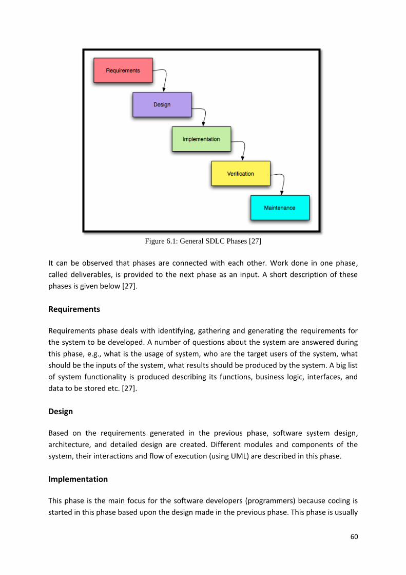
60
Figure 6.1: General SDLC Phases [27]
It can be observed that phases are connected with each other. Work done in one phase,
called deliverables, is provided to the next phase as an input. A short description of these
phases is given below [27].
Requirements
Requirements phase deals with identifying, gathering and generating the requirements for
the system to be developed. A number of questions about the system are answered during
this phase, e.g., what is the usage of system, who are the target users of the system, what
should be the inputs of the system, what results should be produced by the system. A big list
of system functionality is produced describing its functions, business logic, interfaces, and
data to be stored etc. [27].
Design
Based on the requirements generated in the previous phase, software system design,
architecture, and detailed design are created. Different modules and components of the
system, their interactions and flow of execution (using UML) are described in this phase.
Implementation
This phase is the main focus for the software developers (programmers) because coding is
started in this phase based upon the design made in the previous phase. This phase is usually

61
the longest phase of the software lifecycle that is why it is sometimes overlapped with
design and testing phases. [27].
Testing
This phase tests the software generated in the implementation phase against the
requirements of the system by making sure that software is providing the desired
functionality and is working according to the requirements of the system [27].
Maintenance
After the system is deployed at customer side, it needs to be maintained for future updates,
new features, process or requirement changes from users, bug fixes, customer support. All
such things are done in the maintenance phase.
6.2 – Traditional SDLC Models Traditional lifecycle models are considered to be the Heavyweight methodologies of
developing software. These methodologies usually follow the sequential series of steps to
accomplish a project, as shown in Figure 6.1. These methodologies are highly structured, and
require defining and documenting the requirements at the start of a project. They need
detailed planning and project management decisions to be done at the beginning of the
project. There are a number of SDLC models which follow this approach but we discussed
only the following:
Waterfall Model
Incremental Model
V-Model
RUP
6.2.1 – Waterfall Model
Waterfall Model is one of the first sequential software development models, and probably
the most criticized model. The development process is represented as a sequence of steps
(phases) in which execution is seen as flowing progressively downwards (like a waterfall)
through different phases, as shown in Figure 6.2. This model was presented in 1970 in an
article by W. W. Royce. Royce didn’t use the word “waterfall” for this model, but due to its
structure it became known as Waterfall model. This model requires that one phase should
be entirely completed before the start of the next phase. This means that phases cannot
overlap in the waterfall model. Also, each phase is reviewed after it is finished to check that
if the project is working as planned and whether to move to the next phase or not.

62
Figure 6.2: Waterfall Model
+
The waterfall model requires all the requirements should be defined and fixed in the
requirements phase. This behavior makes it very rigid and costly if there’s a need of change
in requirements later in the development as sometimes it is hard to foresee all the
requirements in the start. As no working version is released until the system is completely
finished, no one knows how the system is working until it is released for testing [28].
Despite all the criticism, the waterfall model is very well suited for those domains where the
requirements are well known at the start of the project and are unlikely to change during the
development. Such projects are usually the ones which are outsourced overseas. This model
was extensively used for large government projects, especially by the US Department of
Defense (DoD) [29].
Pros:
The waterfall model is very simple, easy to understand and straight forward.
Rigidity of the model makes it easier to manage due to the defined deliverables and
review process of each phase.
Works well for projects where requirements are very well understood, have well
defined architecture and established user interface.
Depending upon the complexity and size of the project, different phases can be
addressed with more engineering effort as needed.
It implements one phase at a time. In case of well known requirements, the project
can progress quickly to the implementation phase.
+ http://www.cse.lehigh.edu/~glennb/oose/figs/pfleeger/waterfall.jpg, 03-03-2011
63
Due to the more time spent on requirements and design in the start, time and effort
is saved at the end by avoiding the changes in the requirements and design in the last
stages.
Lifecycle phases are in compliance with the project management activities which
results in more accurate and lower cost and schedule estimates.
More focus is put on the well documentation of the system, and this saved
knowledge can then be reused by other people as well.
Cons:
Scope modification after requirements and design phases can be killing for a project.
Absence of a working version of the software until the late stages of the lifecycle
makes it difficult to track the progress and success of the project during the lifecycle,
and problems in the earlier phases are then discovered in the later stages.
Problems are usually identified during the system testing after the system is almost
coded, particularly the performance related problems. Problem resolution is often
moved to the maintenance phase.
Absence of unit testing makes it hard to completely test the system [24].
It involves a lot of risks and uncertainties but handling the risks is not part of the
initial phases. Risks keep moving forward in the lifecycle which are required to be
taken care of during the implementation phase.
It may not be a suitable model for ongoing projects (products) and for the projects
where requirements are more likely to change during the lifecycle.
Requirements need to be fixed before system design and implementation starts, but
usually these two phases identify a number of requirement inconsistencies, missing
components, and unnecessary requirements.
System can lack some needed functionality which was not identified in the
requirements phase [27] [29].
Due to the problems in the Waterfall model and the intense criticism on it, an improvement
in Waterfall model was suggested in which each phase provides feedback to the previous
phase to incorporate any changes in the early stages. A more complex feedback is provided
by the Development phase to the Requirement phase, and by the Verification phase to the
Design phase to decide about any changes in the requirements or the design of the system.
Figure 6.3 shows such a Waterfall model with iterative feedback.

64
Figure 6.3: Waterfall Model with Iterative Feedback [31]
6.2.2 – Incremental Model
The incremental model was an attempt to improve the waterfall model and to address the
issues highlighted in it. The whole lifecycle model is divided into a number of smaller and
easily managed iterations/cycles, and each of these cycles incorporates requirements,
design, implementation, and testing phases; which makes it a “multi-waterfall” lifecycle
model. Each of the iterations produces a working version of the software which is improved
in the subsequent iteration in the lifecycle [27]. This enables the users to see a partially
working system very early in the lifecycle and to reflect upon the changes for the subsequent
releases. Such a model is shown in Figure 6.4 below.
Figure 6.4: Incremental Development Model [24]
Like Waterfall model, most of the requirements are known at the beginning of the project.
These requirements are then grouped into iterations for incremental development in such a
way that the first iteration contains a core set of system functionality. After first iteration,

65
system with a core set of functionality is released where subsequent iterations keep adding
functionality to system until all requirements are met. Problem or new requirements
identified in one release can be incorporated in the next iteration. In this way, each
development cycle works as the maintenance phase for the previous release. This concept is
shown in Figure 6.5 below. Incremental model allows overlap in the development
cycles/iterations meaning that a subsequent cycle may start before the previous cycle is
finished [24].
Figure 6.5: Iterations in Incremental Development
+
Pros:
Incremental approach first focuses on the main features and then on the other
features if and when they are needed.
Helps in avoiding the ‘Big Bang’ effect, i.e. nothing happening for a long time, and
then suddenly, there is something new available [30].
Project can be stopped after any release, leaving a working product.
Requirements usually remain stable during an iteration but modifying and adding
new requirements in the next iterations is allowed. This means understanding of
requirements increases with each increment.
Testing becomes easier and more focused on each iteration, also provides a way to
continuously testing the system through integration testing after each iteration [31].
Each iteration provides feedback to the previous iteration which helps the team to
get “lessons learned” and improve the process continuously. This makes it more
responsive to the user needs than the waterfall model.
Risk management is better in this lifecycle model as risk is spread out over several
iteration, meaning risky parts are identified, monitored and handled in each iteration
separately [31].
+ From lecture notes of course Software Engineering, by David Broman

66
Project management is relatively easier as workload is spread over time, fewer
resources are needed, more flexibility in terms of changing scope and requirements,
and most importantly return on investments (ROI) can be seen earlier in the project.
Cons:
Like Waterfall model, phases inside iteration are rigid and cannot overlap each other.
The majority of the requirements should be known in the beginning otherwise it may
be problematic for the system architecture to incorporate the whole system, and it
can be difficult to map the requirements to the iteration [27].
It is not always recommended to incorporate requirements changes as it is costly to
go back and redesign an already implemented and tested release [29].
It is more difficult to perform formal reviews on a partially completed system than on
a complete system.
Development in multiple iterations requires well-defined interfaces between the
modules from the start.
It can be problematic with fixed-price contracts because a cost and schedule overrun
can result in an unfinished system.
Users have to learn the new system after each increment is deployed, which can
affect the daily and overall operations of the system [24].
Statistically less software.
6.2.3 – V – Model
V-model is another life cycle model influenced by Waterfall model in which processes follow
a sequential path of execution. This means that each phase must be finished before the next
phase starts. But there exists a major difference between these two models that testing is
much more focused throughout the development life cycle in V-model than in Waterfall
model. The reason this model is called V-model is that testing plans and procedures are
made for all the phases preceding and including implementation/coding phase. These
testing plans and procedures are then executed after the coding is done to verify those
phases which precede implementation phase [29]. Figure 6.6 below shows how these phases
form a V shaped model.

67
Figure 6.6: V–Model+
It can be seen from the figure above that each phase on the left-side of the model has a
corresponding testing phase on the right-side. Like waterfall model, Requirements is the first
phase of this model as well. During this phase an Acceptance test plan is created which
focuses on meeting the requirements of the system. The system architecture and design is
created in Design phase and a corresponding System Integration test plan is developed.
Module design phase is a low-level design phase where actual software components and
units are designed, and test plans are created for those units and components.
Implementation phase performs all the coding after which right-side phases of the V-model
executes all the test plans which were created earlier [27].
V-model incorporates project management activities, software quality assurance (SQA),
configuration management, and supporting tools throughout the development life cycle of
the software [12].
Pros:
Simple and easy to understand and use, and each phase generates some specific
deliverable.
Most suitable for projects which have better initial understanding of the
requirements, and where testing is more emphasized.
+ From lecture notes of course Software Engineering, by David Broman
68
Success rate is higher as compared to waterfall model due to the early development
of test plans, extensive testing of each phase, and more bugs catch ratio for each
phase [27] [29].
System is well documented.
Cons:
Very rigid and offers very little flexibility in terms of scope adjustment.
Requirements should be known in the start of the project as it is very expensive to
change or add requirements later during the life cycle as all the phases on left-side of
the model and their corresponding test plans are needed to be changed.
No working version of the software is released until the coding is finished.
Almost no involvement of the stakeholders [27].
More bugs are caught using V-model than waterfall model during development, but
they are very expensive to fix in the final product.
Total time taken by all the phases in the V-model exceeds the total time taken by the
Waterfall model [29].
6.2.4 – Rational Unified Process (RUP) Model
The Rational Unified Process (RUP) is a process framework to develop software iteratively
and incrementally, especially the object-oriented software systems as it complements UML
(Unified Modeling Language). It is not a distinct and fixed way of working; rather it is an
adaptable process framework which organizations can tailor according to their development
process needs. It is based on some basic building block which describes: what to do, how to
do and who can do it. These basic building blocks are Work Products (what deliverables are
required), Tasks (how to do things) and Roles (who possess the required skills and
competencies) [32].
As RUP is an adaptable process framework, a lot of tool support, inter/intra-net resources
and different kinds of document templates are provided with it. RUP has a two dimensional
process structure which is shown in Figure 6.7. This two dimensional structure does not only
require most of the requirements gathering initially but emphasizes stakeholders
involvement through use-cases and multiple sub-releases. This makes RUP somewhat
intermediate between document/plan-driven (traditional) and agile methods (discussed in
the next section) [30]. RUP’s process structure is briefly explained below.

69
Figure 6.7: RUP’s Two Dimensional Model
+
RUP Dimensions
RUP is structured into two dimensions: Phase dimension and Discipline dimension. Each
phase can further be divided into several iterations. Discipline dimension includes six
Engineering disciplines (Business Modeling, Requirements, Analysis and Design,
Implementation, Test, and Deployment) and three Supporting disciplines (Configuration and
Change Management, Project Management, and Environment). Figure 7.7 shows the degree
of attention and emphasis that each discipline gets in different phases. A brief description of
each phase is given below [33]:
Inception
Project scope and business case is formulated. A feasibility study is done to decide to
start with the project or not. Most important requirements are gathered which help
defining scope of the design of the software. Initial project plan, resource plan and
risk management plans are made here.
Elaboration
Now things are done in more details, e.g., system architecture, SRS, architectural
prototype if needed, project management plan, risk analysis and management plans.
Construction
Previously made plans are executed to implement the design through coding. Several
beta releases are developed in a number of iterations. These releases are tested and
deployed at customer side for further testing by them. All the necessary and required
+ http://www.ibm.com/developerworks/rational/library/apr07/santos/index.html, 15-03-2011

70
documentation is prepared. At the end of the phase a working system sufficient
enough to be tested by the user under realistic settings is ready.
Transition
Tested system is deployed at user-side for beta-testing. Stakeholders agree upon if
the objectives defined in Inception phase are satisfied. Training is provided both to
the users and maintainers. By the end of this phase, product is working in the
operational environment.
Figure 6.8 shows the percentage of work done during different phases in RUP. It depicts that
each phase can have several internal iterations and each iteration can have internal
milestones and releases.
Figure 6.8: RUP Workload Percentage
+
RUP’s Six Best Practices
RUP describes six best practices which are considered as a role model in software
engineering while designing a project with minimum faults and increased productivity. These
practices are [32]:
Develop Iteratively – Increases stakeholders’ involvement and feedback.
Manage Requirements – Satisfy both internal and external stakeholders.
Use Components – Break down into modules and components, employ object-
oriented programming and code reuse.
Model Visually – Encouraged use of UML (Unified Modeling Language).
Verify Quality – Testing throughout the project should be a major focus.
Control Changes – Continuously control, synchronize and verify changes in the
modules developed by different developers/teams.
Pros:
RUP is a complete methodology with a focus on precise documentation. Its use-case
driven approach enables expressing the user perspective in a easy and natural
+ From lecture notes of course Software Engineering, by David Broman
71
language, increases traceability, helps in defining test-cases and planning the
iterations.
Its iterative approach makes it proactive in handling risks early in the project, and the
risks related to requirements changes through careful change request management.
Iterative approach also enables reuse and lessons learned from previous iterations.
Reuse of components shortens the total time required for development. Total
integration time decreases at the end as integration is done throughout the project
life cycle.
It does not only describe software development processes but covers project
management and control activities as well.
It provides a number of tools and documents which are easy to learn and use, as well
as provides online training and support for its processes [34].
Cons:
Requires expert and specialized skills in the team to work with its tools.
Size of the whole model with all its documents, tools is too big, and the development
process is too complex and disorganized.
It is too generic with less implementation details and needs to be customized before
using it (but this can be considered as a Pro as well).
Reuse is not possible all the time, especially for advanced projects which use
advanced technology.
Continuous integration throughout the lifecycle can cause confusions and testing
related issues in case of big projects with multiple development streams.
Tools required for RUP are extremely expensive and requires training which is very
expensive and time consuming which may not be very cost-effective for mid-size to
small projects.
But the most common issue is its complexity and tool training for novice users
[34].
6.3 – Agile Methods All the methodologies described in the previous section assume that software development
process is predictable and repeatable. One criticism is their extra focus on following the
procedures and making documentation; another criticism is their extensive emphasize on
structure [28]. This makes them heavyweight methodologies because changing the direction
becomes really difficult after the contract has been signed and team starts working. But if
the reality changes then it needs a lot of rework to fit into the architecture, delays the
schedule, and becomes like changing the direction of a train [30]. As a result, a number of
lightweight methodologies started to emerge in mid 90’s arguing that software development
was a human activity so there would always be variations which should be considered in a
flexible enough model otherwise a lot of effort would be waste. These methodologies were
based on the ideas such as self-organizing teams, face-to-face communication, less

72
documentation and more frequent releases. Eventually, creators of these methodologies,
including Kent Beck, Martin Fowler, and Ward Cunningham, decided to form an alliance
which was named the Agile Alliance. They published an Agile Manifesto and principles of
agile software development which are stated below [35].
Agile methodologies consider the fact that world is a chaotic place where change is
inevitable. They focus on delivering the value to the customer as soon as possible instead of
consuming time on making extensive plans, procedures and documents which won’t be used
completely anyways [30]. They promote the principle of “Build Short, Build Often” by
breaking the project into iterations which are usually 3-4 weeks long [28].
Agile Manifesto and Principles
Agile Alliance has published an Agile Manifesto and twelve principles which are given below:
Individuals and interactions over Processes and tools
Working software over Comprehensive documentation
Customer collaboration over Contract negotiation
Responding to change over Following a plan
Table 6.1: Agile Manifesto [2]
That is, while there is value in the items on the right; we value the items on the left more [2].
Agile software development is based on the following twelve principles, shown in Figure 6.9:
Figure 6.9: Agile Principles [36]

73
Several Agile software development methodologies have been introduced and some of them
are being used widely. But we introduced briefly only these three more popular agile
methodologies in the next sections:
Extreme Programming (XP)
Scrum
Lean
6.3.1 – Extreme Programming (XP)
According to its creator Kent Beck [49], “XP is a lightweight, efficient, low-risk, flexible,
predictable, scientific, and fun way to develop software.” It is such a software development
methodology in which the full-time focus is on the customer and on the iterative delivery of
high quality software. According to XP advocates, change in requirements during the
development is a natural part; therefore rather than fixing the requirements at the start, XP
keeps adapting to the changing requirements throughout the development of the software.
This is only possible through a close working relationship between the development team
and the customers. The XP lifecycle is a series of iterations. Each iteration contains tasks like
feature Definition, Estimation, feature Selection, and feature Development, as shown in
Figure 6.10. At the start of each iteration, customer tells the required features of the
software to the developer. Developer in turn makes work estimates for those features and
gives estimation to customer. Customer then prioritizes/chooses the features to be
implemented first or during this iteration. Developer then starts developing those chosen
features, and after finishing the development the same steps are repeated for the next
iteration. After completing each iteration, XP teams become more efficient with more
features delivered and more changes accepted [35].
Figure 6.10: XP Iterative Process Model [35]
Some of the features that make it unique from other methodologies are:
Continuous feedback after each cycle.
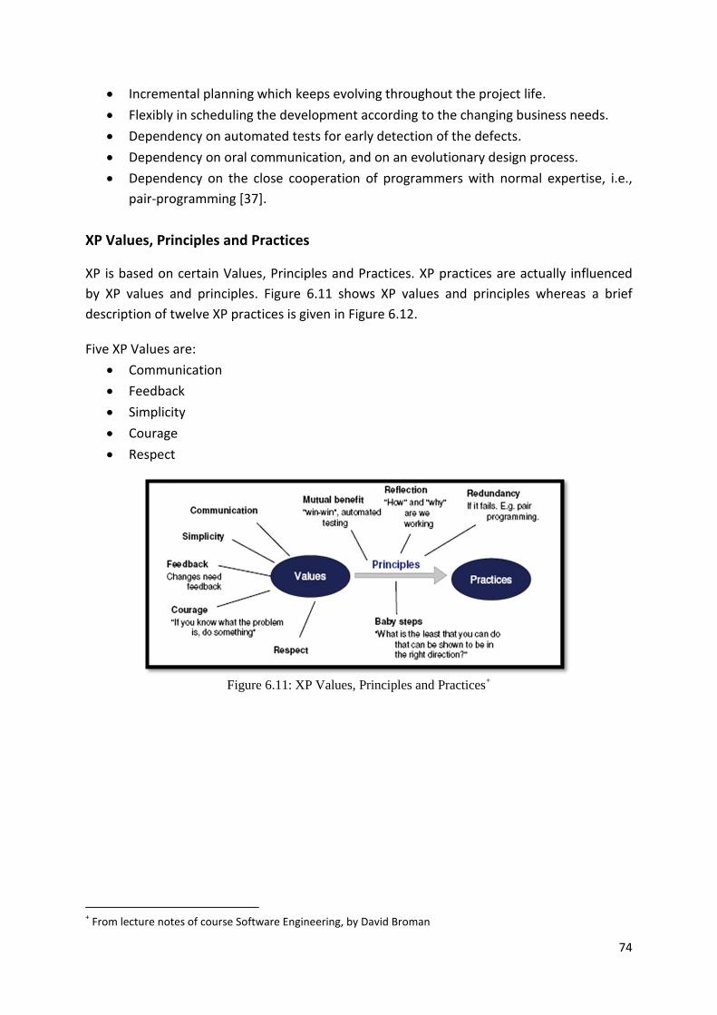
74
Incremental planning which keeps evolving throughout the project life.
Flexibly in scheduling the development according to the changing business needs.
Dependency on automated tests for early detection of the defects.
Dependency on oral communication, and on an evolutionary design process.
Dependency on the close cooperation of programmers with normal expertise, i.e.,
pair-programming [37].
XP Values, Principles and Practices
XP is based on certain Values, Principles and Practices. XP practices are actually influenced
by XP values and principles. Figure 6.11 shows XP values and principles whereas a brief
description of twelve XP practices is given in Figure 6.12.
Five XP Values are:
Communication
Feedback
Simplicity
Courage
Respect
Figure 6.11: XP Values, Principles and Practices
+
+ From lecture notes of course Software Engineering, by David Broman

75
Figure 6.12: XP Practices [37]
Two additional useful practices were suggested later which were not part of the initial
model:
Dialy Stand-up meetings
Retrospectives
Roles and Responsibilities
XP defines the following roles in the model:
Programmer
Customer
Tester
Tracker
Coach
Consultant
Manager
Pros:

76
Lightweight methodology suitable for small to medium sized projects.
Establishes a good team working environment especially when developers are not
willing to adopt a fixed software process, enabling them to manage themselves
better.
Focus on the quality of the final product through test based requirements,
continuous testing and integration and quality assurance.
Focus on customers and frequent feedback helps in meeting the needs of the users.
Incremental and frequent releases through iterative development helps in decreasing
the risk, i.e., after each iteration team gets to know if the approach is working, and
increased involvement and feedback from customer confirms if the work is going in
right direction [38] [39].
Cons:
Not preferable for large scale projects where documentation is required; lack of
documentation can be problematic when a programmer leaves and new comes in
[38] [39].
Requires specialized skills and experience, and a lot of cultural change [38].
Programming in pairs can be very costly, especially when programmers are not
willing to work together, or are not willing to share their code; will not work if
programmers are at separate geographical locations.
Lack of detailed requirements and scope documentation can make it very inefficient
especially when the requirements are changing a lot and the same part is
reprogrammed several times.
Code-centric approach rather than a design-centric approach; can start working with
an insufficient specification and design [40].
One of the main disadvantages is its dependability upon continuous customer
involvement with development team. Customers might not be available always, or it
can be very expensive for them to have frequent meetings, or they might dislike it
[39].
Contract negotiation can be very tricky as the realistic estimates are very hard to
make because the entire scope/requirements of the project are not known in the
start.
Difficult to convert non-functional quality attributes into user stories [40].
6.3.2 – SCRUM
Scrum is one of the most popular and perhaps best known Agile methodologies these days.
Scrum is not only a methodology in itself but also a framework of defined practices and roles
to follow during the lifecycle of a project. Like other Agile methods, scrum also supports
short iterations with small and self-organized teams implementing well defined tasks. [35].
Scrum is based on the principle that the change in requirements or requirements churn
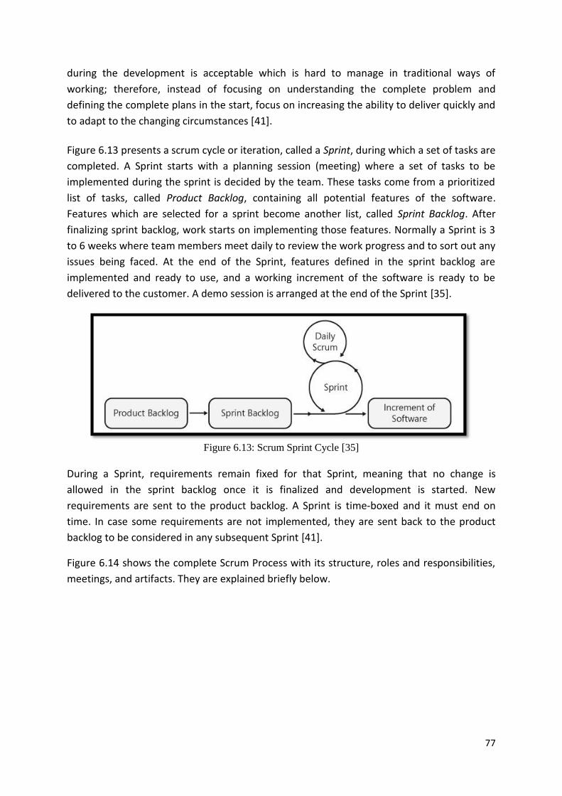
77
during the development is acceptable which is hard to manage in traditional ways of
working; therefore, instead of focusing on understanding the complete problem and
defining the complete plans in the start, focus on increasing the ability to deliver quickly and
to adapt to the changing circumstances [41].
Figure 6.13 presents a scrum cycle or iteration, called a Sprint, during which a set of tasks are
completed. A Sprint starts with a planning session (meeting) where a set of tasks to be
implemented during the sprint is decided by the team. These tasks come from a prioritized
list of tasks, called Product Backlog, containing all potential features of the software.
Features which are selected for a sprint become another list, called Sprint Backlog. After
finalizing sprint backlog, work starts on implementing those features. Normally a Sprint is 3
to 6 weeks where team members meet daily to review the work progress and to sort out any
issues being faced. At the end of the Sprint, features defined in the sprint backlog are
implemented and ready to use, and a working increment of the software is ready to be
delivered to the customer. A demo session is arranged at the end of the Sprint [35].
Figure 6.13: Scrum Sprint Cycle [35]
During a Sprint, requirements remain fixed for that Sprint, meaning that no change is
allowed in the sprint backlog once it is finalized and development is started. New
requirements are sent to the product backlog. A Sprint is time-boxed and it must end on
time. In case some requirements are not implemented, they are sent back to the product
backlog to be considered in any subsequent Sprint [41].
Figure 6.14 shows the complete Scrum Process with its structure, roles and responsibilities,
meetings, and artifacts. They are explained briefly below.

78
Figure 6.14: Scrum Complete Methodology
+
Core Scrum roles
Scrum includes the following core roles and responsibilities during the sprints and throughout the project.
Product Owner
The product owner is the communication channel between the Customer and the
Team, and makes sure that the Team is adding value to the business. The Product
Owner is responsible for creating the product backlog by writing user-stories,
prioritizing them and putting them in the product backlog. There should be only one
product owner for the scrum team(s) and should not be the same person as Scrum
Master.
Scrum Master
Each Scrum Team has a Scrum Master whose main responsibility is to address
challenges, resolve any issues and remove any hurdles which are coming in the way
of the Team to reach their sprint goals/deliverables. Some other responsibilities of
the Scrum Master include enforcing the rules inside the Team, and to protect the
Team from any external disturbance to let them focus on the work at hand.
Team
A Scrum Team normally consists of 5–9 persons who are responsible for developing
and delivering the product. The Team contains members with multi-functional skills
who perform a number of tasks including analysis, design, development, testing,
technical communication, documentation. the Team is self-organized and usually + http://www.scrumforteamsystem.com/ProcessGuidanceOld/v2/Scrum/Scrum.aspx, 25-03-2011
79
follows some kind of team management methodology to organize themselves
internally [41].
Scrum Meetings
A number of meetings are arranged throughout the project lifecycle, including:
Sprint Planning Meeting
A Sprint Planning Meeting is held before the start of every sprint cycle. During this
meeting the product backlog is reviewed about any changes or new priorities, and
based upon that tasks are selected which needs to be done during the next sprint. A
sprint backlog is prepared and prioritized with effort and time estimation of each
task. These tasks are then compared with the available resources in the team to
identify how much work can be done during the sprint. This meeting is typically 8
hours long; during 1st four hours Product Owner and the Team discuss the product
backlog and its priorities to select the tasks, during the 2nd four hours only the Team
prepares sprint backlog and a plan for the sprint.
Daily Scrum
After starting the sprint, a 15 minutes long meeting is held every day, called Daily
Scrum or Daily Standup, during which each team member tells about what they have
done yesterday, what they are going to do today, and if there are any problems they
are facing. The Scrum Master should take up the resolution of any problems being
faced after this meeting.
Sprint Review Meeting
This meeting is held at the end of a sprint cycle and is typically 4 hours long. During
this meeting the completed work is presented to the related stakeholders (a.k.a. “the
demo”), and the completed and uncompleted tasks are reviewed.
Sprint Retrospective
This meeting is held at the end of the sprint, after the Sprint Review Meeting. This
meeting is typically 3 hours long during which all the Team members reflect about
the previous sprint and make suggestion about improving the next sprint, can be
considered as “continuous process improvement” [41].
Scrum Artifacts
Product Backlog
The Product Backlog is list of all potential features which need to be implemented in
the product. A rough estimate of the business value as well as development effort of
each feature is also given in the list. Anyone can view and edit this list but it is the
responsibility to maintain and prioritize this list.
Sprint Backlog

80
The Sprint Backlog contains the features that need to be implemented during the
sprint. These features are further divided into tasks. Each task should be 4–16 hours
of effort. These tasks are not assigned to the team members; rather anyone can
select a task according to task priority and their skill level. A Task Board is used to
track the progress of each task in the sprint. This task board groups tasks according to
their stat, for example To Do, In Process, To Verify, and Done, as shown in Figure
6.15.
Figure 6.15: Sprint Task Board
+
Impediments List
It is a list of all possible problems which can disturb or stop the team members to
perform their tasks as efficiently as possible [41].
Burn Down Chart
The Burn Chart helps in viewing the progress of the team against the estimated and
remaining time. There can be both Product Backlog Burndown Chart and Sprint
Backlog Burndown Chart. It shows that how many hours have been spent since the
start of the sprint and how many hours left until the end of sprint to finish the
remaining work [41]. Such a burn down chart is shown in Figure 6.16.
+ http://www.mountaingoatsoftware.com/scrum/task-boards, 01-04-2011

81
Figure 6.16: Sprint Burn-Down Chart
+
6.3.3 – Lean Software Development
Lean Software Development methodology can be regarded as another development method
movement that was started to solve the issues and problems of old and traditional
development methodologies, for example Waterfall. Lean methodology is originated from
Toyota Production System and it attempts to optimize an organization’s production
processes to enable them to deliver products to the market quickly and with a higher
quality. Its main focus is on the people who develop the products and on their efficient
communication which can enable them to deliver good quality products that satisfy the
customers [42].
Lean methodology is based upon five principles and a number of practices which are
influenced by the Toyota Production System. These principles are abstract in nature which
makes it possible to apply them to other business domains as well than car manufacturing.
According to the authors of the book Lean Thinking, James Womack and Daniel Jones [43],
these five core principles are:
“Specify value from the standpoint of the end customer by product family.
Identify all the steps in the value stream for each product family, eliminating every
step and every action and every practice that does not create value.
Make the remaining value-creating steps occur in a tight and integrated sequence so
the product will flow smoothly toward the customer.
As flow is introduced, let customers pull value from the next upstream activity.
As these steps lead to greater transparency, enabling managers and teams to
eliminate further waste, pursue perfection through continuous improvement” [43].
+ http://www.didiergeorges.com/blog/presentation-de-scrum, 10-04-2011

82
Lean Principles for Software Development
As developing the software is totally different from assembling cars, these lean principles
need some interpretation to make them applicable to software development. Mary and Tom
Poppendieck have published a series of books, named Lean Software Development [44], in
which they have provided a detailed mapping of the Lean principles to the software
development making them more understandable through these following principles [42]:
1. Eliminate Waste
All those things which do not add any value for the customers are waste. Only
focus on the things which create value for the customer. Write less code and not
only focus on being innovative but also understand what contains more value for
customer. Seven wastes of software development are listed in Table 6.2:
Seven Wastes of
Manufacturing
Seven Wastes of Software
Development
Inventory Partially Done Work
Extra Processing Paperwork
Overproduction Extra Features
Transportation Building the Wrong Thing
Waiting Waiting for Information / delays
Motion Task Switching / Interruptions
Defects Defects
(Additional eighth waste)
Underutilization of people
Underutilization of people’s
creativity and resourcefulness
Table 6.2: Seven wastes in Lean Software Development [45]
2. Create Knowledge
Team’s knowledge should be recorded so that the problems which have already
been figured out are not worked upon again. Moreover, listen to your team
member and ask them smart questions, and try to record certain design decisions.
Create a culture where everyone can improve themselves because no one is
perfect and no one should be perfect – there must be something always to
improve. Team should be able to perform small researches, make hypothesis and
perform quick experiments to verify them.
3. Build Quality In
Make your code mistake-proof by writing test cases as soon as you start writing
code. Don’t wait for the bugs to be caught by the testers. (One of the most famous
principle of Toyota Production System that if a problem is detected, stop the whole
assembly line and focus on finding and solving the root cause of the problem so
that it never occurs again). Try to automate all those manual works which can be
83
automated without creating any problems to the development, e.g., automate
testing, builds and installation processes. Refactor as much as possible the code,
tests and documentation to make duplication ZERO and to minimize the
complexity.
4. Defer Commitment
You should not be very quick about making decisions, consider multiple solutions
to the critical decisions and compare and select the best one. “The best decisions
are made when you have the most information available – but don’t wait too long”
[45].
5. Optimize the Whole
Do not only focus on the software development but consider the whole Value
Stream while optimizing. Delivery of a high quality final product is only possible
through the team-work of engineers, sales and marketing specialists, secretaries.
6. Deliver Fast
Try to work in small increments with shorter release time to deliver more often.
Try to repeat the good things after every cycle and remove/correct the practices
which create problems. Don’t fill work queue with big tasks which will block other
tasks; rather divide tasks into sub-tasks and try to utilize the cycle time efficiently.
Most importantly, value the customer feedback the most which can help in
reducing a lot of waste and rework in subsequent cycles.
7. Respect People
Provide team leaders and supervisors some training and guidance and give them
some liberty to implement lean practices in their own way. Try to involve lower
team members at lower level in thinking and decision making process, and
encourage them to identify problems in the current practices [42].
Lean Software Practices
Lean software development comes with a pile of software development practices from
which an organization can choose what to (and not to use) and when to use. Some of these
practices are same as those in Agile methodologies, still some practices are expressed
slightly different. Some of these Lean practices are listed below [45]:
Source Code Management and Scripted Builds
Implement a Configuration Management System (CMS) to maintain all the source
code, test cases and documentation. It should be possible to make the software build
through a script or a single command.
Automated Testing
Implement Test-Driven Development (TDD) / Test-First Development (TFD). Try to
perform all these tests: Unit Tests (with mocks and stubs), Integration Tests, User
84
Interface Tests, Non-functional Tests (Performance, Load, Security, Compatibility, and
Usability Tests)
Continuous Integration (CI)
Continuous integration helps in debugging, gives quick feedback, reduces the big
integration effort at the end, and provides a snapshot of the current state of the
project. To implement continuous integration, these things need to be available all
the time: a CMS, Framework for unit testing, script for automated build, build server,
and continuous integrations software.
Less Code
Refactor code and design as much as possible to make zero duplication. And try to
write less code on the first hand by implementing good practices, such as: code only
the tasks of current iteration, write code as simple as possible, reuse existing code,
and encourage of the use of design patterns, coding standards and best practices.
Short Iterations
Work in short iterations and follow the iteration’s timeline. Work on prioritizes
requirements and deliver each iteration’s work to the customer with a demo. Short
iterations increase feedback which helps in making course correction by removing
any initial misunderstandings or any change in requirements.
Customer Participation
It is very important to involve the customer during the development process by
asking them to write requirements and acceptance tests, keeping them informed
about the project status and continuously asking for their feedback. It is very
important to have a CRACK (Collaborative, Representative, Authorized, Committed,
and Knowledgeable) customer representative in the development team [45].
Lean Vs. Agile
The goal of both Lean and Agile software development methodologies is to increase the
quality of the software as well improve the development processes. Both welcome and
incorporate change and value most the delivery of such software that fulfills customer’s real
needs, not the initially identified needs or initial customer desires.
Although there are a lot of commonalities between Lean and Agile methodologies, but there
exists a very basic difference between their fundamental point-of-view, philosophy and
scope.
Agile is more concerned with the particular practices of producing the software and
managing the software development projects, usually not concerning about the whole
business context of the organization in which software development is taking place. Lean
principles, in contrast, are applicable to any scope covering from the specific development of
a software project to the whole organization where software development is just a small

85
part. It can even extend the scope to include external suppliers. “The larger the scope, the
larger the potential benefits” [45].
Figure 6.17 shows the scope of Lean and other Agile methodologies. It does not mean, at all,
that XP is a subset of Scrum, or that Agile is a subset of Lean. It tries to explain that Lean
principles are applicable to a very wide and any context, XP’s scope is limited to only
software development domain, whereas Scrum lies somewhere in between.
Figure 6.17: Scope of Lean Software Development+
+ http://blog.crisp.se/henrikkniberg/2008/10/19/1224451800000.html, 28-04-2011
86
6.4 – Agile and SPICE As explained earlier, Agile approaches, such as eXtreme Programming (XP) and Scrum, are
considered the solution to the problems of traditional software development, such as, long
time to delivery, high cost, quality related issues. Although, Agile approaches have proven
better for some companies, but some still argue that plan-driven methods are preferable for
safety-critical and high risk systems. This divides software community into two schools of
thoughts: the agilers and the orthodox. However, these plan-driven and agile approaches
can exist side by side, and a better approach is to combine suitable agile practices with
company’s current plan-driven approaches to get benefit out of both. SPICE model, at the
same time, is regarded as a plan-driven, formal and document-based approach to Software
Process Improvement (SPI) and is hardly combined with the Agile practices in such Agile
organizations. However, SPICE model, if effectively applied in these organizations, can create
a very good synergy of software engineering and management practices [46].
Misconceptions about SPICE
There exist a number of misconceptions about SPICE model due to which organizations avoid
following it. Some of these misconceptions and explanation to them are given below.
One of the most common misconceptions is that the organization needs to follow V-
model in order to apply SPICE standards. This is not true; SPICE does not require any
specific life cycle model to be followed. Although, the processes included in the SPICE
process reference model (PRM) are taken from ISO/IEC 12207 and match processes
of V-model, but their sequence and importance level is not decided in the standard.
It is totally up to the organization to select the processes according to their business
needs and goals and make their own PRM, as explained in Chapter 3.
Another misconception is that SPICE requires performing predefined Base Practices
in order to achieve Capability Level 1. This is not true completely; what Capability
Level 1 requires is the achievement of Process Outcomes through producing Work
Products. Any practices can be used to produce these work products.
Some other misconceptions include production of a number of heavy documents,
including a detailed project plan, reports, design documents, etc. This is true to some
extent as SPICE requires producing a formal project plan, but it does not set the level
of detail or formalism of the project plan. It is totally up to the organization and the
project to choose any level of formalism of the document. Furthermore, it only
requires producing those documents which are necessary for the project as well as
for the organization’s business goals. To reach Capability Level 2, it requires having
processes and activities already planned and well managed.
Another misconception is that SPICE requires having a defined set of process to be
followed by all the projects. This is not true completely. SPICE only requires at
Capability Level 3 to have a set of standard and generic processes which should be

87
tailored and adapted according to the specific project’s needs. This does not mean at
all to replicate those standard processes in all projects [47].
Agile and SPICE Capability Levels
This section analyzes the applicability of SPICE model to Agile organizations. Agile is
discussed here from a generic point of view and no specific Agile method is referred to. Five
Capability levels of SPICE process assessment model (PAM) are considered here to see if they
can co-exist within Agile organizations.
Level 1: At capability level 1, processes have achieved their purpose. This means that
processes have produced outcomes using some techniques, method or tools. Now
the question is whether Agile practices can achieve the same process purposes as
traditional approaches do. The point to understand is that most of the Agile practices
have come from traditional approaches but applied in a manner and intensity (e.g.,
release frequency, direct communication, short-term planning). Furthermore, a
number of organizations which follow SPICE model are applying iterative software
development model successfully, for example AE (discussed in the next Chapter).
Level 2: Capability level 2 requires that processes are planned and monitored, and
work products are established and maintained properly. Capability level 2 requires
adjusting the performance of the processes and assign proper resources to achieve
the process objectives. Moreover, work products must be managed, reviewed and
adjusted to meet the defined requirements. This shows that SPICE allows changes
and adjustments in the initial plans when needed. This fits well with the Agile
approaches which tend to focus on answering questions rather than following long-
term plans.
Level 3: This level requires having a Defined set of standard/generic processes in the
organization and all the projects should use these processes by tailoring and
adjusting them according to the specific project needs. This aspect fit well with Agile
practices as Agile processes are flexible and adaptable enough to respond to the
changing circumstances effectively. This means Agile organizations can tailor their
already implemented processes to fit to the other projects context as well.
Level 4: At this level, processes must be measured to make sure that process
objectives are met and business goals are achieved. SPICE does not identify which
measures should be collected and used. In Agile methodologies, working software is
the main measure of progress in the project, meaning that “number of user-stories
implemented” is regarded as the main measure to determine the level of progress
and achievement of objectives. Another requirement at capability level 4 is to use the
measurement results to adjust the performance of the processes. This is very much
acceptable in Agile methodologies.
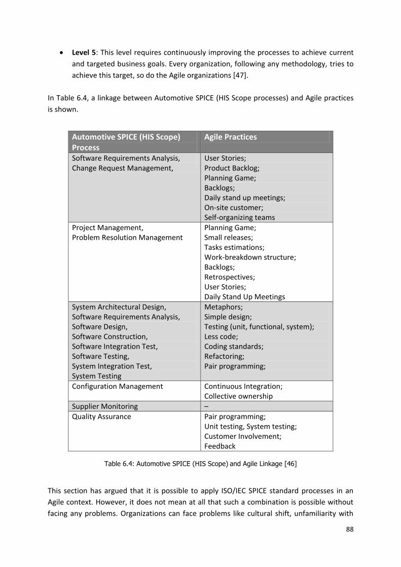
88
Level 5: This level requires continuously improving the processes to achieve current
and targeted business goals. Every organization, following any methodology, tries to
achieve this target, so do the Agile organizations [47].
In Table 6.4, a linkage between Automotive SPICE (HIS Scope processes) and Agile practices
is shown.
Automotive SPICE (HIS Scope) Process
Agile Practices
Software Requirements Analysis, Change Request Management,
User Stories; Product Backlog; Planning Game; Backlogs; Daily stand up meetings; On-site customer; Self-organizing teams
Project Management, Problem Resolution Management
Planning Game; Small releases; Tasks estimations; Work-breakdown structure; Backlogs; Retrospectives; User Stories; Daily Stand Up Meetings
System Architectural Design, Software Requirements Analysis, Software Design, Software Construction, Software Integration Test, Software Testing, System Integration Test, System Testing
Metaphors; Simple design; Testing (unit, functional, system); Less code; Coding standards; Refactoring; Pair programming;
Configuration Management Continuous Integration; Collective ownership
Supplier Monitoring –
Quality Assurance Pair programming; Unit testing, System testing; Customer Involvement; Feedback
Table 6.4: Automotive SPICE (HIS Scope) and Agile Linkage [46]
This section has argued that it is possible to apply ISO/IEC SPICE standard processes in an
Agile context. However, it does not mean at all that such a combination is possible without
facing any problems. Organizations can face problems like cultural shift, unfamiliarity with

89
the new practices, project scope, and risks involved. But this should not stop organizations
to get their process maturity assessed by SPICE model and to make improvements in those
processes accordingly [47]. This can incur a number of benefits for organizations, such as
they can be more structured in the way of their working and at the same time flexible for
accepting any change both in project scope and in processes, they can standardize their own
Agile practices to produce required outputs, they can improve their planning and
documentation levels, and can introduce a number of useful metrics and measurements
techniques.
6.5 – Summary and Comparison
The Agile and heavyweight methodologies both have their strengths and weaknesses, as
discussed in the previous sections. Organizations usually follow either one of these
methodologies or follow their own customized methodology which can be a hybrid of more
than one methodology. There are several major factors affecting methodology decision and
selecting which is suitable for various conditions. These factors can be categorized into
project size, people, risk etc [33]. Also, by combining Agile and standard process models like
ISO SPICE, organizations can get the best out of these in terms of cost, quality and time-to-
market.
The following Table 6.3 gives a summary and a comparison between Traditional and Agile
software development methodologies.
Characteristic Traditional Agile
Approach Predictive Adaptive
Project Size Large Small to medium
Stages Requirements, Design, Code,
Test, Feedback phases follow
each other in this order
Requirements, Design, Code,
Test, Feedback phases are
parallel and iterative and can
influence each other
Requirements Fixed requirements;
documented in details from the
start of project
Evolving requirements;
documented briefly
Time & People Varies in different stages; usually
works with and manages large
teams
Works with small and fixed
teams and time; does not
encourages large teams
Planning Creates detailed planning
documents, e.g., Gantt Chart
Short term plans for each
iteration, based on based on

90
and follow them throughout the
project
Tasks/Features to be
implemented
Team Composition Defined and specialized roles
and skills for team (Analyst,
Designer, Developer, Tester)
Team with general skills; anyone
can be assigned any role
Monitoring Against the Plan Against the Task/Feature List
that needs to be implemented
Management Style Command and Control Leadership-Collaboration
Customer Involvement Mostly Before and After; Only if
needed during the development;
Throughout the project; mostly
an on-site customer available
Negotiable Estimates Schedule
Testing Mostly after code is finished Concurent with coding
Feedback During testing phase, and after
delivering to the customer
Frequent, after each iteration
delivery
Managing Change Avoid changes in the planned
tasks
Show flexibility to accept
change
Knowledge Transfer Detailed documentation;
knowledge-repository
Effective verbal communication;
understandable source code
Process Improvement Through implementing metrics;
Process-oriented
Through the people involved;
People-oriented
Success Achieving the predicted cost and
schedule estimations
Quality and delivered value of
the working software
Return on Investment (ROI)
At the end of project Early in the project
Risk Well understood risks from the start; Minor impact at the end
Unknown risks from the start; Major impact at the end
Suitability* Large, critical, reliable, and safe systems with well understood requirements
Small to medium sized projects with evolving requirements
Table 6.3: Comparison of Agile and Traditional Methodologies [48] [49] [50]
* Selection of any specific methodology depends upon several factors, and can vary in different
situations; therefore, above Suitability factor is not fixed and final.

91
Chapter 7 – Lifecycle Model at AE
This chapter presents a case study of integrating Agile practices into a traditional company-
tailored software development model at AE. Two different software teams which were
started at different points in time were interviewed. Their experiences were investigated
(regarding the combination of Agile practices with their traditional development model that
was also incorporating A-SPICE processes). Another point to note here that this case study
only focuses on the experiences related to the team management, planning tasks, calendar
time, scope and resource management activities, but does not include experiences related
to the actual software development activities.
7.1 – Development at AE
Automotive industry follows the parallel development of hardware, software and system;
and requires multiple release cycles for software. This multiple release strategy can be
described as “Release-Change Request-Update Release”. These multiple release cycles
become more complicated in automotive industry due to the parallel development cycles of
hardware ECUs. While selecting a software development life cycle methodology, therefore,
it becomes really important to consider this way of working in automotive industry. Software
development inside AE is not following any single specific life cycle model. Instead, software
development process model inside AE has evolved over time and is a hybrid approach of
more than one life cycle model. This model takes care of both multiple releases as well as
parallel development strategies. It delivers software to the system test team at regular
intervals (multiple releases) and synchronizes with other development parts such as ECU,
System, test (parallel development) for a coordinated delivery to the customer.
7.1.1 – Product Development Process Model
Software development process model is a part of AE’s larger Product Development Process
Model which covers the development as well as management of different areas including
system, hardware, software, mechanical and electronics. Processes in this model are
designed to be compliant with the processes given in Automotive SPICE’s process reference
model (PRM). Annex C shows a System Diagram containing hardware, software, mechanics
and their relationships, which all work together to develop a product. AE’s complete Product
Development Process Model is not discussed in details here as discussing the whole model is
out of scope of this report. This model includes the following processes and subprocesses
(please note that subprocesses of only System Eng. and Software Eng. are shown; others are
not included here):
Project Management
Supplier Monitoring
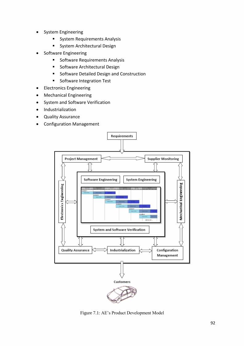
92
System Engineering
System Requirements Analysis
System Architectural Design
Software Engineering
Software Requirements Analysis
Software Architectural Design
Software Detailed Design and Construction
Software Integration Test
Electronics Engineering
Mechanical Engineering
System and Software Verification
Industrialization
Quality Assurance
Configuration Management
Figure 7.1: AE’s Product Development Model

93
7.1.2 – Project Teams Structure
Before going into details of the software development process model, it is very important to
understand how different teams are organized inside AE. There are several software projects
going on inside AE. Each project is developed by a different team. All the projects are
following a special team structure. Each project has a Project Leader who supervises four
sub-team leaders inside that project: System Design Team Leader, Hardware Team Leader,
Software Team Leader, and Testing Team Leader. These four leaders supervise their own
teams working under them. This means that each project consists of four teams. These sub-
teams inside a project communicate and deliver to each other internally as well as to the
teams in the other projects (as some projects are dependent on each other) and directly to
the customers as well in some cases. Figure 7.2 shows such a team structure.
Figure 7.2: Team Structure of a Project in AE
7.1.3 – Software Development Model
Because of projects team structure; parallel development of system/hardware/software;
and multiple releases of software, it becomes really important that the software
development life cycle model takes care of all these factors. AE has tailored a software
development approach based on the concepts of Incremental Development in which
software is developed in several Increments. Each Increment contains three phases or
activities: System Activity, Software Activity, and Test Activity. These Increments are time-
boxed and overlap each other, meaning that each increment has a fixed start- and end-date,
and next increment starts before the end of previous increment. Figure 7.3 shows this time-
boxed incremental development model.
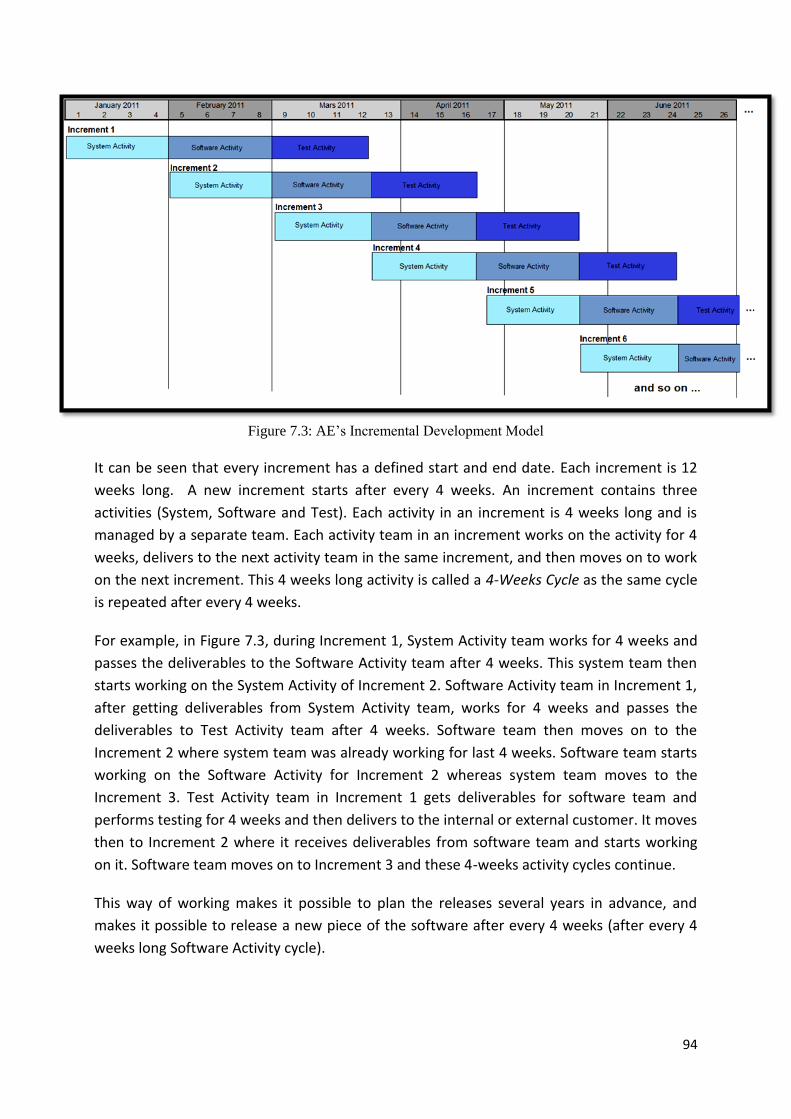
94
Figure 7.3: AE’s Incremental Development Model
It can be seen that every increment has a defined start and end date. Each increment is 12
weeks long. A new increment starts after every 4 weeks. An increment contains three
activities (System, Software and Test). Each activity in an increment is 4 weeks long and is
managed by a separate team. Each activity team in an increment works on the activity for 4
weeks, delivers to the next activity team in the same increment, and then moves on to work
on the next increment. This 4 weeks long activity is called a 4-Weeks Cycle as the same cycle
is repeated after every 4 weeks.
For example, in Figure 7.3, during Increment 1, System Activity team works for 4 weeks and
passes the deliverables to the Software Activity team after 4 weeks. This system team then
starts working on the System Activity of Increment 2. Software Activity team in Increment 1,
after getting deliverables from System Activity team, works for 4 weeks and passes the
deliverables to Test Activity team after 4 weeks. Software team then moves on to the
Increment 2 where system team was already working for last 4 weeks. Software team starts
working on the Software Activity for Increment 2 whereas system team moves to the
Increment 3. Test Activity team in Increment 1 gets deliverables for software team and
performs testing for 4 weeks and then delivers to the internal or external customer. It moves
then to Increment 2 where it receives deliverables from software team and starts working
on it. Software team moves on to Increment 3 and these 4-weeks activity cycles continue.
This way of working makes it possible to plan the releases several years in advance, and
makes it possible to release a new piece of the software after every 4 weeks (after every 4
weeks long Software Activity cycle).

95
An Increment in Detail
Figure 7.4: Parallel Activities in an Increment +
Figure 7.4 shows that there are always three activities running parallel belonging to three
consecutive increments. It shows that during the Software Activity cycle of an Increment, the
software team does not only work on the Software Activity of the current Increment, but
also provides test support to the Test Activity of the previous Increment as well as takes part
in the System Activity of the next Increment for requirements allocation. This means that
software team is engaged within all three disciplines all the time.
If we look at an increment in detail, then each 4-weeks activity cycle performs different
tasks. But some tasks are addressed in more than one activity cycles. For example, System
Activity addresses functional requirements, interface design and partially module design.
Software Activity addresses module design, implementation and partially software
integration. Test activity addresses software integration partially and system testing
completely. This is shown in Figure 7.5. These Activities include the processes taken from
Automotive SPICE’s Process Reference Model (PRM), i.e., System Activity addresses
processes ENG.1, ENG.2, ENG.3 and ENG.5 (partially); Software Activity addresses ENG.4,
ENG.5, ENG.6 and ENG.7 (partially); whereas Test Activity includes ENG.7, ENG.8, ENG.9 and
ENG.10.
+ From a presentation at AE

96
Deadlines and Milestones
Each increment has a number of important milestones and meetings which are time-boxed
and fixed for an increment. At the start of every increment, a Kick-Off meeting is called to
plan the whole increment and to start the System Activity. One week after the start of the
Increment/System Activity, requirements are frozen (finalized) for current Increment. Four
weeks after the start of an Increment (end of System Activity cycle/start of Software Activity
cycle), a Software Activity planning meeting is arranged. At the end of the 5th week (one
week after the start of Software Activity) Design of the software is frozen. In the 8th week, a
candidate version of the software is released, and a Demo session is arranged before the
start of the Test Activity. In the 11th week, during the Test Activity cycle, a customer release
is made. These milestones and their time-boxing are shown in Figure 7.5.
Figure 7.5: An Increment with Deadlines and Milestones+
7.1.4 – Team Management
As discussed earlier that there are several software projects going on inside AE and each
projects has its own teams. All the projects and their teams are required to follow the above
stated software development model to plan and develop the software releases. But, these
teams are independent to choose any methodology for how to work and perform different
tasks inside the team during a 4-week cycle. For example, some software teams have
implemented Scrum inside a 4-weeks activity cycle to work on different tasks.
+ From a presentation at AE

97
7.2 – Interviews and Observations Two different software teams from different projects were interviewed about how they
work inside their teams during a 4-weeks activity cycle and how do they develop the whole
product using this combination of AE’s time-boxed incremental development model and
their own selected team management methodology. Interview questions are provided in the
Annex D of this report. A sprint planning meeting of one of the team was also observed and
questions were asked about how they plan things. The results from these interviews and
observation are presented in the following sections.
7.2.1 – Project–A Team
This project was started in the year X. The team members of this team are located at two
different geographical locations, but are managed by the same team leader. This team is
managing three separate versions of Project-A for several clients, each with different
requirements.
To manage the software development during an increment, team is following Scrum
methodology but to a limited extent, or in their own words “We are little Scrumish”. The
duration of a sprint or Software Activity cycle is not always four weeks. Although, they try to
follow the 4-weeks cycle delivery schedule but sometimes it is extended to five or six weeks.
Some of the scrum approaches being used in this team are product backlog, sprint backlog,
task board, sprint planning meeting, sprint review meeting (demo) and sprint retrospective
meeting.
Project requirements for this project are not a full and a final list of requirements given at
the start of the project. Although most of the requirements are known at the start, but a lot
of new and changed requirements keep coming during a 4-weeks Software Activity cycle
(sprint) or between two consecutive releases.
Delivery schedule to the customers is already decided, but it is not fixed in advance that
exactly which features are to be delivered in which delivery. At the start of each increment,
system design team finalizes the requirements and features of an increment with the
customer and makes the system design accordingly. At the start of the Software Activity
cycle, a planning meeting is arranged where sprint backlog is finalized, and time and effort
for each task is estimated. After starting the Software Activity cycle (sprint), new or changed
requirements are, sometimes, sent to the product backlog but sometimes customer requires
them to be included in the current release.
As the system design team finalizes the features to be implemented during an increment,
and software team tries to develop all those features, but if the development of a software
cycle is not finished in four weeks, the cycle is extended to five or six weeks, instead of
moving back the unimplemented tasks to the product backlog.

98
When a Software Activity cycle is prolonged to 5 or 6 weeks, the next Software Activity cycle
of the next increment, which was supposed to start after 4 weeks, is also delayed, i.e., it
starts with one or two weeks delay as the Software team was still busy with the previous
cycle.
Some of the modules are developed by the customers themselves and these modules are
required by the team to put together with software developed by the team. Sometimes
customers are doing some research and wants the Software team to develop some special
piece of software for them to be used in that research. Software team usually accepts such
request as a goodwill gesture from AE to customers and as that research can be beneficial
for AE as well in the future.
As explained earlier, the software team does not only work on the Software Activity (sprint)
of the current Increment, but also provides test support to the Test Activity of the previous
Increment as well as takes part in the System Activity of the next Increment for
requirements allocation (see Figure 7.4). Bug reports are incorporated at the same time.
Sometimes these bug reports are dealt during the Software cycle, but sometimes they keep
piling up. Still, the software team tries to achieve 70-80% software productivity during an
increment.
Two main concerns of the team include: definition of the scope before the start of a
software cycle; and the 4-weeks duration of a software activity cycle is not enough.
7.2.2 – Project-B Team
This project was started in the year X+2. Team members of this team are located at two
different geographical locations, and are managed by the same team leader. This team is
working only on Project-B, but they are managing separate versions for two clients with
different requirements.
To manage the software development during an increment, team is following Scrum
methodology. Each 4-weeks cycle of Software Activity is considered as a Sprint. A lot of
Scrum approaches (although not all) are being used inside the team, e.g., product backlog,
sprint backlog (which is decided at the start of Software Activity cycle), task board (with user
stories to implement and their status), and burn-down chart, sprint planning and
retrospective meetings. Sprint planning meeting is held at the start of each Software Activity
cycle; sprint review meeting (demo) and sprint retrospective meeting are arranged at the
end each cycle.
Delivery schedule to the external customers is fixed and already decided. A list of
requirements is provided by the customer at the start of the project and is finalized by the
System Team. These requirements are then converted into a product backlog. A set of
preliminary sprint backlogs for future sprint cycles is defined at the start of project
containing all the items from the product backlog. This preliminary sprint backlog is

99
reviewed and updated (if required) at the start of each sprint (Software Activity cycle) during
the sprint planning meeting.
This means that requirements are known and fixed from the start of the project. Although
requirements can change before the start of the Software Activity cycle, but they should not
be changed once the work has started in the activity cycle.
The new requirements as well as unimplemented items of an activity cycle are moved back
to the product backlog, and are served in any next Software Activity cycle (sprint). That is,
Software Activity cycle is not extended to more than four weeks even if not all the tasks are
implemented.
In addition, the software team does not only work on the Software Activity (sprint) of the
current Increment, but also provides test support to the Test Activity of the previous
Increment as well as takes part in the System Activity of the next Increment for
requirements allocation.
Not all the tested releases are delivered to the external customers; delivery schedule to the
external customers is fixed and already decided. Therefore Test Activity cycle which is going
to deliver to the external customer, the parallel running Software Activity cycle is specially
planned in a way that enough resources are available in the software team to provide test
support and deal with any issues coming from the customers related to the delivery.
Time spent on actual software tasks during a software activity cycle is between 40-50% of
the whole time due to the fixed duration of the software activity cycle, support to parallel
running activities and other external disturbances.
It was reported that there had been a lot disturbances from the System design team to make
changes in the previous or current increment. Another concern, reported, with the 4-weeks
activity cycle was its length.
Main concerns of this team include disturbances from the System design team to make
changes in the previous or current increment; and the length of 4-weeks activity cycle.
Sprint Planning Observations
I was invited, as an observer, to a sprint planning meeting of this project. The observations
made during this meeting are listed below:
Planning meeting was approximately 8 hours long where everybody got a chance to
speak. During the first half of the meeting, team leader and team members worked
out effort estimation and task prioritization; whereas during the second half, team
members finalized the tasks and sub-tasks to make a final sprint backlog.

100
Sprint backlog items for this cycle were taken from the preliminary sprint backlog
which was created for this cycle at the start of the project. Some other items were
taken from product backlog which were left out in some previous cycles.
Every item in the proposed sprint backlog was discussed if it was possible to
complete it during this cycle.
Effort estimation was done for each task. This estimate was then compared to the
available resources in the team for the coming cycle.
Team members themselves did the effort estimation for tasks and sub-tasks and
prioritized them accordingly.
These tasks and sub-tasks were then moved to the sprint task board using index
cards with defined priority. Some tasks were decided not to be included in this cycle,
and they were moved back to the product backlog.
While prioritizing the index cards, dependencies among them were kept in mind.
Index cards should be as independent as possible from other index cards because if
they are dependent on each other, then none of the cards will get the done status
until the end of the sprint when all other cards are also implemented.
Demo dates, goals and milestones were decided during the meeting.
Tasks were decided for both team locations X and Y. Team members at location X
themselves selected the tasks to work-on, with a mutual understanding. Tasks for
location Y team members were sent to them where a local “sub team leader” would
assign and prioritize those tasks.
Definition of Done (DoD) was decided by the team. It includes:
Traceability of requirements, implementation status updated through a
Requirements Management (RM) tool.
Module specification updated through a specification tool.
Source code and test cases checked-in in the Configuration Management
System (CMS).
Test Status (Test target, QAC status, Minimum warnings, and Test coverage
reporting especially line coverage).
Although the team was following a Scrum based approach, they were focusing on the
documentation as well.
7.3 – Discussion
7.3.1 – Project A
From the interview results, it can be seen that this team tried to adopt Scrum from the
beginning and welcomed change in requirements. But experience showed that it was not
completely implemented. This was because of a number of reasons, partially because of
flexibility in setting scope for a sprint, partially because of the compliance with the AE’s
SDLC, partially because of the clients’ previous experience about getting done the dynamic
requirements, and so on. All of these factors result in a prolonged software activity cycle.

101
As stated earlier, the product backlog was not fixed from the start of the project. Items in
the product backlog were divided over several sprint backlogs, but these sprint backlogs are
altered at the start of the Software Activity cycles (sprint). According to Scrum methodology,
there should be no external disturbances one to the team once a sprint is started. But in this
team’s case, there were a lot of external disturbances coming in the form of changed as well
as new requirements for the running sprint, and changes in the system design.
Another reason of delaying a 4-weeks cycle to 5 or 6 weeks was that sometimes System
design team was promising too much requirements to be implemented during a full
increment which was not possible to implement during a four-week Software Activity cycle.
Although Software team could say no to some requirements and move them back to product
backlog to handle in a next increment, but sometimes customer insisted on including some
specific feature in a certain increment, as promised, and accepted any possible delivery
delays. Sometimes customers used some “high-level contacts” to include some specific
requirement in an on-going cycle. This made a compromising relationship between the team
and the customers; team was accepting new/changed requirements during an on-going
cycle, whereas customers were accepting any possible delays in the deliveries, in return.
This shows another problem regarding the definition of the scope. Scope must be defined
before a cycle is started. For this purpose, both System design and Software teams need to
work together with the customer to decide the scope of an increment. Changes coming
during an on-going Software Activity cycle should be incorporated in the next cycles.
The software team was providing test support to the Test Activity of the previous Increment
as well as taking part in the System Activity of the next Increment for requirements
allocation. Now in a Software Activity cycle which is already prolonged or started with delay,
it becomes too much for the Software team to cover everything in four weeks if there are
bug reports coming as well at the same time. Sometimes these bug reports are dealt during
the Software cycle, but sometimes they keep piling up and at the end when customer
requires those bug fixes urgently, it results in stealing a lot of time. There was a case
reported when a Software Activity cycle was delayed and after 6 weeks was delivered both
to the Testing team as well as to the customer at the same time because customer wanted
to get the release even without testing.
This raises the concerns about the duration of the 4-weeks cycle, as it becomes too stressing
for the Software team to incorporate: software design, software development, unit testing,
as well as System and Test activities support with all the bug reports fixing, in just four
weeks. And as the team tries to achieve 70-80% team productivity during an increment, the
4-weeks software activity cycle is delayed in return.
Two other reasons of delays, although very rare, are: some of the modules are developed by
the customers themselves and these modules are required by the team to work together
with modules developed by the Software team. If customers are delayed in providing those

102
modules on time, the Software team needs to wait. The other reason is that sometimes
customers are doing some research and wants the Software team to develop some special
piece of software for them to be used in that research. Software team usually accepts such
request as a goodwill gesture from AE to customers and as that research could be beneficial
for AE as well in the future. But developing this special software still steals time and
resources from the Software team.
7.3.2 – Project B
This team started working two year after Project-A team. This team decided to adopt Scrum
methodology inside their team, and it appears that this team was quite successful in doing
so. They were very strict in following the sprint backlog, allowing as less disturbance and
requirements change as possible during a running cycle, following the four weeks time
duration, effective sprint planning and so on.
In case of this team, although the scope of the sprint is fixed, but if development of a sprint
is not finished, the remaining tasks are moved back to the product backlog. If there are new
requirements from client, they are placed in the product backlog and are dealt in the next
sprints. This helps in keeping the timeline of 4-weeks Software Activity cycle.
Another thing that helps in keeping 4-weeks timelines is the effective sprint planning. During
planning meetings task prioritization and task dependencies are decided, and tasks are
selected keeping in mind that enough resources are available to give support to the parallel
running activities as well. For example, if Test Activity of Increment 1 is going to deliver to
the customer in March, then the parallel running Software Activity of Increment 2 during
March is planned in such a way, in advance, that can take care of any possible issues of Test
Activity of Increment 1.
Although this team was working very smoothly and their Scrum based way of working was
very much in compliance with AE’s incremental development model, they were also facing
some problems. It was reported that there had been a lot disturbances from the System
design team to make changes in the previous or current increment. Although requirements
during a sprint should not be changed, but if the System design team makes any changes in
the design then sometimes it becomes inevitable for Software team to make changes in the
running cycle. This steals resources, effects the next release and sometimes some tasks from
sprint backlog are moved back to the product backlog.
Another concern, reported, with the 4-weeks activity cycle was its length. An activity cycle of
four weeks was considered short to incorporate all the software related activities, e.g.,
software design, construction, unit testing, and integration activities. In addition, other
external disturbances including support to the parallel running System Activity and Test
Activity, bug-fixes in previous customer releases makes four weeks time little too short for
everything, and because of this almost sometimes one week’s productivity is wasted. Team

103
feels a lot of pressure and stress to cover all these things in four weeks and its productivity is
therefore reduced to 40-50%.
These disturbances result in moving/changing the tasks in an increment as well as affect the
delivery schedule and promised features of a delivery with the client.
This productivity factor is kept in mind while planning for a new sprint cycle, i.e., “Do not
promise to do too much”. This means that when planning for a sprint, only 40-50%
productivity is planned, rest of the productivity is utilized in doing other activities
(mentioned above). This productivity percentage is lower than that of Project-A team, but at
least it helps keeping the 4-weeks cycle timeline.
7.3.3 – Comparison
The following table summarizes and compares some of the characteristics of both teams. A
full list of questions asked during the interviews and observations is provided in the Annex D
of this report.
Characteristic Team A Team B
Start date Year X Year X+2
SDLC Follows AE’s main SDLC, with some exceptions
Following AE’s main SDLC
Methodology inside team Trying to implement Scrum completely
Scrum
Software Activity cycle tasks Software design, implementation, and unit testing
Software design, implementation, and unit testing
Other activities Support to System Activity and Test Activity
Support to System Activity and Test Activity
Overall scope of the project Known but flexible, defined by the System Team
Fixed, defined by the System Team
Scope of an increment Flexible Fixed
Sprint requirements Requirements changes or new requirements come during a sprint
Fixed
4-weeks cycle extension Extend the 4-weeks cycle to 5 or 6 weeks if development is not finished.
No, move back the unimplemented tasks to product backlog.
Risk consideration During the sprint planning meeting During the sprint planning meeting
Communication channel Verbal, email, task status in CMS Verbal, email, task status in CMS
Disturbances From changed/new requirements, changes in system design, bug reports and testing issues during a cycle
Changes in system design during a cycle
Ease of agile adoption Trying to follow some practices completely
Working smoothly
Software Productivity Planned 70-80% with prolonged Software Activity cycle
Planned 40-50% within 4-weeks Software Activity cycle
Table 7.1: Comparison of Teams

104
7.4 – Concluding Remarks This chapter has shown that it is not always possible to adopt a single specific lifecycle
model. It is highly dependable to the work an organization is doing. Sometimes it leads to a
hybrid approach of a number of software lifecycle models, as in the case of AE. They are not
only developing software for automobiles but also hardware like mechanical and other
electrical parts. AE’s software development lifecycle model takes care of these aspects as
well, i.e., it puts much emphasize on system design and system testing as well. It has evolved
and matured over time and is flexible enough to allow independent way of working inside
different teams. It does not only use Plan-driven approaches to software development and
project management but also supports Agility inside teams. Like Waterfall model, it requires
deliverables after every phase (4-weeks cycle), and plans and divides the whole
development in increments as in Incremental Development model. Its extensive system and
software testing in each increment relates it to V-Model. It is incorporating some of the best
practices of RUP, e.g., develop iteratively, model visually, and verify quality. It is also
supporting some of the Agile principles, such as, early and continuous delivery, sustainable
development pace (a working piece of software is ready after every increment/12-weeks),
welcoming changes, pair programming (for new developers), and self-organizing teams
(Team A & B are using Scrum approaches to organize themselves).
AE’s software lifecycle model implements specific standard software processes suggested in
Automotive SPICE process reference model (PRM). This makes it a good hybrid of Plan
driven, Agile and Automotive SPICE standard processes for AE, getting most out of them.
Although there exist a number of issues, especially in team A, but model is still improving
and teams are working to sort out their process related issues. Another thing can be noticed
here that these two project teams started at two different points in time; at the start of
team A, the maturity of the organization was at a different level than after two years when
team B started. This means that organization has also matured and improved its ways of
working during this period of time.
Some of the suggestions to further improve the model and to remove some issues include:
Consider available and required resources at the planning stage before the start of
the increment.
Involve development staff while defining the scope and setting plans.
Agree with the customers about the plans made for each increment to avoid
disturbances from their side during the increments.
Effective level of communication and co-operation between System and Software
teams to misunderstandings.
Keep in mind all possible risks during planning stage. Development of a risk
management strategy which includes a common risk list and a mitigation plan for
those risks.
Implement estimation procedures, e.g., through the use of some useful metrics.
105
Development of a skills database to record knowledge, design decisions, historical
data which can be used as input to measurement processes.
Try to eliminate software waste as much as possible. (A list of software wastes is
provided in previous chapter).
Offer training opportunities for team members as well as team leaders to skill-up
themselves. Teach problem-solving methods and maintain a culture of constant
improvement, involving team members in decision making and encouraging them to
point-out the flaws in the current development processes.
Create an understanding level with the customers and communicate to them about
the way team is working, to avoid disturbances during the development.
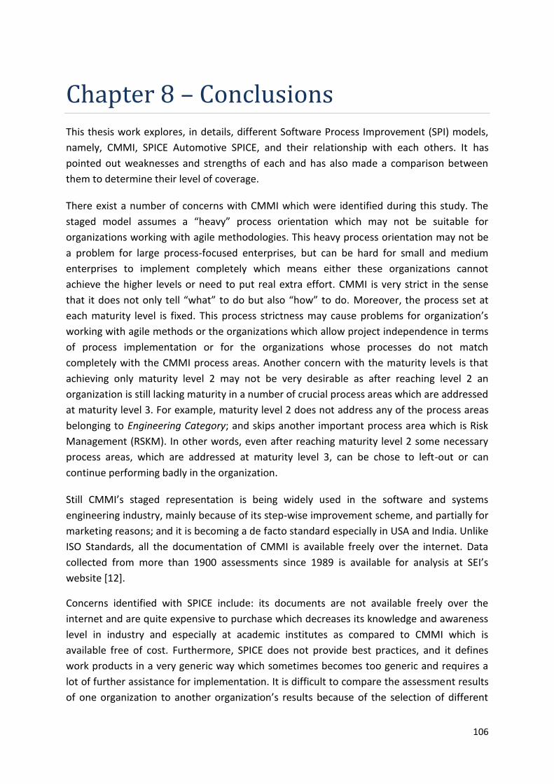
106
Chapter 8 – Conclusions
This thesis work explores, in details, different Software Process Improvement (SPI) models,
namely, CMMI, SPICE Automotive SPICE, and their relationship with each others. It has
pointed out weaknesses and strengths of each and has also made a comparison between
them to determine their level of coverage.
There exist a number of concerns with CMMI which were identified during this study. The
staged model assumes a “heavy” process orientation which may not be suitable for
organizations working with agile methodologies. This heavy process orientation may not be
a problem for large process-focused enterprises, but can be hard for small and medium
enterprises to implement completely which means either these organizations cannot
achieve the higher levels or need to put real extra effort. CMMI is very strict in the sense
that it does not only tell “what” to do but also “how” to do. Moreover, the process set at
each maturity level is fixed. This process strictness may cause problems for organization’s
working with agile methods or the organizations which allow project independence in terms
of process implementation or for the organizations whose processes do not match
completely with the CMMI process areas. Another concern with the maturity levels is that
achieving only maturity level 2 may not be very desirable as after reaching level 2 an
organization is still lacking maturity in a number of crucial process areas which are addressed
at maturity level 3. For example, maturity level 2 does not address any of the process areas
belonging to Engineering Category; and skips another important process area which is Risk
Management (RSKM). In other words, even after reaching maturity level 2 some necessary
process areas, which are addressed at maturity level 3, can be chose to left-out or can
continue performing badly in the organization.
Still CMMI’s staged representation is being widely used in the software and systems
engineering industry, mainly because of its step-wise improvement scheme, and partially for
marketing reasons; and it is becoming a de facto standard especially in USA and India. Unlike
ISO Standards, all the documentation of CMMI is available freely over the internet. Data
collected from more than 1900 assessments since 1989 is available for analysis at SEI’s
website [12].
Concerns identified with SPICE include: its documents are not available freely over the
internet and are quite expensive to purchase which decreases its knowledge and awareness
level in industry and especially at academic institutes as compared to CMMI which is
available free of cost. Furthermore, SPICE does not provide best practices, and it defines
work products in a very generic way which sometimes becomes too generic and requires a
lot of further assistance for implementation. It is difficult to compare the assessment results
of one organization to another organization’s results because of the selection of different

107
processes at different organization. On the other hand, CMMI appraisals provide a single
maturity level rating of an organization which can be easily compared with other
organizations’ maturity rating. Another concern is if processes can be improved
independently of other processes and different processes can work at different capability
levels, then does it make sense to have high capability level development processes with low
capability testing processes or low capability management processes?
One of the main differences in A-SPICE as compared to SPICE and CMMI-DEV is that
Acquisition process group is made more detailed and elaborated according to automotive
industry needs as it is a very common trend among Original Equipment Manufacturers
(OEMs) in automotive industry to involve software suppliers. In addition, A-SPICE processes
are made adaptable to the parallel hardware/software/system development and multiple
software release cycles approaches of automotive industry. Change Request Management
and Configuration Management processes are of major concern in this regard.
A main concern with the HIS Scope of Automotive SPICE is that it is missing some important
processes, such as, Risk Management, Measurement, and Process Improvement. But still it
can be a “good start” for the process improvement journey.
If we assume maturity level 2 of CMMI to be the minimum required level of an
organization’s maturity, then the coverage of process areas at maturity level 2 is very low.
Maturity level 2 is missing all the process areas from Engineering and Process Management
categories, plus it is missing another important process area which is Risk Management
(RSKM). On the other hand, if we consider SPICE’s claim of independence in process
selection for improvement and that the different processes can operate at different
capability levels at the same time; it may be easier to claim these things theoretically, but in
the real world it can cause severe problems. For example, higher capability level
development processes with lower capability level testing processes may affect the overall
performance of engineering process group. Or a high capability level engineering process
group working together with a lower capability level support process group can cause
troubles in both areas of organization. In other words, capability level of one process or
process groups is not completely independent from the other process or process group.
They will eventually affect each other, sooner or later.
If we compare CMMI’s maturity level 2 process areas with HIS Scope’s minimum required set
of processes, we can see that the process coverage in HIS Scope is better as it includes
processes from engineering, management, support, and acquisition process groups. Still, like
CMMI’s maturity level 2, it is missing Risk Management and Process Improvement processes
which are really important. Another important process which is missing in HIS Scope is
Measurement but is included in CMMI’s maturity level 2, meaning that CMMI start
measuring processes from the very beginning of process improvement. A counter argument
to this is that measurements are useful to perform after improving the processes to a certain
108
level; it may not be a very good approach to start measuring the processes before improving
them when they are performed in a disorganized way.
Comparison of these models in this thesis has shown that for most of the processes there
exists correspondence between the models. This means that organizations using one model
can adopt the processes of the other model by tailoring their current processes, or the
organizations using one model can interpret the assessment result to the other model using
process mapping rules. This makes both CMMI and SPICE/A-SPICE conformant and in
compliance with each other. Finally, it can be concluded that having knowledge of only one
of the process improvement models is not enough. Each of the models misses something at
some point which, at the same time, is might be incorporated in the other model. Therefore,
it is highly desirable and recommendable to gain knowledge of both (CMMI and SPICE/A-
SPICE) and consider both to get the best out of the process improvement venture.
The other part of the report explored a number of software development life cycle (SDLC)
models being used in the software industry and presented a comparison of them. Basically,
there exist two schools of thought about software lifecycles: Traditional and Agile. These
two schools can exist side by side, and a better approach is to combine suitable agile
practices with company’s current plan-driven approaches to get benefit out of both.
Moreover, by combining Agile and software process models like ISO SPICE, organizations can
get the best out of these in terms of cost, quality and time-to-market.
Although, it is possible to apply ISO/IEC SPICE standard processes in an Agile context, but it
does not mean at all that such a combination is possible without facing any problems.
Organizations can face problems like cultural shift, unfamiliarity with the new practices,
project scope, risks involved, and customer pressure. But this should not stop Agile
organizations to get their process maturity assessed by SPICE model and to make
improvements in those process areas accordingly [47]. This can incur a number of benefits
for organizations, such as they can be more structured in the way of their working and at the
same time flexible for accepting any change both in project scope and in processes, they can
standardize their own Agile practices to produce required outputs, they can improve their
planning and documentation levels, and can introduce a number of useful metrics and
measurements techniques.
Case study performed at AE has shown that it is possible to combine a company-tailored
traditional lifecycle model with Agile practices and A-SPICE processes, successfully. Although
there exist a number of issues, especially in team A regarding scope-change during the
development cycles and miscommunication, but model is still improving and teams are
working to sort out their process related issues. Another thing can be noticed here that
these two project teams started at two different points in time; at the start of team A, the
maturity of the organization was at a different level than after two years when team B
started. This means that organization has also matured and improved its ways of working
during this period of time.
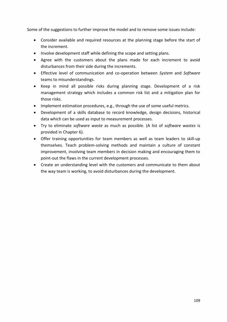
109
Some of the suggestions to further improve the model and to remove some issues include:
Consider available and required resources at the planning stage before the start of
the increment.
Involve development staff while defining the scope and setting plans.
Agree with the customers about the plans made for each increment to avoid
disturbances from their side during the increments.
Effective level of communication and co-operation between System and Software
teams to misunderstandings.
Keep in mind all possible risks during planning stage. Development of a risk
management strategy which includes a common risk list and a mitigation plan for
those risks.
Implement estimation procedures, e.g., through the use of some useful metrics.
Development of a skills database to record knowledge, design decisions, historical
data which can be used as input to measurement processes.
Try to eliminate software waste as much as possible. (A list of software wastes is
provided in Chapter 6).
Offer training opportunities for team members as well as team leaders to skill-up
themselves. Teach problem-solving methods and maintain a culture of constant
improvement, involving team members in decision making and encouraging them to
point-out the flaws in the current development processes.
Create an understanding level with the customers and communicate to them about
the way team is working, to avoid disturbances during the development.
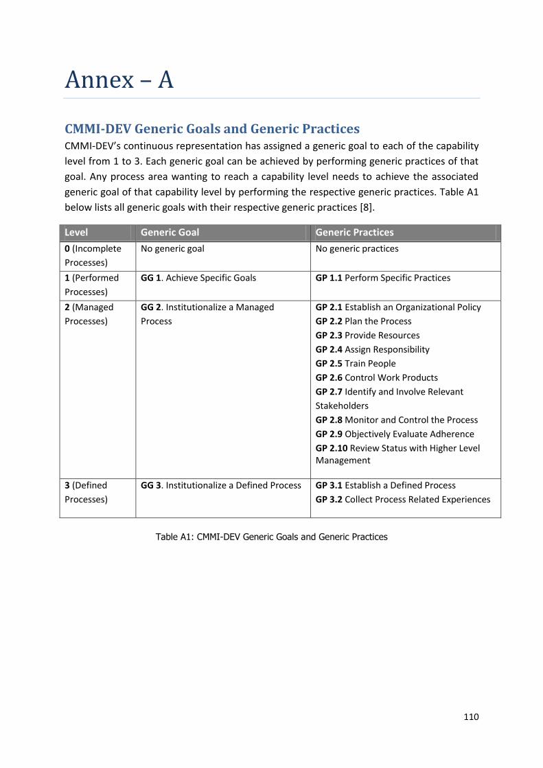
110
Annex – A
CMMI-DEV Generic Goals and Generic Practices CMMI-DEV’s continuous representation has assigned a generic goal to each of the capability
level from 1 to 3. Each generic goal can be achieved by performing generic practices of that
goal. Any process area wanting to reach a capability level needs to achieve the associated
generic goal of that capability level by performing the respective generic practices. Table A1
below lists all generic goals with their respective generic practices [8].
Level Generic Goal Generic Practices
0 (Incomplete
Processes)
No generic goal No generic practices
1 (Performed
Processes)
GG 1. Achieve Specific Goals GP 1.1 Perform Specific Practices
2 (Managed
Processes)
GG 2. Institutionalize a Managed
Process
GP 2.1 Establish an Organizational Policy
GP 2.2 Plan the Process
GP 2.3 Provide Resources
GP 2.4 Assign Responsibility
GP 2.5 Train People
GP 2.6 Control Work Products
GP 2.7 Identify and Involve Relevant
Stakeholders
GP 2.8 Monitor and Control the Process
GP 2.9 Objectively Evaluate Adherence
GP 2.10 Review Status with Higher Level Management
3 (Defined
Processes)
GG 3. Institutionalize a Defined Process GP 3.1 Establish a Defined Process
GP 3.2 Collect Process Related Experiences
Table A1: CMMI-DEV Generic Goals and Generic Practices

111
Annex – B
Automotive SPICE Process Attributes and Generic Practices Automotive SPICE has assigned process attribute(s) to each of the capability levels from 1 to
6. A process attribute represents a unique characteristic of the level. Any process wanting to
reach any specific capability level needs to achieve the process attribute(s) of that level by
performing the generic practices related to the process attribute. Table B1 below lists all
process attributes with their respective generic practices [21].
Level Process Attribute(s) Generic Practices
0 (Incomplete
Processes)
No process attribute No generic practices
1 (Performed
Processes)
PA 1.1 Process Performance GP 1.1.1 Achieve the process outcomes (by performing Base Practices of the process)
2 (Managed
Processes)
PA 2.1 Performance Management GP 2.1.1 Identify the objectives GP 2.1.2 Plan and monitor the performance GP 2.1.3 Adjust the performance of the process. GP 2.1.4 Define responsibilities and authorities GP 2.1.5 Identify and make available resources to perform the process GP 2.1.6 Manage the interfaces between involved parties.
PA 2.2 Work-Product Management
GP 2.2.1 Define the requirements for the work products. GP 2.2.2 Define the requirements for documentation and control GP 2.2.3 Identify, document and control the work products. GP 2.2.4 Review and adjust work products to meet the defined requirements.
3 (Defined
Processes)
PA 3.1 Process Definition
GP 3.1.1 Define the standard process that will support the deployment of the defined process. GP 3.1.2 Determine the sequence and interaction between processes GP 3.1.3 Identify the roles and competencies for performing the standard process. GP 3.1.4 Identify the required infrastructure and work environment GP 3.1.5 Determine suitable methods to monitor the effectiveness and suitability of the process.
PA 3.2 Process Deployment
GP 3.2.1 Deploy a defined process GP 3.2.2 Assign and communicate roles, responsibilities and authorities GP 3.2.3 Ensure necessary competencies for performing the defined process.

112
Level Process Attribute(s) Generic Practices
GP 3.2.4 Provide resources and information to support the performance GP 3.2.5 Provide adequate process infrastructure to support the performance GP 3.2.6 Collect and analyze data about performance of the process to demonstrate its suitability and effectiveness.
4 (Predictable processes)
PA 4.1 Process Measurement GP 4.1.1 Identify process information needs, in relation with business goals. GP 4.1.2 Derive process measurement objectives from process information needs. GP 4.1.3 Establish quantitative objectives GP 4.1.4 Identify product and process measures GP 4.1.5 Collect product and process measurement results through performing the defined process. GP 4.1.6 Use the results of the defined measurement to monitor and verify the achievement of the process performance objectives.
PA 4.2 Process Control
GP 4.2.1 Determine analysis and control techniques GP 4.2.2 Define parameters suitable to control the process performance. GP 4.2.3 Analyze process and product measurement results to identify variations in process performance. GP 4.2.4 Identify and implement corrective actions to address assignable causes. GP 4.2.5 Re-establish control limits following corrective action.
5 (Optimizing processes)
PA 5.1 Process Innovation
GP 5.1.1 Define the process improvement objectives GP 5.1.2 Analyze measurement data of the process to identify real and potential variations in the process performance. GP 5.1.3 Identify improvement opportunities of the process based on innovation and best practices. GP 5.1.4 Derive improvement opportunities GP 5.1.5 Define an implementation strategy
PA 5.2 Process Optimization
GP 5.2.1 Assess the impact of each proposed change GP 5.2.2. Manage the implementation of agreed changes GP 5.2.3 Evaluate the effectiveness of process change
Table B1: Automotive SPICE Process Attributes and Generic Practices

113
Annex – C
System Diagram [19]

114
Annex – D
Interview Questions Below are the questions which were asked during the interviews and an observation session
of a Software Activity cycle planning meeting (sprint planning meeting). Each interview was
approx. 2 hours long, whereas observation session was almost 8 hours long. As the
interviews were semi-structured, therefore not all of the questions were prepared from the
start; some of them appeared during these sessions.
1. When was this Project started?
2. Is it the only project your team is working on currently?
3. Which software lifecycle development model (Waterfall, Incremental, Agile etc) are
you using in your team?
4. How long is each Increment then?
5. Which tasks are included in each 4-weeks cycle?
6. How do you manage work inside your team?
7. Is your team is involved in all the activities of an Increment, including System Activity
and Test Activity?
8. This way of working means that Requirements are fixed as well as all the Planning is
done at the start. Is it so, and how do you do that?
9. How do you define the scope of the project, and who is responsible for that?
10. How often do you update the scope?
11. Who is responsible for defining features for an increment, and how do you do that?
12. Do you define the features for next increments as well?
13. Who are responsible for task definition and planning?
14. How do you estimate and prioritize tasks?
15. What problems do you face during a Software Activity cycle?
16. What happens if the development is not finished in one Increment?
17. How do you involve customers during the cycles?
18. How do you incorporate bug-fixes and customer feedback regarding the previous
Increments?
19. How do you communicate within your team, and with other teams?
20. What is the overall productivity of the team?
21. Why did you prefer Scrum? And what do you think about other Agile approaches
(e.g., Pair Programming and Test-Driven Development)?

115
References
[1] Klaus Hoermann; Markus Mueller; Lars Dittmann; Joerg Zimmer, “Automotive SPICE
in Practice: Surviving Implementation and Assessment”, First Edition, Rocky Nook,
ISBN: 978-1933952291, August 2008
[2] Agile Manifesto - http://agilemanifesto.org/, 15.04.2011
[3] Dr. N. Ehsan; A. Perwaiz; J. Arif; E. Mirza; A. Ishaque, “CMMI / SPICE based Process
Improvement”, IEEE 978-1-4244-6567-5/10, 2010
[4] Hans Sassenburg; David Kitson, “A Comparative Analysis of CMMI and Automotive
SPICE”, SEI 2006 - www.se-cure.ch/images/06-ESEPG1.pdf, 10.02.2011
[5] Fabio Bella; Klaus Hörmann; Bhaskar Vanamali, “From CMMI to SPICE – Experiences
on How to Survive a SPICE Assessment Having Already Implemented CMMI”, Springer,
2008
[6] Marcello Thiry; Alessandra Zoucas; Leornardo Tristão, “Mapping Process Capability
Models to Support Integrated Software Process Assessments”, CLEI ELECTRONIC
JOURNAL, VOLUME 13, NUMBER 1, PAPER 4, APRIL 2011
[7] Software Engineering Institute - http://www.sei.cmu.edu/, 12.02.2011
[8] “CMMI® for Development version 1.3 (CMMI-DEV V1.3)”, TECHNICAL REPORT,
CMU/SEI-2010-TR-033, NOVEMBER 2010 - http://www.sei.cmu.edu, 05.02.2011
[9] Capability Maturity Model Integration -
http://en.wikipedia.org/wiki/Capability_Maturity_Model_Integration, 15.02.2011
[10] CMMI Overview - http://www.adnetcmm.com/cmmi-overview.html, 15.02.2011
[11] CMMI General Description - http://www.esi.es/index.php?op=15.1.1, 20.02.2011
[12] Han Van Loon, “Process Assessment and ISO/IEC 15504 (A Reference Book)”, Second
Edition, Springer, ISBN: 978-0387231723, June 2007
[13] “ISO/IEC TR 15504 - 2: Information Technology – Software Process Assessment”. A
Reference Model for Processes and Process Capability, 1998
[14] Mark C. Paulk; Michael D. Konrad, “An Overview of SPICE’s Model for Process
Management”, Proceedings of the Fifth International Conference on Software
Quality, Austin, TX, 23-26 October 1995
[15] ISO/IEC 15504 – http://en.wikipedia.org/wiki/ISO/IEC_15504, 20.02.2011
116
[16] Bernard Londeix, “Measurement for Automotive SPICE”, January 2008 –
www.measuresw.com/library/Papers/Londeix/07BELAutoSPICE.pdf, 25.02.2011
[17] Hersteller Initiative Software (HIS) - Working Group Assessment, 2008 –
http://portal.automotive-his.de/images/pdf/ProcessAssessment/his-wg-
assessments_v31_07-06-08.pdf, 28.02.2011
[18] Automotive SPICE – http://www.automotivespice.com/web/Introduction.html,
04.03.2011
[19] Automotive SPICE – “Process Reference Model (PRM) v4.5”, Automotive SIG, The
SPICE User Group, 2010 –
http://www.automotivespice.com/automotiveSIG_PRM_v45.pdf, 10.03.2011
[20] What is SPICE? –
http://www.wibas.com/publications/spice__automotive_spice/what_is_spice/index_
en.html, 18.03.2011
[21] Automotive SPICE – “Process Assessment Model (PAM) v2.5”, Automotive SIG, The
SPICE User Group, 2010 –
http://www.automotivespice.com/automotiveSIG_PAM_v25.pdf, 10.03.2011
[22] Maria Teres a Bald assarre; Mario Piattini; Francisco J. Pino; Giuseppe Visaggio,
“Comparing ISO/IEC 12207 and CMMI-DEV: towards a mapping of ISO/IEC 15504-7”,
IEEE 978-1-4244-3723-8/09, 2009
[23] CMMI EVALUATION – CAPABILITY MATURITY MODEL INTEGRATION MAPPING TO
ISO/IEC 15504-2:1998, Software Quality Institute, Griffith University, 2000 –
http://www.sqi.gu.edu.au/cmmi/report/docs/MappingReport.pdf, 25.03.2011
[24] Guidelines for Successful Acquisition and Management of Software Intensive Systems
(GSAM), U.S. Air Force's Software Technology Support Center, 2003 –
http://www.stsc.hill.af.mil/resources/tech_docs/gsam4.html, 20.03.2011
[25] Stefan Saarnak; Björn Gustafsson, “A Comparison of Lifecycles – Agile software
processes vs. projects in non-agile companies”, BTH, 2003
[26] Software Development Process –
http://en.wikipedia.org/wiki/Software_development_process, 10.04.2011
[27] Software Development Life Cycle Models –
http://codebetter.com/raymondlewallen/2005/07/13/software-development-life-
cycle-models/, 08.04.2011

117
[28] SOFTWARE DEVELOPMENT PROCESS - Software Life Cycle Models –
http://www.itimes.com/public/people/iti402300/blog/SOFTWARE-DEVELOPMENT-
PROCESSSoftware-Life-Cycle-Models, 12.04.2011
[29] Software Life Cycle Models –
http://www.softpanorama.org/SE/software_life_cycle_models.shtml, 15.04.2011
[30] Hans van Vliet, “Software Engineering: Principles and Practice”, Third Edition, Wiley,
ISBN: 978-0470031469, July 2008
[31] Nayan B. Ruparelia, “Software Development Lifecycle Models”, ACM SIGSOFT
Software Engineering Notes - Volume 35 Number 3, May 2010
[32] IBM Rational Unified Process –
http://en.wikipedia.org/wiki/IBM_Rational_Unified_Process, 25.04.2011
[33] M. A. Awad, “A Comparison between Agile and Traditional Software Development
Methodologies”, The University of Western Australia, 2005
[34] The Advantages and Disadvantages / Best Practices of RUP Software Development –
http://www.my-project-management-expert.com/the-advantages-and-
disadvantages-of-rup-software-development.html, 26.04.2011
[35] Donis Marshall; John Bruno, “Solid Code”, First Edition, Microsoft Press, ISBN: 978-
0735625921, February 2009
[36] Principles behind the Agile Manifesto –
http://www.agilemanifesto.org/principles.html, 30.04.2011
[37] Kent Beck; Cynthia Andres, “Extreme Programming Explained”, Second Edition,
Addison-Wesley Professional, ISBN: 978-0321278654, November 2004
[38] Software Lifecycle Models –
www.nada.kth.se/~karlm/prutt05/lectures/prutt05_lec6.ppt, 22.04.2011
[39] Extreme Programming – www.csis.pace.edu/~ctappert/cs616-02/pres-xp.ppt,
30.04.2011
[40] Extreme Programming – http://en.wikipedia.org/wiki/Extreme_Programming,
28.04.2011
[41] Scrum (development) – http://en.wikipedia.org/wiki/Scrum_(development),
02.05.2011
[42] Seven Principles of Lean Software Development -
http://agilesoftwaredevelopment.com/leanprinciples, 10.05.2011

118
[43] James P. Womack; Daniel T. Jones, “Lean Thinking”, 2nd Edition, Free Press, ISBN:
978-0684810355, November 2010
[44] Mary Poppendieck; Tom Poppendieck, “Lean Software Development: An Agile
Toolkit”, First Edition, Addison-Wesley Professional, ISBN:978-0321150783, May 2003
[45] Curt Hibbs; Steve Jewett; Mike Sullivan, “The Art of Lean Software Development”,
First Edition, O'Reilly Media, ISBN: 978-0596517311, January 2009
[46] Fergal Mc Caffery; Minna Pikkarainen; Ita Richardson, “AHAA –Agile, Hybrid
Assessment Method for Automotive, Safety Critical SMEs”, ACM 978-1-60558-079-
1/08/05, 2008
[47] Giuseppe Lami; Fabio Falcini, “Is ISO/IEC 15504 Applicable to Agile Methods?”,
Springer, 2009
[48] Comparison to Traditional Development –
http://www.agilekiwi.com/other/agile/comparison-to-traditional-development/,
12.05.2011
[49] Quick Introduction To Agile Software Development –
http://www.indicthreads.com/1439/quick-introduction-to-agile-software-
development/, 02.05.2011
[50] B. Boehm, “Get Ready for Agile Methods, with Care”, IEEE Software Development,
pp.64-69, January 2002.
119
Acronyms and Abbreviations
A- SPICE Automotive SPICE
AE Initials of the name of the company
ARC Appraisal Requirements for CMMI
CMF CMMI Model Foundation
CMMI Capability Maturity Model Integration
CMMI-DEV Capability Maturity Model Integration for Development
CMS Configuration Management System
DoD Definition of Done
ECUs Electronic Control Units
HIS Hersteller Initiative Software
IS International Standard
ISO International Standard Organization
OEMs Original Equipment Manufacturers
PA Process Area
PA Process Attribute
PAM Process Assessment Model
PRM Process Reference Model
QAC Quality Assurance Check
ROI Return On Investment
RUP Rational Unified Process
SCAMPI Standard CMMI Appraisal Method for Process Improvement
SDLC Software Development Life Cycle
SEI Software Engineering Institute
SIG Special Interest Group
SPI Software Process Improvement
SPICE Software Process Improvement and Capability dEtermination
SQA Software Quality Assurance
SRS Software Requirements Specification
TDD Test Driven Development
TR Technical Report
UML Unified Modeling Language
USDOD US Department of Defense


