

Intel® NUC Rugged Board Element CMB1ABA, CMB1ABB and CMB1ABC Product Specification
Revision 1.3
Regulatory Model: CMB1AB
July 2020
Intel® NUC Rugged Board Element CMB1ABA, CMB1ABB or CMB1ABC may contain design defects or errors known as errata that may cause the
product to deviate from published specifications. Current characterized errata, if any, are documented in in this product specification.

Revision History
Revision Revision History Date
1.0 First release October 2019
1.01 Ethernet model number correction, Updated Figure 5 December 2019
1.2 Added CMB1ABC June 2020
1.3 Added back panel power connector section, clarified M.2 slot support and added
vPro® section.
July 2020
Disclaimer
This product specification applies only to the standard Intel® NUC Rugged Board Element with product codes
CMB1ABA, CMB1ABB and CMB1ABC.
INFORMATION IN THIS DOCUMENT IS PROVIDED IN CONNECTION WITH INTEL® PRODUCTS. NO LICENSE, EXPRESS OR IMPLIED, BY ESTOPPEL OR OTHERWISE, TO ANY INTELLECTUAL PROPERTY RIGHTS IS GRANTED BY THIS DOCUMENT.
EXCEPT AS PROVIDED IN INTEL’S TERMS AND CONDITIONS OF SALE FOR SUCH PRODUCTS, INTEL ASSUMES NO LIABILITY WHATSOEVER, AND INTEL DISCLAIMS ANY EXPRESS OR IMPLIED WARRANTY, RELATING TO SALE AND/OR USE OF INTEL PRODUCTS INCLUDING LIABILITY OR WARRANTIES RELATING TO FITNESS FOR A PARTICULAR PURPOSE,
MERCHANTABILITY, OR INFRINGEMENT OF ANY PATENT, COPYRIGHT OR OTHER INTELLECTUAL PROPERTY RIGHT. UNLESS OTHERWISE AGREED IN WRITING BY INTEL, THE INTEL PRODUCTS ARE NOT DESIGNED NOR INTENDED FOR ANY APPLICATION IN WHICH THE FAILURE OF THE INTEL PRODUCT COULD CREATE A SITUATION WHERE PERSONAL
INJURY OR DEATH MAY OCCUR.
All Intel® NUC Rugged Board Elements are evaluated as Information Technology Equipment (I.T.E.) for use in personal computers (PC) for installation in homes, offices, schools, computer rooms, and similar locations. The suitability of this
product for other PC or embedded non-PC applications or other environments, such as medical, industrial, alarm systems, test equipment, etc. may not be supported without further evaluation by Intel.
Intel Corporation may have patents or pending patent applications, trademarks, copyrights, or other intellectual property
rights that relate to the presented subject matter. The furnishing of documents and other materials and information does not provide any license, express or implied, by estoppel or otherwise, to any such patents, trademarks, copyrights, or other intellectual property rights.
Intel may make changes to specifications and product descriptions at any time, without notice.
Designers must not rely on the absence or characteristics of any features or instructions marked “reserved” or “undefined.” Intel reserves these for future definition and shall have no responsibility whatsoever for conflicts or
incompatibilities arising from future changes to them.
Intel processor numbers are not a measure of performance. Processor numbers differentiate features within each processor family, not across different processor families: Go to:
Learn About Intel® Processor Numbers
Intel® NUC Rugged Board Elements may contain design defects or errors known as errata, which may cause the product to deviate from published specifications. Current characterized errata are available on request.
Contact your local Intel sales office or your distributor to obtain the latest specifications before placing your product order.
Intel, the Intel logo and Intel Core are trademarks of Intel Corporation in the U.S. and/or other countries.
* Other names and brands may be claimed as the property of others.
Copyright © 2020 Intel Corporation. All rights reserved.
iii
Preface
This Product Specification specifies the layout, components, connectors, power and
environmental features for the Intel® NUC Rugged Board Element CMB1ABA, CMB1ABB
CMB1ABC.
NOTE
In this document, the use of “Intel® NUC Rugged Board Element” will refer to the CMB1ABA,
CMB1ABB and CMB1ABC versions of the Intel® NUC Rugged Board Element.
Intended Audience The document is intended to provide technical information about Intel® NUC Rugged Board
Element and its components to the vendors, system integrators, and other engineers and
technicians who need this level of information. It is specifically not intended for general
audiences.
What This Document Contains Chapter Description
1 A description of the Intel ® NUC Rugged Board Element features.
2 A technical description of the Intel ® NUC Rugged Board Element.
Typographical Conventions This section contains information about the conventions used in this specification. Not all of
these symbols and abbreviations appear in all specifications of this type.
Notes, Cautions, and Warnings
NOTE
Notes call attention to important information.
CAUTION
Cautions are included to help you avoid damaging hardware or losing data.

iv
Other Common Notation
# Used after a signal name to identify an active-low signal (such as USBP0#)
GB Gigabyte (1,073,741,824 bytes)
GB/s Gigabytes per second
Gb/s Gigabits per second
KB Kilobyte (1024 bytes)
Kb Kilobit (1024 bits)
kb/s 1000 bits per second
MB Megabyte (1,048,576 bytes)
MB/s Megabytes per second
Mb Megabit (1,048,576 bits)
Mb/s Megabits per second
TDP Thermal Design Power
Xxh An address or data value ending with a lowercase h indicates a hexadecimal value.
x.x V Volts. Voltages are DC unless otherwise specified.
* This symbol is used to indicate third-party brands and names that are the property of their respective
owners.
Intel® NUC Rugged Board Element Identification Information
Intel® NUC Rugged Board Element Identification Information
AA Revision Product Code Board Type Notes
K53775-202 BKCMB1ABA Expandable 1
K53777-202 BKCMB1ABB Dual LAN 1
K53779-302 BKCMB1ABC Six HDMI 1
Notes:
1. The AA number is found on the top of the board
Specification Changes or Clarifications The table below indicates the Specification Changes or Specification Clarifications that apply to
the Intel® NUC Rugged Board Element CMB1ABA, CMB1ABB and CMB1ABC.
Specification Changes or Clarifications
Date Type of Change Description of Changes or Clarifications
Errata Current characterized errata, if any, are documented in Section 3 of this Product Specification.

v
Contents
Revision History ............................................................................................................... ii
Disclaimer .................................................................................................................................................................. ii
Preface .............................................................................................................................. iii
Intended Audience ................................................................................................................................................ iii
What This Document Contains ........................................................................................................................ iii
Typographical Conventions .............................................................................................................................. iii
Intel® NUC Rugged Board Element Identification Information ........................................................... iv
Specification Changes or Clarifications ........................................................................................................ iv
Errata ........................................................................................................................................................................... iv
Contents ............................................................................................................................ v
1 Product Description .................................................................................................. 7
1.1 Overview ......................................................................................................................................................... 7
1.2 Version Summary ........................................................................................................................................ 7
1.3 Feature Summary ........................................................................................................................................ 8
2 Technical Reference .................................................................................................. 9
2.1 Block Diagrams ............................................................................................................................................. 9
2.2 Features ........................................................................................................................................................ 12
2.2.1 CMB1ABC HDMI Port Configuration .............................................................................. 15
2.3 USB 2.0 Headers ....................................................................................................................................... 16
2.4 Serial Port Headers .................................................................................................................................. 16
2.5 Fan Header .................................................................................................................................................. 16
2.6 Power Input Connector .......................................................................................................................... 16
2.7 USB 3.0 Header ......................................................................................................................................... 17
2.8 Front Panel Header.................................................................................................................................. 17
2.9 Power Connector ...................................................................................................................................... 17
2.10 Embedded DisplayPort Connector ................................................................................................... 18
2.11 Display Emulation .................................................................................................................................... 19
2.12 Power ....................................................................................................................................................... 20
2.13 Intel® vPro® Technology ........................................................................................................................ 20
2.14 Wireless Enable/Disable Jumper ...................................................................................................... 21
Mechanical .............................................................................................................................................................. 22
2.15 Thermal ....................................................................................................................................................... 25
2.16 Environmental ........................................................................................................................................... 25
3 Characterized Errata ............................................................................................... 26

vi
Figures
Figure 1. CMB1ABA Block Diagram ....................................................................................................................... 9
Figure 2. CMB1ABB Block Diagram..................................................................................................................... 10
Figure 3. CMB1ABC Block Diagram..................................................................................................................... 11
Figure 4. CMB1ABA Features ................................................................................................................................ 12
Figure 5. CMB1ABB Features................................................................................................................................. 13
Figure 6. CMB1ABC Features ................................................................................................................................ 14
Figure 7. CMB1ABC HDMI Port Configuration................................................................................................ 15
Figure 8. Wireless Enable/Disable Jumper Location .................................................................................. 21
Figure 9. CMB1ABA Dimensions .......................................................................................................................... 22
Figure 10. CMB1ABB Dimensions ....................................................................................................................... 23
Figure 11. CMB1ABC Dimensions ....................................................................................................................... 24
Tables
Table 1. Intel® NUC Rugged Board Element Version Summary ................................................................ 7
Table 2. Feature Summary ........................................................................................................................................ 8
Table 3. CMB1ABA Features .................................................................................................................................. 12
Table 4. CMB1ABB Features .................................................................................................................................. 13
Table 5. CMB1ABC Features .................................................................................................................................. 14
Table 6. HDMI Port Configuration and Supported Resolutions ............................................................. 15
Table 7. USB 2.0 Header Pinout ........................................................................................................................... 16
Table 8. Serial Port Header Pinout ..................................................................................................................... 16
Table 9. Fan Header Pinout ................................................................................................................................... 16
Table 10. Power Input Connector Pinout ........................................................................................................ 16
Table 11. USB 3.0 Header Pinout ........................................................................................................................ 17
Table 12. Front Panel Header Pinout ................................................................................................................ 17
Table 13. eDP Connector Pinout ......................................................................................................................... 18
Table 14. Wireless Enable/Disable Jumper Settings .................................................................................. 21
Table 15. Environmental Specifications ........................................................................................................... 25

Intel® NUC Rugged Board Element Product Specification
7
1 Product Description
1.1 Overview The Intel® NUC Rugged Board Element is a board only solution for the Intel® NUC Compute
Element and consists of a connector for the Intel® NUC Compute Element to plug into along with
input/output connectors and headers.
The Intel® NUC Rugged Board Element requires a compatible Intel® NUC Compute Element in
order to operate.
For information on compatible devices for use with the Intel® NUC Rugged Board Element see
http://www.intel.com/NUCElements.
1.2 Version Summary There are three different board versions of this model of Intel® NUC Rugged Board Element which
are summarized in Table 1. Unless otherwise noted in this document, not all features are
available on all versions of the Intel® NUC Rugged Board Element.
Table 1. Intel® NUC Rugged Board Element Version Summary
Version HDMI
Ports
M.2
Connectors
eDP
Connectors
LAN USB 2
Ports
USB 3
Ports
USB 2.0
Headers
USB 3.0
Headers
Serial
Port
Headers
CMB1ABA 2 2 1 1 1 3 2 1 2
CMB1ABB 2 2 0 2 3 3 0 1 2
CMB1ABC 6 2 0 1 1 3 2 1 2
NOTE
Intel® NUC Rugged Board Elements listed in Table 1 have been certified for use as a component in
Information Technology Equipment in certain countries. The system integrator is responsible for
testing and acquiring any additional country-specific regulatory approvals, including all system-
wide certifications.
To find information about… Visit this World Wide Web site:
Intel® NUC Element https://www.intel.com/NUCElements
Intel® NUC Element Support https://www.intel.com/NUCElementsSupport
Intel® NUC Element Warranty Information http://www.intel.com/NUCWarranty
Available configurations for Intel® NUC Rugged
Board Element
https://ark.intel.com
Intel Processors https://www.intel.com/processors
Intel Graphics https://www.intel.com/graphics
Intel Wireless https://www.intel.com/wireless
Intel Technologies https://www.intel.com/technology

Intel® NUC Rugged Board Element Product Specification
8
1.3 Feature Summary Table 2 summarizes the major features of the Intel® NUC Rugged Board Elements.
Table 2. Feature Summary
Board Size • CMB1ABA: 170 millimeters by 136.4 millimeters
• CMB1ABB: 170 millimeters by 136.4 millimeters
• CMB1ABC: 200 millimeters by 136.4 millimeters
Graphics Outputs Integrated graphics support with Intel® HD Graphics Technology
• Two HDMI 2.0a
• Four HDMI 1.4 on CMB1ABC
• One Embedded DisplayPort (eDP) on CMB1ABA
• Built in CEC for all HDMI ports
• High-Bandwidth Digital Content Protection support for content protection
o HDCP 1.4 and 2.2 supported via HDMI
• Resolutions and refresh rates supported
o Up to 4K @ 60Hz
o Up to 1080p @ 120Hz
Audio Intel® High Definition (Intel® HD) Audio via HDMI
Storage • One M.2 22x80 Key M slot for PCIe x4 NVMe or SATA SSDs
• One M.2 22x80 Key M slot for PCIe x4 NVMe or PCIe add in devices
Wireless LAN Intel® NUC Compute Element supplies the solution, antennas will be required
Wired LAN • Intel® Ethernet Connection I219-LM (Support for Intel® vPro™ Technology when using a
vPro™ enabled NUC Compute Element)
• Intel® Ethernet Controller I211-AT (CMB1ABB only)
USB 2.0 • CMB1ABA: 3 (1 Front Panel, 2 Internal Headers)
• CMB1ABB: 2 (1 Front Panel, 2 Back Panel)
• CMB1ABC: 3 (1 Front Panel, 2 Internal Headers)
USB 3.0 1 Internal Header
USB 3.x1 3 (1 Front Panel, 2 Back Panel)
Serial Ports 2 Internal Headers
Operating Systems
Support (64-bit only)
• Windows* 10 Home
• Windows 10 Pro
• Windows 10 Enterprise
• Windows 10 Education
• Windows 10 IoT Enterprise
• Some Linux* operating systems may be compatible. Check with the specific Linux
distribution to make sure that support is available for this platform.
Connector Supported Lotes APCI0468-P001A01 Edge Mount Connector
Sustained Operation
(24x7 usage)
Sustained Operation is defined as 24x7 operation for 5 years with 50% system utilization on
average, with an expected service rate of 1% per year during this period.
1 USB 3.x port speed is determined by the Intel® NUC Compute Element.
Intel® NUC Rugged Board Element Product Specification
9
2 Technical Reference
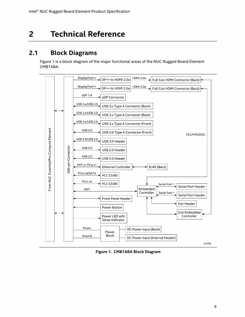
2.1 Block Diagrams Figure 1 is a block diagram of the major functional areas of the NUC Rugged Board Element
CMB1ABA.
Figure 1. CMB1ABA Block Diagram

Intel® NUC Rugged Board Element Product Specification
10
Figure 2 is a block diagram of the major functional areas of the NUC Rugged Board Element
CMB1ABB.
Figure 2. CMB1ABB Block Diagram

Intel® NUC Rugged Board Element Product Specification
11
Figure 3 is a block diagram of the major functional areas of the NUC Rugged Board Element
CMB1ABC.
Figure 3. CMB1ABC Block Diagram
Intel® NUC Rugged Board Element Product Specification
12
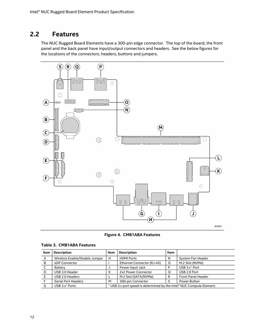
2.2 Features The NUC Rugged Board Elements have a 300-pin edge connector. The top of the board, the front
panel and the back panel have input/output connectors and headers. See the below figures for
the locations of the connectors, headers, buttons and jumpers.
Figure 4. CMB1ABA Features
Table 3. CMB1ABA Features
Item Description Item Description Item
A Wireless Enable/Disable Jumper H HDMI Ports N System Fan Header
B eDP Connector I Ethernet Connector (RJ-45) O M.2 Slot (NVMe)
C Battery J Power Input Jack P USB 3.x1 Port
D USB 3.0 Header K 2x2 Power Connector Q USB 2.0 Port
E USB 2.0 Headers L M.2 Slot (SATA/NVMe) R Front Panel Header
F Serial Port Headers M 300-pin Connector S Power Button
G USB 3.x1 Ports 1 USB 3.x port speed is determined by the Intel® NUC Compute Element.
Intel® NUC Rugged Board Element Product Specification
13
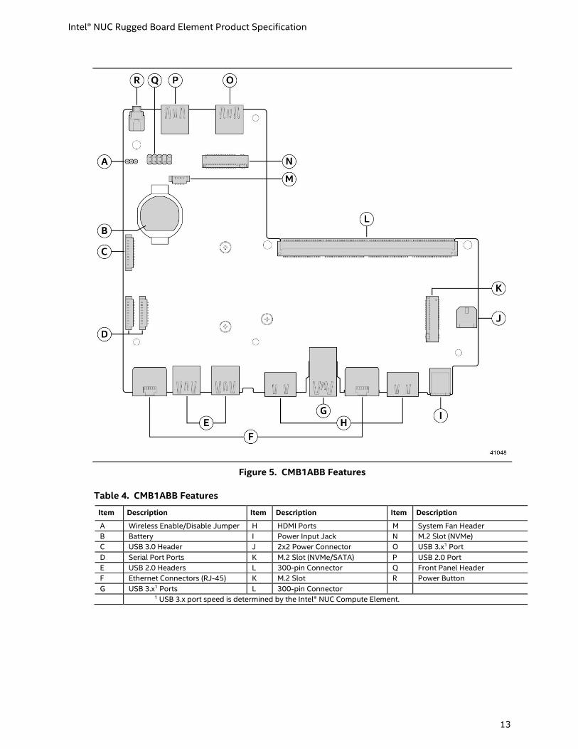
Figure 5. CMB1ABB Features
Table 4. CMB1ABB Features
Item Description Item Description Item Description
A Wireless Enable/Disable Jumper H HDMI Ports M System Fan Header
B Battery I Power Input Jack N M.2 Slot (NVMe)
C USB 3.0 Header J 2x2 Power Connector O USB 3.x1 Port
D Serial Port Ports K M.2 Slot (NVMe/SATA) P USB 2.0 Port
E USB 2.0 Headers L 300-pin Connector Q Front Panel Header
F Ethernet Connectors (RJ-45) K M.2 Slot R Power Button
G USB 3.x1 Ports L 300-pin Connector
1 USB 3.x port speed is determined by the Intel® NUC Compute Element.

Intel® NUC Rugged Board Element Product Specification
14
Figure 6. CMB1ABC Features
Table 5. CMB1ABC Features
Item Description Item Description Item
A Wireless Enable/Disable Jumper H USB 3.x3 Ports O USB 3.x3 Port
B Battery I Ethernet Connector (RJ-45) P System Fan Header
C USB 3.0 Header J Power Input Jack Q USB 2.0 Port
D USB 2.0 Headers K 2x2 Power Connector R Front Panel Header
E Serial Port Headers L M.2 Slot (NVMe/SATA) S Power Button
F HDMI Ports B1 M 300-Pin Connector
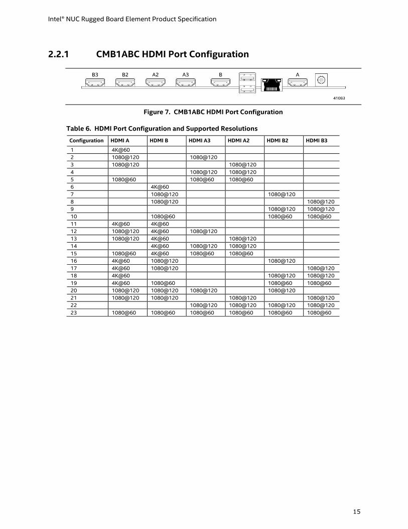
G HDMI Ports A2 N M.2 Slot (NVMe) 1 Group B HDMI ports are configured from left to right as B, B2 and B3. See Table 6. 2 Group A HDMI ports are configured from left to right as A, A3 and A2. See Table 6. 3 USB 3.x port speed is determined by the Intel® NUC Compute Element.
Intel® NUC Rugged Board Element Product Specification
15
2.2.1 CMB1ABC HDMI Port Configuration
Figure 7. CMB1ABC HDMI Port Configuration
Table 6. HDMI Port Configuration and Supported Resolutions
Configuration HDMI A HDMI B HDMI A3 HDMI A2 HDMI B2 HDMI B3
1 4K@60
2 1080@120 1080@120
3 1080@120 1080@120
4 1080@120 1080@120
5 1080@60 1080@60 1080@60
6 4K@60
7 1080@120 1080@120
8 1080@120 1080@120
9 1080@120 1080@120
10 1080@60 1080@60 1080@60
11 4K@60 4K@60
12 1080@120 4K@60 1080@120
13 1080@120 4K@60 1080@120
14 4K@60 1080@120 1080@120
15 1080@60 4K@60 1080@60 1080@60
16 4K@60 1080@120 1080@120
17 4K@60 1080@120 1080@120
18 4K@60 1080@120 1080@120
19 4K@60 1080@60 1080@60 1080@60
20 1080@120 1080@120 1080@120 1080@120
21 1080@120 1080@120 1080@120 1080@120
22 1080@120 1080@120 1080@120 1080@120
23 1080@60 1080@60 1080@60 1080@60 1080@60 1080@60
Intel® NUC Rugged Board Element Product Specification
16
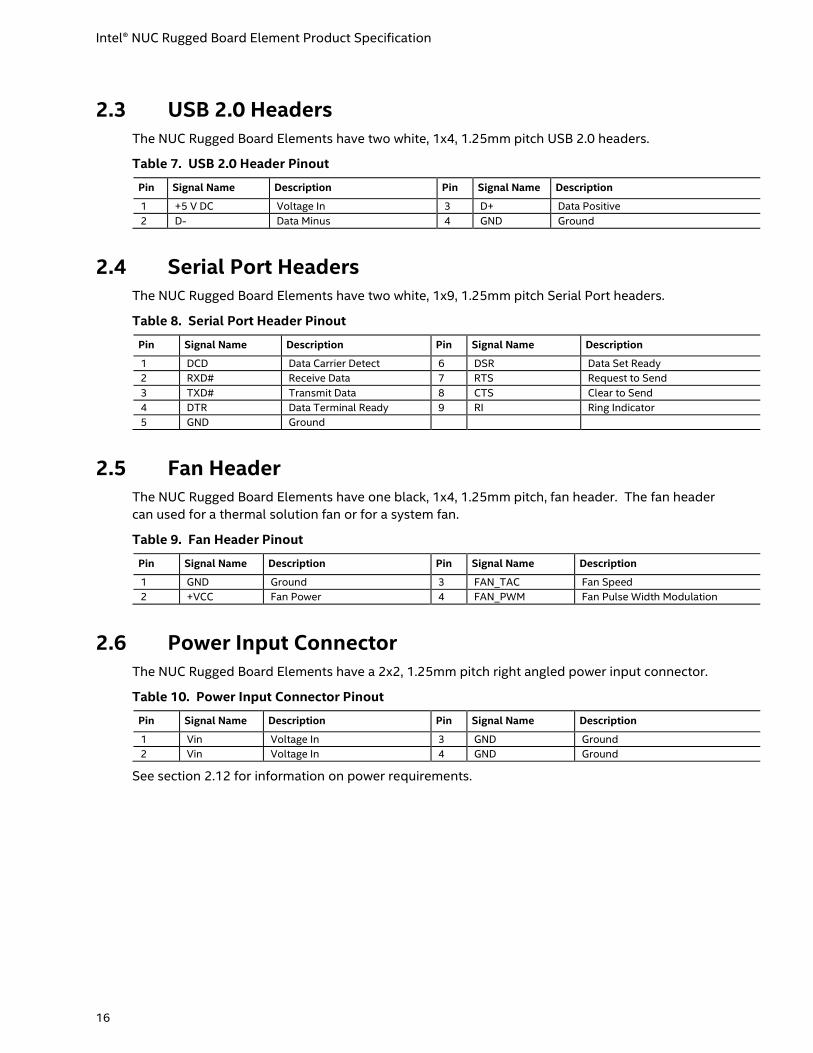
2.3 USB 2.0 Headers The NUC Rugged Board Elements have two white, 1x4, 1.25mm pitch USB 2.0 headers.
Table 7. USB 2.0 Header Pinout
Pin Signal Name Description Pin Signal Name Description
1 +5 V DC Voltage In 3 D+ Data Positive
2 D- Data Minus 4 GND Ground
2.4 Serial Port Headers The NUC Rugged Board Elements have two white, 1x9, 1.25mm pitch Serial Port headers.
Table 8. Serial Port Header Pinout
Pin Signal Name Description Pin Signal Name Description
1 DCD Data Carrier Detect 6 DSR Data Set Ready
2 RXD# Receive Data 7 RTS Request to Send
3 TXD# Transmit Data 8 CTS Clear to Send
4 DTR Data Terminal Ready 9 RI Ring Indicator
5 GND Ground
2.5 Fan Header The NUC Rugged Board Elements have one black, 1x4, 1.25mm pitch, fan header. The fan header
can used for a thermal solution fan or for a system fan.
Table 9. Fan Header Pinout
Pin Signal Name Description Pin Signal Name Description
1 GND Ground 3 FAN_TAC Fan Speed
2 +VCC Fan Power 4 FAN_PWM Fan Pulse Width Modulation
2.6 Power Input Connector The NUC Rugged Board Elements have a 2x2, 1.25mm pitch right angled power input connector.
Table 10. Power Input Connector Pinout
Pin Signal Name Description Pin Signal Name Description
1 Vin Voltage In 3 GND Ground
2 Vin Voltage In 4 GND Ground
See section 2.12 for information on power requirements.
Intel® NUC Rugged Board Element Product Specification
17
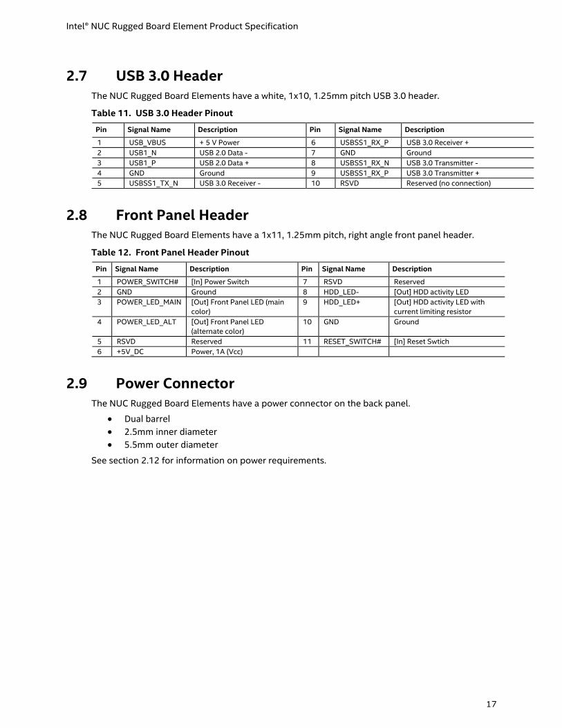
2.7 USB 3.0 Header The NUC Rugged Board Elements have a white, 1x10, 1.25mm pitch USB 3.0 header.
Table 11. USB 3.0 Header Pinout
Pin Signal Name Description Pin Signal Name Description
1 USB_VBUS + 5 V Power 6 USBSS1_RX_P USB 3.0 Receiver +
2 USB1_N USB 2.0 Data - 7 GND Ground
3 USB1_P USB 2.0 Data + 8 USBSS1_RX_N USB 3.0 Transmitter -
4 GND Ground 9 USBSS1_RX_P USB 3.0 Transmitter +
5 USBSS1_TX_N USB 3.0 Receiver - 10 RSVD Reserved (no connection)
2.8 Front Panel Header The NUC Rugged Board Elements have a 1x11, 1.25mm pitch, right angle front panel header.
Table 12. Front Panel Header Pinout
Pin Signal Name Description Pin Signal Name Description
1 POWER_SWITCH# [In] Power Switch 7 RSVD Reserved
2 GND Ground 8 HDD_LED- [Out] HDD activity LED
3 POWER_LED_MAIN [Out] Front Panel LED (main
color)
9 HDD_LED+ [Out] HDD activity LED with
current limiting resistor
4 POWER_LED_ALT [Out] Front Panel LED
(alternate color)
10 GND Ground
5 RSVD Reserved 11 RESET_SWITCH# [In] Reset Swtich
6 +5V_DC Power, 1A (Vcc)
2.9 Power Connector The NUC Rugged Board Elements have a power connector on the back panel.
• Dual barrel
• 2.5mm inner diameter
• 5.5mm outer diameter
See section 2.12 for information on power requirements.

Intel® NUC Rugged Board Element Product Specification
18
2.10 Embedded DisplayPort Connector The NUC Rugged Board Element CMCB1ABA has a 1x40, 0.5mm pitch, right angled Embedded
DisplayPort (eDP) connector.
Table 13. eDP Connector Pinout
Pin Signal Name Description
1 NC - RESERVED Reserved for LCD manufacturer’s use
2 H_GND High Speed Ground
3 Lane3_N Complement Signal Link Lane 3
4 Lane3_P True Signal Link Lane 3
5 H_GND High Speed Ground
6 Lane2_N Complement Signal Link Lane 2
7 Lane2_P True Signal Link Lane 2
8 H_GND High Speed Ground
9 Lane1_N Complement Signal Link Lane 1
10 Lane1_P True Signal Link Lane 1
11 H_GND High Speed Ground
12 Lane0_N Complement Signal Link Lane 0
13 Lane0_P True Signal Link Lane 0
14 H_GND High Speed Ground
15 AUX_CH_P True Signal Auxiliary Channel
16 AUX_CH_N Complement Signal Auxiliary Channel
17 H_GND High Speed Ground
18 LCD_VCC LCD logic and driver power (Vcc3)
19 LCD_VCC LCD logic and driver power (Vcc3)
20 LCD_VCC LCD logic and driver power (Vcc3)
21 LCD_VCC LCD logic and driver power (Vcc3)
22 NC LCD Panel Self-Test Enable (Optional)
23 LCD_GND LCD logic and driver ground
24 LCD_GND LCD logic and driver ground
25 LCD_GND LCD logic and driver ground
26 LCD_GND LCD logic and driver ground
27 HPD HPD signal pin
28 BL_GND Backlight ground
29 BL_GND Backlight ground
30 BL_GND Backlight ground
31 BL_GND Backlight ground
32 BL_ENABLE Backlight On/0ff
33 BL_PWM_DIM PWM dimming control signal
34 NC - RESERVED Reserved for LCD manufacturer’s use
35 NC - RESERVED Reserved for LCD manufacturer’s use
36 BL_PWR Backlight power (+Vin)
37 BL_PWR Backlight power (+Vin)
38 BL_PWR Backlight power (+Vin)
39 BL_PWR Backlight power (+Vin)
40 NC - RESERVED RESERVED for LCD manufacturer’s use

Intel® NUC Rugged Board Element Product Specification
19
2.11 Display Emulation The Intel® NUC Rugged Board Element supports emulation of displays using the HDMI ports so
that the system may be remotely accessed in a headless configuration or be capable of tolerating
display connectivity interruptions without the operating system redetecting and rearranging the
overall display layout. The display emulation feature may be enabled in Intel® NUC Compute
Element BIOS Setup (Advanced → Video → “Display Emulation” drop down menu) with the
following options:
• “No display emulation” (default selection): the system operates normally.
• “Virtual display emulation”: provides a 1280x1024 virtual display when no displays are connected to the system and provides an additional 1280x1024 virtual display if one display is attached to the system. If two display are attached to the system these displays will be enabled and no virtual displays will be provided.
• “Persistent display emulation”: emulates that both displays are always connected to the system no matter their actual connection status. The EDID information from each display will remain programmed through S3, S4, and S5 power states until the feature is disabled or a power cycle event (G3 global state) occurs.
• When “Persistent display emulation” is enabled another drop-down menu (“Inconsistent Display Device”) will become visible that allows the user to select the behavior of the system when the display device EDID is inconsistent with the EDID stored by the system.
▪ “Block boot” (default selection): the BIOS will display a warning message with options and will wait indefinitely for a user selection.
▪ “Countdown”: the BIOS will display a warning message with options and will wait 10 seconds before booting.
NOTE
“Persistent display emulation” is not compatible with HDCP 2.2 displays.
When using “Persistent display emulation” it would be expected behavior for the system not to
properly drive displays different than those connected when the feature was enabled, as the EDID
parameters of the initially connected displays are still being driven by the system. A power cycle
(AC power loss) is required to retrain the system with a different display configuration.
Intel® NUC Rugged Board Element Product Specification
20
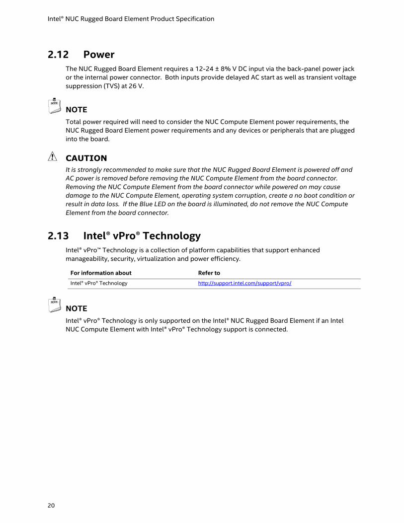
2.12 Power The NUC Rugged Board Element requires a 12-24 ± 8% V DC input via the back-panel power jack
or the internal power connector. Both inputs provide delayed AC start as well as transient voltage
suppression (TVS) at 26 V.
NOTE
Total power required will need to consider the NUC Compute Element power requirements, the
NUC Rugged Board Element power requirements and any devices or peripherals that are plugged
into the board.
CAUTION
It is strongly recommended to make sure that the NUC Rugged Board Element is powered off and
AC power is removed before removing the NUC Compute Element from the board connector.
Removing the NUC Compute Element from the board connector while powered on may cause
damage to the NUC Compute Element, operating system corruption, create a no boot condition or
result in data loss. If the Blue LED on the board is illuminated, do not remove the NUC Compute
Element from the board connector.
2.13 Intel® vPro® Technology Intel® vPro™ Technology is a collection of platform capabilities that support enhanced
manageability, security, virtualization and power efficiency.
For information about Refer to
Intel® vPro® Technology http://support.intel.com/support/vpro/
NOTE
Intel® vPro® Technology is only supported on the Intel® NUC Rugged Board Element if an Intel
NUC Compute Element with Intel® vPro® Technology support is connected.

Intel® NUC Rugged Board Element Product Specification
21
2.14 Wireless Enable/Disable Jumper
CAUTION
Do not change the switch with the power on. Always turn off the power and unplug the power cord
from the carrier board before changing a switch setting. Otherwise, the board could be damaged.
The jumper position determines whether the wireless module on the NUC Compute Element is enabled
or disabled. See Figure 8 for the location of the jumper. Table 14 describes the jumper settings.
Figure 8. Wireless Enable/Disable Jumper Location
Table 14. Wireless Enable/Disable Jumper Settings
Function/Mode Jumper Setting Configuration
Enable 1-2 Wireless and Bluetooth will be enabled on the NUC Rugged Compute Element
Disable 2-3 Wireless and Bluetooth will be disabled on the NUC Rugged Compute Element

Intel® NUC Rugged Board Element Product Specification
22
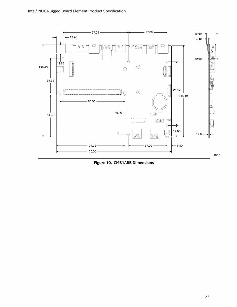
Mechanical The following figures illustrate the mechanical form factor for the Intel® NUC Rugged Board
Elements. Dimensions are given in millimeters (mm).
Figure 9. CMB1ABA Dimensions
Intel® NUC Rugged Board Element Product Specification
23
Figure 10. CMB1ABB Dimensions

Intel® NUC Rugged Board Element Product Specification
24
Figure 11. CMB1ABC Dimensions
Intel® NUC Rugged Board Element Product Specification
25
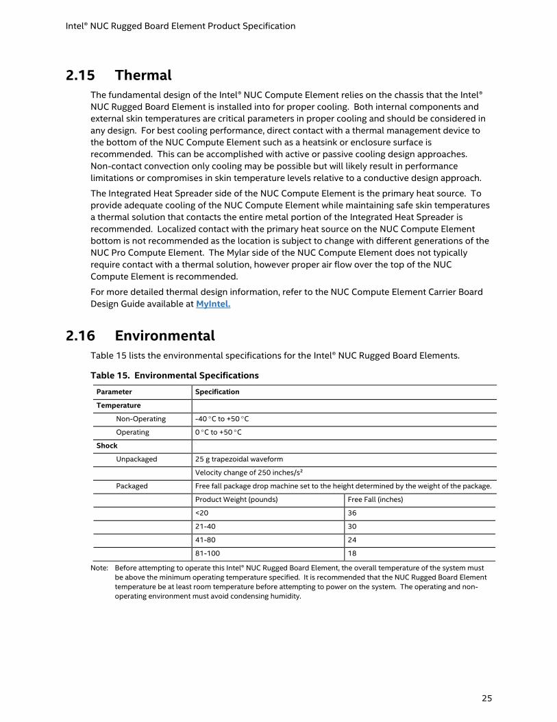
2.15 Thermal The fundamental design of the Intel® NUC Compute Element relies on the chassis that the Intel®
NUC Rugged Board Element is installed into for proper cooling. Both internal components and
external skin temperatures are critical parameters in proper cooling and should be considered in
any design. For best cooling performance, direct contact with a thermal management device to
the bottom of the NUC Compute Element such as a heatsink or enclosure surface is
recommended. This can be accomplished with active or passive cooling design approaches.
Non-contact convection only cooling may be possible but will likely result in performance
limitations or compromises in skin temperature levels relative to a conductive design approach.
The Integrated Heat Spreader side of the NUC Compute Element is the primary heat source. To
provide adequate cooling of the NUC Compute Element while maintaining safe skin temperatures
a thermal solution that contacts the entire metal portion of the Integrated Heat Spreader is
recommended. Localized contact with the primary heat source on the NUC Compute Element
bottom is not recommended as the location is subject to change with different generations of the
NUC Pro Compute Element. The Mylar side of the NUC Compute Element does not typically
require contact with a thermal solution, however proper air flow over the top of the NUC
Compute Element is recommended.
For more detailed thermal design information, refer to the NUC Compute Element Carrier Board
Design Guide available at MyIntel.
2.16 Environmental Table 15 lists the environmental specifications for the Intel® NUC Rugged Board Elements.
Table 15. Environmental Specifications
Parameter Specification
Temperature
Non-Operating -40 C to +50 C
Operating 0 C to +50 C
Shock
Unpackaged 25 g trapezoidal waveform
Velocity change of 250 inches/s²
Packaged Free fall package drop machine set to the height determined by the weight of the package.
Product Weight (pounds) Free Fall (inches)
<20 36
21-40 30
41-80 24
81-100 18
Note: Before attempting to operate this Intel® NUC Rugged Board Element, the overall temperature of the system must
be above the minimum operating temperature specified. It is recommended that the NUC Rugged Board Element
temperature be at least room temperature before attempting to power on the system. The operating and non-
operating environment must avoid condensing humidity.
Intel® NUC Rugged Board Element Product Specification
26
3 Characterized Errata
This section of the document communicates product Errata for the Intel® NUC Rugged Board
Element CMB1ABA, CMB1ABB and CMB1ABC.
Errata are design defects or deviations from current published specifications for a given product.
Published errata may or may not be corrected. Hardware and software designed to be used with
any given processor stepping must assume that all errata documented for that process stepping
are present on all devices.
There are no known characterized errata.


