
INTERCONNECTION OF IP/MPLS NETWORKS
THROUGH ATM AND OPTICAL BACKBONES
USING PNNI PROTOCOLS
SERGIO SÁNCHEZ LÓPEZ
2003
UPCUPCUPC
UNIVERSITAT POLITÈCNICA
DE CATALUNYA

Ph.D. Student: Sergio Sánchez-López
Advisor: Dr. Josep Solé-Pareta
Co-Advisor: Prof. Jordi Domingo-Pascual
A THESIS PRESENTED TO THE UNIVERSITAT POLITÈCNICA DE CATALUNYA
IN FULFILMENT OF THE REQUIREMENTS FOR THE DEGREE OF
Doctor en Enginyeria de Telecomunicació
Interconnection of IP/MPLS Networks through ATM and
Optical Backbones using PNNI Protocols
Department of Computer Architecture
Universitat Politècnica de Catalunya
June 2003
UPCUPCUPC
UNIVERSITAT POLITÈCNICA
DE CATALUNYA


Agradecimientos/Acknowledgements
En primer lugar me gustaría agradecer a Josep Solé y a Jordi Domingo el haber depositado
su confianza en mí y haber dirigido esta tesis. Gracias por introducirme en el apasionante
mundo de la investigación y por enseñarme a trabajar dentro de proyectos internacionales
que han hecho que el trabajo realizado en esta tesis tuviera una proyección exterior.
También agradecer a todos los miembros del grupo de investigación su constante apoyo y
colaboración que han hecho que los momentos difíciles fueran mucho más soportables.
Al departamento de Arquitectura de Computadores por reconocer el esfuerzo que los
profesores de Vilanova debemos hacer en el campo de la investigación y por ofrecernos todas
las facilidades de que dispone para que nosotros también estemos a la altura del resto de
investigadores del departamento.
A mi gran amigo y colega Xavi. Para él no es un agradecimiento sino un total reconocimiento
tanto a su forma de ser como de trabajar. Desde hace más de catorce años que formamos un
tándem del cual él es el motor. Gracias a su iniciativa, empuje y en especial a su inagotable
espíritu de superación, mi trabajo, tanto de profesor como de investigador, se ha convertido
en una de las tareas cotidianas más gratificantes que una persona puede desear. De hecho, y
para ser justos, su nombre debería aparecer junto al mío en la portada de esta tesis.
Pero esta tesis nunca hubiera llegado a su final sino hubiera sido por Cristina. Ella es la que
me ha enseñado a superar los momentos de flaqueza, me ha enseñado a convertir los grandes
problemas en meras preocupaciones y sobre todo me ha dado toda la energía que uno
necesita para realizar un trabajo de esta envergadura. Con ella he podido celebrar los logros
conseguidos, compartir las desesperaciones y enfrentarme a cualquier reto que se ha
presentado, siempre con la tranquilidad que da tener a una mujer tan excepcional a mi lado.
Sólo espero saber estar a su altura en los momentos en que ella me necesite.
.


Resumen
Las redes de transporte se mueven hacia un modelo de redes formadas por routers IP/MPLS (Internet
Protocol/Multiprotocol Laebel Switching) de altas prestaciones interconectadas a través redes
troncales inteligentes. Actualmente la tecnología ATM está ampliamente desarrollada en dichas redes
troncales que utilizan los protocolos PNNI (Private Network-Network Interface) como plano de
control. En cambio la interoperabilidad entre redes IP/MPLS a través de redes PNNI-ATM es todavía
un aspecto en proceso de estudio. Por otro lado, la tendencia futura de Internet es ir hacia redes
troncales completamente ópticas con capacidad automática de conmutación para permitir un mejor
tratamiento del tráfico solicitado. Debido al esfuerzo realizado por los organismos de estandarización
sobre redes ópticas, se ha definido un primer modelo de red llamado ASON (Automatic Switched
Optical Network). Mientras las redes actuales basadas en SDH (Synchronous Digital Hierarchy)
ofrecen sólo capacidad de transporte, la futura ASON permitirá el establecimiento y la liberación de
canales ópticos de forma automática. Un aspecto clave para conseguir esta funcionalidad es la
definición de un plano de control óptico que será el responsable de realizar las funciones de
señalización y encaminamiento.
Diferentes estudios han sido realizados para conseguir interoperabilidad entre redes con tecnología
IP/MPLS y ATM basados esencialmente en la distribución de información de señalización MPLS a
través de una red troncal ATM. Una de las soluciones planteadas se basa en la utilización sobre cada
uno de los conmutadores ATM, un dispositivo capaz de procesar información MPLS, llamado LSR
(Label Switched Router). Otra, en cambio, propone el establecimiento de un camino MPLS, llamado
LSP (Label Switched Path), encapsulado dentro de un camino ATM o VPC (Virtual Path Connection).
Ambas soluciones presentan el inconveniente de utilizar un tiempo de establecimiento demasiado
elevado.
Respecto al plano de control para ASON, decir que una de las opciones propuestas es la de utilizar el
GMPLS (Generalizad MPLS) que es una extensión del modelo MPLS con ingeniería de tráfico. Sin
embargo, recientemente se ha iniciado un debate en lo foros de estandarización sobre la posibilidad
de utilizar el PNNI como plano de control en ASON. Los argumentos que justifican esta opción son
que el PNNI, después de unas apropiadas modificaciones, puede ser adecuado para ASON y lleva
años funcionando en muchas de las actuales redes de transporte.
Esta tesis está basada en el estudio de los dos casos mencionados anteriormente. El primero caso es
el de dos redes IP/MPLS conectadas a través de una red troncal ATM la cual utiliza el PNNI como
plano de control. En este contexto, el objetivo principal será el de definir un mecanismo rápido de
establecimiento de la conexión que proporcione los parámetros requeridos de calidad deservicio entre

dos nodos pertenecientes a cada una de las redes IP/MPLS. Para conseguirlo se realizarán las
modificaciones pertinentes en el PNNI y se añadirán nuevos elementos de señalización.
El segundo caso consiste en interconectar dos redes IP/MPLS a través de una red troncal óptica. En
primer lugar se adaptará el PNNI para conseguir un protocolo de encaminamiento para ASON con el
fin de proporcionar un establecimiento rápido de la conexión en un entorno IP/MPLS-ASON.
Finalmente, se definirá un plano de control, llamado O-PNNI (Optical PNNI) basado en la
adaptación total del ATM PNNI a redes ASON. Esta tesis finaliza con un análisis de las ventajas y
desventajas de los modelos GMPLS y O-PNNI como planos de control en ASON.
i
Table of contents
List of Figures..........................................................................................................................................v
List of Tables .........................................................................................................................................vii
Abbreviations..........................................................................................................................................ix
Abstract...................................................................................................................................................xi
PART I INTRODUCTION......................................................................................................................1
1. Introduction.................................................................................................................................3
1.1. Towards a new Internet Architecture ........................................................................................3
1.2. Transport Networks – State of the Art ......................................................................................5
1.3. Organization and Goals of this Thesis.......................................................................................6
2. Evolution of the Technologies for Transport Networks .............................................................9
2.1. Optical Layer.............................................................................................................................9
2.2. “Electrical” Layer....................................................................................................................10
2.2.1. IP/MPLS Layer ........................................................................................................................... 10
2.2.2. ATM Layer.................................................................................................................................. 14
2.2.3. SDH Layer................................................................................................................................... 15
2.2.4. Gigabit Ethernet.......................................................................................................................... 17
3. ATM PNNI Protocols ...............................................................................................................21
3.1. Introduction .............................................................................................................................21
3.2. PNNI Routing..........................................................................................................................21
3.3. PNNI Signalling ......................................................................................................................26
3.4. PNNI Addressing ....................................................................................................................29
PART II INTERCONNECTION OF IP/MPLS-ATM NETWORKS USING PNNI............................31
4. MPLS over ATM: State of the Art and Problem Definition.....................................................33
4.1. Integrating MPLS with IP and ATM.......................................................................................33
4.2. Distribution of MPLS Information through an ATM Network...............................................36

ii
4.3. Problem Definition ..................................................................................................................39
5. PNNI Adaptation for LSP Set-up in MPLS-ATM Integrated Environments ...........................41
5.1. MPLS-ATM Integration based on PNNI ................................................................................41
5.2. Fast LSP set-up Mechanism ....................................................................................................43
5.3. Performance Evaluation and Numerical Results.....................................................................46
5.3.1. Evaluation of the fast Mechanism to set up an LSP .............................................................. 46
5.3.2. Evaluation of the need for Providing QoS Requirements for the fast Mechanism to set up LSP.. 51
6. A Fast Mechanism to Establish an LSP with QoS Requirements.............................................55
6.1. QoS Mechanism based on an Aggregated Traffic Engineering Database (ATED) ................58
6.2. Performance evaluation and numerical results........................................................................62
PART III PNNI BASED CONTROL PLANE FOR ASON..................................................................67
7. Recommendations for ASON and PNNI Standard Features ....................................................69
7.1. Introduction .............................................................................................................................69
7.2. ITU-T Recommendations for ASON ......................................................................................70
7.2.1. ASON Control Plane Components .......................................................................................... 70
7.2.2. Routing......................................................................................................................................... 72
7.2.3. Addressing................................................................................................................................... 74
7.3. PNNI Standard Features..........................................................................................................75
8. PONNI: A Routing Protocol for ASON ...................................................................................77
8.1. Introduction .............................................................................................................................77
8.2. Hierarchical Structure..............................................................................................................79
8.3. Network Information Dissemination.......................................................................................81
8.4. Hierarchical QoS Routing in Automatic Switched Optical Networks (ASONs) ....................83
8.4.1. Aggregation Schemes for PONNI............................................................................................ 84
8.4.2. Update Policy for PONNI ......................................................................................................... 88
8.4.3. Routing Algorithm for PONNI................................................................................................. 88
8.4.4. Example of Aggregation............................................................................................................ 90
8.5. Distribution of Non-optical Information across the ASON.....................................................93

iii
8.6. Case Study...............................................................................................................................95
9. Optical PNNI (O-PNNI) Control Plane ....................................................................................99
9.1. Introduction .............................................................................................................................99
9.2. O-PNNI Routing....................................................................................................................100
9.3. O-PNNI Signalling................................................................................................................101
9.3.1. ASON Requirements Directly Supported by PNNI Signalling ......................................... 101
9.3.2. ASON Requirements Demanding PNNI Signalling Adaptation ....................................... 103
9.3.3. Integrating Client Networks with O-PNNI Signalling ........................................................ 107
9.4. O-PNNI Addressing ..............................................................................................................110
9.5. O-PNNI vs. GMPLS: pros and cons......................................................................................112
PART IV CONCLUSIONS AND FUTURE WORK..........................................................................117
10. Summary and Conclusions .....................................................................................................119
11. Future Work............................................................................................................................121
References............................................................................................................................................123
APPENDIX: LIST OF PUBLICATIONS AND PROJECTS..............................................................127

v
List of Figures
Fig. 1: Example of the transport network architecture – current status ...................................................5
Fig. 2: Traditional Transport Network Scenario......................................................................................6
Fig. 3: Converged Network......................................................................................................................6
Fig. 4. An example of a complete PNNI hierarchically configured network ........................................23
Fig. 5. PNNI signalling message exchange during call set-up and release............................................29
Fig. 6. E. 164 addressing format ............................................................................................................30
Fig. 7. Peer Model (left) and Overlay Model (right) .............................................................................34
Fig. 8. Augmented Model ......................................................................................................................35
Fig. 9. Label Distribution between ATM-LSRs ....................................................................................36
Fig. 10. Tunnelling through ATM .........................................................................................................37
Fig. 11. Communicating the VCID within ATM signalling messages ..................................................38
Fig. 12. Border Router Architecture ......................................................................................................42
Fig. 13. PAR MPLS services IG format ................................................................................................42
Fig. 14. Network topology scenario.......................................................................................................44
Fig. 15. BR Topology Databases ...........................................................................................................44
Fig. 16. New Generic Identifier Element...............................................................................................45
Fig. 17. Network topology with the ATM backbone as an MPLS node................................................46
Fig. 18. Network Topology scenario .....................................................................................................51
Fig. 19. Speed-up (a) Fast LSP/LSR and (b) Fast LSP/RSVP TUNNEL..............................................50
Fig. 20. Packet size for (a) BW2= 34Mbps and (b) BW2= 2Mbps.........................................................50
Fig. 21. End-to-end LSP Blocking Ratio for range 1.............................................................................53
Fig. 22. End-to-end LSP Blocking Ratio for range 2.............................................................................53
Fig. 23. Generic Identifier with BW ......................................................................................................57
Fig. 24. Steps for an FMA scheme ........................................................................................................59
Fig. 25. Steps for an ASA scheme .........................................................................................................60
Fig. 26. PAR MPLS ATED Services definition IG ...............................................................................61
Fig. 27. Comparison between FMA and ASA ATED size ....................................................................65

vi
Fig. 28 LSP blocking ratio due to the ATED inaccuracy ......................................................................66
Fig. 29. Hierarchical Addressing Format...............................................................................................80
Fig. 30: A Possible Hierarchical Structure ............................................................................................81
Fig. 31. Hierarchical QoS Routing ........................................................................................................91
Fig. 32. IP/MPLS-Optical backbone scenario .......................................................................................94
Fig. 33. Topology Databases .................................................................................................................94
Fig. 34. Hypothetical hierarchical structure based on the Pan-European Network topology ................95
Fig. 35. Scalability from flat network to a hierarchical network (Data) ................................................96
Fig. 36. Scalability from flat network to a hierarchical network (Time) ...............................................97
Fig. 37: ASON Connection Controller component..............................................................................101
Fig. 38: Switching system architecture in PNNI..................................................................................102
Fig. 39: Generic Identifier Transport Element.....................................................................................104
vii
List of Tables
Table 1. Topology States Parameters.....................................................................................................24
Table 2. PAR Information Group ..........................................................................................................26
Table 3. PNNI standard features and ASON requirements ...................................................................75
Table 4: POTSE information .................................................................................................................82
Table 5: Topology/available resource database in X1...........................................................................91
Table 6: Topology/available resource database in X2...........................................................................92
Table 7. PONNI routing stability...........................................................................................................96
Table 8: Two new O-PNNI messages..................................................................................................105
Table 9: Comparison of GMPLS and O-PNNI....................................................................................116

ix
AbbreviationsAAL ATM Adaptation Layer ACAC Actual Call Admission Control ADM Add and Drop Multiplexing AFI Authority and Format Identifier APRoPs ATM PNNI Routing Protocol
Simulator ASON Automatic Switched Optical
Network ASTN Automatic Switched Transport
Network ATM Asynchronous Transfer Mode ATMF ATM Forum BBOR BYPASS Based Optical Routing BOX Border OXC BR Border Router Bw Bandwidth CAC Call Admission Control CC Connection Controller CCI Connection Controller Interface CoS Class of Service CR Constraint-based Routing CSPF Constrained Shortest Path First CUG Closed User Groups DSP Domain Specific Part DWDM Dense WDM DXC Digital Coss-Connect E-NNI External Network-to-Network
Interface ERO Explicit Routing Object ESI End System Identifier GCAC Generic Connection Admission
Control GIT Generic Identifier Element GMPLS Generalised Multi-Protocol Label
Switching GoS Grade of Service IDI Initial Domain Identifier I-NNI Internal Network-to-Network
Interface IETF Internet Engineering Task Force IP Internet Protocol IPv4 Internet Protocol version 4 Ipv6 Internet Protocol version 6 ISO International Organization for
Standardization ITU-T International Telecommunication
Union-Telecommunication Sector IWU Internetworking Signalling Unit LC-ATM
Label-switched Controlled ATM
LDP Label Distribution Protocol LRMA Link Resource Manager-A
LRMZ Link Resource Manager-Z LSN LSP
Logical Subnetwork Node Label Switched Path
LSR Label Switched Routers LSRv Virtual LSR MPLS MultiProtocol Label Switching ND Network Domain NMS NRBw
Network Management System No Requested Bw
NSAP Network Service Access Point OAM Organization, Administration
and Maintenance OADM Optical ADM Och Optical channel ODXC Optical DXC OIF Optical Internetworking Forum OTN Optical Transport Network OXC Optical Cross-Connect PAR PNNI Augmented Routing PC Protocol Controller PDH Plesiochronous Digital Hierarchy PG Peer Group PGL Peer Group Leader PNNI Private Network-Network Interface POAR PNNI Optical Augmented Routing POTSE PNNI Optical Topology State
Element POTSP PNNI Optical Topology State
Packet PPAR Proxy PAR PPP PTSE
Point-to-Point Protocol PNNI Topology State Element
PTSP PNNI Topology State Packet PVC Permanent Virtual Circuit PVCC Permanent Virtual Circuit
Connection PVPC Permanent Virtual Path Connection QoS Quality of Service RAIG Resource Available Information
Group RBw Requested Bw RC Routing Controller RSVP Resource Reservation Protocol SDH Synchronous Digital hierarchy SID Subnetwork Identifier SL Subnetwork Leader SNC Subnetwork Connection SNP Subnetwork Path SNPP Subnetwork Termination Point
Pool SPF Shortest Path First SPVC Soft-Permanent Virtual Connection

x
SSCOP Service-Specific Connection- Oriented Protocol
STM Synchronous Transfer Mode SVC Switched Virtual Circuit TDM Time-Division Multiplexing TE Traffic Engineering TED Traffic Engineering Database TLV Type Length Value TP Traffic Policing UNI User Network Interface VC Virtual Circuit VCI Virtual Circuit Identifier VCID Virtual Connection Identifier VPC Virtual Path Connection VPI Virtual Path Identifier VPN Virtual Private Network WSP Widest-Shortest Path WDM Wavelength Division Multiplexing

xi
Abstract
Transport networks are moving towards a model of high performance (Internet
Protocol/Multiprotocol Label Switching) IP/MPLS routers interconnected through intelligent
backbones. Currently, Asynchronous Transfer Mode(ATM) technology is widely deployed in the
backbones and the Private Network-Network Interface (PNNI) protocols are used as a control
plane, but interoperability between IP/MPLS networks interconnected through a PNNI ATM
backbone is still an open issue. On the other hand, the future Internet is gravitating towards
optical backbones with automatic switching capabilities in order to cope with the increasing
growth of Internet traffic demands. Because of the standardisation effort on optical networking,
a preliminary model has recently been defined: the Automatic Switched Optical Network
(ASON). While current SDH networks give only transport capacity, future ASONs will allow
dynamic set-up and tear-down of optical channels. A key issue to resolve to achieve this
functionality is to define a control plane, which is responsible for the routing and signalling
process.
Different approaches have been considered for providing interoperability between MPLS and
ATM technologies. The key problem is the distribution of MPLS signalling information through
an ATM backbone, which has been solved either using Label Switched Routers (LSRs) on top of
the ATM switches or tunnelling a Label Switched Path (LSP) through an ATM Virtual Path
Connection (VPC). The main drawbacks of these solutions are, in the former, that it is
necessary to add an IP/MPLS router over each ATM switch, and in the latter, the encapsulation
and transport of the signalling information through the ATM cloud. Moreover, in both
approaches the set-up time is high.
The Generalised Multi-protocol Label Switching (GMPLS) protocol, which is considered an
extension of the MPLS traffic engineering control plane model, is widely agreed to be the right
choice to implement the ASON control plane. Nevertheless, discussions about the potential use
of PNNI in ASON have recently started in the standardisation forums. There are two main
reasons for this: first, PNNI is expected (after appropriate modifications) to be suitable for
ASONs; and second, PNNI is mature and widely distributed in today’s transport networks.
This thesis deals with both above mentioned cases: 1) the case of two IP/MPLS networks
interconnected through a backbone, assuming MPLS is the mechanism to provide Traffic
Engineering in the IP networks, and ATM technology in the backbone with a control plane
based on the PNNI protocols. Here, the main goal is to define a fast mechanism to set up an

end-to-end LSP, with the required Quality of Service (QoS), between two LSRs belonging to
different IP/MPLS domains. In order to achieve these objectives, new PNNI elements are
defined and evaluated. 2) The case of IP/MPLS networks interconnected through ASON
backbones. Here, aiming to provide fast end-to-end LSP set-up in IP/MPLS-ASON
environments, we make an adaptation of the ATM-PNNI routing protocol to cope with the
routing functions in ASON networks. Finally, we define an Optical PNNI (O-PNNI) protocol as
an adaptation of the well known ATM-PNNI protocols, and analyse the potential use of both the
defined O-PNNI and the GMPLS model, looking at the pros and cons of each approach.

1
PART I
INTRODUCTION
This part introduces the context of this thesis and reviews the key issues that are
impacting on the network evolution, the emerging applications and network
requirements that drive the transport network developments. Moreover, it contains a
brief explanation of the PNNI protocols, which will be the key issue of this thesis.


Introduction 3
1. Introduction
1.1. Towards a new Internet Architecture
The exponential growth of real-time multimedia traffic is directing network evolution
towards transport infrastructures enabling the provisioning of connections with certain
performance guarantees, such as Quality of Service (QoS) requirements (high
bandwidth, low end-to-end delay, low delay jitter and minimal losses). Real-time
applications require the utilization of real-time channels, which must be set up with
specific traffic characteristics and QoS requirements. The time required to set up an
end-to-end real-time channel is one of the fundamental metrics to be taken into
consideration in real-time applications [41].
In the Internet, these transport networks are moving towards a model of high
performance Internet Protocol/MultiProtocol Label Switching (IP/MPLS) routers
interconnected through intelligent backbones, which directly provide an infrastructure
for new IP services that is compatible with existing IP services. An intelligent backbone
supports emerging requirements such as dynamic and rapid provisioning of connections,
automatic topology discovery, reactive Traffic Engineering (TE) and fast restoration. A
key issue to achieve these functionalities is the definition of a control plane responsible
for the routing and signalling processes. This control plane must be independent of the
other network control planes interconnected through the same backbone.

4 Chapter 1
Initially, ATM (Asynchronous Transfer Mode) networks were expected to replace the
current router-based Internet. Although this did not happen, ATM switches are widely
used in the core networks as a backbone technology. Therefore, the ATM Forum has
proposed the Private Network-Network interface (PNNI) [1] as a backbone control
plane, which consists of a routing protocol and a signalling protocol. A typical scenario
in the current Internet is the case of two IP/MPLS networks interconnected through a
PNNI-ATM backbone. In such a scenario, the interoperability between the MPLS and
ATM technologies required to achieve MPLS connectivity across the ATM backbone is
still an open issue. In particular, the problem is how to set up a fast end-to-end Label
Switched Path (LSP) with QoS guarantees between two Label Switched Routers (LSRs)
located in different MPLS domains in an IP/MPLS-ATM environment.
Different approaches have been considered for providing interoperability between
MPLS and ATM technologies. The key problem is the distribution of MPLS
information through an ATM backbone, which has been solved either using ATM-LSRs
on top of the ATM switches or tunnelling an LSP through an ATM Virtual Path
Connection (VPC). The main drawbacks of these solutions are, in the former, that it is
necessary to add an IP/MPLS router over each ATM switch, and in the latter, the
encapsulation and transport of the signalling information through the ATM cloud.
The future Internet is gravitating towards optical infrastructures with automatic
switching capabilities in order to cope with increasing Internet traffic demands. Because
of the standardisation effort on optical networking, a first model has recently been
approved: the Automatic Switched Optical Network (ASON) [2]. While current optical
networks only give transport capacity, the ASON dynamically sets up and tears down
optical channels. A key issue to achieve this functionality is the definition of a control
plane, which is responsible for the routing and signalling process. The Generalised
Multi-protocol Label Switching (GMPLS) protocol, which is considered an extension of
the MPLS Traffic Engineering control plane model, is widely agreed to be the right
choice to implement the ASON control plane. Nevertheless, discussions about the
potential use of PNNI in ASON have recently started in the standardisation forums for
two main reasons: first, PNNI is expected (after some modifications) to be suitable for
Introduction 5
ASONs; and second, PNNI is mature and widely distributed in today’s transport
networks.
1.2. Transport Networks – State of the Art
This Subsection reviews the key issues that are impacting on the network evolution, the
emerging applications and network requirements that drive the transport network (TN)
developments [27].
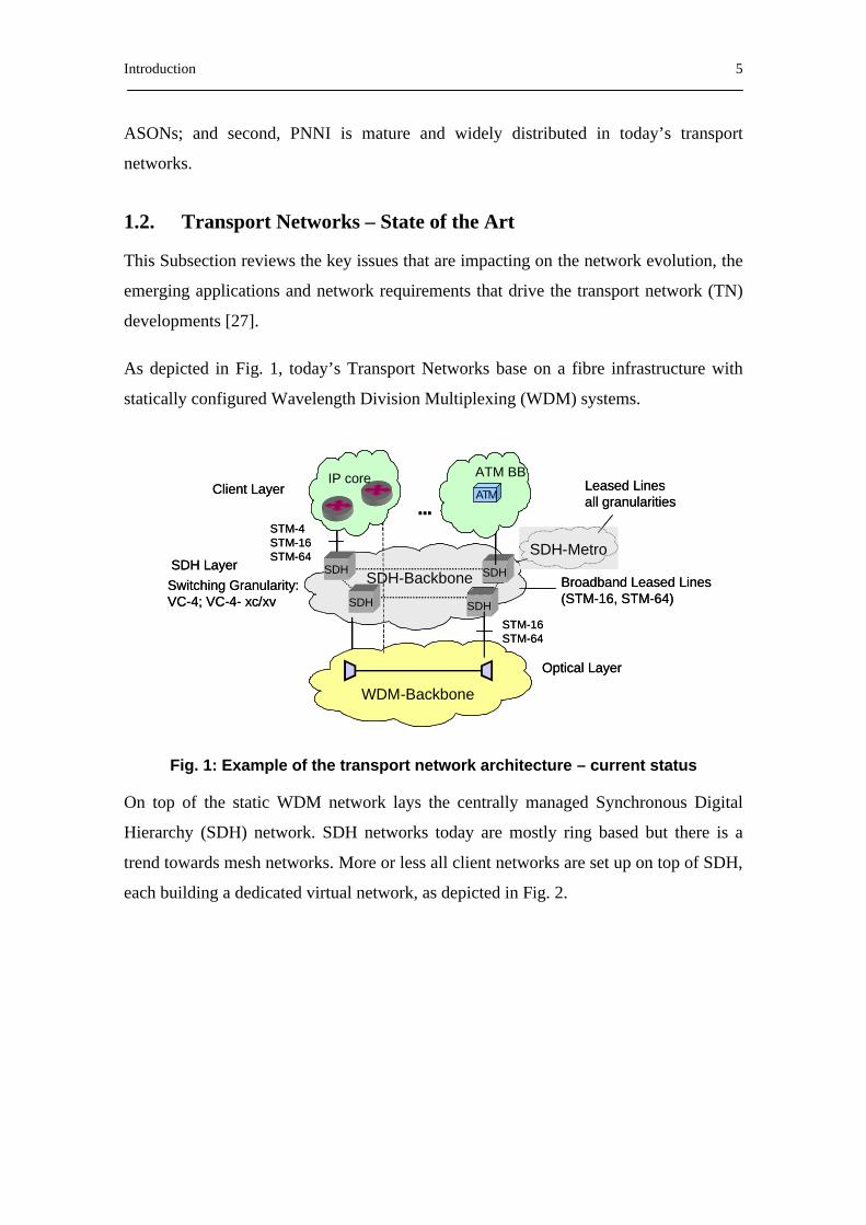
As depicted in Fig. 1, today’s Transport Networks base on a fibre infrastructure with
statically configured Wavelength Division Multiplexing (WDM) systems.
Fig. 1: Example of the transport network architecture – current status
On top of the static WDM network lays the centrally managed Synchronous Digital
Hierarchy (SDH) network. SDH networks today are mostly ring based but there is a
trend towards mesh networks. More or less all client networks are set up on top of SDH,
each building a dedicated virtual network, as depicted in Fig. 2.
SDH-Backbone
STM-16 STM-64
Switching Granularity: VC-4; VC-4- xc/xv
STM-4STM-16 STM-64
...Client Layer
Optical Layer
SDH
SDH
SDH
SDH
ATM
WDM-Backbone
IP core ATM BB
Broadband Leased Lines(STM-16, STM-64)
SDH LayerSDH-Metro
Leased Linesall granularities
SDH-Backbone
STM-16 STM-64
Switching Granularity: VC-4; VC-4- xc/xv
STM-4STM-16 STM-64
...Client Layer
Optical Layer
SDH
SDH
SDH
SDH
ATM
WDM-Backbone
IP core ATM BB
Broadband Leased Lines(STM-16, STM-64)
SDH LayerSDH-Metro
Leased Linesall granularities
6 Chapter 1
Fig. 2: Traditional Transport Network Scenario
The main clients of the TN are IP networks, connected with Synchronous Transfer
Mode-16 (STM-16) or STM-64 rates mostly. IP routers may be directly connected via
STM-16 and STM-64 static WDM connections, if they do not rely on SDH protection.
MPLS is being implemented in most operators’ IP backbones. Leased lines today are
mostly realized on SDH (2 Mbit/s or more). Other client networks like ATM are based
on the SDH network. LAN-LAN connections and VPNs very often use ATM networks
on top of SDH. With the introduction of MPLS in many TNs they are successively
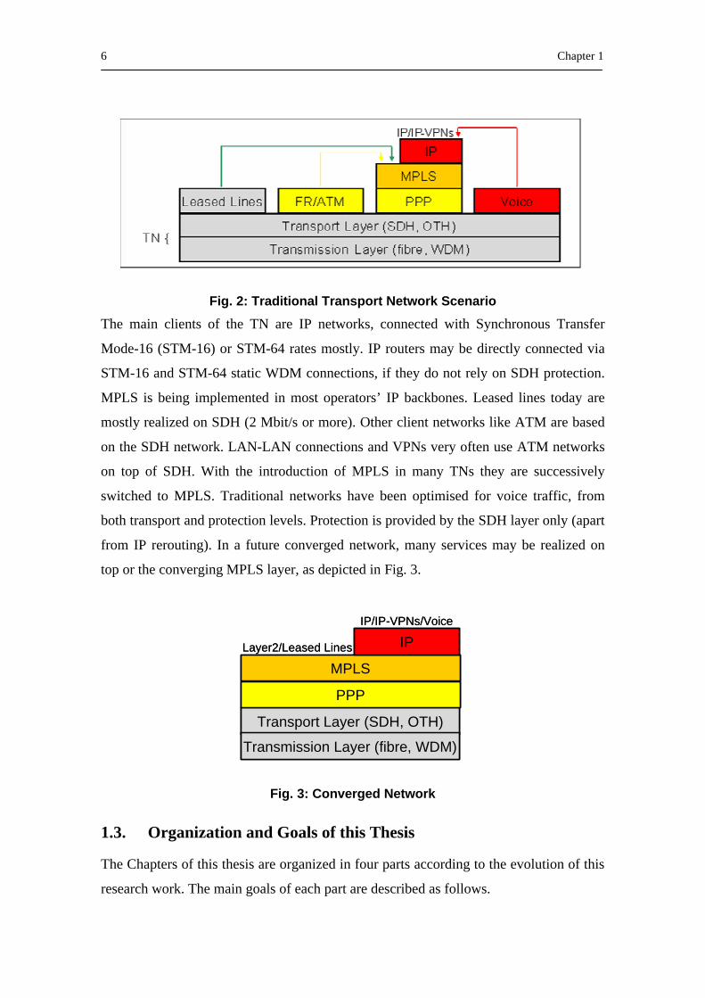
switched to MPLS. Traditional networks have been optimised for voice traffic, from
both transport and protection levels. Protection is provided by the SDH layer only (apart
from IP rerouting). In a future converged network, many services may be realized on
top or the converging MPLS layer, as depicted in Fig. 3.
Fig. 3: Converged Network
1.3. Organization and Goals of this Thesis
The Chapters of this thesis are organized in four parts according to the evolution of this
research work. The main goals of each part are described as follows.
Transport Layer (SDH, OTH)
Transmission Layer (fibre, WDM)
PPP
MPLS
IPIP/IP-VPNs/Voice
Layer2/Leased Lines
Transport Layer (SDH, OTH)
Transmission Layer (fibre, WDM)
PPP
MPLS
IPIP/IP-VPNs/Voice
Layer2/Leased Lines
Introduction 7
In Part I, Chapter 2 reviews the key issues that are impacting on the network evolution,
the emerging applications and network requirements that drive the transport network
developments. Chapter 3 briefly explains the PNNI protocols, which will be the key
issue of this thesis.
Part II tackles the association between IP/MPLS because of the fact that both
technologies are widely deployed and each has its potency. Chapter 4 presents the
existing solutions to transport MPLS signalling information across an ATM cloud and
expresses the problem of minimizing the end-to-end set-up time in an MPLS-ATM-
MPLS environment. Chapter 5 deals with a PNNI routing protocol based solution that
provides integration between IP/MPLS and ATM. Moreover, it addresses the problem
of minimizing the end-to-end setup time in the environment presented in Chapter 4.
Finally, Chapter 6 is devoted to apply the Traffic Engineering (TE) based routing
algorithms to the proposed fast set-up mechanism to reduce the congestion effects in the
different IP/MPLS domains.
Part III defines Optical PNNI (O-PNNI) as an adaptation of the ATM-PNNI protocols,
and analyses the potential usage of the O-PNNI and GMPLS models, looking at pros
and cons of each approach. The methodology adopted to enhance PNNI protocols
consist of reviewing PNNI, along with ASON recommendations, in order to determine
the set of PNNI features that require adaptation for supporting an ASON control plane
(Chapter 7). Having identified these features, we obtain and present the appropriate
solutions. Therefore, Chapter 8 adapts the PNNI routing protocol to the ASON
requirements. Finally, Chapter 9 presents an appropriately guidelines to adapt the ATM
PNNI protocols for supporting the control plane of ASONs.
Finally, Part IV summarizes the work carried out in this thesis, states its conclusions
and presents some of the future work.


Evolution of the Technologies for Transport Networks 9
2. Evolution of the Technologies for Transport Networks
2.1. Optical Layer
The recent advances in optical layer technology enable the architecture optimisation of
telecommunication transport networks. The spectacular progress of the capacity
aggregated by the fibre optic removed the bandwidth bottleneck in the core, regional
and metropolitan networks. Dense Wavelength Division Multiplexing (DWDM)
systems already installed by network operators offer up to 10/40 Gbps data rate per
optical carrier and 160 of carriers per fibre. Prognoses for next three to five years
promise several hundreds of lambdas and 3 to 6 Tbps aggregate transport capacity per
fibre.
Currently, the main effort of equipment vendors and network operators concerns the
architectural aspects of the optical layer. Introduction of optical switches, called Optical
Cross-Connect (OXC), and optical Add and Drop Multiplexing (ADM) (OADM) will
enable major cost reduction in overall networking due to minimised electronic signal
processing and opto-electronic conversions.
Network operators usually adapt progressive evolution scenarios for the optical layer. A
first step can be based on the introduction of integrated core switches, enabling signal
processing at both the electrical (digital) and optical layer. Integrated optical digital
10 Chapter 2
cross-connects (O-DXCs) would assure compatibility with the legacy networks and at
the same time would provide switching capability at the Optical Channel (OCh) layer,
various classes for network survivability and offer a feasible migration path from the
ring to mesh based topology for bandwidth use optimisation.
Constant progress in optical technology will bring to the market optical nodes with
enhanced functionality. The introduction of fast, tuneable lasers will enable all optical
reconfigurable (programmable) switches and ADMs.
The next step towards an OXC implementing distributed control plane specifications,
i.e. an automatically switched optical transport network would take place as soon as
such an evolution would become economically viable.
2.2. “Electrical” Layer
2.2.1. IP/MPLS Layer
In the traditional Level 3 forwarding paradigm, as a packet travels from one router to
the next, an independent forwarding decision is made at each hop. The IP network layer
header is analysed, and the next hop is chosen based on this analysis and on the
information contained in the routing table.
Multiprotocol Label Switching (MPLS) [8] provides a mechanism for engineering
network traffic patterns that is independent of routing tables. MPLS assigns short labels
to network packets that describe how to forward them through the network. In an MPLS
environment, the analysis of the packet header is performed just once, when a packet
enters an MPLS cloud. Then, the packet is assigned to a stream, which is identified by a
label, which is a short (20-bit), fixed-length value at the front of the packet. Labels are
used as lookup indexes into the label forwarding table. For each label, this table stores
forwarding information. Additional information can be associated with a label, such as
class-of-service (CoS) values that can be used to prioritise packet forwarding. MPLS is
independent of any routing protocol.
MPLS provides functional traffic engineering (TE) capabilities required to implement
policies that facilitate efficient and reliable network operations in an MPLS domain.
Evolution of the Technologies for Transport Networks 11
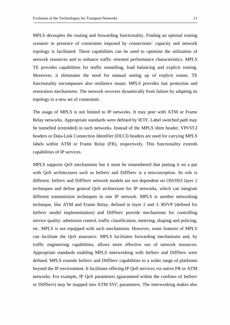
MPLS decouples the routing and forwarding functionality. Finding an optimal routing
scenario in presence of constraints imposed by connections’ capacity and network
topology is facilitated. These capabilities can be used to optimise the utilization of
network resources and to enhance traffic oriented performance characteristics. MPLS
TE provides capabilities for traffic tunnelling, load balancing and explicit routing.
Moreover, it eliminates the need for manual setting up of explicit routes. TE
functionality encompasses also resilience issues. MPLS provides fast protection and
restoration mechanisms. The network recovers dynamically from failure by adapting its
topology to a new set of constraints.
The usage of MPLS is not limited to IP networks. It may peer with ATM or Frame
Relay networks. Appropriate standards were defined by IETF. Label switched path may
be tunnelled (extended) in such networks. Instead of the MPLS shim header, VPI/VCI
headers or Data-Link Connection Identifier (DLCI) headers are used for carrying MPLS
labels within ATM or Frame Relay (FR), respectively. This functionality extends
capabilities of IP services.
MPLS supports QoS mechanisms but it must be remembered that putting it on a par
with QoS architectures such as IntServ and DiffServ is a misconception. Its role is
different. IntServ and DiffServ network models are not dependent on OSI/ISO layer 2
techniques and define general QoS architecture for IP networks, which can integrate
different transmission techniques in one IP network. MPLS is another networking
technique, like ATM and Frame Relay, defined in layer 2 and 3. RSVP (defined for
IntServ model implementation) and DiffServ provide mechanisms for controlling
service quality: admission control, traffic classification, metering, shaping and policing,
etc. MPLS is not equipped with such mechanisms. However, some features of MPLS
can facilitate the QoS assurance. MPLS facilitates forwarding mechanisms and, by
traffic engineering capabilities, allows more effective use of network resources.
Appropriate standards enabling MPLS interworking with IntServ and DiffServ were
defined. MPLS extends IntServ and DiffServ capabilities to a wider range of platforms
beyond the IP environment. It facilitates offering IP QoS services via native FR or ATM
networks. For example, IP QoS parameters (guaranteed within the confines of IntServ
or DiffServ) may be mapped into ATM SVC parameters. The interworking makes also

12 Chapter 2
possible IP leased line service with various parameter guarantees. It is also possible to
establish explicit routes or tunnels with QoS guarantees. Various service classes may be
offered within IP/MPLS networks.
MPLS provides a capability for building reliable Virtual Private Networks (VPNs).
MPLS VPNs are connectionless that is, they do not need a predefined logical or virtual
channel provisioned between two endpoints to establish a connection between the two
endpoints. Various users’ traffic is treated separately within the MPLS network without
the need for encryption or tunneling at lower layers. This eliminates significant
complexity of the connection provisioning process. MPLS VPNs are scalable (as
opposed to connection oriented Frame Relay or ATM VPNs requiring hundreds of
virtual channels for each closed group of customers). Tens of thousands of VPNs may
coexist in the same network. Additionally, MPLS VPNs provide a high level of security
without encryption or layer 2 tunneling. There is no possibility that traffic from one
VPN enters another VPN even though several VPNs coexist within the same network.
Moreover, MPLS provides a capability for consolidation of data, voice and video
services. Each VPN may use its own independent addressing plan. Customers of IP
VPNs usually require some guarantees of service quality. MPLS together with IntServ
or DiffServ provides the ability to meet requirements on multiple service class support,
performance predictability, traffic policing as well as Service Layer Agreement (SLA)
compliance provision and control in an end-to-end relation. Multicast support is another
feature important from the VPN’s perspective.
2.2.1.1. MPLS Resilience
To deliver reliable service, MPLS provides a set of procedures to provide protection of
the traffic carried on different paths. This requires that the label switching routers
(LSRs) support fault detection, fault notification, and fault recovery mechanisms, and
that MPLS signalling supports the configuration of recovery. MPLS specifies a
recovery framework, which is shortly presented in the following.
There are two basic models for path recovery: rerouting and protection switching.
Protection switching and rerouting may be used together.
Evolution of the Technologies for Transport Networks 13
Rerouting. Recovery by rerouting is defined as establishing new paths or path segments
on demand for restoring traffic after the occurrence of a fault. The new paths may be
based upon fault information, network routing policies, pre-defined configurations and
network topology information. Thus, upon detecting a fault, paths or path segments to
bypass the fault are established using signalling. Reroute recovery employs paths
established-on-demand with resources reserved-on-demand.
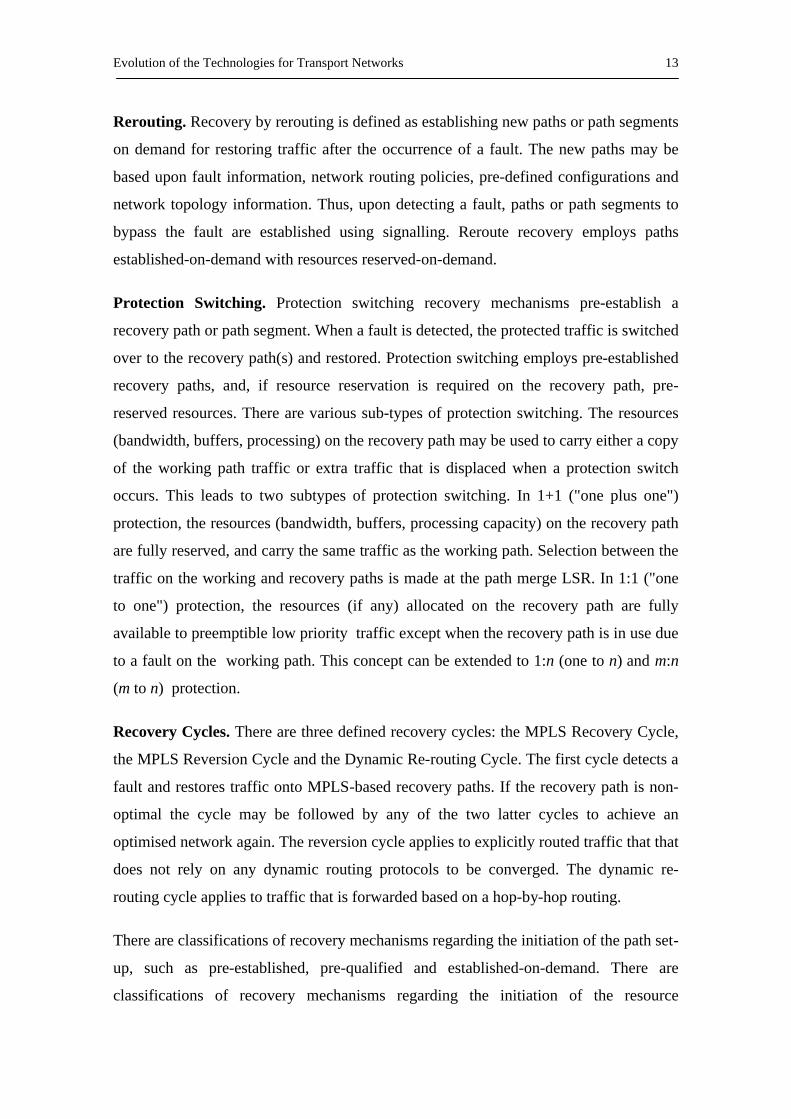
Protection Switching. Protection switching recovery mechanisms pre-establish a
recovery path or path segment. When a fault is detected, the protected traffic is switched
over to the recovery path(s) and restored. Protection switching employs pre-established
recovery paths, and, if resource reservation is required on the recovery path, pre-
reserved resources. There are various sub-types of protection switching. The resources
(bandwidth, buffers, processing) on the recovery path may be used to carry either a copy
of the working path traffic or extra traffic that is displaced when a protection switch
occurs. This leads to two subtypes of protection switching. In 1+1 ("one plus one")
protection, the resources (bandwidth, buffers, processing capacity) on the recovery path
are fully reserved, and carry the same traffic as the working path. Selection between the
traffic on the working and recovery paths is made at the path merge LSR. In 1:1 ("one
to one") protection, the resources (if any) allocated on the recovery path are fully
available to preemptible low priority traffic except when the recovery path is in use due
to a fault on the working path. This concept can be extended to 1:n (one to n) and m:n
(m to n) protection.
Recovery Cycles. There are three defined recovery cycles: the MPLS Recovery Cycle,
the MPLS Reversion Cycle and the Dynamic Re-routing Cycle. The first cycle detects a
fault and restores traffic onto MPLS-based recovery paths. If the recovery path is non-
optimal the cycle may be followed by any of the two latter cycles to achieve an
optimised network again. The reversion cycle applies to explicitly routed traffic that that
does not rely on any dynamic routing protocols to be converged. The dynamic re-
routing cycle applies to traffic that is forwarded based on a hop-by-hop routing.
There are classifications of recovery mechanisms regarding the initiation of the path set-
up, such as pre-established, pre-qualified and established-on-demand. There are
classifications of recovery mechanisms regarding the initiation of the resource

14 Chapter 2
allocation, such as pre-reserved and reserved-on-demand. Finally, recovery strategies
may be classified regarding their scope of the recovery, such as local vs. global repair,
the path mappings, bypass tunnels, fault detection, fault notification and the switch-over
operation. Detailed information may be found in [30].
2.2.2. ATM Layer
Asynchronous Transfer Mode (ATM) is characterized by relaying data packets with a
fix length (53 bytes) called cells, which allow a better treatment of the traffic in
situations of network congestion and make easier the design of switching equipments.
ATM eliminates error control on the transmission and achieves speeds in the order of
155 and 622 Mbps. ATM offers a connection-oriented service with data transferred over
a virtual Circuit (VC). A set of VCs composes a virtual path (VP). Therefore, data from
different connections is distinguished by means of a virtual path identifier (VPI) and a
virtual circuit identifier (VCI) and cells belonging to the same VP are routed. Moreover,
ATM switches may treat the cell stream in different VC connections unequally over the
same channel in order to provide different qualities of services (QoS). The ATM Forum
has defined five ATM services classes, according to the different types of traffic. These
services are: Constant Bit Rate (CBR) is characterized by a continuous stream of bits at
a steady rate, such as TDM traffic; Variable Bit Rate-Real Time (VBR-RT) can be
characterized by voice or video applications that use compression, such as interactive
videoconference; Variable Bit Rate-Non Real Time (VBR-NRT) is used to send traffic
that has a bursty nature in which delay is not so critical, such as video e-mail messages
and file transfers; Available Bit Rate (ABR) traffic can be characterized as busrty traffic
and data that is more tolerant of delays and cell loss; Unspecified Bit Rate (UBR) is a
best-effort that does not specify bit rate or traffic parameters and has no QoS
guarantees.
The ATM reference Model Planes. There are three ATM reference model planes,
which are responsible for signaling, routing, user data transfer and management:
- Control plane. This plane is responsible for generating and managing signaling
requests. The control plane supports call control and connection control

Evolution of the Technologies for Transport Networks 15
functions. Moreover, it supports routing functions such as distribution of
topology and available resource information, and path computation.
- User plane. The user plane is responsible for managing the transfer of data. The
use plane provides for user-to-user information transfer, plus controls that are
required for that information transfer, such as flow control and error recovery.
- Management plane. This plane contains two components: layer management and
plane management. The first manages layer-specifics functions, such as the
detection of failures and protocol problems. The second manages and
coordinates functions related to the complete system.
2.2.3. SDH Layer
Synchronous Digital Hierarchy (SDH) is currently a well-known, mature and
standardized technique [31]. Since it was initially optimized for the transport of 64-
kbps-based TDM services, a rigid capacity of payload as well as coarse fixed-rate
multiplexing hierarchy were defined. These legacy features of SDH cause well-known
problems while transporting data signals that are inherently bursty (especially with
efficient bandwidth utilization). Since data traffic surpassed voice traffic in core
networks these problems become more and more significant and impose new
requirements on transport networks, especially as SDH systems are commonly used as a
basis for many transport networks in the world. The SDH technique still evolves to meet
these requirements. Virtual Concatenation (VC) and Link Capacity Adjustment Scheme
(LCAS) are the most recent concepts.
Virtual Concatenation [31] allows elastic concatenation of several SDH payloads. It
provides effective use of SDH capacity. Virtually concatenated payloads constitute a
Virtual Concatenation Group (VCG). Members of VCG, as opposed to contiguous
concatenation, may not reside in the same STM-N contiguously. They may even reside
at different STM-N interfaces. They are treated within the network separately and
independently. It follows that, they may reach the destination through various routes.
Intermediate nodes do not need to handle virtual concatenation. VC functionality must
be implemented only at path termination nodes. This feature makes deployment of
16 Chapter 2
Virtual Concatenation on legacy SDH equipment of existing networks possible. On the
other hand, it should be remembered that differences in delay of the individual
concatenated signal may occur due to pointer processing at intermediate nodes.
Compensation of differential delays is handled at the destination node. Another
advantage of virtual concatenation is its possibility to divide STM-N bandwidth into
several subrates. Each of the subrates may be used for accommodation of different
service. The bandwidth of STM-N may be shared, for example, by both telephone
service and data signals.
An often-mentioned example [32] of a practical use of virtual concatenation is Gigabit
Ethernet (GbE). VC-4-16c (STM-16) is required to accommodate GbE signals at full
speed under conventional SDH. However, the capacity of 1.4 Gbps is then wasted. On
the other hand, contiguous concatenation of four VC-4 containers (VC-4-4c) provides
too little capacity to fully accommodate GbE signals. The best solution would be
concatenation of seven VC-4 payloads. This is possible with virtual concatenation.
Bandwidth of 1,05 Gbps provided by VC-4-7v VCG is suitable for GbE signals.
Link Capacity Adjustment Scheme (LCAS) is an extension to virtual concatenation. It
makes dynamic alternation of bandwidth of SONET/SDH/OTN transport pipes
possible. This is a key functionality for the transport of data-traffic coming from IP-
applications while saving bandwidth. The number of concatenated payloads may be
increased or decreased at any time without affecting traffic currently being sent.
Moreover, LCAS will automatically decrease the capacity if a member of VCG
experiences a failure in the network, and increase the capacity when the network
recovers. When one of the constituent channels experience failure, the failed channel
will be automatically removed while the remaining channels will still work. Thus, the
available bandwidth will be lowered but the connection will be maintained. It can be
noted that such a solution provides lower probability of a complete connection failure in
such a system.
Synchronization between endpoints during addition or deletion of channels to a VCG is
done via signalling. The entire process takes place via the H4 byte for higher order VC
and K4 byte in lower order VC.

Evolution of the Technologies for Transport Networks 17
Another aspect related to the SDH evolution is deployment of STM-64 and STM-256
interfaces [33]. Equipment supporting both types of interfaces is currently available;
however the latter seams not to become commonly used in the future. It is mainly due to
very high capacity of STM-256 connections that do not have many applications and is
inconvenient to operate. Moreover, STM-256 imposes very strict requirements on the
optical channel quality.
2.2.4. Gigabit Ethernet
Ethernet technology is well known and stable; its applicability to local computer
networks cannot be questioned. Since years, 10 and 100 Mbps Ethernets have been used
for building cost effective, high speed data networks. Last years Gigabit Ethernet
widely came into the metropolitan, regional and even wide area networks. This
technology definitely cannot be omitted in considerations on transport network
evolution scenarios.
Gigabit Ethernet specification, commonly referred to before as an 802.3z standard, is
currently included in the ANSI/IEEE standard 802.3-2002 published in March 2002.
This specification has been approved by ISO/IEC, as well.
Gigabit Ethernet can be used in both half duplex and full duplex mode. In half duplex
mode the frame transmission times were reduced, and then resulting network topology
is affected. The possible topologies for full duplex Gigabit Ethernet are comparable to
the full duplex 100BaseT Ethernet. Gigabit Ethernet used in the full duplex mode
provides simply an encapsulation and framing method for higher layers packets. The
sharing media protocol CSMA-CD cannot be used in this configuration.
The Gigabit Ethernet (GbE) standard defines GMII (Gigabit Media Independent
Interface) to provide interconnect between the MAC sublayer and PHY layer. The use
of GMII supports definition of the range of PHY specifications. For Gigabit Ethernet
the family of 1000Base-X interfaces is available. 1000Base-SX (Short Wavelength
Laser, 860nm), 1000Base-LX (Long Wavelength Laser, 1310nm), as well as
1000Base-T (four pairs of category 5 cable) interfaces provide flexibility in planning
cost effective data networks.
18 Chapter 2
The Gigabit Ethernet technology has been designed to be deployed not only in the
homogenous networks. It is possible to plan, implement and operate 10/100/1000 Mbps
mixed networks. The device referred to as a Multiport Bridge can handle incoming
Ethernet links of various data rates.
Gigabit Ethernet networks are at the moment widely adopted in local and metro area
networks.
10 Gigabit Ethernet continue the evolution towards higher bit rates and extended range.
The 802.3ae working group formed in 1999 decided to adopt for 10 GbE full duplex
operation mode only – there is no need nor possibility to use CSMA/CD protocol for
sharing media access. The important difference is also that only fibre links are defined
for the fastest Ethernet option.
Two types of PHY interfaces are defined, the first one is suitable for local and metro
area networks operations (LAN PHY: 10GBase-X, 10GBase-R), the next one for wide
area networks (WAN PHY:10GBase-W). The 10 Gigabit Ethernet standard proposes
physical interfaces based both on single- and multi-mode fibres. By the use of single
mode fibres, 10 GbE LAN PHY offers higher, compared to 1GbE, data rate and
extended reach. 10 GbE can operate over 40 km long single-mode fibre link.
WAN PHY differs from the LAN PHY implementations by the use of the SDH framing
with reduced functionality. The framing for WAN interfaces takes place at the WAN
Interface Sublayer (WIS). The output from the WAN PHY is compatible with
synchronous frame format (STS-192c or VC-4-64c) and can be easily transported over
OTN. The output from the LAN PHY of 10 Gigabit Ethernet has to be adopted before
entering the OTN; this hopefully can be done with the use of GFP.
Public demonstrations of the 10 Gigabit Ethernet interoperability test took place in the
first half of the year 2002. 10 Gigabit Ethernet networks set up for SuperComm
demonstration comprised of the equipment coming from 15 vendors, about 20 network
nodes were interconnected with more than 200 km of fibres, four different types of PHY
interfaces were adopted in the network. 802.3ae specification of 10 Gigabit Ethernet has

Evolution of the Technologies for Transport Networks 19
been approved by IEEE Standard Board as an official IEEE standard in June 2002, after
about three years of working group activity.
Ethernet technology was also proposed as a base for new, high speed access networks.
Ethernet in the First Mile working group, 802.3ah started its work in the last year. The
scope of the work is adaptation of the Ethernet technology to point-to-point and point-
to-multipoint (E-PON) access networks. A successful standardisation process will
extend the Ethernet coverage, the end-to-end services would be offered to both business
and residential customers.
Future improvement of the quality of services offered in the Ethernet networks can be
achieved through the use of 802.1p (Class of Services) and 802.1q (Virtual LAN)
specifications.
2.2.4.1. Gigabit Ethernet Resilience
Unlike SDH, Ethernet technology does not provide a fast protection mechanism.
Ethernet generally relies on the spanning tree protocol to eliminate all loops from a
switched network. Even though spanning tree protocol can be utilized to achieve path
redundancy, it recovers comparatively slowly from a fiber cut as the recovery
mechanism requires the failure condition to be propagated serially to each upstream
node. Link aggregation (802.1ad) can provide a link level resiliency solution, but it is
comparatively slow (~500ms vs. ~50ms provided by SDH) and not appropriate for
providing path level protection.

ATM PNNI Protocols 21
3. ATM PNNI Protocols
3.1. Introduction
Private Network to Network Interface (PNNI) is a hierarchical link state routing
protocol and a signaling protocol, used together to establish Switched Virtual Circuits
(SVCs) in a private ATM network; in this context, a ``private'' network is one which
uses Network Service Access Point (NSAP) format ATM addresses. The ATM Forum's
main goals in developing PNNI are: Quality of Service support and Universal
scalability.
PNNI signalling is an extension of UNI signalling protocols, making use of well-known
VPI/VCIs to carry signalling messages. PNNI is a map-based routing protocol; that is,
one which distributes descriptive information about the network or portions of the
network, as opposed to distributing routing tables. PNNI mappings abstract sections of
the network, which lie at differing levels of hierarchy; these hierarchical maps allow
sources to select their own routes across the network. Herein lies the biggest departure
from current Internet practice; paths are explicitly chosen by sources rather than fully
distributed, hop-by-hop paths in which each switch or router selects its own next hop.
3.2. PNNI Routing
The PNNI routing protocol is defined [1] to perform both topology/resource state
dissemination and path selection. A hierarchical structure allows PNNI to scale to very
22 Chapter 3
large networks. PNNI routing hierarchy was established in order to reduce the overhead
produced in networks with only a single hierarchical level. Moreover, the routing
hierarchy is automatically configurable in networks in which the address structure
reflects the topology. A brief description of the main protocol features follows.
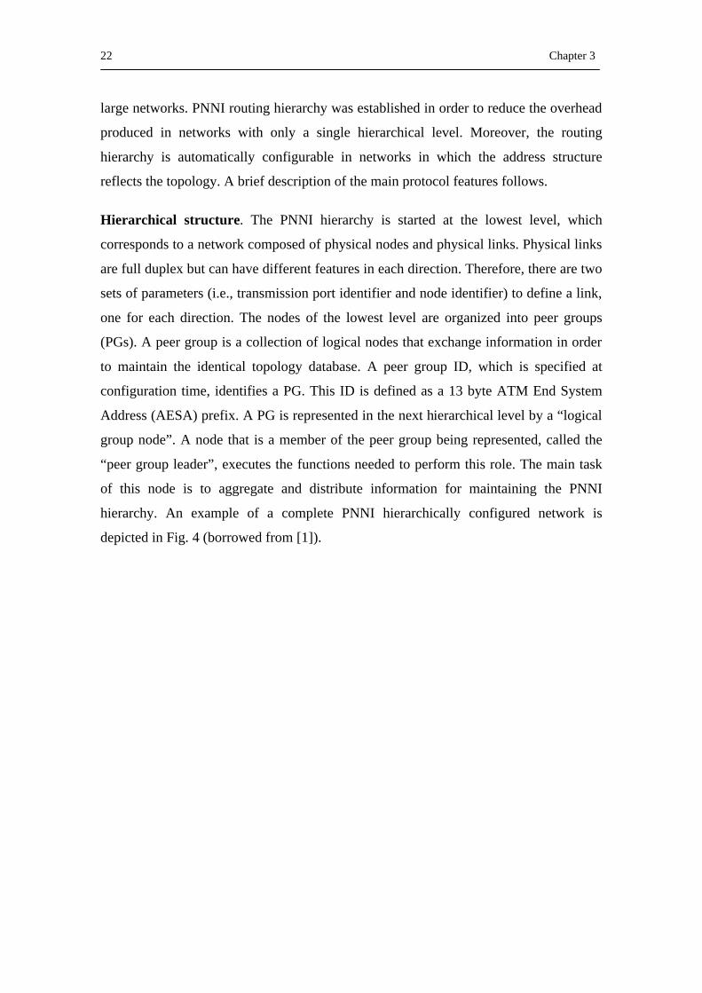
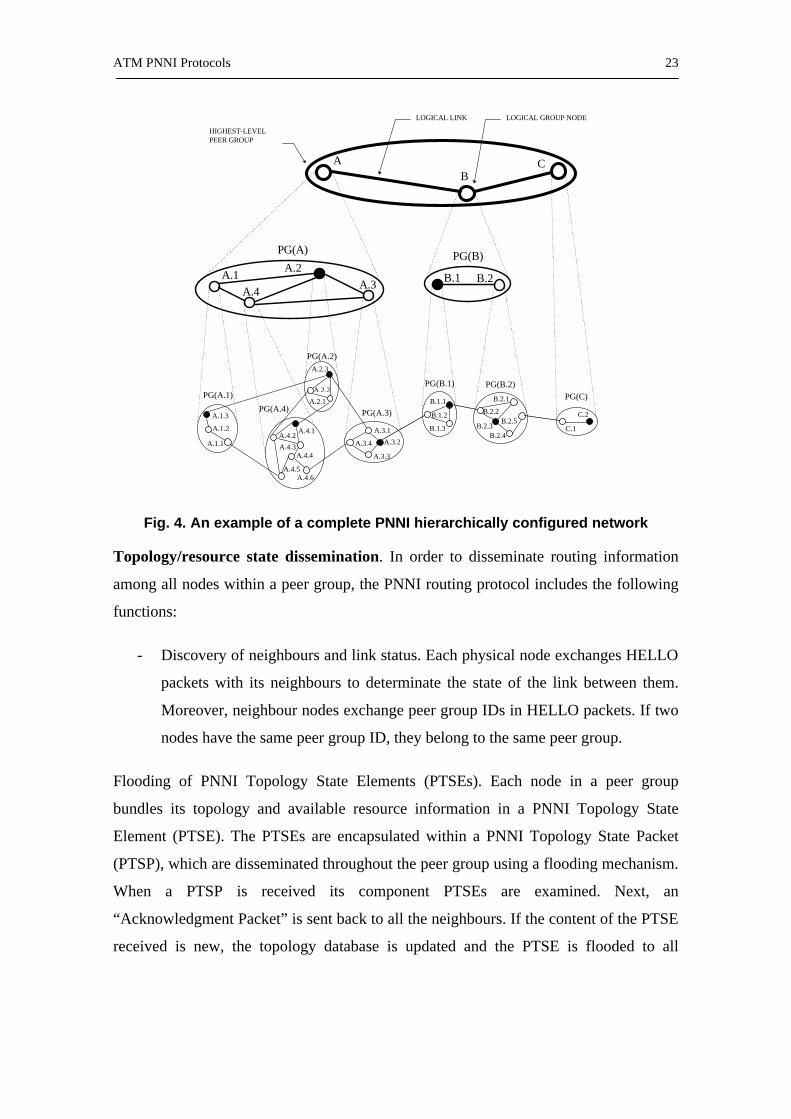
Hierarchical structure. The PNNI hierarchy is started at the lowest level, which
corresponds to a network composed of physical nodes and physical links. Physical links
are full duplex but can have different features in each direction. Therefore, there are two
sets of parameters (i.e., transmission port identifier and node identifier) to define a link,
one for each direction. The nodes of the lowest level are organized into peer groups
(PGs). A peer group is a collection of logical nodes that exchange information in order
to maintain the identical topology database. A peer group ID, which is specified at
configuration time, identifies a PG. This ID is defined as a 13 byte ATM End System
Address (AESA) prefix. A PG is represented in the next hierarchical level by a “logical
group node”. A node that is a member of the peer group being represented, called the
“peer group leader”, executes the functions needed to perform this role. The main task
of this node is to aggregate and distribute information for maintaining the PNNI
hierarchy. An example of a complete PNNI hierarchically configured network is
depicted in Fig. 4 (borrowed from [1]).
ATM PNNI Protocols 23
PG(A.2)
PG(A.4) PG(A.3)
PG(A.1)PG(B.1) PG(B.2)
PG(C)
A.2A.3
A.1
PG(A)
BA C
A.3.1
A.3.4 A.3.2
A.3.3
A.2.2
A.2.3
A.2.1
A.1.3
A.1.2
A.1.1
B.1.2
B.1.1
B.1.3
B.2.2B.2.5
B.2.1
B.2.3B.2.4
C.1
C.2
A.4.4
A.4.5A.4.6
A.4.1A.4.2
A.4.3
A.4B.1 B.2
PG(B)
LOGICAL LINK
HIGHEST-LEVELPEER GROUP
LOGICAL GROUP NODE
Fig. 4. An example of a complete PNNI hierarchically configured network
Topology/resource state dissemination. In order to disseminate routing information
among all nodes within a peer group, the PNNI routing protocol includes the following
functions:
- Discovery of neighbours and link status. Each physical node exchanges HELLO
packets with its neighbours to determinate the state of the link between them.
Moreover, neighbour nodes exchange peer group IDs in HELLO packets. If two
nodes have the same peer group ID, they belong to the same peer group.
Flooding of PNNI Topology State Elements (PTSEs). Each node in a peer group
bundles its topology and available resource information in a PNNI Topology State
Element (PTSE). The PTSEs are encapsulated within a PNNI Topology State Packet
(PTSP), which are disseminated throughout the peer group using a flooding mechanism.
When a PTSP is received its component PTSEs are examined. Next, an
“Acknowledgment Packet” is sent back to all the neighbours. If the content of the PTSE
received is new, the topology database is updated and the PTSE is flooded to all
24 Chapter 3
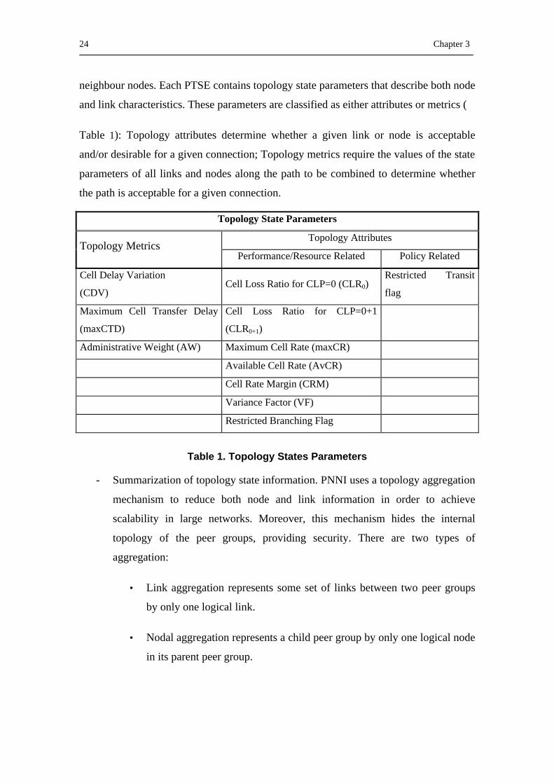
neighbour nodes. Each PTSE contains topology state parameters that describe both node
and link characteristics. These parameters are classified as either attributes or metrics (
Table 1): Topology attributes determine whether a given link or node is acceptable
and/or desirable for a given connection; Topology metrics require the values of the state
parameters of all links and nodes along the path to be combined to determine whether
the path is acceptable for a given connection.
Topology State Parameters
Topology Attributes Topology Metrics
Performance/Resource Related Policy Related
Cell Delay Variation
(CDV) Cell Loss Ratio for CLP=0 (CLR0)
Restricted Transit
flag
Maximum Cell Transfer Delay
(maxCTD)
Cell Loss Ratio for CLP=0+1
(CLR0+1)
Administrative Weight (AW) Maximum Cell Rate (maxCR)
Available Cell Rate (AvCR)
Cell Rate Margin (CRM)
Variance Factor (VF)
Restricted Branching Flag
Table 1. Topology States Parameters
- Summarization of topology state information. PNNI uses a topology aggregation
mechanism to reduce both node and link information in order to achieve
scalability in large networks. Moreover, this mechanism hides the internal
topology of the peer groups, providing security. There are two types of
aggregation:
• Link aggregation represents some set of links between two peer groups
by only one logical link.
• Nodal aggregation represents a child peer group by only one logical node
in its parent peer group.
ATM PNNI Protocols 25
In addition, PNNI performs an address summarization to reduce the amount of
address information that has to be distributed in the PNNI network. This
summary consists of using a “reachable address prefix” in order to represent a
collection of end systems and/or node addresses, which start with the given
prefix. The reachable address prefixes can be either summary addresses or
exterior addresses.
Path selection. ATM is a connection-oriented technology. This means that the selected
path for the virtual connection or virtual path establishment must be in use for an
extended period. Therefore, an inefficient routing decision will affect a connection as
long as it is open. PNNI does not specify a routing algorithm to compute the path but it
must comply with the PNNI specifications. The path calculation is based on the network
topology database at the source node, which is obtained from topology information
advertisement, generated by all other nodes. In this path calculation, the QoS of the path
is calculated by accumulating its additive parameters (CLR, CTD and CDV) and by
calculating the minimum of the advertised AvCR for each link in the route. If the total
QoS of the path meets the QoS requirements of the call and the path has enough
bandwidth to carry the call, then the path is considered acceptable for a Generic Call
Admission Control (GCAC). If the advertised performance of the path is satisfactory,
the source node initializes the call setup process. Otherwise, the next algorithm from the
path calculation sequence is used or the call is blocked.
In an actual network, no node can know the actual state of the network in real time
because of inherent latencies in distributing the advertised QoS parameters. Moreover,
aggregation methods intend to reduce the topology representation expense for large
networks through the process of summarizing the network topology. Both, updating and
aggregation processes introduce inaccuracy on routing information and, consequently,
an increase of blocked calls. Therefore, routing algorithm must be a hierarchical QoS
routing algorithm with the ability of reduces the routing inaccuracy effects.
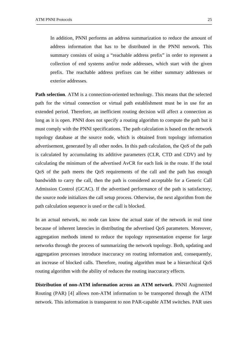
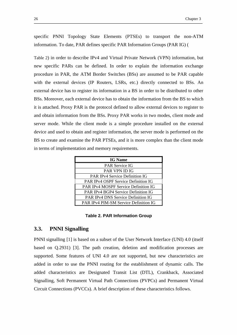
Distribution of non-ATM information across an ATM network. PNNI Augmented
Routing (PAR) [4] allows non-ATM information to be transported through the ATM
network. This information is transparent to non PAR-capable ATM switches. PAR uses
26 Chapter 3
specific PNNI Topology State Elements (PTSEs) to transport the non-ATM
information. To date, PAR defines specific PAR Information Groups (PAR IG) (
Table 2) in order to describe IPv4 and Virtual Private Network (VPN) information, but
new specific PARs can be defined. In order to explain the information exchange
procedure in PAR, the ATM Border Switches (BSs) are assumed to be PAR capable
with the external devices (IP Routers, LSRs, etc.) directly connected to BSs. An
external device has to register its information in a BS in order to be distributed to other
BSs. Moreover, each external device has to obtain the information from the BS to which
it is attached. Proxy PAR is the protocol defined to allow external devices to register to
and obtain information from the BSs. Proxy PAR works in two modes, client mode and
server mode. While the client mode is a simple procedure installed on the external
device and used to obtain and register information, the server mode is performed on the
BS to create and examine the PAR PTSEs, and it is more complex than the client mode
in terms of implementation and memory requirements.
IG Name PAR Service IG PAR VPN ID IG
PAR IPv4 Service Definition IG PAR IPv4 OSPF Service Definition IG
PAR IPv4 MOSPF Service Definition IG PAR IPv4 BGP4 Service Definition IG PAR IPv4 DNS Service Definition IG
PAR IPv4 PIM-SM Service Definition IG
Table 2. PAR Information Group
3.3. PNNI Signalling
PNNI signalling [1] is based on a subset of the User Network Interface (UNI) 4.0 (itself
based on Q.2931) [3]. The path creation, deletion and modification processes are
supported. Some features of UNI 4.0 are not supported, but new characteristics are
added in order to use the PNNI routing for the establishment of dynamic calls. The
added characteristics are Designated Transit List (DTL), Crankback, Associated
Signalling, Soft Permanent Virtual Path Connections (PVPCs) and Permanent Virtual
Circuit Connections (PVCCs). A brief description of these characteristics follows.

ATM PNNI Protocols 27
Designated Transit List (DTL): When a connection request arrives at an ATM switch
through the UNI, this switch then computes a path through the ATM network,
depending on its knowledge of the network topology and the connection requirements.
This process is called "Generic Connection Admission Control (GCAC)". It then sends
a set-up message to the next hop, which contains the computed path in the form of a
path vector. Thus, PNNI uses a kind of "source routing". In ATM terminology, the path
vector is called the "Designated Transit List (DTL)". It should be noted, however, that
each DTL only contains entries for nodes belonging to one hierarchical level. Hence, if
the network consists of more than one level, then more than one DTL will be
transmitted with the set-up message (one for each level) forming a so-called
"hierarchically complete" source route. The DTL corresponding to the lowest level
contains only the switches that are part of the ingress switch's PG (i.e., the ones that the
ingress switch knows about). The rest of the path (outside the PG) is only described in
higher level DTLs that contain higher level Logical Group Nodes (LGN). Thus, this
route is called a "partial source route". All DTLs include the current node in their list, as
well.
When the set-up message enters a different PG, the entry switch (which is not
necessarily a Peer Group Leader) uses its knowledge of this PG's topology and alters the
lowest level DTL to use the switches belonging to this PG. Thus, the entry switches of
the lowest level PGs define the full lowest level path.
Crankbank: Along the path of the set-up message, the necessary resources are
allocated at each node. This process is called "Actual Call Admission Control
(ACAC)". However, there is the possibility that there are no suitable resources in the
calculated route due to inaccurate topology and resource information residing in the
node that calculated it. A "crankback" mechanism deals with this situation. This
mechanism works as follows: when a switch on the chosen route (DTL) cannot deliver
the required resources, the entry switch that calculated this part of the route (this DTL)
is asked to calculate a new route. If this switch is not able to, the call is cranked back
even further, to the node that calculated the immediately higher-level DTL, and so on.
To make this recalculation possible, all nodes that calculate new routes must store the
SETUP message and the DTLs that they received from the previous node. The nodes
28 Chapter 3
that are requested to produce alternative DTLs must do so in a way that satisfies two
limitations:
- All higher-level DTLs must be obeyed. This means that a node calculates an
alternative path only for the PG it belongs to.
- The links and/or nodes where the previous connection set-up failed must be
avoided.
Associated Signalling: In PNNI, the virtual channel with Virtual Path Identifier
(VPI)=0 and Virtual Circuit Identifier (VCI) =5 is used to control the remaining virtual
channels and paths on a physical link. This is called non-associated signalling.
However, there is the case of signalling and routing over multiple virtual path
connections (VPCs) to multiple destinations through a single physical interface. In this
case, the Virtual Circuits (VCs) inside this VPC are not controlled by the default
channel mentioned above (VPI=0, VCI=5), but by a virtual channel belonging to the
same VPC (i.e., by the associated signalling channel).
Soft PVPCs and PVCCs. PNNI supports the establishment of Soft Permanent Virtual
Path/Channel Connections (Soft PVPCs/PVCCs). The qualifier “permanent” means that
these VPCs/VCCs are established by network management, rather than on client
demand through UNI signalling. The qualifier “soft” means that the management
system does not communicate with all the intermediate switches that constitute the
chosen path to establish the connection (as opposed to the just “permanent” case).
Instead, it demands a connection from one of the two endpoint switches and the
connection is then established by means of signalling among the switches.
The endpoint switch that the management system communicates with is called the
“calling endpoint”. The calling endpoint is responsible for establishing and releasing the
connection, initiating the signalling to perform these actions.
Signalling Messages. Connection set-up in PNNI relies on a Source Routing
mechanism that provides/specifies the path to the connection destination based on the
source’s current view of the network. This view may be based on a set of DTLs, which

ATM PNNI Protocols 29
are appropriately processed in downstream nodes so as to extract the full path to the
destination.
All the messages have a similar format consisting of four common information
elements: (a) a Protocol discriminator, (b) a Call reference, (c) a message type and (d)
the message length, which is used for parsing the last variable part of the message
according to the message type. The call set-up/release message exchange within the
scope of the PNNI is depicted in Fig. 5:
Calling Network
Called Network
CALL PROC
SETUP
CONNECT
RELEASE COMPLETE
RELEASE
Fig. 5. PNNI signalling message exchange during call set-up and release
There are also signalling messages for point to multipoint call and connection control
[1], which are more characteristic of the separation between call and connection control
in PNNI.
3.4. PNNI Addressing
An ATM address can be either an E.164 number of 15 digits or an ATM End System
Address (AESA) of 20 bytes.
In the first case, E.164 numbering is defined by International Telecommunication
Union-Telecommunication Sector (ITU-T) Recommendation E.164, which specifies the
use of the number in an ISDN/telephony call set-up. ATM Forum specifications
recognise the E.164 International format, such as it is shown in Fig. 6.
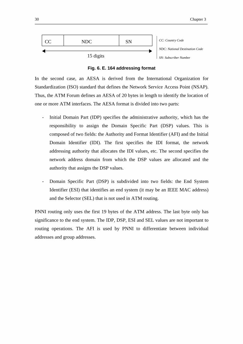
30 Chapter 3
CC NDC SN
15 digits
Fig. 6. E. 164 addressing format
In the second case, an AESA is derived from the International Organization for
Standardization (ISO) standard that defines the Network Service Access Point (NSAP).
Thus, the ATM Forum defines an AESA of 20 bytes in length to identify the location of
one or more ATM interfaces. The AESA format is divided into two parts:
- Initial Domain Part (IDP) specifies the administrative authority, which has the
responsibility to assign the Domain Specific Part (DSP) values. This is
composed of two fields: the Authority and Format Identifier (AFI) and the Initial
Domain Identifier (IDI). The first specifies the IDI format, the network
addressing authority that allocates the IDI values, etc. The second specifies the
network address domain from which the DSP values are allocated and the
authority that assigns the DSP values.
- Domain Specific Part (DSP) is subdivided into two fields: the End System
Identifier (ESI) that identifies an end system (it may be an IEEE MAC address)
and the Selector (SEL) that is not used in ATM routing.
PNNI routing only uses the first 19 bytes of the ATM address. The last byte only has
significance to the end system. The IDP, DSP, ESI and SEL values are not important to
routing operations. The AFI is used by PNNI to differentiate between individual
addresses and group addresses.
CC: Country Code
NDC: National Destination Code
SN: Subscriber Number

31
PART II
INTERCONNECTION OF IP/MPLS-ATM NETWORKS
USING PNNI
The association between IP/MPLS and ATM has been a topic that has provided several
standards because of the fact that both technologies are widely deployed and each has
its potency. This part deals with a PNNI routing protocol based solution that provides
integration between IP/MPLS and ATM. Moreover, it addresses the problem of
minimizing the end-to-end setup time in an MPLS-ATM-MPLS environment.
Therefore, in Chapter 5 a fast mechanism to set up LSPs in such environment is
proposed. Finally, Chapter 6 is devoted to applying the Traffic Engineering (TE) based
routing algorithms to the proposed fast set-up mechanism to reduce the congestion
effects in the different IP/MPLS domains.

MPLS over ATM: State of the Art and Problem Definition 33
4. MPLS over ATM: State of the Art and Problem Definition
In this Chapter existing solutions (mostly specified in Internet Engineering Task Force
(IETF) RFCs ) for establishing LSPs through ATM networks are discussed. Three
different approaches are considered: “distributing MPLS Labels between ATM LSRs”,
“tunnelling through ATM”, and “communicating a Virtual Connection Identifier
(VCID) within ATM signalling messages”. These approaches exhibit a time to set up a
real-time channel higher than the solution proposed by this thesis, as demonstrated in
Chapter 5.
4.1. Integrating MPLS with IP and ATM
ATM has experimented considerable growth in the Wide Area Networks due to offer
QoS and class of service guarantees, which have allowed its general deployment in the
carrier and service providers. QoS has given ATM the multiservices capability to offer
separate classes of services for voice, video and data. This increase of ATM networks in
the Internet, which is based on IP, has caused the proliferation of IP networks overlaid
on an ATM infrastructure.
The association between IP and ATM has been a topic that has provided several
standards because of the fact that both technologies are widely deployed and each has
its potency. Groups such as IETF and ATM Forum have worked to provide solutions
focussed mainly on how the capabilities of ATM and IP can be shared.
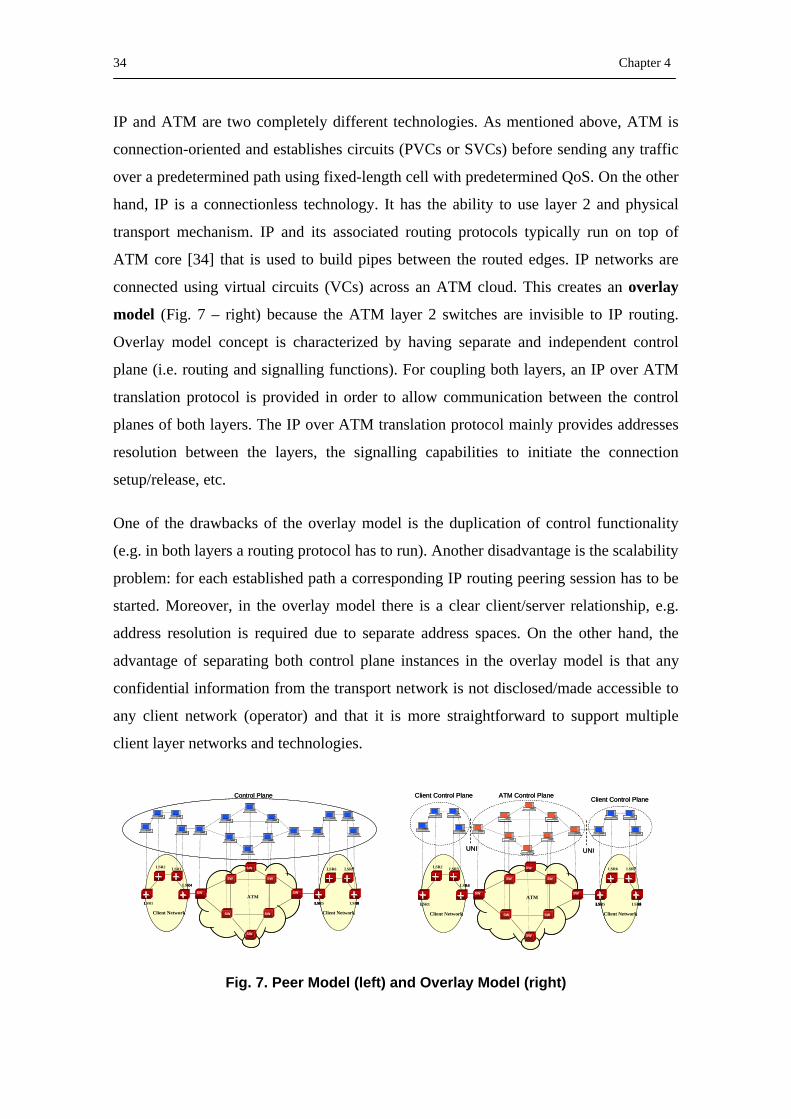
34 Chapter 4
IP and ATM are two completely different technologies. As mentioned above, ATM is
connection-oriented and establishes circuits (PVCs or SVCs) before sending any traffic
over a predetermined path using fixed-length cell with predetermined QoS. On the other
hand, IP is a connectionless technology. It has the ability to use layer 2 and physical
transport mechanism. IP and its associated routing protocols typically run on top of
ATM core [34] that is used to build pipes between the routed edges. IP networks are
connected using virtual circuits (VCs) across an ATM cloud. This creates an overlay
model (Fig. 7 – right) because the ATM layer 2 switches are invisible to IP routing.
Overlay model concept is characterized by having separate and independent control
plane (i.e. routing and signalling functions). For coupling both layers, an IP over ATM
translation protocol is provided in order to allow communication between the control
planes of both layers. The IP over ATM translation protocol mainly provides addresses
resolution between the layers, the signalling capabilities to initiate the connection
setup/release, etc.
One of the drawbacks of the overlay model is the duplication of control functionality
(e.g. in both layers a routing protocol has to run). Another disadvantage is the scalability
problem: for each established path a corresponding IP routing peering session has to be
started. Moreover, in the overlay model there is a clear client/server relationship, e.g.
address resolution is required due to separate address spaces. On the other hand, the
advantage of separating both control plane instances in the overlay model is that any
confidential information from the transport network is not disclosed/made accessible to
any client network (operator) and that it is more straightforward to support multiple
client layer networks and technologies.
Fig. 7. Peer Model (left) and Overlay Model (right)
OXC
LSR5
LSR6 LSR7
LSR8
LSR2 LSR3
LSR4
LSR1
SW SW
SW
OXC
SW
OXC
Client Network Client Network
ATM
SW
SW
OXCOXCSWSW
Control Plane
OXC
LSR5
LSR6 LSR7
LSR8LSR5
LSR6 LSR7
LSR8
LSR2 LSR3
LSR4
LSR1
SW SW
SW
OXC
SW
OXC
Client Network Client Network
ATM
SW
SW
OXCOXCSWOXCSWSWSW
Control Plane
OXC
LSR5
LSR6 LSR7
LSR8
LSR2 LSR3
LSR4
LSR1
SW SW
SW
OXC
SW
OXC
Client Network Client Network
ATM
SW
SW
OXCOXCSWSW
ATM Control PlaneClient Control PlaneClient Control Plane
UNI UNI
OXC
LSR5
LSR6 LSR7
LSR8LSR5
LSR6 LSR7
LSR8
LSR2 LSR3
LSR4
LSR1
SW SW
SW
OXC
SW
OXC
Client Network Client Network
ATM
SW
SW
OXCOXCSWOXCSWSWSW
ATM Control PlaneClient Control PlaneClient Control Plane
UNI UNI

MPLS over ATM: State of the Art and Problem Definition 35
MPLS solves the overlay problems by eliminating the notion of an ATM cloud [35].
With MPLS, ATM switches are made IP-capable, and the ATM links are treated as IP
links. In this way, each ATM switch can become an IP routing peer. This is known as a
peer model concept (Fig. 7 - left) in which a single control plane controls both IP and
ATM layers. The peer model has some important advantages. First of all, duplication of
functionality is avoided. Secondly, the disadvantages of client/server relationship
between IP and ATM do not exist any more. On the other hand, the peer model is not
applicable to all imaginable business models. For example, an Internet Service Provider
(ISP) and a Transport Network operator may not allow that the control over their
network is taken over by the other one. The peer model is also limited to a single
domain or Autonomous System, and thus there is no way to reduce the route
computation time by dividing the network into sub-domains.
Fig. 8. Augmented Model
A hybrid option between peer and overlay model is the augmented model (Fig. 8). The
augmented model is quite similar to the overlay model, in the sense that both layers may
have their own control plane instance. However, some control information as
reachability information, available resources, etc. may be revealed through the interface
between both layers. In other words, the client layer reachability and available resource
information is carried through the ATM network, but ATM addresses are not propagate
to the client
OXC
LSR5
LSR6 LSR7
LSR8
LSR2 LSR3
LSR4
LSR1
SW SW
SW
OXC
SW
OXC
Client Network Client Network
ATM
SW
SW
OXCOXCSWSW
ATM Control PlaneClient Control PlaneClient Control Plane
UNI UNI
OXC
LSR5
LSR6 LSR7
LSR8LSR5
LSR6 LSR7
LSR8
LSR2 LSR3
LSR4
LSR1
SW SW
SW
OXC
SW
OXC
Client Network Client Network
ATM
SW
SW
OXCOXCSWOXCSWSWSW
ATM Control PlaneClient Control PlaneClient Control Plane
UNI UNI

36 Chapter 4
4.2. Distribution of MPLS Information through an ATM Network
Label Distribution between ATM-LSRs (Peer Model). In [7] a solution for
distributing MPLS labels through an ATM network is presented. This solution considers
that all the network nodes are ATM-Label Switching Routers (ATM-LSRs) (Fig. 9). In
this way, ATM routing and signalling algorithms are not necessary. An ATM-LSR
implements the label switching control and forwarding components specified in [8].
Moreover, it is composed of Label-switch Controlled ATM (LC-ATM) interfaces and is
capable of forwarding cells between them, using the Virtual Circuit Identifier (VCI) or
Virtual Path Identifier (VPI) field to carry MPLS labels.
An ATM-LSR is defined with the restrictions imposed by the ATM specifications.
Therefore, the ATM-LSR behaviour is affected by the characteristics of the ATM
switches. Because the label swapping function is performed in the VCI or VPI fields of
the cell header, the size and placement of the labels are fixed by the cell header format.
Fig. 9. Label Distribution between ATM-LSRs
A different situation is produced when there are non LSR-capable ATM switches in the
ATM network. In this case, the connection between two ATM-LSRs can be set up via
either an ATM PVC (Permanent Virtual Circuit) or an ATM Switched Virtual Circuit
(SVC). When a PVC is set up, MPLS cannot use the VPI field because it is used to
establish the path. The labels will only be able to be transported in the VCI field. This
implies a size restriction on the MPLS label. However, if the path is an SVC then both
BR1
BR3
BR2
BR4
ATMBackbone
VPI/VCI
LABEL
BR1
BR3
BR2
BR4
ATMBackbone
VPI/VCI
LABEL
LSR
ATM Switch
LSR
ATM Switch
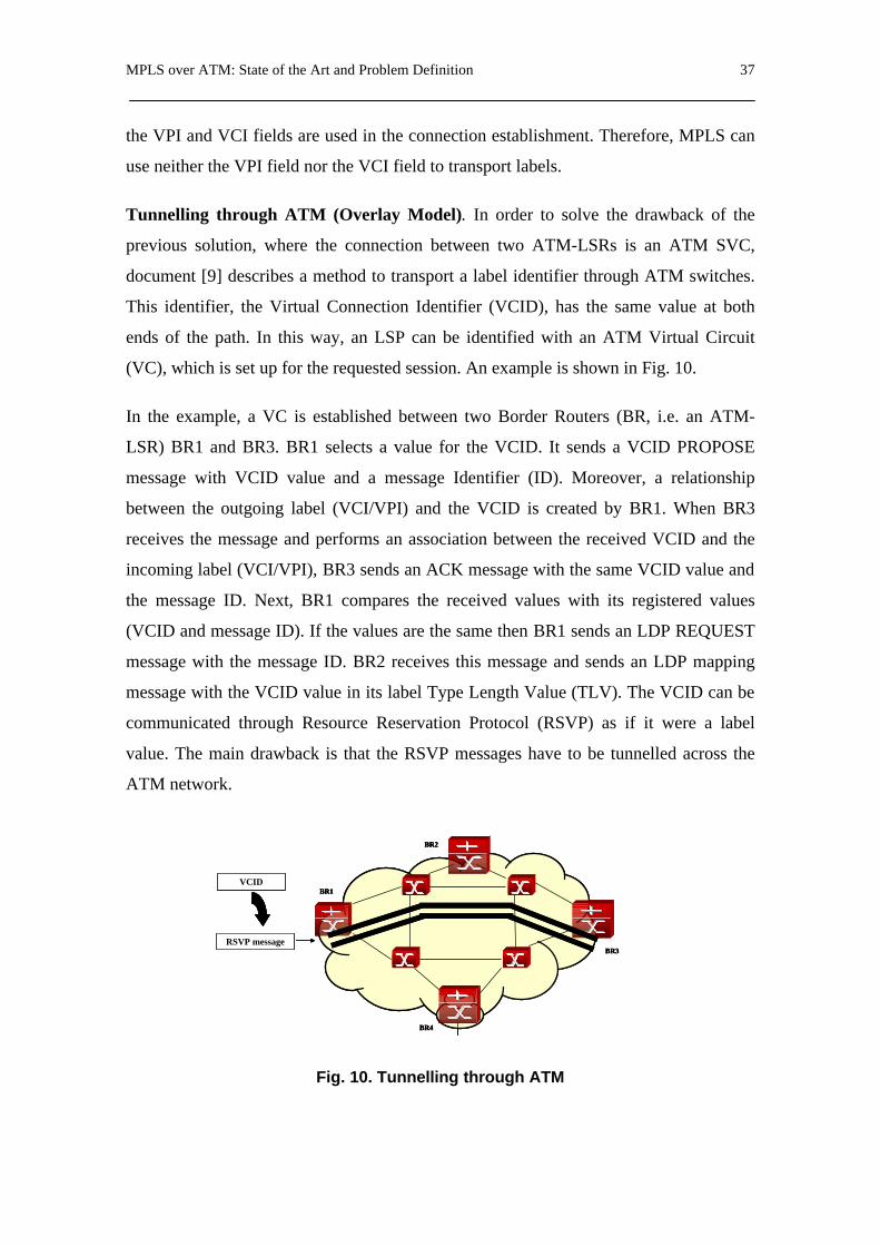
MPLS over ATM: State of the Art and Problem Definition 37
the VPI and VCI fields are used in the connection establishment. Therefore, MPLS can
use neither the VPI field nor the VCI field to transport labels.
Tunnelling through ATM (Overlay Model). In order to solve the drawback of the
previous solution, where the connection between two ATM-LSRs is an ATM SVC,
document [9] describes a method to transport a label identifier through ATM switches.
This identifier, the Virtual Connection Identifier (VCID), has the same value at both
ends of the path. In this way, an LSP can be identified with an ATM Virtual Circuit
(VC), which is set up for the requested session. An example is shown in Fig. 10.
In the example, a VC is established between two Border Routers (BR, i.e. an ATM-
LSR) BR1 and BR3. BR1 selects a value for the VCID. It sends a VCID PROPOSE
message with VCID value and a message Identifier (ID). Moreover, a relationship
between the outgoing label (VCI/VPI) and the VCID is created by BR1. When BR3
receives the message and performs an association between the received VCID and the
incoming label (VCI/VPI), BR3 sends an ACK message with the same VCID value and
the message ID. Next, BR1 compares the received values with its registered values
(VCID and message ID). If the values are the same then BR1 sends an LDP REQUEST
message with the message ID. BR2 receives this message and sends an LDP mapping
message with the VCID value in its label Type Length Value (TLV). The VCID can be
communicated through Resource Reservation Protocol (RSVP) as if it were a label
value. The main drawback is that the RSVP messages have to be tunnelled across the
ATM network.
Fig. 10. Tunnelling through ATM
BR1
BR3
BR2
BR4
RSVP message
VCIDBR1
BR3
BR2
BR4
BR1
BR3
BR2
BR4
RSVP message
VCID
RSVP message
VCID

38 Chapter 4
Communicating the VCID within ATM signalling messages. In order to establish a
VCID end-to-end along a path, another mechanism has been defined in [10]. It consists
of a method to transport the VCID in an ATM signalling message. This method
differentiates two kinds of sessions, Long-live and QoS-sensitive sessions. In the first
type, the call set-up is started when a Long-live session is detected. In the second type,
the call set-up is started by a signalling protocol (e.g. Reservation Protocol, RSVP).
When RSVP requests a connection across the ATM network, an ATM signalling
process is triggered. This procedure is based on B-ISDN signalling where a session
identifier and an element to transport session information are included. This element,
the Generic Identifier Element (GIT), allows user identifiers to be transported end-to-
end in ATM networks. The GIT is an optional information element in both the Q.2931
and Q.2971 UNI signalling protocols. The signalling messages (such as SETUP,
RELEASE, etc.) are transferred between end users through the ATM network. Each
message has to contain 3 Generic Identifier Elements, which are transparent to the ATM
network. The format of a GIT is shown in Fig. 11.
Fig. 11. Communicating the VCID within ATM signalling messages
The existing solutions described above require either having an IP/MPLS Router on top
of the ATM switches, or establishing a tunnel across the ATM backbone. Certainly,
these approaches may provide QoS to the channel but the set-up time is high.
BR1
BR3
BR2
BR4
BR1
BR3
BR2
BR4
Signalling messagesSignalling messages
Information Element Identifier= Generic identifier
transportIE (0x7F)
1
Ext Coding standard IE instruction field 2
Length of contents of information element 3-4
Identifier related standard / application = MPLS (0x06) 5
Identifier type= Resource(0x02) 6
Identifier length=4 octets(0x04) 7
VCID
(4 octets) 11
Generic Identifier Element

MPLS over ATM: State of the Art and Problem Definition 39
4.3. Problem Definition
A routing algorithm running on the ingress node computes the route using the topology
and available resource information of the total network contained on a database, and the
available resources in the ingress node (e.g. available capacity on its links), which
depend on the number of active connections at that moment. If the call set-up time is too
large, it is possible that the routing algorithm computes and selects a route that is being
established at that moment. Since the routing information used to establish the first
route has not been updated in the source node because the set-up process is not finished,
the second path is computed using inaccurate information. Therefore, this path set-up
could be blocked due to some node belonging to the computed path does not fulfil the
QoS requirements.
In this part of the thesis, we address the problem of minimizing the end-to-end setup
time in an MPLS-ATM-MPLS environment. Our approach is to reduce the time
between the transmission of the set-up message from the source node and the receipt of
the connection message. First of all, we discuss the existing mechanism to establish a
path in this environment. Next, we propose a new method to reduce the set-up time,
which is based on the augmented model concept discussed above. Finally, we justify the
need for providing QoS requirements for the fast mechanism used to set up LSPs.


PNNI Adaptation for LSP Set-up in MPLS-ATM Integrated Environments 41
5. PNNI Adaptation for LSP Set-up in MPLS-ATM Integrated Environments
A more appropriate and general solution would integrate the MPLS and ATM
technologies. This chapter deals with a PNNI routing protocol based solution that
provides such integration, and proposes a mechanism to set up LSPs faster than the
existing solutions.
5.1. MPLS-ATM Integration based on PNNI
One of the objectives of this thesis is to transport the information required by the MPLS
protocol between IP/MPLS networks connected through an ATM backbone. Therefore,
PNNI Augmented Routing (PAR) [5][6] is considered to be the appropriate mechanism
to perform this task. PAR defines specific PAR Information Groups (PAR IG) to
describe IPv4 and VPN information. The ATM Border Switches (BSs) are assumed to
be PAR capable, with the external devices (IP Routers, LSRs, etc.) directly connected to
a BS. An external device has to register its information in the BS to be distributed to
other BSs. Moreover, each external device has to obtain the information from the BS to
which it is attached. In order to use the PAR mechanisms to transport MPLS
information, a new PAR IG has to be defined and the architecture of the Border Router
(BR) has to be modified. Taking these facts into consideration, this thesis proposes

42 Chapter 5
defining a PAR MPLS Services Information Group, as shown in Fig. 13. This new PAR
IG allows MPLS labels to be distributed through the ATM backbone [11].
Fig. 12. Border Router Architecture
Fig. 13. PAR MPLS services IG format
Concerning the BR architecture, a Proxy PAR Capable Label Switching Router (PPAR-
LSR) consisting of the following elements is proposed (see Fig. 12):
Forwarding Table
MPLSfunctions+ NetworkLayerRouting
Proxy PAR Capable ATM Switch (Server)
Registration/query
C IG Name Nested in768 PAR Service IG PTSE (64)776 PAR VPN ID IG PAR Service IG (768)784 PAR IPv4 Service Definition IG PAR VPN ID IG (776) / PAR
Service IG (768)792 PAR MPLS Services Definition IG PAR Services IG (768)
800 PAR IPv4 OSPF Service DefinitionIG
PAR IPv4 Service Definition IG(784)
801 PAR IPv4 MOSPF Service DefinitionIG
PAR IPv4 Service Definition IG(784)
802 PAR IPv4 BGP4 Service DefinitionIG
PAR IPv4 Service Definition IG(784)
803 PAR IPv4 DNS Service Definition IG PAR IPv4 Service Definition IG(784)
804 PAR IPv4 PIM-SM ServiceDefinition IG
PAR IPv4 Service Definition IG(784)
Offset Size (bytes) Name Function/Description0 2 Type Type=792 (PAR MPLS Service Definition IG)2 2 Length
4 4 IP address The IP address or IP address prefix Dest.8 4 MPLS Label
12 8 Service Mask Bitmask of registered services.

PNNI Adaptation for LSP Set-up in MPLS-ATM Integrated Environments 43
- An LSR performing both the routing functions of the network layer and the
typical MPLS functions. A Proxy PAR client is added to register and to obtain
information about the Proxy PAR server.
- An ATM switch utilizing the PAR protocol, with the Proxy PAR server
installed.
- A forwarding table to establish a relation between MPLS labels and ATM
outgoing interfaces.
5.2. Fast LSP set-up Mechanism
Once we have a solution for transporting MPLS information from one IP/MPLS
network to another IP/MPLS network through an ATM backbone, the next step is to set
up an end-to-end LSP between two LSRs belonging to the different MPLS networks,
and do it faster than the existing solutions explained in Chapter 4. Consider the scenario
depicted in Fig. 15: the solution proposed above has the advantage of allowing a path to
be set up between an LSR of Network Domain 1 (ND1) and an LSR directly connected
to a BR of ND2 (e.g. LSR9 in Fig. 14). The problem appears when there is more than
one intermediate LSR before the destination LSR, i.e. the destination LSR belongs to an
IP/MPLS network (e.g. LSR8 in ND3). This situation must use a Label Distribution
Protocol (LDP) in ND3 to set up the LSP from BR3 to destination LSR8. Therefore,
considering that RSVP is the LDP used to set up the LSP in both IP/MPLS domains,
this thesis proposes proceeding as follows [12]:
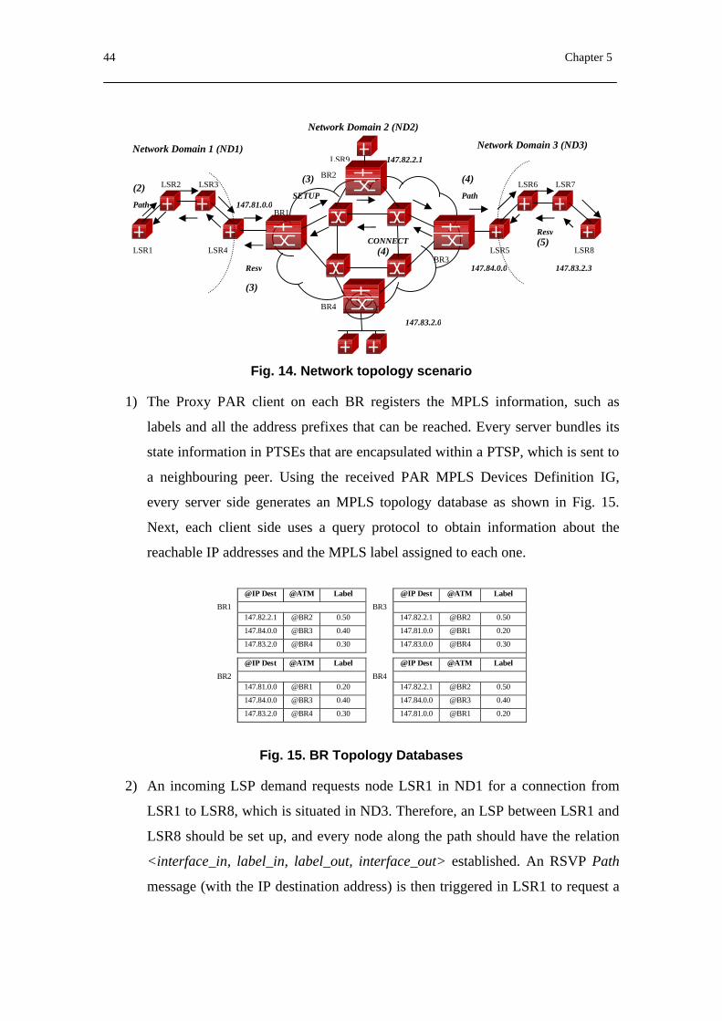
44 Chapter 5
Fig. 14. Network topology scenario
1) The Proxy PAR client on each BR registers the MPLS information, such as
labels and all the address prefixes that can be reached. Every server bundles its
state information in PTSEs that are encapsulated within a PTSP, which is sent to
a neighbouring peer. Using the received PAR MPLS Devices Definition IG,
every server side generates an MPLS topology database as shown in Fig. 15.
Next, each client side uses a query protocol to obtain information about the
reachable IP addresses and the MPLS label assigned to each one.
@IP Dest @ATM Label @IP Dest @ATM Label
BR1 BR3147.82.2.1 @BR2 0.50 147.82.2.1 @BR2 0.50
147.84.0.0 @BR3 0.40 147.81.0.0 @BR1 0.20
147.83.2.0 @BR4 0.30 147.83.0.0 @BR4 0.30
@IP Dest @ATM Label @IP Dest @ATM Label
BR2 BR4147.81.0.0 @BR1 0.20 147.82.2.1 @BR2 0.50
147.84.0.0 @BR3 0.40 147.84.0.0 @BR3 0.40
147.83.2.0 @BR4 0.30 147.81.0.0 @BR1 0.20
Fig. 15. BR Topology Databases
2) An incoming LSP demand requests node LSR1 in ND1 for a connection from
LSR1 to LSR8, which is situated in ND3. Therefore, an LSP between LSR1 and
LSR8 should be set up, and every node along the path should have the relation
<interface_in, label_in, label_out, interface_out> established. An RSVP Path
message (with the IP destination address) is then triggered in LSR1 to request a
LSR1
LSR2 LSR3
LSR4
BR1
BR2
BR4
BR3 LSR5
LSR6 LSR7
LSR8
Resv
Resv
Path Path SETUP
CONNECT
147.83.2.0
147.82.2.1
147.84.0.0
147.81.0.0
(2)
(3)
(3) (4)
(4) (5)
147.83.2.3
Network Domain 3 (ND3)
Network Domain 2 (ND2)
LSR9 Network Domain 1 (ND1)

PNNI Adaptation for LSP Set-up in MPLS-ATM Integrated Environments 45
label. At the moment this message reaches BR1 it receives the label 0.40, which
is bound to the indicated destination address.
3) BR1 returns a Resv message to LSR1. Simultaneously, BR1 triggers the VC
establishment mechanism to the BR3 ATM address given by the table in Fig. 15.
A SETUP message is used to set up the connection, and could contain some
Generic Identifier Information Elements that will be transported through the
ATM network as opaque information unless they contain any coding rule errors.
At this point, this thesis proposes adding a new Generic Identifier Information
Element in the SETUP message with an Identifier Related Standard/Application
field of value (0x06) corresponding to MPLS, and an Identifier Type of value
(0x02) corresponding to Resource. In that case, the Identifier is the MPLS
VCID, mentioned in Section 4.2. However, in the current case the labels have
been allocated and sent between all the BRs. Therefore, transporting a VCID
will not be necessary. We propose replacing the VCID with the IP address of the
MPLS destination node, as we can see in Fig. 16.
Fig. 16. New Generic Identifier Element
4) ) When the SETUP message reaches BR3, a CONNECT message is sent to BR1
in order to perform the VC establishment. Simultaneously, BR3 obtains
information about the protocol that will be used in the connection (MPLS), the
Identifier Type (Resource) and the destination IP address. BR3 sends a Path
message to the received IP destination address, i.e., to LSR8, in order to set up
the LSP in ND3
5) A Resv message to BR3 is returned by LSR8, establishing the set of label
bindings that will create the LSP.
Information Element Identifier = Generic Identifier transportIE (0x7F)
1
Ext Coding standard IE Instructions field 2 Length of contents of information element 3-4
Identifier related standard/application = MPLS (0x06) 5 Identifier type = Resource (0x02) 6 Identifier length = 4 octets (0x04) 7
IP/MPLS destination node address (4 octets)
11
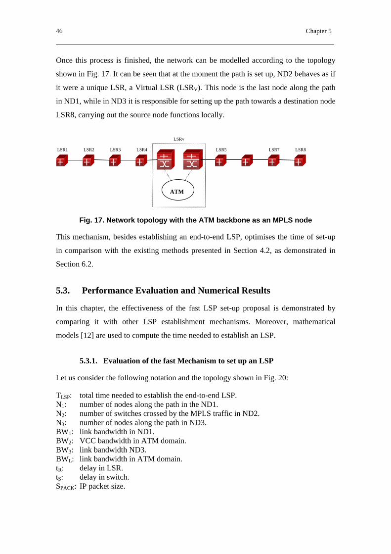
46 Chapter 5
Once this process is finished, the network can be modelled according to the topology
shown in Fig. 17. It can be seen that at the moment the path is set up, ND2 behaves as if
it were a unique LSR, a Virtual LSR (LSRV). This node is the last node along the path
in ND1, while in ND3 it is responsible for setting up the path towards a destination node
LSR8, carrying out the source node functions locally.
Fig. 17. Network topology with the ATM backbone as an MPLS node
This mechanism, besides establishing an end-to-end LSP, optimises the time of set-up
in comparison with the existing methods presented in Section 4.2, as demonstrated in
Section 6.2.
5.3. Performance Evaluation and Numerical Results
In this chapter, the effectiveness of the fast LSP set-up proposal is demonstrated by
comparing it with other LSP establishment mechanisms. Moreover, mathematical
models [12] are used to compute the time needed to establish an LSP.
5.3.1. Evaluation of the fast Mechanism to set up an LSP
Let us consider the following notation and the topology shown in Fig. 20:
TLSP: total time needed to establish the end-to-end LSP. N1: number of nodes along the path in the ND1. N2: number of switches crossed by the MPLS traffic in ND2. N3: number of nodes along the path in ND3. BW1: link bandwidth in ND1. BW2: VCC bandwidth in ATM domain. BW3: link bandwidth ND3. BWL: link bandwidth in ATM domain. tR: delay in LSR. tS: delay in switch. SPACK: IP packet size.
ATM
LSR1 LSR2 LSR3 LSR4 LSR5 LSR7 LSR8
LSRv
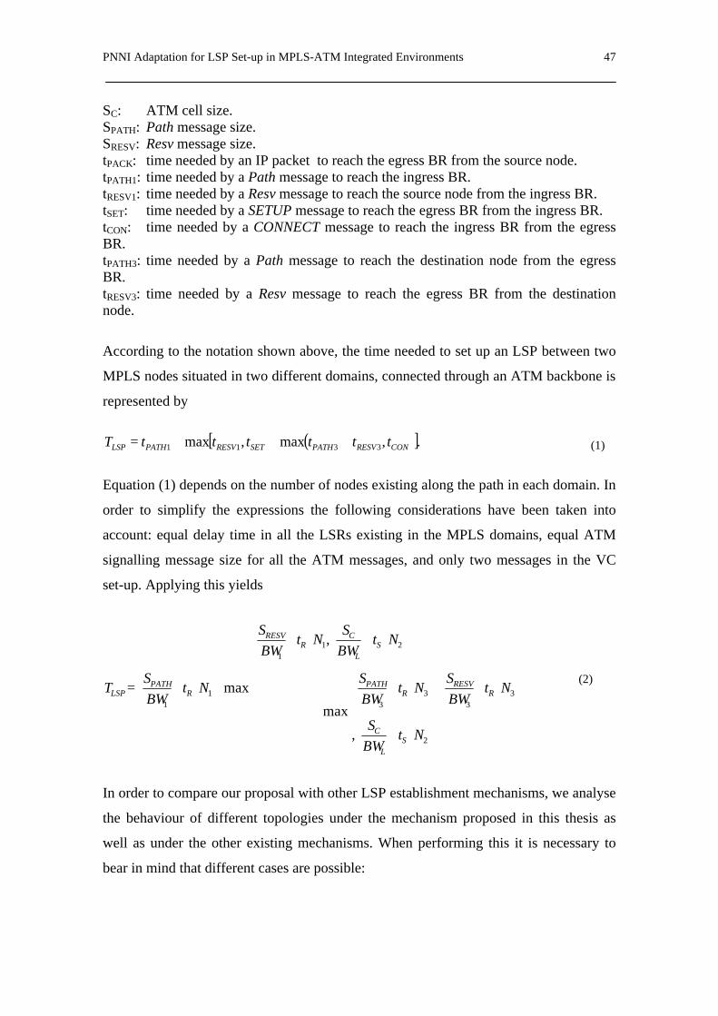
PNNI Adaptation for LSP Set-up in MPLS-ATM Integrated Environments 47
SC: ATM cell size. SPATH: Path message size. SRESV: Resv message size. tPACK: time needed by an IP packet to reach the egress BR from the source node. tPATH1: time needed by a Path message to reach the ingress BR. tRESV1: time needed by a Resv message to reach the source node from the ingress BR. tSET: time needed by a SETUP message to reach the egress BR from the ingress BR. tCON: time needed by a CONNECT message to reach the ingress BR from the egress BR. tPATH3: time needed by a Path message to reach the destination node from the egress BR. tRESV3: time needed by a Resv message to reach the egress BR from the destination node.
According to the notation shown above, the time needed to set up an LSP between two
MPLS nodes situated in two different domains, connected through an ATM backbone is
represented by
( )[ ].,max,max 3311 CONRESVPATHSETRESVPATHLSP ttttttT +++=
Equation (1) depends on the number of nodes existing along the path in each domain. In
order to simplify the expressions the following considerations have been taken into
account: equal delay time in all the LSRs existing in the MPLS domains, equal ATM
signalling message size for all the ATM messages, and only two messages in the VC
set-up. Applying this yields
+
++
+
+
+
+
+
+
+=
2
33
33
211
11
,
max
,
max
NtBWS
NtBWS
NtBWS
NtBWS
NtBWS
NtBWS
T
SL
C
RRESV
RPATH
SL
CR
RESV
RPATH
LSP
In order to compare our proposal with other LSP establishment mechanisms, we analyse
the behaviour of different topologies under the mechanism proposed in this thesis as
well as under the other existing mechanisms. When performing this it is necessary to
bear in mind that different cases are possible:
(1)
(2)
48 Chapter 5
- The ATM network is made of ATM LSRs as described in Section 4.2. In this
case, all the nodes are MPLS capable nodes and RSVP is used as the LDP. We
will simulate its behaviour as if the network were composed of three MPLS
domains. Equation (2) becomes
33
22
11
31
22
11
NtBWS
NtBWS
NtBWS
NtBWS
NtBWS
NtBWS
ttT
RRESV
SRESV
RRESV
RPATH
SPATH
RPATH
RESVPATHLSP
++
++
++
++
++
+=+=
- The ATM network does not implement PNNI, so the BRs do not have topology
information about the other BRs. One method to set up the LSP is proposed in
Section 4.2. Applying this to equation (2)
112
33
332
11
123321
NtBWS
BWS
NtBWS
NtBWS
BWS
NtBWS
ttttttT
RRESVRESV
RRESV
RPATHPATH
RPATH
RESVRESVTUNNELRESVPATHPATHTUNNELPATHLSP
+++
++
+++
+
=+++++= −−
As stated above, the path is simultaneously established in ND1, ND2 and ND3. Because
of this, the source node could send traffic before the LSP set-up process in the ATM
backbone or ND3 is complete. In order to test the effects produced by this bug, an
analysis has been performed. The different cases are:
The LSP is completely established when the source node starts sending traffic. The
condition is determined by the tRESV1 according to
( )CONRESVPATHSETRESV ttttt ,max 331 ++≥
And if the expression is
( )CONRESVPATHSETRESV ttttt ,max 331 ++<
Two possible cases appear, always considering that the backbone ATM VC is
established:
(3)
(4)
(5)
(6)
PNNI Adaptation for LSP Set-up in MPLS-ATM Integrated Environments 49
The first case can be represented by
331 RESVPATHPACKRESV tttt +≥+
In this case, as in the first case, the path is completely established before the traffic
flows along the path.
The second case can be represented by
331 RESVPATHPACKRESV tttt +<+
In this case, depending on the size of the first packet of MPLS traffic, it is possible that
the path would still be setting up in ND3 when the first packet flows from the source
node to the ingress BR. The end-to-end LSP will be completely established when the
first packet reaches the ingress BR if IP packet size satisfies the following condition:
133 RESVRESVPATHPACK tttt −+=
According to (9),
−
+−
+
++
= 211
33121
21 22 x
NtNtBWS
NtBW
SSBWBWN
BWBWS SR
RESVR
RESVPATHPACK
Once the analytical expressions have been obtained, the numerical results are computed
to compare the different methods explained above. In order to perform the graphic
representation, the following values will be constants: BW1=BW2= 2 Mbps, BWL=155
Mbps, tR=71µs, tS=10µs, SC=53 bytes, SPATH=112 bytes and SRESV=120 bytes. The rest
of the parameters will be modified to obtain a meaningful set of results from the
proposed method.
(7)
(8)
(10)
(9)

50 Chapter 5
Fig. 18. Speed-up (a) Fast LSP/LSR and (b) Fast LSP/RSVP TUNNEL
Fig. 19. Packet size for (a) BW2= 34Mbps and (b) BW2= 2Mbps
Firstly, the speed improvement, i.e. how many times faster our proposal is in setting up
the end-to-end LSP is computed compared to the reference mechanism. Therefore,
using equations (2) and (3), Fig. 18 (a) is obtained. Similarly, using equations (2) and
(4) the results shown in Fig. 18 (b) are obtained. In both cases, the BW2 is 34 Mbps.
Moreover, in order to reduce the complexity it is assumed that the VC between BR1 and
BR3 is already set up in the second case. The speed improvement is enhanced when N3
is increased to a maximum point, where N1 is double N3 (e.g., speed improvement =
1.54 for N1=10; i.e., 54% faster). From that maximum point on, when N3 increases in
value, the speed improvement decreases until reaching a stable value over 1. This shows
that the method proposed in this thesis allows an LSP to be set up faster than the other
methods.
Now the IP packet size required to fulfil the condition in equation (7) will be computed.
Using equation (10) with BW2=34 Mbps and BW2=2Mbps, results shown in Fig. 19 (a)
and (b) respectively are obtained. The worst case is produced when BW2 is 34 Mbps
1
1,1
1,2
1,3
1,4
1,5
1,6
1 2 3 4 5 6 7 8 9 10 11 12 13 14 15 16 17 18 19Number of nodes in N3
Spee
d-up
N1=20
N1=10
N1=2
1
1,1
1,2
1,3
1,4
1,5
1,6
2 3 4 5 6 7 8 9 10 11 12 13 14 15 16 17 18 19 20Number of nodes in N3
Spee
d-up
N1=20N1=10N1=2
01 0 02 0 03 0 04 0 05 0 06 0 07 0 08 0 09 0 0
1 0 0 01 1 0 01 2 0 01 3 0 01 4 0 01 5 0 01 6 0 01 7 0 01 8 0 01 9 0 02 0 0 02 1 0 0
0 1 2 3 4 5 6 7 8 9 1 0 1 1 1 2 1 3 1 4 1 5 1 6 1 7 1 8 1 9 2 0 2 1 2 2N u m b e r o f n o d e s i n N 3
byte
s
N 2 = 7 N 1 = 2 0
N 2 = 7 N 1 = 1 0
N 2 = 7 N 1 = 2
N 2 = 2 0 N 1 = 2 0
N 2 = 2 0 N 1 = 1 0
N 2 = 2 0 N 1 = 2
0
100
200
300
400
500
600
0 2 4 6 8 10 12 14 16 18 20
Number of nodes in N3
byte
s
N2=7 N1=20N2=7 N1=10N2=7 N1=2N2=20 N1=20N2=20 N1=10N2=20 N1=2
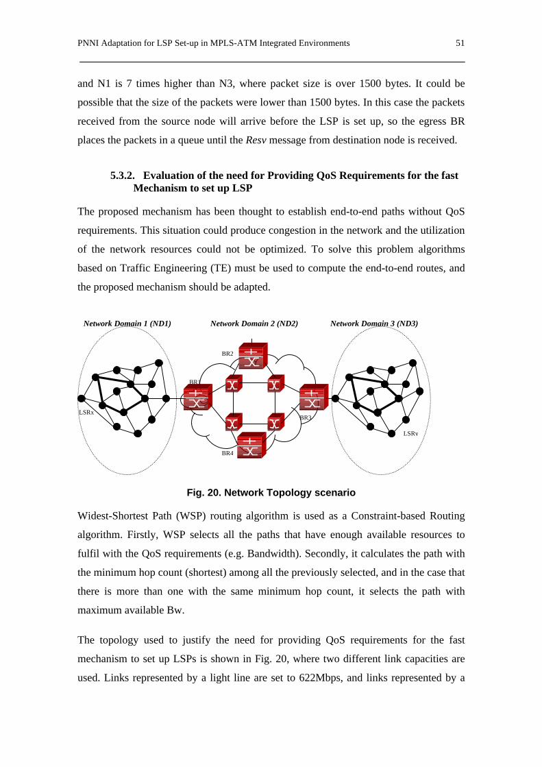
PNNI Adaptation for LSP Set-up in MPLS-ATM Integrated Environments 51
and N1 is 7 times higher than N3, where packet size is over 1500 bytes. It could be
possible that the size of the packets were lower than 1500 bytes. In this case the packets
received from the source node will arrive before the LSP is set up, so the egress BR
places the packets in a queue until the Resv message from destination node is received.
5.3.2. Evaluation of the need for Providing QoS Requirements for the fast Mechanism to set up LSP
The proposed mechanism has been thought to establish end-to-end paths without QoS
requirements. This situation could produce congestion in the network and the utilization
of the network resources could not be optimized. To solve this problem algorithms
based on Traffic Engineering (TE) must be used to compute the end-to-end routes, and
the proposed mechanism should be adapted.
Fig. 20. Network Topology scenario
Widest-Shortest Path (WSP) routing algorithm is used as a Constraint-based Routing
algorithm. Firstly, WSP selects all the paths that have enough available resources to
fulfil with the QoS requirements (e.g. Bandwidth). Secondly, it calculates the path with
the minimum hop count (shortest) among all the previously selected, and in the case that
there is more than one with the same minimum hop count, it selects the path with
maximum available Bw.
The topology used to justify the need for providing QoS requirements for the fast
mechanism to set up LSPs is shown in Fig. 20, where two different link capacities are
used. Links represented by a light line are set to 622Mbps, and links represented by a
LSRx
Network Domain 1 (ND1) Network Domain 2 (ND2) Network Domain 3 (ND3)
BR1
BR2
BR4
BR3
LSRy

52 Chapter 5
dark line are set to 2.5Gbps. The incoming requests arrive following a Poisson
distribution and the requested bandwidth is uniformly distributed between two ranges:
range 1 is between 0.5Mbps and 1Mbps; range 2 is between 1Mbps and 5Mbps. The
holding time is randomly distributed, with an average of 120 seconds. Finally, the
existing topology and available resources database in each border router is assumed to
be perfectly up-to-date. The experiments have been repeated 10 times with a 95%
confidence interval.
Results shown in Fig. 21 and Fig. 22 have been obtained using an extension of the ns2
simulator, MPLS_ns2. This results shows the LSP Blocking Ratio as a function of the
network load, understanding by blocked LSP the one that its last part computed in ND3
does not fulfil the QoS requirements. The value of the LSP Blocking Ratio is defined
according to the expression (11):
∑∑
∈
∈=
LSPtotii
LSPrejii
LSP
LSPRatioBlockingLSP
_
___
(11)
where rej_LSP is the set of blocked demands and tot_LSP is the set of total requested
LSPs.
The LSP Blocking Ratio is computed in two situations, referred to here as “Requested
Bw” (RBw) and “No Requested Bw” (NRBw):
- RBw: The LSP in ND3 is computed using a Constraint-based routing algorithm,
which uses the Bw required by the source node in ND1.
- NRBw: The LSP in ND3 is computed using a dynamic routing protocol, such as
Shortest Path First (SPF), which does not take into consideration any QoS
attributes.
Fig. 21 and Fig. 22 exhibit the gain of RBw over NRBw. The blocking is shown to be
lower when a QoS parameter is included in the path selection process.

PNNI Adaptation for LSP Set-up in MPLS-ATM Integrated Environments 53
Fig. 21. End-to-end LSP Blocking Ratio for range 1
Fig. 22. End-to-end LSP Blocking Ratio for range 2
Numerical results show that as the network load increases, the LSP Blocking Ratio also
increases, but the LSP Blocking Ratio may be reduced if the ingress node in ND3
knows the requested bandwidth. This reduction is between 0.3% and 3.4% according to
0
1
2
3
4
5
6
7
8
9
10
0 200 400 600 800 1000 1200 1400 1600 1800
Network load (LSPs)
LSP
Blo
ckin
g R
atio
(%)
RBwNRBw
0
1
2
3
4
5
6
7
0 200 400 600 800 1000 1200 1400 1600 1800
Network load (LSPs)
LSP
Blo
ckin
g R
atio
(%)
RBwNRBw

54 Chapter 5
both simulation results (Fig. 21 and Fig. 22). Therefore, a mechanism to transport QoS
information may be useful to reduce the amount of blocked LSPs due to the
impossibility of finding an LSP with the required Bw in network ND3 because a CR
algorithm is not used in ND3.

A Fast Mechanism to Establish an LSP with QoS Requirements 55
6. A Fast Mechanism to Establish an LSP with QoS Requirements
Traditionally, routes in an IP/MPLS domain are computed using a dynamic routing
protocol, such as a Shortest Path First (SPF). Since SPF does not take into consideration
any QoS attributes (e.g. available bandwidth), LSPs computed by this protocol could
lead the network to congestion situations. Using Traffic Engineering (TE) based routing
algorithms, congestion could be reduced and network resource utilization optimised.
One tool to achieve this is Constraint-based Routing (CR). The main goals of CR are
both selecting routes with certain QoS requirements and increasing network utilization.
This Chapter is devoted to applying the CR concept to our fast set-up mechanism
proposal to reduce the congestion effects in the different IP/MPLS domains composing
our scenario [13].
Consider the scenario shown in Fig. 20, assuming that the ATM backbone is able to set
up a VC between the ingress and egress BRs with the QoS values requested by the LDP
of ND1. For simplicity a single QoS parameter, the requested Bandwidth (Bw), is used
and the topology and available resources information are considered perfectly updated
in all the LSRs.
56 Chapter 6
Taking these factors into consideration, adding a new mechanism to provide QoS to our
fast LSP set-up proposal is proposed. The establishment of LSPs with Bw guarantees
works as follows:
1) An incoming LSP demand requests LSRx for a connection from LSRx to LSRy
with specific Bw guarantees.
2) LSRx computes the optimal route applying a Constraint-based Routing
algorithm using the bandwidth requested by the incoming LSP demand.
3) Once the CR algorithm has computed the path, the RSVP triggers a mechanism
to distribute labels. Thus, an RSVP Path message is sent to LSRy.
4) When the RSVP Path message reaches the ATM ingress BR1, it finds a label
associated to the destination IP address (in this case, a network IP address).
Then, an RSVP Resv message is returned to LSRx and a relation <label in, label
out> is set up in each LSR along the path to establish the LSP. Simultaneously,
the ingress BR1 triggers a SETUP message with the new GIT proposed in
Section 5.2 with a Generic Identifier Element containing the destination IP
address.
5) Once the SETUP message reaches the egress BR3, BR3 sends a RSVP Path.
Message to ND3. It is assumed that within the ATM network a VC with the
amount of Bw requested by LSRx can be set up between BR1 and BR3.
Simultaneously, the egress BR3 returns a CONNECT message to the ingress
BR1 to establish the corresponding ATM VC.
6) BR3 sends an RSVP Path message to LSRy and the ND3 ingress node computes
the LSP in ND3. The LSP set-up will be finished when the RSVP Resv returns
from LSRy to the egress BR3.
At the point in the process where the ND3 ingress node computes the path, it occurs that
the routing algorithm used to calculate the path to LSRy cannot be a CR algorithm,
because the received RSVP Path message form BR3 does not contain any QoS
parameters. Accordingly, a certain routing algorithm such as SPF should be used there.

A Fast Mechanism to Establish an LSP with QoS Requirements 57
Consequently, the LSP set up in ND3 can not guarantee the Bw requested by LSRx, and
in case of congestion in that LSP the loss of information would be unavoidable (no QoS
is provided).
The ideal case uses the same Constraint-based Routing algorithm in ND1 as in ND3.
For this to be possible, the egress ND3 ingress node has to know, in addition to the
destination IP address, the Bw requested by LSRx. To resolve this issue, this thesis
proposes adding a new Identifier Type in the Generic Identifier Element proposed in
Section 4.2. This can easily be done because an Identifier Related Standard/Application
may have multiple Identifier Types, and the number of identifiers is limited by the GIT
maximum length, 133 octets [10]. The following identifier definition is proposed:
Identifier Type = Resource, Identifier Length = 3 octets and Identifier Value =
requested BW in Mbps. The format of the new GIT is shown in Fig. 23.
Fig. 23. Generic Identifier with BW
In this way, when the RSVP Path message reaches the ingress BR1, both the destination
IP address and the Bw requested by LSRx are transferred to the ingress BR1. These
values are carried in the GIT and they are transported by the ATM SETUP message.
When this message reaches BR3, BR3 sends a RSVP Path messages to ND3 with the
requested Bw. Now, the ND3 ingress node has a value for a QoS parameter to compute
the path using a CR algorithm.
The solution proposed above has a minor drawback. When the end-to-end path cannot
be completed due to the impossibility of finding an LSP with the required Bw in ND3
(i.e., the LSP is blocked), then paths already set up in ND1 and ND2 have to be torn
Information Element Identifier = Generic Identifier transportIE (0x7F)
1
Ext Coding standard IE Instructions field 2 Length of contents of information element 3-4
Identifier related standard/application = MPLS (0x06) 5 Identifier type = Resource (0x02) 6 Identifier length = 4 octets (0x04) 7
IP/MPLS destination node address (4 octets)
11
Identifier type = Resource (0x02) 12 Identifier length = 4 octets (0x03) 13
Requested Bw (3 octets)
16

58 Chapter 6
down. In this situation, we have to take into consideration the cost of tearing down the
path in both domains. Therefore, In Section 6.2 we will evaluate the LSP blocking ratio
in ND3 to determine the effects produced by this drawback in our mechanism.
6.1. QoS Mechanism based on an Aggregated Traffic Engineering Database (ATED)
A solution to overcome this drawback consists of defining a mechanism able to
distribute topology and available resource information of the entire network between all
the MPLS networks interconnected through the ATM backbone. This information has to
be transported from ATM egress node (BR3) to ATM ingress node (BR1).Therefore,
the BR1 knows the ND3 network status before sending back the Resv message to source
node in ND1. If a route with the required QoS does not exist in ND3 the path in ND1 is
not established. One option is to transport a Traffic Engineering Database (TED)
containing a complete topology and available resource information about MPLS
network in ND3. The TED depends on the number of ND3 links and each link has
associated both the amount of bandwidth not yet reserved at each of eight MPLS
priority levels and a pair of node Identifiers [15]. In this way, the overhead introduced
in the ATM backbone due to the TED size depends on the MPLS network size in ND3.
Thus, in a large MPLS network the TED update process may produce a large signalling
overhead to guarantee that the TED information perfectly represents the network state.
We propose using the aggregation concept, which is used on hierarchical networks (e.g.
ATM PNNI networks [1]). It consists in reducing the amount of topology and available
resource information in each Peer Group that composing the network. Taking into
consideration this concept, we may reduce the amount of topology information in an
IP/MPLS network (i.e. ND3) using an aggregation scheme.
Several aggregation schemes have been proposed, analysed and compared [36][38]. We
propose adapting two aggregation schemes, namely Full Mesh Aggregation (FMA)
Scheme and Asymmetric Simple Aggregation (ASA) Scheme defined in [37]. This
adaptation consists in using the MPLS TE parameters [15] to generate an Aggregated
Traffic Engineering Database (ATED). We only consider the unreserved Bandwidth as
a QoS parameter in order to simplify the aggregation scheme definition.

A Fast Mechanism to Establish an LSP with QoS Requirements 59
The Full Mesh Aggregation Scheme works as follows:
1. Select all border nodes of the network. Consider a border node as ingress and egress node (Fig. 24 (1)).
2. Compute all the routes between an ingress node and an egress node (Fig. 24 (2)).
3. Select the path that provides the best QoS (Fig. 24 (3)).
4. Repeat steps 2 and 3 for each pair of ingress/egress nodes.
Fig. 24. Steps for an FMA Scheme
The aggregated unreserved bandwidth for each MPLS priority level computed by the
FMA scheme is defined as follows:
Where
- ijkB is the aggregated unreserved bandwidth for the k priority level allocated to a pair
of border nodes (ingress node i and egress node j).
- i,j are an ingress and an egress node of the network.
- Rij is a path between i and j.
- l is a link of the path Rij.
(1) (2) (3)
A
B
C
A
B A B
[ ]
=
∈≠∀=)(minmax
,8...1lBB kRljiRk
ijk
ijij
(12)
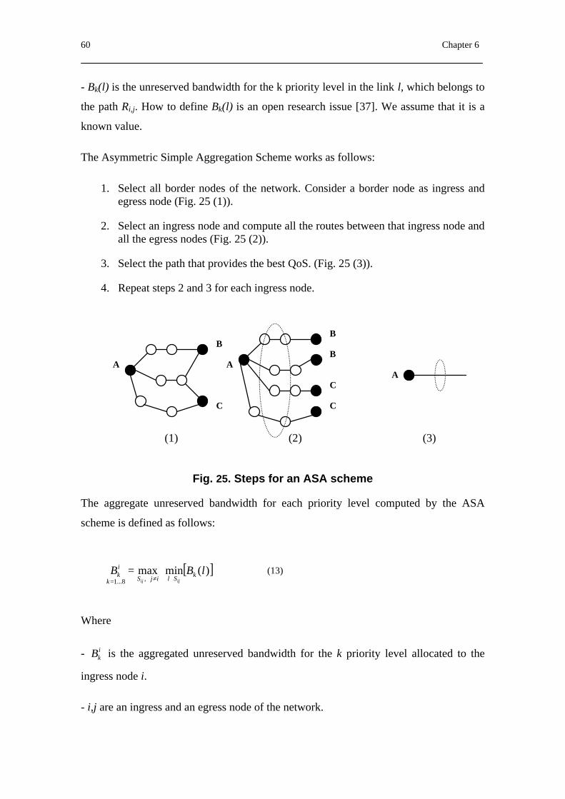
60 Chapter 6
- Bk(l) is the unreserved bandwidth for the k priority level in the link l, which belongs to
the path Ri,j. How to define Bk(l) is an open research issue [37]. We assume that it is a
known value.
The Asymmetric Simple Aggregation Scheme works as follows:
1. Select all border nodes of the network. Consider a border node as ingress and egress node (Fig. 25 (1)).
2. Select an ingress node and compute all the routes between that ingress node and all the egress nodes (Fig. 25 (2)).
3. Select the path that provides the best QoS. (Fig. 25 (3)).
4. Repeat steps 2 and 3 for each ingress node.
Fig. 25. Steps for an ASA scheme
The aggregate unreserved bandwidth for each priority level computed by the ASA
scheme is defined as follows:
Where
- ikB is the aggregated unreserved bandwidth for the k priority level allocated to the
ingress node i.
- i,j are an ingress and an egress node of the network.
(1) (2) (3)
A
B
C
A
B
B
C
C
A
[ ]
=
∈≠∀=)(minmax
,8...1lBB kSlijSk
ik
ijij
(13)

A Fast Mechanism to Establish an LSP with QoS Requirements 61
- Sij is a path between i and any j.
- l is a link of the path Sij.
- Bk(l) is the unreserved bandwidth for the k priority level in the link l, which belongs
the path Rij. We also assume that it is a known value.
In order to transport an ATED through the ATM backbone, a new PAR PTSE named
PAR MPLS ATED Service Definition IG is defined. The element format is shown in
Fig. 26. Thus, the process to establish the LSP end-to-end is as follows:
1. Each BR uses the Proxy PAR client to register the MPLS information and the
ATED associated with the IP/MPLS Network connected to the BR.
2. The Proxy PAR server floods PTSEs throughout the ATM backbone. Once the
flooded information reaches all the BRs, each one uses the Proxy PAR client to
obtain that information.
Fig. 26. PAR MPLS ATED Services definition IG
3. LSRx computes the path using the ND1 ATED and sends an RSVP Path
message to ND3. The RSVP path message contains the Explicit Routing Object
(ERO), which registers the route.
C IG Name Nested in768 PAR Service IG PTSE (64)776 PAR VPN ID IG PAR Service IG (768)784 PAR IPv4 Service Definition IG PAR VPN ID IG (776) / PAR
Service IG (768)
792 PAR MPLS Services Definition IG PAR Services IG (768)
800 PAR IPv4 OSPF Service DefinitionIG
PAR IPv4 Service Definition IG(784)
801 PAR IPv4 MOSPF Service DefinitionIG
PAR IPv4 Service Definition IG(784)
802 PAR IPv4 BGP4 Service DefinitionIG
PAR IPv4 Service Definition IG(784)
803 PAR IPv4 DNS Service Definition IG PAR IPv4 Service Definition IG(784)
804 PAR IPv4 PIM-SM ServiceDefinition IG
PAR IPv4 Service Definition IG(784)
805 PAR MPLS TED Servicesdefinition IG
PAR MPLS Services DefinitionIG (792)
Offset Size (bytes) Name Function/Description 0 2 Type Type=792 (PAR MPLS Service Definition IG) 2 2 Length
4 4 IP address The IP address or IP address prefix Dest. 8 32 ATED
40 8 Service Mask Bitmask of registered services.

62 Chapter 6
4. The RSVP Path message reaches BR1, which checks the ATED to verify
whether a path with the required Bw exists on ND3. If there is no available path
with the required Bw, then the connection will be refused. Otherwise, the set-up
process follows.
5. The ingress BR1 triggers a SETUP message to set up a VC and sends an RSVP
Resv message to LSRx with the required label.
6. When the SETUP message reaches the egress BR3, BR3 sends an RSVP Path
message to ND3. ND3 ingress node computes last part of the end-to-end path in
ND3. The LSP set-up will be finished when the RSVP Resv returns from LSRy
to the egress BR3. Simultaneously, the egress BR3 returns a CONNECT
message to the ingress BR1 to establish the corresponding ATM VC.
Since Network Operators commonly do not like sharing such an amount of information
with other Network Operators, this solution may be applied when the MPLS networks
belong to different administrative domains because the ATED information is a summary
of the complete topology and resource information of ND3. It is assumed that the
ATEDs are always updated. This means that the ND3 ATED has to be flooded
throughout the ATM backbone every time the update process modifies the ATED. This
increases overhead in the backbone, and it could be a problem in large networks.
Consequently, a trade-off between the ATED accuracy and overhead in the ATM
backbone has to be considered. The impact of possible network information inaccuracy
in the mechanisms proposed in this thesis will be a subject for further studies. Finally,
we propose using a QoS routing algorithm, proposed in [14], to reduce the LSP
blocking probability resulting from selecting the path under inaccurate routing
information.
6.2. Performance evaluation and numerical results
An LSP is blocked when the route computed in the source node by a CR algorithm can
not be set up because a link of the path does not fulfil the QoS requirements. Traditional
mechanisms to set up an LSP solve this problem by triggering either a crankback
process (e.g. in ATM networks) or a time-out (e.g. in IP/MPLS networks), which avoid
setting up an LSP without the QoS requirements requested by the connection. On the

A Fast Mechanism to Establish an LSP with QoS Requirements 63
other hand, in the mechanism proposed in this thesis the LSP blocking problem must be
taken into especial consideration. This mechanism is based on a parallel process used to
establish an end-to-end path in order to reduce the set-up time. This parallel process
consists in establishing a part of the total path in each network domain at the same time.
In this situation, a part of the total path could be established in ND1 but ND3 could not
establish the last part of the path because does not fulfill the QoS requirements. As a
consequence, a Teardown process must be triggered form destination network domain
to source network domain to avoid sending traffic from the source node. Depending on
the network size (number of nodes) the teardown message could not arrive on time. This
situation must be avoided as far a possible. Specifically, the LSP blocking problem
occurs in the scenario depicted in Fig. 20 as follows.
Consider that the first segment of the LSP (in ND1) and the VC through the ATM
backbone has been established. Whereas, last part of the LSP in ND3 cannot be
stablished because an LSP with the required Bw does not exist. Then the end-to-end
path cannot be completed due to the impossibility of finding an LSP with the required
Bw in network ND3. Thus, a teardown process must be triggered to tear down the
established path in ND1 and ND2. The cost of this process will depend on the LSP
Blocking Ratio produced in ND3.
The solution presented in Section 6.1 reduces the LSP Blocking Ratio, since BR1
checks the ND3 ATED to know whether a path with the required Bw exists in ND3. If
the path exists in ND3, the process to set up the total path follows as mentioned above.
Otherwise, the path is not established in ND1. As a consequence of applying this
solution, the number of teardown actions in ND1 is also reduced. On the other hand, it
must be taken into account that transporting the ND3 ATED throughout the ATM
backbone produces signalling information overhead. This overhead depends on the
ATED size and the update mechanism.
Consider again the scenario shown in Fig. 20 and assume that the egress BR3 has a
Traffic Engineering Database (no aggregated TED) where the ND3 topology and
available resource information is kept. There are 15 nodes, 27 links and 5 border nodes
(ingress and egress) in each IP/MPLS network topology. The TED is assumed to have
been made using “extended link attributes” [15], so its size depends on the number of

64 Chapter 6
ND3 links. Each link has associated the amount of bandwidth not yet reserved at each
of eight priority levels (32 bytes) and a number of node IDs (8 bytes). Therefore, in our
scenario the TED size is over 1Kbyte. On the other hand, using an aggregation scheme
the size of the TED is as follows. The Aggregated TED (ATED) based on the FMA
scheme depends on the number of routes between all the border nodes. Therefore, the
ND3 ATED contains information about the 4 routes existing between the ingress node
and the rest of the border nodes. Thus, the ATED size is 192 bytes. The ATED based on
ASA scheme depend on the number of border nodes. In particular, the ND3 ATED,
which will be transported across the ATM backbone, contains the information related
with the ingress node that is directly connected to the backbone. Therefore, the ATED
size is 32 bytes.
Fig. 20 shows the topology used to simulate the behaviour of the aggregation schemes.
Two different link capacities are used. Links represented by a light line are set to
622Mbps, and links represented by a dark line are set to 2.5Gbps. The incoming
requests arrive following a Poisson distribution and the requested bandwidth is
uniformly distributed between two ranges: range 1 is between 0.5Mbps and 1Mbps;
range 2 is between 1Mbps and 5Mbps. The holding time is randomly distributed, with
an average of 120 seconds. Finally, the existing topology and available resources
database in each border router is assumed to be perfectly up-to-date. The experiments
have been repeated 10 times with a 95% confidence interval.

A Fast Mechanism to Establish an LSP with QoS Requirements 65
Fig. 27. Comparison between FMA and ASA ATED size
In general, the FMA scheme performs an ATED larger than the ASA scheme. However,
the information of the FMA ATED is more accurate that the information contained in
the ASA ATED. Fig. 27 compares the ATED size (number of entries on the database)
for both aggregation schemes and Fig. 28 shows the inaccuracy effects, that is, the LSP
blocking ratio due to the ATED inaccuracy. The worst case is when a TED is not
transported from ND3 to ND1. The best case occurs when an aggregation scheme is not
applied to the TED. In this situation, BR1 knows the complete topology and available
resources information of ND3 and may decide to establish the total path. Between both
cases are the aggregation options. We observe that the ASA scheme reduces the LSP
Blocking Ratio more than the FMA. As mentioned above, it is due to the larger
inaccuracy introduced by the ASA scheme.
0
10
20
30
40
50
60
0 2 4 6 8 10
Number of border nodes
Nu
mb
er o
f A
TE
D e
ntr
ies
FMA schemeASA scheme
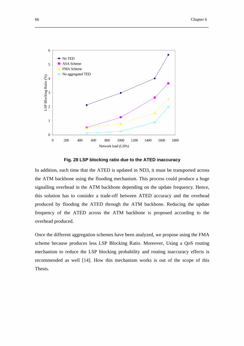
66 Chapter 6
Fig. 28 LSP blocking ratio due to the ATED inaccuracy
In addition, each time that the ATED is updated in ND3, it must be transported across
the ATM backbone using the flooding mechanism. This process could produce a huge
signalling overhead in the ATM backbone depending on the update frequency. Hence,
this solution has to consider a trade-off between ATED accuracy and the overhead
produced by flooding the ATED through the ATM backbone. Reducing the update
frequency of the ATED across the ATM backbone is proposed according to the
overhead produced.
Once the different aggregation schemes have been analyzed, we propose using the FMA
scheme because produces less LSP Blocking Ratio. Moreover, Using a QoS routing
mechanism to reduce the LSP blocking probability and routing inaccuracy effects is
recommended as well [14]. How this mechanism works is out of the scope of this
Thesis.
0
1
2
3
4
5
6
0 200 400 600 800 1000 1200 1400 1600 1800
Network load (LSPs)
LSP
Blo
ckin
g R
atio
(%)
No TEDASA SchemeFMA SchemeNo aggregated TED

67
PART III
PNNI BASED CONTROL PLANE FOR ASON
The goal of this Part is to define Optical PNNI (O-PNNI) as an adaptation of the ATM-
PNNI protocols, and to analyse the potential usage of the O-PNNI and GMPLS models,
looking at pros and cons of each approach. The methodology adopted towards rendering
the enhanced PNNI protocols calls for reviewing PNNI, along with ASON
recommendations, in order to determine the set of PNNI features that require adaptation
for supporting an ASON control plane. Having identified these features, we obtain and
present the appropriate solutions. This methodology has been followed in two parallel
directions: first towards adapting the routing protocol and next towards a preliminary
adaptation of ASON signalling features and mechanisms that are not supported by
PNNI.


Recommendations for ASON and PNNI Standard Features 69
7. Recommendations for ASON and PNNI Standard Features
7.1. Introduction
PNNI has the potential to become a protocol supporting the ASON control plane, since
it implements many features that are essential to the ASON control plane, according to
relevant recommendations for ASONs [2] [18] [21]. A characteristic set of such
features, which are both required and useful in an ASON, follows:
- High routing scalability with multiple levels of hierarchy (up to 104).
- Automatic topological discovery and resource discovery.
- Constraint-based source routing using cost, capacity, link constraints,
propagation delay constraints, etc. PNNI supports rerouting around failed
components at connection set-up (crankback).
- Call Admission Control (CAC).
- Traffic management functions.
- PVC, SVC and Soft PVC support. Allows the set-up of permanent and switched
connections. Additionally, so-called soft-permanent virtual connections are
implemented. At the UNI, the connection is permanent (manually established),
but inside the network the connection is switched. This feature in

70 Chapter 7
ASONs/ASTNs may reduce security problems at administration boundaries and
may help on the migration path to the ASON/ASTN architecture (facilitating a
mixture of ASON/ASTN-capable and non-ASON/ASTN-capable equipment).
- Resilience functions in case of failures (pre-planned or on-demand). “Slow” re-
rerouting for optimisation purposes (make before break).
- Supports Organization, Administration and Maintenance (OAM) information
element.
- Supports connection-tracing functions.
- Point-to-multipoint connections supported (G.807 requirement).
- Supports switched connections, soft-permanent connections, unidirectional
connections, bi-directional connections, and point to multipoint connections.
- Supports separation between signalling and transport networks.
- Scalability, reliability and efficiency, and support for protection and restoration
mechanisms.
- Support for Class of Service (CoS) and QoS.
PNNI consists of two separable parts, a signalling protocol and a routing protocol. It
therefore allows the distribution of signalling and routing to be different where required.
PNNI also allows a signalling option to be employed while routing is provided by a
centralized management network, thereby allowing reuse of existing network
management investment if necessary. It is not necessary to use the ATM transport plane
with the PNNI protocol: indeed the ATM Adaptation Layer (AAL) could be replaced by
an IP transport plane, as well as Ethernet or point-to-point.
7.2. ITU-T Recommendations for ASON
7.2.1. ASON Control Plane Components
An ASON is composed of the following components that provide specific functions,
including that of route determination and signalling:
Recommendations for ASON and PNNI Standard Features 71
Connection controller (CC) component. The connection controller is responsible for
coordination among the Link Resource Manager, Routing Controller, and both peer and
subordinate Connection Controllers for the purpose of the management and supervision
of connection set-ups, releases and the modification of connection parameters for
existing connections.
In addition, the CC component provides a Connection Controller Interface (CCI). This
is an interface between a subnetwork in the transport plane and the control plane. It is
used by control components to direct the creation, modification, and deletion of
Subnetwork Connections (SNCs).
Routing Controller (RC) component. The role of the routing controller is to respond
to requests from connection controllers for path (route) information needed to set up
connections. This information can vary from end-to-end (e.g., source routing) to next
hop. The RC also responds to requests for topology (Subnetwork Paths (SNPs) and their
abstractions) information for network management purposes.
Link resource manager (LRMA and LRMZ) component. The LRM components are
responsible for the management of an SNPP link; including the allocation and release of
SNP link connections, and providing topology and status information. Two LRM
components are used, LRMA and LRMZ. A pair of LRMA and LRMZ components,
one managing each end of the link, manages an SNPP link. Requests to allocate SNP
link connections are only directed to the LRMA.
Traffic Policing (TP) component. The role of this component is to check that the
incoming user connection is sending traffic according to the parameters agreed upon.
Where a connection violates the agreed parameters, the TP may instigate measures to
correct the situation.
Call Controller components. Calls are controlled by means of call controllers. There
are two types of call controller components:
- A calling/called party call controller. This is associated with an endpoint of a
call and may be co-located with end systems, or located remotely acting as a
72 Chapter 7
proxy on behalf of end systems. This controller acts in one or both of two roles:
one to support the calling party and the other to support the called party.
- A network call controller. A network call controller assumes two roles, one for
support of the calling party and the other to support the called party.
Protocol controller (PC) components. The Protocol Controller maps the abstract
interface parameters of the control components into messages that are carried by a
protocol to support interconnection via an interface. Signalling primitives are passed
between the connection controller and the protocol controller and the actual signalling
messages are passed between the two protocol controllers.
Component Interaction. In order to control a connection it is necessary for a number
of components to interact.
Three basic forms of algorithm for dynamic path control can be distinguished
depending on the routing used: hierarchical, source and step-by-step routing. The
different forms of path control result in a different distribution of components between
nodes, relationships between these connection controllers and, in general, different
control plane operations concerning signalling.
7.2.2. Routing
Recommendation G.807 [21] defines several logical interfaces or reference points.
These reference points are the User Network Interface (UNI), the Internal Network-to-
Network Interface (I-NNI) and the External Network-to-Network Interface (E-NNI).
The I-NNI should perform signalling and routing functions. Routing is the control plane
function used to select paths in order to set up connections across one or several carrier
networks. This function associates incoming labels with outgoing labels. In this context,
a label could be a wavelength, a virtual path identifier, etc. The labels are used to
identify individual connections within a link; in order to establish this association, the
topology and link state must be known. The topology has to be automatically
discovered by the control plane functions using a dissemination mechanism. However,
advertising information regarding individual nodes and links throughout a large network
may result in high overheads that limit network performance. A single carrier optical

Recommendations for ASON and PNNI Standard Features 73
network may consist of hundreds of network nodes, with each node containing more
than one thousand physical ports. An appropriate ASON routing protocol has to be
scalable enough for this network size. Some approaches may be used to achieve
scalability, such as hierarchical routing, link bundling, and classification of link state
information into static and dynamic information.
Thus, routing functions include two parts:
- Network information dissemination among nodes and networks, taking into
account scalability aspects.
- Constraint based path computation, which depends on the accuracy of available
network information, input requirements and the internal computation algorithm.
Network information dissemination. A routing protocol is required to advertise
network topology and available resource information within and/or between domains.
Nodes, which are responsible for computing the path, need to maintain an optical
network topology representation, including link resources and link switching
capabilities. In order to achieve scalability, the following approaches are used:
- Hierarchical routing. Recommendation G.8080 [2] defines a routing area as a set
of subnetworks. A routing area may contain smaller routing areas interconnected
by Subnetwork Termination Point Pool (SNPP) links. Hierarchical routing uses
a hierarchical structure based on a decomposition of the network into a
subnetwork hierarchy. Each subnetwork has its own dynamic connection
control, which knows its own topology but does not know the topology of other
subnetworks belonging to either the same hierarchical level or different levels.
- Link bundling. This aims at minimizing global information by keeping
information and decision-making local where possible.
- Classification of the link state into static and dynamic information. This selects
the information that has to be advertised, and when to send it.

74 Chapter 7
A trade-off between network representation accuracy and routing information
summarization is required. The election of the optimal path will be affected by network
representation inaccuracy.
Constraint based path computation. ASON is a network based on a connection-
oriented path. The consequences of an incorrect path computation will affect the
connection for the entire time that is in use. Thus, path computation is a critical aspect
and has to be carefully performed. Path computation depends on:
- Available information. This is the result of the dissemination process.
- Internal computation algorithm. This could be standardized or vendor/carrier
proprietary.
- Input requirements. These include source and destination, along with the
requested routing constraints and Bandwidth.
- Diversity. Many times multiple optical connections are established between the
same end points. A possible constraint on these connections is that they could be
required to be diversely routed, in the sense of link-disjoint, node-disjoint, or
SRLG (Shared Risk Link Group) disjoint.
- Inclusion in or exclusion from a hop list.
- Service provider list.
- Quality of Service requirements.
- Network constraints. Connectivity, Available Bandwidth, Wavelength continuity
and Physical (linear and non-linear impairments) impacts in all-optical
networks.
7.2.3. Addressing
The need for addresses for various entities in the ASON control plane is described in
document [2]. Firstly, the UNI Transport Resource requires an address to specify the
destination, and the Network Call Control requires an address for signalling. Secondly,
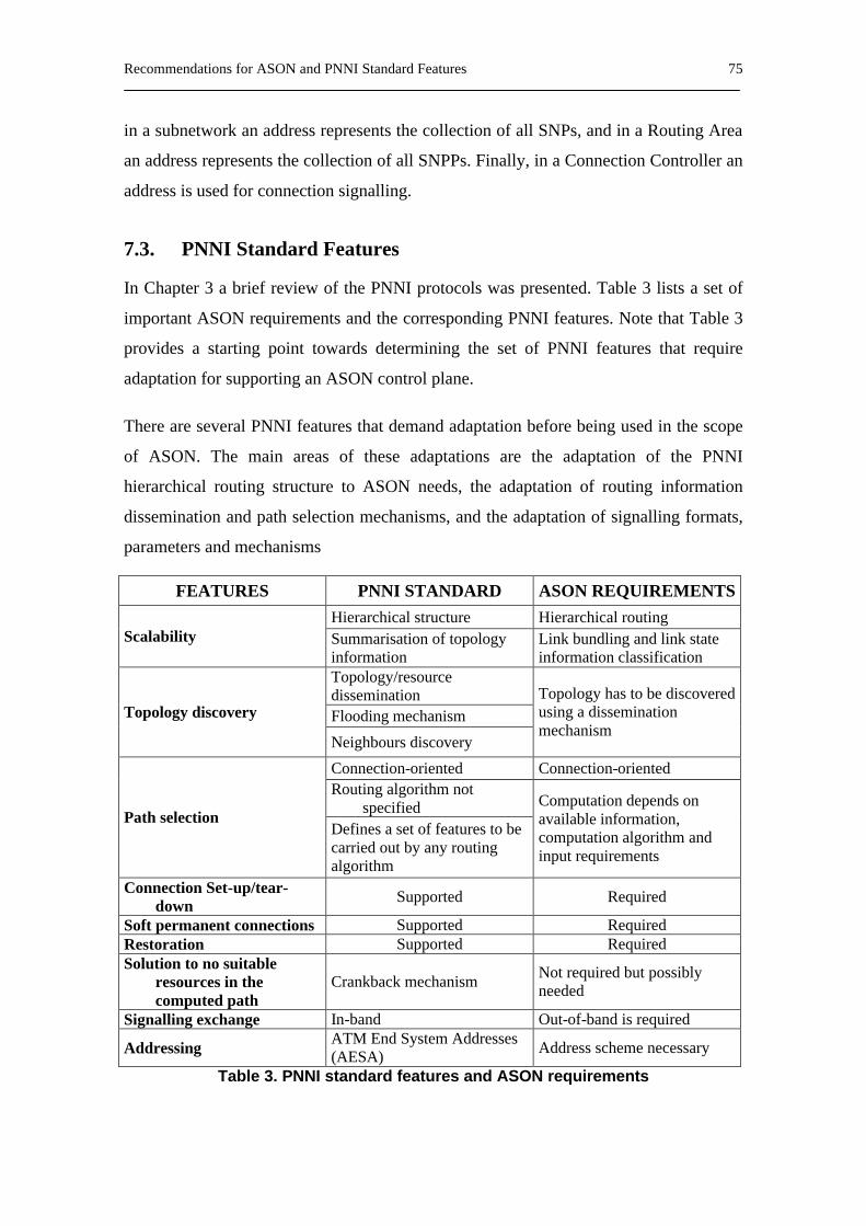
Recommendations for ASON and PNNI Standard Features 75
in a subnetwork an address represents the collection of all SNPs, and in a Routing Area
an address represents the collection of all SNPPs. Finally, in a Connection Controller an
address is used for connection signalling.
7.3. PNNI Standard Features
In Chapter 3 a brief review of the PNNI protocols was presented. Table 3 lists a set of
important ASON requirements and the corresponding PNNI features. Note that Table 3
provides a starting point towards determining the set of PNNI features that require
adaptation for supporting an ASON control plane.
There are several PNNI features that demand adaptation before being used in the scope
of ASON. The main areas of these adaptations are the adaptation of the PNNI
hierarchical routing structure to ASON needs, the adaptation of routing information
dissemination and path selection mechanisms, and the adaptation of signalling formats,
parameters and mechanisms
FEATURES PNNI STANDARD ASON REQUIREMENTS Hierarchical structure Hierarchical routing
Scalability Summarisation of topology information
Link bundling and link state information classification
Topology/resource dissemination Flooding mechanism Topology discovery
Neighbours discovery
Topology has to be discovered using a dissemination mechanism
Connection-oriented Connection-oriented Routing algorithm not
specified Path selection
Defines a set of features to be carried out by any routing algorithm
Computation depends on available information, computation algorithm and input requirements
Connection Set-up/tear-down Supported Required
Soft permanent connections Supported Required Restoration Supported Required Solution to no suitable
resources in the computed path
Crankback mechanism Not required but possibly needed
Signalling exchange In-band Out-of-band is required
Addressing ATM End System Addresses (AESA) Address scheme necessary
Table 3. PNNI standard features and ASON requirements

PONNI: A Routing Protocol for ASON 77
8. PONNI: A Routing Protocol for ASON
8.1. Introduction
In recent years the introduction of high capacity and reliable transport networks is being
necessary in order to cover the needs of Internet traffic demands. New incoming
Internet applications increasingly request greater capacity and guarantees of traffic
delivery. Optical Transport Networks (OTN) with automatic switching capabilities
(ASON, Automatic Switching Optical Networks) appear as a potential solution to cope
with such a situation.
ASON has to include a Control Plane able to provide features such as Traffic
Engineering. One of the essential components of this Control Plane is the routing
algorithm, which has to compute a proper route to the incoming connection demands,
for which it has to take into consideration the available network resources. In this way,
the routing algorithm requires a Traffic Engineering Database (TED) in order to obtain
information on topology and available resources, which must be updated when a change
of the topology or the resource utilization is produced. In order that the TED can be
updated, the control plane has to provide a flexible, fast and reliable mechanism to
disseminate the topology and the available resource information throughout the
network. In order to support such a mechanism, an Optical NNI (O-NNI) has to be
defined for ASON.
78 Chapter 8
For some time it seemed clear that such an O-NNI would be based on the GMPLS
paradigm. Nevertheless recently the idea of an O-NNI based on the ATM PNNI
paradigm is gaining partisans. Solutions based on the GMPLS paradigm only consider
typical Internet protocols such as link state based Internet Gateway Protocols (IGPs). In
this thesis, we deal with a potential use for this purpose of an adaptation of the part of
the ATM PNNI protocol [1] designed for routing functions. The resulting adapted
protocol is called Private Optical NNI (PONNI)[16].
PONNI may be a viable solution because while, for instance, OSPF has to be modified
in order to achieve the capabilities needed to distribute both internal and external
information on the available resources (e.g. remaining bandwidth, wavelengths, etc.),
PNNI has these capabilities by nature. PONNI is defined in the context of pursuing the
compatibility between both the ATM PNNI and GMPLS, using the best of each
approach. Currently, we only deal with two of the ASON control plane procedures,
namely the Routing and the Signalling. Regarding the signalling, we assume to use the
GMPLS signalling such as is recommended by the IETF.
This Chapter is a starting point to define a Private NNI as an adaptation of the ATM
PNNI protocol for ASON. We focus on the Routing procedure used in IP over ASON
environments. In consistence with this, the following issues are taken into account: 1)
Providing to ASON with a hierarchical structure in order to assure the scalability for
large worldwide networks. 2) Exchange Optical Information. Each node exchanges
Hello messages with its neighbours in order to determine what is its local state
information. This information includes a node Identifier, a subnetwork Identifier and the
status of the links between the node and its neighbours. 3) Exchange Non-Optical
Information: PONNI Augmented Routing (POAR), which allows information about
non-ASON client networks to be distributed in an ASON.
Although in this Chapter we consider that the optical transport network clients are IP
routers, for the PONNI definition it is also assumed that the protocol can be used for
other type of clients such as ATM, SDH, etc.
The remainder of this Chapter is organized as follows: Section 8.2 is devoted to define a
hierarchical structure for ASON. Section 8.3 deals with the process of disseminating

PONNI: A Routing Protocol for ASON 79
topology information throughout the ASON. Section 8.4 proposed a new source-based
QoS routing, which is composed of two aggregation schemes, an update policy and a
routing algorithm. Finally, in Section 5, a case study based on applying the PONNI
protocol to a hypothetical configuration of the Pan-European Network is discussed.
8.2. Hierarchical Structure
PNNI hierarchy can be directly applied to ASONs in order to ensure that the protocol
for distributing topology information scales well for worldwide optical networks. Next,
a PONNI hierarchy based on the ATM-PNNI hierarchy is presented.
A routing area of an ASON should be composed of a set of subnetworks, which have to
contain physical nodes with similar features. The subnetwork nodes should exchange
topology and resource information among themselves in order to maintain an identical
view of the subnetwork. This information should be contained in a Routing Controller
(RC) component, which will respond both to requests from connection controllers (CC)
for path information needed to set up connections and to requests for topology
information from hierarchical mechanisms. Each subnetwork has to be identified by a
subnetwork Identifier (sID). Since GMPLS uses IP addresses, we propose using the first
72 bits of the IPv6 addresses (i.e. the Format prefix, Top-level Aggregation Identifier,
Reserved, Next-level Aggregation Identifier and Site-level Aggregation Identifier
fields) [40] as sID (Fig. 29). Thereby, sID is a prefix of IPv6 addresses such that the
organisation that administer the subnetwork has assignment authority over that prefix.
Therefore, sID will be encoded using 9 bytes, 1 byte (8 bits) as a level indicator plus by
8 bytes (64 bits) of an identifier information field. The value of the level indicator will
be between zero and 64. The value sent in the identifier information field will be
encoded with the 64-n right-most bits set to zero, where n will be the level.
Moreover, each OXC has to have assigned a node Identifier (nID), which will be
composed of 8 bytes distributed as follows: the first byte (level indicator) will specify
the level of the subnetwork where the node will be contained. The second byte will take
value 100 in order to help to distinguish between physical node and LSN. The
remainder of the node ID will contain the 16 bytes IPv6 address of the system
represented by the node.
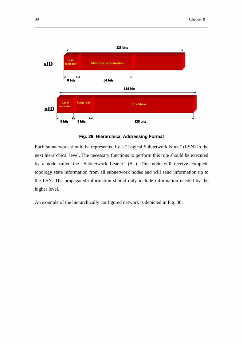
80 Chapter 8
Fig. 29. Hierarchical Addressing Format
Each subnetwork should be represented by a “Logical Subnetwork Node” (LSN) in the
next hierarchical level. The necessary functions to perform this role should be executed
by a node called the “Subnetwork Leader” (SL). This node will receive complete
topology state information from all subnetwork nodes and will send information up to
the LSN. The propagated information should only include information needed by the
higher level.
An example of the hierarchically configured network is depicted in Fig. 30.
128 bits
64 bits8 bits
Level indicator Identifier information
Level indicator
8 bits 8 bits 128 bits
IP addressValue=100
144 bits
sIDsID
nIDnID
128 bits
64 bits8 bits
Level indicator Identifier information
128 bits
64 bits8 bits
Level indicator Identifier information
Level indicator Identifier information
Level indicator
8 bits 8 bits 128 bits
IP addressValue=100
144 bits
Level indicator
8 bits 8 bits 128 bits
IP addressValue=100
144 bits
sIDsID
nIDnID
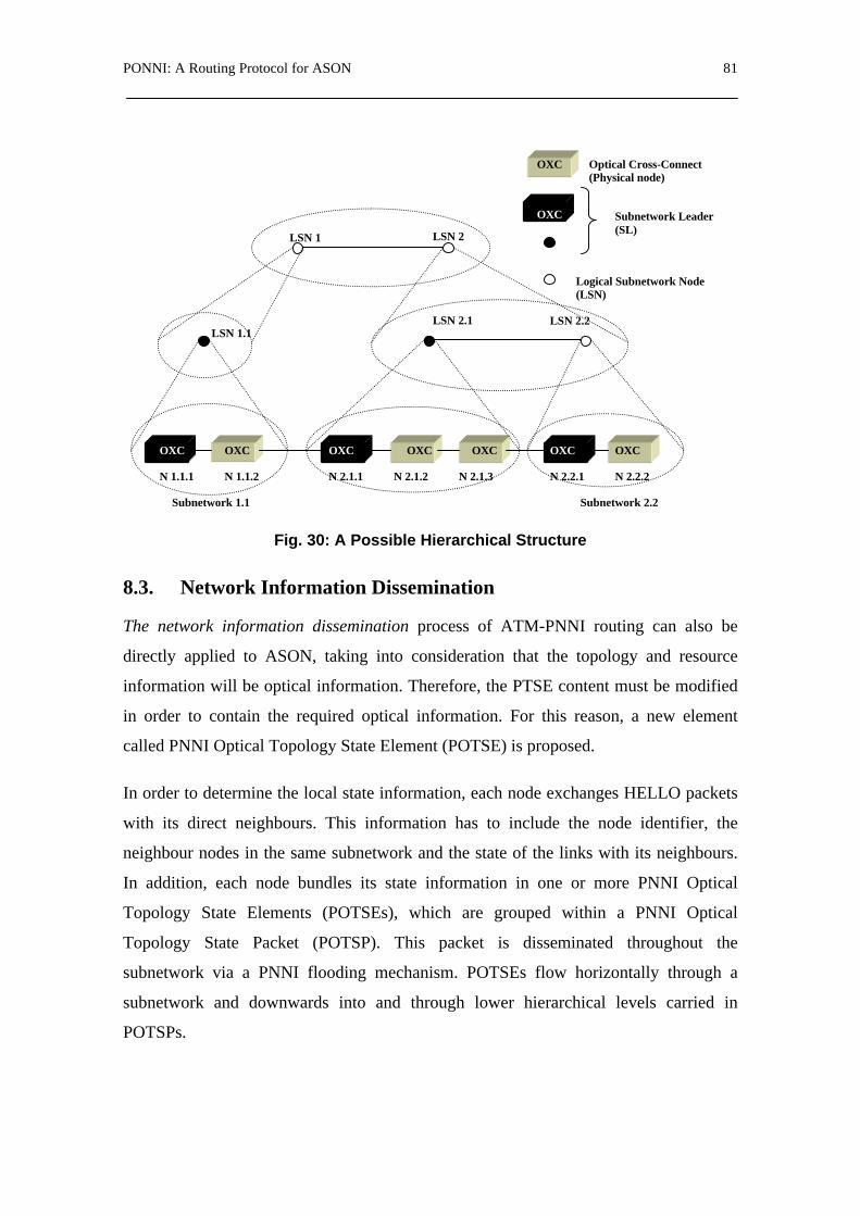
PONNI: A Routing Protocol for ASON 81
Fig. 30: A Possible Hierarchical Structure
8.3. Network Information Dissemination
The network information dissemination process of ATM-PNNI routing can also be
directly applied to ASON, taking into consideration that the topology and resource
information will be optical information. Therefore, the PTSE content must be modified
in order to contain the required optical information. For this reason, a new element
called PNNI Optical Topology State Element (POTSE) is proposed.
In order to determine the local state information, each node exchanges HELLO packets
with its direct neighbours. This information has to include the node identifier, the
neighbour nodes in the same subnetwork and the state of the links with its neighbours.
In addition, each node bundles its state information in one or more PNNI Optical
Topology State Elements (POTSEs), which are grouped within a PNNI Optical
Topology State Packet (POTSP). This packet is disseminated throughout the
subnetwork via a PNNI flooding mechanism. POTSEs flow horizontally through a
subnetwork and downwards into and through lower hierarchical levels carried in
POTSPs.
OXC OXC OXC OXC OXC OXC OXC
N 1.1.1 N 1.1.2 N 2.1.1 N 2.1.2 N 2.1.3 N 2.2.1 N 2.2.2
Subnetwork 1.1 Subnetwork 2.2
LSN 1.1 LSN 2.1 LSN 2.2
LSN 1 LSN 2
OXC Subnetwork Leader (SL)
Logical Subnetwork Node (LSN)
OXC Optical Cross-Connect (Physical node)
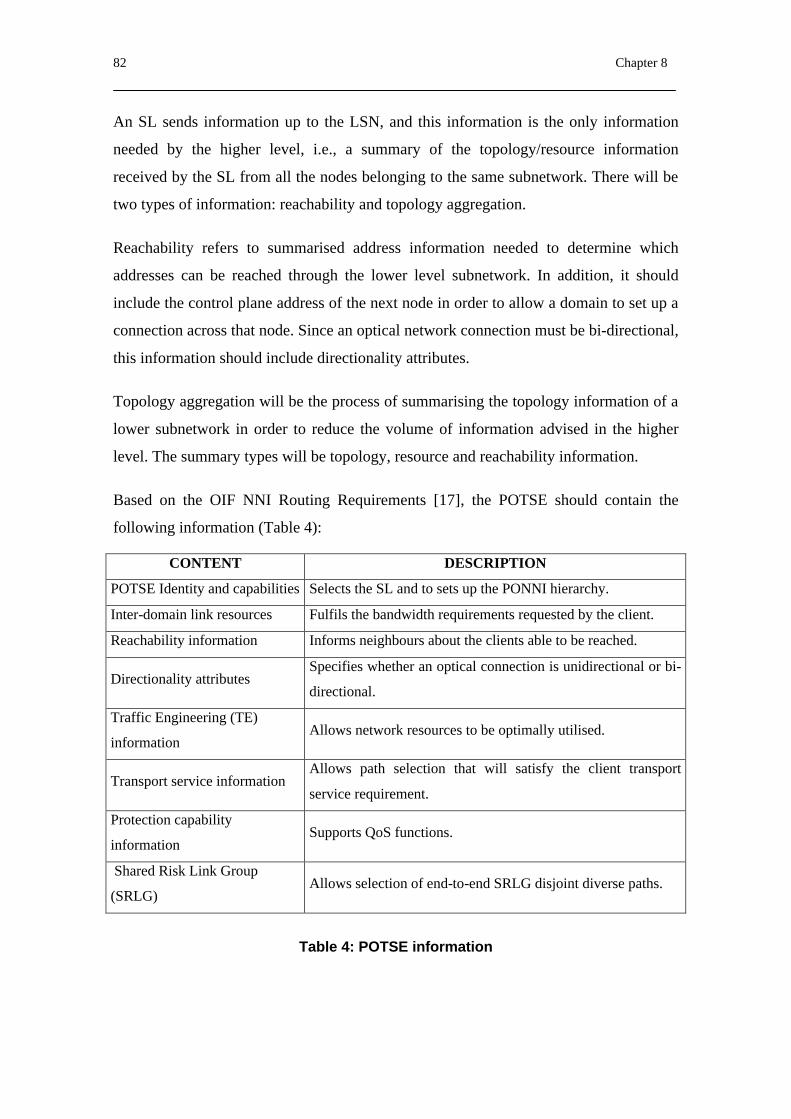
82 Chapter 8
An SL sends information up to the LSN, and this information is the only information
needed by the higher level, i.e., a summary of the topology/resource information
received by the SL from all the nodes belonging to the same subnetwork. There will be
two types of information: reachability and topology aggregation.
Reachability refers to summarised address information needed to determine which
addresses can be reached through the lower level subnetwork. In addition, it should
include the control plane address of the next node in order to allow a domain to set up a
connection across that node. Since an optical network connection must be bi-directional,
this information should include directionality attributes.
Topology aggregation will be the process of summarising the topology information of a
lower subnetwork in order to reduce the volume of information advised in the higher
level. The summary types will be topology, resource and reachability information.
Based on the OIF NNI Routing Requirements [17], the POTSE should contain the
following information (Table 4):
CONTENT DESCRIPTION
POTSE Identity and capabilities Selects the SL and to sets up the PONNI hierarchy.
Inter-domain link resources Fulfils the bandwidth requirements requested by the client.
Reachability information Informs neighbours about the clients able to be reached.
Directionality attributes Specifies whether an optical connection is unidirectional or bi-
directional.
Traffic Engineering (TE)
information Allows network resources to be optimally utilised.
Transport service information Allows path selection that will satisfy the client transport
service requirement.
Protection capability
information Supports QoS functions.
Shared Risk Link Group
(SRLG) Allows selection of end-to-end SRLG disjoint diverse paths.
Table 4: POTSE information

PONNI: A Routing Protocol for ASON 83
8.4. Hierarchical QoS Routing in Automatic Switched Optical Networks (ASONs)
The routing function can be built-in to the OXC or it can reside in a separate piece of
equipment. The optical control plane is responsible for the routing functions such as
topology discovery, dissemination of available resources and topology information, and
path selection. It is also responsible for optimising network performance, which can be
carried out via Traffic Engineering with QoS support, management of optical resources
(i.e. wavelength assignment in co-ordination with the optical channel sublayer) and
restoration. Each OXC is capable of switching a data stream from a given input port to a
given output port by appropriately configuring an internal crossconnect table. A
lightpath is established by setting up suitable crossconnects in the ingress, egress and a
set of intermediate OXCs such that a continuous physical path exists across the optical
network.
PONNI adopts a source-based hierarchical routing for supporting scalability as well as
security in a large network. The main advantage of the hierarchical routing is to reduce
large communication overhead while providing efficient routing. The source-based
hierarchical routing problem can be decomposed into two issues: how to aggregate
routing information and how to perform hierarchical routing.
There are many possible aggregation schemes. One possible adopted in [1] consists of a
complex node representation, which represents the internal structure of each Peer Group
as a symmetric star topology with a uniform radius. The virtual centre of the star is the
interior reference point of the logical node, and is referred to as the nucleus. The logical
connectivity between the nucleus and each of the domain border nodes is referred to as
a spoke. The concatenation of two spokes represents traversal of a symmetric peer
group. Moreover, for each nodal state parameter, the “diameter” of a logical node is
defined as an aggregation of all parameter values in a full-mesh representation of the
logical node. Each “diameter” must be converted to a “radius” for the default node
representation in the PNNI complex node representation. The symmetric star topology
is used as the default node representation, which consists of a single value for each
nodal state parameter giving a presumed value between any entry or exit o the logical
node and the nucleus, in either direction. Other possible aggregation schemes might
84 Chapter 8
involve advertising a minimum spanning tree of the introduced topology on the domain
border nodes. B. Awerbuch et Al. compared the performance of the different
aggregation schemes [38], include a star with radius equal to half the cost of the
network diameter (DIA), a star radius equal to half the average cost between nodes
(AVE), minimum spanning Tree (MST), Random Spanning Tree (RST) and t-spanner.
Other aggregation schemes, namely full mesh Aggregation scheme and Asymmetric
Simple Aggregation scheme are presented in [39]. They are based on the aggressive
mode defined in [1], which chooses the best value of each QoS parameter for every
intra-group links. The QoS parameters considered by these schemes are delay, capacity
and cost. However, the QoS parameters are different in optical networks and ATM
networks. Therefore, the parameters considered for optical networks are the capacity of
each wavelength on a fibre (bits/s), the propagation delay that is proportional to the
fibre distance between two nodes and the number of wavelength per link.
The performance of hierarchical routing depends on the accuracy of aggregate
information. Hence, update policy is an important issue of hierarchical routing. The
update policy is based on either a periodical refresh, or a certain threshold value, which
define when an updating message must be flooded throughout the network. Moreover,
to reduce the effects of selecting lightpaths under inaccurate network state information a
routing mechanism is needed.
8.4.1. Aggregation Schemes for PONNI
Consider a network consisting of N OXCs. Each node is assumed to have a fixed
number of ports. According to the hierarchical structure proposed above, an optical
network is divided in M subnetworks, each one composed of a set of OXCs that have
similar characteristics, existing a subset of OXCs (border OXCs) that are connected to
other subnetworks.
Let G(N,L) describe the given physical network, where N is a set of OXCs and L is a set
of links (i.e. fibres) connecting the nodes. Let g(n,l) describe the given physical
subnetwork, where n is the set of nodes (OXCs) in the subnetwork and l is a set of link
connecting the nodes within the subnetwork. Therefore, g? G, n? N and l? L.
PONNI: A Routing Protocol for ASON 85
Each fibre (link) supports k different wavelengths (colours), i.e. from λ1 to λk.
Firstly, a subnetwork pre-computes all the lightpaths existing between all border nodes
along with the QoS parameters allocated to each lightpath. Secondly, an aggregation
scheme summarizes this information reducing the amount of data to be flooded
throughout the physical network. Finally, the aggregate information from each
subnetwork is grouped in a topology database, which will be used by a source node to
compute an end-to-end lightpath.
Consider the following QoS parameters:
- C: Capacity of each wavelength on a fibre (bits/s)
- D: Propagation delay in a link which is proportional to the fibre distance
between two nodes.
- Wk: Number of available wavelength of each colour in a link
- ε: Number of wavelengths that there are in a link.
Moreover, we consider that wavelength conversion does not exist in any OXC. Thus, an
incoming call is associated to a unique wavelength colour along the lightpath.
According to aggregation schemes presented above and the QoS parameters considered
for optical network, we propose two aggregation schemes for an ASON with an PONNI
control plane, namely Lightpath Aggregation Scheme (LAS) and Node Aggregation
Scheme (NAS). These schemes include two QoS parameters, the propagation delay and
the number of available wavelengths.
8.4.1.1. Lightpath Aggregation Scheme
Lightpath Aggregation Scheme (LAS) consists in pre-computing all possible lightpaths
existing between two border nodes in the same subnetwork. According to the aggressive
mode, LAS chooses the best value of each QoS parameter and associates them to a pair
border node. The process for each parameter is as follows:

86 Chapter 8
- Aggregated Delay (Dij):
1. Compute all the lightpaths from node i to node j.
2. Add the propagation delay of each link for each ligthpath.
3. Select the minimum value among the values computed in the step 2.
- Aggregated number of available wavelength ( ijkW ):
1. Compute all the lightpaths from node i to node j.
2. Select the minimum number of wavelength per colour that is available in each path.
3. Select the maximum value among the values computed in the step 2.
Formally, the aggregated delay and available wavelength are defined as follows:
Where,
- Rij is a ligthpath between border node i and j.
- l is a link between two nodes belonging to Rij.
- k is the number of colours per fibre.
8.4.1.2. Node Aggregation Scheme (NAS)
Node Aggregation Scheme associates the aggregated QoS parameters to each border
node. The process is as follows:
= ∑
∈∀
ijij Rl
Rij lDD )(min (14)
[ ]
=
∈∀=)(minmax
..1lWW cRlRkc
ijc
ijij
(15)

PONNI: A Routing Protocol for ASON 87
- Aggregated Delay (Di):
1. Compute all the lightpaths from node i to all border nodes.
2. Add the propagation delay of each link for each ligthpath.
3. Select the minimum value among the values computed in the step 2.
- Aggregated number of available wavelength ( ikW ):
1. Compute all the lightpaths from node i to all border nodes.
2. Select the minimum number of wavelength per colour that is available on each path.
3. Select the maximum value among the values computed in the step 2.
Formally, the aggregated delay and available wavelength are defined as follows:
Where,
- Rij is a ligthpath between border node i and j.
- l is a link between two nodes belonging to Rij.
- k is the number of colours per fibre.
The choice between one of two schemes depends on two factors: the accurate
information and the signalling overhead due to flooding process of the routing
information throughout the optical network. While LAS provides better accuracy than
NAS, NAS produces less signalling overhead than LAS.
= ∑
∈≠∀
ijij Rl
ijRi lDD )(min,
(16)
[ ]
=
∈≠∀=)(minmax
,..1lWW cRlijRkc
ic
ijij
(17)

88 Chapter 8
8.4.2. Update Policy for PONNI
The time-based update policy is not adequate to cope with dynamic network traffic.
Moreover, the accuracy of aggregated information is dependent on the update interval.
If the update is set shorter, the aggregate information is more accurate. However, the
overhead of re-aggregation and information distribution becomes higher.
In [28] we proposed a new triggering policy based on a threshold value, which includes
the network resources in the triggering decision. In this way, a network node triggers an
update message when a fixed number N of wavelengths change their status, i.e. after a
fixed number of N connections are established or released. The analysis of the update
policy behaviour is out of the scope of this thesis.
8.4.3. Routing Algorithm for PONNI
PNNI does not specify a routing algorithm in order to compute routing paths. However,
it defines a set of features that have to be supported by any routing algorithm running
over the PNNI network.
In the scope of a PONNI path, computation will be performed starting from the source
routing concept, in which the Routing Component (RC) in the subnetwork ingress node
computes the end-to-end route. The selected path will be based on either a “strict
explicit route” or a “loose explicit route”:
- According to the strict explicit route paradigm, when the path is computed at the
ingress node subnetwork the ingress node has the complete topology
information. As a result, the computed route contains all the path details.
- In the loose explicit route case, the ingress node has abstract network topology
information with a summary of resource information. The computed route is a
hierarchical route and is encoded in a Designed Transit List (DTL). The path
contains all topology details about the ingress node subnetwork, but it will
contain a sequence of logical subnetwork nodes as a topology abstraction of the
rest of the network.
Therefore, the computation algorithm has to support the following functions:
PONNI: A Routing Protocol for ASON 89
- Diverse path computation including link disjoint, node disjoint and SRLG
disjoint paths for the calculation of backup paths.
- Inclusion of a hop list (DTL) in path computation.
- Optimised path computation based on TE metrics.
- Connection properties requested by the client, which include bandwidth
constraints.
Bearing in mind the above features and functions, we proposed in [28] a new routing
mechanism named “BYPASS Based Optical Routing (BBOR)”. This mechanism
reduces the effects of selecting lightpaths under inaccurate network state information. It
should be adapted to the hierarchical QoS routing. This aspect is considered as a future
work.
Closely related to the path computation and routing functions are the traffic/QoS control
features of PNNI. PNNI provides the information (through PTSE elements) necessary to
allow switching nodes to perform Connection Admission Control (CAC). Moreover,
PNNI supports a generic connection admission control (CAC) function, which indicates
whether a PNNI node can admit a new connection. PONNI incorporates similar
CAC/QoS control functionality. In PONNI, a CAC indication can be based on the
node’s topology database as well as on the connection’s attributes, such as its service
category, traffic characteristics, and QoS requirements. Having computed a path based
on the above-mentioned POTSE information and computation algorithms, each network
node along the chosen path performs the CAC function. The ability of each node to
correctly perform CAC hinges on the availability of up-to-date link/path state
information. After an ASON node accepts a connection its resource availability may
change significantly. In such cases a new POTSE instance describing the updated
resource availability of the node is produced and advertised accordingly.
On top of a CAC procedure supported by an ASON node, PONNI can also include a
generic CAC (GCAC) in the scope of the path selection process. A GCAC is used to
provide an almost safe prediction about a link or node resource availability regarding a
particular lightpath. Based on this prediction PONNI should include (or exclude) a link
90 Chapter 8
or node as a candidate path if the ASON node is likely to accept the proposed
connection (or not). Practically, a GCAC attempts to predict the result of the actual
CAC performed at an ASON node. Hence, GCAC constitutes a useful tool towards
efficiency in path computation and routing, through minimizing crankbacks. Supporting
the GCAC function in the scope of PONNI requires each node to advertise a set of
topology state parameters carrying information required by the generic CAC.
PONNI’s inherent and mature support for CAC, as well as the ability to support a
GCAC function, constitutes one of its clear advantages over GMPLS.
8.4.4. Example of Aggregation
Fig. 31 shows the perspective that the nodes belonging to the subnetwork X1 have of
the network. Each node has a topology databases containing both complete topology
information of the subnetwork X1 and information summary of the rest of the network
(Table 5). This is represented by three different types of links, which are grouped on
either physical or logical links. For example, physical link X11-X12 stands for available
resources in the link connecting nodes X11 and X12. The physical link X14-X2 stands
for the available resources in the link connecting subnetwork X1 to subnetwork X2
through node X14. Finally, logical link X1-X2 stands for the aggregated information of
subnetwork X2 from the node directly connected to subnetwork X1, i.e., X21. This
aggregated information of the logical link X1-X2 has been obtained according to the
information of the topology and available resources database shown in

PONNI: A Routing Protocol for ASON 91
Table 6 and an aggregation process applied to that database, which is described as
follows.
Fig. 31. Hierarchical QoS Routing
Table 5: Topology/available resource database in X1
Firstly, the Node Aggregation Scheme (NAS) summarizes the information of the
1
6
7
3
2 5
8
4
2 1
4
3
2
3
1
1 2
3
4 3
2 1
3
4
2 1
X1
X3
X2
Y1
Y3
Y2
X
Y
X1
X3
X2
Y1
Y3
X
Y
S
D
Link λ1 λ2 λ3 λ4 D
X11-X12 6 3 3 6 1
X12-X13 2 3 6 0 1
X13-X14 6 3 0 2 1
X12-X15 6 2 0 1 1
X15-X13 6 6 6 6 1
X15-X16 0 7 3 3 1
X16-X14 1 1 1 1 1
X11-X17 6 3 1 6 1
Link λ1 λ2 λ3 λ4 D
X17-X18 0 3 6 1 1
X18-X14 6 6 0 6 1
X14-X2 6 7 7 5 1
X18-X3 5 6 7 5 1
X1-X2 2 3 4 7 1
X1-X3 1 2 3 5 1
X3-X2 4 4 5 7 3
X-Y 4 3 2 3 5
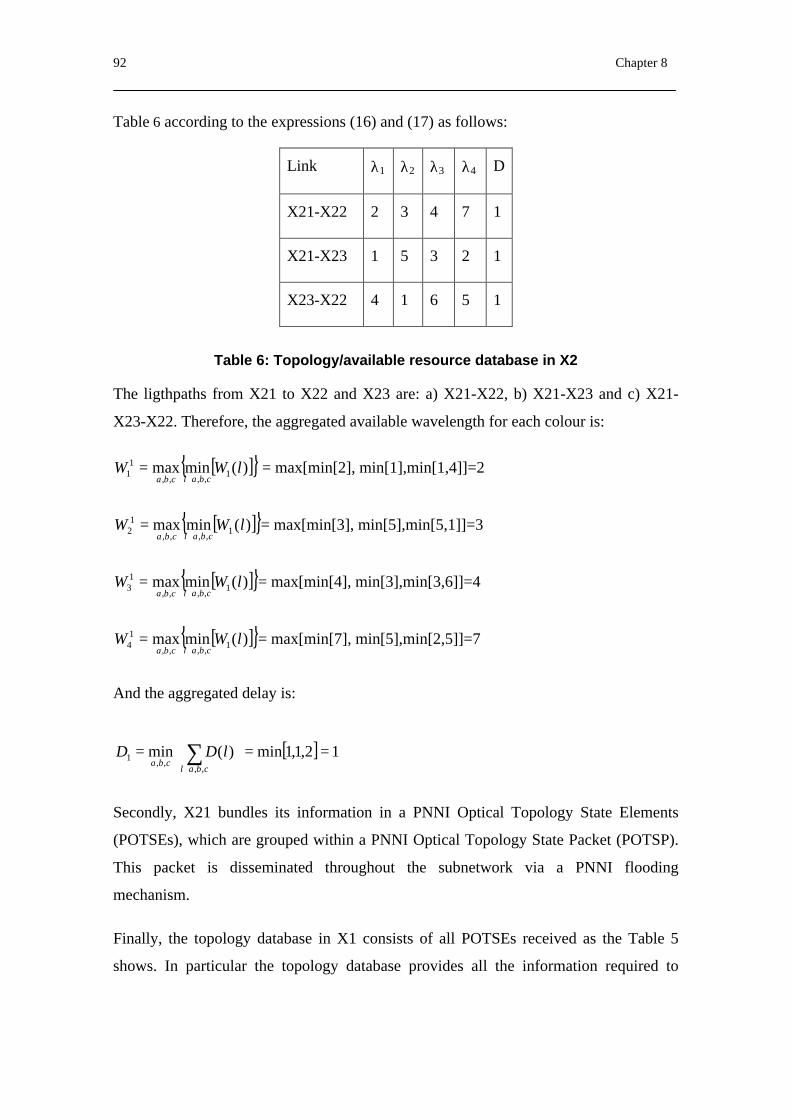
92 Chapter 8
Table 6 according to the expressions (16) and (17) as follows:
Link λ1 λ2 λ3 λ4 D
X21-X22 2 3 4 7 1
X21-X23 1 5 3 2 1
X23-X22 4 1 6 5 1
Table 6: Topology/available resource database in X2
The ligthpaths from X21 to X22 and X23 are: a) X21-X22, b) X21-X23 and c) X21-
X23-X22. Therefore, the aggregated available wavelength for each colour is:
[ ]{ })(minmax 1,,,,
11 lWW
cbalcba ∈= = max[min[2], min[1],min[1,4]]=2
[ ]{ })(minmax 1,,,,
12 lWW
cbalcba ∈= = max[min[3], min[5],min[5,1]]=3
[ ]{ })(minmax 1,,,,
13 lWW
cbalcba ∈= = max[min[4], min[3],min[3,6]]=4
[ ]{ })(minmax 1,,,,
14 lWW
cbalcba ∈= = max[min[7], min[5],min[2,5]]=7
And the aggregated delay is:
[ ] 12,1,1min)(min,,
,,1 ==
= ∑
∈ cbalcba
lDD
Secondly, X21 bundles its information in a PNNI Optical Topology State Elements
(POTSEs), which are grouped within a PNNI Optical Topology State Packet (POTSP).
This packet is disseminated throughout the subnetwork via a PNNI flooding
mechanism.
Finally, the topology database in X1 consists of all POTSEs received as the Table 5
shows. In particular the topology database provides all the information required to
PONNI: A Routing Protocol for ASON 93
compute a route from the given node any node to reachable in or through that routing
domain.
8.5. Distribution of Non-optical Information across the ASON
We define PNNI Optical Augmented Routing (POAR) as an adaptation of PNNI
Augmented Routing [4][19]. Thus, POAR will also be an extension to PONNI routing,
allowing information defined about Non-ASON services to be distributed in an ASON.
POAR will use a specific POTSE type to carry this non ASON-related information. The
Information Groups (IGs) used in ATM PAR for the flooding of IPv4-related protocol
information, such as OSPF or BGP, could be used in POAR as well. Moreover, we
propose including a new set of IGs in the POTSEs, which consists of a PAR MPLS
Services Definition IG, a PAR SDH Services Definition IG and a PAR ATM Services
Definition IG. These IGs are to allow non-IP clients such as MPLS, SDH and ATM to
be able to distribute their topology and available resource information through the
ASON.
Proxy POAR. In the specific context of IP over ASON, client network nodes have to
discover and register the different services offered by all the devices interconnected
through the ASON. In order to achieve this, a proxy POAR has to be defined. Our
definition of proxy POAR will be based on ATM proxy PAR. According to this, the
Proxy POAR would work in client mode on the current IP routers and would interact
with the Optical Cross-Connect (OXC), which would have the Proxy POAR server
installed. One of the main advantages is that due to its simplicity in client
implementation, it can be immediately incorporated into the existing devices (e.g. IP
routers, Label Switching Routers, etc.). The main purpose of Proxy POAR is to allow
Non-ASON devices to use the flooding mechanisms provided by PONNI to discover
and register the different services offered by all the devices interconnected through an
ASON.
Consider the scenario depicted in Fig. 32, in which two IP/MPLS networks are
connected through an optical backbone. The mechanism used to transport MPLS
information from one MPLS network (Domain 1) to the other MPLS network (Domain
2) through an ASON backbone (Optical Backbone) is as follows:
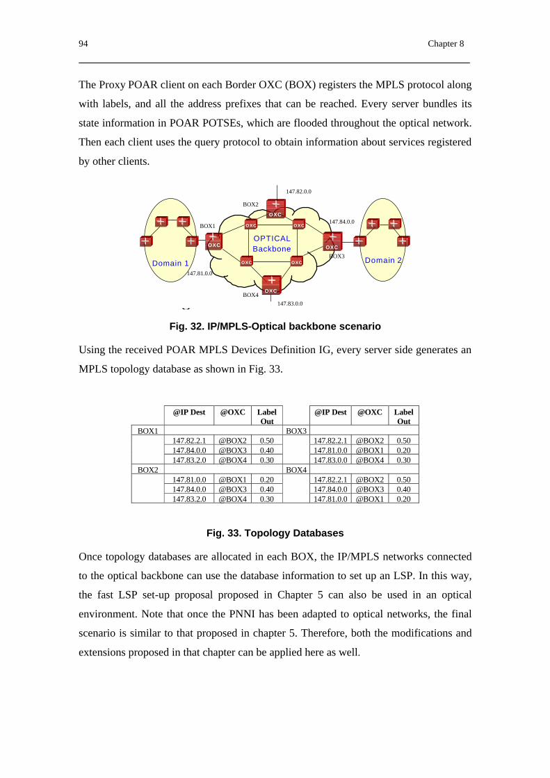
94 Chapter 8
The Proxy POAR client on each Border OXC (BOX) registers the MPLS protocol along
with labels, and all the address prefixes that can be reached. Every server bundles its
state information in POAR POTSEs, which are flooded throughout the optical network.
Then each client uses the query protocol to obtain information about services registered
by other clients.
Domain 1 Domain 2
OPTICALBackboneOXC
OXC
OXC
OXC
OXC
OXC
OXC
OXC
BOX1
BOX2
BOX3
BOX4147.83.0.0
147.81.0.0
147.82.0.0
147.84.0.0
Fig. 32. IP/MPLS-Optical backbone scenario
Using the received POAR MPLS Devices Definition IG, every server side generates an
MPLS topology database as shown in Fig. 33.
@IP Dest @OXC LabelOut
@IP Dest @OXC LabelOut
BOX1 BOX3147.82.2.1 @BOX2 0.50 147.82.2.1 @BOX2 0.50147.84.0.0 @BOX3 0.40 147.81.0.0 @BOX1 0.20147.83.2.0 @BOX4 0.30 147.83.0.0 @BOX4 0.30
BOX2 BOX4147.81.0.0 @BOX1 0.20 147.82.2.1 @BOX2 0.50147.84.0.0 @BOX3 0.40 147.84.0.0 @BOX3 0.40147.83.2.0 @BOX4 0.30 147.81.0.0 @BOX1 0.20
Fig. 33. Topology Databases
Once topology databases are allocated in each BOX, the IP/MPLS networks connected
to the optical backbone can use the database information to set up an LSP. In this way,
the fast LSP set-up proposal proposed in Chapter 5 can also be used in an optical
environment. Note that once the PNNI has been adapted to optical networks, the final
scenario is similar to that proposed in chapter 5. Therefore, both the modifications and
extensions proposed in that chapter can be applied here as well.
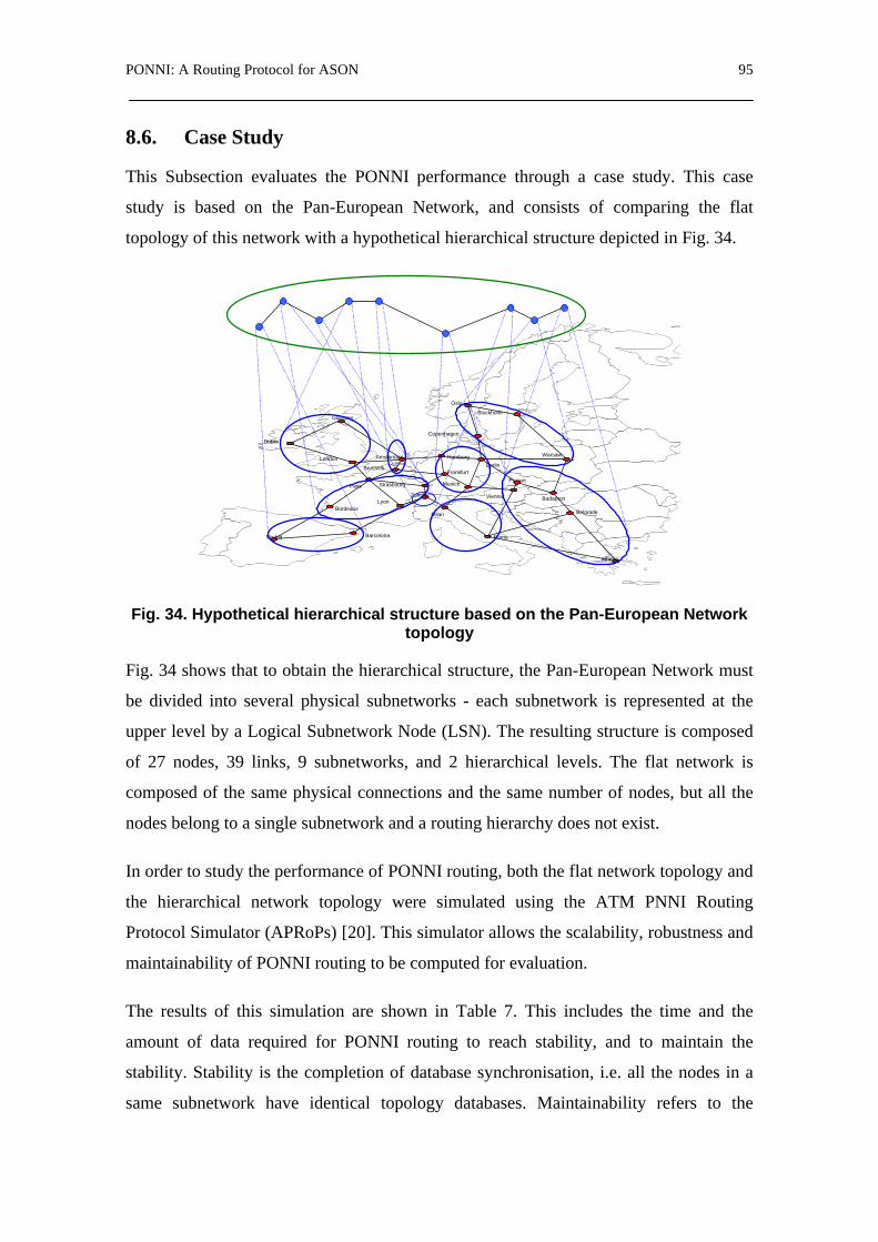
PONNI: A Routing Protocol for ASON 95
8.6. Case Study
This Subsection evaluates the PONNI performance through a case study. This case
study is based on the Pan-European Network, and consists of comparing the flat
topology of this network with a hypothetical hierarchical structure depicted in Fig. 34.
Oslo
Stockholm
Copenhagen
Amsterdam
Dublin
London
Brussels
Paris
Madrid
Zurich
Milan
Berlin
Athens
BudapestVienna
Prague
Warsaw
Munich
Rome
Hamburg
Barcelona
BordeauxLyon
Frankfurt
Glasgow
Belgrade
Strasbourg
Fig. 34. Hypothetical hierarchical structure based on the Pan-European Network topology
Fig. 34 shows that to obtain the hierarchical structure, the Pan-European Network must
be divided into several physical subnetworks - each subnetwork is represented at the
upper level by a Logical Subnetwork Node (LSN). The resulting structure is composed
of 27 nodes, 39 links, 9 subnetworks, and 2 hierarchical levels. The flat network is
composed of the same physical connections and the same number of nodes, but all the
nodes belong to a single subnetwork and a routing hierarchy does not exist.
In order to study the performance of PONNI routing, both the flat network topology and
the hierarchical network topology were simulated using the ATM PNNI Routing
Protocol Simulator (APRoPs) [20]. This simulator allows the scalability, robustness and
maintainability of PONNI routing to be computed for evaluation.
The results of this simulation are shown in Table 7. This includes the time and the
amount of data required for PONNI routing to reach stability, and to maintain the
stability. Stability is the completion of database synchronisation, i.e. all the nodes in a
same subnetwork have identical topology databases. Maintainability refers to the

96 Chapter 8
amount of data required to maintain the PONNI routing status after initial stability is
reached.
Database Synchronization Maintain PNNI Routing status
FLAT Hierarchy FLAT Hierarchy Time (seconds) 6,1016 4,1012 600 600 Total-Data (bytes) 1576856 105046 2080197 810158 Data (no Hello) (bytes) 1551416 75154 1551840 102820
Table 7. PONNI routing stability
Note that the difference between the flat and the hierarchical structure is about one order
of magnitude in favour of the hierarchical structure.
Furthermore, the scalability of the PONNI routing protocol, comparing a flat network to
a hierarchical network, has been simulated. In order to perform this simulation, 12
nodes were added to the initial configurations. Concerning the hierarchical structure, the
following logical configurations were considered: 1 subnetwork with 12 nodes, 2
subnetworks with 6 nodes each, 3 subnetworks with 4 nodes each and 4 subnetworks
with 3 nodes each. The results obtained with these simulations are shown in Fig. 35 and
Fig. 36.
Fig. 35. Scalability from flat network to a hierarchical network (Data)
100
150
200
250
300
350
400
450
500
0 1 2 3 4 5
Number of subnetworks
Dat
a (k
byt
e)
Hierarchical structureFlat structure
1000
2000
3000
4000
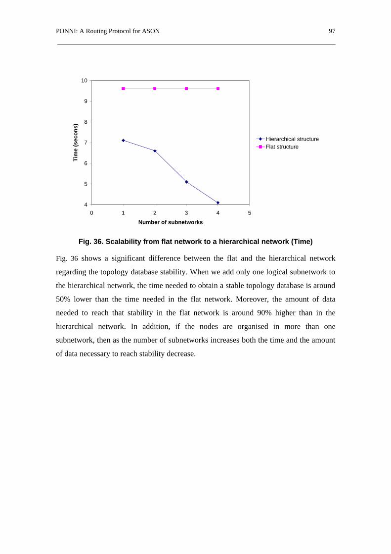
PONNI: A Routing Protocol for ASON 97
Fig. 36. Scalability from flat network to a hierarchical network (Time)
Fig. 36 shows a significant difference between the flat and the hierarchical network
regarding the topology database stability. When we add only one logical subnetwork to
the hierarchical network, the time needed to obtain a stable topology database is around
50% lower than the time needed in the flat network. Moreover, the amount of data
needed to reach that stability in the flat network is around 90% higher than in the
hierarchical network. In addition, if the nodes are organised in more than one
subnetwork, then as the number of subnetworks increases both the time and the amount
of data necessary to reach stability decrease.
4
5
6
7
8
9
10
0 1 2 3 4 5
Number of subnetworks
Tim
e (s
eco
ns)
Hierarchical structureFlat structure


Optical PNNI (O-PNNI) Control Plane 99
9. Optical PNNI (O-PNNI) Control Plane
9.1. Introduction
O-PNNI can be seen as an alternative control plane to the one provided by GMPLS
[29]. Both are based on existing protocols (PNNI and MPLS). Having an alternative to
OSPF/BGP routing and RSVP/LDP signalling is by itself a sufficient motivation for
studying and developing O-PNNI. Some issues stem from the fact that packet-switched
networks (such as MPLS-based networks) differ significantly from circuit-switched
networks (such as an ASON). Moreover, it is not clear how GMPLS based solutions
will manage QoS related issues. This is another driver in the evolution of the ATM-
PNNI, which is mature and reliable, into O-PNNI. Specifying O-PNNI hinges on
providing a routing protocol and a signalling protocol that are appropriate for ASON.
Since a major problem associated with the use of O-PNNI is that it is more difficult to
integrate with IP client networks, it is imperative that a solution for a smooth integration
with IP clients is provided.
The study of the common points between the ASON recommendations and the
respective PNNI features reveals that O-PNNI should directly inherit all these
common/similar characteristics. There are, however, several standard PNNI features
that demand adaptation before being used in the scope of ASON.

100 Chapter 9
In addition, we provide a list of possible problems that need to be addressed in the scope
of adaptations/extensions of existing PNNI protocols. Note that the list is not
necessarily complete:
- PNNI signalling is based on Q.2931, which is incompatible with RSVP-TE or
CR-LDP. However, this is not a problem for soft-permanent connections.
- PNNI signalling assumes error free operations. It is important to ensure the
required ‘bandwidth’ is available to the Service-Specific Connection-Oriented
Protocol (SSCOP) when IP or similar transport is used instead of the AAL.
Where IP transport is used, it will be important to retain the use of the SSCOP.
In this case the AAL5 has to be transported over, for example, an IP backbone.
TCP-IP could be used for this purpose or UDP-IP over point-to-point protocol
(PPP) to achieve the required quality. If the AAL is replaced by an IP
connection, the SSCOP will require the IP network to support a cell delay of
500ms (or less) and a Cell Loss Ratio of 10-6 or better.
- PNNI assumes integrated transport & control plane (no provisions for out-of-
band signalling).
Much effort is being spent on the definition of GMPLS. The ATM Forum owns PNNI
and it is unclear how extensions will be made or whether the OIF/ITU could
“commandeer” PNNI. However, in January 2002, the ATM Forum sent a Liaison to the
OIF, announcing that “the ATM Forum has agreed to begin work on defining
extensions to the PNNI signalling and routing protocols necessary for supporting optical
networks. The ATM Forum intends to base its work on the G.807, G.8080, G.7713 and
G.7715 architecture documents.”
9.2. O-PNNI Routing
The PNNI routing standard features and the ITU-T Recommendations have been
introduced in Chapter 3; In Chapter 8, an adaptation of the ATM PNNI routing protocol
has been proposed to be used in Automatic Switched Optical Networks. In particular it
has been proposed a routing protocol called PONNI, which provide the ASON with a
hierarchical QoS routing, a topology information flooding mechanism and a protocol
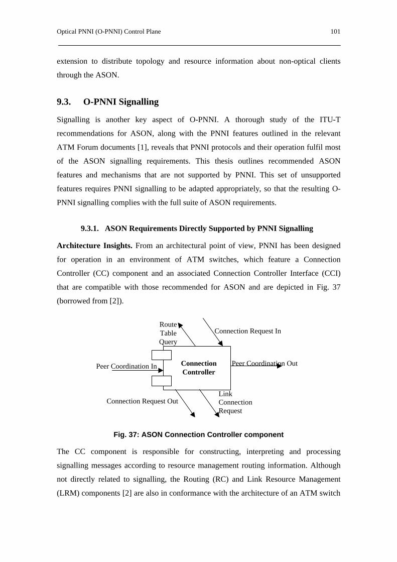
Optical PNNI (O-PNNI) Control Plane 101
extension to distribute topology and resource information about non-optical clients
through the ASON.
9.3. O-PNNI Signalling
Signalling is another key aspect of O-PNNI. A thorough study of the ITU-T
recommendations for ASON, along with the PNNI features outlined in the relevant
ATM Forum documents [1], reveals that PNNI protocols and their operation fulfil most
of the ASON signalling requirements. This thesis outlines recommended ASON
features and mechanisms that are not supported by PNNI. This set of unsupported
features requires PNNI signalling to be adapted appropriately, so that the resulting O-
PNNI signalling complies with the full suite of ASON requirements.
9.3.1. ASON Requirements Directly Supported by PNNI Signalling
Architecture Insights. From an architectural point of view, PNNI has been designed
for operation in an environment of ATM switches, which feature a Connection
Controller (CC) component and an associated Connection Controller Interface (CCI)
that are compatible with those recommended for ASON and are depicted in Fig. 37
(borrowed from [2]).
Link Connection Request
Connection Request In
Connection Request Out
Peer Coordination In Peer Coordination Out Connection Controller
Route Table Query
Fig. 37: ASON Connection Controller component
The CC component is responsible for constructing, interpreting and processing
signalling messages according to resource management routing information. Although
not directly related to signalling, the Routing (RC) and Link Resource Management
(LRM) components [2] are also in conformance with the architecture of an ATM switch
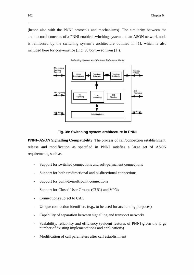
102 Chapter 9
(hence also with the PNNI protocols and mechanisms). The similarity between the
architectural concepts of a PNNI enabled switching system and an ASON network node
is reinforced by the switching system’s architecture outlined in [1], which is also
included here for convenience (Fig. 38 borrowed from [1]).
Fig. 38: Switching system architecture in PNNI
PNNI–ASON Signalling Compatibility. The process of call/connection establishment,
release and modification as specified in PNNI satisfies a large set of ASON
requirements, such as:
- Support for switched connections and soft-permanent connections
- Support for both unidirectional and bi-directional connections
- Support for point-to-multipoint connections
- Support for Closed User Groups (CUG) and VPNs
- Connections subject to CAC
- Unique connection identifiers (e.g., to be used for accounting purposes)
- Capability of separation between signalling and transport networks
- Scalability, reliability and efficiency (evident features of PNNI given the large number of existing implementations and applications)
- Modification of call parameters after call establishment

Optical PNNI (O-PNNI) Control Plane 103
- Connection routing so that a single call controller can monitor them (supported through the DTL mechanism)
- Call Release can be initiated by any call controller
- Security features at the UNI
- Support for CoS
- Protection and restoration mechanisms
- Flexible support for future extensions
- Connection establishment takes place given the addresses of the called and calling parties
- Support for crankback capabilities
- Existing calls undistorted in the case of failures in the signalling network
- On the event of signalling network failure, Call Controller and Connection Controller components can access the status of existing connections (i.e. during the restoration phase)
- ASON call and connection states are supported.
The above list is only indicative. It should be emphasized that this section is limited to
listing the set of most important ASON features that are supported by PNNI without any
essential modifications. It is out of the scope of this document to provide a complete list
of matching ASON/PNNI features; rather the focus is on features that ask for
adaptations, modifications and/or enhancements.
9.3.2. ASON Requirements Demanding PNNI Signalling Adaptation
Support out of band signalling. MPLS performs in-band signalling, using the data
channel to transport signalling messages: there is an implicit association of a control
channel to a data channel. A different case is when there is no explicit association of
control channels to data channels, as occurs in GMPLS, which supports separate control
and data planes. In this case additional signalling information is needed to identify the
particular data channel. This feature is important to support technologies in which the
control traffic cannot be sent in-band with the data traffic. GMPLS supports explicit
data channel identification by providing interface identification information. The
upstream node indicates its choice of data interfaces by using addresses and identifiers

104 Chapter 9
[22]. As with MPLS, PNNI uses in-band signalling where the signalling information is
distinguished from the data traffic by using the VPI and VCI identifiers with values 5
and 0 respectively. Because separated control and data planes for ASON are
recommended, this thesis proposes providing interface identification information to O-
PNNI signalling in order to support an association between the planes. This suggestion
is based on recommendation G.7713.1 [18], which provides the protocol specifications
for distributed call and connection management based on PNNI/Q2931. Two possible
options are considered here:
- The first option consists of adding a new information element, an Interface
Identifier, in the signalling messages. This element should include an interface
identifier and a node identifier used by the source node to identify a data
channel.
- The second option consists of using a Generic Identifier Transport Element,
which is defined in recommendation Q.2931 and explained above in Chapter
4.The interface information related to the data channel can be carried in the
Generic Identifier transport Element. Moreover, the addition of two instances, an
Interface Identifier and a Node Identifier, is also recommended. The format of
this element is shown in Fig. 39:
Fig. 39: Generic Identifier Transport Element
Signalling support for all types of transport layer networks (i.e. SDH, OTN, PDH).
PNNI is dedicated to supporting ATM connections, and deals with the manipulation of
parameters at the ATM layer. On the other hand, O-PNNI constitutes a control plane for
Information Element Identifier = Generic Identifier transportIE (0x7F)
Ext Coding standard IE Instructions field Length of contents of information element
Identifier related standard/application = (0x0K) Identifier type = Session (0x01)
Identifier length = N octets (0x0N) Node Identifier (node address)
Identifier type = Session (0x01) Identifier length = M octets (0x0M)
Interface Identifier
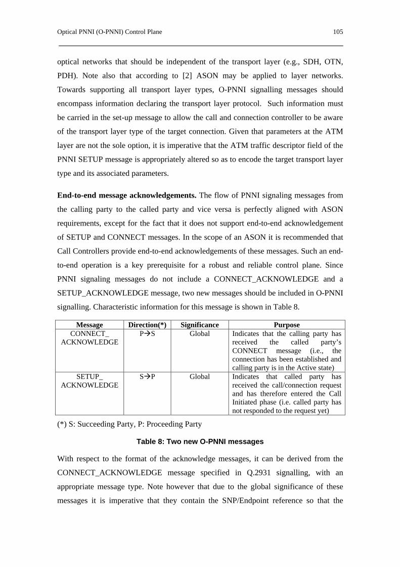
Optical PNNI (O-PNNI) Control Plane 105
optical networks that should be independent of the transport layer (e.g., SDH, OTN,
PDH). Note also that according to [2] ASON may be applied to layer networks.
Towards supporting all transport layer types, O-PNNI signalling messages should
encompass information declaring the transport layer protocol. Such information must
be carried in the set-up message to allow the call and connection controller to be aware
of the transport layer type of the target connection. Given that parameters at the ATM
layer are not the sole option, it is imperative that the ATM traffic descriptor field of the
PNNI SETUP message is appropriately altered so as to encode the target transport layer
type and its associated parameters.
End-to-end message acknowledgements. The flow of PNNI signaling messages from
the calling party to the called party and vice versa is perfectly aligned with ASON
requirements, except for the fact that it does not support end-to-end acknowledgement
of SETUP and CONNECT messages. In the scope of an ASON it is recommended that
Call Controllers provide end-to-end acknowledgements of these messages. Such an end-
to-end operation is a key prerequisite for a robust and reliable control plane. Since
PNNI signaling messages do not include a CONNECT_ACKNOWLEDGE and a
SETUP_ACKNOWLEDGE message, two new messages should be included in O-PNNI
signalling. Characteristic information for this message is shown in Table 8.
Message Direction(*) Significance Purpose CONNECT_
ACKNOWLEDGE PàS Global Indicates that the calling party has
received the called party’s CONNECT message (i.e., the connection has been established and calling party is in the Active state)
SETUP_ ACKNOWLEDGE
SàP Global Indicates that called party has received the call/connection request and has therefore entered the Call Initiated phase (i.e. called party has not responded to the request yet)
(*) S: Succeeding Party, P: Proceeding Party
Table 8: Two new O-PNNI messages
With respect to the format of the acknowledge messages, it can be derived from the
CONNECT_ACKNOWLEDGE message specified in Q.2931 signalling, with an
appropriate message type. Note however that due to the global significance of these
messages it is imperative that they contain the SNP/Endpoint reference so that the

106 Chapter 9
message can reach its final destination. Based on a 7-byte Endpoint information
element the variable part of the CONNECT_ACKNOWLEDGE message can be
specified directly.
A CONNECT_ACKNOWLEDGE message with local significance specified in the
scope of Q.2931 is also proposed to be used in the O-PNNI control plane, since hop-by-
hop acknowledgements could be extremely valuable when time critical restoration tasks
are carried out.
Alarm suppression during connection release. ITU’s recommendation for the ASON
architecture [2] proposes that ASON provide capabilities for distinguishing between
changes in the state of connections due to management or control plane actions, and
those arising from network failures. It is consequently recommended that alarms
regarding these states are appropriately generated or suppressed. GMPLS Signalling
(based on RSVP-TE) tackles with this set of requirements through appropriate handling
of Administrative Status Information [22]. Administrative status information is carried
in an appropriately defined object/TLV, and includes an indication of the administrative
status of an LSP (e.g., “up”, “down”, “testing” etc.). Furthermore, administrative status
information comprises actions that are taken by a particular network node. In the scope
of these actions GMPLS signalling (RSVP-TE & extensions) can inhibit alarm reporting
when an LSP is in the “down” or “testing” states.
On the other hand, PNNI does not include an obvious mechanism for suppressing
alarms during connection release. This proposes an enhancement of PNNI in the scope
of its evolution/transformation to O-PNNI. A possible solution is to make use of the
NOTIFY message that is currently present in PNNI signalling. NOTIFY messages are
used to convey information with respect to the call or connection. The introduction of a
new Notification Indicator Code, signifying the suppression of all alarms for a given
call/connection could allow alarm suppression to be implemented in a straightforward
manner.
Support all UNI, E-NNI and I-NNI attributes. UNI, E-NNI and I-NNI set-up
messages contain various attributes. All of these can be directly encapsulated in the
scope of the PNNI SETUP message. Nevertheless, special provisions should be made to

Optical PNNI (O-PNNI) Control Plane 107
encode appropriately the CoS/GoS fields specified in [18], and match them with the
respective parameters contained in the placeholder for QoS parameters originally
envisaged in the scope of the PNNI messages.
Adaptation of UNI, E-NNI, I-NNI signalling messages. The contents of UNI, E-NNI
and I-NNI signalling messages specified in [18] should be appropriately encapsulated in
PNNI signalling messages. Again PNNI messages provide placeholders for all attributes
of these messages, except for the CallSetupConfirm message, as the latter is specified in
all three interfaces (UNI, E-NNI, I-NNI). Following the process outlined in paragraph
4.2.2 would define SETUP_CONFIRM messages, so that O-PNNI becomes aligned to
[18].
Apart from the above adaptations and enhancements of PNNI signalling, O-PNNI must
also support all return codes and messages recommended by ITU-T for ASON (e.g., call
set-up error codes indicating error causes). Thus, PNNI needs to be enhanced to include
additional indicators in existing signalling fields.
9.3.3. Integrating Client Networks with O-PNNI Signalling
Having a core ASON at hand, one has to tackle the issue of signalling compatibility
with other client networks. When it comes to signalling compatibility a slight weakness
of O-PNNI (comparing to the GMPLS/RSVP-TE alternative) comes into the
foreground. In particular, GMPLS/RSVP-TE enables a smoother integration with client
IP/MPLS networks, which most likely run a GMPLS control plane. This is because O-
PNNI demands that RSVP enabled client networks translate their signalling messages to
PNNI messages, which is not required in the case of a GMPLS-based control plane. On
the other hand, O-PNNI ATM client networks bear an affinity to O-PNNI since they
share several signalling similarities.
In a pragmatic consideration of an ASON most client networks are assumed to be
running on IP, conveying their requirements for switched connections based on the
RSVP protocol. Signalling compatibility is strongly dependent on the routing models
and protocols. Generally, a signalled overlay model is assumed, since the O-PNNI
network is likely to be totally decoupled from the different client (sub) networks. This

108 Chapter 9
requires an overlay network internetworking model. The use of a peer-to-peer model for
internetworking between IP client networks and ASON would require a tremendous and
unjustified signalling adaptation overhead. Based on these assumptions the issues of
signalling compatibility at the ASON UNI is discussed. It should also be emphasized
that the assumptions made above are perfectly aligned to the use of RSVP-TE as a UNI
signalling protocol.
ATM Client Networks. In the case of ATM networks the compatibility between ATM
signalling and O-PNNI is quite straightforward. This is because O-PNNI signalling
messages are derived from Q.2931 signalling [3]. As a result, when an ATM signalling
message (e.g., a SETUP message) arrives at the boundary between the client network
and the ASON core, the parameters can be mapped directly to the corresponding O-
PNNI (i.e. SETUP) message. According to the overlay model, the calling and called
party information in the O-PNNI message will be determined by the source and
destination addresses of the source’s message. In particular, it is necessary to consult
routing information so that a route between the ingress and egress points of the ASON
network can be determined, along with the addresses of the ingress and egress points.
This information, along with the mapping of the UNI signalling parameters to those of
O-PNNI will then be used to construct the necessary O-PNNI signalling messages. The
ingress and egress O-PNNI nodes are expected to be capable of understanding and
parsing ATM UNI signalling messages.
It should be noted however, that in the case of ATM networks internetworking with O-
PNNI controlled ASONs, a peer-to-peer internetworking model could also be possible.
In such a case the client’s messages would flow end-to-end (almost) unchanged.
Nevertheless, such a model could hardly support IP-based clients.
MPLS/GMPLS/IP Client networks. This internetworking case is less simple and
much more interesting, since RSVP-TE messages have a totally different structure from
O-PNNI messages. In this case a special Internetworking Signalling Unit (IWU) is
required to perform the necessary mapping between the UNI and NNI signalling
protocols. From an implementation perspective this unit can either be attached (i.e.,
software modules in an attached workstation) or embedded in the border O-PNNI
capable OXC node.
Optical PNNI (O-PNNI) Control Plane 109
The IETF has conducted considerable work related to RSVP and ATM signalling
compatibility [23], [24], [25] and [26]. This work should be reused towards defining the
target signalling internetworking. The basic idea is to reuse this work to map objects in
RSVP Path/Resv messages to PNNI signalling parameters. As in the case of the ATM
client network and in line with the considered overlay model, information about the
addresses of the ingress and egress OXCs should be derived from the routing protocols.
Also, a mapping between GMPLS signaling parameters pertaining to optical networking
and the corresponding O-PNNI parameters should be defined.
[26] provides a framework for RSVP signalling over ATM. Key issues and concepts
within this IETF contribution are also applicable in the internetworking currently being
studied. An important issue regarding signalling compatibility is the management of
switched lightpaths, which is crucial given the fact that there are many options
regarding the establishment of O-PNNI lightpaths as a result of RSVP signalling
messages. One issue is related to the fact that RSVP control is receiver oriented, while
O-PNNI messages for lightpath establishment are generated at the calling/source nodes.
This mismatch is not a problem, as in RSVP-TE actual reservation of resources is also
made at the source’s side. During the process of exchanging messages between the
sender and the receiver, the ingress point of the ASON network will ultimately receive a
Resv message. At this instant, the ingress point can use O-PNNI to initiate the set-up of
an optical channel through the ASON core network.
Another issue relates to a scheme for mapping RSVP associated data flows to
lightpaths. Several schemes are possible, the simplest one routing all RSVP data flows
directed between the same (ingress, egress) pair over a single lightpath. Although this
may work well for a single CoS, it is not sufficient when it comes to managing several
CoS. In such a case, having different lightpaths per CoS for a specified source-
destination pair within the ASON is the least required. Furthermore, this issue becomes
much more complicated when it comes to supporting multicasting and reservations
featuring some degree of heterogeneity [26]. Dynamic QoS and transitions of receivers
can be efficiently supported by using the O-PNNI MODIFY family of signaling
messages in response to RSVP-TE refresh requests.

110 Chapter 9
It is noteworthy that [25] provides a rather detailed mapping of Guaranteed Service and
Controlled Load Service traffic parameters to ATM traffic descriptors. This mapping is
of limited interest for signalling internetworking, given that we are considering RSVP
and PNNI from a signalling perpective only. However, in the case where RSVP
messages convey information regarding a particular CoS, that document comes into the
foreground.
9.4. O-PNNI Addressing
Although there are potentially several ways to tackle the addressing problem it is always
preferable to use existing addressing schemes since they are robust and mature. Also, in
most cases use of existing addressing schemes facilitates the reuse of conventional
routing and signalling protocols. For instance, the GMPLS based control planes are
based on OSPF/BGP for routing and RSVP-TE/CR-LDP protocols for signalling. These
protocols are designed for use with IP-based interfaces. Thus, IP addressing comes
naturally into the foreground for use with a GMPLS framework. On the other hand, O-
PNNI protocols are based on traditional ATM/PNNI and therefore do not utilize IP
addresses. Furthermore, using conventional IP addressing in the scope of O-PNNI is not
an obvious choice given the fact that PNNI relies on NSAP addressing for identifying
nodes.
In light of these observations this contribution highlights potential solutions for the
addressing problem in optical networks that make use of O-PNNI protocols for routing
and signalling. These main options are investigated:
- Use simple, flat non-hierarchical addressing.
- Adapt the NSAP addresses so that conventional IP addressing can be used. This
allows smoother integration with client IP-based networks.
- Use ATM E.164addresses, as in original PNNI.
No matter which addressing scheme is selected for use with O-PNNI, a mechanism for
interworking with IP client networks and interpreting IP addresses within the optical

Optical PNNI (O-PNNI) Control Plane 111
core should be devised. The latter is essential to allow IP traffic to be routed over the
OTN.
Flat addressing
A simplest possible addressing scheme is that the network administrator assigns unique
addresses to all nodes. Such a scheme may be feasible in current optical networks that
have fairly few nodes. However, such a scheme would not scale well for large optical
networks. Given that future optical networks will build hierarchies, a flat scheme could
only work in the short term. Also a flat scheme does not comply with the hierarchical
routing capabilities offered in the scope of O-PNNI. Another argument against a flat
scheme is that it will be proprietary, meaning that protocols will have to be custom
designed to support new features.
IP-based addressing schemes
Another option for addressing in the scope of O-PNNI is to use conventional IP
addresses for O-PNNI node interfaces. This option is in line with the addressing
schemes used in the scope of GMPLS, and requires adapting the NSAP addresses so
that conventional IP addressing can be used. This scheme allows for the smoother
integration with client IP-based networks. IP addresses can be supported by PNNI by
setting the Address Family Identifier (AFI) to a value of 35, thus indicating that IP
addresses are used.
With this option, PNNI routing could use the IP addresses as mentioned in Section 8.2.
Thus, the first 72 bits of the IPv6 addresses (i.e. the Format prefix, Top-level
Aggregation Identifier, Reserved, Next-level Aggregation Identifier and Site-level
Aggregation Identifier fields) could be used as the subnetwork Identifier (sID). Thereby,
the sID will be a prefix of IPv6 addresses such that the organisation that administers the
subnetwork has assignment authority over that prefix. Therefore, the sID will be
encoded using 9 bytes, 1 byte (8 bits) as a level indicator followed by 8 bytes (64 bits)
of identifier information. The value of the level indicator will be between zero and 64.
The value sent in the identifier information field will be encoded with the 64-n right-
most bits set to zero, where n is the level.

112 Chapter 9
E.164 addresses
Another addressing option is to use ATM E.164 addresses, as in original PNNI
signalling. Although this option applies perfectly to the hierarchical routing mechanisms
of PNNI, it is less easy to integrate with IP client networks. In practice a small subset of
E.164 would be sufficient for supporting ASON node addressing.
9.5. O-PNNI vs. GMPLS: pros and cons
Due to exponential IP traffic growth it is commonly agreed that IP will be the dominant
client in future transport networks. Therefore, almost all suggestions on the definition of
ASON control planes were based on the IP/MPLS concepts. The GMPLS control plane
framework promises the most optimised concept for IP/OTN network migration. Only
recently, a few participants of the standardization forum have requested the
investigation and adaptation of ATM Forum’s PNNI protocol suite for ASONs - also
initially derived from IP protocol concepts and adapted for a connection-oriented
architecture.
Current IP control plane protocols lack many functions needed by an ASON control
plane. The GMPLS framework currently being developed addresses many of these
issues, but it is not clear to what extent. PNNI satisfies many needs of an ASON control
plane but would need further ASON-specific extensions, which are mentioned above.
The GMPLS control architecture describes the control plane as possibly detached and
independent of the transport plane. The PNNI control plane is merged with the transport
plane, in the sense that ATM control cells are transported across the network via the
ATM transport plane itself, although via a distinct VPI/VCI. The separation of transport
and control planes is important in optical networks, because optical control signals (or
wavelengths) need to be terminated at each network element participating in the control
plane, whereas data signals only need to be terminated at add/drop points. Basically,
out-of-band signalling is an important alternative for the transport of control
information.
In PNNI, signalling is only exchanged in-band, via a specific VPI/VCI. PNNI signalling
is based on ATM Forum UNI signalling, and additionally supports source routing,

Optical PNNI (O-PNNI) Control Plane 113
crankback, and alternate routing of call set-up requests in case of a connection set-up
failure. In GMPLS, the control message exchange can be done via in-band or out-of-
band signalling. Two signalling protocols, RSVP-TE and CR-LDP, are being
considered to establish label-switched paths within an ASON/ASTN. Paths can be
established based on various criteria, such as bandwidth requirements and protection
levels.
GMPLS uses IPv4 and/or IPv6 addresses whereas PNNI uses NSAP addresses, which
do not support IPv4 or IPv6 formats. Therefore, no common address space may be built
with IP-based networks. In an overlay model, address resolution at the UNI is needed
anyway, since the address spaces of the client and transport networks are separated.
Soft-Permanent Virtual Connections (SPVCs) are supported by PNNI and are a popular
management feature. Soft-permanent connections seem very useful for ASONs/ASTNs
as well, and would be especially helpful for the migration from non-ASON/ASTNs to
ASON/ASTN transport networks.
Dynamic routing protocols, such as Open Shortest Path First (OSPF) and Intermediate
System-to-Intermediate System (IS-IS) use a simple metric to calculate the best path
through a network. The ATM PNNI protocol also performs best path calculations, but
includes support for QoS characteristics to determine the optimal path based on a
number of additional criteria, such as bandwidth and delay. Optical networks have their
own QoS-like constraints, bandwidth being the most obvious, but they also require
additional parameters relating to such things as the characteristics of fibres, wavelength,
latency, bundling, diversity, and jitter. OSPF and IS-IS use traffic-engineering (TE)
extensions to propagate this QoS-related information. These traffic engineering-specific
parameters are stored at each network node, and a modified constrained shortest path
first (CSPF) engine is used to calculate a path through the network.
In PNNI, topology discovery is performed via the exchange of Topology State Packets
(PTSP), done at regular time intervals or triggered by significant available capacity
changes. In GMPLS, OSPF or IS-IS link state dissemination mechanisms can be used
for this purpose.
114 Chapter 9
PNNI constraint-based routing uses cost, capacity, link constraints, and/or propagation
delay constraints. PNNI supports rerouting around failed components at connection set-
up with the crankback feature. If a call fails along a particular route it is cranked back to
the originator of the top DTL, which finds another route or cranks back to the generator
of the next higher layer source route.
In PNNI, with the use of a Designated Transit List (DTL), a source route across each
level of hierarchy is specified. The entry switch of each peer group specifies a complete
route through that group. Multiple routing levels are realized by multiple DTLs
implemented as a stack. PNNI routing supports transit carrier selection. In GMPLS, an
ordered list of explicit hops is produced by a service agent, which can be an edge
network element, a Network Management System (NMS), or a network scheduling tool.
OSPF and IS-IS only support two hierarchical levels. Nevertheless, PNNI supports
multiple levels of hierarchy and therefore is scalable for global networking. It can treat a
cloud as a single logical link.
In PNNI, neighbour discovery takes place via a hello protocol. Hello packets are
exchanged at every hierarchical layer an ATM switch belongs to. This way, ATM
switches can establish whether they are border nodes with respect to a given layer or
not, and they can determine whether a link with a neighbour is a horizontal link, within
a given hierarchical layer, or an uplink. In GMPLS, adjacencies of two types can be
established: a control plane and a transport plane adjacency. Thus, two network
elements that are physically neighbours may not be neighbours as far as the control
plane is concerned.
Both PNNI and GMPLS do not support service discovery. Service discovery is a
concept introduced by the OIF, in which transport service characteristics are queried
before optical UNI signalling with the purpose of connection establishment takes place.
PNNI provides the rerouting of failed connections, if configured to do so. Domain based
rerouting of failed connections is possible. Also “protection VCs” for failure cases may
be set-up in advance. PNNI allows “slow” re-rerouting for optimisation purposes (make
Optical PNNI (O-PNNI) Control Plane 115
before break). Connection rerouting is currently at final ballot at the ATM Forum.
Failure recovery in GMPLS has recently been addressed in many IETF drafts.
In PNNI, connection admission control is part of the ATM traffic management plane. A
switch runs “generic” CAC in order to determine a source route. GCAC finds paths that
will probably support the incoming call. The “actual” CAC is run by each switch. This
CAC determines if the call can be supported. In GMPLS, connection admission control
is mentioned only in DiffServ and RSVP drafts. Thus, support for connection admission
control by GMPLS does not seem to be well developed at this moment.
Note that PNNI signalling mechanisms are radically different from GMPLS signalling,
which relies on RSVP-TE and CR-LDP, in several aspects. However, a PNNI-based
signalling solution has several advantages to offer to the control plane of optical
networks. Although RSVP-TE seems to be the preferred protocol for controlling optical
connections, it presents an important drawback: it is a “soft state“ protocol, which may
allow control plane failures to impact established optical connections. This is because
the lack of refresh messages could result in LSP deletions. Therefore, a “hard state“
protocol is certainly more appropriate for handling optical connections. Although RSVP
can be configured to be “hard state“ for use within optical networks (through very long
timeout values), O-PNNI could provide a more reliable and efficient signalling protocol
because it is “hard state“ by nature. Note also that PNNI is a circuit-based protocol that
supports explicit source routing of connections. In addition, it supports connection
rerouting and call/control separation, as well as crankback and security features. These
properties render PNNI a perfect candidate for supporting the optical control plane.
A set of PNNI modifications has been proposed to obtain the O-PNNI as an ASON
control plane. It has also been shown that both GMPLS and O-PNNI are, in principle,
well suited for ASON control planes. There are a lot of technical pros and cons for both
frameworks. They are summarised in
Table 9. It is clear that both GMPLS and O-PNNI need further extensions and
adaptations, because neither control platform supports all functions identified in this
document.

116 Chapter 9
Apart from technical features and requirements, the discussion about GMPLS and/or O-
PNNI is very much politically and market driven.
NNI Functionality O-PNNI GMPLS Comments Topology discovery & topology information distribution
Yes Yes GMPLS supports separate control and transport planes. O-PNNI achieves scalability for worldwide optical networks.
Path selection Yes Yes GMPLS: based on OSPF. O-PNNI: based on source routing.
Signalling exchange Yes Yes O-PNNI and GMPLS: in or out-of-band Signalling protocol Yes Yes GMPLS: RSVP-TE and CR-LDP. “Soft-state”
protocol. O-PNNI: based on Q.2931. “Hard-state” protocol.
Multi-layering Yes Maybe O-PNNI explicitly allows 104 levels. GMPLS may support it via nested LSPs.
Connection Admission Control
Yes No O-PNNI: GCAC and CAC.
Load balancing Yes Yes Both support traffic engineering. Service discovery No No Supported by OIF UNI 1.0 only. Addressing Yes Yes GMPLS: IPv4 and/or IPv6 addresses.
O-PNNI: NSAP addresses.
Table 9: Comparison of GMPLS and O-PNNI

117
PART IV
CONCLUSIONS AND FUTURE WORK
Chapter 10 presents a summary of this thesis and also extracts the main conclusions.
Additionally, Chapter 11 describes some lines of future research that may take this
thesis.


Summary and Conclusions 119
10. Summary and Conclusions This Thesis deals with the problem of interconnecting IP/MPLS networks through
backbones of different technologies (e.g., ATM, WDM, etc.). In this field, providing a
fast path set-up with certain QoS requirements is still an open problem, especially for
supporting real-time applications. In this Thesis, a mechanism to achieve this goal has
been proposed. The proposed mechanism allows an end-to-end path with QoS
requirements to be established between two LSRs belonging to different IP/MPLS
networks that are interconnected through a transport backbone. For the case of ATM
transport networks, the mechanism is based on the adaptation of the PNNI protocols to
transport MPLS information across the ATM backbone. The use of PNNI routing and
signalling protocols avoids both the tunnelling of the signalling messages across the
ATM backbone and the use of ATM-LSRs (i.e., ATM switches with MPLS capabilities)
in the core network. Moreover, we achieve a fast LSP establishment using a parallel
signalling process, that is, the end-to-end path is set up in all domains at the same time.
After comparing our proposal with the most relevant solutions to this problem existing
in the literature, we have seen that, besides reducing congestion in the IP/MPLS
domains, our mechanism obtains a speed-up between 6% (worst case) and 54% (best
case) relative to the existing mechanisms. Building on these results, we also use our
method to transport both the Bw and the destination IP address across the ATM
backbone in large networks. Moreover, we have proposed using a method to transport
the ATED because the LSP blocking ratio is reduced with source routing based on
accurate network state information. This method consists of an aggregation scheme that
120 Chapter 10
reduces the topology information of an IP/MPLS network to be transported across the
ATM backbone. Two different options have been proposed and analysed by simulation.
The numerical results have demonstrated that the FMA scheme provides an LSP
blocking ratio lower than the ASA scheme but the FMA produce a signalling overhead
in the ATM backbone higher than ASA scheme. Thus, we choose the FMA scheme
because the fast set-up mechanism requires a minimum blocking ratio.
In this Thesis we have also claimed that PNNI can be useful for many current and future
applications, including the Optical Transport Network control plane. Therefore, an
adaptation of the PNNI routing protocol for ASON has been proposed. It provides a
QoS hierarchical routing, a flooding mechanism and a method to distribute non-optical
information across the ASON. Extending this idea, we have elaborated on general
technical guidelines for adopting PNNI as the solution for the ASON control plane
implementation, which resulted in the definition of a preliminary O-PNNI protocol.
Some routing and signalling modifications needed to adapt PNNI to the ASON
requirements have been proposed. The feasibility of O-PNNI as the ASON control
plane has been analysed. The final conclusion is that O-PNNI, being a mature
technology, could be very practical for a seamless migration from current transport
networks to ASON. The selection of either the GMPLS or the O-PNNI approach is
influenced by several factors, not least the expected high penetration of IP and its
integration with Optics. Whether to use GMPLS or O-PNNI as an ASON/ASTN control
plane is a choice that raises a host of trade-offs to consider. The most important of these
have been highlighted in the scope of the sections of this document comparing the two
alternatives.

Future Work 121
11. Future Work This thesis has defined several guidelines for optical networks. Therefore, the future
work will be focussed on following these guidelines and finishing the O-PNNI
definition. Various significant points to complete the O-PNNI definition should be
considered.
The routing mechanism recommended in Chapter 9 should be adapted to be used as a
hierarchical QoS routing. This mechanism along with the update policy and the
aggregation scheme will be used to evaluate the hierarchical QoS routing performance
in optical networks.
Parameters advertised within the proposed PNNI Optical Topology State Element
should be exactly specified and the POTSE format has to be also dimensioned.
Chapter 9 proposes a signalling method to support out of band signalling. It defines a
new Generic Identifier Transport Element to carry both node and interface identifier.
The length of these components should be specified depending on the addressing
scheme selected.
ASON requires a service discovery procedure that PNNI does not support. It should be
provided to allow transport service characteristics to be queried before establishing a
connection.
Finally, a preliminary document with the definition of the O-PNNI control plane for
ASON should be submitted to an organization of standardization for evaluation.


123
References [1] ATM Forum, “Private Network to Network Interface Specification Version 1.1”, af-
pnni-0055.002, April 2002
[2] ITU-T Rec. G.8080/Y.1304 “ Architecture for the Automatic Switched Optical
Network (ASON)”, November 2001
[3] ITU-T Rec. Q.2931 “B-ISDN-DSS2-UNI Layer 3 Specification for Basic
Call/Connection Control”, February 1995
[4] ATM Forum, “PNNI Augmented routing (PAR)”, Version 1.0, af-ra-0104.000,
January 1999.
[5] P. Droz. and T. Przygienda, “Proxy-PAR”, IETF RFC 2843, May 2000.
[6] T. Przygienda, P. Droz and R. Haas,” OSPF over ATM and Proxy-PAR”, IETF RFC
2844, May 2000
[7] B. Davie et al., “MPLS using LDP and ATM VC Switching”, IETF RFC 3035,
January. 2001
[8] E.C. Rosen, A. Viswanathan and R. Callon, “Multiprotocol Label Switching
Architecture”, IETF RFC 3031, July 2000.
[9] K. Nagami, Y.Katsube, N. Demizu, H. Esaki and P. Doolan, “VCID Notification
over ATM link for LDP”, IETF RFC 3038, January 2001.
[10] M. Suzuki, “The Assignment of the Information Field and Protocol Identifier in
the Q.2941 Generic Identifier and Q.2957 User-to-user Signaling for the Internet
Protocol”, IETF RFC 3033, January 2001.
[11] S. Sánchez-López, X. Masip-Bruin, J. Domingo-Pascual, J. Solé-Pareta, “A
Solution for Integrating MPLS over ATM”, in Proc 15th International Symposium
on Computer and Information Sciences (ISCIS2000), Oct. 2000, pp.255-303.
[12] S. Sánchez-López, X. Masip-Bruin, J. Domingo-Pascual, J. Solé-Pareta, J.
López-Mellado, “A Path Establishment Approach in an MPLS-ATM Integrated
Environment”, IEEE GlobeCom, November 2001
[13] S. Sánchez-López, X. Masip-Bruin, J. Solé-Pareta, J. Domingo-Pascual,
“Providing QoS in an MPLS-ATM Integrated Environment”, QoFIS 2002, October
2002

124
[14] X. Masip-Bruin, S. Sánchez-López, J. Solé-Pareta J. Domingo-Pascual, “QoS
routing algorithms under inaccurate routing information for bandwidth constrained
applications”, IEEE ICC, May 2003.
[15] D. Katz, D. Yeung, K. Kopella, “Traffic Engineering Extensions to OSPF
Version 2”, draf-katz-yeung-ospf-traffic-10.txt, June 2003
[16] S. Sánchez-López, X. Masip-Bruin, J. Solé-Pareta, J. Domingo-Pascual,
“PONNI: A routing information exchange protocol for ASON”, EURESCOM
2002,October 2002
[17] Angela Chiu, et al., “NNI routing requirements”, oif2001.508, October 2001.
[18] ITU-T Rec. G.7713/Y.1704.1 “Distributed Call and Connection Management
(DCM) based on PNNI”, March 2003.
[19] R. Haas, P. Droz and D. Bauer, “PNNI Augmented Routing (PAR) and Proxy-
PAR”, Computer Networks, vol. 34 (2000), pp. 399-418.
[20] Song, Y.,“ The NIST ATM PNNI Routing Protocol Simulator (APRoPS),
Operation and Programming Guide”, version 1.0, December 1998
[21] ITU-T Rec. G.807/Y.1302 “requirements for the Automatic Switched Transport
Network (ASTN)”, July 2001
[22] P. Ashwood, et al. “Generalised MPLS – Signalling Functional Description”,
draft-ietf-mpls-generalized-signalling-09.txt, February 2003.
[23] Berger L.,“RSVP over ATM Implementation Guidelines”, RFC 2379, August
1998
[24] Berger L.,“RSVP over ATM Implementation Requirements”, RFC 2380,
[25] Garrrett M., et. al., “Interoperation of Controlled-Load Service and Guaranteed
Service with ATM“, RFC 2381, August 1998.
[26] Crawley E., et. al., “A Framework for Integrated Services and RSVP over
ATM”, RFC 2382, August 1998.
[27] A. Manzalini, J. Solé-Pareta, J. Soldatos, M. Jaeger, J. Comellas, G. Kylafas, S.
Sánchez-López, et al. “Recommendations for Network Evolution” Information
Society Technology (IST) program,”LION project”, IST-1999-11387, Deliverable
27, December 2002
[28] X.Masip-Bruin, R.Muñoz, S.Sànchez-López, J.Solé-Pareta, J.Domingo-Pascual,
G.Junyent, “An Adaptive Routing Mechanism for Reducing the Routing Inaccuracy
125
Effects in an ASON”, in Proceedings of 7th IFIP Working Conference on Optical
Network Design & Modelling, pp. 333-349, Budapest, Hungary, Feb. 2003
[29] S. Sánchez-López, J. Solé-Pareta, J. Comellas, J. Soldatos, G. Kylafas, M.
Jaeger, “PNNI Based Control Plane for Automatic Switched Optical Networks”,
Accepted for publication to IEEE Journal of Lightwave Technology, Special Issue
on Optical Networks 2003.
[30] V. Sharma, “Framework for Multi-Protocol Label Switching”, RFC 3469,
February 2003
[31] ITU-T. Rec. G.707/Y1322, “Network node interface for the SDH”.
[32] Cavendish D., et al., “New transport services of next generation SONET/SDH
systems”, IEEE Communications Magazine, vol. 40 n 5, May 2002.
[33] ITU-T Rec. G.691, “Optical interface for single channel STM-64, STM 256 and
other SDH systems with optical amplifier”
[34] R. Cole, et al., “IP over ATM: a framework document”, RFC 1932, April 1996.
[35] “Advanced MPLS Design and implementation”, ciscopress.com, 2000.
[36] .Iwata A., et al., “QoS Aggregation Algorithms in Hierarchical ATM networks”,
IEEE ICC, 1998.
[37] Ben-Jye Chang, et al., “Hierarchical QoS Routing in ATM Networks based on
MDP Cost Function”, IEEE ICON, 2000.
[38] Awerbuch B., et al., “Routing Through Network with Hierarchical Topology
Aggregation”, IEEE Symposium on Computer and Communications, 1998
[39] Ben-Jye, et al., “Dynamic Update of Aggregated Routing Information for
Hierarchical QoS Routing in ATM Network”, ICPADS 2001.
[40] R. Hiden, M. O’Dell, et al., “An IPv6 Aggregatable Global Unicast Address
Format”, RFC 2374, July 1998.
[41] G. Manimaran et. al., “A New Distributed Route Selection Approach for
Channel Establishment in Real-Time Networks”, IEEE/ACM Transactions on
networking, vol. 7, no. 5, October 1999.


127
APPENDIX: LIST OF PUBLICATIONS AND PROJECTS


129
Main publications
1) S. Sánchez-López, J. Solé-Pareta, J. Comellas, J. Soldatos, G. Kylafas, M. Jaeger, “PNNI Based Control Plane for Automatic Switched Optical Networks”, Accepted for publication to IEEE Journal of Lightwave Technology, Special Issue on Optical Networks, November 2003.
2) S. Sánchez-López, X. Masip-Bruin, J.Solé-Pareta, et al, “Control plane architectures for IP-over-WDM networks”. Contribution to Chapter 3 on “Design optimized reliable WDM networks" of COST 266 Final Report, September, 2003
3) S. Sánchez-López, J. Solé-Pareta, J. Soldatos, M. Jaeger, J. Comellas, G. Kylafas, A. Manzalini, et al. “Recommendations for Network Evolution” Information Society Technology (IST) program,”LION project”, IST-1999-11387, Deliverable 27, pag.122-146, December 2002
4) S. Sánchez-López, X. Masip-Bruin, J.Solé-Pareta, J.Domingo-Pascual, “PONNI: A Routing Information Exchange Protocol for ASON”, in Proceedings of EURESCOM Summit 2002, Heidelberg, Germany, October 2002
5) S. Sánchez-López, X. Masip-Bruin, J.Solé-Pareta, J.Domingo-Pascual, “Providing QoS in MPLS-ATM Integrated Environments”, in Proceedings of QofIS’02, Zürich, Switzerland, October 2002.
6) S. Sánchez-López, J. Solé-Pareta, “Preliminary functional description of Automatic Switched Optical Network (ASON)”, Information Society Technology (IST) program,”LION project”, IST-1999-11387, Deliverable 15, pag.41-46, December 2001
7) S. Sánchez-López, X. Masip-Bruin, J.Domingo-Pascual, J.Solé-Pareta, J.López, “A Path Establishment Approach in an MPLS-ATM Integrated Environment”, in Proceedings IEEE GLOBECOM, S.Antonio, Texas, USA, Nov. 2001.
8) S. Sánchez-López, X. Masip-Bruin, J.Domingo-Pascual, J.Solé-Pareta, “A Solution for Integrating MPLS over ATM”, in Proceedings of ISCIS XV, Istanbul, Turkey, October 2000.
9) S. Sánchez-López, X. Masip-Bruin, J.Domingo-Pascual, “Protocolo RSVP: evolución y experiencias”, Jornadas Técnicas RedIRIS 98, November 1998, Barcelona, Spain.
10) J.Solé-Pareta, D.Careglio, X.Masip-Bruin, S.Sanchez-López and S.Spadaro, “Some Open Issues in the Definition of a Control Plane for Optical Networks”, Invited paper submitted to IEEE 5th International Conference on Transparent Optical Networks, Warsaw, Poland, June 2003
11) De Maesschalck, D. Colle, B. Puype, Q. Yan, M. Pickavet, P. Demeester, S.Sánchez-López, X.Masip-Bruin, J. Solé-Pareta, et al, “Circuit/Wavelength Switching and Routing”, in Proceedings of 7th. International Conference on Telecommunications, ConTEL 2003, Zagreb, Croatia, June, 2003
12) J. Soldatos, G. Pikramenos, G. E. Kylafas, B. Lianos, S. Sánchez-López, J. Solé-Pareta, “Implementation PNNI Signalling in the Optical Control Plane”, Accepted for publication to WSEAS Transactions, August 2003.
13) X. Masip-Bruin, S. Sánchez-López, J. Solé-Pareta, J. Domingo-Pascual, “Hierarchical Routing with QoS Constraints in Optical Transport Networks” submitted to INFOCOM 2003.
130
Other publications 14) X.Masip-Bruin, S.Sànchez-López, J.Solé-Pareta, J.Domingo-Pascual, “An
Alternative Path Fast Rerouting in MPLS”, in Proceedings of ISCIS XV, pp.304-313, Istambul, Turkey, October 2000.
15) X.Masip-Bruin, R.Muñoz, S.Sànchez-López, J.Solé-Pareta, J.Domingo-Pascual, G.Junyent, “Mecanismo de Encaminamiento Dinámico en Redes ASON”, XII Jornadas Telecom I+D, Barcelona, Spain, November 2002.
16) X.Masip-Bruin, R.Muñoz, S.Sànchez-López, J.Solé-Pareta, J.Domingo-Pascual, G.Junyent, “An Adaptive Routing Mechanism for Reducing the Routing Inaccuracy Effects in an ASON”, in Proceedings of 7th IFIP Working Conference on Optical Network Design & Modelling, pp. 333-349, Budapest, Hungary, Feb. 2003.
17) X.Masip-Bruin, S.Sànchez-López, J.Solé-Pareta, J.Domingo-Pascual,, “A QoS Routing Mechanism for Reducing the Routing Inaccuracy Effects”, in Proceedings of 2nd International Workshop on QoS in Multiservice IP Networks, QoS-IP, pp.90-102, Milan, Italy, February 2003.
18) X.Masip-Bruin, S.Sànchez-López, J.Solé-Pareta, J.Domingo-Pascual,, “QoS Routing Algorithms Under Inaccurate Routing Information for Bandwidth Constrained Applications”, in Proceedings of IEEE International Communications Conference, ICC 2003, Anchorage, Alaska, May 2003.
19) X.Masip-Bruin, S.Sànchez-López, J.Solé-Pareta, et al. Contribution to Chapter 2 on “QoS Routing Algorithms” of COST 263 book, September, 2003
20) X.Masip-Bruin, S.Sànchez-López, J.Solé-Pareta, et al. Contribution to Chapter 3 on “Design optimized reliable WDM networks" of COST 266 Final Report, September, 2003.
21) X.Masip-Bruin, S.Sànchez-López, J.Solé-Pareta, J.Domingo-Pascual, Didier Colle, “Routing and Wavelength Assignment under Inaccurate Routing Information in Networks with Sparse and Limited Wavelength Conversions”, IEEE GLOBECOM 2003
Projects
This thesis has been developed under the support of the CICyT (Spanish Ministry of
Education) under contracts TIC99-0572-C02-02 and TEL99-1117-C03-3, the MCyT
(Spanish Ministry of Science and Technology) under contracts FEDER-TIC2002-
04531-C04-02 and FEDER-TIC2002-04344-C02-02, and the CIRIT (Catalan Research
Council) under contracts 1999-SGR00126 and 2001-SGR00226; and the Information
Society Technology (IST) program, ”Layers Internetworking in Optical Networks
(LION) project”, IST-1999-11387


