

© 2011 Cisco and/or its affiliates. All rights reserved. Cisco PublicBRKMPL-1101 1
Hari Rakotoranto
Introduction to MPLSBRKMPL-1101
NSSTG MPLS Product Manager
© 2011 Cisco and/or its affiliates. All rights reserved. Cisco PublicBRKMPL-1101 2
Goals of this Session
Understand history and business drivers for MPLS
Learn about MPLS customer and market segments
Understand the problems MPLS is addressing
Understand benefits of deploying MPLS
Understand the major MPLS technology components
Learn the basics of MPLS technology
Understand typical applications of MPLS

© 2011 Cisco and/or its affiliates. All rights reserved. Cisco PublicBRKMPL-1101 3
The Big Picture
MPLS in Core Network
Edge
Edge
Edge
Edge
Core
Core
Core
Core
Edge
Edge Edge
Edge
Network Infrastructure
MPLS Signaling and Forwarding
MPLS Signaling and Forwarding
MPLS Network Services
MPLS QoS MPLS OAM/MIBsMPLS TE
End-to-end MPLS VPN Services
End-to-end MPLS-enabled
Services
Layer-3 VPNs Layer-2 VPNs
Network Infrastructure
MPLS Signaling and Forwarding
Layer-3 VPNs Layer-2 VPNs
MPLS QoS MPLS OAM/MIBsMPLS TE
End-to-end Services
MPLS Network Services
Core MPLS
© 2011 Cisco and/or its affiliates. All rights reserved. Cisco PublicBRKMPL-1101 4
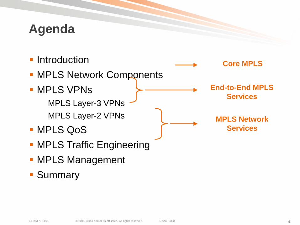
Agenda
Introduction
MPLS Network Components
MPLS VPNs
MPLS Layer-3 VPNs
MPLS Layer-2 VPNs
MPLS QoS
MPLS Traffic Engineering
MPLS Management
Summary
Core MPLS
End-to-End MPLS
Services
MPLS Network
Services

© 2011 Cisco and/or its affiliates. All rights reserved. Cisco PublicBRKMPL-1101 5
IntroductionThe Business Drivers for MPLS
© 2011 Cisco and/or its affiliates. All rights reserved. Cisco PublicBRKMPL-1101 6
Why Multi Protocol Label Switching?
SP/Carrier perspective
Reduce costs (CAPEX); consolidate networks
Consolidated network for multiple Layer-2/3 services
Support increasingly stringent SLAs
Handle increasing scale/complexity of IP-based services
Enterprise/end-user perspective
Campus/LAN
Need for network segmentation (users, applications, etc.)
WAN connectivity (connecting enterprise networks)
Need for easier configuration of site-to-site WAN connectivity

© 2011 Cisco and/or its affiliates. All rights reserved. Cisco PublicBRKMPL-1101 7
Evolution of MPLS
Evolved from tag switching in 1996 to full IETF standard, covering over 130 RFCs
Key application initially were Layer-3 VPNs, followed by Traffic Engineering (TE), and Layer-2 VPNs
1996 1997 1998 1999 2000 2001
Time
Cisco Calls a
BOF at IETF to
Standardize
Tag Switching
TE
Deployed
MPLS VPN
Deployed
Large Scale
Deployment
AToM
Cisco Ships
MPLS (Tag
Switching)
Cisco Ships
MPLS TE
MPLS Group
Formally Chartered
by IETF
2002 2003 2004+
Layer 2 Interworking
Bandwidth Protection
Interprovider Capabilities
MPLS OAM

© 2011 Cisco and/or its affiliates. All rights reserved. Cisco PublicBRKMPL-1101 8
What Is MPLS Technology?
It’s all about labels …
Use the best of both worlds
Layer-2 (ATM/FR): efficient forwarding and traffic engineering
Layer-3 (IP): flexible and scalable
MPLS forwarding plane
Use of labels for forwarding Layer-2/3 data traffic
Labeled packets are being switched instead of routed
Leverage layer-2 forwarding efficiency
MPLS control/signaling plane
Use of existing IP control protocols extensions + new protocols to exchange label information
Leverage layer-3 control protocol flexibility and scalability
© 2011 Cisco and/or its affiliates. All rights reserved. Cisco PublicBRKMPL-1101 9
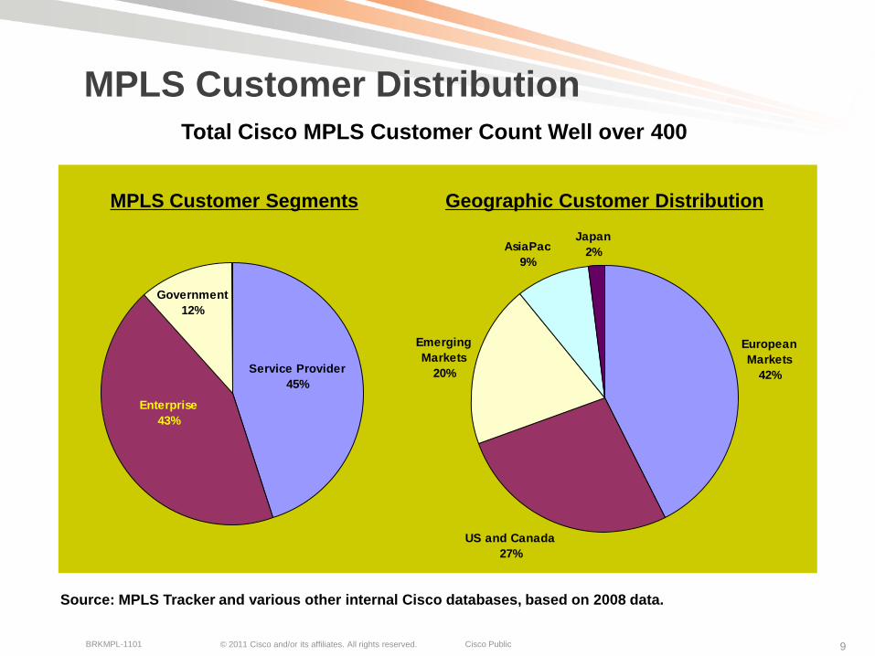
MPLS Customer Distribution
Government
12%
Service Provider
45%
Enterprise
43%
MPLS Customer Segments
AsiaPac
9%
Japan
2%
European
Markets
42%
US and Canada
27%
Emerging
Markets
20%
Geographic Customer Distribution
Source: MPLS Tracker and various other internal Cisco databases, based on 2008 data.
Total Cisco MPLS Customer Count Well over 400

© 2011 Cisco and/or its affiliates. All rights reserved. Cisco PublicBRKMPL-1101 10
MPLS Enterprise Customer Segments
25
20
13 13
109
7
3 3 32 2
1 1 1 1 10
5
10
15
20
25
30
Finan
cial
Trans
porta
tion
Syste
m In
tegr
ator
Educa
tion/
Res
earc
h
Energ
y
Insu
ranc
e
Man
ufac
turin
g
Ret
ail
Con
glom
erat
e
Inte
rnal IT
Con
tent
Pro
vide
r
CRM
Def
ense
Med
ia/E
nter
tainm
ent
Pharm
aceu
tical
Gov
ernm
ent
Hea
lthca
re
Enterprise Customer Segments
% o
f T
ota
l M
PL
S E
nte
rpri
se C
usto
mer
Base
Financials, Transportation, and System Integrators are currently biggest
enterprise customer segments for MPLS
Source: MPLS Tracker and various other internal Cisco databases, based on 2008 data.

© 2011 Cisco and/or its affiliates. All rights reserved. Cisco PublicBRKMPL-1101 11
Enterprise MPLS Customers
Two types of enterprise customers for MPLS technology
MPLS indirectly used as subscribed WAN service
Enterprise subscribes to WAN connectivity data service offered by external Service Provider
Data connectivity service implemented by Service Provider via MPLS VPN technology (e.g., layer-2 and layer-3 VPNs)
VPN Service can be managed or unmanaged
MPLS used as part of self managed network
Enterprise deploys MPLS in it’s own network
Enterprise manages it’s own MPLS-based network

© 2011 Cisco and/or its affiliates. All rights reserved. Cisco PublicBRKMPL-1101 12
Enterprise MPLS Drivers
Network segmentation
Network virtualization
Distributed application virtualization
Network realignment/migration
Consolidation of (multiple) legacy networks
Staged network consolidation after company merger/acquisition
Network Optimization
Full-mesh and hub-and-spoke connectivity
Traffic Engineering (TE) for bandwidth protection

© 2011 Cisco and/or its affiliates. All rights reserved. Cisco PublicBRKMPL-1101 15
MPLS Technology ComponentsBasic Building Blocks of MPLS
© 2011 Cisco and/or its affiliates. All rights reserved. Cisco PublicBRKMPL-1101 16
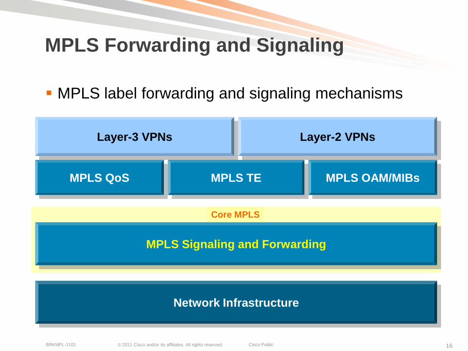
MPLS Forwarding and Signaling
MPLS label forwarding and signaling mechanisms
Network Infrastructure
MPLS Signaling and Forwarding
Layer-3 VPNs Layer-2 VPNs
MPLS QoS MPLS OAM/MIBsMPLS TE
Core MPLS

© 2011 Cisco and/or its affiliates. All rights reserved. Cisco PublicBRKMPL-1101 17
Basic Building Blocks
The big picture
MPLS-enabled network devices
Label Switched Paths (LSPs)
The internals
MPLS labels
Processing of MPLS labels
Exchange of label mapping information
Forwarding of labeled packets
Other related protocols and protocols to exchange label information
Between MPLS-enabled devices

© 2011 Cisco and/or its affiliates. All rights reserved. Cisco PublicBRKMPL-1101 18
MPLS Domain
MPLS Network Overview
P (Provider) router = label switching router = core router (LSR)
Switches MPLS-labeled packets
PE (Provider Edge) router = edge router (LSR)
Imposes and removes MPLS labels
CE (Customer Edge) router
Connects customer network to MPLS network
CE
CE
CE
CE
Label switched traffic
P
P
P
P
PE
PE PE
PE
© 2011 Cisco and/or its affiliates. All rights reserved. Cisco PublicBRKMPL-1101 19
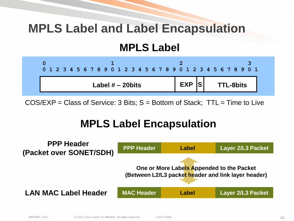
MPLS Label and Label Encapsulation
COS/EXP = Class of Service: 3 Bits; S = Bottom of Stack; TTL = Time to Live
0 1 2 3
0 1 2 3 4 5 6 7 8 9 0 1 2 3 4 5 6 7 8 9 0 1 2 3 4 5 6 7 8 9 0 1
Label # – 20bits EXP S TTL-8bits
MPLS Label
LabelPPP Header Layer 2/L3 PacketPPP Header
(Packet over SONET/SDH)
MPLS Label Encapsulation
One or More Labels Appended to the Packet
(Between L2/L3 packet header and link layer header)
LAN MAC Label Header LabelMAC Header Layer 2/L3 Packet
© 2011 Cisco and/or its affiliates. All rights reserved. Cisco PublicBRKMPL-1101 20
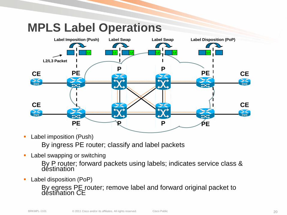
MPLS Label Operations
Label imposition (Push)
By ingress PE router; classify and label packets
Label swapping or switching
By P router; forward packets using labels; indicates service class & destination
Label disposition (PoP)
By egress PE router; remove label and forward original packet to destination CE
CE
CE
CE
CE
PP PE
PE
PE
L1
Label Imposition (Push)
L2/L3 Packet
L1 L2
Label Swap
P
L2 L3
Label Swap
PE
L3
Label Disposition (PoP)
P
© 2011 Cisco and/or its affiliates. All rights reserved. Cisco PublicBRKMPL-1101 21
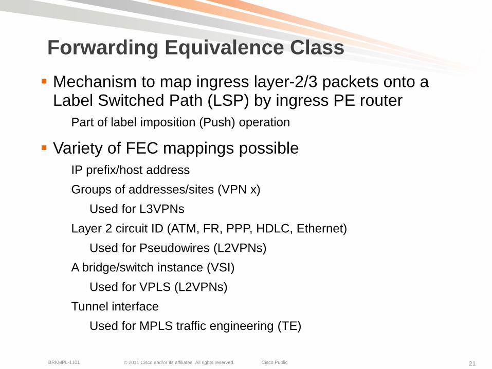
Forwarding Equivalence Class
Mechanism to map ingress layer-2/3 packets onto a Label Switched Path (LSP) by ingress PE router
Part of label imposition (Push) operation
Variety of FEC mappings possible
IP prefix/host address
Groups of addresses/sites (VPN x)
Used for L3VPNs
Layer 2 circuit ID (ATM, FR, PPP, HDLC, Ethernet)
Used for Pseudowires (L2VPNs)
A bridge/switch instance (VSI)
Used for VPLS (L2VPNs)
Tunnel interface
Used for MPLS traffic engineering (TE)

© 2011 Cisco and/or its affiliates. All rights reserved. Cisco PublicBRKMPL-1101 22
Label Distribution Protocol
MPLS nodes need to exchange label information with each other
Ingress PE node (Push operation)
Needs to know what label to use for a given FEC to send packet to neighbor
Core P node (Swap operation)
Needs to know what label to use for swap operation for incoming labeled packets
Egress PE node (Pop operation)
Needs to tell upstream neighbor what label to use for specific FEC type LDP used for exchange of label (mapping) information
Label Distribution Protocol (LDP)Defined in RFC 3035 and RFC3036; updated by RFC5036
LDP is a superset of the Cisco-specific Tag Distribution Protocol
Note that, in addition LDP, also other protocols are being used for label information exchange
Will be discussed later

© 2011 Cisco and/or its affiliates. All rights reserved. Cisco PublicBRKMPL-1101 23
Some More LDP Details
Assigns, distributes, and installs (in forwarding) labels for prefixes advertised by unicast routing protocols
OSPF, IS-IS, EIGRP, etc.
Also used for Pseudowire/PW (VC) signalingUsed for L2VPN control plane signaling
Uses UDP (port 646) for session discovery and TCP (port 646) for exchange of LDP messages
LDP operationsLDP Peer Discovery
LDP Session Establishment
MPLS Label Allocation, Distribution, and Updating MPLS forwarding
Information repositories used by LDP LIB: Label Information Database (read/write)
RIB: Routing Information Database/routing table (read-only)
For your
reference
only
© 2011 Cisco and/or its affiliates. All rights reserved. Cisco PublicBRKMPL-1101 24
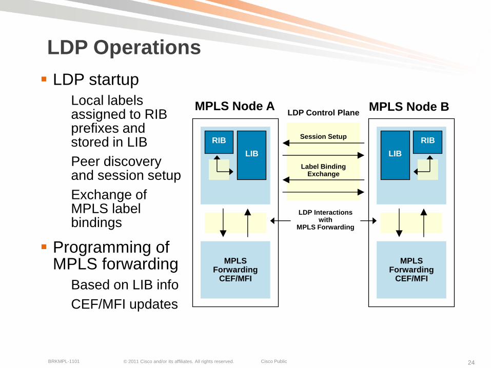
LDP Control PlaneMPLS Node A
LDP Operations
LDP startup
Local labels assigned to RIB prefixes and stored in LIB
Peer discovery and session setup
Exchange of MPLS label bindings
Programming of MPLS forwarding
Based on LIB info
CEF/MFI updates
MPLS Node B
Session Setup
Label Binding Exchange
MPLS Forwarding
CEF/MFI
RIB
LIB
MPLS Forwarding
CEF/MFI
LDP Interactions with
MPLS Forwarding
LIB
RIB
© 2011 Cisco and/or its affiliates. All rights reserved. Cisco PublicBRKMPL-1101 25
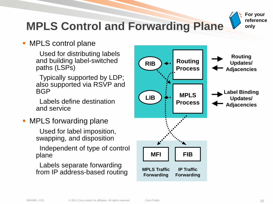
MPLS Control and Forwarding Plane
MPLS control plane
Used for distributing labels and building label-switched paths (LSPs)
Typically supported by LDP; also supported via RSVP and BGP
Labels define destination and service
MPLS forwarding plane
Used for label imposition, swapping, and disposition
Independent of type of control plane
Labels separate forwarding from IP address-based routing
LIB
Routing
Updates/
Adjacencies
MFI
MPLS Traffic
Forwarding
FIB
MPLS
Process
Routing
ProcessRIB
Label Binding
Updates/
Adjacencies
IP Traffic
Forwarding
For your
reference
only

© 2011 Cisco and/or its affiliates. All rights reserved. Cisco PublicBRKMPL-1101 26
IP Packet Forwarding Example
0
1
1
128.89
171.69
0
128.89.25.4 Data
128.89.25.4 Data
128.89.25.4 Data
Packets Forwarded Based on IP Address (via RIB lookup)
…
128.89
171.69
Address
PrefixI/F
1
1
…
128.89
171.69
Address
PrefixI/F
0
1 …
128.89
171.69
Address
PrefixI/F
0
1
FIB FIB
FIB
128.89.25.4 Data
© 2011 Cisco and/or its affiliates. All rights reserved. Cisco PublicBRKMPL-1101 27
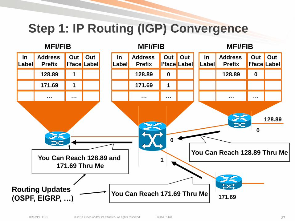
Step 1: IP Routing (IGP) Convergence
128.89
171.69
1
01
In
Label
Address
Prefix
…
Out
I’face
128.89 1
171.69 1
…
Out
Label
In
Label
Address
Prefix
…
Out
I’face
128.89 0
171.69 1
…
Out
Label
In
Label
Address
Prefix
128.89
…
Out
I’face
0
…
Out
Label
0
You Can Reach 171.69 Thru Me
You Can Reach 128.89 and
171.69 Thru Me
Routing Updates
(OSPF, EIGRP, …)
You Can Reach 128.89 Thru Me
MFI/FIB MFI/FIB MFI/FIB
0
1
1
0
© 2011 Cisco and/or its affiliates. All rights reserved. Cisco PublicBRKMPL-1101 28
1
128.89
01
0
171.69
In
Label
Address
Prefix
128.89
171.69
…
Out
I’face
1
1
…
Out
Label
In
Label
Address
Prefix
128.89
171.69
…
Out
I’face
0
1
…
Out
Label
In
Label
Address
Prefix
128.89
…
Out
I’face
0
…
Out
Label
…
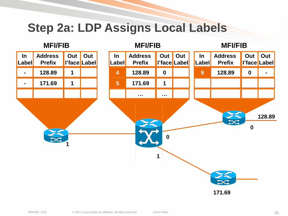
-
-
… …
4
5
…
-
…
9
…
Step 2a: LDP Assigns Local Labels
MFI/FIB MFI/FIB MFI/FIB
0
1
1
0

© 2011 Cisco and/or its affiliates. All rights reserved. Cisco PublicBRKMPL-1101 29
1
128.89
01
0
Use Label 9 for 128.89Use Label 4 for 128.89 and
Use Label 5 for 171.69
Label Distribution
Protocol (LDP)(Downstream Allocation)
171.69Use Label 7 for 171.69
In
Label
Address
Prefix
128.89
171.69
…
Out
I’face
1
1
…
Out
Label
In
Label
Address
Prefix
128.89
171.69
…
Out
I’face
0
1
…
Out
Label
In
Label
Address
Prefix
128.89
…
Out
I’face
0
…
Out
Label
4
5
…
-
-
…
9
7
…
4
5
…
-
…
9
…
Step 2b: LDP Assigns Remote Labels
MFI/FIB MFI/FIB MFI/FIB
0
1
1
0
© 2011 Cisco and/or its affiliates. All rights reserved. Cisco PublicBRKMPL-1101 30
1
0
1
128.89.25.4 Data 128.89.25.4 Data4
128.89.25.4 Data9
Label Switch Forwards
Based on Label
128.89.25.4 Data
128.890
171.69
In
Label
Address
Prefix
128.89
171.69
…
Out
I’face
1
1
…
Out
Label
In
Label
Address
Prefix
128.89
171.69
…
Out
I’face
0
1
…
Out
Label
In
Label
Address
Prefix
128.89
…
Out
I’face
0
…
Out
Label
4
5
…
-
-
…
9
7
…
4
5
…
-
…
9
…
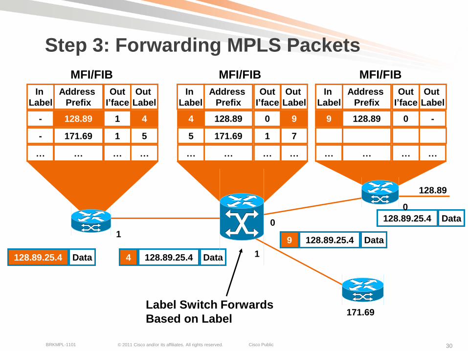
Step 3: Forwarding MPLS Packets
MFI/FIB MFI/FIB MFI/FIB
0
1
1
0

© 2011 Cisco and/or its affiliates. All rights reserved. Cisco PublicBRKMPL-1101 31
Summary Steps for MPLS Forwarding
Each node maintains IP routing information via IGP
IP routing table (RIB) and IP forwarding table (FIB)
LDP leverages IGP routing information
LDP label mapping exchange (between MPLS nodes) takes place after IGP has converged
LDP depends on IGP convergence
Label binding information stored in LIB
Once LDP has received remote label binding information MPLS forwarding is updated
Label bindings are received from remote LDP peers
MPLS forwarding via MFI

© 2011 Cisco and/or its affiliates. All rights reserved. Cisco PublicBRKMPL-1101 32
MPLS Network Protocols
IGP: OSPF, EIGRP, IS-IS on core facing and core links
RSVP and/or LDP on core and/or core facing links
MP-iBGP on PE devices (for MPLS services)
Label switched traffic
P
P
P
P
PE
PE PE
PE
OSPF, IS-IS,
EIGRP, EIGRP
LDP, RSVP
MP-iBGP
CE
CE
CE
CE

© 2011 Cisco and/or its affiliates. All rights reserved. Cisco PublicBRKMPL-1101 33
Label Stacking
More than one label can be used for MPLS packet encapsulationCreation of a label stack
Recap: labels correspond to Forwarding Equivalence Class (FEC)
Each label in stack used for different purposes
Outer label always used for switching MPLS packets in network
Remaining inner labels used to specific services/FECs, etc.
Last label in stack marked with EOS bit
Allows building services such as MPLS VPNs; LDP + VPN label
Traffic engineering (FRR): LDP + TE label
VPNs over TE core: LDP + TE + VPN label
Any transport over MPLS: LDP + PW label
TE Label
LDP Label
VPN Label
Inner Label
Outer Label
Layer 2/3
Packet Header
© 2011 Cisco and/or its affiliates. All rights reserved. Cisco PublicBRKMPL-1101 34
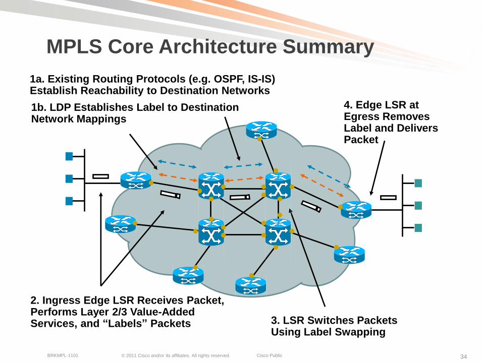
MPLS Core Architecture Summary
1a. Existing Routing Protocols (e.g. OSPF, IS-IS) Establish Reachability to Destination Networks
1b. LDP Establishes Label to Destination Network Mappings
2. Ingress Edge LSR Receives Packet, Performs Layer 2/3 Value-Added Services, and “Labels” Packets 3. LSR Switches Packets
Using Label Swapping
4. Edge LSR at Egress Removes Label and Delivers Packet
© 2011 Cisco and/or its affiliates. All rights reserved. Cisco PublicBRKMPL-1101 35
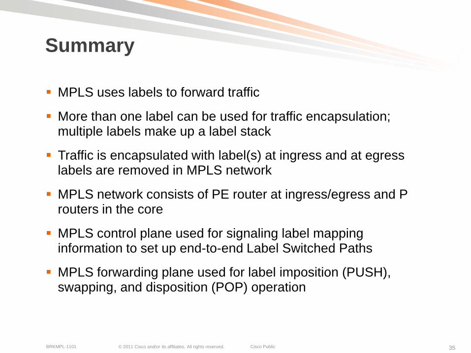
Summary
MPLS uses labels to forward traffic
More than one label can be used for traffic encapsulation; multiple labels make up a label stack
Traffic is encapsulated with label(s) at ingress and at egress labels are removed in MPLS network
MPLS network consists of PE router at ingress/egress and P routers in the core
MPLS control plane used for signaling label mapping information to set up end-to-end Label Switched Paths
MPLS forwarding plane used for label imposition (PUSH), swapping, and disposition (POP) operation

© 2011 Cisco and/or its affiliates. All rights reserved. Cisco PublicBRKMPL-1101 36
MPLS VPNsOverview

© 2011 Cisco and/or its affiliates. All rights reserved. Cisco PublicBRKMPL-1101 37
MPLS Technology Framework
End-to-end data connectivity services across MPLS networks (from PE to PE)
Network Infrastructure
MPLS Signaling and Forwarding
Layer-3 VPNs Layer-2 VPNs
MPLS QoS MPLS OAM/MIBsMPLS TE
End-to-end Services

© 2011 Cisco and/or its affiliates. All rights reserved. Cisco PublicBRKMPL-1101 38
What Is a Virtual Private Network?
VPN is a set of sites or groups which are allowed to communicate with each other in a secure way
Typically over a shared public or private network infrastructure
VPN is defined by a set of administrative policiesPolicies established by VPN customers themselves (DIY)Policies implemented by VPN service provider (managed/unmanaged)
Different inter-site connectivity schemes possibleRanging from complete to partial mesh, hub-and-spoke
Sites may be either within the same or in different organizations
VPN can be either intranet or extranet
Site may be in more than one VPNVPNs may overlap
Not all sites have to be connected to the same service provider
VPN can span multiple providers

© 2011 Cisco and/or its affiliates. All rights reserved. Cisco PublicBRKMPL-1101 39
MPLS VPN Example
PE-CE link
Connect customer network to MPLS network; layer-2 or layer-3
VPN
Dedicated secure connectivity over shared infrastructure
Label switched traffic
P
P
P
P
PE
PE PE
PECE
CE
CE
CE
VPN
PE-CE
Link
PE-CE
Link
© 2011 Cisco and/or its affiliates. All rights reserved. Cisco PublicBRKMPL-1101 40
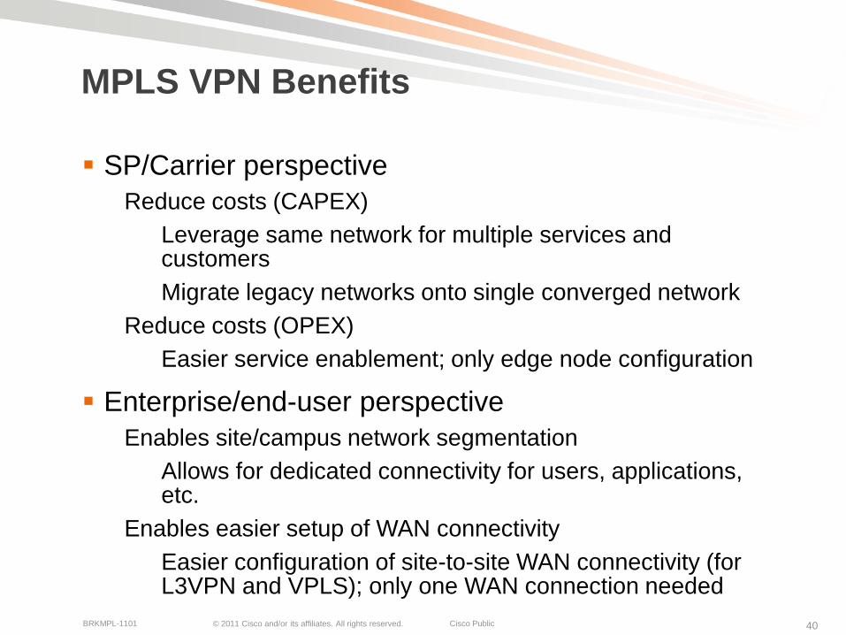
MPLS VPN Benefits
SP/Carrier perspective
Reduce costs (CAPEX)
Leverage same network for multiple services and customers
Migrate legacy networks onto single converged network
Reduce costs (OPEX)
Easier service enablement; only edge node configuration
Enterprise/end-user perspective
Enables site/campus network segmentation
Allows for dedicated connectivity for users, applications, etc.
Enables easier setup of WAN connectivity
Easier configuration of site-to-site WAN connectivity (for L3VPN and VPLS); only one WAN connection needed

© 2011 Cisco and/or its affiliates. All rights reserved. Cisco PublicBRKMPL-1101 41
MPLS VPN Models
MPLS VPN Options
• CPE connected to PE via IP-based connection
(over any layer-2 type)
– Static routing
– PE-CE routing protocol; eBGP, OSPF, IS-IS
• CEs peer with PE router
• PE routers maintain customer-specific routing
tables and exchange customer=specific routing
information
• Layer-3 VPN provider’s PE routers are part of
customer routing
Layer-3 VPNsLayer-2 VPNs
Point-to-PointLayer-2 VPNs
Multi-PointLayer-2 VPNs
• CPE connected to
PE via p2p Layer-2
connection (FR,
ATM)
• CEs peer with each
other (IP routing)
via p2p layer-2 VPN
connection
• CE-CE routing; no
SP involvement
• CPE connected to
PE via Ethernet
connection (VLAN)
• CEs peer with each
other via
fully/partial mesh
Layer-2 VPN
connection
• CE-CE routing; no
SP involvement
© 2011 Cisco and/or its affiliates. All rights reserved. Cisco PublicBRKMPL-1101 42
MPLS Layer-3 VPNsTechnology Overview and Applications
© 2011 Cisco and/or its affiliates. All rights reserved. Cisco PublicBRKMPL-1101 43
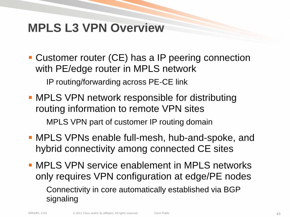
MPLS L3 VPN Overview
Customer router (CE) has a IP peering connection with PE/edge router in MPLS network
IP routing/forwarding across PE-CE link
MPLS VPN network responsible for distributing routing information to remote VPN sites
MPLS VPN part of customer IP routing domain
MPLS VPNs enable full-mesh, hub-and-spoke, and hybrid connectivity among connected CE sites
MPLS VPN service enablement in MPLS networks only requires VPN configuration at edge/PE nodes
Connectivity in core automatically established via BGP signaling
© 2011 Cisco and/or its affiliates. All rights reserved. Cisco PublicBRKMPL-1101 44
MPLS L3 VPN Technology Components
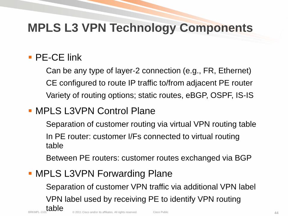
PE-CE link
Can be any type of layer-2 connection (e.g., FR, Ethernet)
CE configured to route IP traffic to/from adjacent PE router
Variety of routing options; static routes, eBGP, OSPF, IS-IS
MPLS L3VPN Control Plane
Separation of customer routing via virtual VPN routing table
In PE router: customer I/Fs connected to virtual routing table
Between PE routers: customer routes exchanged via BGP
MPLS L3VPN Forwarding Plane
Separation of customer VPN traffic via additional VPN label
VPN label used by receiving PE to identify VPN routing table

© 2011 Cisco and/or its affiliates. All rights reserved. Cisco PublicBRKMPL-1101 45
Virtual Routing and Forwarding Instance
Virtual Routing and Forwarding Instance (VRF)
Typically one VRF created for each customer VPN on PE router
VRF associated with one or more customer interfaces
VRF has its own instance of routing table (RIB) and forwarding table (CEF)
VRF has its own instance for PE-CE configured routing protocols
VRF Blue
VRF GreenCE
PE
CE
VPN 2
VPN 1
MPLS Backbone IGP

© 2011 Cisco and/or its affiliates. All rights reserved. Cisco PublicBRKMPL-1101 46
VPN Route Distribution
Full mesh of BGP sessions among all PE routers
Multi-Protocol BGP extensions (MP-iBGP)
Typically BGP Route Reflector (RR) used for improved scalability
Label switched traffic
P
P
P
P
PE
PE PE
PECE
CE
CE
CE
Customer
Route
Exchange
Customer
Route
Exchange
VPN Route Exchange
BGP RR
VRF VRF
VPN 2
VRF VRF
VPN 1
MP-iBGP Session

© 2011 Cisco and/or its affiliates. All rights reserved. Cisco PublicBRKMPL-1101 47
VPN Control Plane Processing
Make customer routes unique:
Route Distinguisher (RD): 8-byte field, VRF parameters; unique value assigned by a provider to each VPN to make different VPN routes unique
VPNv4 address: RD+VPN IP prefix
Selective distribute customer routes:
Route Target (RT): 8-byte field, VRF parameter, unique value to define the import/export rules for VPNv4 routes
MP-iBGP: advertises VPNv4* prefixes + labels
Processing Steps:
1. CE1 redistribute IPv4 route to PE1 via eBGP.
2. PE1 allocates VPN label for prefix learnt from CE1 to create unique VPNv4 route
3. PE1 redistributes VPNv4 route into MP-iBGP, it sets itself as a next hop and relays VPN site routes to PE2
4. PE2 receives VPNv4 route and, via processing in local VRF (green), it redistributes original IPv4 route to CE2.
PPPE1 PE2CE1 CE2
ip vrf Green
RD 1:100
route-target export 1:100
route-target import 1:100
No VPN Routes in core (P) nodes
eBGP:
16.1/16 IP Subnet
BGP advertisement:
VPN-IPv4 Addr = RD:16.1/16
BGP Next-Hop = PE1
Route Target = 100:1
Label=42 eBGP:
16.1/16 IP Subnet
VRF VRFVPN 1
© 2011 Cisco and/or its affiliates. All rights reserved. Cisco PublicBRKMPL-1101 48
VPN Forwarding Plane Processing
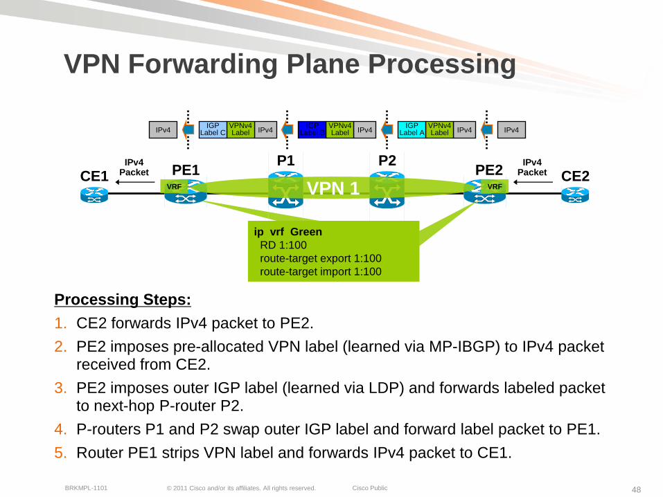
Processing Steps:
1. CE2 forwards IPv4 packet to PE2.
2. PE2 imposes pre-allocated VPN label (learned via MP-IBGP) to IPv4 packet received from CE2.
3. PE2 imposes outer IGP label (learned via LDP) and forwards labeled packet to next-hop P-router P2.
4. P-routers P1 and P2 swap outer IGP label and forward label packet to PE1.
5. Router PE1 strips VPN label and forwards IPv4 packet to CE1.
P2P1PE1 PE2CE1 CE2
ip vrf Green
RD 1:100
route-target export 1:100
route-target import 1:100
IPv4Packet
VRF VRFVPN 1
IPv4Packet
IPv4IPv4VPNv4Label
IGPLabel AIPv4
VPNv4Label
IGPLabel BIPv4
VPNv4Label
IGPLabel CIPv4
© 2011 Cisco and/or its affiliates. All rights reserved. Cisco PublicBRKMPL-1101 49
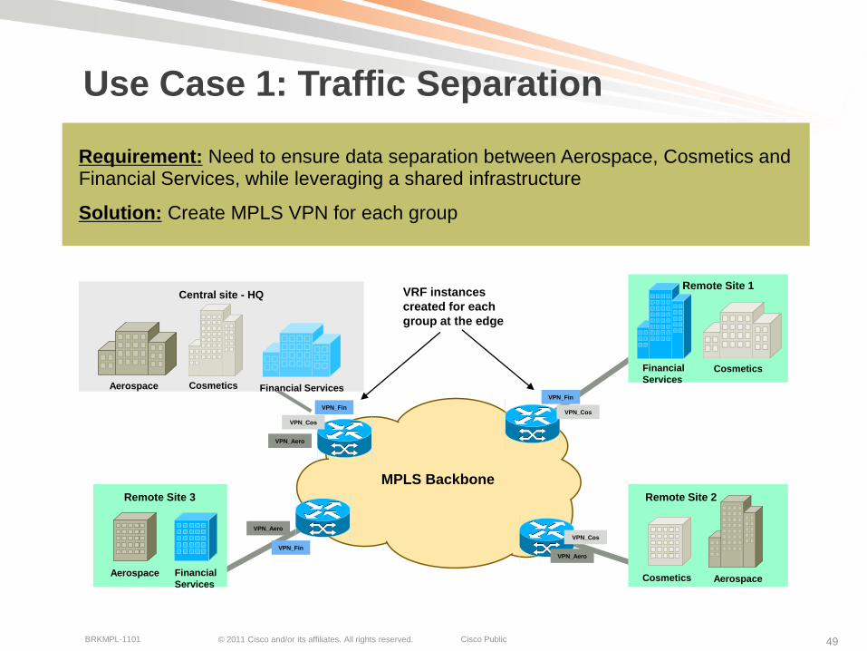
Use Case 1: Traffic Separation
Requirement: Need to ensure data separation between Aerospace, Cosmetics and Financial Services, while leveraging a shared infrastructure
Solution: Create MPLS VPN for each group
Aerospace Cosmetics Financial Services
Central site - HQ
CosmeticsFinancial
Services
Remote Site 1
AerospaceCosmetics
Remote Site 2
Aerospace Financial
Services
Remote Site 3
VPN_Fin
VPN_Fin
VPN_Fin
VPN_Cos
VPN_Cos
VPN_Cos
VPN_Aero
VPN_Aero
VPN_Aero
MPLS Backbone
VRF instances
created for each
group at the edge
© 2011 Cisco and/or its affiliates. All rights reserved. Cisco PublicBRKMPL-1101 50
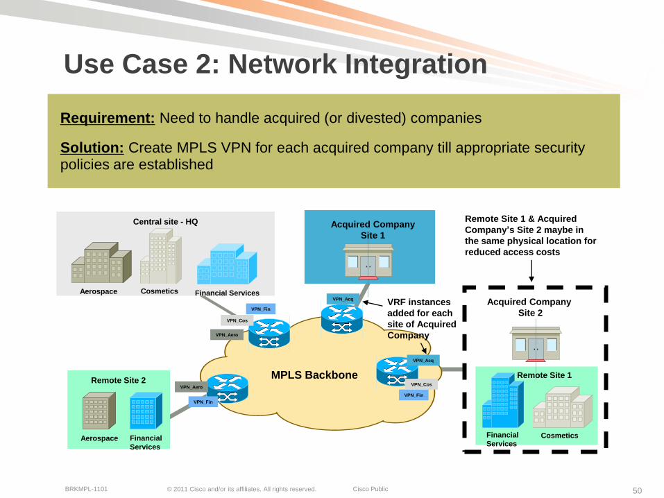
Use Case 2: Network Integration
Requirement: Need to handle acquired (or divested) companies
Solution: Create MPLS VPN for each acquired company till appropriate security policies are established
Aerospace Cosmetics Financial Services
Central site - HQ
CosmeticsFinancial
Services
Remote Site 1
Aerospace Financial
Services
Remote Site 2
VPN_Fin
VPN_Cos
VPN_Aero
VPN_Fin
VPN_Aero
VPN_Fin
VPN_Cos
MPLS Backbone
Acquired Company
Site 2
Acquired Company
Site 1
VPN_Acq
VRF instances
added for each
site of Acquired
Company
VPN_Acq
Remote Site 1 & Acquired
Company’s Site 2 maybe in
the same physical location for
reduced access costs

© 2011 Cisco and/or its affiliates. All rights reserved. Cisco PublicBRKMPL-1101 51
Use Case 3: Shared Access to Services
Requirement: To resell information (based on raw data) to other companies
Solution: Enterprise needs to become an ―Information Provider‖. Solution set similar to Service Providers – MPLS VPNs
“Information Provider XYZ”
Company “A”
Site 1
Company “B”
Company “A”
Site 2
VPN_A
VPN_A
VPN_A
VPN_B
VPN_BMPLS Backbone
VRF instances
created for each
“subscriber”
company
Company “B” and Company “A”
Site 2 maybe in the same physical
location for reduced access costs
Company “A” and Company “B” access
“Information Provider XYZ” for analysis, reports, trends, etc.

© 2011 Cisco and/or its affiliates. All rights reserved. Cisco PublicBRKMPL-1101 52
Use Case 4: Simplify Hub Site Design
Requirement: To ease the scale and design of head-end site
Solution: Implement MPLS Layer 3 VPNs, which reduces the number of routing peers of the central site
Without MPLS
Central Site
Remote Sites
Central site has high
number of routing
peers – creates a
complicated
headend design
With MPLS
Central Site
Remote Sites
Central site has
a single routing
peer – enhancing
head-end design
MPLS Backbone

© 2011 Cisco and/or its affiliates. All rights reserved. Cisco PublicBRKMPL-1101 53
Enterprise Network Architecture
Access
Distribution
Core
Internet
For your
reference
only
© 2011 Cisco and/or its affiliates. All rights reserved. Cisco PublicBRKMPL-1101 54
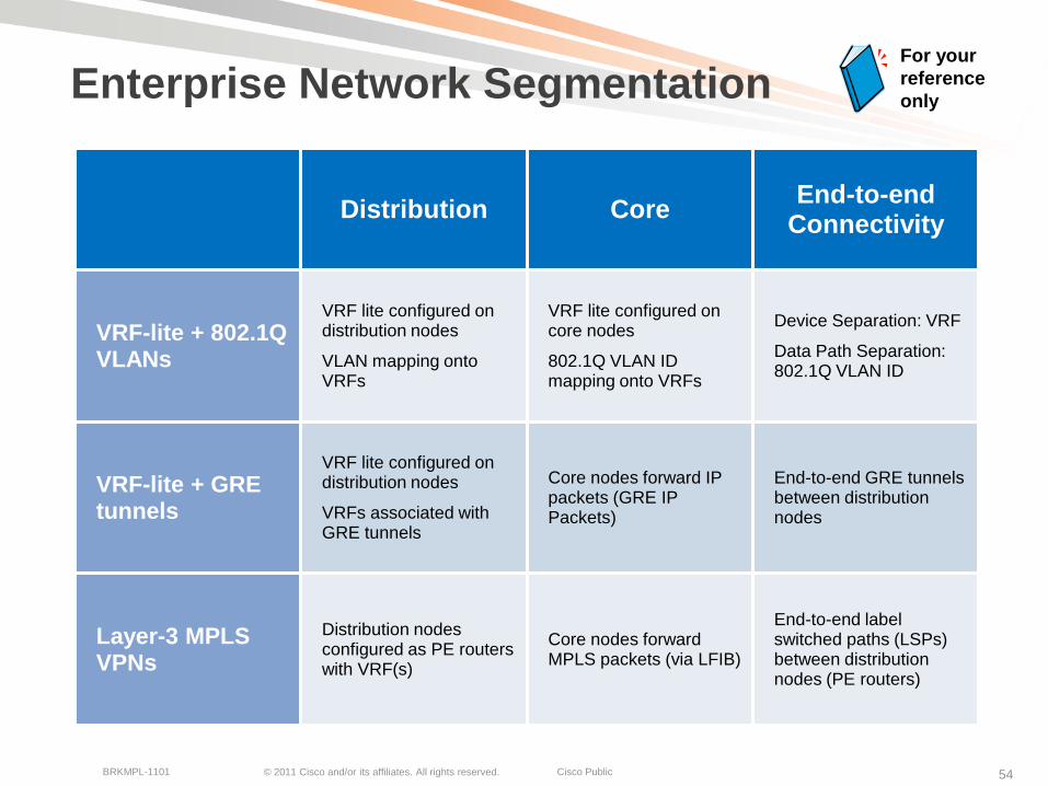
Enterprise Network Segmentation
Distribution CoreEnd-to-end
Connectivity
VRF-lite + 802.1Q VLANs
VRF lite configured on distribution nodes
VLAN mapping onto VRFs
VRF lite configured on core nodes
802.1Q VLAN ID mapping onto VRFs
Device Separation: VRF
Data Path Separation: 802.1Q VLAN ID
VRF-lite + GRE tunnels
VRF lite configured on distribution nodes
VRFs associated with GRE tunnels
Core nodes forward IP packets (GRE IP Packets)
End-to-end GRE tunnels between distribution nodes
Layer-3 MPLS VPNs
Distribution nodes configured as PE routers with VRF(s)
Core nodes forward MPLS packets (via LFIB)
End-to-end label switched paths (LSPs) between distribution nodes (PE routers)
For your
reference
only
© 2011 Cisco and/or its affiliates. All rights reserved. Cisco PublicBRKMPL-1101 55
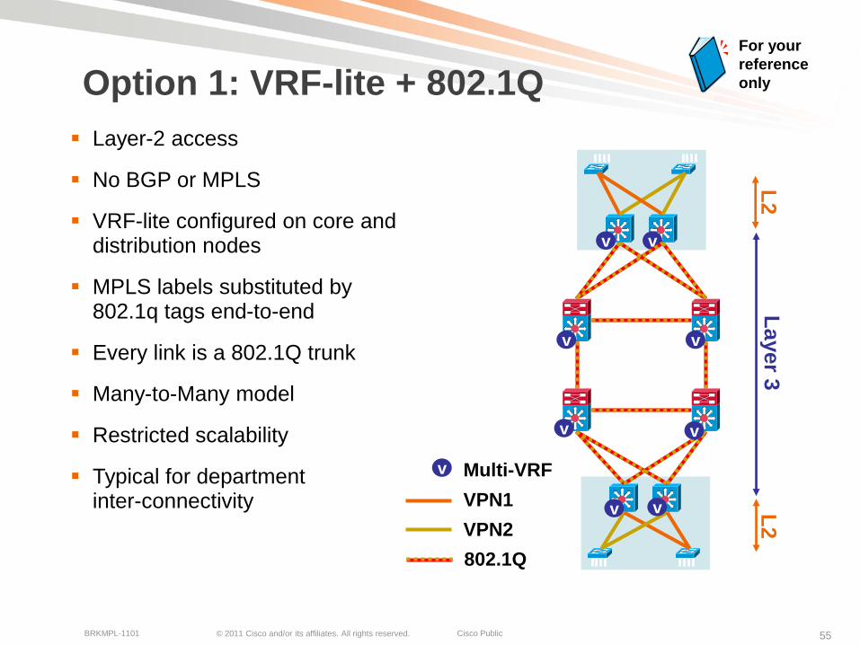
Option 1: VRF-lite + 802.1Q
Layer-2 access
No BGP or MPLS
VRF-lite configured on core and distribution nodes
MPLS labels substituted by 802.1q tags end-to-end
Every link is a 802.1Q trunk
Many-to-Many model
Restricted scalability
Typical for department inter-connectivity
vv
v v
v
Layer 3
L2
L2
v
v
v
v
802.1Q
Multi-VRF
VPN1
VPN2
For your
reference
only

© 2011 Cisco and/or its affiliates. All rights reserved. Cisco PublicBRKMPL-1101 56
Option 2: VRF-lite + GRE
L2 access
No BGP or MPLS
VRF-lite only configured on distribution nodes
VLANs associated with end-to-end GRE Tunnels
Many-to-One model
Restricted scalability
Typical for user-specific VPN connectivity
vv
v v
v
Layer 3
L2
L2
GRE
Multi-VRF
VPN1
VPN2
For your
reference
only
© 2011 Cisco and/or its affiliates. All rights reserved. Cisco PublicBRKMPL-1101 57
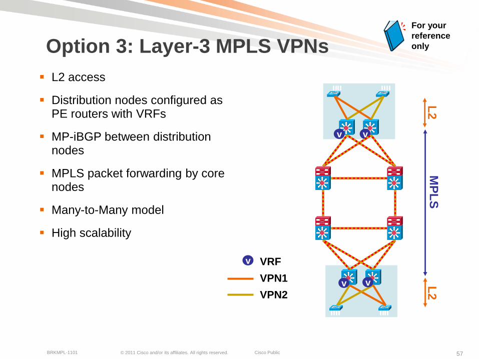
Option 3: Layer-3 MPLS VPNs
L2 access
Distribution nodes configured as PE routers with VRFs
MP-iBGP between distribution nodes
MPLS packet forwarding by core nodes
Many-to-Many model
High scalability
vv
v v
v
MP
LS
L2
L2
VRF
VPN1
VPN2
For your
reference
only

© 2011 Cisco and/or its affiliates. All rights reserved. Cisco PublicBRKMPL-1101 58
MPLS Layer-3 VPN Summary
Provide layer-3 connectivity among CE sites via IP peering (across PE-CE link)
Implemented via VRFs on edge/PE nodes providing customer route and forwarding segmentation
BGP used for control plane to exchange customer VPN (VPNv4) routes between PE routers
MPLS VPNs enable full-mesh, hub-and-spoke, and hybrid IP connectivity among connected CE sites
L3 VPNs for enterprise network segmentation can also be implemented via VRFs + GRE tunnels or VLANs

© 2011 Cisco and/or its affiliates. All rights reserved. Cisco PublicBRKMPL-1101 59
MPLS Layer-2 VPNsTechnology Overview and Applications
© 2011 Cisco and/or its affiliates. All rights reserved. Cisco PublicBRKMPL-1101 60
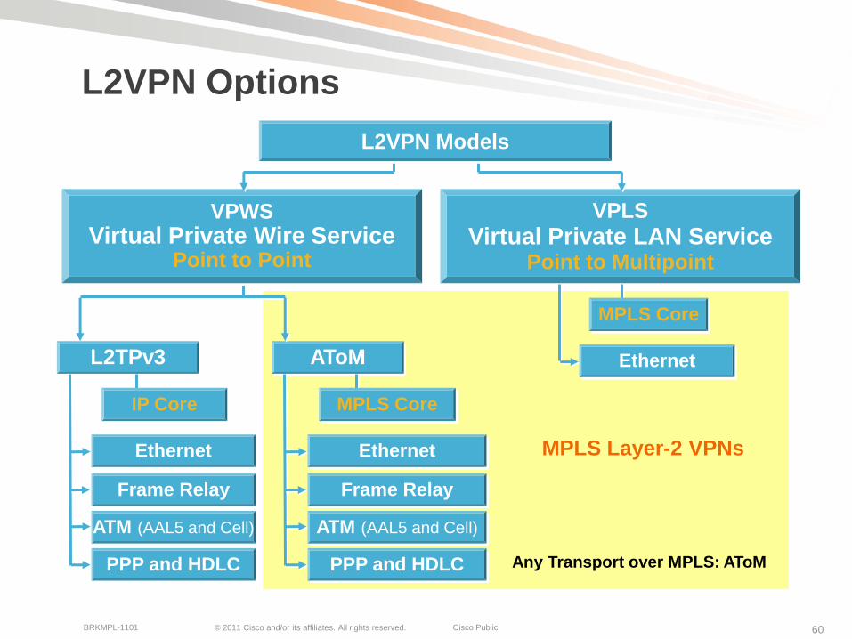
MPLS Layer-2 VPNs
L2VPN Options
VPLS
Virtual Private LAN ServicePoint to Multipoint
VPWS
Virtual Private Wire ServicePoint to Point
L2VPN Models
AToML2TPv3
IP Core
Frame Relay
ATM (AAL5 and Cell)
Ethernet
PPP and HDLC
MPLS Core
Frame Relay
ATM (AAL5 and Cell)
Ethernet
PPP and HDLC
MPLS Core
Ethernet
Any Transport over MPLS: AToM
© 2011 Cisco and/or its affiliates. All rights reserved. Cisco PublicBRKMPL-1101 61
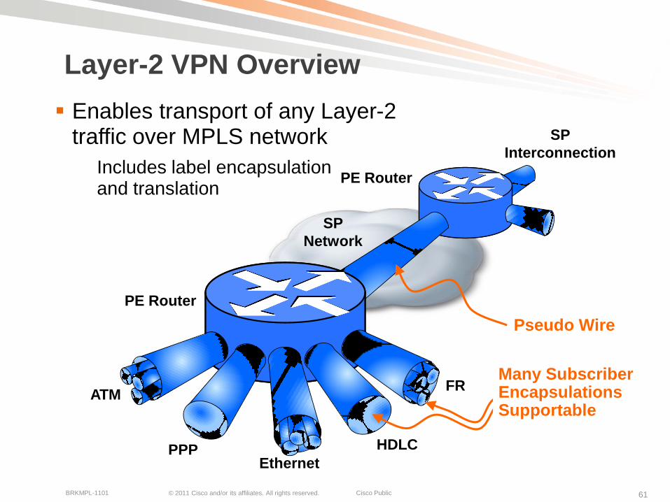
Layer-2 VPN Overview
Enables transport of any Layer-2 traffic over MPLS network
Includes label encapsulation and translation
Ethernet
ATM
HDLCPPP
FR
Pseudo Wire
SP
Network
SP
Interconnection
PE Router
PE Router
Many Subscriber Encapsulations Supportable
© 2011 Cisco and/or its affiliates. All rights reserved. Cisco PublicBRKMPL-1101 62
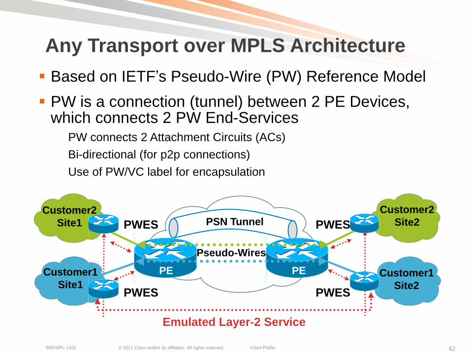
Any Transport over MPLS Architecture
Based on IETF’s Pseudo-Wire (PW) Reference Model
PW is a connection (tunnel) between 2 PE Devices, which connects 2 PW End-Services
PW connects 2 Attachment Circuits (ACs)
Bi-directional (for p2p connections)
Use of PW/VC label for encapsulation
Pseudo-Wires
Emulated Layer-2 Service
PWES PWES
PSN TunnelPWES PWES
Customer2
Site1
Customer1
Site1Customer1
Site2
PEPE
Customer2
Site2
© 2011 Cisco and/or its affiliates. All rights reserved. Cisco PublicBRKMPL-1101 63
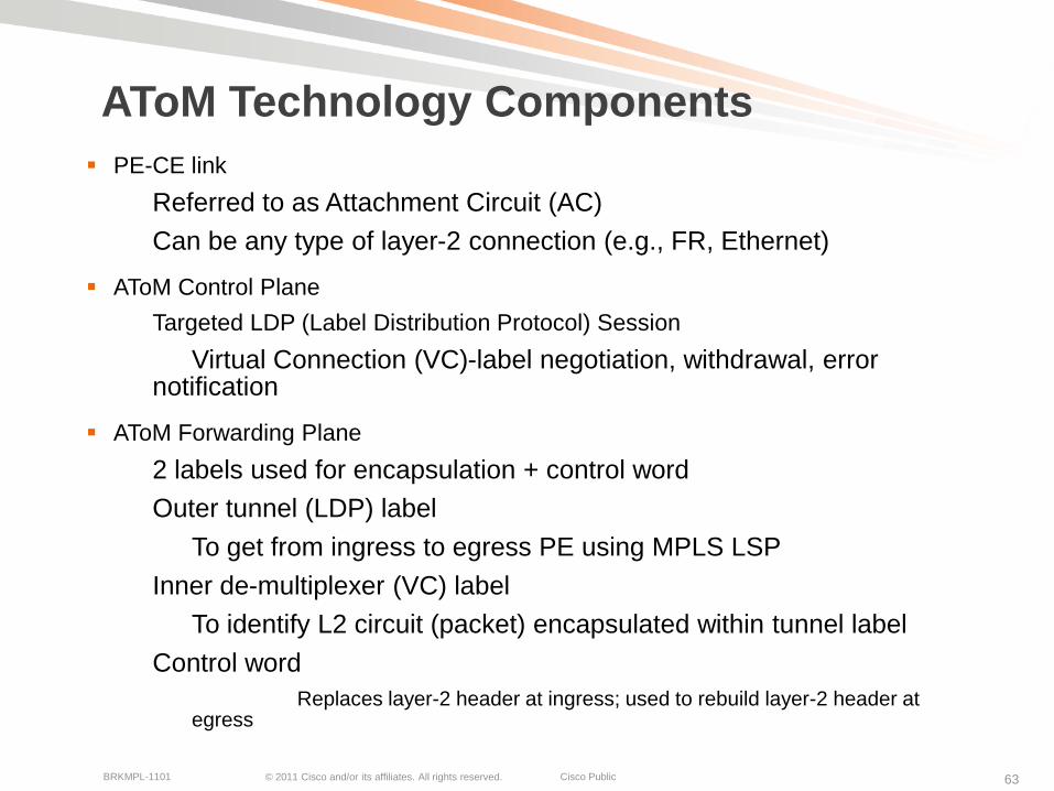
AToM Technology Components
PE-CE link
Referred to as Attachment Circuit (AC)
Can be any type of layer-2 connection (e.g., FR, Ethernet)
AToM Control Plane
Targeted LDP (Label Distribution Protocol) Session
Virtual Connection (VC)-label negotiation, withdrawal, error notification
AToM Forwarding Plane
2 labels used for encapsulation + control word
Outer tunnel (LDP) label
To get from ingress to egress PE using MPLS LSP
Inner de-multiplexer (VC) label
To identify L2 circuit (packet) encapsulated within tunnel label
Control word
Replaces layer-2 header at ingress; used to rebuild layer-2 header at egress

© 2011 Cisco and/or its affiliates. All rights reserved. Cisco PublicBRKMPL-1101 64
AToM Control Plane Processing
Processing Steps (for both P1 and P2):
1. CE1 and CE2 are connected to PE routers via layer-2 connections
2. Via CLI, a new virtual circuit cross-connect is configured, connecting customer interface to manually provided VC ID with target remote PE
3. New targeted LDP session between PE routers established, in case one does not already exist
4. PE binds VC label with customer layer-2 interface and sends label-mapping message to remote PE over LDP session
5. Remote PE receives LDP label binding message and matches VC ID with local configured cross-connect
PPPE1 PE2CE1 CE2
Layer-2Connection
Layer-2Connection
3 LDP session
4 Label Mapping Messages
2 2
55

© 2011 Cisco and/or its affiliates. All rights reserved. Cisco PublicBRKMPL-1101 65
AToM Forwarding Plane Processing
Processing Steps:
1. CE2 forwards layer-2 packet to PE2.
2. PE2 imposes VC (inner) label to layer-2 packet received from CE2 and optionally a control word as well (not shown).
3. PE2 imposes Tunnel outer label and forwards packet to P2.
4. P2 and P1 router forwards packet using outer (tunnel) label.
5. Router PE2 strips Tunnel label and, based on VC label, layer-2 packet is forwarded to customer interface to CE1, after VC label is removed
In case control word is used, new layer-2 header is generated first.
P2P1PE1 PE2CE1 CE2
Layer-2Packet
Layer-2Packet
L2L2VC
LabelTunnelLabel AL2
VCLabel
TunnelLabel BL2
VCLabel
TunnelLabel CL2

© 2011 Cisco and/or its affiliates. All rights reserved. Cisco PublicBRKMPL-1101 66
Use Case: L2 Network Interconnect
Requirement: Need to create connectivity between remote customer sites, currently interconnected via Frame Relay WAN connectivity. Only point-to-point connectivity required.
Solution: Interconnect AToM PW between sites, enabling transparent Frame Relay WAN connectivity.
PE1
MPLS Backbone
PE2
CPE Router,
FRAD
DLCI 101DLCI 201
Directed LDP
Label Exchange for VC1 – Label 10
Neighbor LDP–
Label 50
Neighbor LDP–
Label 90
101 10 50 101 10 90
VC1 – Connects DLCI 101
to DLCI 201
CPE Router,
FRAD
© 2011 Cisco and/or its affiliates. All rights reserved. Cisco PublicBRKMPL-1101 67
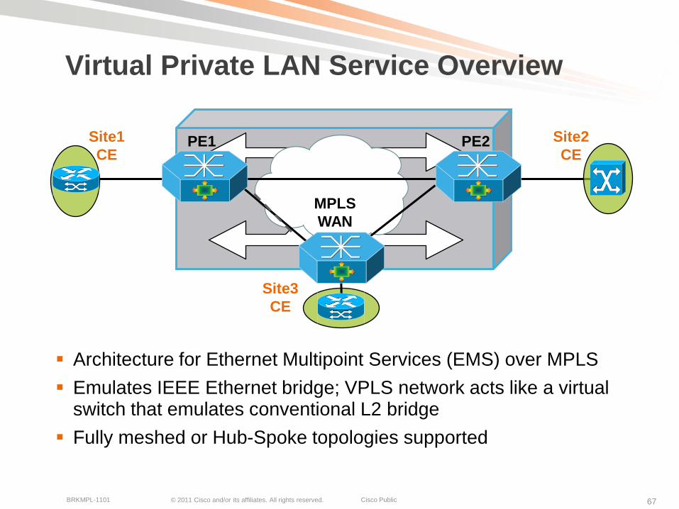
Virtual Private LAN Service Overview
Architecture for Ethernet Multipoint Services (EMS) over MPLS
Emulates IEEE Ethernet bridge; VPLS network acts like a virtual switch that emulates conventional L2 bridge
Fully meshed or Hub-Spoke topologies supported
PE1 PE2
MPLS
WAN
Site3
CE
Site2
CE
Site1
CE
© 2011 Cisco and/or its affiliates. All rights reserved. Cisco PublicBRKMPL-1101 68
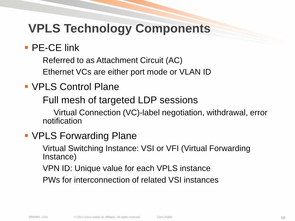
VPLS Technology Components
PE-CE link
Referred to as Attachment Circuit (AC)
Ethernet VCs are either port mode or VLAN ID
VPLS Control Plane
Full mesh of targeted LDP sessions
Virtual Connection (VC)-label negotiation, withdrawal, error notification
VPLS Forwarding Plane
Virtual Switching Instance: VSI or VFI (Virtual Forwarding Instance)
VPN ID: Unique value for each VPLS instance
PWs for interconnection of related VSI instances
© 2011 Cisco and/or its affiliates. All rights reserved. Cisco PublicBRKMPL-1101 69
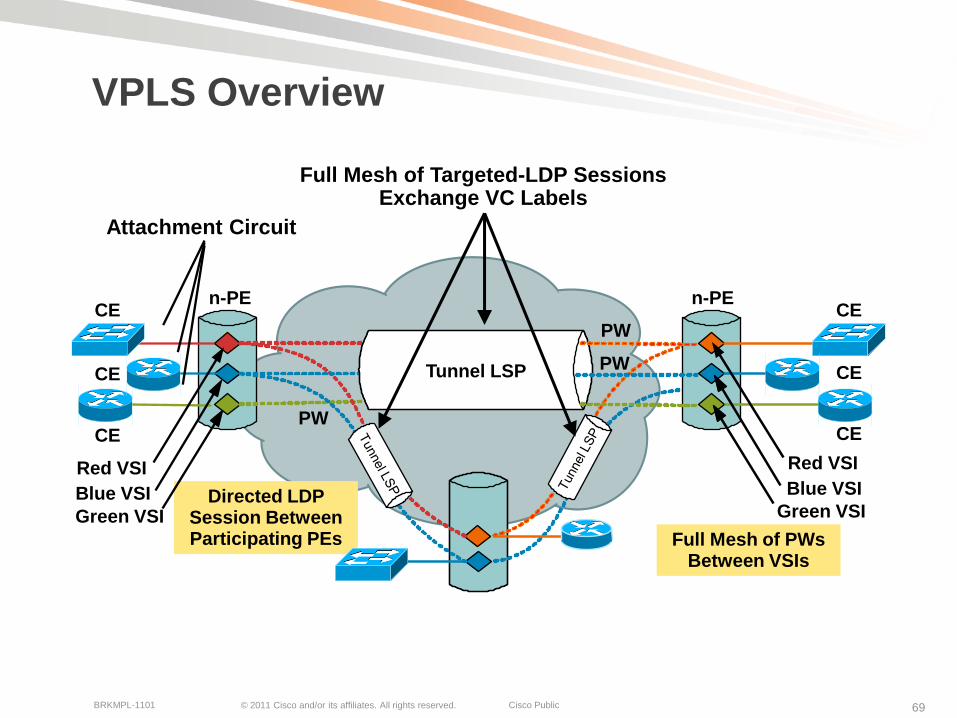
VPLS Overview
Full Mesh of PWs Between VSIs
Directed LDP Session Between Participating PEs
n-PE n-PE
PW
PW
PW
CE
CE
CE
CE
CE
CE
CE
Tunnel LSP
Green VSI
Blue VSI
Red VSI
Green VSI
Blue VSI
Red VSI
Attachment Circuit
Full Mesh of Targeted-LDP Sessions Exchange VC Labels

© 2011 Cisco and/or its affiliates. All rights reserved. Cisco PublicBRKMPL-1101 70
Use Case: VPLS Network Interconnect
Requirement: Need to create full-mesh connectivity between separate metro networks.
Solution: Use VPLS to create transparent bridge layer-2 Ethernet connectivity between ethernet networks.
Customer A1Metro
Ethernet
Carrier A
CE13
CE23
Metro
Backbone
Provider
PE1 PE2
Customer A1Customer A1
L2 Metro
Ethernet
Carrier A
CE11
CE21
L2 Metro
Ethernet
Carrier A
CE12
CE22
PE3
VPLS VPN Name: VPLS-CarrierA
VPN ID: 1100
VCID: 1234
Each PE points to other peer PE’s loopback address
QinQ
© 2011 Cisco and/or its affiliates. All rights reserved. Cisco PublicBRKMPL-1101 71
Layer-2 VPN Summary
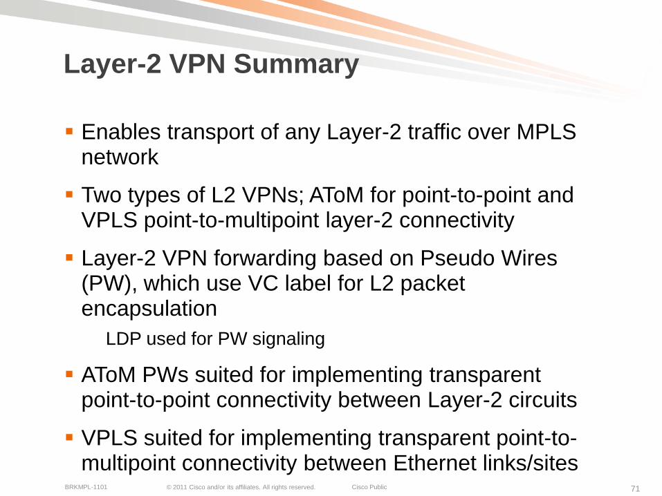
Enables transport of any Layer-2 traffic over MPLS network
Two types of L2 VPNs; AToM for point-to-point and VPLS point-to-multipoint layer-2 connectivity
Layer-2 VPN forwarding based on Pseudo Wires (PW), which use VC label for L2 packet encapsulation
LDP used for PW signaling
AToM PWs suited for implementing transparent point-to-point connectivity between Layer-2 circuits
VPLS suited for implementing transparent point-to-multipoint connectivity between Ethernet links/sites
© 2011 Cisco and/or its affiliates. All rights reserved. Cisco PublicBRKMPL-1101 72
MPLS QoSTechnology Overview and Applications

© 2011 Cisco and/or its affiliates. All rights reserved. Cisco PublicBRKMPL-1101 73
MPLS Technology Framework
MPLS QoS support for traffic marking and classification to enable differentiated services
Network Infrastructure
MPLS Signaling and Forwarding
Layer-3 VPNs Layer-2 VPNs
MPLS QoS MPLS OAM/MIBsMPLS TE
© 2011 Cisco and/or its affiliates. All rights reserved. Cisco PublicBRKMPL-1101 74
Why MPLS QoS?
Typically different traffic types (packets) sent over MPLS networks
E.g., Web HTTP, VoIP, FTP, etc.
Not all application traffic types/flows are the same …
Some require low latency to work correctly; e.g., VoIP
MPLS QoS used for traffic prioritization to guarantee minimal traffic loss and delay for high priority traffic
Involves packet classification and queuing
MPLS leverages mostly existing IP QoS architecture
Based on Differentiated Services (DiffServ) model; defines per-hop behavior based on IP Type of Service (ToS) field

© 2011 Cisco and/or its affiliates. All rights reserved. Cisco PublicBRKMPL-1101 75
MPLS QoS Operations
MPLS EXP bits used for packet classification and prioritization instead of IP Type of Service (ToS) field
DSCP values mapped into EXP bits at ingress PE router
Most providers provide 3–5 service classes
Different DSCP <-> EXP mapping schemes
Uniform mode, pipe mode, and short pipe mode
MPLS HeaderLayer-2 Header Layer 3 Header
MPLS DiffServ Marking
in Experimental BitsIP DiffServ Marking
EXP DSCP

© 2011 Cisco and/or its affiliates. All rights reserved. Cisco PublicBRKMPL-1101 76
MPLS Uniform Mode
End-to-end behavior: original IP DSCP value not preserved
At ingress PE, IP DSCP value copied in EXP value
EXP value changed in the MPLS core
At egress PE, EXP value copied back into IP DSCP value
PPPE PE
CE CE
IP
DSCP
3
IP
DSCP
3
MPLS
EXP 3
MPLS
EXP 3
IP
DSCP
2
IP
DSCP
3
MPLS
EXP 3
MPLS
EXP 2
IP
DSCP
3
MPLS
EXP 2
IP
DSCP
2
For your
reference
only

© 2011 Cisco and/or its affiliates. All rights reserved. Cisco PublicBRKMPL-1101 77
MPLS Pipe Mode
End-to-end behavior: original IP DSCP is preserved
At ingress PE, EXP value set based on ingress classification
EXP changed in the MPLS core
At egress PE, EXP value not copied back into IP DSCP value
PPPE PE
CE CE
IP
DSCP
3
IP
DSCP
3
MPLS
EXP 3
MPLS
EXP 3
IP
DSCP
3
IP
DSCP
3
MPLS
EXP 3
MPLS
EXP 2
IP
DSCP
3
MPLS
EXP 2
IP
DSCP
3
MPLS
EXP 3
MPLS
EXP 2
For your
reference
only
© 2011 Cisco and/or its affiliates. All rights reserved. Cisco PublicBRKMPL-1101 78
MPLS Short Pipe Mode
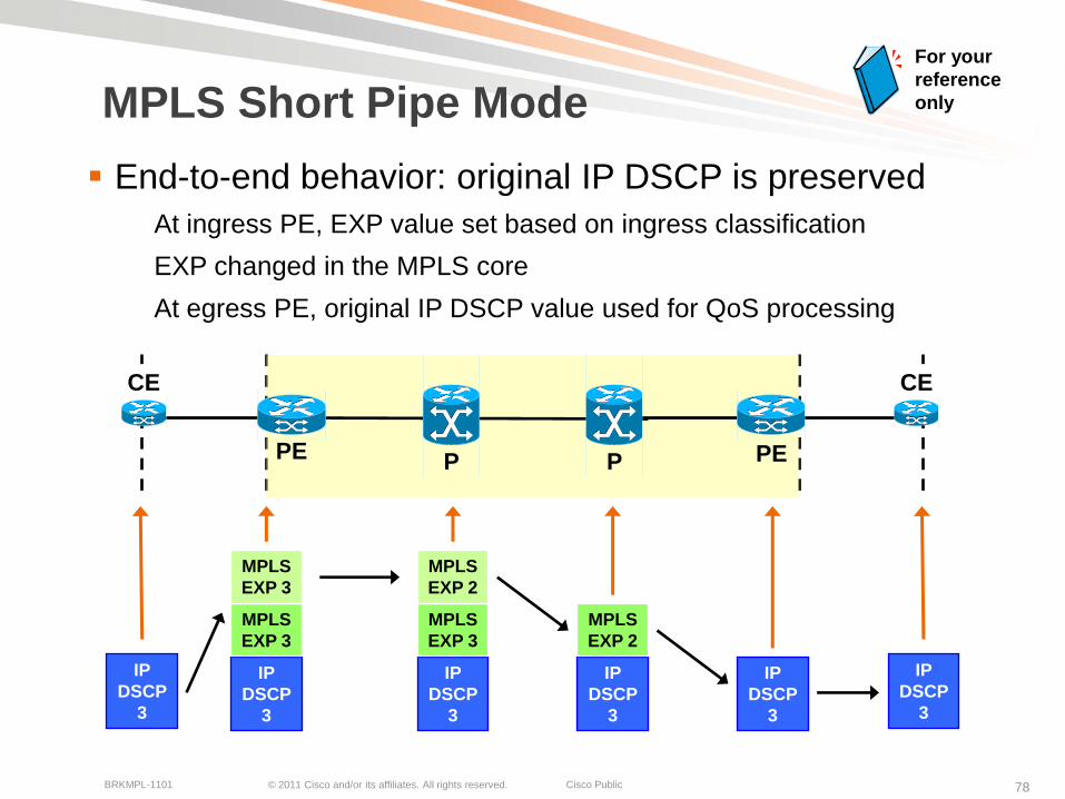
End-to-end behavior: original IP DSCP is preserved
At ingress PE, EXP value set based on ingress classification
EXP changed in the MPLS core
At egress PE, original IP DSCP value used for QoS processing
PPPE PE
CE CE
IP
DSCP
3
IP
DSCP
3
MPLS
EXP 3
MPLS
EXP 3
IP
DSCP
3
IP
DSCP
3
MPLS
EXP 3
MPLS
EXP 2
IP
DSCP
3
MPLS
EXP 2
IP
DSCP
3
For your
reference
only
© 2011 Cisco and/or its affiliates. All rights reserved. Cisco PublicBRKMPL-1101 79
MPLS QoS Summary
MPLS QoS used for MPLS packet-specific marking and classification
Based on EXP bits
Different schemes for mapping between IP (ToS/DSCP) and MPLS packet (EXP) classification
At ingress and egress PE router
MPLS pipe mode mostly used; preserves end-to-end IP QoS
Enables traffic prioritization to guarantee minimal traffic loss and delay for high priority traffic
Useful when packet loss and delay guarantees must be provided for high priority traffic across MPLS network

© 2011 Cisco and/or its affiliates. All rights reserved. Cisco PublicBRKMPL-1101 80
MPLS Traffic EngineeringTechnology Overview and Applications
© 2011 Cisco and/or its affiliates. All rights reserved. Cisco PublicBRKMPL-1101 81
MPLS Technology Framework
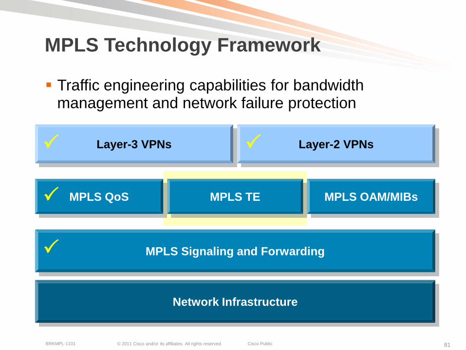
Traffic engineering capabilities for bandwidth management and network failure protection
Network Infrastructure
MPLS Signaling and Forwarding
Layer-3 VPNs Layer-2 VPNs
MPLS QoS MPLS OAM/MIBsMPLS TE
© 2011 Cisco and/or its affiliates. All rights reserved. Cisco PublicBRKMPL-1101 82
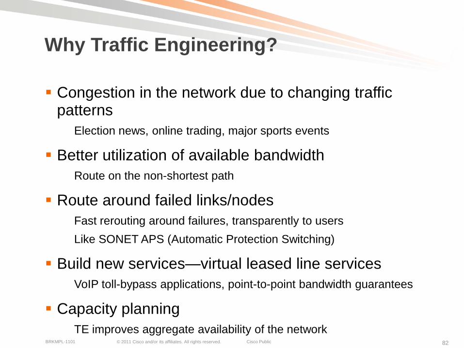
Why Traffic Engineering?
Congestion in the network due to changing traffic patterns
Election news, online trading, major sports events
Better utilization of available bandwidth
Route on the non-shortest path
Route around failed links/nodes
Fast rerouting around failures, transparently to users
Like SONET APS (Automatic Protection Switching)
Build new services—virtual leased line services
VoIP toll-bypass applications, point-to-point bandwidth guarantees
Capacity planning
TE improves aggregate availability of the network

© 2011 Cisco and/or its affiliates. All rights reserved. Cisco PublicBRKMPL-1101 83
Massive (44%) packet loss at router B→router E!
The Problem with Shortest-Path
Changing to A->C->D->E won’t help Router F
Router C Router D
Router A
Router B
OC-3
OC-3
DS3
DS3
DS3OC-3
OC-3
Some links are DS3, some are OC-3
Router A has 40M of traffic for router F, 40M of traffic for router G
Router E
Router G
Node Next-Hop Cost
B B 10
C C 10
D C 20
E B 20
F B 30
G B 30
IP (Mostly) Uses Destination-Based Least-Cost Routing
Alternate Path Under Utilized

© 2011 Cisco and/or its affiliates. All rights reserved. Cisco PublicBRKMPL-1101 84
How MPLS TE Solves the Problem
Router A sees all links
Router A computes paths on properties other than just shortest cost; creation of 2 tunnels
No link oversubscribed!
Router C Router D
OC-3
OC-3
DS3
DS3
DS3OC-3
OC-3
Router F
Router C Router D
Router G
Router A
Router B
Router E
Node Next-Hop Cost
B B 10
C C 10
D C 20
E B 20
F Tunnel 0 30
G Tunnel 1 30

© 2011 Cisco and/or its affiliates. All rights reserved. Cisco PublicBRKMPL-1101 85
How MPLS TE Works
Link information Distribution*
ISIS-TE
OSPF-TE
Path Calculation (CSPF)*
Path Setup (RSVP-TE)
Forwarding Traffic down Tunnel
Auto-route
Static
PBR
CBTS / PBTS
Forwarding Adjacency
Tunnel select
* Optional
IP/MPLS
Head end
Mid-point Tail end
TE LSP

© 2011 Cisco and/or its affiliates. All rights reserved. Cisco PublicBRKMPL-1101 86
Link Information Distribution
Additional link characteristics
Interface address
Neighbor address
Physical bandwidth
Maximum reservable bandwidth
Unreserved bandwidth (at eight priorities)
TE metric
Administrative group (attribute flags)
IS-IS or OSPF flood link information
TE nodes build a topology database
Not required if using off-line path computation
http://www.cisco.com/go/mpls
IP/MPLS
TE Topology database
For your
reference
only

© 2011 Cisco and/or its affiliates. All rights reserved. Cisco PublicBRKMPL-1101 87
Path Calculation
TE nodes can perform constraint-based routing
Constraints and topology database as input to path computation
Shortest-path-first algorithm ignores links not meeting constraints
Tunnel can be signaled once a path is found
Not required if using offline path computation
http://www.cisco.com/go/mpls
IP/MPLS
TE Topology database
53
10
15
10
10
8
10
R1
R8
Link with insufficient bandwidth
Link with sufficient bandwidth
n
n
Find shortest path to R8 with 8Mbps
© 2011 Cisco and/or its affiliates. All rights reserved. Cisco PublicBRKMPL-1101 88
TE LSP Signaling
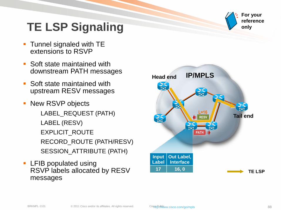
Tunnel signaled with TE extensions to RSVP
Soft state maintained with downstream PATH messages
Soft state maintained with upstream RESV messages
New RSVP objects
LABEL_REQUEST (PATH)
LABEL (RESV)
EXPLICIT_ROUTE
RECORD_ROUTE (PATH/RESV)
SESSION_ATTRIBUTE (PATH)
LFIB populated using RSVP labels allocated by RESV messages
http://www.cisco.com/go/mpls
IP/MPLSHead end
Tail end
TE LSP
PATH
RESV
L=16
Input Label
Out Label, Interface
17 16, 0
For your
reference
only

© 2011 Cisco and/or its affiliates. All rights reserved. Cisco PublicBRKMPL-1101 89
MPLS TE FRR – Link Protection
Primary tunnel: A → B → D → E
Backup tunnel: B → C → D (preprovisioned)
Recovery = ~ 50 ms
Router D
Router C
Router A Router B Router E
Router YRouter X
*Actual Time Varies—Well Below 50 ms in Lab Tests, Can Also Be Higher
© 2011 Cisco and/or its affiliates. All rights reserved. Cisco PublicBRKMPL-1101 90
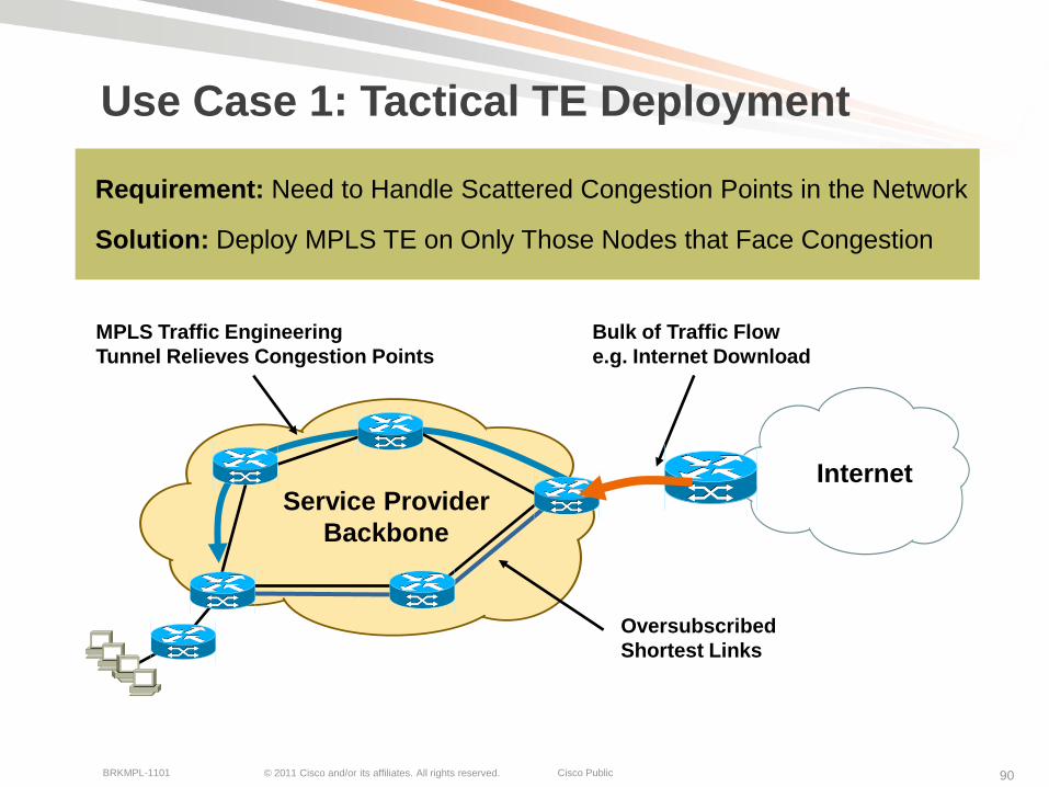
Use Case 1: Tactical TE Deployment
Requirement: Need to Handle Scattered Congestion Points in the Network
Solution: Deploy MPLS TE on Only Those Nodes that Face Congestion
InternetService Provider
Backbone
Bulk of Traffic Flow
e.g. Internet Download
Oversubscribed
Shortest Links
MPLS Traffic Engineering
Tunnel Relieves Congestion Points

© 2011 Cisco and/or its affiliates. All rights reserved. Cisco PublicBRKMPL-1101 91
Use Case 2: 1-Hop Tunnel Deployment
Requirement: Need Protection Only — Minimize Packet Loss of Bandwidth in the Core
Solution: Deploy MPLS Fast Reroute for Less than 50ms Failover Time with 1-Hop Primary TE Tunnels and Backup Tunnel for Each
Service Provider
Backbone
VPN Site A VPN Site BPrimary 1-Hop TE Tunnel
Backup Tunnel
Physical Links

© 2011 Cisco and/or its affiliates. All rights reserved. Cisco PublicBRKMPL-1101 92
MPLS TE Summary
MPLS TE can be used to implement traffic engineering to enable enhanced network availability, utilization, and performance
Enhanced network availability can be implemented via MPLS TE Fast Re-Route (FRR)
Link, node, and path protection
Automatically route around failed links/nodes; like SONET APS
Better network bandwidth utilization can be implemented via creation of MPLS TE tunnels using explicit routes
Route on the non-shortest path
MPLS TE can be used for capacity planning by creation of bandwidth-specific tunnels with explicit paths through the network
Bandwidth management across links and end-to-end paths

© 2011 Cisco and/or its affiliates. All rights reserved. Cisco PublicBRKMPL-1101 93
MPLS ManagementTechnology Overview and Applications

© 2011 Cisco and/or its affiliates. All rights reserved. Cisco PublicBRKMPL-1101 94
MPLS Technology Framework
MPLS management using SNMP MPLS MIB and MPLS OAM capabilities
Network Infrastructure
MPLS Signaling and Forwarding
Layer-3 VPNs Layer-2 VPNs
MPLS QoS MPLS OAM/MIBsMPLS TE

© 2011 Cisco and/or its affiliates. All rights reserved. Cisco PublicBRKMPL-1101 95
What’s Needed for MPLS management?
What’s needed beyond the basic MPLS CLI?
CLI used for basic configuration and trouble shooting (show commands)
Traditional management tools:
MIBs to provide management information for SNMP management applications (e.g., HPOV)
MIB counters, Trap notifications, etc.
New management tools:
MPLS OAM -> for reactive trouble shooting
Ping and trace capabilities of MPLS label switched paths
Automated MPLS OAM -> for proactive trouble shooting
Automated LSP ping/trace via Auto IP SLA
© 2011 Cisco and/or its affiliates. All rights reserved. Cisco PublicBRKMPL-1101 96
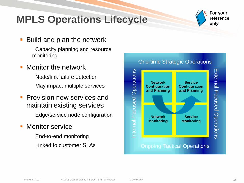
MPLS Operations Lifecycle
Build and plan the network
Capacity planning and resource monitoring
Monitor the network
Node/link failure detection
May impact multiple services
Provision new services and maintain existing services
Edge/service node configuration
Monitor service
End-to-end monitoring
Linked to customer SLAs
For your
reference
only
Network Configuration and Planning
Service Configuration and Planning
Network Monitoring
Service Monitoring
Inte
rna
l-F
ocu
se
d O
pe
ratio
ns
Exte
rna
l-Fo
cu
se
d O
pe
ratio
ns
One-time Strategic Operations
Ongoing Tactical Operations
© 2011 Cisco and/or its affiliates. All rights reserved. Cisco PublicBRKMPL-1101 97
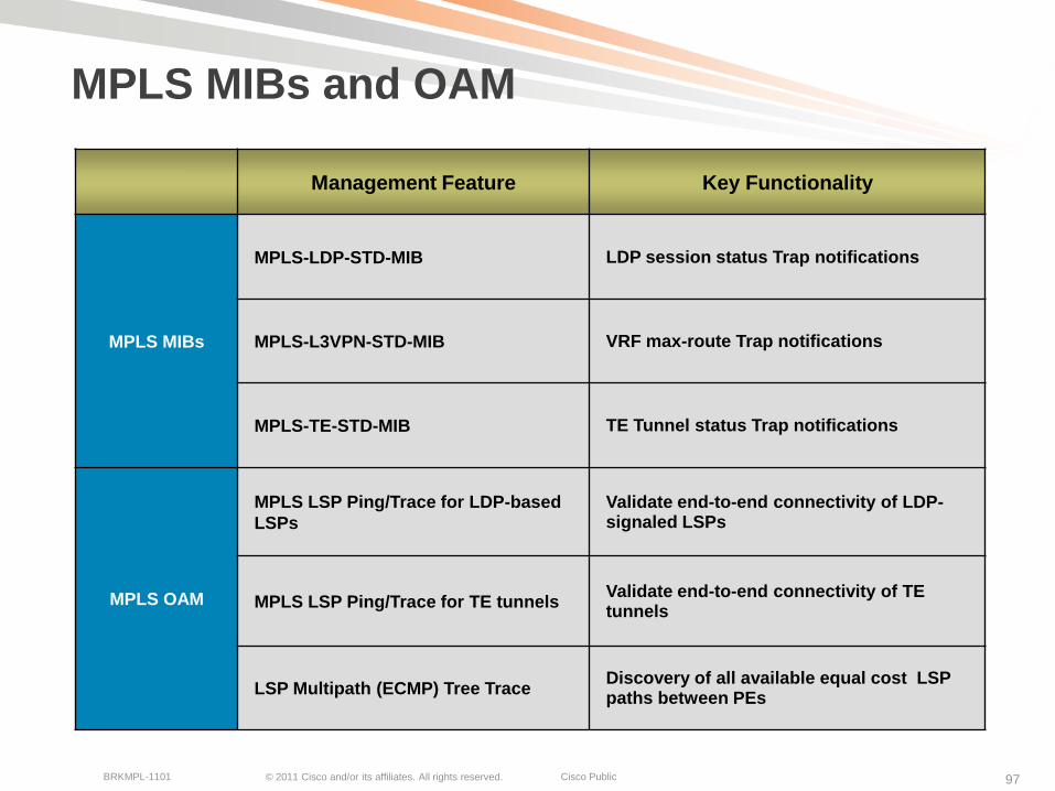
MPLS MIBs and OAM
Management Feature Key Functionality
MPLS MIBs
MPLS-LDP-STD-MIB LDP session status Trap notifications
MPLS-L3VPN-STD-MIB VRF max-route Trap notifications
MPLS-TE-STD-MIB TE Tunnel status Trap notifications
MPLS OAM
MPLS LSP Ping/Trace for LDP-based
LSPs
Validate end-to-end connectivity of LDP-signaled LSPs
MPLS LSP Ping/Trace for TE tunnelsValidate end-to-end connectivity of TE tunnels
LSP Multipath (ECMP) Tree TraceDiscovery of all available equal cost LSP paths between PEs
© 2011 Cisco and/or its affiliates. All rights reserved. Cisco PublicBRKMPL-1101 98
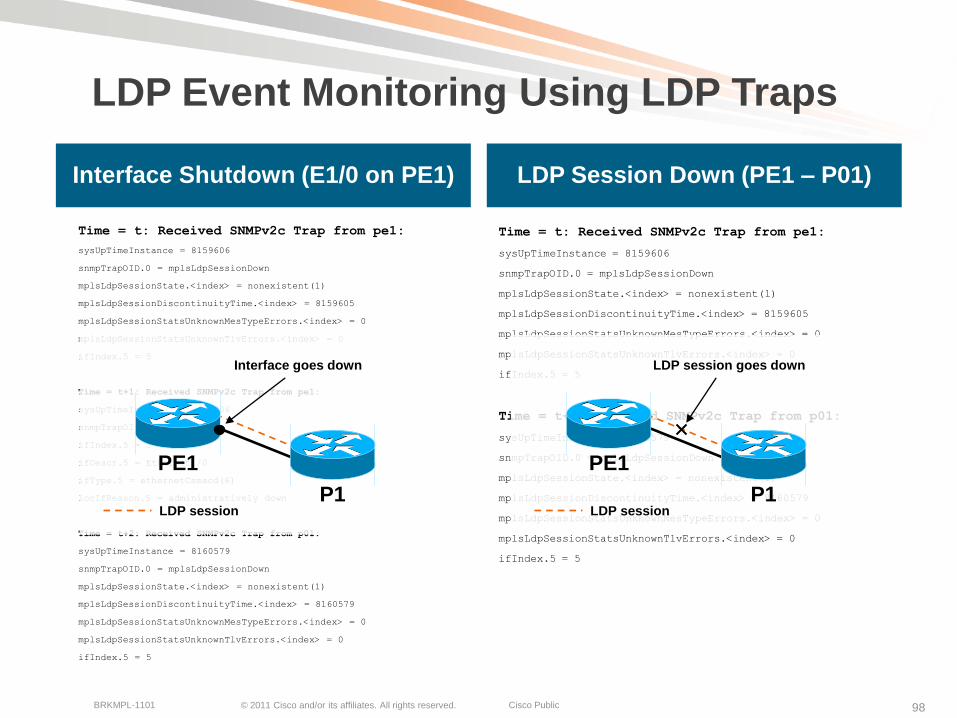
LDP Event Monitoring Using LDP Traps
Time = t: Received SNMPv2c Trap from pe1:
sysUpTimeInstance = 8159606
snmpTrapOID.0 = mplsLdpSessionDown
mplsLdpSessionState.<index> = nonexistent(1)
mplsLdpSessionDiscontinuityTime.<index> = 8159605
mplsLdpSessionStatsUnknownMesTypeErrors.<index> = 0
mplsLdpSessionStatsUnknownTlvErrors.<index> = 0
ifIndex.5 = 5
Time = t+1: Received SNMPv2c Trap from pe1:
sysUpTimeInstance = 8159906
snmpTrapOID.0 = linkDown
ifIndex.5 = 5
ifDescr.5 = Ethernet1/0
ifType.5 = ethernetCsmacd(6)
locIfReason.5 = administratively down
Time = t+2: Received SNMPv2c Trap from p01:
sysUpTimeInstance = 8160579
snmpTrapOID.0 = mplsLdpSessionDown
mplsLdpSessionState.<index> = nonexistent(1)
mplsLdpSessionDiscontinuityTime.<index> = 8160579
mplsLdpSessionStatsUnknownMesTypeErrors.<index> = 0
mplsLdpSessionStatsUnknownTlvErrors.<index> = 0
ifIndex.5 = 5
Time = t: Received SNMPv2c Trap from pe1:
sysUpTimeInstance = 8159606
snmpTrapOID.0 = mplsLdpSessionDown
mplsLdpSessionState.<index> = nonexistent(1)
mplsLdpSessionDiscontinuityTime.<index> = 8159605
mplsLdpSessionStatsUnknownMesTypeErrors.<index> = 0
mplsLdpSessionStatsUnknownTlvErrors.<index> = 0
ifIndex.5 = 5
Time = t+1: Received SNMPv2c Trap from p01:
sysUpTimeInstance = 8160579
snmpTrapOID.0 = mplsLdpSessionDown
mplsLdpSessionState.<index> = nonexistent(1)
mplsLdpSessionDiscontinuityTime.<index> = 8160579
mplsLdpSessionStatsUnknownMesTypeErrors.<index> = 0
mplsLdpSessionStatsUnknownTlvErrors.<index> = 0
ifIndex.5 = 5
Interface Shutdown (E1/0 on PE1) LDP Session Down (PE1 – P01)
PE1
P1LDP session
Interface goes down
PE1
P1LDP session
LDP session goes down
© 2011 Cisco and/or its affiliates. All rights reserved. Cisco PublicBRKMPL-1101 99
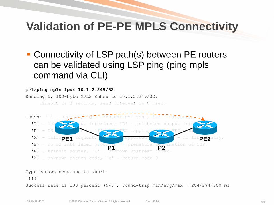
Validation of PE-PE MPLS Connectivity
Connectivity of LSP path(s) between PE routers can be validated using LSP ping (ping mpls command via CLI)
pe1>ping mpls ipv4 10.1.2.249/32
Sending 5, 100-byte MPLS Echos to 10.1.2.249/32,
timeout is 2 seconds, send interval is 0 msec:
Codes: '!' - success, 'Q' - request not sent, '.' - timeout,
'L' - labeled output interface, 'B' - unlabeled output interface,
'D' - DS Map mismatch, 'F' - no FEC mapping, 'f' - FEC mismatch,
'M' - malformed request, 'm' - unsupported tlvs, 'N' - no label entry,
'P' - no rx intf label prot, 'p' - premature termination of LSP,
'R' - transit router, 'I' - unknown upstream index,
'X' - unknown return code, 'x' - return code 0
Type escape sequence to abort.
!!!!!
Success rate is 100 percent (5/5), round-trip min/avg/max = 284/294/300 ms
PE1
P1 P2
PE2

© 2011 Cisco and/or its affiliates. All rights reserved. Cisco PublicBRKMPL-1101 100
Automated MPLS OAM
Automatic MPLS OAM probes between PE routersAutomatic discovery of PE targets via BGP next-hop discovery
Automatic discovery of all available LSP paths for PE targets via LSP multi-path trace
Scheduled LSP pings to verify LSP path connectivity
3 consecutive LSP ping failures result in SNMP Trap notification
PE3
PE2
P2P1
PE1
PE1 - MPLS OAM Probe
PE2 - MPLS OAM Probe
PE3 - MPLS OAM Probe
© 2011 Cisco and/or its affiliates. All rights reserved. Cisco PublicBRKMPL-1101 101
MPLS Management Summary
MPLS management operations include MPLS node and service configuration, and monitoring
In addition to CLI, SNMP MIBs and OAM capabilities are available for MPLS management
MPLS MIBs provide LDP, VPN, and TE management information, which can be collected by SNMP tools
MIB counters, Trap notifications
Advanced MPLS management capabilities can be implemented via MPLS OAM
LSP path discovery and connectivity validation
Proactive monitoring via automated MPLS OAM

© 2011 Cisco and/or its affiliates. All rights reserved. Cisco PublicBRKMPL-1101 102
SummaryFinal Notes and Wrap Up
© 2011 Cisco and/or its affiliates. All rights reserved. Cisco PublicBRKMPL-1101 103
Summary and Key Takeaways
It’s all about labels …
Label-based forwarding and IP protocol extensions for label exchange
Best of both worlds … L2-type forwarding and L3 control plane
Key application of MPLS is to implement VPN services
Secure and scalable layer 2 and 3 VPN connectivity
MPLS supports advanced traffic engineering capabilities
QoS, bandwidth control, and failure protection
MPLS is a mature technology with widespread deployments
Both SP and enterprise networks
Two types of MPLS users
Indirect (Subscriber): MPLS used as transport for subscribed service
Direct (DIY): MPLS implemented in (own) SP or enterprise network

© 2011 Cisco and/or its affiliates. All rights reserved. Cisco PublicBRKMPL-1101 104
Consider MPLS When …
There’s a need for network segmentation
Segmented connectivity for specific locations, users, applications, etc.
Full-mesh and hub-and-spoke connectivity
There’s a need for network realignment/migration
Consolidation of (multiple) legacy networks
Staged network consolidation after company merger/acquisition
There’s a need for optimized network availability and performance
Node/link protection, pro-active connectivity validation
Bandwidth traffic engineering and QoS traffic prioritization
© 2011 Cisco and/or its affiliates. All rights reserved. Cisco PublicBRKMPL-1101 105
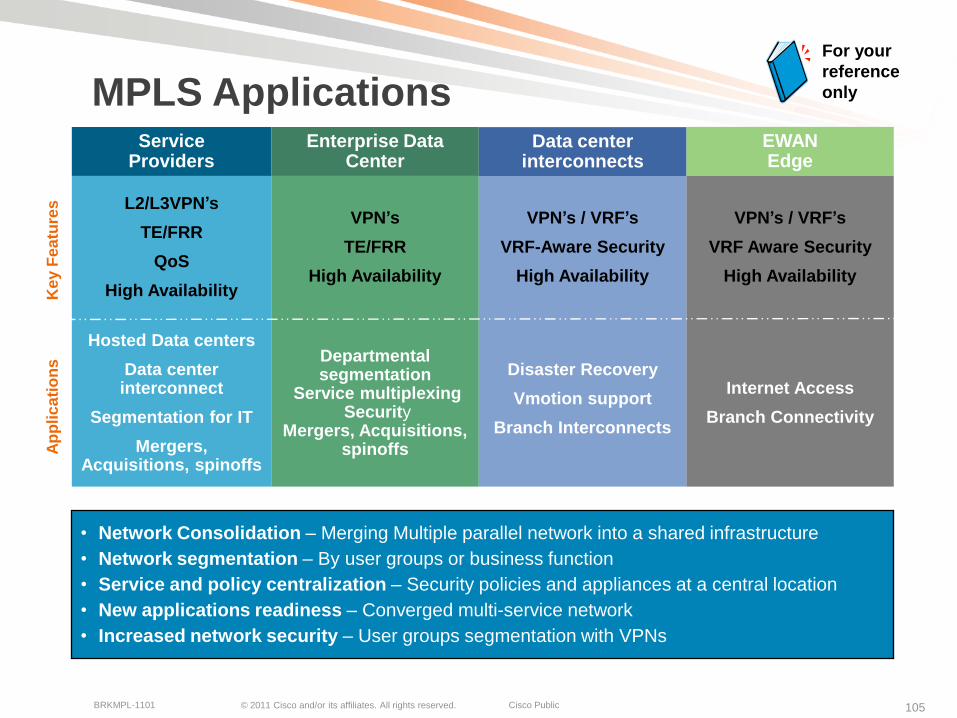
MPLS Applications
•••••
EWAN Edge
Service Providers
Enterprise Data Center
Data center interconnects
L2/L3VPN’s
TE/FRR
QoS
High Availability
VPN’s / VRF’s
VRF-Aware Security
High Availability
Hosted Data centers
Data center interconnect
Segmentation for IT
Mergers, Acquisitions, spinoffs
Ap
plic
ati
on
sK
ey F
ea
ture
s
Departmental segmentation
Service multiplexingSecurity
Mergers, Acquisitions, spinoffs
Disaster Recovery
Vmotion support
Branch Interconnects
Internet Access
Branch Connectivity
VPN’s / VRF’s
VRF Aware Security
High Availability
VPN’s
TE/FRR
High Availability
• Network Consolidation – Merging Multiple parallel network into a shared infrastructure
• Network segmentation – By user groups or business function
• Service and policy centralization – Security policies and appliances at a central location
• New applications readiness – Converged multi-service network
• Increased network security – User groups segmentation with VPNs
For your
reference
only

© 2011 Cisco and/or its affiliates. All rights reserved. Cisco PublicBRKMPL-1101 106
Q&A
© 2011 Cisco and/or its affiliates. All rights reserved. Cisco PublicBRKMPL-1101 107
Cisco Live 2011 MPLS Sessions
More MPLS topics covered in following sessions:
BRKRST-2102 Deploying IP/MPLS VPNs
BRKRST-2104 Deploying MPLS Traffic Engineering
BRKRST-2105 Inter-AS MPLS Solutions
BRKRST-3101 Advanced Topics and Future Directions in MPLS
© 2011 Cisco and/or its affiliates. All rights reserved. Cisco PublicBRKMPL-1101 108
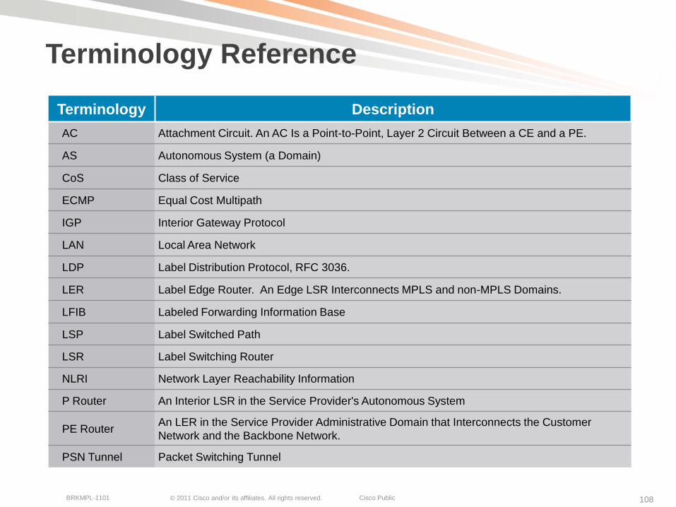
Terminology Reference
Terminology Description
AC Attachment Circuit. An AC Is a Point-to-Point, Layer 2 Circuit Between a CE and a PE.
AS Autonomous System (a Domain)
CoS Class of Service
ECMP Equal Cost Multipath
IGP Interior Gateway Protocol
LAN Local Area Network
LDP Label Distribution Protocol, RFC 3036.
LER Label Edge Router. An Edge LSR Interconnects MPLS and non-MPLS Domains.
LFIB Labeled Forwarding Information Base
LSP Label Switched Path
LSR Label Switching Router
NLRI Network Layer Reachability Information
P Router An Interior LSR in the Service Provider's Autonomous System
PE RouterAn LER in the Service Provider Administrative Domain that Interconnects the Customer
Network and the Backbone Network.
PSN Tunnel Packet Switching Tunnel

© 2011 Cisco and/or its affiliates. All rights reserved. Cisco PublicBRKMPL-1101 109
Terminology Reference
Terminology Description
Pseudo-WireA Pseudo-Wire Is a Bidirectional ―Tunnel" Between Two Features on a
Switching Path.
PWE3 Pseudo-Wire End-to-End Emulation
QoS Quality of Service
RD Route Distinguisher
RIB Routing Information Base
RR Route Reflector
RT Route Target
RSVP-TE Resource Reservation Protocol based Traffic Engineering
VPN Virtual Private Network
VFI Virtual Forwarding Instance
VLAN Virtual Local Area Network
VPLS Virtual Private LAN Service
VPWS Virtual Private WAN Service
VRF Virtual Route Forwarding Instance
VSI Virtual Switching Instance

© 2011 Cisco and/or its affiliates. All rights reserved. Cisco PublicBRKMPL-1101 110
Further Reading
http://www.cisco.com/go/mpls
http://www.ciscopress.com
MPLS and VPN Architectures—Jim Guichard, Ivan Papelnjak—Cisco Press®
Traffic Engineering with MPLS—Eric Osborne, Ajay Simha—Cisco Press
Layer 2 VPN Architectures—Wei Luo, Carlos Pignataro, Dmitry Bokotey, Anthony Chan—Cisco Press
MPLS QoS—Santiago Alvarez-Cisco Press
© 2011 Cisco and/or its affiliates. All rights reserved. Cisco PublicBRKMPL-1101 111
Complete Your Online Session Evaluation
Receive 25 Cisco Preferred Access points for each session evaluation you complete.
Give us your feedback and you could win fabulous prizes. Points are calculated on a daily basis. Winners will be notified by email after July 22nd.
Complete your session evaluation online now (open a browser through our wireless network to access our portal) or visit one of the Internet stations throughout the Convention Center.
Don’t forget to activate your Cisco Live and Networkers Virtual account for access to all session materials, communities, and on-demand and live activities throughout the year. Activate your account at any internet station or visit www.ciscolivevirtual.com.

© 2011 Cisco and/or its affiliates. All rights reserved. Cisco PublicBRKMPL-1101 112
Visit the Cisco Store for Related Titles
http://theciscostores.com
© 2011 Cisco and/or its affiliates. All rights reserved. Cisco PublicBRKMPL-1101 113
© 2011 Cisco and/or its affiliates. All rights reserved. Cisco PublicBRKMPL-1101 114
Thank you.


![MPPP Support [Cisco IOS XE 3S] - Cisco...MPLS Basic MPLS Configuration Guide, Cisco IOS XE Release 3S 3 MPLS Multilink PPP Support MPLS Quality of Service Features Supported for Multilink](https://static.documents.pub/doc/80x56/613a24070051793c8c00dfef/mppp-support-cisco-ios-xe-3s-cisco-mpls-basic-mpls-configuration-guide.jpg)


