
Introduction to Telephony
PacNOG6 VoIP WorkshopNadi, Fiji. November 2009
Jonny Martin - [email protected]
Analogue Telephony
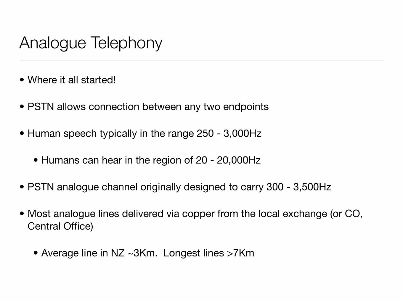
• Where it all started!
• PSTN allows connection between any two endpoints
• Human speech typically in the range 250 - 3,000Hz
• Humans can hear in the region of 20 - 20,000Hz
• PSTN analogue channel originally designed to carry 300 - 3,500Hz
• Most analogue lines delivered via copper from the local exchange (or CO, Central Office)
• Average line in NZ ~3Km. Longest lines >7Km
Analogue Telephony
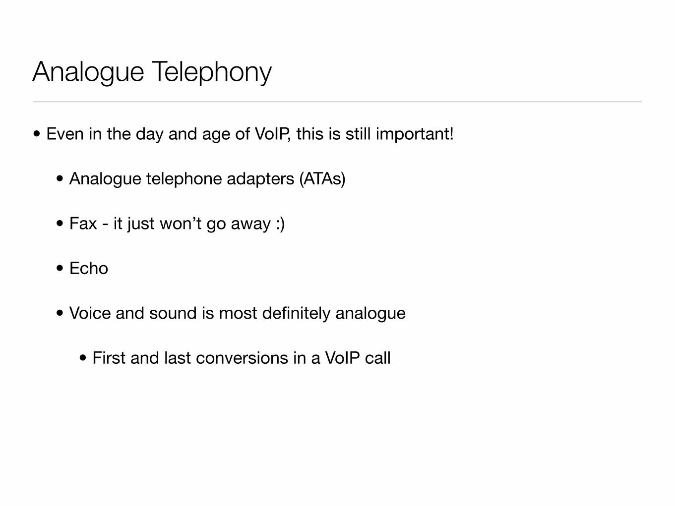
• Even in the day and age of VoIP, this is still important!
• Analogue telephone adapters (ATAs)
• Fax - it just won’t go away :)
• Echo
• Voice and sound is most definitely analogue
• First and last conversions in a VoIP call
The Analogue Telephone
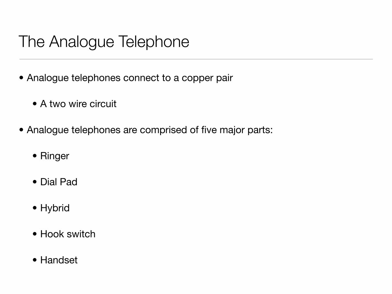
• Analogue telephones connect to a copper pair
• A two wire circuit
• Analogue telephones are comprised of five major parts:
• Ringer
• Dial Pad
• Hybrid
• Hook switch
• Handset
Ringer
• The exchange provides DC (~48vDC) to power the phone
• Exchange = big centralised UPS
• Exchange provides a burst of AC (~80vAC) to ring the phone’s bell
• Originally a mechanical bell, these days an electronic buzzer
• These days phone have a Ringer Equivalence Number (REN)
• Exchange can power up to a sum of 5 RENs
• Phones these days typically < 0.5 REN
• ATAs have same limitation
Dial Pad
• Telephones need to signal back to the exchange
• Originally done with a rotary dialler making and breaking the copper loop
• Pulse Dial, still typically supported by exchanges and some VoIP kit
• All done with audio tones now
• Dual Tone Multi Frequency (DTMF)
• Telephone handsets a matrix of switches
• One tone per column, one per row
• Each switch generates two tones, hence Dual Tone
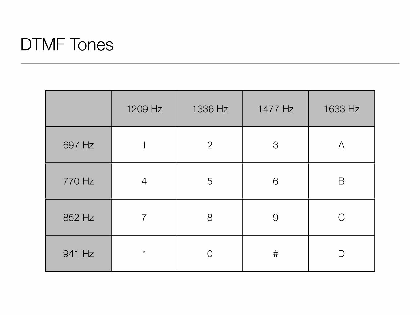
DTMF Tones
1209 Hz 1336 Hz 1477 Hz 1633 Hz
697 Hz
770 Hz
852 Hz
941 Hz
1 2 3 A
4 5 6 B
7 8 9 C
* 0 # D
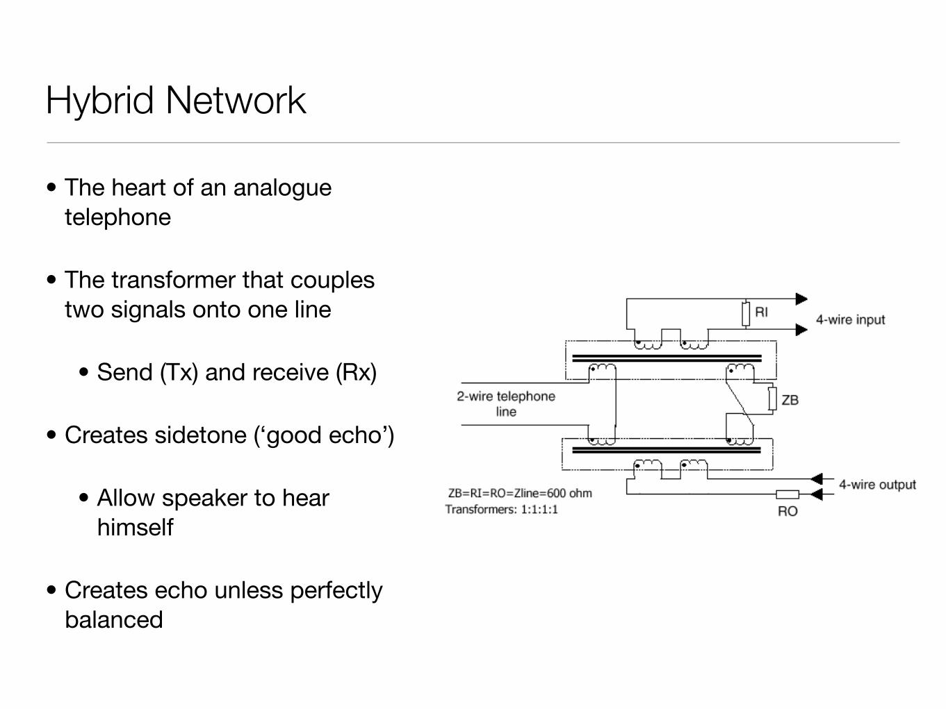
Hybrid Network
• The heart of an analogue telephone
• The transformer that couples two signals onto one line
• Send (Tx) and receive (Rx)
• Creates sidetone (‘good echo’)
• Allow speaker to hear himself
• Creates echo unless perfectly balanced
Technical Tips.
Hybrid Transformers
The older telecommunication circuits used for remote control of radio base stations were 2 wire circuits, and probably DC circuits (no inline amplification).
In recent times, say the last ten years, private wire circuits tend to be presented to the user as a 4 wire circuit. If you are about to order a circuit for control of a remote base
station, then do yourself a favour and make sure it is presented as a 4 wire line.
However, if you already have a 2 wire line and need to attach one of our controllers, or controller base station combinations, then you will need to convert from 4 wire to 2 wire at the control end and back to 4 wire at the base station.
If the base station is line equipped, then it probably has a hybrid built in to cope with
2 to 4 wire conversion. When we speak of 4 wire working we mean 2 wires are used for incoming audio, and
2 wires are used for outgoing audio. Where signalling or tone detection is involved in the system, it is important that coupling between the different pairs (Cross talk) is
kept to a minimum, and should be at least –25db relative to tone detection thresholds. The hybrid itself is a simple device constructed from two transformers interconnected
in such a way as to cause a 180o phase shift between the 4 wire source pairs. In other words, the audio you send up the line is not coupled to nor reflected back along the
adjacent pairs. If this were to become the case, then all sorts of system problems would become apparent. When the hybrid is “matched” to the impedance of the line, the reflective nature of the coupling is at a minimum.
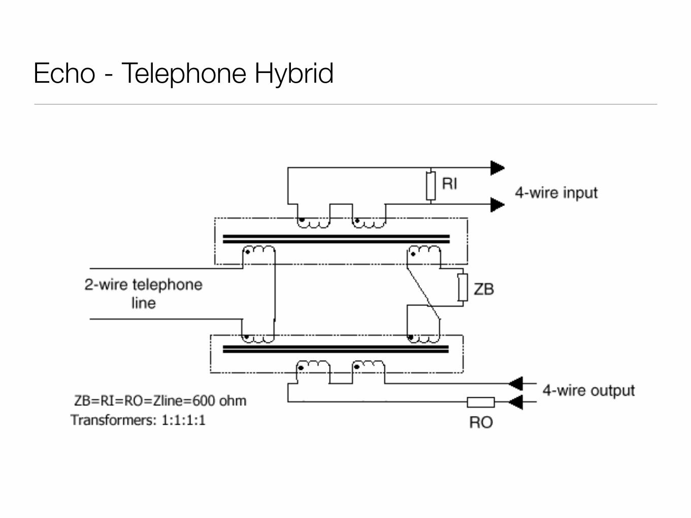
Here is a diagram of a basic hybrid configuration
In the above diagram R0 and R1 represent the telephone line impedance, and ZB should be of a value which matches the telephone line impedance. In reality, ZB will
be variable because the impedance of each telephone line will differ slightly.
It should however be noted that the unit will not adjust to balance if any part of the hybrid is left un-terminated.
Hook Switch
• Telephone uses it to signal state to the exchange
• On Hook, closes the copper loop
• Phone idles, waiting for incoming ring
• Off Hook, breaks the copper loop
• Requests dial tone from the exchange, and then allows audio to pass
• Also used to signal ‘advanced’ features, e.g. call waiting
• Hook Flash - a timed closure of the hook switch, typically ~300ms
This is the Title of the Book, eMatter EditionCopyright © 2005 O’Reilly & Associates, Inc. All rights reserved.
122 | Chapter 7: Understanding Telephony
Handset. The handset is composed of the transmitter and receiver. It performs theconversion between the sound energy humans use and the electrical energy the tele-phone network uses.
Tip and RingIn an analog telephone circuit, there are two wires. In North America, these wires arereferred to as Tip and Ring.* This terminology comes from the days when telephonecalls were connected by live operators sitting at cord boards. The plugs they usedhad two contacts, one located at the tip of the plug and the other connected to thering around the middle (Figure 7-1).
The Tip lead is the positive polarity wire. In North America, this wire is typicallygreen and provides the return path. The Ring wire is the negative polarity wire. InNorth America, this wire is normally red. When your telephone is on-hook, this wirewill have a potential of –48V DC with respect to Tip. Off-hook, this voltage drops toroughly –7V DC.
Digital TelephonyAnalog telephony is almost dead.
In the PSTN, the famous Last Mile is the final remaining piece of the telephone net-work still using technology pioneered well over a hundred years ago.†
One of the primary challenges when transmitting analog signals is that all sorts ofthings can interfere with those signals, causing low volume, static, and all manner ofother undesired effects. Instead of trying to preserve an analog waveform over dis-tances that may span thousands of miles, why not simply measure the characteristics
* They may have other names elsewhere in the world (such as “A” and “B”).
Figure 7-1. Tip and Ring
† “The Last Mile” is a term that was originally used to describe the only portion of the PSTN that had not beenconverted to fiber optics: the connection between the central office and the customer. The Last Mile is morethan that, however, as it also has significance as a valuable asset of the traditional phone companies—theyown a connection into your home. The Last Mile is becoming more and more difficult to describe in techni-cal terms, as there are now so many ways to connect the network to the customer. As a thing of strategicvalue to telecom, cable, and other utilities, its importance is obvious.
Ring Tip
,ch07.21568 Page 122 Wednesday, August 31, 2005 4:57 PM
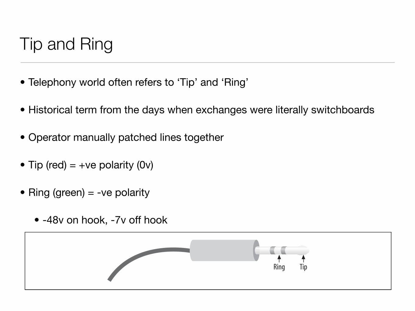
Tip and Ring
• Telephony world often refers to ‘Tip’ and ‘Ring’
• Historical term from the days when exchanges were literally switchboards
• Operator manually patched lines together
• Tip (red) = +ve polarity (0v)
• Ring (green) = -ve polarity
• -48v on hook, -7v off hook
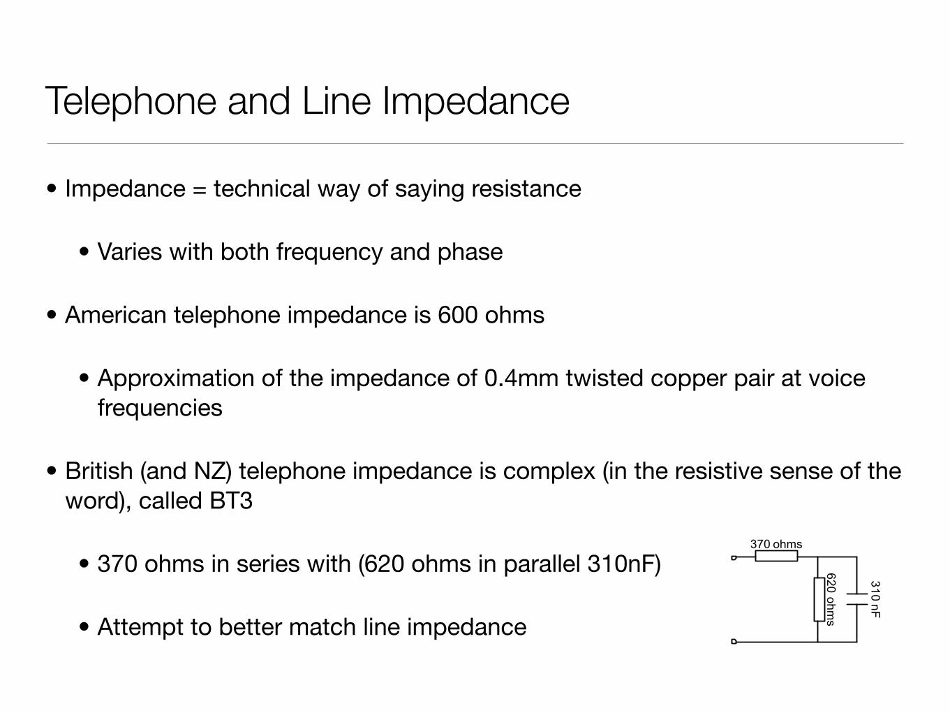
Telephone and Line Impedance
• Impedance = technical way of saying resistance
• Varies with both frequency and phase
• American telephone impedance is 600 ohms
• Approximation of the impedance of 0.4mm twisted copper pair at voice frequencies
• British (and NZ) telephone impedance is complex (in the resistive sense of the word), called BT3
• 370 ohms in series with (620 ohms in parallel 310nF)
• Attempt to better match line impedance
PTC 280: 2001
DRAFT FOR PUBLIC COMMENT
A.2
A1.3 ATU-R simulationWhere applicable, the ATU-R shall be simulated by 28 nF + 39 ! and
measurements repeated with an open circuit in place of ATU-R, for voicefrequencies. At ADSL frequencies, ATU-R is simulated by 28 nF + (470 µH //
100 !). The series resistance of the inductor is not critical, but its design must
be consistent with valid operation up to 1100 kHz.
BT3 Reference Impedance370 ohms
62
0 o
hm
s
31
0 n
F
N Reference Impedance
60
0 o
hm
s
620 ohms
35
nF
ZON – Simulated on hook impedance of aphone. 1
Mohm
ZATU-R, VF – Simulated impedance of ATU-R,valid for Voice Frequencies (0 – 4 kHz).
56 nF
56 nF
39 o
hm
s
ZATU-R, HF – Simulated impedance of ATU-R
for High Frequencies (25kHz – 10MHz).
470 u
H
56 nF
56 nF
10
0 o
hm
s
Figure 2: Simulated and reference impedances.
A1.4 Test Line
(1) The access line used for tests is 0.2, 1.5 and 3.6 km of 0.4 mm PEFUTcable.
(2) Consideration will be given to approval of equivalent artificial cable havingconstants of 274 !/km and 49.2 nF/km for VF tests. Line sections shall not
Echo
• VoIP does not cause Echo!
• Hybrids cause echo
• Echo becomes apparent as latency increases
• VoIP creates higher latency than circuit switched circuits
• Hybrids must be balanced to the line to effect maximum power transfer and minimal signal reflection
• Reflection back down the line = echo
• Reflection back towards the handset = sidetone
Technical Tips.
Hybrid Transformers
The older telecommunication circuits used for remote control of radio base stations were 2 wire circuits, and probably DC circuits (no inline amplification).
In recent times, say the last ten years, private wire circuits tend to be presented to the user as a 4 wire circuit. If you are about to order a circuit for control of a remote base
station, then do yourself a favour and make sure it is presented as a 4 wire line.
However, if you already have a 2 wire line and need to attach one of our controllers, or controller base station combinations, then you will need to convert from 4 wire to 2 wire at the control end and back to 4 wire at the base station.
If the base station is line equipped, then it probably has a hybrid built in to cope with
2 to 4 wire conversion. When we speak of 4 wire working we mean 2 wires are used for incoming audio, and
2 wires are used for outgoing audio. Where signalling or tone detection is involved in the system, it is important that coupling between the different pairs (Cross talk) is
kept to a minimum, and should be at least –25db relative to tone detection thresholds. The hybrid itself is a simple device constructed from two transformers interconnected
in such a way as to cause a 180o phase shift between the 4 wire source pairs. In other words, the audio you send up the line is not coupled to nor reflected back along the
adjacent pairs. If this were to become the case, then all sorts of system problems would become apparent. When the hybrid is “matched” to the impedance of the line, the reflective nature of the coupling is at a minimum.
Here is a diagram of a basic hybrid configuration
In the above diagram R0 and R1 represent the telephone line impedance, and ZB should be of a value which matches the telephone line impedance. In reality, ZB will
be variable because the impedance of each telephone line will differ slightly.
It should however be noted that the unit will not adjust to balance if any part of the hybrid is left un-terminated.
Echo - Telephone Hybrid
Echo
• Sidetone is used to let the user know that the phone ‘is working’
• It’s somewhat unnatural to not her oneself
• Too much sidetone and you can only hear yourself
• Too little and it appears the line is dead
• Echo is present on most lines
• When latency is low (< 20ms or so) the far end perceives it as sidetone
Acoustic Echo
• Caused by the output of the handset’s speaker entering the microphone
• Due to the speaker volume being too loud or microphone sensitivity too loud
• Very bad with softphones when not using a headset
• Or flimsy handset construction (acoustic coupling through the handset itself)
• The telephone handset design hasn’t changed much over the years as it is a very good one!
• Indistinguishable to the far end from echo caused by the local hybrid
Reducing Echo
• There are only four ways to reduce echo
• Remove the two wire (analogue) portion of the call
• Balance the analogue portion of the call better
• Hard to do even if you do have access to the endpoint(s)
• Reduce the latency
• Often impossible, e.g. long distance calls
• Cancel the echo
Echo Cancellers
• Measure signal on the line, predict the echo, and create a signal to cancel it
• Echo cancellers are configured for a ‘tail’ length - the maximum latency of an echo which it can possibly cancel
• Takes time to converge to an echo cancelled state, dependant on the tail length of the canceller
• Echo cancellers aren’t perfect, so best to prevent echo in the first place
• Popular misconception that software based echo cancellation is bad.
• Hardware echo cancellers have very good, often patented algorithms
• No really good open source software implementations (yet...)
• Software echo cancellation is not bad - if you have a good algorithm!
Digital Telephony
• Telephony moved digital for the same reason everything else did
• Voice turned to a digital signal using Pulse Code Modulation (PCM)
• Sample signal in time
• Two important factors:
• Number of samples per second (highest frequency is half of the sample rate - Nyquist’s Theorem)
• Number of bits used to encode signal
• Tradeoff between quality and bandwidth - standard is 8bits at 8kHz sampling
This is the Title of the Book, eMatter EditionCopyright © 2005 O’Reilly & Associates, Inc. All rights reserved.
The Digital Circuit-Switched Telephone Network | 131
Circuit TypesIn the PSTN, there are many different sizes of circuits serving the various needs of thenetwork. Between the central office and a subscriber, one or more analog circuits, or afew dozen channels delivered over a digital circuit, generally suffice. Between PSTNoffices (and with larger customers), fiber-optic circuits are generally used.
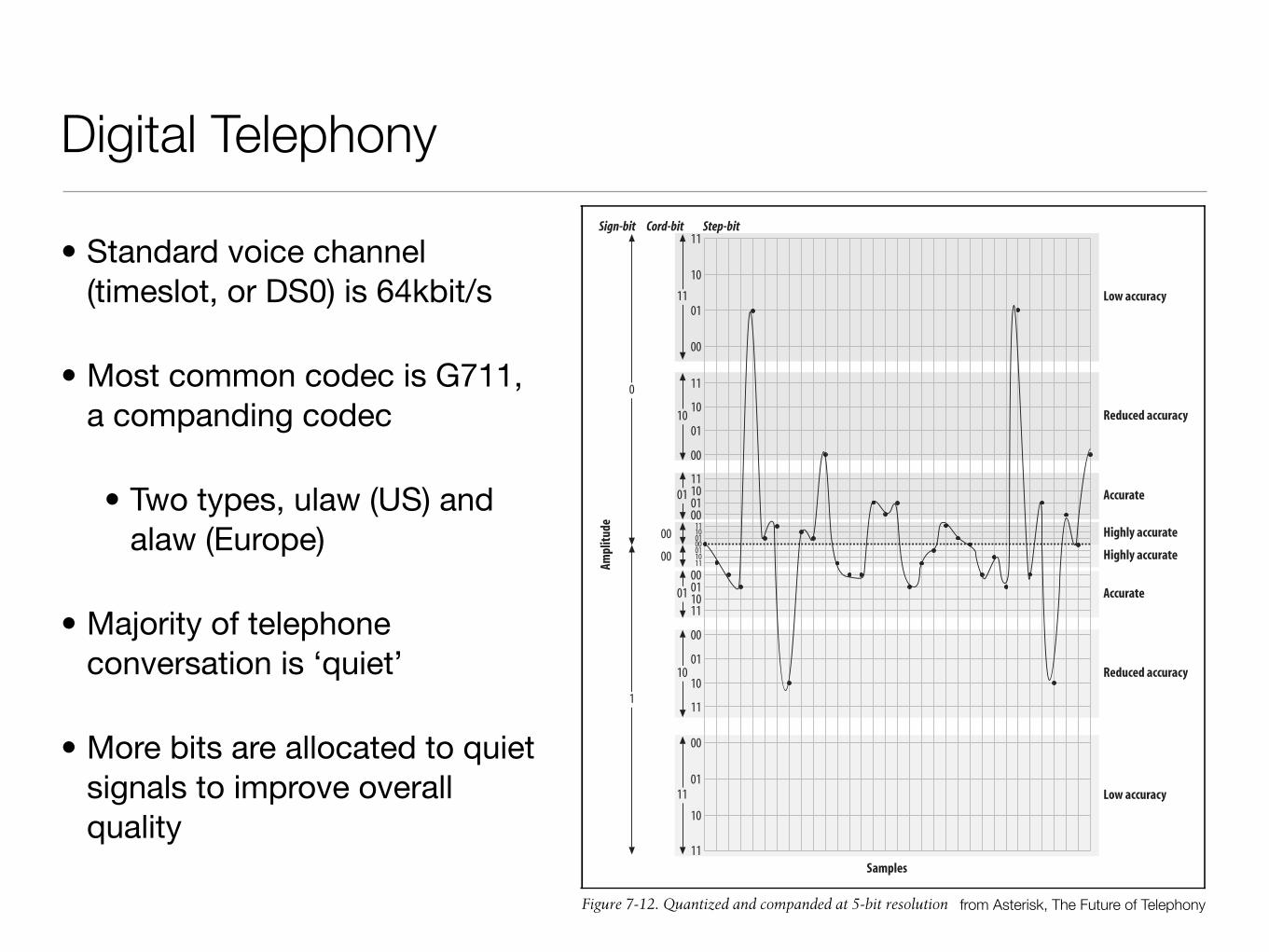
Figure 7-12. Quantized and companded at 5-bit resolution
10
00
11
00
11
00
1011
00
11
00
10
00
01
10
11
10
01
00
00
01
10
11
0
1
Sign-bit Cord-bit Step-bit
Low accuracy
Reduced accuracy
Accurate
Highly accurate
Highly accurate
Accurate
Reduced accuracy
Low accuracy
11
01
10
01
1001
0100011011
0110
01
11
11
Ampl
itude
Samples
,ch07.21568 Page 131 Wednesday, August 31, 2005 4:57 PM
Digital Telephony
• Standard voice channel (timeslot, or DS0) is 64kbit/s
• Most common codec is G711, a companding codec
• Two types, ulaw (US) and alaw (Europe)
• Majority of telephone conversation is ‘quiet’
• More bits are allocated to quiet signals to improve overall quality
from Asterisk, The Future of Telephony
PSTN Circuits
• Analog line
• ISDN
• Basic rate, two voice 64kbit/s voice channels + 16kbit/s data channel -> 144kb/s
• Primary rate
• US - T1, 24 64kbit/s voice channels -> 1.544Mb/s line rate
• Europe - E1, 30 64kbit/s voice channels -> 2.048Mb/s line rate
• Proprietary circuits between key phones and PBXs - not covered here
VoIP
• Natural progression from digital telephony
• Circuit switched --> packet switched
• Still a need to sample and encode signals
• Many different codecs in the VoIP world
• Many different signalling protocols
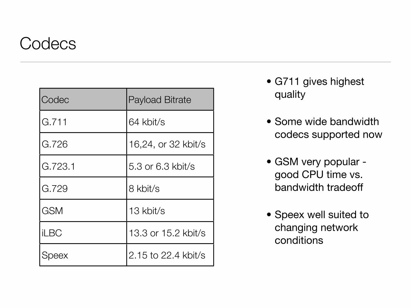
Codecs
• G711 gives highest quality
• Some wide bandwidth codecs supported now
• GSM very popular - good CPU time vs. bandwidth tradeoff
• Speex well suited to changing network conditions
Codec Payload Bitrate
G.711 64 kbit/s
G.726 16,24, or 32 kbit/s
G.723.1 5.3 or 6.3 kbit/s
G.729 8 kbit/s
GSM 13 kbit/s
iLBC 13.3 or 15.2 kbit/s
Speex 2.15 to 22.4 kbit/s
Signalling Protocols
• Signalling protocols needed to allow endpoints and intermediary devices to set up calls
• Common VoIP signalling protocols:
• H.323
• MGCP (Media Gateway Control Protocol)
• Skinny / SCCP (Skinny Client Control Protocol)
• IAX (Inter Asterisk eXchange)
• SIP (Session Initiation Protocol)
H.323
• 10 year old ITU protocol developed to carry multimedia traffic across an IP network
• Actually a suite of protocols, the signalling component being H.245
• Originally designed for video conferencing
• Quickly became de-facto standard for VoIP - and is still used today in many large carrier environments
• Relatively secure and bug free due to its maturity
• Does not work well with NAT at all
• Has all but disappeared in end stations over the past few years
MGCP
• IETF standard, RFC 3345 (obsoletes RFC2705
• Still widely deployed
• Slowly being displaced by SIP
• Being a gateway protocol, has very good gateway features useful for a carrier environment
• Some end phone support for MGCP but never big
Skinny / SCCP
• Cisco Proprietary protocol
• Originally developed by Selius Systems in the mid 1990’s
• Cisco bought them and entered the telephony market :)
• Cisco CallManager based on Skinny, though finally moving to the more standard SIP
• Called Skinny as phones are ‘dumb’.
• SCCP phone events: button X pressed, turn on lamp X, turn off lamp X
IAX
• Developed by Digium, creators of Asterisk
• Apparently it’s pronounced “eeks”. I still say “eye-aye-ex”
• Primarily designed to connect Asterisk servers together
• Has unique ability to trunk multiple calls down one dataflow
• Includes some extra signalling
• Uses a single UDP port, so NAT friendly
• Can use plaintext, MD5, or RSA key exchange for authentication
• IAX, although open source, is not a widely adopted standard
SIP
• SIP is the VoIP protocol these days - RFC 3261 (obsoletes RFC 2543)
• Original (simple!) draft created in 1996
• We’ll be concentrating on SIP and largely ignoring the rest
• It is worth playing around with IAX if you are going to be using Asterisk
• Largely ignored early on it’s life (H.323 was used)
• Largely standard implementations of SIP now
• Not overly NAT friendly, although workarounds exist
• Worthy of a more in-depth look!
What is SIP?
“Session Initiation Protocol (SIP),
an application-layer control (signaling) protocol for creating, modifying, and terminating sessions with one or more participants”
(RFC 3261)
SIP Overview
• ASCII based signalling protocol
• Analogous to HTTP messages
• Works independent of the underlying network transmission protocol
• Provides mechanisms to:
• Establish a session
• Maintain a session
• Modify and Terminate a session
SIP Overview
• Strength is it’s simplicity and basic assumptions
• Component reuse
• A child of SMTP and HTTP
• SIP also uses MIME to carry extra information
• Uses URI Eg: sip:[email protected]
SIP Overview
• Scalable and robust protocol
• Can offload various separate SIP functions to dedicated servers
• Uses distributed architecture
• Very inter-operable protocol (well, these days it is!)
• Supports mobility through use of endpoint registration
• Uses RTP to carry media
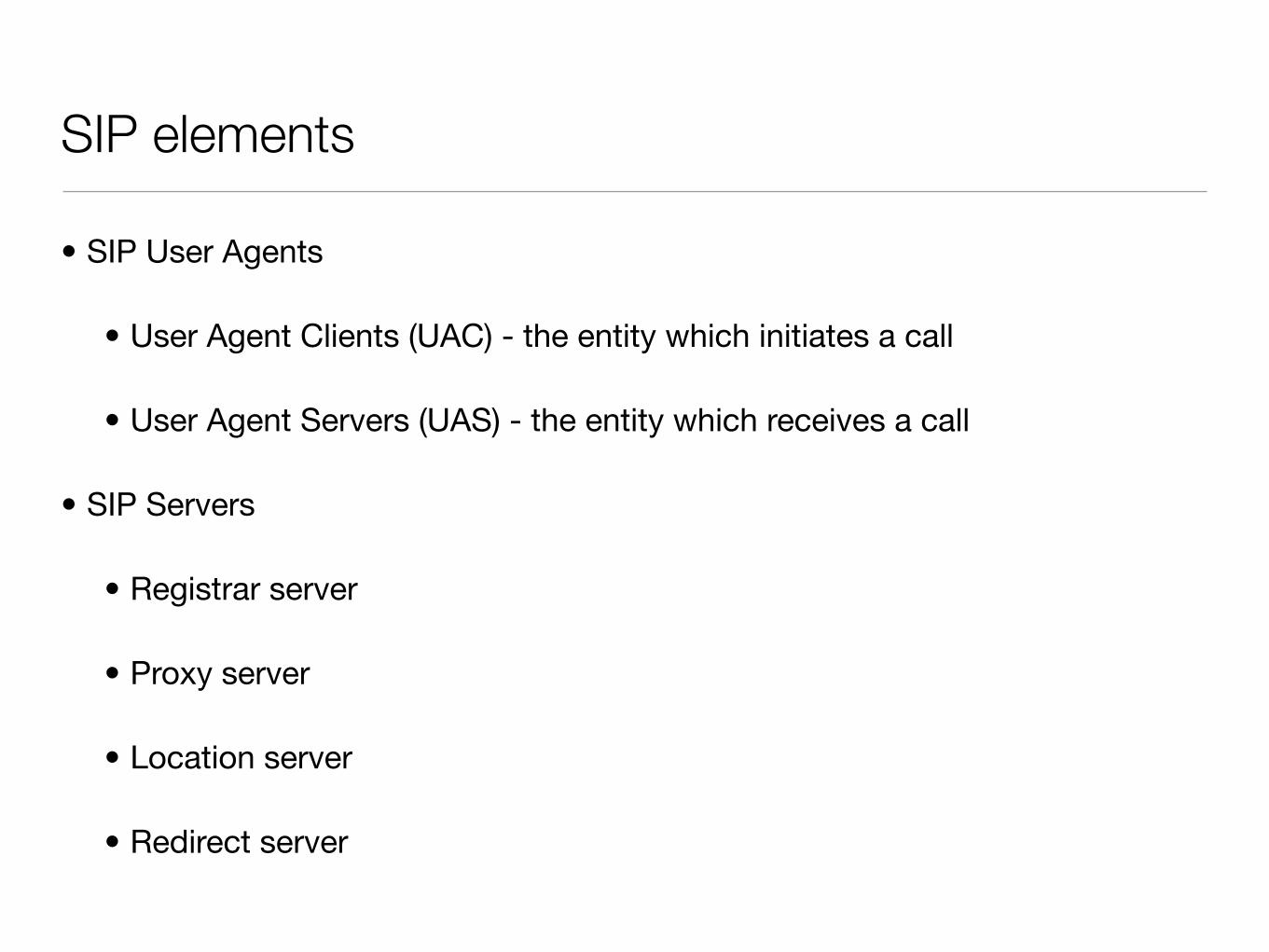
SIP elements
• SIP User Agents
• User Agent Clients (UAC) - the entity which initiates a call
• User Agent Servers (UAS) - the entity which receives a call
• SIP Servers
• Registrar server
• Proxy server
• Location server
• Redirect server
SIP Registrar Server
• Users send registration requests to Registrar server
• Keeps track of client locations
• Supports various forms of authentication
• Often combined with the functionality of a Proxy server (Asterisk does this)
SIP Proxy Server
• Acts both as a server and a client
• Receives SIP messages, forwards to next SIP server
• Can perform functions such as Authentication, Authorisation, and Accounting (AAA)
• Provides network access control
• Requests are serviced internally or by passing them on to other servers.
• Interprets, rewrites or translates a request message before forwarding it.
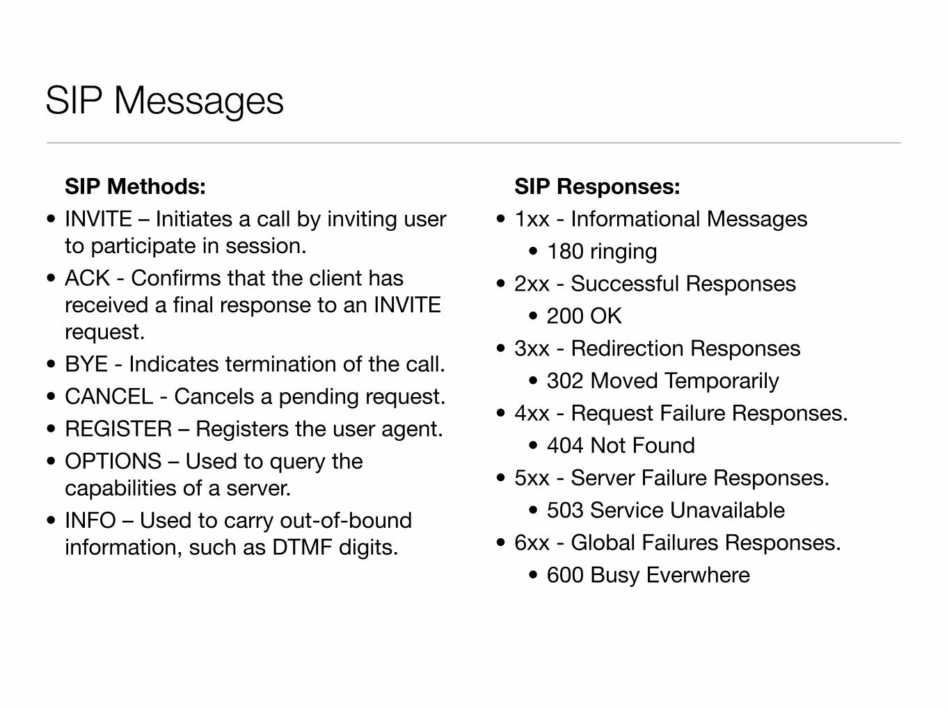
SIP Messages
SIP Methods:• INVITE – Initiates a call by inviting user
to participate in session.
• ACK - Confirms that the client has received a final response to an INVITE request.
• BYE - Indicates termination of the call.
• CANCEL - Cancels a pending request.
• REGISTER – Registers the user agent.
• OPTIONS – Used to query the capabilities of a server.
• INFO – Used to carry out-of-bound information, such as DTMF digits.
SIP Responses:• 1xx - Informational Messages
• 180 ringing
• 2xx - Successful Responses
• 200 OK
• 3xx - Redirection Responses
• 302 Moved Temporarily
• 4xx - Request Failure Responses.
• 404 Not Found
• 5xx - Server Failure Responses.
• 503 Service Unavailable
• 6xx - Global Failures Responses.
• 600 Busy Everwhere
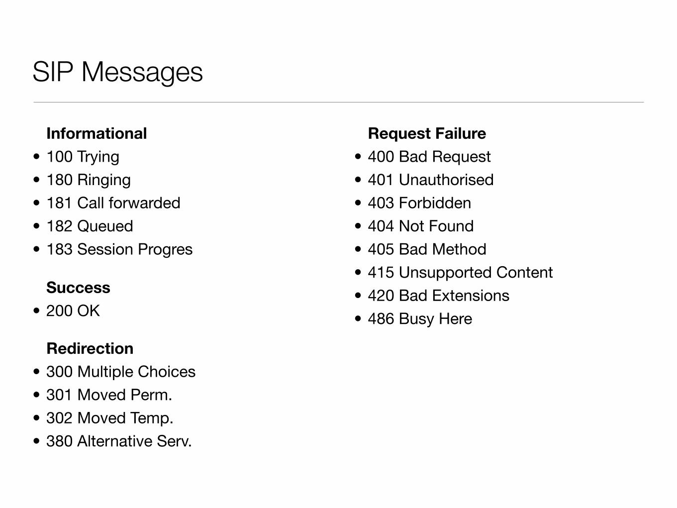
SIP Messages
Informational• 100 Trying
• 180 Ringing
• 181 Call forwarded
• 182 Queued
• 183 Session Progres
Success• 200 OK
Redirection• 300 Multiple Choices
• 301 Moved Perm.
• 302 Moved Temp.
• 380 Alternative Serv.
Request Failure• 400 Bad Request
• 401 Unauthorised
• 403 Forbidden
• 404 Not Found
• 405 Bad Method
• 415 Unsupported Content
• 420 Bad Extensions
• 486 Busy Here
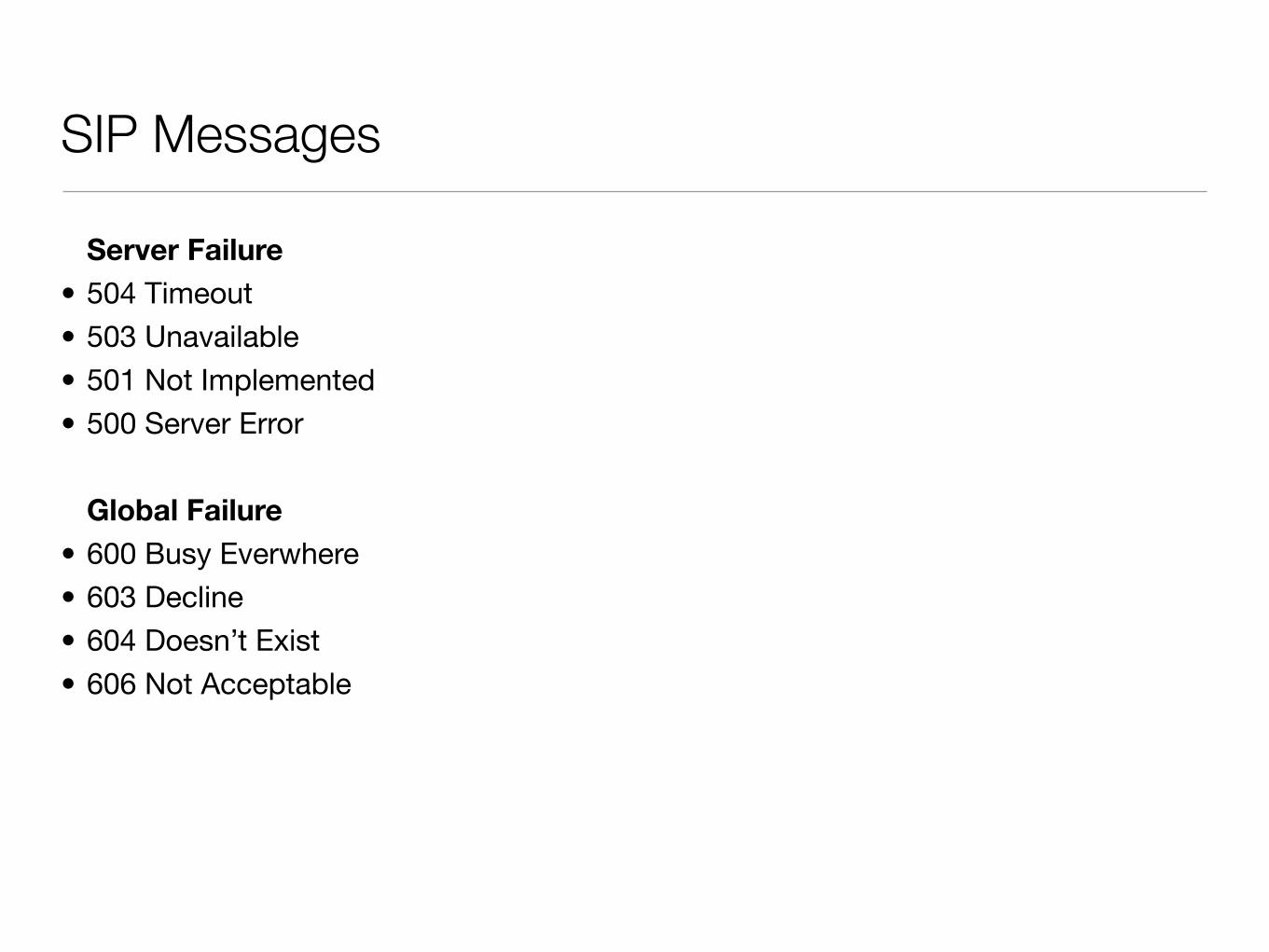
SIP Messages
Server Failure• 504 Timeout
• 503 Unavailable
• 501 Not Implemented
• 500 Server Error
Global Failure• 600 Busy Everwhere
• 603 Decline
• 604 Doesn’t Exist
• 606 Not Acceptable
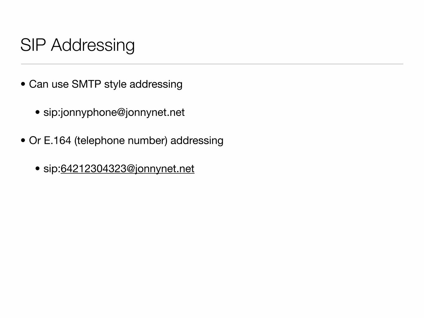
SIP Addressing
• Can use SMTP style addressing
• sip:[email protected]
• Or E.164 (telephone number) addressing
• sip:[email protected]
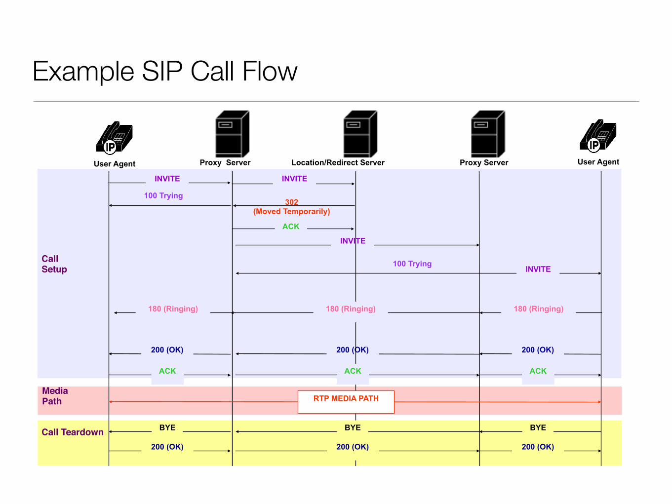
Example SIP Call Flow
302 (Moved Temporarily)
INVITE
200 (OK)200 (OK)
ACK
INVITE
180 (Ringing)180 (Ringing)180 (Ringing)
200 (OK)
ACKACK ACK
RTP MEDIA PATH
BYEBYE BYE
200 (OK)200 (OK) 200 (OK)
Call Teardown
MediaPath
Call Setup
INVITE
Location/Redirect ServerProxy Server Proxy Server User AgentUser Agent
INVITE
100 Trying
100 Trying
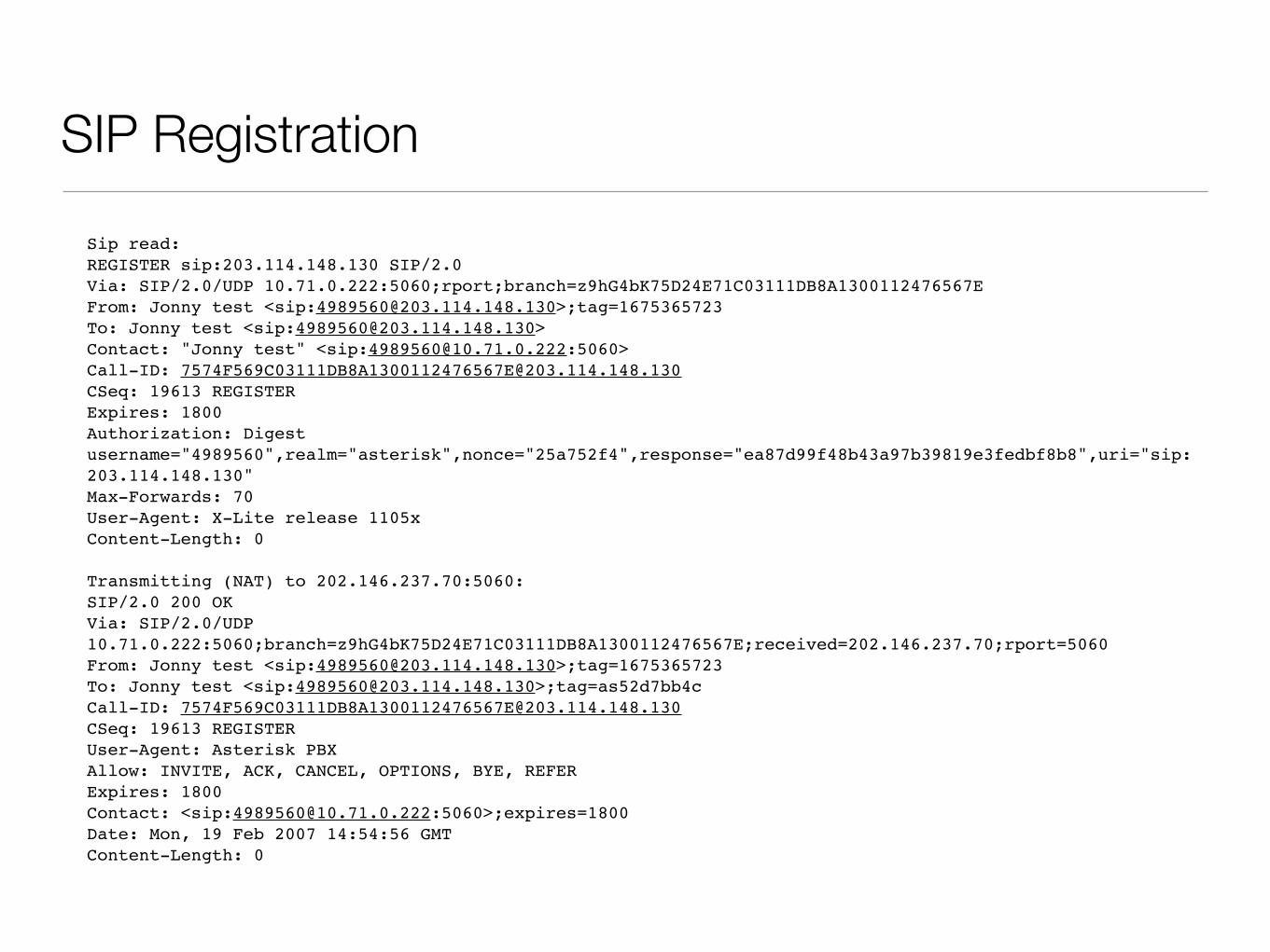
SIP Registration
Sip read:REGISTER sip:203.114.148.130 SIP/2.0Via: SIP/2.0/UDP 10.71.0.222:5060;rport;branch=z9hG4bK75D24E71C03111DB8A1300112476567EFrom: Jonny test <sip:[email protected]>;tag=1675365723To: Jonny test <sip:[email protected]>Contact: "Jonny test" <sip:[email protected]:5060>Call-ID: [email protected]: 19613 REGISTERExpires: 1800Authorization: Digest username="4989560",realm="asterisk",nonce="25a752f4",response="ea87d99f48b43a97b39819e3fedbf8b8",uri="sip:203.114.148.130"Max-Forwards: 70User-Agent: X-Lite release 1105xContent-Length: 0
Transmitting (NAT) to 202.146.237.70:5060:SIP/2.0 200 OKVia: SIP/2.0/UDP 10.71.0.222:5060;branch=z9hG4bK75D24E71C03111DB8A1300112476567E;received=202.146.237.70;rport=5060From: Jonny test <sip:[email protected]>;tag=1675365723To: Jonny test <sip:[email protected]>;tag=as52d7bb4cCall-ID: [email protected]: 19613 REGISTERUser-Agent: Asterisk PBXAllow: INVITE, ACK, CANCEL, OPTIONS, BYE, REFERExpires: 1800Contact: <sip:[email protected]:5060>;expires=1800Date: Mon, 19 Feb 2007 14:54:56 GMTContent-Length: 0
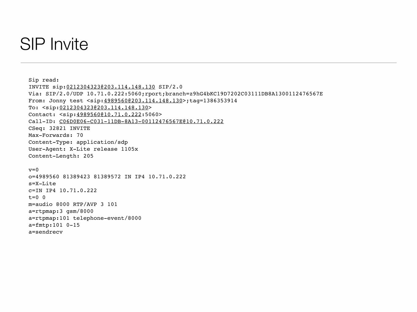
SIP Invite
Sip read: INVITE sip:[email protected] SIP/2.0Via: SIP/2.0/UDP 10.71.0.222:5060;rport;branch=z9hG4bKC19D7202C03111DB8A1300112476567EFrom: Jonny test <sip:[email protected]>;tag=1386353914To: <sip:[email protected]>Contact: <sip:[email protected]:5060>Call-ID: [email protected]: 32821 INVITEMax-Forwards: 70Content-Type: application/sdpUser-Agent: X-Lite release 1105xContent-Length: 205
v=0o=4989560 81389423 81389572 IN IP4 10.71.0.222s=X-Litec=IN IP4 10.71.0.222t=0 0m=audio 8000 RTP/AVP 3 101a=rtpmap:3 gsm/8000a=rtpmap:101 telephone-event/8000a=fmtp:101 0-15a=sendrecv
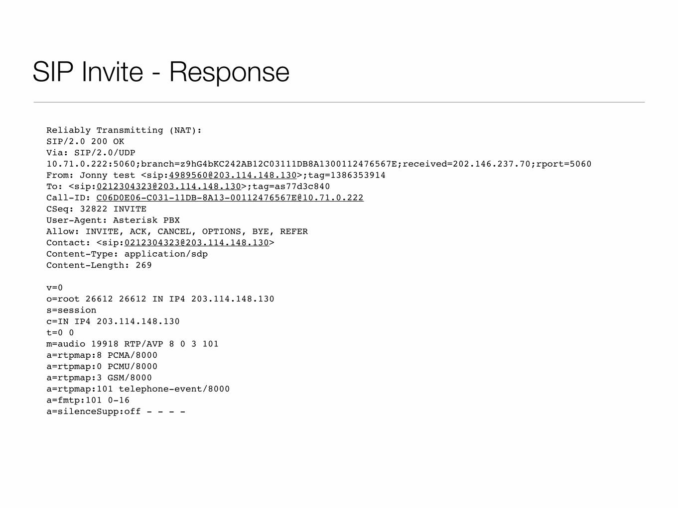
SIP Invite - Response
Reliably Transmitting (NAT):SIP/2.0 200 OKVia: SIP/2.0/UDP 10.71.0.222:5060;branch=z9hG4bKC242AB12C03111DB8A1300112476567E;received=202.146.237.70;rport=5060From: Jonny test <sip:[email protected]>;tag=1386353914To: <sip:[email protected]>;tag=as77d3c840Call-ID: [email protected]: 32822 INVITEUser-Agent: Asterisk PBXAllow: INVITE, ACK, CANCEL, OPTIONS, BYE, REFERContact: <sip:[email protected]>Content-Type: application/sdpContent-Length: 269
v=0o=root 26612 26612 IN IP4 203.114.148.130s=sessionc=IN IP4 203.114.148.130t=0 0m=audio 19918 RTP/AVP 8 0 3 101a=rtpmap:8 PCMA/8000a=rtpmap:0 PCMU/8000a=rtpmap:3 GSM/8000a=rtpmap:101 telephone-event/8000a=fmtp:101 0-16a=silenceSupp:off - - - -
SIP in Detail
• There’s much more to SIP than we can possibly hope to cover here
• Go read the RFC!


