
CISCO VALIDATED DESIGN
REFERENCENETWORK
ARCHITECTURE
IWAN Direct Internet Access Design Guide
December 2016
Table of Contents
Cisco Validated Design
Table of ContentsIntroduction ..................................................................................................................................... 1
Related Reading ...............................................................................................................................................................1
Technology Use Cases .....................................................................................................................................................1
Overview of Cisco IWAN and Secure DIA .......................................................................................................................4
Direct Internet Access Design ........................................................................................................ 10
Design Detail ................................................................................................................................................................. 10
Deploying Direct Internet Access ................................................................................................... 28
Using This Section ........................................................................................................................................................ 28
IWAN Single-Router Hybrid Remote Site with DIA ........................................................................................................ 29
Configuring DIA Routing ................................................................................................................................................ 29
Configuring Single-Router Remote Site with Layer 3 Distribution ................................................................................. 34
Configuring Network Address Translation for DIA .......................................................................................................... 37
Configuring Zone-Based Firewall for DIA ...................................................................................................................... 40
Configuring Additional Router Security .......................................................................................................................... 49
Configuring ISP Black-Hole Routing Detection .............................................................................................................. 53
IWAN Dual-Router Hybrid Remote Site with DIA ........................................................................................................... 59
Configuring DIA Routing ................................................................................................................................................ 60
Configuring Network Address Translation for DIA .......................................................................................................... 68
Configuring Zone-Based Firewall for DIA ...................................................................................................................... 71
Configuring Additional Router Security .......................................................................................................................... 80
Configuring ISP Black-Hole Routing Detection .............................................................................................................. 84
IWAN Single-Router Dual-Internet Remote Site with DIA .............................................................................................. 89
Configuring DIA Routing ................................................................................................................................................ 90
Configuring Single-Router Remote Site with Layer 3 Distribution ................................................................................. 95
Table of Contents
Cisco Validated Design
Configuring Network Address Translation for DIA .......................................................................................................... 98
Configuring Zone-Based Firewall for DIA .................................................................................................................... 101
Configuring Additional Router Security ........................................................................................................................ 113
Configuring ISP Black-Hole Routing Detection ............................................................................................................ 118
IWAN Dual-Router Dual-Internet Remote Site with DIA ............................................................................................... 123
Configuring DIA Routing .............................................................................................................................................. 124
Configuring Network Address Translation for DIA ........................................................................................................ 132
Configuring Zone-Based Firewall for DIA .................................................................................................................... 135
Configuring Additional Router Security ........................................................................................................................ 144
Configuring ISP Black-Hole Routing Detection ............................................................................................................ 148
Appendix A: Product List ............................................................................................................. 154
Appendix B: Router Configurations .............................................................................................. 158
Single-Router Hybrid with DIA .................................................................................................................................... 159
Dual-Router Hybrid with DIA ....................................................................................................................................... 159
Single-Router Dual-Internet with DIA .......................................................................................................................... 161
Dual-Router Dual-Internet with DIA ............................................................................................................................. 162
Appendix C: DIA with PfR Load-Balancing .................................................................................. 163
Configuring DIA with PfR Load-Balancing ................................................................................................................... 163
Appendix D: Changes .................................................................................................................. 166

page 1Cisco Validated Design
Introduction
IntroductionSecurity is an essential component of Cisco Intelligent WAN (IWAN). Cisco IWAN delivers an uncompromised user experience over any connection, allowing an organization to right-size their network with operational simplic-ity and lower costs while reducing security risks.
This guide describes how to reduce WAN bandwidth and improve user experience by enabling secure direct ac-cess to the Internet at each remote site, without routing employee traffic to central network locations.
RELATED READINGThe Intelligent WAN Deployment Guide provides configuration and deployment guidance for IWAN routing with enhanced interior gateway routing protocol (EIGRP) named mode or border gateway protocol (BGP) and open shortest path first (OSPF). It also has guidance for dynamic multipoint virtual private network phase 3 (DMVPNv3), pre-shared key (PSK), public key infrastructure (PKI), and performance routing version 3 (PfRv3) for Cisco IWAN.
TECHNOLOGY USE CASESFor remote-site users to effectively support the business, organizations require that the wide-area network (WAN) provide sufficient performance, reliability, and security.
Although remote-site workers use many centrally located applications and services, there are also benefits in providing direct Internet access (DIA) at each remote-site location. Offloading Internet browsing and providing di-rect access to public cloud service providers can significantly reduce traffic on the private WAN, saving costs and improving overall survivability. Leveraging the cloud in the remote office can also greatly increase performance and the overall cloud experience.
Figure 1 IWAN remote site with DIA
13
21
F
Router withFirewall
InternetDMVPN
Ciscowebex

page 2Cisco Validated Design
Introduction
Use Case: DIA for Remote-Site Internal Employees Remote-site users directly access the Internet for cloud-based applications and user web access without having to route their traffic through a central site over the WAN.
Figure 2 Employee DIA
13
06
F
Internet Ciscowebex
MPLS (IP-VPN)
Employee Private Cloud Access
Employee Direct Internet Access
Branch
ZBFW
PrivateCloud
VirtualPrivate Cloud
Public Cloud
This design guide enables the following network capabilities:
• Offloading Internet traffic from the WAN, thereby reducing bandwidth utilization
• Improving user experience by providing DIA for employees at IWAN remote-site locations
• Deploying Cisco IOS security services for remote users and applications that leverage zone-based firewall (ZBFW), network address translation (NAT), and other integrated network security features
• Resilient routing of local Internet, such as rerouting with local fall back or accessing the Internet through the central site during local Internet failure conditions
page 3Cisco Validated Design
Introduction
Use Case: DIA from Remote-Site Guest Wireless Users
Reader Tip
This use case is discussed in the previous version of the IWAN DIA CVD. If you are interested in deploying Guest Wireless for DIA, see “Deploying Remote Site Guest Wireless Access” in the previous version.
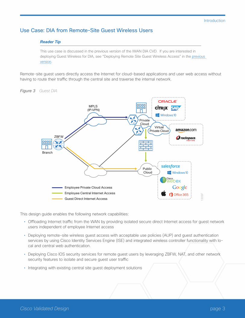
Remote-site guest users directly access the Internet for cloud-based applications and user web access without having to route their traffic through the central site and traverse the internal network.
Figure 3 Guest DIA
13
09
F
Ciscowebex
MPLS (IP-VPN)
Employee Private Cloud Access
Employee Central Internet Access
Guest Direct Internet Access
Branch
ZBFW
Public Cloud
PrivateCloud
VirtualPrivate Cloud
This design guide enables the following network capabilities:
• Offloading Internet traffic from the WAN by providing isolated secure direct Internet access for guest network users independent of employee Internet access
• Deploying remote-site wireless guest access with acceptable use policies (AUP) and guest authentication services by using Cisco Identity Services Engine (ISE) and integrated wireless controller functionality with lo-cal and central web authentication.
• Deploying Cisco IOS security services for remote guest users by leveraging ZBFW, NAT, and other network security features to isolate and secure guest user traffic
• Integrating with existing central site guest deployment solutions

page 4Cisco Validated Design
Introduction
OVERVIEW OF CISCO IWAN AND SECURE DIA This guide provides designs that enable highly available and secure local Internet connectivity for Cisco IWAN remote sites. It shows you how to deploy the network and services in order to enable the following IWAN configu-rations:
• Secure remote-site direct Internet access for employees
While the Internet is quickly becoming a more stable platform with better price to performance and improved reli-ability, it can still fall short of meeting standards for many businesses. With Cisco IWAN, network operations has the security and application services to deliver the highest levels of resiliency and reliability over a variety of WAN transports.
IWAN Remote-Site Design with DIAThe remote-site design provides the remote office with DIA solutions for web browsing and cloud services. This is commonly referred to as the local or direct Internet model where traffic accesses Internet services directly without traversing the WAN. With the direct Internet model, user web traffic and hosted cloud services traffic are permitted to use the local Internet link in a split-tunneling manner. In this model a default route is generated lo-cally, connecting each remote site directly to the Internet provider. Private WAN connections using DMVPN over Internet or MPLS-based WAN services provide a transparent WAN service for internal routes to data center and campus resources.
Figure 4 Central Internet and local Internet comparison
MPLS VPN
1249
F
MPLS VPN
Central Internet(aka central-tunneling)
DMVPNoMPLSto Central Site
DMVPNoINET to Central Site
Direct Internet(aka split-tunneling)
DMVPNoMPLSto Central Site
DMVPNoINET to Central Site
Internet Access and Internal Resources
VPN Tunnel Traffic Only
Internal Resources Only
Internet and VPN Tunnel Traffic
Internet Internet
This guide documents secure, direct Internet-enabled WAN remote-site designs based upon combinations of IP WAN transports, which are mapped to site-specific requirements around service levels and resiliency. WAN transport is transparent and made uniform by using DMVPN tunnels with front door virtual routing and forwarding (FVRF), irrespective of the service from the provider.
page 5Cisco Validated Design
Introduction
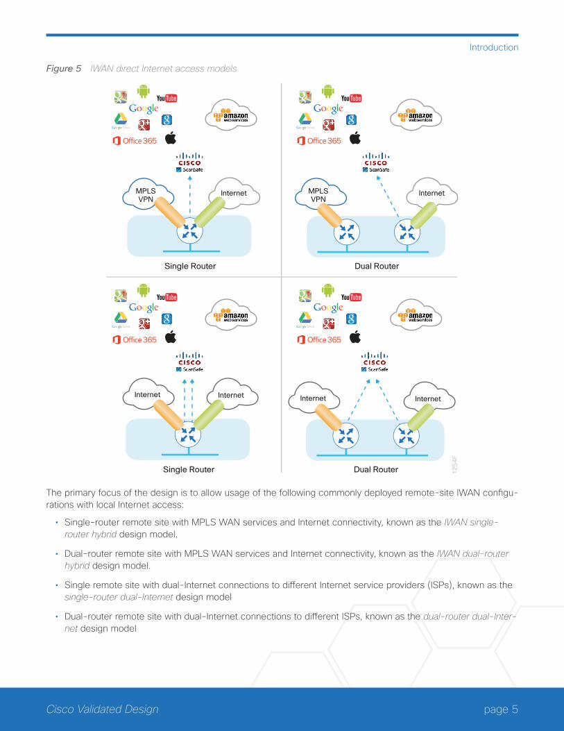
Figure 5 IWAN direct Internet access models
MPLSVPN
Internet
Internet Internet
Single Router
MPLSVPN
Internet
Dual Router
12
54
F
Single Router
InternetInternet
Dual Router
The primary focus of the design is to allow usage of the following commonly deployed remote-site IWAN configu-rations with local Internet access:
• Single-router remote site with MPLS WAN services and Internet connectivity, known as the IWAN single-router hybrid design model.
• Dual-router remote site with MPLS WAN services and Internet connectivity, known as the IWAN dual-router hybrid design model.
• Single remote site with dual-Internet connections to different Internet service providers (ISPs), known as the single-router dual-Internet design model
• Dual-router remote site with dual-Internet connections to different ISPs, known as the dual-router dual-Inter-net design model
page 6Cisco Validated Design
Introduction
Reader Tip
The choice to use locally routed or direct Internet is locally significant to the remote site. No changes are required to the primary site.
The remote-site designs documented in this guide can be deployed in parallel with other remote-site designs that use centralized Internet access.
This guide does not address the primary aggregation site design and configuration details. This solu-tion is tested and evaluated to work with the design models and WAN-aggregation site configurations as outlined in the Intelligent WAN Deployment Guide.
IWAN High AvailabilityThe majority of remote sites are designed with a single-router WAN edge; however, certain remote-site types require a dual-router WAN edge. Dual-router candidate sites include regional office or remote campus loca-tions with large user populations, or sites with business critical needs that justify additional redundancy to remove single points of failure.
The network must tolerate single failure conditions, including the failure of any single WAN transport link or any single network device at the primary remote site. IWAN remote-site designs provide the following high availability options for direct Internet access.
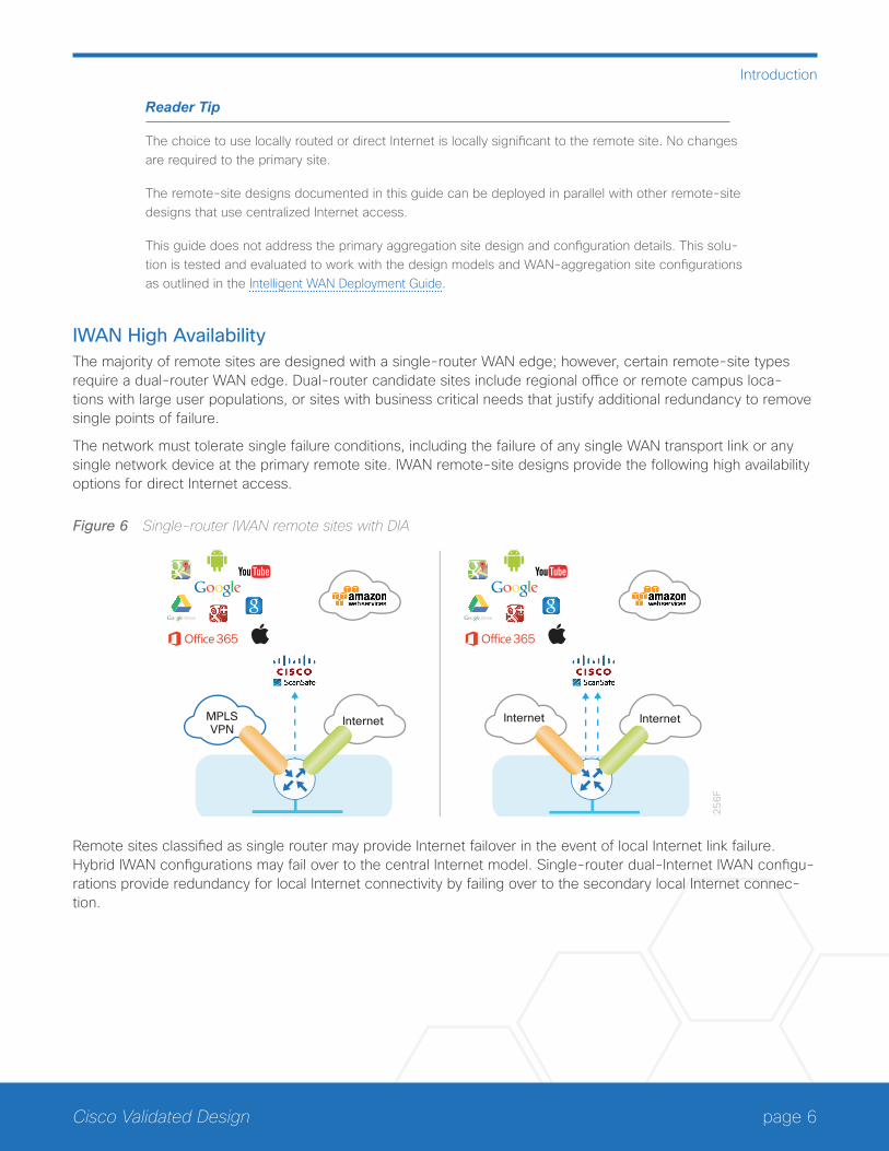
Figure 6 Single-router IWAN remote sites with DIA
InternetMPLSVPN
Internet1
25
6F
Internet
Remote sites classified as single router may provide Internet failover in the event of local Internet link failure. Hybrid IWAN configurations may fail over to the central Internet model. Single-router dual-Internet IWAN configu-rations provide redundancy for local Internet connectivity by failing over to the secondary local Internet connec-tion.
page 7Cisco Validated Design
Introduction
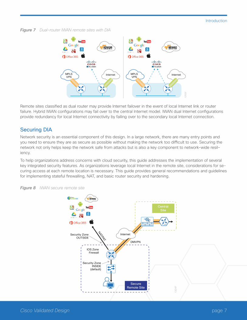
Figure 7 Dual-router IWAN remote sites with DIA
MPLSVPN
Internet MPLSVPN
Internet
12
55
F
Remote sites classified as dual router may provide Internet failover in the event of local Internet link or router failure. Hybrid IWAN configurations may fail over to the central Internet model. IWAN dual Internet configurations provide redundancy for local Internet connectivity by failing over to the secondary local Internet connection.
Securing DIA Network security is an essential component of this design. In a large network, there are many entry points and you need to ensure they are as secure as possible without making the network too difficult to use. Securing the network not only helps keep the network safe from attacks but is also a key component to network-wide resil-iency.
To help organizations address concerns with cloud security, this guide addresses the implementation of several key integrated security features. As organizations leverage local Internet in the remote site, considerations for se-curing access at each remote location is necessary. This guide provides general recommendations and guidelines for implementing stateful firewalling, NAT, and basic router security and hardening.
Figure 8 IWAN secure remote site
13
04
F
CentralSite
SecureRemote Site
IOS ZoneFirewall
DMVPN
Security ZoneOUTSIDE
Security ZoneINSIDE
(default)
NAT/PAT
Internet
Ciscowebex
page 8Cisco Validated Design
Introduction
Network Address TranslationWith the growing adoption of distributed cloud applications, NAT plays an integral role in enabling organizations to deploy and secure public and private cloud services.
NAT enables private IP networks that use unregistered IP addresses (as specified in RFC 1918) to connect to the Internet. NAT is used to translate the private addresses defined on internal networks into legal routable addresses because ISPs cannot route RFC 1918 addresses.
Although it is possible to use public IP addresses internally at a remote site, NAT will most likely still be required. If there are a large number of branches using public IP addresses, it is not possible or desirable to advertise them using BGP. The additional cost of Internet connections with BGP precludes the use of inexpensive broadband services.
Primarily designed for IP address conservation and network design simplification, NAT can also serve as a secu-rity mechanism by hiding a host’s IP address and application ports.
NAT operates on a firewall and routers connecting two network segments and translating the internal private ad-dresses to a public address on the external network. It can be configured to show only one IP address externally. This provides additional security by effectively hiding the entire internal network behind a single IP address. This capability is called port address translation (PAT), also referred to as NAT overload.
NAT provides the following benefits:
• Security, providing an added layer of defense from external attackers by hiding IP addresses and application ports
• Scalability through the reuse of IP addresses, and by using IP address overloading capabilities
• Simplified provisioning and troubleshooting by enforcing consistent network design across network locations
NAT is typically implemented at the edge of the network wherever an organization connects to the Internet. Today, this may be in central or large aggregation sites or in remote sites providing localized Internet services.
Cisco IOS Zone-Based FirewallWith the adoption of remote-site local Internet for user web browsing and cloud services, the deployment of fire-wall services at the remote office Internet edge is critical to maintaining an organization’s security posture.
Zone-based firewall (ZBFW), also called zone policy firewall, is a Cisco IOS-integrated stateful firewall imple-mented on the Cisco Integrated Services Routers (ISR) and Cisco Aggregation Services Routers (ASR) routing platforms.
Firewall zone policies are configured by using the Cisco Common Classification Policy Language (C3PL), which employs a hierarchical structure to define inspection for network protocols and the groups to which the inspection will be applied. Users familiar with the Cisco IOS modular quality of service CLI (MQC) will recognize the use of class maps to specify which traffic will be affected by the action applied in a policy map.
Within this model, router interfaces are assigned to security zones, which establish the security borders of your network. A security zone defines a boundary where traffic is subjected to policy restrictions; this policy is called a zone policy. Zone policies define what traffic is allowed to flow between security zones. Zone policies are uni-directional firewall policies applied between two security zones, called a zone pair. A zone pair is defined as two security zones between which a zone policy is applied.
page 9Cisco Validated Design
Introduction
Router interfaces assigned to configured security zones are subject to the default policies and rules:
• An interface can be a member of only a single security zone.
• A security zone can contain only member interfaces that are all in the same virtual routing and forwarding (VRF); interfaces in different VRFs may not be part of the same security zone.
• When an interface is placed into a security zone, traffic is implicitly allowed to flow between other interfaces assigned to the same security zone.
• Traffic flow to interfaces in different security zones is denied with an implicit deny all zone policy.
• Traffic cannot flow between an interface that is a member of a security zone and any interface that is not a member of a security zone. Instead, the traffic is dropped. If the default zone configuration is implemented as is described in this guide, traffic can flow between interfaces without security zone configurations because all interfaces automatically become part of the default zone.
• To allow traffic to flow between different security zones, policies must be configured between any two secu-rity zones.
• Pass, inspect, and drop actions can only be applied between two zones.
• By default, traffic (for instance, a routing protocol) that flows to and from the router itself is permitted. The router (as a source and destination) is defined as the self-zone by the Cisco IOS firewall. Traffic to and from the self-zone on any interface is allowed until traffic is explicitly denied by a user-defined zone security policy.

page 10Cisco Validated Design
Direct Internet Access Design
Direct Internet Access DesignDESIGN DETAILThis guide focuses on four remote-site designs with DIA. These designs provide configurations and guidance for enabling secure localized Internet access in remote office locations.
Each of the Cisco IWAN remote-site design options support DIA and internal network communications with the central site. All designs support resilient routing.
The IWAN hybrid direct Internet access designs are:
• Single-router hybrid designs, MPLS and Internet
• Dual-router hybrid designs, MPLS and Internet
Figure 9 IWAN hybrid design models with DIA
MPLSVPN
Internet MPLSVPN
Internet
12
57
F
page 11Cisco Validated Design
Direct Internet Access Design
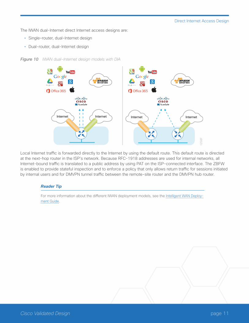
The IWAN dual-Internet direct Internet access designs are:
• Single-router, dual-Internet design
• Dual-router, dual-Internet design
Figure 10 IWAN dual-Internet design models with DIA
InternetInternet Internet Internet
12
58
F
Local Internet traffic is forwarded directly to the Internet by using the default route. This default route is directed at the next-hop router in the ISP’s network. Because RFC-1918 addresses are used for internal networks, all Internet-bound traffic is translated to a public address by using PAT on the ISP-connected interface. The ZBFW is enabled to provide stateful inspection and to enforce a policy that only allows return traffic for sessions initiated by internal users and for DMVPN tunnel traffic between the remote-site router and the DMVPN hub router.
Reader Tip
For more information about the different IWAN deployment models, see the Intelligent WAN Deploy-ment Guide.

page 12Cisco Validated Design
Direct Internet Access Design
IWAN DIA Routing with Front Door VRF All IWAN designs are based on the use of front door virtual routing and forwarding (FVRF) with DMVPN to seg-ment the routing table, thus allowing two default routes to exist on the same router.
With FVRF, the default route from the ISP is contained within the Internet facing VRF and is only used for DMVPN tunnel formation. A default route is obtained from the local ISP by using DHCP and is added to the outside VRF with a default administrative distance (AD) value of 254.
Figure 11 IWAN FVRF routing—VRF default route
12
50
F
VRF IWAN-TRANSPORT-2
G0/0/1
DHCP DerivedDefault Route from ISP0.0.0.0 0.0.0.0Default Distance 254VRF IWAN-TRANSPORT-2
Global Table
Internet
In the base IWAN configuration, a second default route is contained in the global table. In this central Internet model, the global table default route directs traffic over the tunnel interfaces.
When a remote site is converted to use a local or direct Internet model, the global default route needs to direct traffic outside the Internet facing DMVPN tunnel to the Internet.
In the direct Internet model, a default route over Internet-based VPN tunnels cannot be allowed. In this case, be-cause backup Internet routing is not possible over these VPN tunnels, the recommended best practice is to filter the central-site default route.
Figure 12 IWAN FVRF routing—global to VRF outbound
12
51
F
G0/0/1
DHCP DerivedDefault Route 0.0.0.0 0.0.0.0Default Distance 254VRF IWAN-TRANSPORT-2
From Global to IWAN-TRANSPORT-2
(via G0/0/1)
Default Route 0.0.0.0 0.0.0.0Default Distance 10
DM
VP
No
INE
T
VRF IWAN-TRANSPORT-2
Global Table
Internet

page 13Cisco Validated Design
Direct Internet Access Design
When FVRF is used, the return traffic from the Internet to the remote site router needs to traverse from the out-side facing Internet VRF to the global routing table. In IWAN configurations, a local policy route must be used to move return traffic from the outside VRF into the global table that is destined to the internal remote site network.
Figure 13 IWAN FVRF routing—return VRF to global routing
Internet
70
05
F
G0/0/1
From IWAN-TRANSPORT-2to Global
Policy Route for 10.0.0.0/8 traffic Set next-hop VRF to Global Table
VRF IWAN-TRANSPORT-2
Global Table
DM
VP
No
INE
T
IWAN Single-Router Hybrid Remote-Site RoutingIn this design, the remote site is configured with a single router by using DMVPN over MPLS as the primary con-nectivity for internal traffic. This site also uses an Internet connection on the same router for DMVPN over the Internet as an alternate path.
In the hybrid design with DIA, Internet traffic is routed outside the DMVPN tunnel for local Internet access. In this configuration, the local path is primary with failover to the central site Internet connectivity by using the MPLS-based DMVPN tunnel.
Figure 14 IWAN single-router hybrid with DIA
12
60
FDirect Internet Access
0.0.0.0 0.0.0.0
DMVPNoM
PLS
IOSNAT/FW
DMVPNoINET
Ciscowebex
Internet
MPLSVPN

page 14Cisco Validated Design
Direct Internet Access Design
With IWAN, internal networks are advertised using the WAN routing protocol over the DMVPN tunnels, preferring the MPLS-based path. Based on performance routing (PfR) policy, critical internal traffic or traffic that stays within the organization is routed primarily over the MPLS-based WAN tunnel and alternatively over the Internet-based DMVPN tunnel. If the MPLS-based DMVPN tunnel fails, all internal traffic is routed to the central site by using DMVPN over the Internet.
Figure 15 IWAN single-router hybrid design—routing
Global Table
12
62
F
G0/0/1
DHCP DerivedDefault Route from ISP0.0.0.0 0.0.0.0Default Distance 254VRF IWAN-TRANSPORT-2
DM
VP
No
INE
T
DM
VP
No
MP
LSInternetMPLS
VPN
In this example, the Internet facing Ethernet interface on the router is using DHCP to obtain an IP address from the ISP. The router is also using DHCP to install a default route into the outside VRF routing table. By default, this DHCP-installed static route has an AD value of 254.
In this case, the default route to the local ISP is isolated in the VRF IWAN-TRANSPORT-2 and used for DMVPN tunnel setup and to route traffic from the outside VRF to the Internet. The default route is used for both Internet protocol service-level agreement (IPSLA) and DIA traffic.
Figure 16 IWAN single-router hybrid—global default
Global Table
70
06
F
G0/0/1
Primary Internet PathFrom Global to IWAN-TRANSPORT-2(via G0/0/1)
Default Route 0.0.0.0 0.0.0.0Admin Distance 10
Filter Central-siteDefault Route0.0.0.0 0.0.0.0
Secondary Internet Path(optional)
Central-site Default Route0.0.0.0 0.0.0.0
Global Table
InternetMPLSVPN
DM
VP
No
INE
T
DM
VP
No
MP
LS
page 15Cisco Validated Design
Direct Internet Access Design
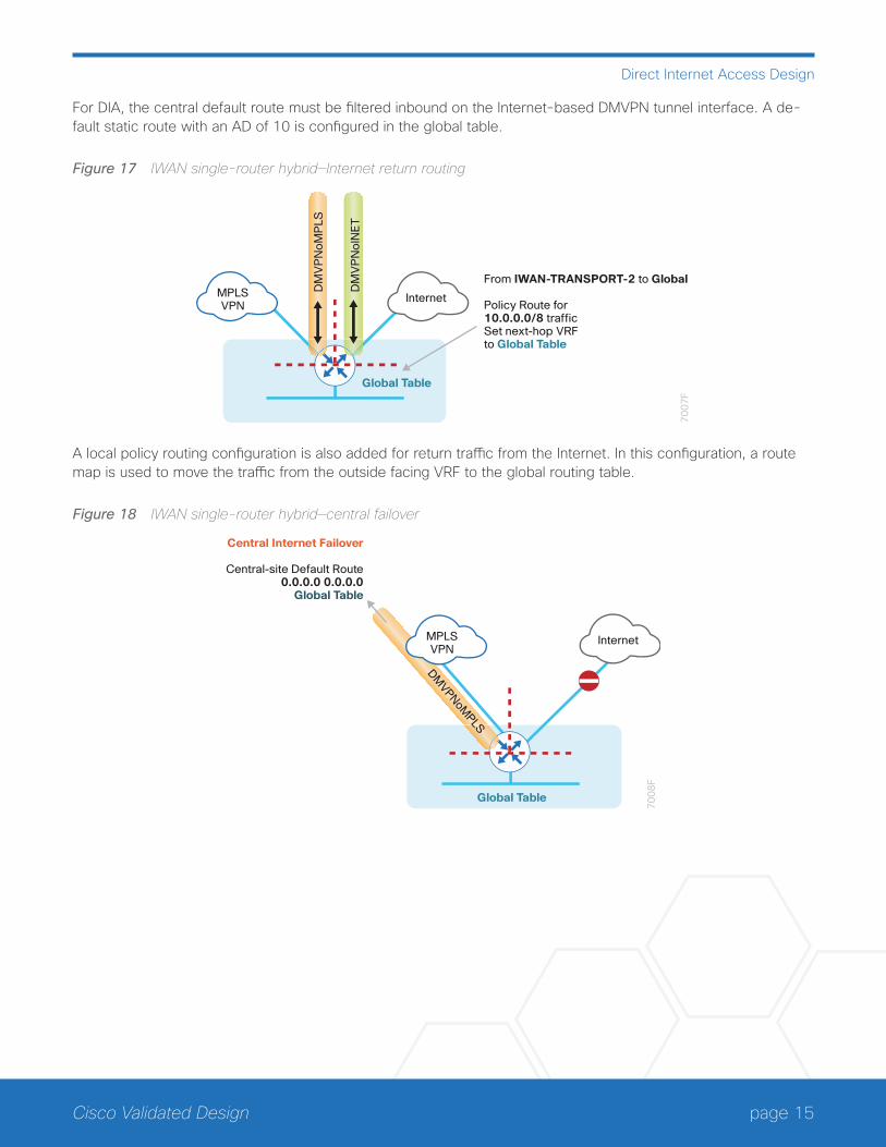
For DIA, the central default route must be filtered inbound on the Internet-based DMVPN tunnel interface. A de-fault static route with an AD of 10 is configured in the global table.
Figure 17 IWAN single-router hybrid—Internet return routing
Global Table
70
07
F
DM
VP
No
INE
T
DM
VP
No
MP
LS
InternetMPLSVPN
From IWAN-TRANSPORT-2 to Global
Policy Route for 10.0.0.0/8 traffic Set next-hop VRFto Global Table
A local policy routing configuration is also added for return traffic from the Internet. In this configuration, a route map is used to move the traffic from the outside facing VRF to the global routing table.
Figure 18 IWAN single-router hybrid—central failover
70
08
F
Central Internet Failover
Central-site Default Route0.0.0.0 0.0.0.0
Global Table
DMVPNoM
PLS
Global Table
InternetMPLSVPN
page 16Cisco Validated Design
Direct Internet Access Design
In this configuration, the MPLS-based tunnel can be used as a backup path for Internet if the local Internet con-nection fails. The central-site default route is advertised over the MPLS-based tunnel and is used only if the local connection fails.
Tech Tip
This configuration requires you to turn off PfR load-balancing on the Hub Master Controller. If PfR load-balancing is not turned off, the traffic will fail over to the central site Internet path, but it will not return to the local DIA interface after the failure condition is resolved.
If PfR load-balancing is a requirement for your environment, see “Appendix C: DIA with PfR Load-Balancing” for an alternate way to configure your hybrid remote sites.
If PfR load-balancing is not required, DMVPN tunnel state and IPSLA probes are used to determine the availability of the primary local Internet connection. If a failure is detected, an Embedded Event Manager script removes the default static route. Instead, the central default route via the MPLS-based DMVPN tunnel is used.
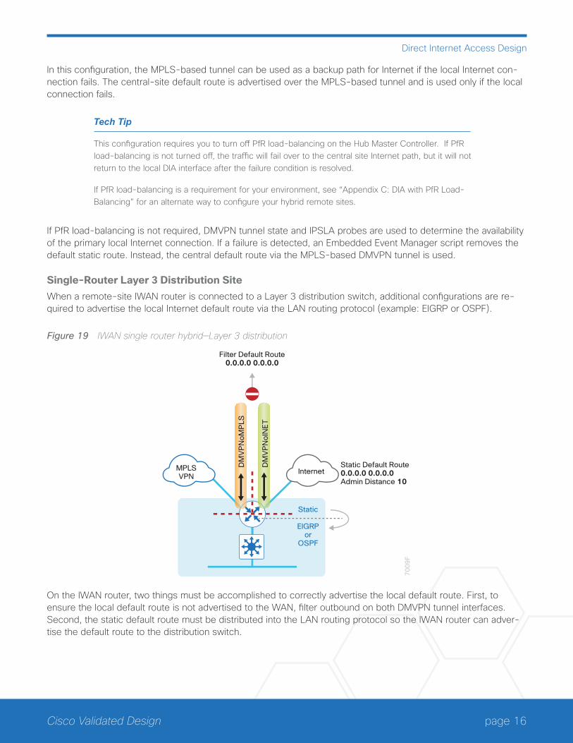
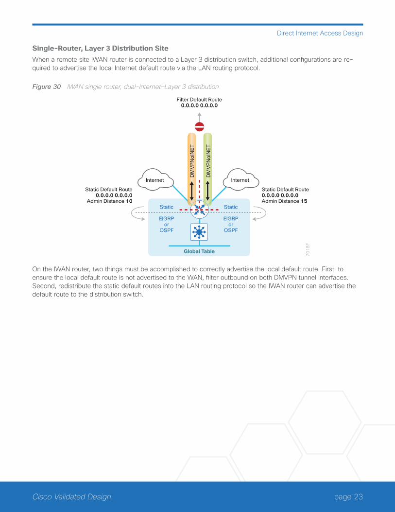
Single-Router Layer 3 Distribution SiteWhen a remote-site IWAN router is connected to a Layer 3 distribution switch, additional configurations are re-quired to advertise the local Internet default route via the LAN routing protocol (example: EIGRP or OSPF).
Figure 19 IWAN single router hybrid—Layer 3 distribution
70
09
F
Filter Default Route0.0.0.0 0.0.0.0
DM
VP
No
INE
T
DM
VP
No
MP
LS
Static Default Route 0.0.0.0 0.0.0.0Admin Distance 10
Static
EIGRPor
OSPF
InternetMPLSVPN
On the IWAN router, two things must be accomplished to correctly advertise the local default route. First, to ensure the local default route is not advertised to the WAN, filter outbound on both DMVPN tunnel interfaces. Second, the static default route must be distributed into the LAN routing protocol so the IWAN router can adver-tise the default route to the distribution switch.

page 17Cisco Validated Design
Direct Internet Access Design
IWAN Dual-Router Hybrid Remote Site RoutingIn this design, the remote site is configured with dual routers. The primary router uses DMVPN over MPLS as the primary connection for internal traffic. This site also uses a secondary router with an Internet connection for DMVPN over the Internet as an alternate path.
In the hybrid design with DIA the Internet traffic is routed outside the DMVPN tunnel for local Internet access on the secondary router. In this configuration, the local path is primary with failover to the central site Internet con-nectivity by using the MPLS-based DMVPN tunnel on the primary router.
Figure 20 IWAN dual-router hybrid with DIA
12
74
F
Direct Internet Access0.0.0.0 0.0.0.0
HSRP
DMVPNoINET
DMVPNoMPLS
DHCP
Ciscowebex
Internet
MPLSVPN
With IWAN, internal networks are advertised by the WAN routing protocol over the DMVPN tunnels, preferring the MPLS-based path on the primary router. Based on PfR policy, critical internal traffic or traffic that stays within the organization is routed primarily over the MPLS-based WAN tunnel and alternatively over the Internet-based DMVPN tunnel on the secondary router. In the case of a failure on the primary router, all internal traffic is routed to the central site by using DMVPN over the Internet on the secondary router.
Figure 21 IWAN dual-router hybrid—VRF routing
70
10
F
DM
VP
No
INE
T
DM
VP
No
MP
LS
DHCP DerivedDefault Route from ISP0.0.0.0 0.0.0.0Default Distance 254VRF IWAN-TRANSPORT-2
Global Table
InternetMPLS
page 18Cisco Validated Design
Direct Internet Access Design
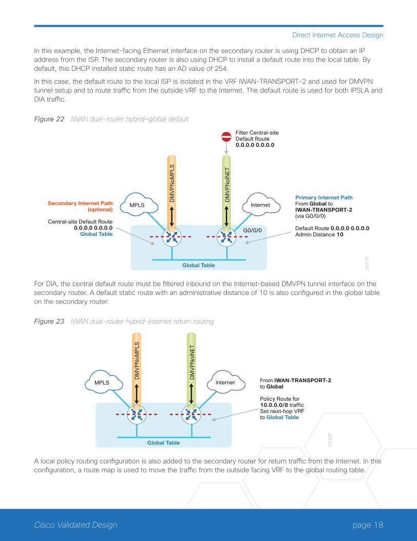
In this example, the Internet-facing Ethernet interface on the secondary router is using DHCP to obtain an IP address from the ISP. The secondary router is also using DHCP to install a default route into the local table. By default, this DHCP installed static route has an AD value of 254.
In this case, the default route to the local ISP is isolated in the VRF IWAN-TRANSPORT-2 and used for DMVPN tunnel setup and to route traffic from the outside VRF to the Internet. The default route is used for both IPSLA and DIA traffic.
Figure 22 IWAN dual-router hybrid—global default
70
11
F
Secondary Internet Path(optional)
Central-site Default Route0.0.0.0 0.0.0.0
Global Table
Primary Internet PathFrom Global toIWAN-TRANSPORT-2(via G0/0/0)
Default Route 0.0.0.0 0.0.0.0Admin Distance 10
Filter Central-siteDefault Route0.0.0.0 0.0.0.0
DM
VP
No
INE
T
DM
VP
No
MP
LS
Global Table
InternetMPLS
G0/0/0
For DIA, the central default route must be filtered inbound on the Internet-based DMVPN tunnel interface on the secondary router. A default static route with an administrative distance of 10 is also configured in the global table on the secondary router.
Figure 23 IWAN dual-router hybrid—Internet return routing7
01
2F
From IWAN-TRANSPORT-2 to Global
Policy Route for 10.0.0.0/8 traffic Set next-hop VRF to Global Table
DM
VP
No
INE
T
DM
VP
No
MP
LS
Global Table
InternetMPLS
A local policy routing configuration is also added to the secondary router for return traffic from the Internet. In this configuration, a route map is used to move the traffic from the outside facing VRF to the global routing table.
page 19Cisco Validated Design
Direct Internet Access Design
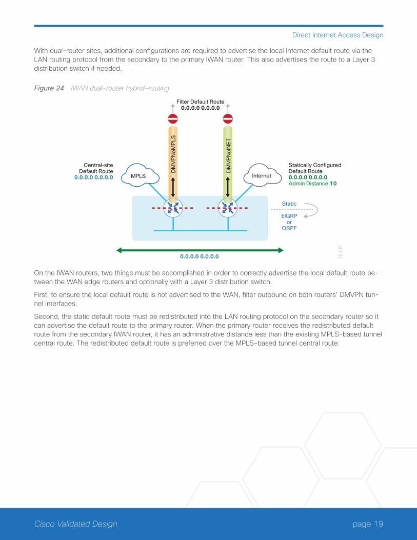
With dual-router sites, additional configurations are required to advertise the local Internet default route via the LAN routing protocol from the secondary to the primary IWAN router. This also advertises the route to a Layer 3 distribution switch if needed.
Figure 24 IWAN dual-router hybrid—routing
DM
VP
No
INE
T
DM
VP
No
MP
LSInternetMPLS
70
13
F
Statically ConfiguredDefault Route0.0.0.0 0.0.0.0Admin Distance 10
Central-siteDefault Route
0.0.0.0 0.0.0.0
Filter Default Route0.0.0.0 0.0.0.0
0.0.0.0 0.0.0.0
Static
EIGRPor
OSPF
On the IWAN routers, two things must be accomplished in order to correctly advertise the local default route be-tween the WAN edge routers and optionally with a Layer 3 distribution switch.
First, to ensure the local default route is not advertised to the WAN, filter outbound on both routers’ DMVPN tun-nel interfaces.
Second, the static default route must be redistributed into the LAN routing protocol on the secondary router so it can advertise the default route to the primary router. When the primary router receives the redistributed default route from the secondary IWAN router, it has an administrative distance less than the existing MPLS-based tunnel central route. The redistributed default route is preferred over the MPLS-based tunnel central route.
page 20Cisco Validated Design
Direct Internet Access Design
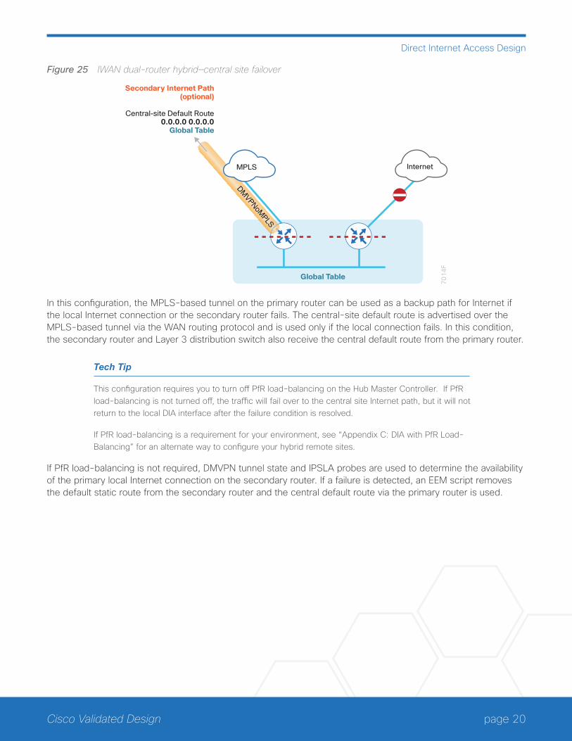
Figure 25 IWAN dual-router hybrid—central site failover
70
14
F
Secondary Internet Path(optional)
Central-site Default Route0.0.0.0 0.0.0.0
Global Table
DMVPNoM
PLS
InternetMPLS
Global Table
In this configuration, the MPLS-based tunnel on the primary router can be used as a backup path for Internet if the local Internet connection or the secondary router fails. The central-site default route is advertised over the MPLS-based tunnel via the WAN routing protocol and is used only if the local connection fails. In this condition, the secondary router and Layer 3 distribution switch also receive the central default route from the primary router.
Tech Tip
This configuration requires you to turn off PfR load-balancing on the Hub Master Controller. If PfR load-balancing is not turned off, the traffic will fail over to the central site Internet path, but it will not return to the local DIA interface after the failure condition is resolved.
If PfR load-balancing is a requirement for your environment, see “Appendix C: DIA with PfR Load-Balancing” for an alternate way to configure your hybrid remote sites.
If PfR load-balancing is not required, DMVPN tunnel state and IPSLA probes are used to determine the availability of the primary local Internet connection on the secondary router. If a failure is detected, an EEM script removes the default static route from the secondary router and the central default route via the primary router is used.
page 21Cisco Validated Design
Direct Internet Access Design
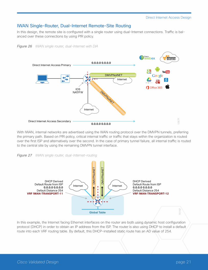
IWAN Single-Router, Dual-Internet Remote-Site RoutingIn this design, the remote site is configured with a single router using dual-Internet connections. Traffic is bal-anced over these connections by using PfR policy.
Figure 26 IWAN single router, dual-Internet with DIA
12
67
F
Direct Internet Access Primary0.0.0.0 0.0.0.0
DMVPNoINET
IOSNAT/FW
DMVPNoINET
Direct Internet Access Secondary0.0.0.0 0.0.0.0
Ciscowebex
Internet
Internet
With IWAN, internal networks are advertised using the WAN routing protocol over the DMVPN tunnels, preferring the primary path. Based on PfR policy, critical internal traffic or traffic that stays within the organization is routed over the first ISP and alternatively over the second. In the case of primary tunnel failure, all internal traffic is routed to the central site by using the remaining DMVPN tunnel interface.
Figure 27 IWAN single router, dual-Internet—routing
Global Table
70
15
F
DM
VP
No
INE
T
DM
VP
No
INE
T
InternetInternet
DHCP DerivedDefault Route from ISP0.0.0.0 0.0.0.0Default Distance 254VRF IWAN-TRANSPORT-12
DHCP DerivedDefault Route from ISP
0.0.0.0 0.0.0.0Default Distance 254
VRF IWAN-TRANSPORT-11
In this example, the Internet facing Ethernet interfaces on the router are both using dynamic host configuration protocol (DHCP) in order to obtain an IP address from the ISP. The router is also using DHCP to install a default route into each VRF routing table. By default, this DHCP-installed static route has an AD value of 254.

page 22Cisco Validated Design
Direct Internet Access Design
In this case, the default routes to the Internet are isolated in the outside VRFs IWAN-TRANSPORT-11 and IWAN-TRANSPORT-12 and are used for DMVPN tunnel setup and to route traffic from the outside VRF to the Internet. The default routes are used for both IPSLA and DIA traffic.
Figure 28 IWAN single router, dual-Internet—global default
Global Table
70
16
F
DM
VP
No
INE
T
DM
VP
No
INE
T
InternetInternet
Secondary Internet Path
From Global to IWAN-TRANSPORT-12(via G0/0/1)
Default Route 0.0.0.0 0.0.0.0Admin Distance 15
Primary Internet Path
From Global to IWAN-TRANSPORT-11(via G0/0/0)
Default Route 0.0.0.0 0.0.0.0Admin Distance 10
G0/0/1G0/0/0
For DIA, the central default route must be filtered inbound on the Internet-based DMVPN tunnel interfaces. A default static route with an administrative distance of 10 is configured in the global table for the primary ISP and a second default static route with a distance of 15 for the secondary ISP connection.
Figure 29 IWAN single router, dual-Internet—Internet return routing
Global Table7
01
7F
DM
VP
No
INE
T
DM
VP
No
INE
T
InternetInternet From IWAN-TRANSPORT-12 to Global
Policy Route for 10.0.0.0/8 traffic Set next-hop VRF to Global Table
From IWAN-TRANSPORT-11 to Global
Policy Route for 10.0.0.0/8 trafficSet next-hop VRF to Global Table
A local policy routing configuration is also added for return traffic from the Internet. In this configuration, a route map is used to move the traffic from the outside facing VRF to the global routing table inbound on both Internet facing interfaces.
In this configuration, if the primary ISP connection fails, all locally routed Internet traffic is routed to the secondary ISP.
DMVPN tunnel state and IPSLA probes are used to determine the availability of the primary local Internet con-nection. If a failure is detected, an EEM script removes the primary default static route and the secondary static default route with an administrative distance of 15 is used instead.
page 23Cisco Validated Design
Direct Internet Access Design
Single-Router, Layer 3 Distribution SiteWhen a remote site IWAN router is connected to a Layer 3 distribution switch, additional configurations are re-quired to advertise the local Internet default route via the LAN routing protocol.
Figure 30 IWAN single router, dual-Internet—Layer 3 distribution
70
18
F
Filter Default Route0.0.0.0 0.0.0.0
DM
VP
No
INE
T
DM
VP
No
INE
TStatic Default Route 0.0.0.0 0.0.0.0Admin Distance 15
Static Default Route0.0.0.0 0.0.0.0
Admin Distance 10Static
EIGRPor
OSPF
Static
EIGRPor
OSPF
InternetInternet
Global Table
On the IWAN router, two things must be accomplished to correctly advertise the local default route. First, to ensure the local default route is not advertised to the WAN, filter outbound on both DMVPN tunnel interfaces. Second, redistribute the static default routes into the LAN routing protocol so the IWAN router can advertise the default route to the distribution switch.
page 24Cisco Validated Design
Direct Internet Access Design
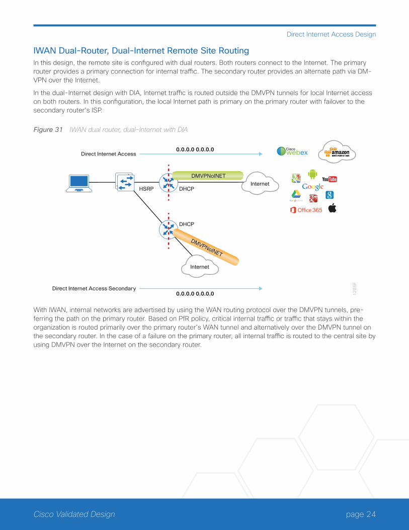
IWAN Dual-Router, Dual-Internet Remote Site RoutingIn this design, the remote site is configured with dual routers. Both routers connect to the Internet. The primary router provides a primary connection for internal traffic. The secondary router provides an alternate path via DM-VPN over the Internet.
In the dual-Internet design with DIA, Internet traffic is routed outside the DMVPN tunnels for local Internet access on both routers. In this configuration, the local Internet path is primary on the primary router with failover to the secondary router’s ISP.
Figure 31 IWAN dual router, dual-Internet with DIA
12
86
F
Direct Internet Access0.0.0.0 0.0.0.0
HSRP
DMVPNoINET
DMVPNoINET
DHCP
Ciscowebex
DHCP
Direct Internet Access Secondary0.0.0.0 0.0.0.0
Internet
Internet
With IWAN, internal networks are advertised by using the WAN routing protocol over the DMVPN tunnels, pre-ferring the path on the primary router. Based on PfR policy, critical internal traffic or traffic that stays within the organization is routed primarily over the primary router’s WAN tunnel and alternatively over the DMVPN tunnel on the secondary router. In the case of a failure on the primary router, all internal traffic is routed to the central site by using DMVPN over the Internet on the secondary router.
page 25Cisco Validated Design
Direct Internet Access Design
Figure 32 IWAN dual router, dual-Internet—VRF routing
70
19
F
DM
VP
No
INE
T
DM
VP
No
INE
T
DHCP DerivedDefault Route from ISP0.0.0.0 0.0.0.0Default Distance 254VRF IWAN-TRANSPORT-12
DHCP DerivedDefault Route from ISP
0.0.0.0 0.0.0.0Default Distance 254
VRF IWAN-TRANSPORT-11
Global Table
InternetInternet
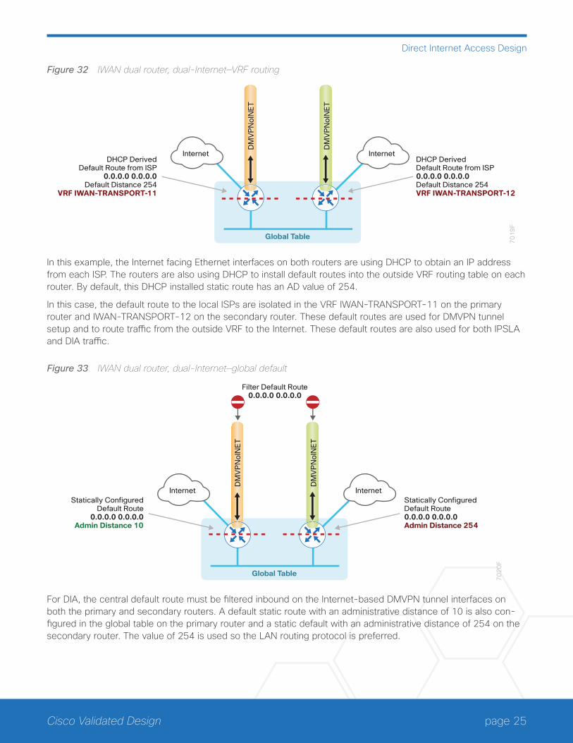
In this example, the Internet facing Ethernet interfaces on both routers are using DHCP to obtain an IP address from each ISP. The routers are also using DHCP to install default routes into the outside VRF routing table on each router. By default, this DHCP installed static route has an AD value of 254.
In this case, the default route to the local ISPs are isolated in the VRF IWAN-TRANSPORT-11 on the primary router and IWAN-TRANSPORT-12 on the secondary router. These default routes are used for DMVPN tunnel setup and to route traffic from the outside VRF to the Internet. These default routes are also used for both IPSLA and DIA traffic.
Figure 33 IWAN dual router, dual-Internet—global default
70
20
F
DM
VP
No
INE
T
DM
VP
No
INE
T
Statically ConfiguredDefault Route0.0.0.0 0.0.0.0Admin Distance 254
Filter Default Route0.0.0.0 0.0.0.0
Statically ConfiguredDefault Route
0.0.0.0 0.0.0.0Admin Distance 10
Global Table
InternetInternet
For DIA, the central default route must be filtered inbound on the Internet-based DMVPN tunnel interfaces on both the primary and secondary routers. A default static route with an administrative distance of 10 is also con-figured in the global table on the primary router and a static default with an administrative distance of 254 on the secondary router. The value of 254 is used so the LAN routing protocol is preferred.
page 26Cisco Validated Design
Direct Internet Access Design
Figure 34 IWAN dual router, dual-Internet—Internet return routing
70
21
F
DM
VP
No
INE
T
DM
VP
No
INE
T
From IWAN-TRANSPORT-12 to Global
Policy Route for 10.0.0.0/8 traffic Set next-hop VRF to Global Table
From IWAN-TRANSPORT-11 to Global
Policy Route for 10.0.0.0/8 traffic Set next-hop VRF to Global Table
Global Table
InternetInternet
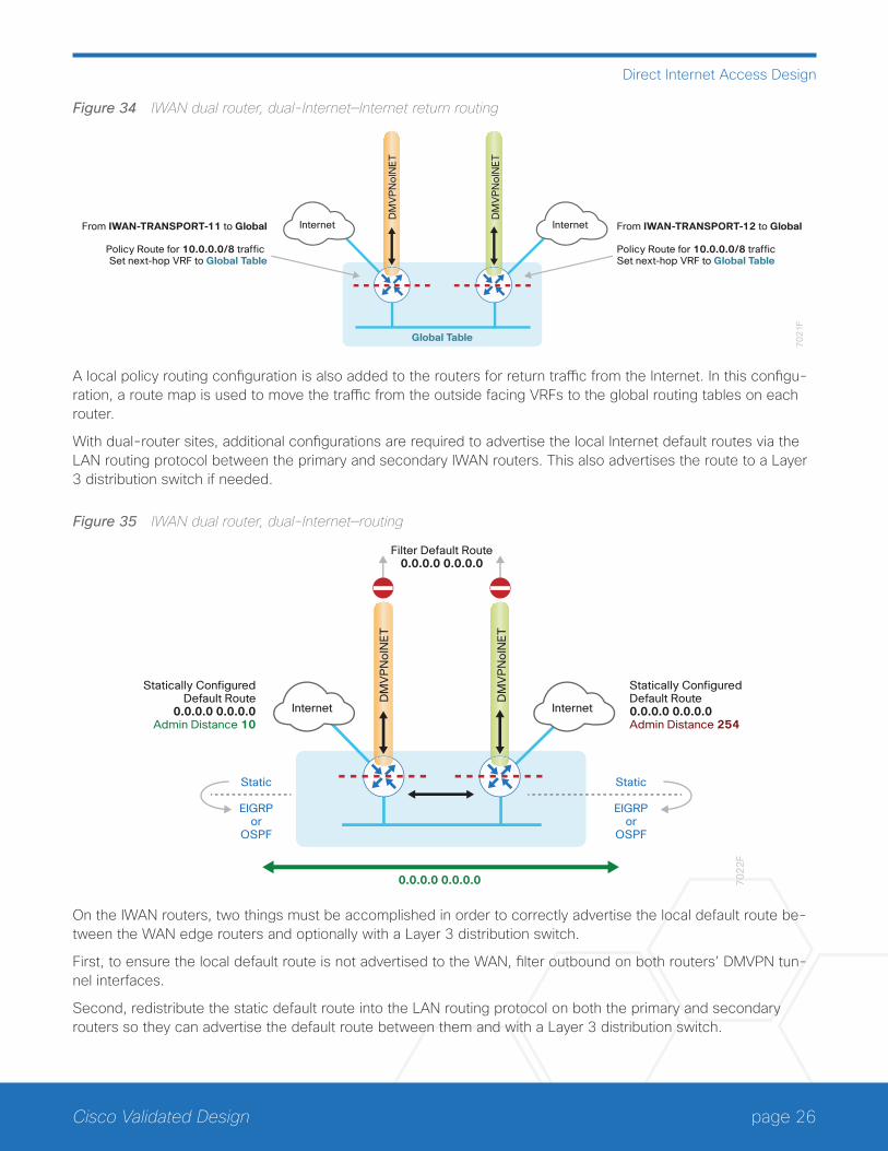
A local policy routing configuration is also added to the routers for return traffic from the Internet. In this configu-ration, a route map is used to move the traffic from the outside facing VRFs to the global routing tables on each router.
With dual-router sites, additional configurations are required to advertise the local Internet default routes via the LAN routing protocol between the primary and secondary IWAN routers. This also advertises the route to a Layer 3 distribution switch if needed.
Figure 35 IWAN dual router, dual-Internet—routingD
MV
PN
oIN
ET
DM
VP
No
INE
T
InternetInternet
70
22
F
Statically ConfiguredDefault Route0.0.0.0 0.0.0.0Admin Distance 254
Statically ConfiguredDefault Route
0.0.0.0 0.0.0.0Admin Distance 10
Filter Default Route0.0.0.0 0.0.0.0
0.0.0.0 0.0.0.0
Static
EIGRPor
OSPF
Static
EIGRPor
OSPF
On the IWAN routers, two things must be accomplished in order to correctly advertise the local default route be-tween the WAN edge routers and optionally with a Layer 3 distribution switch.
First, to ensure the local default route is not advertised to the WAN, filter outbound on both routers’ DMVPN tun-nel interfaces.
Second, redistribute the static default route into the LAN routing protocol on both the primary and secondary routers so they can advertise the default route between them and with a Layer 3 distribution switch.
page 27Cisco Validated Design
Direct Internet Access Design
The primary router advertises the redistributed static default route to the secondary router and distribution switch with an administrative distance of less than 254; this will be preferred over the static default route configured on the secondary router with a distance of 254. The secondary router also advertises a redistributed default static route to the primary router and distribution switch with the less preferred metric.
In this configuration, the DMVPN tunnel on the secondary router can be used as a backup path for Internet if the local Internet connection or the primary router fails. In the case of a primary ISP failure, the secondary router ad-vertises the secondary ISP default via the LAN routing protocol and becomes the Internet path for the remote site network.
DMVPN tunnel state and IPSLA probes are used to determine the availability of the primary router’s local Internet connection. If a failure is detected, an EEM script removes the default static route from the primary router and the redistributed static route on the secondary router is used instead.

page 28Cisco Validated Design
Deploying Direct Internet Access
Deploying Direct Internet Access
This guide uses the following conventions for commands that you enter at the command-line interface (CLI).
Commands to enter at a CLI prompt: configure terminal
Commands that specify a value for a variable: ntp server 10.10.48.17
Commands with variables that you must de�ne: class-map [highest class name]
Commands at a CLI or script prompt: Router# enable
Long commands that line wrap are underlined. Enter them as one command:
police rate 10000 pps burst 10000 packets conform-action
Noteworthy parts of system output (or of device con�guration �les) are highlighted: interface Vlan64 ip address 10.5.204.5 255.255.255.0
How to Read Commands
The successful deployment of secure DIA with IWAN includes a number of components that ensure proper DIA functionality within each remote-site design. All of these tasks are covered in this section:
• Configuration of remote site default routing including any necessary filtering and redistribution
• Configuration of NAT
• Configuration of zone-based firewall
• Configuration of additional router security
• Configuration of ISP black hole routing detection
USING THIS SECTIONThis guide is organized into sections focused on each IWAN remote-site design, with detailed procedures for the implementation of direct Internet access. The configurations in each section are specific to each design model. The common technical details are repeated in each section so it is not necessary to read the entire guide to get a full understanding of the solution.
To configure direct Internet access, use the section appropriate for your remote site design requirements:
• “IWAN Single-Router Hybrid Remote Site with DIA”
• “IWAN Dual-Router Hybrid Remote Site with DIA”
• “IWAN Single-Router Dual-Internet Remote Site with DIA “
• “IWAN Dual-Router Dual-Internet Remote Site with DIA”
page 29Cisco Validated Design
Deploying Direct Internet Access
Reader Tip
The configurations that follow are remote-site configurations only. These configurations assume each remote site has been configured based on the IWAN foundation. For information about con-figuring the remote-site routing and primary site WAN-aggregation routers, see the Intelligent WAN Deployment Guide.
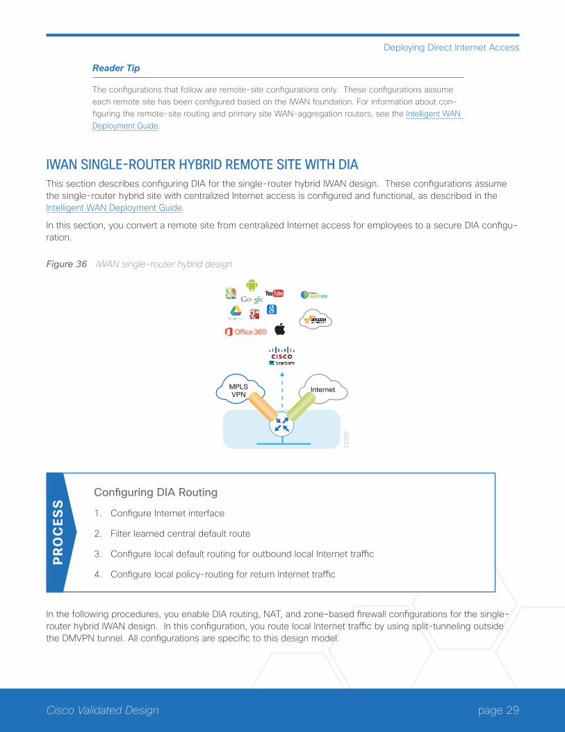
IWAN SINGLE-ROUTER HYBRID REMOTE SITE WITH DIAThis section describes configuring DIA for the single-router hybrid IWAN design. These configurations assume the single-router hybrid site with centralized Internet access is configured and functional, as described in the Intelligent WAN Deployment Guide.
In this section, you convert a remote site from centralized Internet access for employees to a secure DIA configu-ration.
Figure 36 IWAN single-router hybrid design
MPLSVPN
Internet
13
22
F
Ciscowebex
Configuring DIA Routing
1. Configure Internet interface
2. Filter learned central default route
3. Configure local default routing for outbound local Internet traffic
4. Configure local policy-routing for return Internet traffic
PR
OC
ESS
In the following procedures, you enable DIA routing, NAT, and zone-based firewall configurations for the single-router hybrid IWAN design. In this configuration, you route local Internet traffic by using split-tunneling outside the DMVPN tunnel. All configurations are specific to this design model.

page 30Cisco Validated Design
Deploying Direct Internet Access
Procedure 1 Configure Internet interface
For security, disable the ISP interface before configuring DIA. You will not restore this interface until you complete all of the configurations in this section.
Tech Tip
If you are remotely connected to the remote-site router via SSH, you will be disconnected from the router console. Shutting down the Internet interface will drop the existing DMVPN tunnel.
Step 1: Verify that the Internet-facing interface is disabled.
interface GigabitEthernet0/0/1
shutdown
Procedure 2 Filter learned central default route
With DIA routing, the default route is locally configured for the global routing table. It is important to filter the default route originating over the Internet-facing DMVPN tunnel from the central site. Failover to the central site is optional over the MPLS-based DMVPN tunnel. In the single-router hybrid design with DIA, all Internet traffic is routed directly to the local ISP interface; it is not feasible to failover to central Internet by using an Internet based DMVPN tunnel.
Figure 37 Filter inbound default route from the central site
Global Table 70
23
F
Filter Default Route0.0.0.0 0.0.0.0
InternetMPLSVPN
DM
VP
No
INE
T
DM
VP
No
MP
LS
If you are using EIGRP as your routing protocol, choose option 1. If you are using BGP on the WAN and OSPF on the LAN, choose option 2.

page 31Cisco Validated Design
Deploying Direct Internet Access
Option 1: EIGRP on the WAN
Step 1: Create an access list to match the default route and permit all other routes.
ip access-list standard ALL-EXCEPT-DEFAULT
deny 0.0.0.0
permit any
Step 2: Create a route-map to reference the access list.
route-map BLOCK-DEFAULT permit 10
description block only the default route inbound from the WAN
match ip address ALL-EXCEPT-DEFAULT
Step 3: Apply the policy as an inbound distribute list for the Internet-facing DMVPN tunnel interface.
router eigrp IWAN-EIGRP
address-family ipv4 unicast autonomous-system 400
topology base
distribute-list route-map BLOCK-DEFAULT in tunnel11
exit
Step 4: (Optional) If you do not want fallback to centralized Internet, also apply the policy as an inbound distribute list for the MPLS-facing DMVPN tunnel interface.
router eigrp IWAN-EIGRP
address-family ipv4 unicast autonomous-system 400
topology base
distribute-list route-map BLOCK-DEFAULT in tunnel10
exit
Option 2: BGP on the WAN
Step 1: Create an ip prefix-list to match the default route.
ip prefix-list ALL-EXCEPT-DEFAULT seq 10 permit 0.0.0.0/0
Step 2: Create a route-map to reference the ip prefix list.
route-map BLOCK-DEFAULT deny 10
description Block only the default route inbound from the WAN
match ip address prefix-list ALL-EXCEPT-DEFAULT
route-map BLOCK-DEFAULT permit 100
description Permit all other routes
page 32Cisco Validated Design
Deploying Direct Internet Access
Step 3: Apply the policy as an inbound route-map for the Internet-facing DMVPN tunnel interface.
router bgp 65100
address-family ipv4
neighbor INET-HUB route-map BLOCK-DEFAULT in
exit-address-family
Step 4: (Optional) If you do not want fallback to centralized Internet, also apply the policy as an inbound route-map for the MPLS-facing DMVPN tunnel interface.
router bgp 65100
address-family ipv4
neighbor MPLS-HUB route-map BLOCK-DEFAULT in
exit-address-family
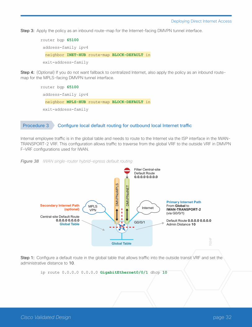
Procedure 3 Configure local default routing for outbound local Internet traffic
Internal employee traffic is in the global table and needs to route to the Internet via the ISP interface in the IWAN-TRANSPORT-2 VRF. This configuration allows traffic to traverse from the global VRF to the outside VRF in DMVPN F-VRF configurations used for IWAN.
Figure 38 IWAN single-router hybrid—egress default routing
Global Table 70
24
F
Filter Central-siteDefault Route0.0.0.0 0.0.0.0
InternetMPLSVPN
DM
VP
No
INE
T
DM
VP
No
MP
LS
Secondary Internet Path(optional)
Central-site Default Route0.0.0.0 0.0.0.0
Global Table
Primary Internet PathFrom Global toIWAN-TRANSPORT-2(via G0/0/1)
Default Route 0.0.0.0 0.0.0.0Admin Distance 10
G0/0/1
Step 1: Configure a default route in the global table that allows traffic into the outside transit VRF and set the administrative distance to 10.
ip route 0.0.0.0 0.0.0.0 GigabitEthernet0/0/1 dhcp 10
page 33Cisco Validated Design
Deploying Direct Internet Access
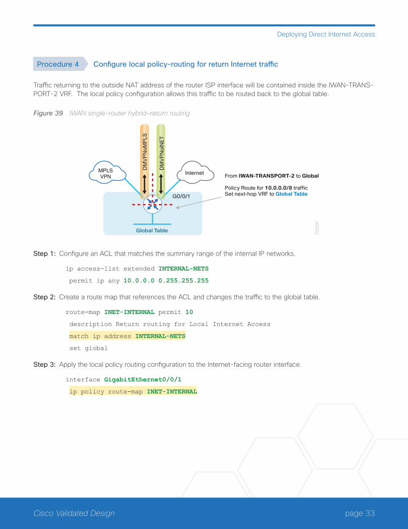
Procedure 4 Configure local policy-routing for return Internet traffic
Traffic returning to the outside NAT address of the router ISP interface will be contained inside the IWAN-TRANS-PORT-2 VRF. The local policy configuration allows this traffic to be routed back to the global table.
Figure 39 IWAN single-router hybrid—return routing
Global Table 70
25
F
InternetMPLSVPN
DM
VP
No
INE
T
DM
VP
No
MP
LS
From IWAN-TRANSPORT-2 to Global
Policy Route for 10.0.0.0/8 traffic Set next-hop VRF to Global Table
G0/0/1
Step 1: Configure an ACL that matches the summary range of the internal IP networks.
ip access-list extended INTERNAL-NETS
permit ip any 10.0.0.0 0.255.255.255
Step 2: Create a route map that references the ACL and changes the traffic to the global table.
route-map INET-INTERNAL permit 10
description Return routing for Local Internet Access
match ip address INTERNAL-NETS
set global
Step 3: Apply the local policy routing configuration to the Internet-facing router interface.
interface GigabitEthernet0/0/1
ip policy route-map INET-INTERNAL
page 34Cisco Validated Design
Deploying Direct Internet Access
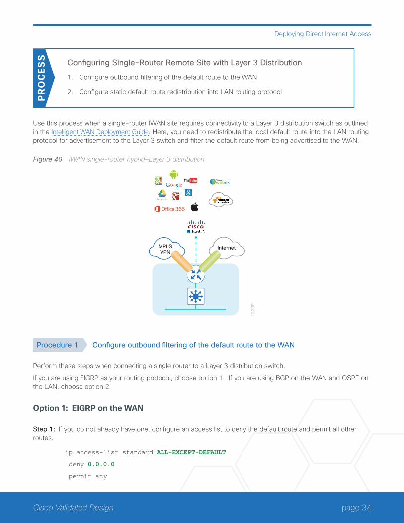
Configuring Single-Router Remote Site with Layer 3 Distribution
1. Configure outbound filtering of the default route to the WAN
2. Configure static default route redistribution into LAN routing protocol
PR
OC
ESS
Use this process when a single-router IWAN site requires connectivity to a Layer 3 distribution switch as outlined in the Intelligent WAN Deployment Guide. Here, you need to redistribute the local default route into the LAN routing protocol for advertisement to the Layer 3 switch and filter the default route from being advertised to the WAN.
Figure 40 IWAN single-router hybrid—Layer 3 distribution
MPLSVPN
Internet1
32
3F
Ciscowebex
Procedure 1 Configure outbound filtering of the default route to the WAN
Perform these steps when connecting a single router to a Layer 3 distribution switch.
If you are using EIGRP as your routing protocol, choose option 1. If you are using BGP on the WAN and OSPF on the LAN, choose option 2.
Option 1: EIGRP on the WAN
Step 1: If you do not already have one, configure an access list to deny the default route and permit all other routes.
ip access-list standard ALL-EXCEPT-DEFAULT
deny 0.0.0.0
permit any
page 35Cisco Validated Design
Deploying Direct Internet Access
Step 2: Add an instance after the existing route map named “ROUTE-LIST” and reference the access list that denies the default route and permits all other routes. There should be an instance of this route map from the IWAN foundation configuration. This statement is added between the existing statements.
route-map ROUTE-LIST permit 20
description Block Local Internet Default route out to the WAN
match ip address ALL-EXCEPT-DEFAULT
Step 3: Ensure that the route map is applied as an outbound distribution list on the DMVPN tunnel interfaces.
router eigrp IWAN-EIGRP
address-family ipv4 unicast autonomous-system 400
topology base
distribute-list route-map ROUTE-LIST out Tunnel10
distribute-list route-map ROUTE-LIST out Tunnel11
exit-af-topology
exit-address-family
Option 2: BGP on the WAN
Step 1: If you do not already have one, create an ip prefix-list to match the default.
ip prefix-list ALL-EXCEPT-DEFAULT seq 10 permit 0.0.0.0/0
Step 2: Add an instance after the existing route map named “SPOKE-OUT” and reference the access list that denies the default route and permits all other routes. There should be an instance of this route map from the IWAN foundation configuration. These statements are added after the existing statements.
route-map SPOKE-OUT deny 20
description Block only the default route outbound from the WAN
match ip address prefix-list ALL-EXCEPT-DEFAULT
route-map SPOKE-OUT permit 1000
description Permit all other routes
Step 3: Ensure the policy is applied as an outbound route-map for the DMVPN tunnel interfaces.
router bgp 65100
address-family ipv4
neighbor MPLS-HUB route-map SPOKE-OUT out
neighbor INET-HUB route-map SPOKE-OUT out
exit-address-family
page 36Cisco Validated Design
Deploying Direct Internet Access
Procedure 2 Configure static default route redistribution into LAN routing protocol
Perform these steps when connecting a single router to a Layer 3 distribution switch.
If you are using EIGRP as your routing protocol, choose option 1. If you are using BGP on the WAN and OSPF on the LAN, choose option 2.
Option 1: EIGRP on the LAN
Step 1: Configure an access list to match the default route for redistribution.
ip access-list standard DEFAULT-ONLY
permit 0.0.0.0
Step 2: Configure a route map for static redistribution, referencing the access list that matches the static default route.
route-map STATIC-IN permit 10
description Redistribute local default route
match ip address DEFAULT-ONLY
Step 3: Redistribute the static default route installed by DHCP into EIGRP AS400 by using the route map.
router eigrp IWAN-EIGRP
address-family ipv4 unicast autonomous-system 400
topology base
redistribute static route-map STATIC-IN
exit-af-topology
exit-address-family
Option 2: BGP on the WAN and OSPF on the LAN
Step 1: Configure an access list to match the default route for redistribution.
ip access-list standard DEFAULT-ONLY
permit 0.0.0.0
Step 2: Create a route-map to reference the ip access-list.
route-map STATIC-IN permit 10
description Redistribute local default route
match ip address DEFAULT-ONLY
page 37Cisco Validated Design
Deploying Direct Internet Access
Step 3: Redistribute the static default route from BGP to OSPF.
router bgp 65100
address-family ipv4
redistribute static route-map STATIC-IN
exit-address-family
Configuring Network Address Translation for DIA
1. Define and configure Cisco IOS NAT policy
PR
OC
ESS
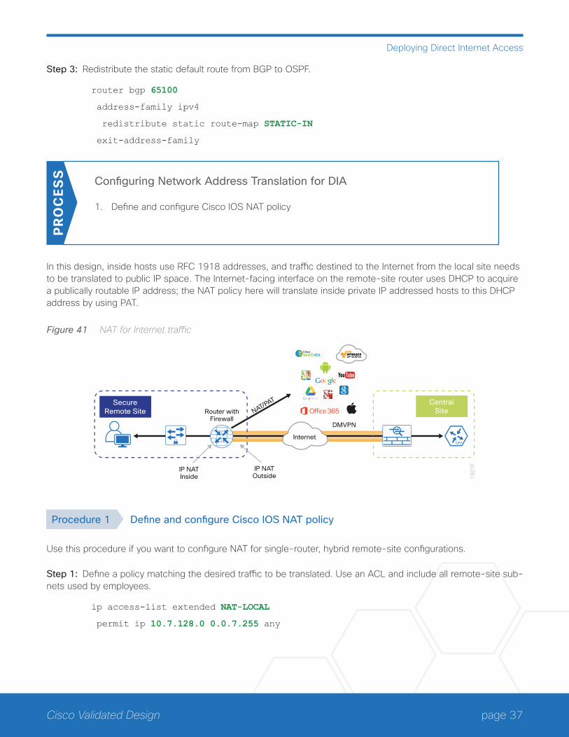
In this design, inside hosts use RFC 1918 addresses, and traffic destined to the Internet from the local site needs to be translated to public IP space. The Internet-facing interface on the remote-site router uses DHCP to acquire a publically routable IP address; the NAT policy here will translate inside private IP addressed hosts to this DHCP address by using PAT.
Figure 41 NAT for Internet traffic
13
01
F
DMVPN
IP NATInside
Router withFirewall
IP NATOutside
CentralSite
SecureRemote Site NAT/PAT
Ciscowebex
Internet
Procedure 1 Define and configure Cisco IOS NAT policy
Use this procedure if you want to configure NAT for single-router, hybrid remote-site configurations.
Step 1: Define a policy matching the desired traffic to be translated. Use an ACL and include all remote-site sub-nets used by employees.
ip access-list extended NAT-LOCAL
permit ip 10.7.128.0 0.0.7.255 any
page 38Cisco Validated Design
Deploying Direct Internet Access
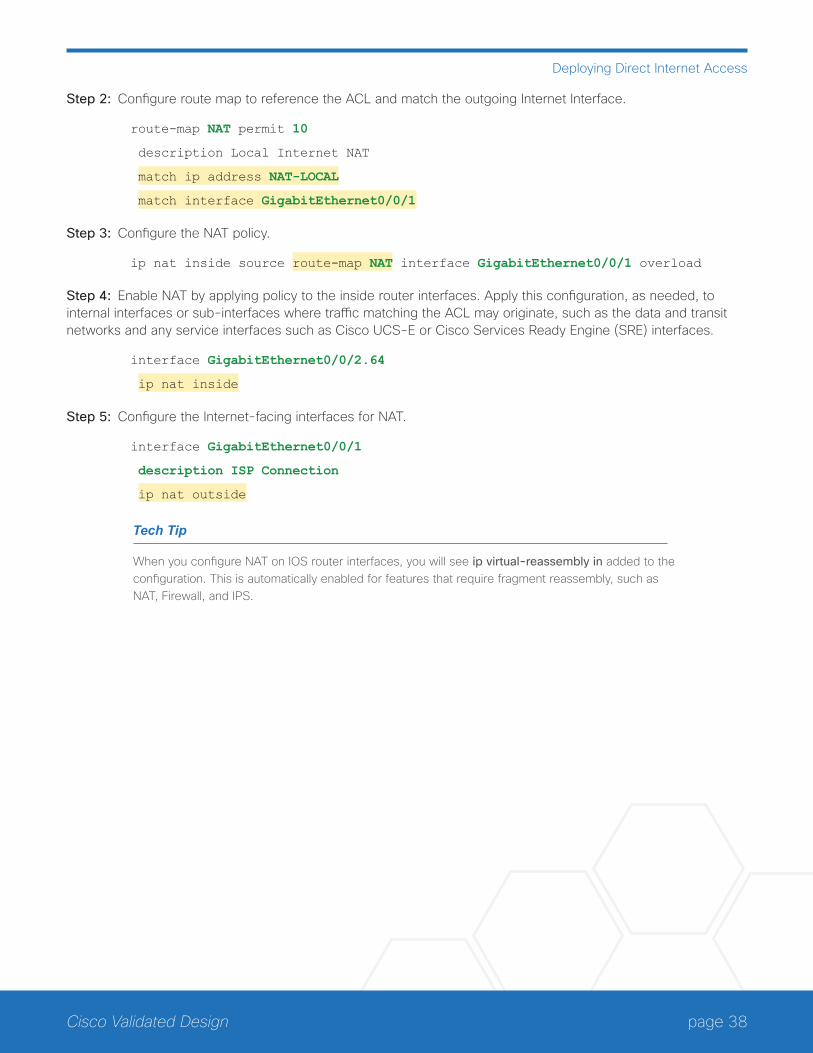
Step 2: Configure route map to reference the ACL and match the outgoing Internet Interface.
route-map NAT permit 10
description Local Internet NAT
match ip address NAT-LOCAL
match interface GigabitEthernet0/0/1
Step 3: Configure the NAT policy.
ip nat inside source route-map NAT interface GigabitEthernet0/0/1 overload
Step 4: Enable NAT by applying policy to the inside router interfaces. Apply this configuration, as needed, to internal interfaces or sub-interfaces where traffic matching the ACL may originate, such as the data and transit networks and any service interfaces such as Cisco UCS-E or Cisco Services Ready Engine (SRE) interfaces.
interface GigabitEthernet0/0/2.64
ip nat inside
Step 5: Configure the Internet-facing interfaces for NAT.
interface GigabitEthernet0/0/1
description ISP Connection
ip nat outside
Tech Tip
When you configure NAT on IOS router interfaces, you will see ip virtual-reassembly in added to the configuration. This is automatically enabled for features that require fragment reassembly, such as NAT, Firewall, and IPS.
page 39Cisco Validated Design
Deploying Direct Internet Access
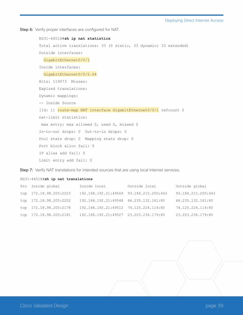
Step 6: Verify proper interfaces are configured for NAT.
RS31-4451X#sh ip nat statistics
Total active translations: 33 (0 static, 33 dynamic; 33 extended)
Outside interfaces:
GigabitEthernet0/0/1
Inside interfaces:
GigabitEthernet0/0/2.64
Hits: 119073 Misses:
Expired translations:
Dynamic mappings:
-- Inside Source
[Id: 1] route-map NAT interface GigabitEthernet0/0/1 refcount 0
nat-limit statistics:
max entry: max allowed 0, used 0, missed 0
In-to-out drops: 0 Out-to-in drops: 0
Pool stats drop: 0 Mapping stats drop: 0
Port block alloc fail: 0
IP alias add fail: 0
Limit entry add fail: 0
Step 7: Verify NAT translations for intended sources that are using local Internet services.
RS31-4451X#sh ip nat translations
Pro Inside global Inside local Outside local Outside global
tcp 172.18.98.205:2223 192.168.192.21:49569 93.184.215.200:443 93.184.215.200:443
tcp 172.18.98.205:2202 192.168.192.21:49548 66.235.132.161:80 66.235.132.161:80
tcp 172.18.98.205:2178 192.168.192.21:49512 74.125.224.114:80 74.125.224.114:80
tcp 172.18.98.205:2181 192.168.192.21:49527 23.203.236.179:80 23.203.236.179:80

page 40Cisco Validated Design
Deploying Direct Internet Access
Configuring Zone-Based Firewall for DIA
1. Configure base Cisco IOS zone-based firewall parameters
2. Restrict traffic to the router
3. Enable and verify zone-based firewall configurationPR
OC
ESS
The following Cisco IOS firewall configuration is intended for use on Internet-facing remote-site routers that pro-vide secure local-Internet access. This configuration assumes DHCP and DMVPN are also configured to use the outside interface. To configure the required base firewall policies, complete the following procedures.
Follow these procedures to secure a remote-site router with direct Internet configurations.
Figure 42 Zone-based firewall for DIA
13
04
F
CentralSite
SecureRemote Site
IOS ZoneFirewall
DMVPN
Security ZoneOUTSIDE
Security ZoneINSIDE
(default)
NAT/PAT
Internet
Ciscowebex
Procedure 1 Configure base Cisco IOS zone-based firewall parameters
Step 1: If it is configured, remove the inbound ACL from the Internet-facing router interfaces, and then shut down the interface before continuing. This prevents unauthorized traffic while the ZBFW is configured.
interface GigabitEthernet0/0/1
shutdown
no ip access-list extended ACL-INET-PUBLIC in

page 41Cisco Validated Design
Deploying Direct Internet Access
Step 2: Define security zones. A zone is a named group of interfaces that have similar functions or security re-quirements. This example defines the names of the two basic security zones identified. For simplicity this design uses the “default” security zone for inside interfaces. Once the default zone has been defined, all interfaces not explicitly configured as members of a security zone will automatically be part of the default security zone.
zone security default
zone security OUTSIDE
Tech Tip
This design uses the “default” zone for all inside interfaces; traffic can flow between all interfaces in the default zone.
An interface not defined as part of a security zone is automatically part of the “default” zone. In this configuration, all undefined interface DMVPN tunnels, transit sub-interfaces, and service interfaces such as Cisco UCS-E, and SRE interfaces are included as part of the default zone.
Be aware that any interface that is removed from a defined security zone will be automatically placed into the default zone. In this configuration, that interface will be treated as an “inside” zone and have access to the internal routing domain.
Step 3: Define a class map to match specific protocols. Class-maps apply match-any or match-all operators in order to determine how to apply the match criteria to the class. If match-any is specified, traffic must meet at least one of the match criteria in the class-map to be included in the class. If match-all is specified, traffic must meet all of the match criteria to be included in the class.
class-map type inspect match-any INSIDE-TO-OUTSIDE-CLASS
match protocol ftp
match protocol tcp
match protocol udp
match protocol icmp
Tech Tip
Protocols that use single ports (such as HTTP, telnet, SSH, etc.) can be statefully allowed with tcp inspection alone by using the match protocol tcp command.
Protocols such as ftp that use multiple ports (one for control and another for data) require application inspection in order to enable dynamic adjustments to the active firewall policy. The specific TCP ports that are required for the application are allowed for short durations, as necessary.
page 42Cisco Validated Design
Deploying Direct Internet Access
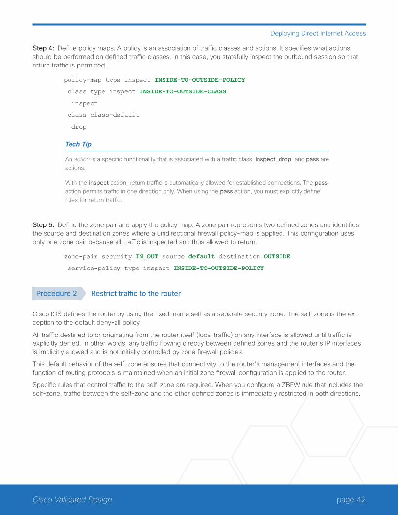
Step 4: Define policy maps. A policy is an association of traffic classes and actions. It specifies what actions should be performed on defined traffic classes. In this case, you statefully inspect the outbound session so that return traffic is permitted.
policy-map type inspect INSIDE-TO-OUTSIDE-POLICY
class type inspect INSIDE-TO-OUTSIDE-CLASS
inspect
class class-default
drop
Tech Tip
An action is a specific functionality that is associated with a traffic class. Inspect, drop, and pass are actions.
With the inspect action, return traffic is automatically allowed for established connections. The pass action permits traffic in one direction only. When using the pass action, you must explicitly define rules for return traffic.
Step 5: Define the zone pair and apply the policy map. A zone pair represents two defined zones and identifies the source and destination zones where a unidirectional firewall policy-map is applied. This configuration uses only one zone pair because all traffic is inspected and thus allowed to return.
zone-pair security IN_OUT source default destination OUTSIDE
service-policy type inspect INSIDE-TO-OUTSIDE-POLICY
Procedure 2 Restrict traffic to the router
Cisco IOS defines the router by using the fixed-name self as a separate security zone. The self-zone is the ex-ception to the default deny-all policy.
All traffic destined to or originating from the router itself (local traffic) on any interface is allowed until traffic is explicitly denied. In other words, any traffic flowing directly between defined zones and the router’s IP interfaces is implicitly allowed and is not initially controlled by zone firewall policies.
This default behavior of the self-zone ensures that connectivity to the router’s management interfaces and the function of routing protocols is maintained when an initial zone firewall configuration is applied to the router.
Specific rules that control traffic to the self-zone are required. When you configure a ZBFW rule that includes the self-zone, traffic between the self-zone and the other defined zones is immediately restricted in both directions.

page 43Cisco Validated Design
Deploying Direct Internet Access
Table 1 Self-zone firewall access list parameters
Protocol Stateful inspection policy
ISAKMP Yes
ICMP Yes
DHCP No
ESP No
GRE No
The following configuration allows the required traffic for proper remote-site router configuration with DMVPN. ESP and DHCP cannot be inspected and need to be configured with a pass action in the policy, using separate ACL and class-maps. ISAKMP should be configured with the inspect action and thus needs to be broken out with a separate ACL and class-maps for inbound and outbound policies.
Tech Tip
More specific ACLs than are shown here with the “any” keyword are recommended for added security.
Step 1: In the following steps, define access lists.
Step 2: Define an ACL allowing traffic with a destination of the router itself from the OUTSIDE zone. This includes ISAKMP for inbound tunnel initiation. This traffic can be inspected and is identified in the following ACL.
ip access-list extended ACL-RTR-IN
permit udp any any eq non500-isakmp
permit udp any any eq isakmp
permit icmp any any echo
permit icmp any any echo-reply
permit icmp any any ttl-exceeded
permit icmp any any port-unreachable
permit udp any any gt 1023 ttl eq 1
Step 3: Identify traffic for IPSEC tunnel initiation and other traffic that will originate from the router (self-zone) to the OUTSIDE zone. This traffic can be inspected.
ip access-list extended ACL-RTR-OUT
permit udp any any eq non500-isakmp
permit udp any any eq isakmp
permit icmp any any
permit udp any any eq domain

page 44Cisco Validated Design
Deploying Direct Internet Access
Tech Tip
The Internet control message protocol (ICMP) and domain entries here are for IPSLA probes that originate from the router.
permit icmp any any
permit udp any any eq domain
Step 4: Configure the DHCP ACL to allow the router to acquire a public IP address dynamically from the ISP. This traffic needs to be defined separately for server and client and cannot be inspected.
ip access-list extended DHCP-IN
permit udp any eq bootps any eq bootpc
ip access-list extended DHCP-OUT
permit udp any eq bootpc any eq bootps
Step 5: Configure the ESP ACL to allow the router to establish IPSEC communications for DMVPN. ESP needs to be explicitly allowed inbound and outbound in separate ACLs. ESP cannot be inspected.
ip access-list extended ESP-IN
permit esp any any
ip access-list extended ESP-OUT
permit esp any any
Step 6: Configure the GRE ACL to allow GRE tunnel formation. GRE needs to be explicitly allowed inbound only.
ip access-list extended GRE-IN
permit gre any any
Tech Tip
GRE needs to be permitted inbound for GRE on IOS-XE platforms due to a difference in interface order of operations. This is not required on IOS ISRG2 platforms.
Next, you define class maps for traffic to and from the self-zone. Separate class-maps are required for inbound and outbound initiated flows as well as for traffic that can be inspected by the router.
Step 7: Define the class-map matching inbound traffic that can be inspected.
class-map type inspect match-any INSPECT-ACL-IN-CLASS
match access-group name ACL-RTR-IN

page 45Cisco Validated Design
Deploying Direct Internet Access
Step 8: Define the class-map matching outbound traffic that can be inspected.
class-map type inspect match-any INSPECT-ACL-OUT-CLASS
match access-group name ACL-RTR-OUT
Step 9: Define the class-map matching inbound traffic that is not able to be inspected.
class-map type inspect match-any PASS-ACL-IN-CLASS
match access-group name ESP-IN
match access-group name DHCP-IN
match access-group name GRE-IN
Step 10: Define the class-map matching outbound traffic that cannot be inspected.
class-map type inspect match-any PASS-ACL-OUT-CLASS
match access-group name ESP-OUT
match access-group name DHCP-OUT
Next, you define policy maps. Create two separate policies, one for traffic inbound and one for traffic outbound.
Step 11: Define the inbound policy-map that refers to both of the outbound class-maps with actions of inspect, pass, and drop for the appropriate class defined.
policy-map type inspect ACL-IN-POLICY
class type inspect INSPECT-ACL-IN-CLASS
inspect
class type inspect PASS-ACL-IN-CLASS
pass
class class-default
drop
Step 12: Define the outbound policy-map that refers to both of the outbound class-maps with actions of inspect, pass, and drop for the appropriate class defined.
policy-map type inspect ACL-OUT-POLICY
class type inspect INSPECT-ACL-OUT-CLASS
inspect
class type inspect PASS-ACL-OUT-CLASS
pass
class class-default
drop
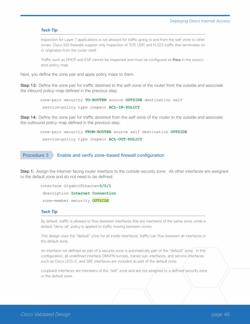
page 46Cisco Validated Design
Deploying Direct Internet Access
Tech Tip
Inspection for Layer 7 applications is not allowed for traffic going to and from the self-zone to other zones. Cisco IOS firewalls support only inspection of TCP, UDP, and H.323 traffic that terminates on or originates from the router itself.
Traffic such as DHCP and ESP cannot be inspected and must be configured as Pass in the associ-ated policy-map.
Next, you define the zone pair and apply policy maps to them.
Step 13: Define the zone pair for traffic destined to the self-zone of the router from the outside and associate the inbound policy-map defined in the previous step.
zone-pair security TO-ROUTER source OUTSIDE destination self
service-policy type inspect ACL-IN-POLICY
Step 14: Define the zone pair for traffic destined from the self-zone of the router to the outside and associate the outbound policy-map defined in the previous step.
zone-pair security FROM-ROUTER source self destination OUTSIDE
service-policy type inspect ACL-OUT-POLICY
Procedure 3 Enable and verify zone-based firewall configuration
Step 1: Assign the Internet-facing router interface to the outside security zone. All other interfaces are assigned to the default zone and do not need to be defined.
interface GigabitEthernet0/0/1
description Internet Connection
zone-member security OUTSIDE
Tech Tip
By default, traffic is allowed to flow between interfaces that are members of the same zone, while a default “deny-all” policy is applied to traffic moving between zones.
This design uses the “default” zone for all inside interfaces; traffic can flow between all interfaces in the default zone.
An interface not defined as part of a security zone is automatically part of the “default” zone. In this configuration, all undefined interface DMVPN tunnels, transit sub-interfaces, and service interfaces such as Cisco UCS-E, and SRE interfaces are included as part of the default zone.
Loopback interfaces are members of the “self” zone and are not assigned to a defined security zone or the default zone.
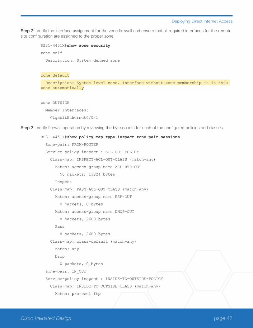
page 47Cisco Validated Design
Deploying Direct Internet Access
Step 2: Verify the interface assignment for the zone firewall and ensure that all required interfaces for the remote site configuration are assigned to the proper zone.
RS31-4451X#show zone security
zone self
Description: System defined zone
zone default
Description: System level zone. Interface without zone membership is in this zone automatically
zone OUTSIDE
Member Interfaces:
GigabitEthernet0/0/1
Step 3: Verify firewall operation by reviewing the byte counts for each of the configured policies and classes.
RS31-4451X#show policy-map type inspect zone-pair sessions
Zone-pair: FROM-ROUTER
Service-policy inspect : ACL-OUT-POLICY
Class-map: INSPECT-ACL-OUT-CLASS (match-any)
Match: access-group name ACL-RTR-OUT
50 packets, 13824 bytes
Inspect
Class-map: PASS-ACL-OUT-CLASS (match-any)
Match: access-group name ESP-OUT
0 packets, 0 bytes
Match: access-group name DHCP-OUT
8 packets, 2680 bytes
Pass
8 packets, 2680 bytes
Class-map: class-default (match-any)
Match: any
Drop
0 packets, 0 bytes
Zone-pair: IN_OUT
Service-policy inspect : INSIDE-TO-OUTSIDE-POLICY
Class-map: INSIDE-TO-OUTSIDE-CLASS (match-any)
Match: protocol ftp
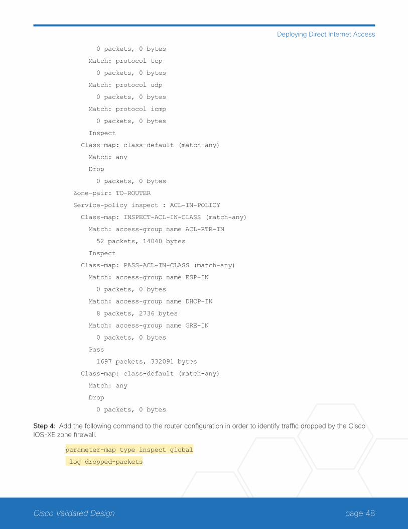
page 48Cisco Validated Design
Deploying Direct Internet Access
0 packets, 0 bytes
Match: protocol tcp
0 packets, 0 bytes
Match: protocol udp
0 packets, 0 bytes
Match: protocol icmp
0 packets, 0 bytes
Inspect
Class-map: class-default (match-any)
Match: any
Drop
0 packets, 0 bytes
Zone-pair: TO-ROUTER
Service-policy inspect : ACL-IN-POLICY
Class-map: INSPECT-ACL-IN-CLASS (match-any)
Match: access-group name ACL-RTR-IN
52 packets, 14040 bytes
Inspect
Class-map: PASS-ACL-IN-CLASS (match-any)
Match: access-group name ESP-IN
0 packets, 0 bytes
Match: access-group name DHCP-IN
8 packets, 2736 bytes
Match: access-group name GRE-IN
0 packets, 0 bytes
Pass
1697 packets, 332091 bytes
Class-map: class-default (match-any)
Match: any
Drop
0 packets, 0 bytes
Step 4: Add the following command to the router configuration in order to identify traffic dropped by the Cisco IOS-XE zone firewall.
parameter-map type inspect global
log dropped-packets
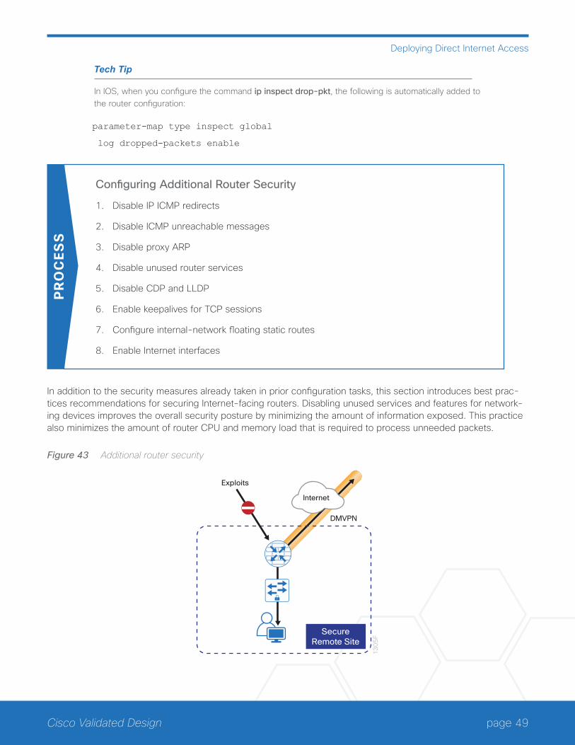
page 49Cisco Validated Design
Deploying Direct Internet Access
Tech Tip
In IOS, when you configure the command ip inspect drop-pkt, the following is automatically added to the router configuration:
parameter-map type inspect global
log dropped-packets enable
Configuring Additional Router Security
1. Disable IP ICMP redirects
2. Disable ICMP unreachable messages
3. Disable proxy ARP
4. Disable unused router services
5. Disable CDP and LLDP
6. Enable keepalives for TCP sessions
7. Configure internal-network floating static routes
8. Enable Internet interfaces
PR
OC
ESS
In addition to the security measures already taken in prior configuration tasks, this section introduces best prac-tices recommendations for securing Internet-facing routers. Disabling unused services and features for network-ing devices improves the overall security posture by minimizing the amount of information exposed. This practice also minimizes the amount of router CPU and memory load that is required to process unneeded packets.
Figure 43 Additional router security
13
05
F
SecureRemote Site
DMVPN
Exploits
Internet

page 50Cisco Validated Design
Deploying Direct Internet Access
Tech Tip
These are general security guidelines only. You may take additional measures to secure remote-site routers on a case-by-case basis. Take care to ensure that the disabling of certain features does not impact other functions of the network. For added security in hybrid IWAN designs, you can also apply these additional security configurations to MPLS provider interfaces.
Procedure 1 Disable IP ICMP redirects
Routers use ICMP redirect messages to notify that a better route is available for a given destination. In this situ-ation, the router forwards the packet and sends an ICMP redirect message back to the sender advising of an alternative and preferred route to the destination. In many implementations, there is no benefit in permitting this behavior. An attacker can generate traffic, forcing the router to respond with ICMP redirect messages, negatively impacting the CPU and performance of the router. You can prevent this by disabling ICMP redirect messages.
Step 1: Disable ICMP redirect messages on Internet-facing router interface.
interface GigabitEthernet0/0/1
description Internet Connection
no ip redirects
Procedure 2 Disable ICMP unreachable messages
When filtering on router interfaces, routers send ICMP unreachable messages back to the source of blocked traf-fic. Generating these messages can increase CPU utilization on the router. By default, Cisco IOS ICMP unreach-able messages are limited to one every 500 milliseconds. ICMP unreachable messages can be disabled on a per interface basis.
Step 1: Disable ICMP unreachable messages on Internet-facing router interface.
interface GigabitEthernet0/0/1
description Internet Connection
no ip unreachables
Procedure 3 Disable proxy ARP
Proxy address resolution protocol (ARP) allows the router to respond to ARP request for hosts other than itself. Proxy ARP can help machines on a subnet reach remote subnets without configuring routing or a default gateway as defined in RFC 1027. Disadvantages to using proxy ARP:
• An attacker can impact available memory by sending a large number of ARP requests.
• A router is also susceptible to man-in-the-middle attacks where a host on the network could be used to spoof the MAC address of the router, resulting in unsuspecting hosts sending traffic to the attacker.

page 51Cisco Validated Design
Deploying Direct Internet Access
You can disable proxy ARP by using the interface configuration command.
Step 1: Disable proxy ARP on Internet-facing router interface.
interface GigabitEthernet0/0/1
description Internet Connection
no ip proxy-arp
Procedure 4 Disable unused router services
As a security best practice, you should disable all unnecessary services that could be used to launch denial of service (DoS) and other attacks. Many unused services that pose a security threat are disabled by default in cur-rent Cisco IOS versions.
Step 1: Disable maintenance operation protocol (MOP) on Internet-facing router interface.
interface GigabitEthernet0/0/1
description Internet Connection
no mop enabled
Step 2: Disable Packet Assembler/Disassembler (PAD) service globally on the router.
no service pad
Step 3: Prevent the router from attempting to locate a configuration file via trivial file transfer protocol (TFTP) globally on the router.
no service config
Procedure 5 Disable CDP and LLDP
Attackers can use Cisco Discovery Protocol (CDP) and link layer discovery protocol (LLDP) for reconnaissance and network mapping. CDP is a network protocol that is used to discover other CDP-enabled devices. CDP is often used by network management systems (NMS) and for troubleshooting networking problems. LLDP is an IEEE protocol that is defined in 802.1AB and is very similar to CDP. You should disable CDP and LLDP on router interfaces that connect to untrusted networks.
Step 1: Disable CDP on Internet-facing router interface.
interface GigabitEthernet0/0/1
description Internet Connection
no cdp enable

page 52Cisco Validated Design
Deploying Direct Internet Access
Step 2: Disable LLDP on Internet-facing router interface.
interface GigabitEthernet0/0/1
description Internet Connection
no lldp transmit
no lldp receive
Procedure 6 Enable keepalives for TCP sessions
This configuration enables TCP keepalives on inbound connections to the router and outbound connections from the router. This ensures that the device on the remote end of the connection is still accessible and half-open or orphaned connections are removed from the router.
Step 1: Enable the TCP keepalives service for inbound and outbound connections globally on the router.
service tcp-keepalives-in
service tcp-keepalives-out
Procedure 7 Configure internal-network floating static routes
In the event the DMVPN tunnel to the hub site fails, you will want to ensure traffic destined to internal networks does not follow the local Internet default route. It’s best to have the network fail closed to prevent possible secu-rity implications and unwanted routing behavior.
Configuring floating static routes to null zero with an AD of 254 ensures that all internal subnets route to null0 in the event of tunnel failure.
Step 1: Configure static route for internal network subnets.
ip route 10.0.0.0 255.0.0.0 null0 254
Tech Tip
Configure the appropriate number of null 0 routes for internal network ranges, using summaries when possible for your specific network environment. Depending on the networking environment more specific statements may be required.
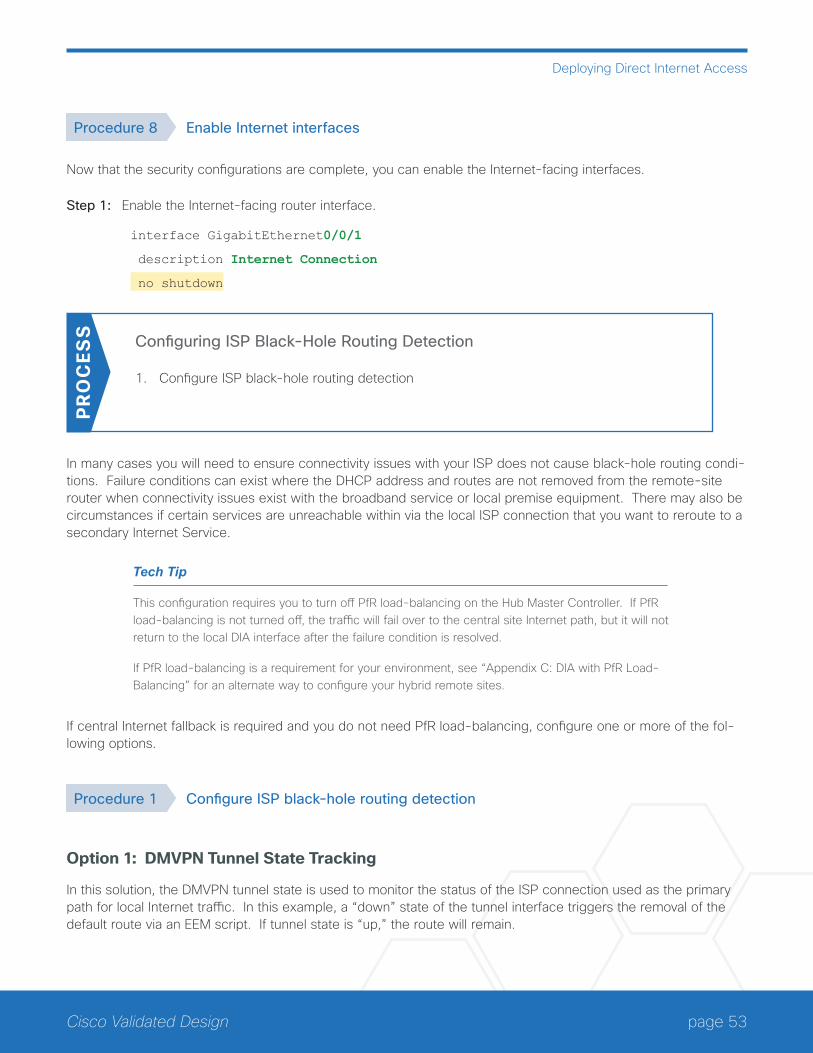
page 53Cisco Validated Design
Deploying Direct Internet Access
Procedure 8 Enable Internet interfaces
Now that the security configurations are complete, you can enable the Internet-facing interfaces.
Step 1: Enable the Internet-facing router interface.
interface GigabitEthernet0/0/1
description Internet Connection
no shutdown
Configuring ISP Black-Hole Routing Detection
1. Configure ISP black-hole routing detection
PR
OC
ESS
In many cases you will need to ensure connectivity issues with your ISP does not cause black-hole routing condi-tions. Failure conditions can exist where the DHCP address and routes are not removed from the remote-site router when connectivity issues exist with the broadband service or local premise equipment. There may also be circumstances if certain services are unreachable within via the local ISP connection that you want to reroute to a secondary Internet Service.
Tech Tip
This configuration requires you to turn off PfR load-balancing on the Hub Master Controller. If PfR load-balancing is not turned off, the traffic will fail over to the central site Internet path, but it will not return to the local DIA interface after the failure condition is resolved.
If PfR load-balancing is a requirement for your environment, see “Appendix C: DIA with PfR Load-Balancing” for an alternate way to configure your hybrid remote sites.
If central Internet fallback is required and you do not need PfR load-balancing, configure one or more of the fol-lowing options.
Procedure 1 Configure ISP black-hole routing detection
Option 1: DMVPN Tunnel State Tracking
In this solution, the DMVPN tunnel state is used to monitor the status of the ISP connection used as the primary path for local Internet traffic. In this example, a “down” state of the tunnel interface triggers the removal of the default route via an EEM script. If tunnel state is “up,” the route will remain.
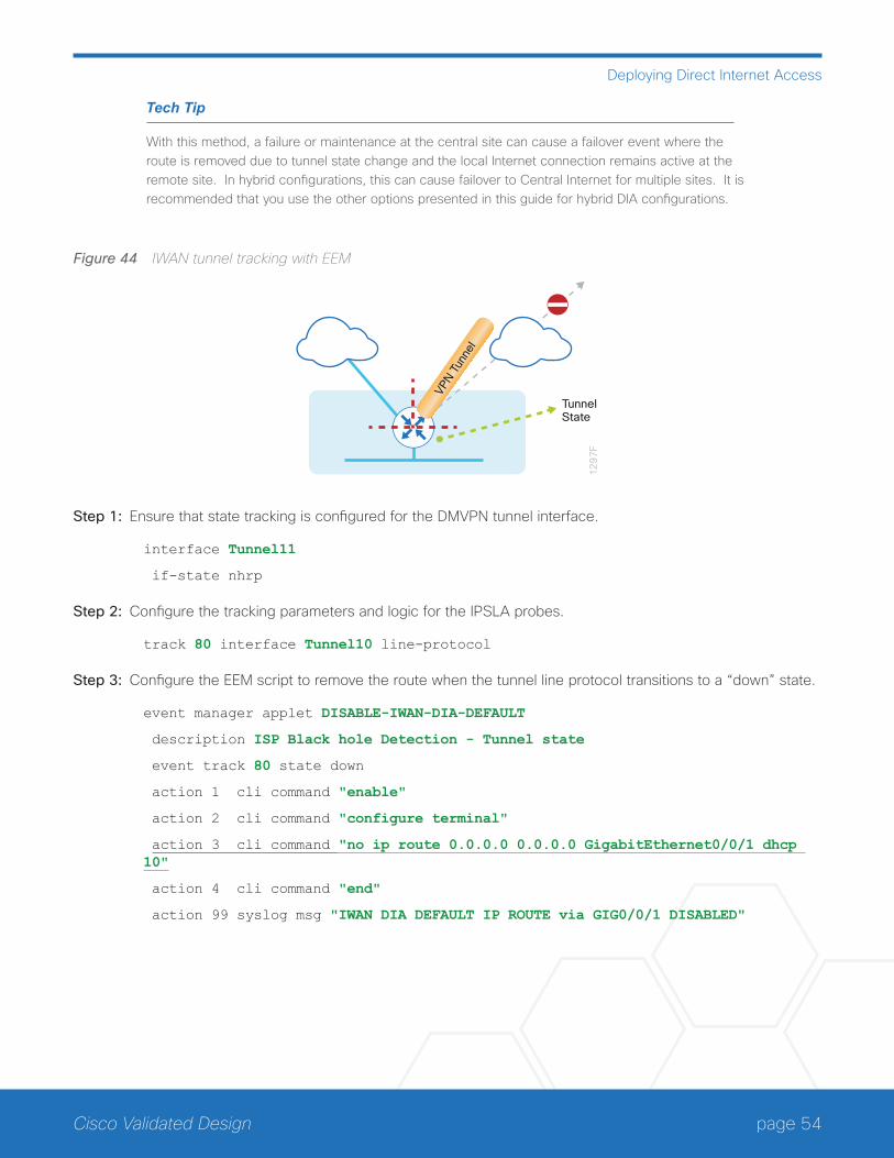
page 54Cisco Validated Design
Deploying Direct Internet Access
Tech Tip
With this method, a failure or maintenance at the central site can cause a failover event where the route is removed due to tunnel state change and the local Internet connection remains active at the remote site. In hybrid configurations, this can cause failover to Central Internet for multiple sites. It is recommended that you use the other options presented in this guide for hybrid DIA configurations.
Figure 44 IWAN tunnel tracking with EEM
12
97
F
VPN T
unne
l
TunnelState
Step 1: Ensure that state tracking is configured for the DMVPN tunnel interface.
interface Tunnel11
if-state nhrp
Step 2: Configure the tracking parameters and logic for the IPSLA probes.
track 80 interface Tunnel10 line-protocol
Step 3: Configure the EEM script to remove the route when the tunnel line protocol transitions to a “down” state.
event manager applet DISABLE-IWAN-DIA-DEFAULT
description ISP Black hole Detection - Tunnel state
event track 80 state down
action 1 cli command "enable"
action 2 cli command "configure terminal"
action 3 cli command "no ip route 0.0.0.0 0.0.0.0 GigabitEthernet0/0/1 dhcp 10"
action 4 cli command "end"
action 99 syslog msg "IWAN DIA DEFAULT IP ROUTE via GIG0/0/1 DISABLED"
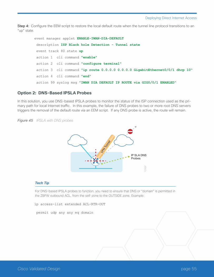
page 55Cisco Validated Design
Deploying Direct Internet Access
Step 4: Configure the EEM script to restore the local default route when the tunnel line protocol transitions to an “up” state.
event manager applet ENABLE-IWAN-DIA-DEFAULT
description ISP Black hole Detection - Tunnel state
event track 80 state up
action 1 cli command "enable"
action 2 cli command "configure terminal"
action 3 cli command "ip route 0.0.0.0 0.0.0.0 GigabitEthernet0/0/1 dhcp 10"
action 4 cli command "end"
action 99 syslog msg "IWAN DIA DEFAULT IP ROUTE via GIG0/0/1 ENABLED"
Option 2: DNS-Based IPSLA Probes
In this solution, you use DNS-based IPSLA probes to monitor the status of the ISP connection used as the pri-mary path for local Internet traffic. In this example, the failure of DNS probes to two or more root DNS servers triggers the removal of the default route via an EEM script. If any DNS probe is active, the route will remain.
Figure 45 IPSLA with DNS probes
12
99
F
VPN T
unne
l
IP SLA DNSProbes
Tech Tip
For DNS-based IPSLA probes to function, you need to ensure that DNS or “domain” is permitted in the ZBFW outbound ACL, from the self-zone to the OUTSIDE zone. Example:
ip access-list extended ACL-RTR-OUT
permit udp any any eq domain
page 56Cisco Validated Design
Deploying Direct Internet Access
Step 1: Configure the VRF-aware IPSLA DNS probes.
ip sla 118
dns d.root-servers.net name-server 199.7.91.13
vrf IWAN-TRANSPORT-2
threshold 1000
timeout 3000
frequency 15
ip sla schedule 118 life forever start-time now
ip sla 119
dns b.root-servers.net name-server 192.228.79.201
vrf IWAN-TRANSPORT-2
threshold 1000
timeout 3000
frequency 15
ip sla schedule 119 life forever start-time now
Tech Tip
When configuring DNS probes, you should specify the hostname of the DNS server itself. That asks the DNS server to resolve for itself, allowing the use of root DNS servers.
Step 2: Configure the tracking parameters and logic for the IPSLA probes.
track 73 ip sla 118 reachability
track 74 ip sla 119 reachability
track 100 list boolean or
object 73
object 74
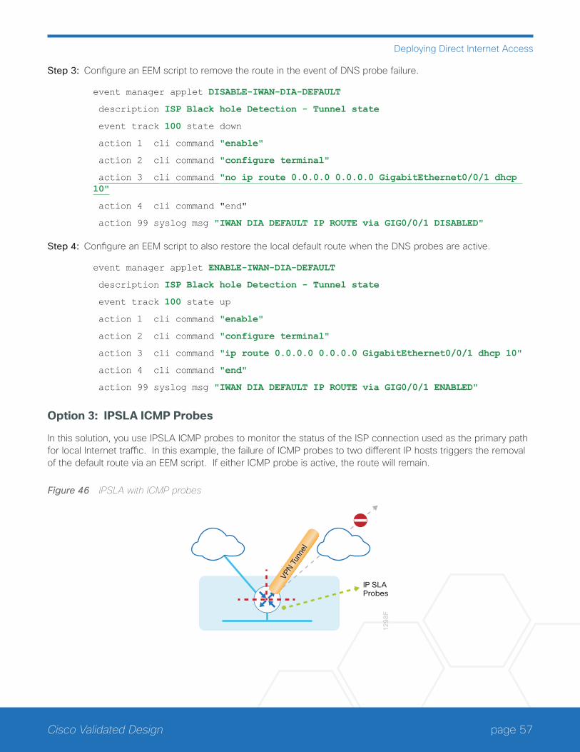
page 57Cisco Validated Design
Deploying Direct Internet Access
Step 3: Configure an EEM script to remove the route in the event of DNS probe failure.
event manager applet DISABLE-IWAN-DIA-DEFAULT
description ISP Black hole Detection - Tunnel state
event track 100 state down
action 1 cli command "enable"
action 2 cli command "configure terminal"
action 3 cli command "no ip route 0.0.0.0 0.0.0.0 GigabitEthernet0/0/1 dhcp 10"
action 4 cli command "end"
action 99 syslog msg "IWAN DIA DEFAULT IP ROUTE via GIG0/0/1 DISABLED"
Step 4: Configure an EEM script to also restore the local default route when the DNS probes are active.
event manager applet ENABLE-IWAN-DIA-DEFAULT
description ISP Black hole Detection - Tunnel state
event track 100 state up
action 1 cli command "enable"
action 2 cli command "configure terminal"
action 3 cli command "ip route 0.0.0.0 0.0.0.0 GigabitEthernet0/0/1 dhcp 10"
action 4 cli command "end"
action 99 syslog msg "IWAN DIA DEFAULT IP ROUTE via GIG0/0/1 ENABLED"
Option 3: IPSLA ICMP Probes
In this solution, you use IPSLA ICMP probes to monitor the status of the ISP connection used as the primary path for local Internet traffic. In this example, the failure of ICMP probes to two different IP hosts triggers the removal of the default route via an EEM script. If either ICMP probe is active, the route will remain.
Figure 46 IPSLA with ICMP probes
12
98
F
VPN T
unne
l
IP SLAProbes
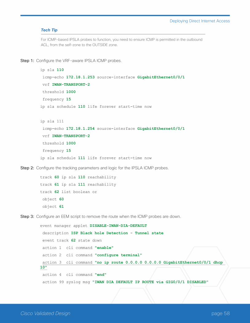
page 58Cisco Validated Design
Deploying Direct Internet Access
Tech Tip
For ICMP-based IPSLA probes to function, you need to ensure ICMP is permitted in the outbound ACL, from the self-zone to the OUTSIDE zone.
Step 1: Configure the VRF-aware IPSLA ICMP probes.
ip sla 110
icmp-echo 172.18.1.253 source-interface GigabitEthernet0/0/1
vrf IWAN-TRANSPORT-2
threshold 1000
frequency 15
ip sla schedule 110 life forever start-time now
ip sla 111
icmp-echo 172.18.1.254 source-interface GigabitEthernet0/0/1
vrf IWAN-TRANSPORT-2
threshold 1000
frequency 15
ip sla schedule 111 life forever start-time now
Step 2: Configure the tracking parameters and logic for the IPSLA ICMP probes.
track 60 ip sla 110 reachability
track 61 ip sla 111 reachability
track 62 list boolean or
object 60
object 61
Step 3: Configure an EEM script to remove the route when the ICMP probes are down.
event manager applet DISABLE-IWAN-DIA-DEFAULT
description ISP Black hole Detection - Tunnel state
event track 62 state down
action 1 cli command "enable"
action 2 cli command "configure terminal"
action 3 cli command "no ip route 0.0.0.0 0.0.0.0 GigabitEthernet0/0/1 dhcp 10"
action 4 cli command "end"
action 99 syslog msg "IWAN DIA DEFAULT IP ROUTE via GIG0/0/1 DISABLED"

page 59Cisco Validated Design
Deploying Direct Internet Access
Step 4: Configure the EEM script to also restore the local default route when the ICMP probes are active.
event manager applet ENABLE-IWAN-DIA-DEFAULT
description ISP Black hole Detection - Tunnel state
event track 62 state up
action 1 cli command "enable"
action 2 cli command "configure terminal"
action 3 cli command "ip route 0.0.0.0 0.0.0.0 GigabitEthernet0/0/1 dhcp 10"
action 4 cli command "end"
action 99 syslog msg "IWAN DIA DEFAULT IP ROUTE via GIG0/0/1 ENABLED"
IWAN DUAL-ROUTER HYBRID REMOTE SITE WITH DIAThis section describes configuring of DIA for the dual-router hybrid IWAN design. These configurations assume the dual-router hybrid site with centralized Internet access is configured and functional, as outlined in the Intel-ligent WAN Deployment Guide.
In this section, you convert a remote site from centralized Internet access for employees to a secure DIA configu-ration.
Figure 47 IWAN dual-router hybrid with DIA
13
24
F
InternetMPLSVPN
Ciscowebex
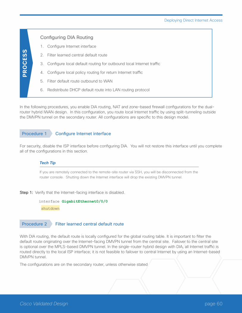
page 60Cisco Validated Design
Deploying Direct Internet Access
Configuring DIA Routing
1. Configure Internet interface
2. Filter learned central default route
3. Configure local default routing for outbound local Internet traffic
4. Configure local policy routing for return Internet traffic
5. Filter default route outbound to WAN
6. Redistribute DHCP default route into LAN routing protocol
PR
OC
ESS
In the following procedures, you enable DIA routing, NAT and zone-based firewall configurations for the dual-router hybrid IWAN design. In this configuration, you route local Internet traffic by using split-tunneling outside the DMVPN tunnel on the secondary router. All configurations are specific to this design model.
Procedure 1 Configure Internet interface
For security, disable the ISP interface before configuring DIA. You will not restore this interface until you complete all of the configurations in this section.
Tech Tip
If you are remotely connected to the remote-site router via SSH, you will be disconnected from the router console. Shutting down the Internet interface will drop the existing DMVPN tunnel.
Step 1: Verify that the Internet-facing interface is disabled.
interface GigabitEthernet0/0/0
shutdown
Procedure 2 Filter learned central default route
With DIA routing, the default route is locally configured for the global routing table. It is important to filter the default route originating over the Internet-facing DMVPN tunnel from the central site. Failover to the central site is optional over the MPLS-based DMVPN tunnel. In the single-router hybrid design with DIA, all Internet traffic is routed directly to the local ISP interface; it is not feasible to failover to central Internet by using an Internet-based DMVPN tunnel.
The configurations are on the secondary router, unless otherwise stated

page 61Cisco Validated Design
Deploying Direct Internet Access
Figure 48 Filter inbound default route from the central site
70
26
F
DM
VP
No
INE
T
DM
VP
No
MP
LS
Global Table
InternetMPLS
Filter Default Route0.0.0.0 0.0.0.0
If you are using EIGRP as your routing protocol, choose option 1. If you are using BGP on the WAN and OSPF on the LAN, choose option 2.
Option 1: EIGRP on the WAN
Step 1: Create an access list to match the default route and permit all other routes.
ip access-list standard ALL-EXCEPT-DEFAULT
deny 0.0.0.0
permit any
Step 2: Create a route-map to reference the access list.
route-map BLOCK-DEFAULT permit 10
description Block only the default route inbound from the WAN
match ip address ALL-EXCEPT-DEFAULT
Step 3: Apply the policy as an inbound distribute list for the Internet-facing DMVPN tunnel interface.
router eigrp IWAN-EIGRP
address-family ipv4 unicast autonomous-system 400
topology base
distribute-list route-map BLOCK-DEFAULT in tunnel11
exit
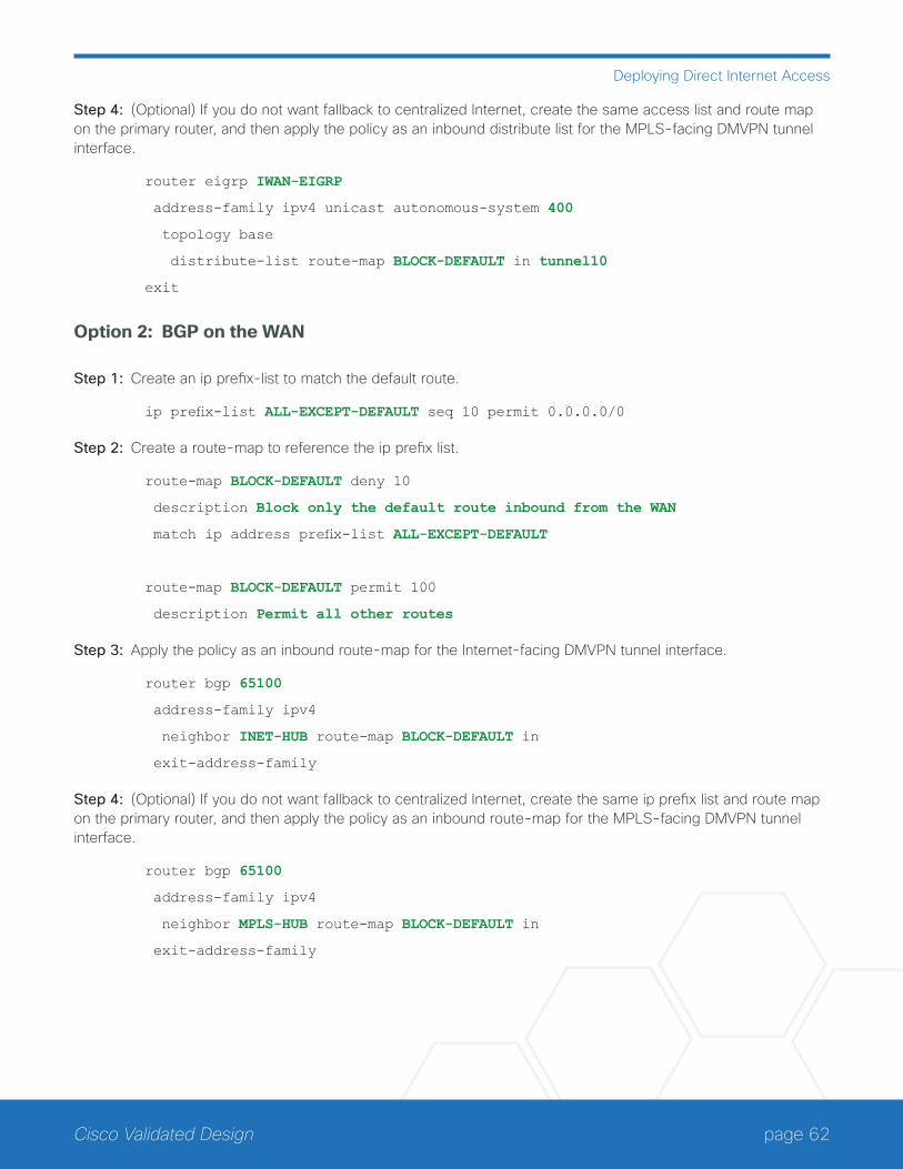
page 62Cisco Validated Design
Deploying Direct Internet Access
Step 4: (Optional) If you do not want fallback to centralized Internet, create the same access list and route map on the primary router, and then apply the policy as an inbound distribute list for the MPLS-facing DMVPN tunnel interface.
router eigrp IWAN-EIGRP
address-family ipv4 unicast autonomous-system 400
topology base
distribute-list route-map BLOCK-DEFAULT in tunnel10
exit
Option 2: BGP on the WAN
Step 1: Create an ip prefix-list to match the default route.
ip prefix-list ALL-EXCEPT-DEFAULT seq 10 permit 0.0.0.0/0
Step 2: Create a route-map to reference the ip prefix list.
route-map BLOCK-DEFAULT deny 10
description Block only the default route inbound from the WAN
match ip address prefix-list ALL-EXCEPT-DEFAULT
route-map BLOCK-DEFAULT permit 100
description Permit all other routes
Step 3: Apply the policy as an inbound route-map for the Internet-facing DMVPN tunnel interface.
router bgp 65100
address-family ipv4
neighbor INET-HUB route-map BLOCK-DEFAULT in
exit-address-family
Step 4: (Optional) If you do not want fallback to centralized Internet, create the same ip prefix list and route map on the primary router, and then apply the policy as an inbound route-map for the MPLS-facing DMVPN tunnel interface.
router bgp 65100
address-family ipv4
neighbor MPLS-HUB route-map BLOCK-DEFAULT in
exit-address-family
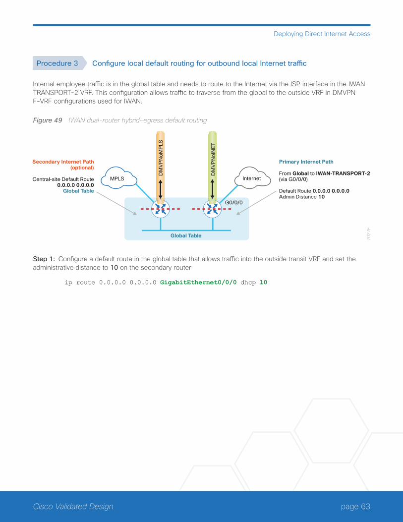
page 63Cisco Validated Design
Deploying Direct Internet Access
Procedure 3 Configure local default routing for outbound local Internet traffic
Internal employee traffic is in the global table and needs to route to the Internet via the ISP interface in the IWAN-TRANSPORT-2 VRF. This configuration allows traffic to traverse from the global to the outside VRF in DMVPN F-VRF configurations used for IWAN.
Figure 49 IWAN dual-router hybrid—egress default routing
70
27
F
DM
VP
No
INE
T
DM
VP
No
MP
LS
Global Table
InternetMPLS
Secondary Internet Path(optional)
Central-site Default Route0.0.0.0 0.0.0.0
Global Table
Primary Internet Path
From Global to IWAN-TRANSPORT-2(via G0/0/0)
Default Route 0.0.0.0 0.0.0.0Admin Distance 10
G0/0/0
Step 1: Configure a default route in the global table that allows traffic into the outside transit VRF and set the administrative distance to 10 on the secondary router
ip route 0.0.0.0 0.0.0.0 GigabitEthernet0/0/0 dhcp 10
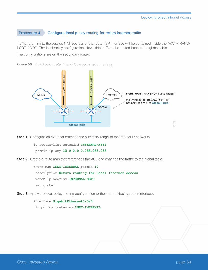
page 64Cisco Validated Design
Deploying Direct Internet Access
Procedure 4 Configure local policy routing for return Internet traffic
Traffic returning to the outside NAT address of the router ISP interface will be contained inside the IWAN-TRANS-PORT-2 VRF. The local policy configuration allows this traffic to be routed back to the global table.
The configurations are on the secondary router.
Figure 50 IWAN dual-router hybrid—local policy return routing
70
28
F
DM
VP
No
INE
T
DM
VP
No
MP
LS
Global Table
InternetMPLS From IWAN-TRANSPORT-2 to Global
Policy Route for 10.0.0.0/8 traffic Set next-hop VRF to Global Table
G0/0/0
Step 1: Configure an ACL that matches the summary range of the internal IP networks.
ip access-list extended INTERNAL-NETS
permit ip any 10.0.0.0 0.255.255.255
Step 2: Create a route map that references the ACL and changes the traffic to the global table.
route-map INET-INTERNAL permit 10
description Return routing for Local Internet Access
match ip address INTERNAL-NETS
set global
Step 3: Apply the local policy routing configuration to the Internet-facing router interface.
interface GigabitEthernet0/0/0
ip policy route-map INET-INTERNAL
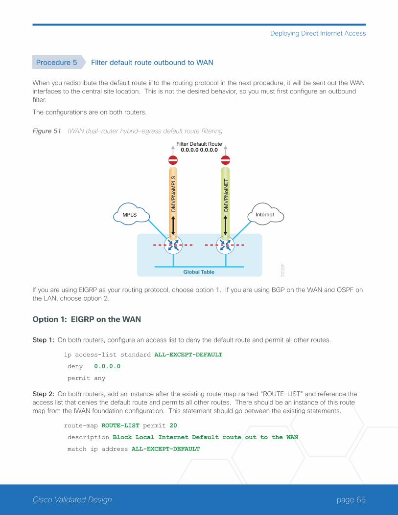
page 65Cisco Validated Design
Deploying Direct Internet Access
Procedure 5 Filter default route outbound to WAN
When you redistribute the default route into the routing protocol in the next procedure, it will be sent out the WAN interfaces to the central site location. This is not the desired behavior, so you must first configure an outbound filter.
The configurations are on both routers.
Figure 51 IWAN dual-router hybrid—egress default route filtering
70
29
F
DM
VP
No
INE
T
DM
VP
No
MP
LS
Global Table
InternetMPLS
Filter Default Route0.0.0.0 0.0.0.0
If you are using EIGRP as your routing protocol, choose option 1. If you are using BGP on the WAN and OSPF on the LAN, choose option 2.
Option 1: EIGRP on the WAN
Step 1: On both routers, configure an access list to deny the default route and permit all other routes.
ip access-list standard ALL-EXCEPT-DEFAULT
deny 0.0.0.0
permit any
Step 2: On both routers, add an instance after the existing route map named “ROUTE-LIST” and reference the access list that denies the default route and permits all other routes. There should be an instance of this route map from the IWAN foundation configuration. This statement should go between the existing statements.
route-map ROUTE-LIST permit 20
description Block Local Internet Default route out to the WAN
match ip address ALL-EXCEPT-DEFAULT
page 66Cisco Validated Design
Deploying Direct Internet Access
Step 3: On the primary router, ensure that the route map is applied as an outbound distribution list on the DMVPN tunnel interface. Apply this as part of the foundational configuration for dual-router egress filtering.
router eigrp IWAN-EIGRP
address-family ipv4 unicast autonomous-system 400
topology base
distribute-list route-map ROUTE-LIST out Tunnel10
exit-af-topology
exit-address-family
Step 4: On the secondary router, ensure that the route map is applied as an outbound distribution list on the DM-VPN tunnel interface. Apply this as part of the foundational configuration for dual-router egress filtering.
router eigrp IWAN-EIGRP
address-family ipv4 unicast autonomous-system 400
topology base
distribute-list route-map ROUTE-LIST out Tunnel11
exit-af-topology
exit-address-family
Option 2: BGP on the WAN
Step 1: On both routers, create an ip prefix-list to match the default.
ip prefix-list ALL-EXCEPT-DEFAULT seq 10 permit 0.0.0.0/0
Step 2: On both routers, add an instance after the existing route map named “SPOKE-OUT” and reference the access list that denies the default route and permits all other routes. There should be an instance of this route map from the IWAN foundation configuration. These statements are added after the existing statements.
route-map SPOKE-OUT deny 20
description Block only the default route outbound from the WAN
match ip address prefix-list ALL-EXCEPT-DEFAULT
route-map SPOKE-OUT permit 1000
description Permit all other routes
Step 3: On the primary router, ensure the policy is applied as an outbound route-map for the DMVPN tunnel interface. Apply this as part of the foundational configuration for dual-router egress filtering.
router bgp 65100
address-family ipv4
neighbor MPLS-HUB route-map SPOKE-OUT out
exit-address-family
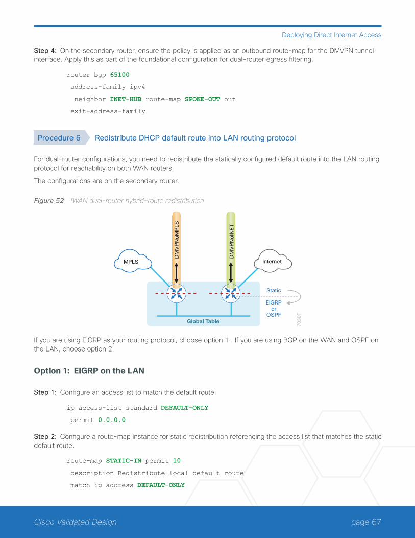
page 67Cisco Validated Design
Deploying Direct Internet Access
Step 4: On the secondary router, ensure the policy is applied as an outbound route-map for the DMVPN tunnel interface. Apply this as part of the foundational configuration for dual-router egress filtering.
router bgp 65100
address-family ipv4
neighbor INET-HUB route-map SPOKE-OUT out
exit-address-family
Procedure 6 Redistribute DHCP default route into LAN routing protocol
For dual-router configurations, you need to redistribute the statically configured default route into the LAN routing protocol for reachability on both WAN routers.
The configurations are on the secondary router.
Figure 52 IWAN dual-router hybrid—route redistribution
70
30
F
DM
VP
No
INE
T
DM
VP
No
MP
LS
Global Table
InternetMPLS
Static
EIGRPor
OSPF
If you are using EIGRP as your routing protocol, choose option 1. If you are using BGP on the WAN and OSPF on the LAN, choose option 2.
Option 1: EIGRP on the LAN
Step 1: Configure an access list to match the default route.
ip access-list standard DEFAULT-ONLY
permit 0.0.0.0
Step 2: Configure a route-map instance for static redistribution referencing the access list that matches the static default route.
route-map STATIC-IN permit 10
description Redistribute local default route
match ip address DEFAULT-ONLY
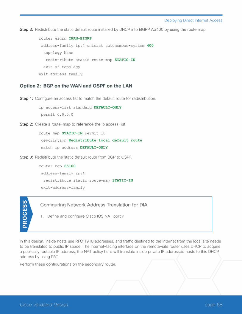
page 68Cisco Validated Design
Deploying Direct Internet Access
Step 3: Redistribute the static default route installed by DHCP into EIGRP AS400 by using the route map.
router eigrp IWAN-EIGRP
address-family ipv4 unicast autonomous-system 400
topology base
redistribute static route-map STATIC-IN
exit-af-topology
exit-address-family
Option 2: BGP on the WAN and OSPF on the LAN
Step 1: Configure an access list to match the default route for redistribution.
ip access-list standard DEFAULT-ONLY
permit 0.0.0.0
Step 2: Create a route-map to reference the ip access-list.
route-map STATIC-IN permit 10
description Redistribute local default route
match ip address DEFAULT-ONLY
Step 3: Redistribute the static default route from BGP to OSPF.
router bgp 65100
address-family ipv4
redistribute static route-map STATIC-IN
exit-address-family
Configuring Network Address Translation for DIA
1. Define and configure Cisco IOS NAT policy
PR
OC
ESS
In this design, inside hosts use RFC 1918 addresses, and traffic destined to the Internet from the local site needs to be translated to public IP space. The Internet-facing interface on the remote-site router uses DHCP to acquire a publically routable IP address; the NAT policy here will translate inside private IP addressed hosts to this DHCP address by using PAT.
Perform these configurations on the secondary router.
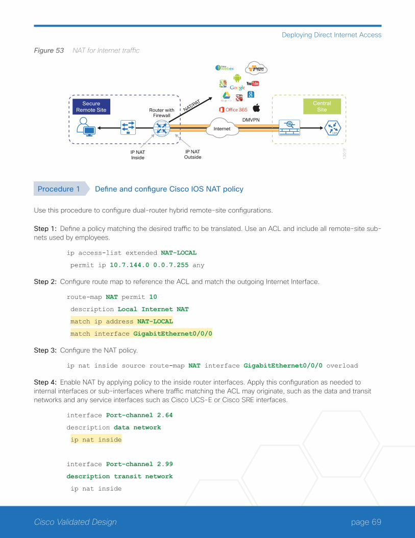
page 69Cisco Validated Design
Deploying Direct Internet Access
Figure 53 NAT for Internet traffic
13
01
F
DMVPN
IP NATInside
Router withFirewall
IP NATOutside
CentralSite
SecureRemote Site NAT/PAT
Ciscowebex
Internet
Procedure 1 Define and configure Cisco IOS NAT policy
Use this procedure to configure dual-router hybrid remote-site configurations.
Step 1: Define a policy matching the desired traffic to be translated. Use an ACL and include all remote-site sub-nets used by employees.
ip access-list extended NAT-LOCAL
permit ip 10.7.144.0 0.0.7.255 any
Step 2: Configure route map to reference the ACL and match the outgoing Internet Interface.
route-map NAT permit 10
description Local Internet NAT
match ip address NAT-LOCAL
match interface GigabitEthernet0/0/0
Step 3: Configure the NAT policy.
ip nat inside source route-map NAT interface GigabitEthernet0/0/0 overload
Step 4: Enable NAT by applying policy to the inside router interfaces. Apply this configuration as needed to internal interfaces or sub-interfaces where traffic matching the ACL may originate, such as the data and transit networks and any service interfaces such as Cisco UCS-E or Cisco SRE interfaces.
interface Port-channel 2.64
description data network
ip nat inside
interface Port-channel 2.99
description transit network
ip nat inside
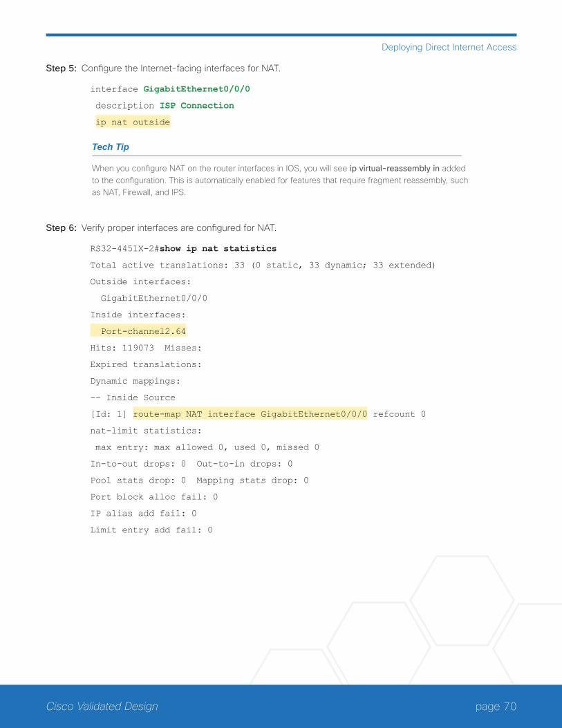
page 70Cisco Validated Design
Deploying Direct Internet Access
Step 5: Configure the Internet-facing interfaces for NAT.
interface GigabitEthernet0/0/0
description ISP Connection
ip nat outside
Tech Tip
When you configure NAT on the router interfaces in IOS, you will see ip virtual-reassembly in added to the configuration. This is automatically enabled for features that require fragment reassembly, such as NAT, Firewall, and IPS.
Step 6: Verify proper interfaces are configured for NAT.
RS32-4451X-2#show ip nat statistics
Total active translations: 33 (0 static, 33 dynamic; 33 extended)
Outside interfaces:
GigabitEthernet0/0/0
Inside interfaces:
Port-channel2.64
Hits: 119073 Misses:
Expired translations:
Dynamic mappings:
-- Inside Source
[Id: 1] route-map NAT interface GigabitEthernet0/0/0 refcount 0
nat-limit statistics:
max entry: max allowed 0, used 0, missed 0
In-to-out drops: 0 Out-to-in drops: 0
Pool stats drop: 0 Mapping stats drop: 0
Port block alloc fail: 0
IP alias add fail: 0
Limit entry add fail: 0

page 71Cisco Validated Design
Deploying Direct Internet Access
Step 7: Verify NAT translations for intended sources that are using local Internet services.
RS32-4451X-2#sh ip nat translations
Pro Inside global Inside local Outside local Outside global
tcp 172.18.98.250:2223 192.168.192.21:49569 93.184.215.200:443 93.184.215.200:443
tcp 172.18.98.250:2202 192.168.192.21:49548 66.235.132.161:80 66.235.132.161:80
tcp 172.18.98.250:2178 192.168.192.21:49512 74.125.224.114:80 74.125.224.114:80
tcp 172.18.98.250:2181 192.168.192.21:49527 23.203.236.179:80 23.203.236.179:80
Configuring Zone-Based Firewall for DIA
1. Configure base Cisco IOS Zone-Based Firewall parameters
2. Restrict traffic to the router
3. Enable and verify zone-based firewall configurationPR
OC
ESS
The following Cisco IOS firewall configuration is intended for use on Internet-facing remote site routers providing secure local-Internet access. This configuration assumes DHCP and DMVPN are also configured to use the out-side interface. To configure the required base firewall policies, complete the following procedures on the second-ary router.
Follow these procedures to secure a dual-router hybrid remote-site router with direct Internet configurations.
Figure 54 Zone-based firewall for DIA
13
04
F
CentralSite
SecureRemote Site
IOS ZoneFirewall
DMVPN
Security ZoneOUTSIDE
Security ZoneINSIDE
(default)
NAT/PAT
Internet
Ciscowebex
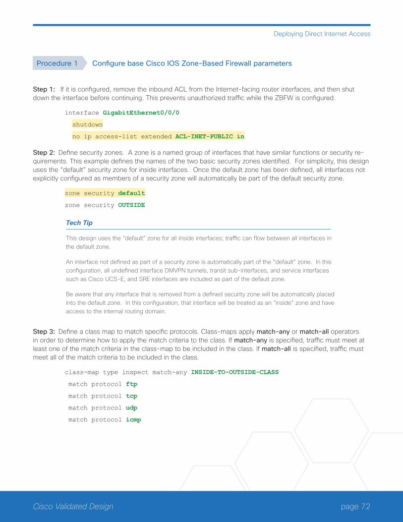
page 72Cisco Validated Design
Deploying Direct Internet Access
Procedure 1 Configure base Cisco IOS Zone-Based Firewall parameters
Step 1: If it is configured, remove the inbound ACL from the Internet-facing router interfaces, and then shut down the interface before continuing. This prevents unauthorized traffic while the ZBFW is configured.
interface GigabitEthernet0/0/0
shutdown
no ip access-list extended ACL-INET-PUBLIC in
Step 2: Define security zones. A zone is a named group of interfaces that have similar functions or security re-quirements. This example defines the names of the two basic security zones identified. For simplicity, this design uses the “default” security zone for inside interfaces. Once the default zone has been defined, all interfaces not explicitly configured as members of a security zone will automatically be part of the default security zone.
zone security default
zone security OUTSIDE
Tech Tip
This design uses the “default” zone for all inside interfaces; traffic can flow between all interfaces in the default zone.
An interface not defined as part of a security zone is automatically part of the “default” zone. In this configuration, all undefined interface DMVPN tunnels, transit sub-interfaces, and service interfaces such as Cisco UCS-E, and SRE interfaces are included as part of the default zone.
Be aware that any interface that is removed from a defined security zone will be automatically placed into the default zone. In this configuration, that interface will be treated as an “inside” zone and have access to the internal routing domain.
Step 3: Define a class map to match specific protocols. Class-maps apply match-any or match-all operators in order to determine how to apply the match criteria to the class. If match-any is specified, traffic must meet at least one of the match criteria in the class-map to be included in the class. If match-all is specified, traffic must meet all of the match criteria to be included in the class.
class-map type inspect match-any INSIDE-TO-OUTSIDE-CLASS
match protocol ftp
match protocol tcp
match protocol udp
match protocol icmp

page 73Cisco Validated Design
Deploying Direct Internet Access
Tech Tip
Protocols that use single ports (such as HTTP, telnet, SSH, etc.) can be statefully allowed with tcp inspection alone by using the match protocol tcp command.
Protocols such as ftp that use multiple ports (one for control and another for data) require application inspection in order to enable dynamic adjustments to the active firewall policy. The specific TCP ports that are required for the application are allowed for short durations, as necessary.
Step 4: Define policy maps. A policy is an association of traffic classes and actions. It specifies what actions should be performed on defined traffic classes. In this case, you statefully inspect the outbound session so that return traffic is permitted.
policy-map type inspect INSIDE-TO-OUTSIDE-POLICY
class type inspect INSIDE-TO-OUTSIDE-CLASS
inspect
class class-default
drop
Tech Tip
An action is a specific functionality that is associated with a traffic class. Inspect, drop, and pass are actions.
With the inspect action, return traffic is automatically allowed for established connections. The pass action permits traffic in one direction only. When using the pass action, you must explicitly define rules for return traffic.
Step 5: Define the zone pair and apply the policy map. A zone pair represents two defined zones and identifies the source and destination zones where a unidirectional firewall policy-map is applied. This configuration uses only one zone pair because all traffic is inspected and thus allowed to return.
zone-pair security IN_OUT source default destination OUTSIDE
service-policy type inspect INSIDE-TO-OUTSIDE-POLICY
Procedure 2 Restrict traffic to the router
Cisco IOS defines the router by using the fixed name self as a separate security zone. The self-zone is the ex-ception to the default deny-all policy.
All traffic destined to or originating from the router itself (local traffic) on any interface is allowed until traffic is explicitly denied. In other words, any traffic flowing directly between defined zones and the router’s IP interfaces is implicitly allowed and is not initially controlled by zone firewall policies.
This default behavior of the self-zone ensures that connectivity to the router’s management interfaces and the function of routing protocols is maintained when an initial zone firewall configuration is applied to the router.

page 74Cisco Validated Design
Deploying Direct Internet Access
Specific rules that control traffic to the self-zone are required. When you configure a ZBFW rule that includes the self-zone, traffic between the self-zone and the other defined zones is immediately restricted in both directions.
Table 2 Self-zone firewall access list parameters
Protocol Stateful inspection policy
ISAKMP Yes
ICMP Yes
DHCP No
ESP No
GRE No
The following configuration allows the required traffic for proper remote-site router configuration with DMVPN. ESP and DHCP cannot be inspected and need to be configured with a pass action in the policy, using separate ACL and class-maps. ISAKMP should be configured with the inspect action and thus needs to be broken out with a separate ACL and class-maps for inbound and outbound policies.
Tech Tip
More specific ACLs than are shown here with the “any” keyword are recommended for added secu-rity.
Step 1: In the following steps, define access lists.
Step 2: Define an ACL allowing traffic with a destination of the router itself from the OUTSIDE zone. This includes ISAKMP for inbound tunnel initiation. This traffic can be inspected and is identified in the following ACL.
ip access-list extended ACL-RTR-IN
permit udp any any eq non500-isakmp
permit udp any any eq isakmp
permit icmp any any echo
permit icmp any any echo-reply
permit icmp any any ttl-exceeded
permit icmp any any port-unreachable
permit udp any any gt 1023 ttl eq 1
Step 3: Identify traffic for IPSEC tunnel initiation and other traffic that will originate from the router (self-zone) to the OUTSIDE zone. This traffic can be inspected.
ip access-list extended ACL-RTR-OUT
permit udp any any eq non500-isakmp
permit udp any any eq isakmp
permit icmp any any
permit udp any any eq domain

page 75Cisco Validated Design
Deploying Direct Internet Access
Tech Tip
The ICMP and domain entries here are for IPSLA probes that originate from the router.
permit icmp any any
permit udp any any eq domain
Step 4: Configure the DHCP ACL to allow the router to acquire a public IP address dynamically from the ISP. This traffic needs to be defined separately for server and client and cannot be inspected.
ip access-list extended DHCP-IN
permit udp any eq bootps any eq bootpc
ip access-list extended DHCP-OUT
permit udp any eq bootpc any eq bootps
Step 5: Configure the ESP ACL to allow the router to establish IPSEC communications for DMVPN. ESP needs to be explicitly allowed inbound and outbound in separate ACLs. ESP cannot be inspected.
ip access-list extended ESP-IN
permit esp any any
ip access-list extended ESP-OUT
permit esp any any
Step 6: Configure the GRE ACL to allow GRE tunnel formation. GRE needs to be explicitly allowed inbound only.
ip access-list extended GRE-IN
permit gre any any
Tech Tip
GRE needs to be permitted inbound for GRE on IOS-XE platforms due to a difference in interface order of operations. This is not required on IOS ISRG2 platforms.
Next, you define class maps for traffic to and from the self-zone. Separate class-maps are required for inbound and outbound initiated flows as well as for traffic that can be inspected by the router.
Step 7: Define the class-map matching inbound traffic that can be inspected.
class-map type inspect match-any INSPECT-ACL-IN-CLASS
match access-group name ACL-RTR-IN
Step 8: Define the class-map matching outbound traffic that can be inspected.
class-map type inspect match-any INSPECT-ACL-OUT-CLASS
match access-group name ACL-RTR-OUT

page 76Cisco Validated Design
Deploying Direct Internet Access
Step 9: Define the class-map matching inbound traffic that is not able to be inspected.
class-map type inspect match-any PASS-ACL-IN-CLASS
match access-group name ESP-IN
match access-group name DHCP-IN
match access-group name GRE-IN
Step 10: Define the class-map matching outbound traffic that cannot be inspected.
class-map type inspect match-any PASS-ACL-OUT-CLASS
match access-group name ESP-OUT
match access-group name DHCP-OUT
Next, you define policy maps. Create two separate policies, one for traffic inbound and one for traffic outbound.
Step 11: Define the inbound policy-map that refers to both of the outbound class-maps with actions of inspect, pass, and drop for the appropriate class defined.
policy-map type inspect ACL-IN-POLICY
class type inspect INSPECT-ACL-IN-CLASS
inspect
class type inspect PASS-ACL-IN-CLASS
pass
class class-default
drop
Step 12: Define the outbound policy-map that refers to both of the outbound class-maps with actions of inspect, pass, and drop for the appropriate class defined.
policy-map type inspect ACL-OUT-POLICY
class type inspect INSPECT-ACL-OUT-CLASS
inspect
class type inspect PASS-ACL-OUT-CLASS
pass
class class-default
drop
Tech Tip
Inspection for Layer 7 applications is not allowed for traffic going to and from the self-zone to other zones. Cisco IOS firewalls support only inspection of TCP, UDP, and H.323 traffic that terminates on or originates from the router itself.
Traffic such as DHCP and ESP cannot be inspected and must be configured as Pass in the associ-ated policy-map.

page 77Cisco Validated Design
Deploying Direct Internet Access
Next, you define the zone pair and apply policy maps to them.
Step 13: Define the zone pair for traffic destined to the self-zone of the router from the outside and associate the inbound policy-map defined in the previous step.
zone-pair security TO-ROUTER source OUTSIDE destination self
service-policy type inspect ACL-IN-POLICY
Step 14: Define the zone pair for traffic destined from the self-zone of the router to the outside and associate the outbound policy-map defined in the previous step.
zone-pair security FROM-ROUTER source self destination OUTSIDE
service-policy type inspect ACL-OUT-POLICY
Procedure 3 Enable and verify zone-based firewall configuration
Step 1: Assign the Internet-facing router interface to the outside security zone. All other interfaces are assigned to the default zone and do not need to be defined.
interface GigabitEthernet0/0/0
description Internet Connection
zone-member security OUTSIDE
Tech Tip
By default, traffic is allowed to flow between interfaces that are members of the same zone, while a default “deny-all” policy is applied to traffic moving between zones.
This design uses the “default” zone for all inside interfaces, traffic can flow between all interfaces in the default zone.
An interface not defined as part of a security zone is automatically part of the “default” zone. In this configuration, all undefined interface DMVPN tunnels, transit sub-interfaces, and service interfaces such as Cisco UCS-E, and SRE interfaces are included as part of the default zone.
Loopback interfaces are members of the “self” zone and are not assigned to a defined security zone or the default zone.

page 78Cisco Validated Design
Deploying Direct Internet Access
Step 2: Verify the interface assignment for the zone firewall and ensure that all required interfaces for the remote site configuration are assigned to the proper zone.
RS32-4451X-2#show zone security
zone self
Description: System defined zone
zone default
Description: System level zone. Interface without zone membership is in this zone automatically
zone OUTSIDE
Member Interfaces:
GigabitEthernet0/0/0
Step 3: Verify firewall operation by reviewing the byte counts for each of the configured policies and classes.
RS32-4451X-2#show policy-map type inspect zone-pair sessions
Zone-pair: FROM-ROUTER
Service-policy inspect : ACL-OUT-POLICY
Class-map: INSPECT-ACL-OUT-CLASS (match-any)
Match: access-group name ACL-RTR-OUT
50 packets, 13824 bytes
Inspect
Class-map: PASS-ACL-OUT-CLASS (match-any)
Match: access-group name ESP-OUT
0 packets, 0 bytes
Match: access-group name DHCP-OUT
8 packets, 2680 bytes
Pass
8 packets, 2680 bytes
Class-map: class-default (match-any)
Match: any
Drop
0 packets, 0 bytes
Zone-pair: IN_OUT
Service-policy inspect : INSIDE-TO-OUTSIDE-POLICY
Class-map: INSIDE-TO-OUTSIDE-CLASS (match-any)
Match: protocol ftp

page 79Cisco Validated Design
Deploying Direct Internet Access
0 packets, 0 bytes
Match: protocol tcp
0 packets, 0 bytes
Match: protocol udp
0 packets, 0 bytes
Match: protocol icmp
0 packets, 0 bytes
Inspect
Class-map: class-default (match-any)
Match: any
Drop
0 packets, 0 bytes
Zone-pair: TO-ROUTER
Service-policy inspect : ACL-IN-POLICY
Class-map: INSPECT-ACL-IN-CLASS (match-any)
Match: access-group name ACL-RTR-IN
52 packets, 14040 bytes
Inspect
Class-map: PASS-ACL-IN-CLASS (match-any)
Match: access-group name ESP-IN
0 packets, 0 bytes
Match: access-group name DHCP-IN
8 packets, 2736 bytes
Match: access-group name GRE-IN
0 packets, 0 bytes
Pass
1697 packets, 332091 bytes
Class-map: class-default (match-any)
Match: any
Drop
0 packets, 0 bytes
Step 4: Add the following command to the router configuration in order to identify traffic dropped by the Cisco IOS-XE zone firewall.
parameter-map type inspect global
log dropped-packets

page 80Cisco Validated Design
Deploying Direct Internet Access
Tech Tip
In IOS, when you configure the command ip inspect drop-pkt, the following is automatically added to the router configuration:
parameter-map type inspect global
log dropped-packets enable
Configuring Additional Router Security
1. Disable IP ICMP redirects
2. Disable ICMP unreachable messages
3. Disable Proxy ARP
4. Disable unused router services
5. Disable CDP and LLDP
6. Enable keepalives for TCP sessions
7. Configure internal-network floating static routes
8. Enable Internet interface
PR
OC
ESS
In addition to the security measures already taken in prior configuration tasks, this section introduces best prac-tices recommendations to secure Internet-facing routers. Disabling unused services and features for networking devices improves the overall security posture by minimizing the amount of information exposed. This practice also minimizes the amount of router CPU and memory load that is required to process unneeded packets.
Figure 55 Additional router security
13
05
F
SecureRemote Site
DMVPN
Exploits
Internet
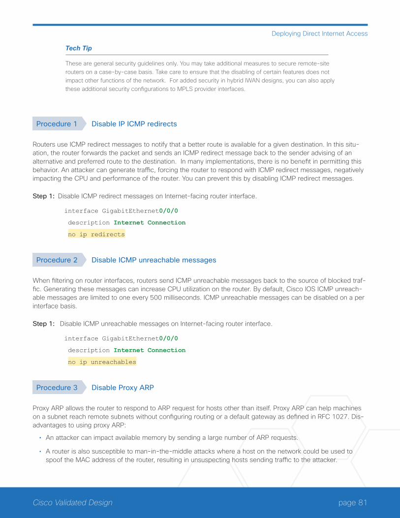
page 81Cisco Validated Design
Deploying Direct Internet Access
Tech Tip
These are general security guidelines only. You may take additional measures to secure remote-site routers on a case-by-case basis. Take care to ensure that the disabling of certain features does not impact other functions of the network. For added security in hybrid IWAN designs, you can also apply these additional security configurations to MPLS provider interfaces.
Procedure 1 Disable IP ICMP redirects
Routers use ICMP redirect messages to notify that a better route is available for a given destination. In this situ-ation, the router forwards the packet and sends an ICMP redirect message back to the sender advising of an alternative and preferred route to the destination. In many implementations, there is no benefit in permitting this behavior. An attacker can generate traffic, forcing the router to respond with ICMP redirect messages, negatively impacting the CPU and performance of the router. You can prevent this by disabling ICMP redirect messages.
Step 1: Disable ICMP redirect messages on Internet-facing router interface.
interface GigabitEthernet0/0/0
description Internet Connection
no ip redirects
Procedure 2 Disable ICMP unreachable messages
When filtering on router interfaces, routers send ICMP unreachable messages back to the source of blocked traf-fic. Generating these messages can increase CPU utilization on the router. By default, Cisco IOS ICMP unreach-able messages are limited to one every 500 milliseconds. ICMP unreachable messages can be disabled on a per interface basis.
Step 1: Disable ICMP unreachable messages on Internet-facing router interface.
interface GigabitEthernet0/0/0
description Internet Connection
no ip unreachables
Procedure 3 Disable Proxy ARP
Proxy ARP allows the router to respond to ARP request for hosts other than itself. Proxy ARP can help machines on a subnet reach remote subnets without configuring routing or a default gateway as defined in RFC 1027. Dis-advantages to using proxy ARP:
• An attacker can impact available memory by sending a large number of ARP requests.
• A router is also susceptible to man-in-the-middle attacks where a host on the network could be used to spoof the MAC address of the router, resulting in unsuspecting hosts sending traffic to the attacker.

page 82Cisco Validated Design
Deploying Direct Internet Access
You can disable proxy ARP by using the interface configuration command.
Step 1: Disable proxy ARP on Internet-facing router interface.
interface GigabitEthernet0/0/0
description Internet Connection
no ip proxy-arp
Procedure 4 Disable unused router services
As a security best practice, you should disable all unnecessary services that could be used to launch DoS and other attacks. Many unused services that pose a security threat are disabled by default in current Cisco IOS versions.
Step 1: Disable MOP on Internet-facing router interface.
interface GigabitEthernet0/0/0
description Internet Connection
no mop enabled
Step 2: Disable PAD service globally on the router.
no service pad
Step 3: Prevent the router from attempting to locate a configuration file via TFTP globally on the router.
no service config
Procedure 5 Disable CDP and LLDP
Attackers can use CDP and LLDP for reconnaissance and network mapping. CDP is a network protocol that is used to discover other CDP-enabled devices. CDP is often used by NMS and for troubleshooting networking problems. LLDP is an IEEE protocol that is defined in 802.1AB and is very similar to CDP. You should disable CDP and LLDP on router interfaces that connect to untrusted networks.
Step 1: Disable CDP on Internet-facing router interface.
interface GigabitEthernet0/0/0
description Internet Connection
no cdp enable
Step 2: Disable LLDP on Internet-facing router interface.
interface GigabitEthernet0/0/0
description Internet Connection
no lldp transmit
no lldp receive
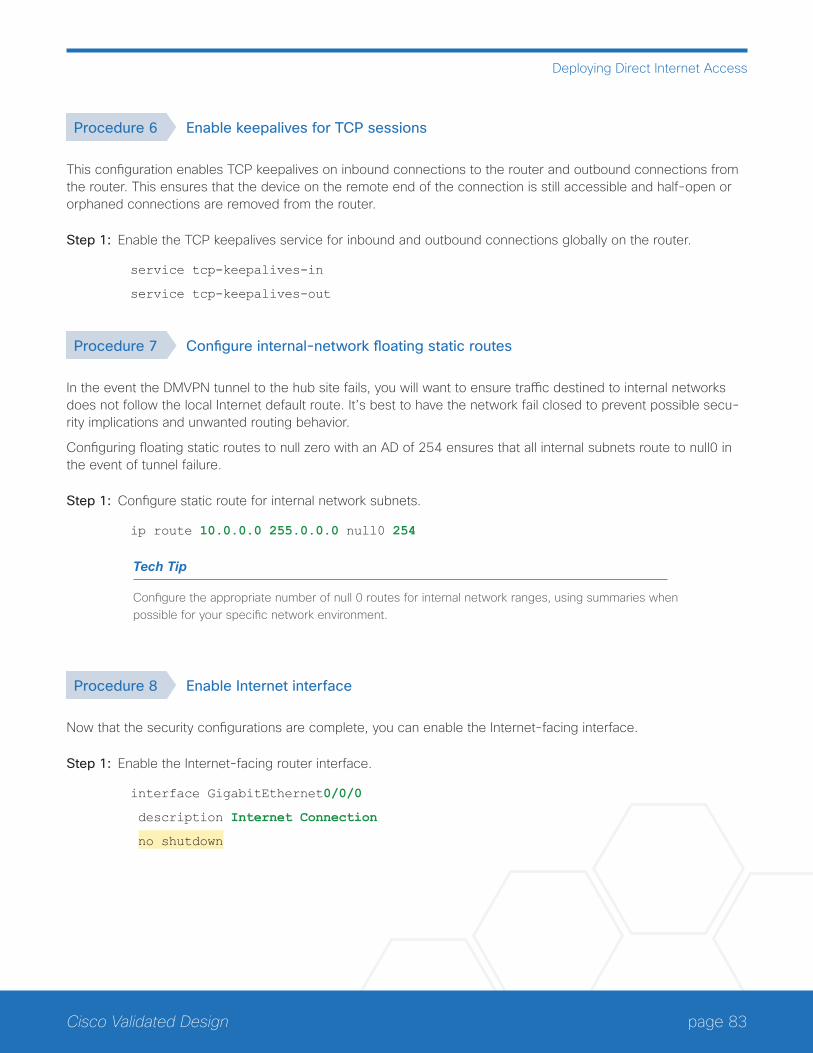
page 83Cisco Validated Design
Deploying Direct Internet Access
Procedure 6 Enable keepalives for TCP sessions
This configuration enables TCP keepalives on inbound connections to the router and outbound connections from the router. This ensures that the device on the remote end of the connection is still accessible and half-open or orphaned connections are removed from the router.
Step 1: Enable the TCP keepalives service for inbound and outbound connections globally on the router.
service tcp-keepalives-in
service tcp-keepalives-out
Procedure 7 Configure internal-network floating static routes
In the event the DMVPN tunnel to the hub site fails, you will want to ensure traffic destined to internal networks does not follow the local Internet default route. It’s best to have the network fail closed to prevent possible secu-rity implications and unwanted routing behavior.
Configuring floating static routes to null zero with an AD of 254 ensures that all internal subnets route to null0 in the event of tunnel failure.
Step 1: Configure static route for internal network subnets.
ip route 10.0.0.0 255.0.0.0 null0 254
Tech Tip
Configure the appropriate number of null 0 routes for internal network ranges, using summaries when possible for your specific network environment.
Procedure 8 Enable Internet interface
Now that the security configurations are complete, you can enable the Internet-facing interface.
Step 1: Enable the Internet-facing router interface.
interface GigabitEthernet0/0/0
description Internet Connection
no shutdown
page 84Cisco Validated Design
Deploying Direct Internet Access
Configuring ISP Black-Hole Routing Detection
1. Configure ISP black-hole routing detection
PR
OC
ESS
In many cases you will need to ensure connectivity issues with your ISP does not cause black-hole routing condi-tions. Failure conditions can exist where the DHCP address and routes are not removed from the remote-site router when connectivity issues exist with the broadband service or local premise equipment. There may also be circumstances if certain services are unreachable within via the local ISP connection that you want to reroute to a secondary Internet service.
Tech Tip
This configuration requires you to turn off PfR load-balancing on the Hub Master Controller. If PfR load-balancing is not turned off, the traffic will fail over to the central site Internet path, but it will not return to the local DIA interface after the failure condition is resolved.
If PfR load-balancing is a requirement for your environment, see “Appendix C: DIA with PfR Load-Balancing” for an alternate way to configure your hybrid remote sites.
If central Internet fallback is required and you do not need PfR load-balancing, configure one or more of the fol-lowing options on the secondary router.
Procedure 1 Configure ISP black-hole routing detection
Option 1: DMVPN Tunnel State Tracking
In this solution, the DMVPN tunnel state is used to monitor the status of the ISP connection used as the primary path for local Internet traffic. In this example, a “down” state of the tunnel interface triggers the removal of the default route via an EEM script. If tunnel state is “up,” the route will remain.
Tech Tip
With this method a failure or maintenance at the central site can cause a failover event where the route is removed due to tunnel state change and the local Internet connection remains active at the remote site. In hybrid configurations this can cause failover to Central Internet for multiple sites. It is recommended that you use the other options presented in this guide for hybrid DIA configurations.

page 85Cisco Validated Design
Deploying Direct Internet Access
Figure 56 IWAN tunnel tracking with EEM
12
97
F
VPN T
unne
l
TunnelState
Step 1: Ensure that state tracking is configured for the DMVPN tunnel interface on the secondary router.
interface Tunnel11
if-state nhrp
Step 2: Configure the tracking parameters and logic for the IPSLA probes on the secondary router.
track 80 interface Tunnel10 line-protocol
Step 3: On the secondary router, configure an EEM script to remove the local default route when the tunnel line protocol transitions to a “down” state.
event manager applet DISABLE-IWAN-DIA-DEFAULT
description ISP Black hole Detection - Tunnel state
event track 80 state down
action 1 cli command "enable"
action 2 cli command "configure terminal"
action 3 cli command "no ip route 0.0.0.0 0.0.0.0 GigabitEthernet0/0/0 dhcp 10"
action 4 cli command "end"
action 99 syslog msg "IWAN DIA DEFAULT IP ROUTE via GIG0/0/0 DISABLED"
Step 4: On the secondary router, configure an EEM script to also restore the local default route when the tunnel state tracking object is “up”.
event manager applet ENABLE-IWAN-DIA-DEFAULT
description ISP Black hole Detection - Tunnel state
event track 80 state up
action 1 cli command "enable"
action 2 cli command "configure terminal"
action 3 cli command "ip route 0.0.0.0 0.0.0.0 GigabitEthernet0/0/0 dhcp 10"
action 4 cli command "end"
action 99 syslog msg "IWAN DIA DEFAULT IP ROUTE via GIG0/0/0 ENABLED"

page 86Cisco Validated Design
Deploying Direct Internet Access
Option 2: DNS-Based IPSLA Probes
In this solution, you use DNS-based IPSLA probes to monitor the status of the ISP connection used as the pri-mary path for local Internet traffic. In this example, the failure of DNS probes to two or more root DNS servers triggers the removal of the default route via an EEM script. If any DNS probe is active, the route will remain.
Figure 57 IPSLA with DNS probes
12
99
F
VPN T
unne
l
IP SLA DNSProbes
Tech Tip
For DNS-based IPSLA probes to function, you need to ensure that DNS or “domain” is permitted in the ZBFW outbound ACL, from the self-zone to the OUTSIDE zone. Example:
ip access-list extended ACL-RTR-OUT
permit udp any any eq domain
Step 1: On the secondary router, configure the VRF-aware IPSLA DNS probes.
ip sla 118
dns d.root-servers.net name-server 199.7.91.13
vrf IWAN-TRANSPORT-2
threshold 1000
timeout 3000
frequency 15
ip sla schedule 118 life forever start-time now
ip sla 119
dns b.root-servers.net name-server 192.228.79.201
vrf IWAN-TRANSPORT-2
threshold 1000
timeout 3000
frequency 15
ip sla schedule 119 life forever start-time now
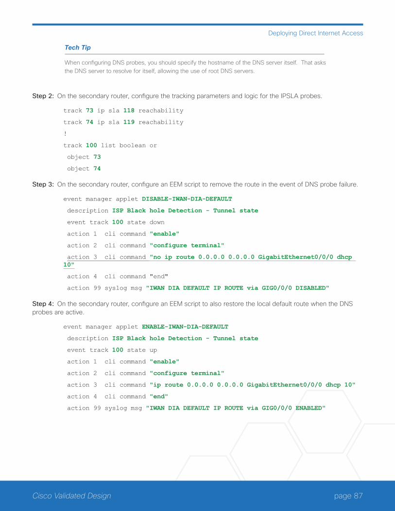
page 87Cisco Validated Design
Deploying Direct Internet Access
Tech Tip
When configuring DNS probes, you should specify the hostname of the DNS server itself. That asks the DNS server to resolve for itself, allowing the use of root DNS servers.
Step 2: On the secondary router, configure the tracking parameters and logic for the IPSLA probes.
track 73 ip sla 118 reachability
track 74 ip sla 119 reachability
!
track 100 list boolean or
object 73
object 74
Step 3: On the secondary router, configure an EEM script to remove the route in the event of DNS probe failure.
event manager applet DISABLE-IWAN-DIA-DEFAULT
description ISP Black hole Detection - Tunnel state
event track 100 state down
action 1 cli command "enable"
action 2 cli command "configure terminal"
action 3 cli command "no ip route 0.0.0.0 0.0.0.0 GigabitEthernet0/0/0 dhcp 10"
action 4 cli command "end"
action 99 syslog msg "IWAN DIA DEFAULT IP ROUTE via GIG0/0/0 DISABLED"
Step 4: On the secondary router, configure an EEM script to also restore the local default route when the DNS probes are active.
event manager applet ENABLE-IWAN-DIA-DEFAULT
description ISP Black hole Detection - Tunnel state
event track 100 state up
action 1 cli command "enable"
action 2 cli command "configure terminal"
action 3 cli command "ip route 0.0.0.0 0.0.0.0 GigabitEthernet0/0/0 dhcp 10"
action 4 cli command "end"
action 99 syslog msg "IWAN DIA DEFAULT IP ROUTE via GIG0/0/0 ENABLED"
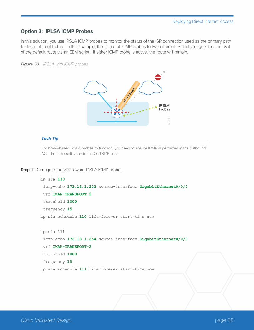
page 88Cisco Validated Design
Deploying Direct Internet Access
Option 3: IPLSA ICMP Probes
In this solution, you use IPSLA ICMP probes to monitor the status of the ISP connection used as the primary path for local Internet traffic. In this example, the failure of ICMP probes to two different IP hosts triggers the removal of the default route via an EEM script. If either ICMP probe is active, the route will remain.
Figure 58 IPSLA with ICMP probes
12
98
F
VPN T
unne
l
IP SLAProbes
Tech Tip
For ICMP-based IPSLA probes to function, you need to ensure ICMP is permitted in the outbound ACL, from the self-zone to the OUTSIDE zone.
Step 1: Configure the VRF-aware IPSLA ICMP probes.
ip sla 110
icmp-echo 172.18.1.253 source-interface GigabitEthernet0/0/0
vrf IWAN-TRANSPORT-2
threshold 1000
frequency 15
ip sla schedule 110 life forever start-time now
ip sla 111
icmp-echo 172.18.1.254 source-interface GigabitEthernet0/0/0
vrf IWAN-TRANSPORT-2
threshold 1000
frequency 15
ip sla schedule 111 life forever start-time now

page 89Cisco Validated Design
Deploying Direct Internet Access
Step 2: Configure the tracking parameters and logic for the IPSLA ICMP probes.
track 60 ip sla 110 reachability
track 61 ip sla 111 reachability
track 62 list boolean or
object 60
object 61
Step 3: Configure the EEM script to remove the route when the ICMP probes are down.
event manager applet DISABLE-IWAN-DIA-DEFAULT
description ISP Black hole Detection - Tunnel state
event track 62 state down
action 1 cli command "enable"
action 2 cli command "configure terminal"
action 3 cli command "no ip route 0.0.0.0 0.0.0.0 GigabitEthernet0/0/0 dhcp 10"
action 4 cli command "end"
action 99 syslog msg "IWAN DIA DEFAULT IP ROUTE via GIG0/0/0 DISABLED"
Step 4: Configure the EEM script to also restore the local default route when the ICMP probes are active.
event manager applet ENABLE-IWAN-DIA-DEFAULT
description ISP Black hole Detection - Tunnel state
event track 62 state up
action 1 cli command "enable"
action 2 cli command "configure terminal"
action 3 cli command "ip route 0.0.0.0 0.0.0.0 GigabitEthernet0/0/0 dhcp 10"
action 4 cli command "end"
action 99 syslog msg "IWAN DIA DEFAULT IP ROUTE via GIG0/0/0 ENABLED"
IWAN SINGLE-ROUTER DUAL-INTERNET REMOTE SITE WITH DIAThis section describes configuring DIA for the single-router dual-Internet IWAN design. . These configurations assume that the single-router dual-Internet site with centralized Internet access is configured and functional, as described in the Intelligent WAN Deployment Guide.
In this section, you convert a remote site from centralized Internet access for employees to a secure DIA configu-ration.

page 90Cisco Validated Design
Deploying Direct Internet Access
Figure 59 IWAN single-router dual-Internet with DIA
13
25
F
Internet Internet
Ciscowebex
Configuring DIA Routing
1. Configure Internet interfaces
2. Filter learned central default route
3. Configure local default routing for outbound local Internet traffic
4. Configure local policy routing for return Internet traffic
PR
OC
ESS
In the following procedures, you enable DIA routing, NAT and zone-based firewall configurations for the single-router dual-Internet IWAN design. In this configuration, local internet traffic will be routed using split-tunneling outside the DMVPN tunnel. All configurations are specific to this design model.
Procedure 1 Configure Internet interfaces
For security, disable the ISP interface before configuring DIA. You will not restore this interface until you complete all of the configurations in this section.
Tech Tip
If you are remotely connected to the remote-site router via SSH, you will be disconnected from the router console. Shutting down the Internet interfaces will drop the existing DMVPN tunnel.
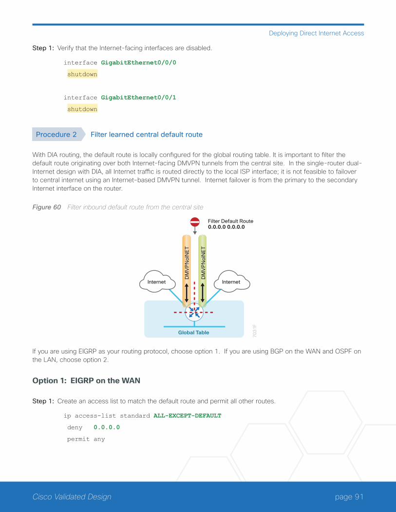
page 91Cisco Validated Design
Deploying Direct Internet Access
Step 1: Verify that the Internet-facing interfaces are disabled.
interface GigabitEthernet0/0/0
shutdown
interface GigabitEthernet0/0/1
shutdown
Procedure 2 Filter learned central default route
With DIA routing, the default route is locally configured for the global routing table. It is important to filter the default route originating over both Internet-facing DMVPN tunnels from the central site. In the single-router dual-Internet design with DIA, all Internet traffic is routed directly to the local ISP interface; it is not feasible to failover to central internet using an Internet-based DMVPN tunnel. Internet failover is from the primary to the secondary Internet interface on the router.
Figure 60 Filter inbound default route from the central site
Global Table
70
31
F
DM
VP
No
INE
T
DM
VP
No
INE
T
InternetInternet
Filter Default Route0.0.0.0 0.0.0.0
If you are using EIGRP as your routing protocol, choose option 1. If you are using BGP on the WAN and OSPF on the LAN, choose option 2.
Option 1: EIGRP on the WAN
Step 1: Create an access list to match the default route and permit all other routes.
ip access-list standard ALL-EXCEPT-DEFAULT
deny 0.0.0.0
permit any

page 92Cisco Validated Design
Deploying Direct Internet Access
Step 2: Create a route-map to reference the access list.
route-map BLOCK-DEFAULT permit 10
description block only the default route inbound from the WAN
match ip address ALL-EXCEPT-DEFAULT
Step 3: Apply the policy as an inbound distribute list for the Internet-facing DMVPN tunnel interface.
router eigrp IWAN-EIGRP
address-family ipv4 unicast autonomous-system 400
topology base
distribute-list route-map BLOCK-DEFAULT in tunnel20
distribute-list route-map BLOCK-DEFAULT in tunnel21
exit-af-topology
exit-address-family
Option 2: BGP on the WAN
Step 1: Create an ip prefix-list to match the default route.
ip prefix-list ALL-EXCEPT-DEFAULT seq 10 permit 0.0.0.0/0
Step 2: Create a route-map to reference the ip prefix list.
route-map BLOCK-DEFAULT deny 10
description Block only the default route inbound from the WAN
match ip address prefix-list ALL-EXCEPT-DEFAULT
route-map BLOCK-DEFAULT permit 100
description Permit all other routes
Step 3: Apply the policy as an inbound route-map for the Internet-facing DMVPN tunnel interface.
router bgp 65100
address-family ipv4
neighbor INET1-HUB route-map BLOCK-DEFAULT in
neighbor INET2-HUB route-map BLOCK-DEFAULT in
exit-address-family
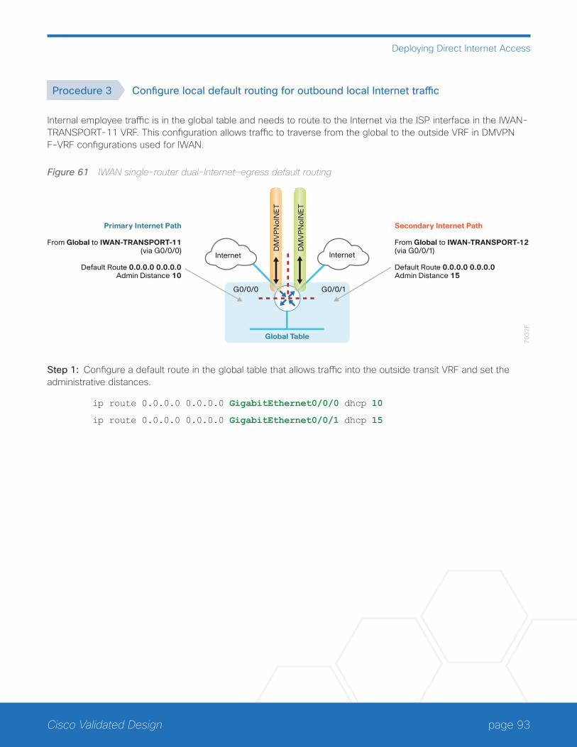
page 93Cisco Validated Design
Deploying Direct Internet Access
Procedure 3 Configure local default routing for outbound local Internet traffic
Internal employee traffic is in the global table and needs to route to the Internet via the ISP interface in the IWAN-TRANSPORT-11 VRF. This configuration allows traffic to traverse from the global to the outside VRF in DMVPN F-VRF configurations used for IWAN.
Figure 61 IWAN single-router dual-Internet—egress default routing
70
32
F
DM
VP
No
INE
T
DM
VP
No
INE
T
Global Table
InternetInternet
Primary Internet Path
From Global to IWAN-TRANSPORT-11(via G0/0/0)
Default Route 0.0.0.0 0.0.0.0Admin Distance 10
Secondary Internet Path
From Global to IWAN-TRANSPORT-12(via G0/0/1)
Default Route 0.0.0.0 0.0.0.0Admin Distance 15
G0/0/1G0/0/0
Step 1: Configure a default route in the global table that allows traffic into the outside transit VRF and set the administrative distances.
ip route 0.0.0.0 0.0.0.0 GigabitEthernet0/0/0 dhcp 10
ip route 0.0.0.0 0.0.0.0 GigabitEthernet0/0/1 dhcp 15

page 94Cisco Validated Design
Deploying Direct Internet Access
Procedure 4 Configure local policy routing for return Internet traffic
Traffic returning to the outside NAT address of the router ISP interface will be contained inside the IWAN-TRANS-PORT-11 and IWAN-TRANSPORT-12 VRFs. The local policy configuration allows this traffic to be routed back to the global table.
Figure 62 IWAN single-router dual-Internet—local policy return routing
70
33
F
DM
VP
No
INE
T
DM
VP
No
INE
T
InternetInternetFrom IWAN-TRANSPORT-11 to Global
Policy Route for 10.0.0.0/8 trafficSet next-hop VRF to Global Table
From IWAN-TRANSPORT-12 to Global
Policy Route for 10.0.0.0/8 trafficSet next-hop VRF to Global Table
G0/0/1G0/0/0
Step 1: Configure an ACL that matches the summary range of the internal IP networks.
ip access-list extended INTERNAL-NETS
permit ip any 10.0.0.0 0.255.255.255
Step 2: Create a route map that references the ACL and changes the traffic to the global table.
route-map INET-INTERNAL permit 10
description Return routing for Local Internet Access
match ip address INTERNAL-NETS
set global
Step 3: Apply the local policy routing configuration to the Internet-facing router interfaces.
interface GigabitEthernet0/0/0
ip policy route-map INET-INTERNAL
interface GigabitEthernet0/0/1
ip policy route-map INET-INTERNAL
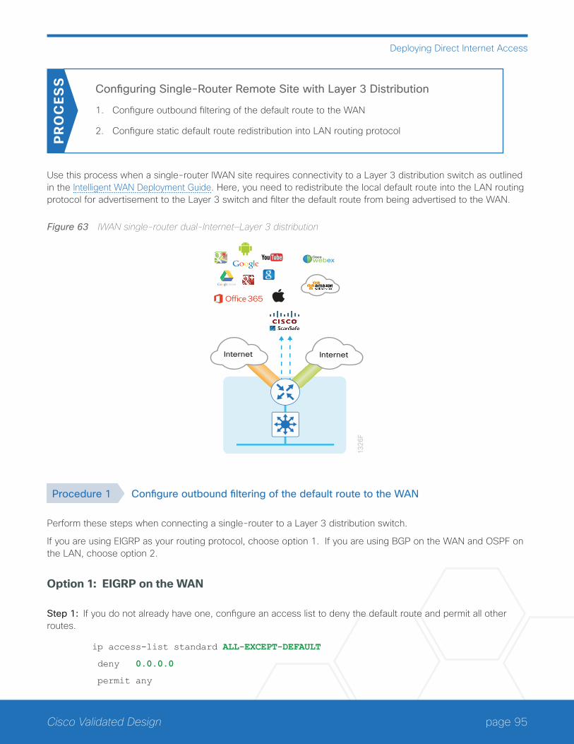
page 95Cisco Validated Design
Deploying Direct Internet Access
Configuring Single-Router Remote Site with Layer 3 Distribution
1. Configure outbound filtering of the default route to the WAN
2. Configure static default route redistribution into LAN routing protocol
PR
OC
ESS
Use this process when a single-router IWAN site requires connectivity to a Layer 3 distribution switch as outlined in the Intelligent WAN Deployment Guide. Here, you need to redistribute the local default route into the LAN routing protocol for advertisement to the Layer 3 switch and filter the default route from being advertised to the WAN.
Figure 63 IWAN single-router dual-Internet—Layer 3 distribution
1326
FInternet Internet
Ciscowebex
Procedure 1 Configure outbound filtering of the default route to the WAN
Perform these steps when connecting a single-router to a Layer 3 distribution switch.
If you are using EIGRP as your routing protocol, choose option 1. If you are using BGP on the WAN and OSPF on the LAN, choose option 2.
Option 1: EIGRP on the WAN
Step 1: If you do not already have one, configure an access list to deny the default route and permit all other routes.
ip access-list standard ALL-EXCEPT-DEFAULT
deny 0.0.0.0
permit any
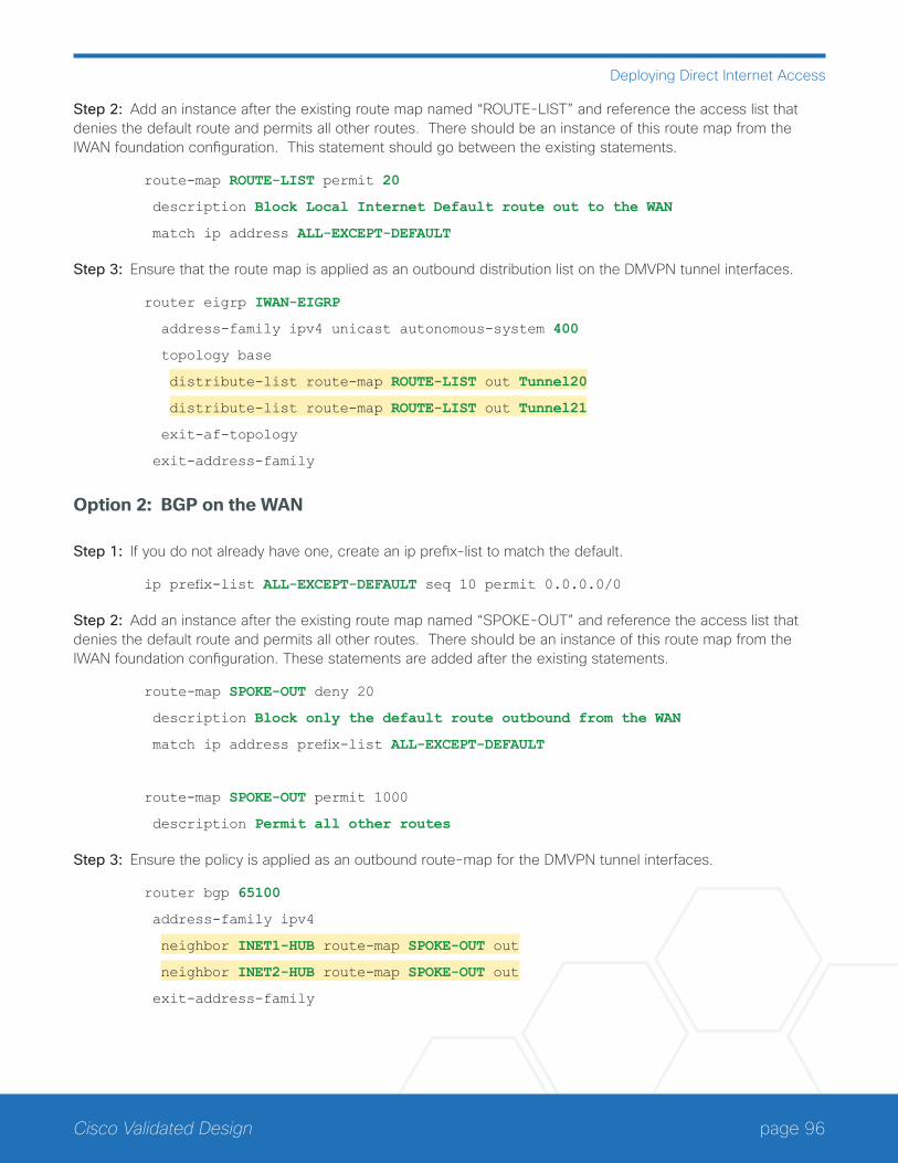
page 96Cisco Validated Design
Deploying Direct Internet Access
Step 2: Add an instance after the existing route map named “ROUTE-LIST” and reference the access list that denies the default route and permits all other routes. There should be an instance of this route map from the IWAN foundation configuration. This statement should go between the existing statements.
route-map ROUTE-LIST permit 20
description Block Local Internet Default route out to the WAN
match ip address ALL-EXCEPT-DEFAULT
Step 3: Ensure that the route map is applied as an outbound distribution list on the DMVPN tunnel interfaces.
router eigrp IWAN-EIGRP
address-family ipv4 unicast autonomous-system 400
topology base
distribute-list route-map ROUTE-LIST out Tunnel20
distribute-list route-map ROUTE-LIST out Tunnel21
exit-af-topology
exit-address-family
Option 2: BGP on the WAN
Step 1: If you do not already have one, create an ip prefix-list to match the default.
ip prefix-list ALL-EXCEPT-DEFAULT seq 10 permit 0.0.0.0/0
Step 2: Add an instance after the existing route map named “SPOKE-OUT” and reference the access list that denies the default route and permits all other routes. There should be an instance of this route map from the IWAN foundation configuration. These statements are added after the existing statements.
route-map SPOKE-OUT deny 20
description Block only the default route outbound from the WAN
match ip address prefix-list ALL-EXCEPT-DEFAULT
route-map SPOKE-OUT permit 1000
description Permit all other routes
Step 3: Ensure the policy is applied as an outbound route-map for the DMVPN tunnel interfaces.
router bgp 65100
address-family ipv4
neighbor INET1-HUB route-map SPOKE-OUT out
neighbor INET2-HUB route-map SPOKE-OUT out
exit-address-family
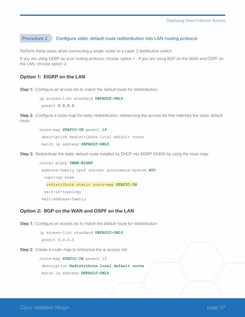
page 97Cisco Validated Design
Deploying Direct Internet Access
Procedure 2 Configure static default route redistribution into LAN routing protocol
Perform these steps when connecting a single router to a Layer 3 distribution switch.
If you are using EIGRP as your routing protocol, choose option 1. If you are using BGP on the WAN and OSPF on the LAN, choose option 2.
Option 1: EIGRP on the LAN
Step 1: Configure an access list to match the default route for redistribution.
ip access-list standard DEFAULT-ONLY
permit 0.0.0.0
Step 2: Configure a route map for static redistribution, referencing the access list that matches the static default route.
route-map STATIC-IN permit 10
description Redistribute local default route
match ip address DEFAULT-ONLY
Step 3: Redistribute the static default route installed by DHCP into EIGRP AS400 by using the route map.
router eigrp IWAN-EIGRP
address-family ipv4 unicast autonomous-system 400
topology base
redistribute static route-map STATIC-IN
exit-af-topology
exit-address-family
Option 2: BGP on the WAN and OSPF on the LAN
Step 1: Configure an access list to match the default route for redistribution.
ip access-list standard DEFAULT-ONLY
permit 0.0.0.0
Step 2: Create a route-map to reference the ip access-list.
route-map STATIC-IN permit 10
description Redistribute local default route
match ip address DEFAULT-ONLY
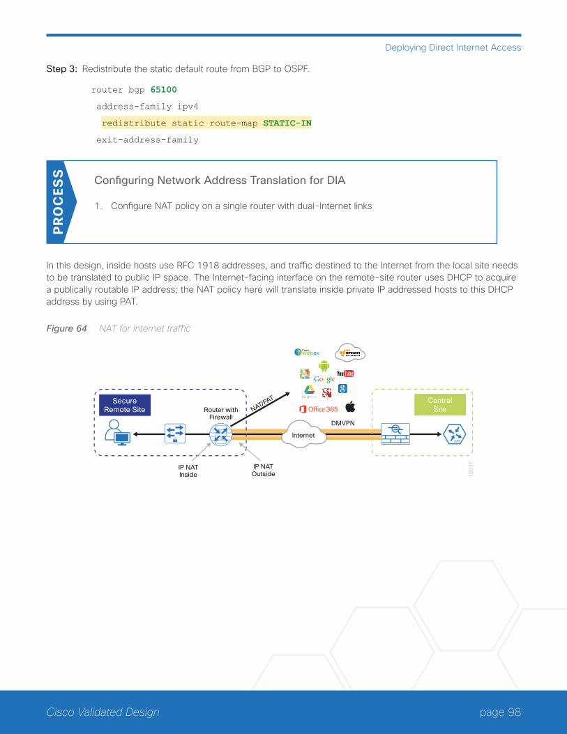
page 98Cisco Validated Design
Deploying Direct Internet Access
Step 3: Redistribute the static default route from BGP to OSPF.
router bgp 65100
address-family ipv4
redistribute static route-map STATIC-IN
exit-address-family
Configuring Network Address Translation for DIA
1. Configure NAT policy on a single router with dual-Internet links
PR
OC
ESS
In this design, inside hosts use RFC 1918 addresses, and traffic destined to the Internet from the local site needs to be translated to public IP space. The Internet-facing interface on the remote-site router uses DHCP to acquire a publically routable IP address; the NAT policy here will translate inside private IP addressed hosts to this DHCP address by using PAT.
Figure 64 NAT for Internet traffic
13
01
F
DMVPN
IP NATInside
Router withFirewall
IP NATOutside
CentralSite
SecureRemote Site NAT/PAT
Ciscowebex
Internet
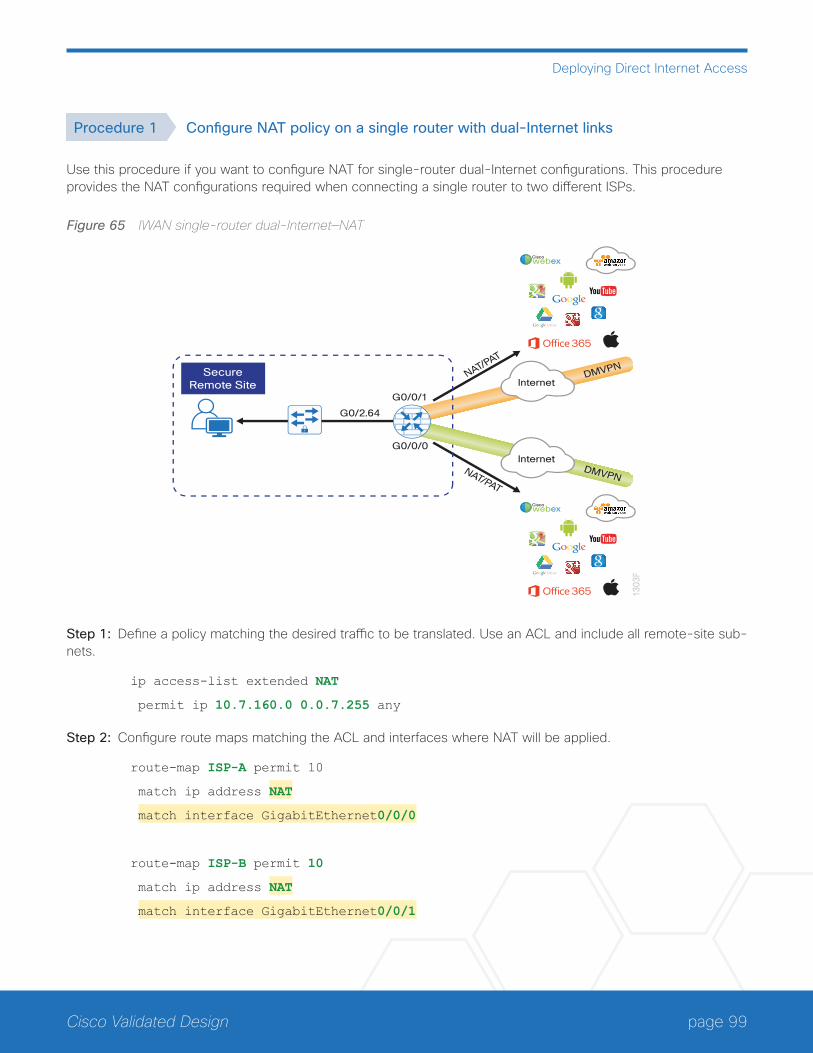
page 99Cisco Validated Design
Deploying Direct Internet Access
Procedure 1 Configure NAT policy on a single router with dual-Internet links
Use this procedure if you want to configure NAT for single-router dual-Internet configurations. This procedure provides the NAT configurations required when connecting a single router to two different ISPs.
Figure 65 IWAN single-router dual-Internet—NAT
1303
F
DMVPN
G0/0/1
SecureRemote Site
G0/2.64
NAT/PAT
G0/0/0
DMVPNNAT/PAT
Internet
Internet
Ciscowebex
Ciscowebex
Step 1: Define a policy matching the desired traffic to be translated. Use an ACL and include all remote-site sub-nets.
ip access-list extended NAT
permit ip 10.7.160.0 0.0.7.255 any
Step 2: Configure route maps matching the ACL and interfaces where NAT will be applied.
route-map ISP-A permit 10
match ip address NAT
match interface GigabitEthernet0/0/0
route-map ISP-B permit 10
match ip address NAT
match interface GigabitEthernet0/0/1
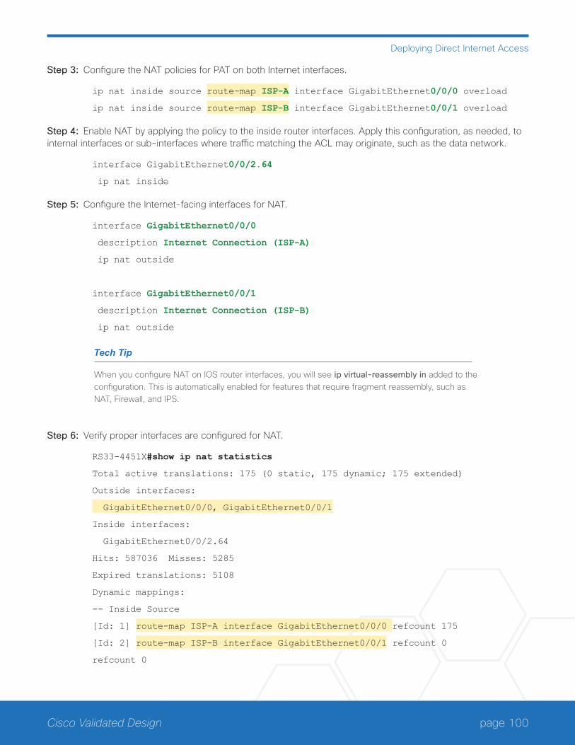
page 100Cisco Validated Design
Deploying Direct Internet Access
Step 3: Configure the NAT policies for PAT on both Internet interfaces.
ip nat inside source route-map ISP-A interface GigabitEthernet0/0/0 overload
ip nat inside source route-map ISP-B interface GigabitEthernet0/0/1 overload
Step 4: Enable NAT by applying the policy to the inside router interfaces. Apply this configuration, as needed, to internal interfaces or sub-interfaces where traffic matching the ACL may originate, such as the data network.
interface GigabitEthernet0/0/2.64
ip nat inside
Step 5: Configure the Internet-facing interfaces for NAT.
interface GigabitEthernet0/0/0
description Internet Connection (ISP-A)
ip nat outside
interface GigabitEthernet0/0/1
description Internet Connection (ISP-B)
ip nat outside
Tech Tip
When you configure NAT on IOS router interfaces, you will see ip virtual-reassembly in added to the configuration. This is automatically enabled for features that require fragment reassembly, such as NAT, Firewall, and IPS.
Step 6: Verify proper interfaces are configured for NAT.
RS33-4451X#show ip nat statistics
Total active translations: 175 (0 static, 175 dynamic; 175 extended)
Outside interfaces:
GigabitEthernet0/0/0, GigabitEthernet0/0/1
Inside interfaces:
GigabitEthernet0/0/2.64
Hits: 587036 Misses: 5285
Expired translations: 5108
Dynamic mappings:
-- Inside Source
[Id: 1] route-map ISP-A interface GigabitEthernet0/0/0 refcount 175
[Id: 2] route-map ISP-B interface GigabitEthernet0/0/1 refcount 0
refcount 0
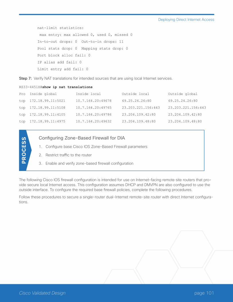
page 101Cisco Validated Design
Deploying Direct Internet Access
nat-limit statistics:
max entry: max allowed 0, used 0, missed 0
In-to-out drops: 0 Out-to-in drops: 11
Pool stats drop: 0 Mapping stats drop: 0
Port block alloc fail: 0
IP alias add fail: 0
Limit entry add fail: 0
Step 7: Verify NAT translations for intended sources that are using local Internet services.
RS33-4451X#show ip nat translations
Pro Inside global Inside local Outside local Outside global
tcp 172.18.99.11:5021 10.7.164.20:49678 69.25.24.26:80 69.25.24.26:80
tcp 172.18.99.11:5108 10.7.164.20:49765 23.203.221.156:443 23.203.221.156:443
tcp 172.18.99.11:4105 10.7.164.20:49786 23.204.109.42:80 23.204.109.42:80
tcp 172.18.99.11:4975 10.7.164.20:49632 23.204.109.48:80 23.204.109.48:80
Configuring Zone-Based Firewall for DIA
1. Configure base Cisco IOS Zone-Based Firewall parameters
2. Restrict traffic to the router
3. Enable and verify zone-based firewall configurationPR
OC
ESS
The following Cisco IOS firewall configuration is intended for use on Internet-facing remote site routers that pro-vide secure local Internet access. This configuration assumes DHCP and DMVPN are also configured to use the outside interface. To configure the required base firewall policies, complete the following procedures.
Follow these procedures to secure a single-router dual-Internet remote-site router with direct Internet configura-tions.
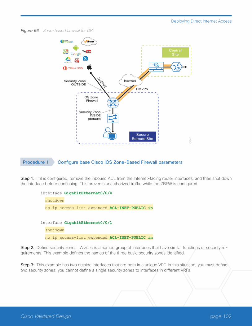
page 102Cisco Validated Design
Deploying Direct Internet Access
Figure 66 Zone-based firewall for DIA
1304
F
CentralSite
SecureRemote Site
IOS ZoneFirewall
DMVPN
Security ZoneOUTSIDE
Security ZoneINSIDE
(default)
NAT/PAT
Internet
Ciscowebex
Procedure 1 Configure base Cisco IOS Zone-Based Firewall parameters
Step 1: If it is configured, remove the inbound ACL from the Internet-facing router interfaces, and then shut down the interface before continuing. This prevents unauthorized traffic while the ZBFW is configured.
interface GigabitEthernet0/0/0
shutdown
no ip access-list extended ACL-INET-PUBLIC in
interface GigabitEthernet0/0/1
shutdown
no ip access-list extended ACL-INET-PUBLIC in
Step 2: Define security zones. A zone is a named group of interfaces that have similar functions or security re-quirements. This example defines the names of the three basic security zones identified.
Step 3: This example has two outside interfaces that are both in a unique VRF. In this situation, you must define two security zones; you cannot define a single security zones to interfaces in different VRFs.
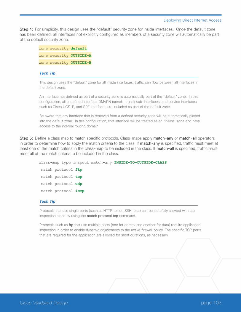
page 103Cisco Validated Design
Deploying Direct Internet Access
Step 4: For simplicity, this design uses the “default” security zone for inside interfaces. Once the default zone has been defined, all interfaces not explicitly configured as members of a security zone will automatically be part of the default security zone.
zone security default
zone security OUTSIDE-A
zone security OUTSIDE-B
Tech Tip
This design uses the “default” zone for all inside interfaces; traffic can flow between all interfaces in the default zone.
An interface not defined as part of a security zone is automatically part of the “default” zone. In this configuration, all undefined interface DMVPN tunnels, transit sub-interfaces, and service interfaces such as Cisco UCS-E, and SRE interfaces are included as part of the default zone.
Be aware that any interface that is removed from a defined security zone will be automatically placed into the default zone. In this configuration, that interface will be treated as an “inside” zone and have access to the internal routing domain.
Step 5: Define a class map to match specific protocols. Class-maps apply match-any or match-all operators in order to determine how to apply the match criteria to the class. If match-any is specified, traffic must meet at least one of the match criteria in the class-map to be included in the class. If match-all is specified, traffic must meet all of the match criteria to be included in the class.
class-map type inspect match-any INSIDE-TO-OUTSIDE-CLASS
match protocol ftp
match protocol tcp
match protocol udp
match protocol icmp
Tech Tip
Protocols that use single ports (such as HTTP, telnet, SSH, etc.) can be statefully allowed with tcp inspection alone by using the match protocol tcp command.
Protocols such as ftp that use multiple ports (one for control and another for data) require application inspection in order to enable dynamic adjustments to the active firewall policy. The specific TCP ports that are required for the application are allowed for short durations, as necessary.
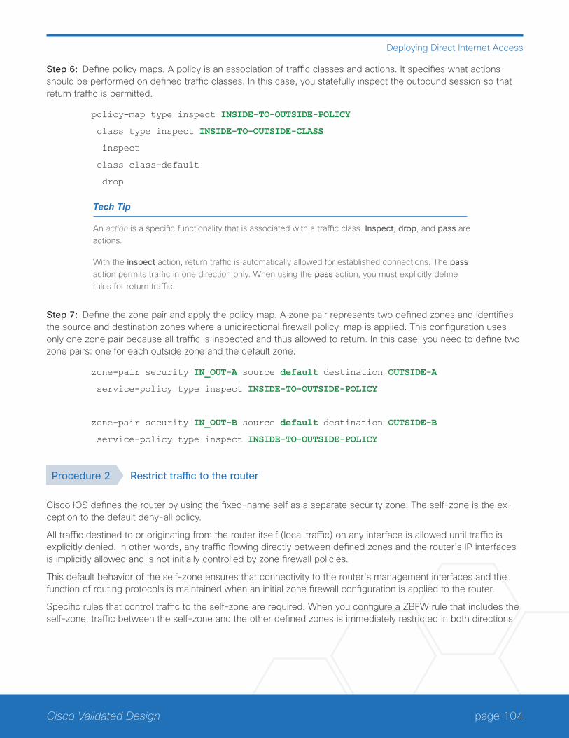
page 104Cisco Validated Design
Deploying Direct Internet Access
Step 6: Define policy maps. A policy is an association of traffic classes and actions. It specifies what actions should be performed on defined traffic classes. In this case, you statefully inspect the outbound session so that return traffic is permitted.
policy-map type inspect INSIDE-TO-OUTSIDE-POLICY
class type inspect INSIDE-TO-OUTSIDE-CLASS
inspect
class class-default
drop
Tech Tip
An action is a specific functionality that is associated with a traffic class. Inspect, drop, and pass are actions.
With the inspect action, return traffic is automatically allowed for established connections. The pass action permits traffic in one direction only. When using the pass action, you must explicitly define rules for return traffic.
Step 7: Define the zone pair and apply the policy map. A zone pair represents two defined zones and identifies the source and destination zones where a unidirectional firewall policy-map is applied. This configuration uses only one zone pair because all traffic is inspected and thus allowed to return. In this case, you need to define two zone pairs: one for each outside zone and the default zone.
zone-pair security IN_OUT-A source default destination OUTSIDE-A
service-policy type inspect INSIDE-TO-OUTSIDE-POLICY
zone-pair security IN_OUT-B source default destination OUTSIDE-B
service-policy type inspect INSIDE-TO-OUTSIDE-POLICY
Procedure 2 Restrict traffic to the router
Cisco IOS defines the router by using the fixed-name self as a separate security zone. The self-zone is the ex-ception to the default deny-all policy.
All traffic destined to or originating from the router itself (local traffic) on any interface is allowed until traffic is explicitly denied. In other words, any traffic flowing directly between defined zones and the router’s IP interfaces is implicitly allowed and is not initially controlled by zone firewall policies.
This default behavior of the self-zone ensures that connectivity to the router’s management interfaces and the function of routing protocols is maintained when an initial zone firewall configuration is applied to the router.
Specific rules that control traffic to the self-zone are required. When you configure a ZBFW rule that includes the self-zone, traffic between the self-zone and the other defined zones is immediately restricted in both directions.

page 105Cisco Validated Design
Deploying Direct Internet Access
Table 3 Self-zone firewall access list parameters
Protocol Stateful inspection policy
ISAKMP Yes
ICMP Yes
DHCP No
ESP No
GRE No
The following configuration allows the required traffic for proper remote-site router configuration with DMVPN. ESP and DHCP cannot be inspected and need to be configured with a pass action in the policy, using separate ACL and class-maps. ISAKMP should be configured with the inspect action and thus needs to be broken out with a separate ACL and class-maps for inbound and outbound policies.
Tech Tip
More specific ACLs than are shown here with the “any” keyword are recommended for added secu-rity.
Step 1: In the following steps, define access lists.
Step 2: Define an ACL allowing traffic with a destination of the router itself from the OUTSIDE zone. This includes ISAKMP for inbound tunnel initiation. This traffic can be inspected and is identified in the following ACL.
ip access-list extended ACL-RTR-IN
permit udp any any eq non500-isakmp
permit udp any any eq isakmp
permit icmp any any echo
permit icmp any any echo-reply
permit icmp any any ttl-exceeded
permit icmp any any port-unreachable
permit udp any any gt 1023 ttl eq 1
Step 3: Identify traffic for IPSEC tunnel initiation and other traffic that will originate from the router (self-zone) to the OUTSIDE zone. This traffic can be inspected.
ip access-list extended ACL-RTR-OUT
permit udp any any eq non500-isakmp
permit udp any any eq isakmp
permit icmp any any
permit udp any any eq domain

page 106Cisco Validated Design
Deploying Direct Internet Access
Tech Tip
The ICMP and domain entries here are for IPSLA probes that originate from the router.
permit icmp any any
permit udp any any eq domain
Step 4: Configure the DHCP ACL to allow the router to acquire a public IP address dynamically from the ISP. This traffic needs to be defined separately for server and client and cannot be inspected.
ip access-list extended DHCP-IN
permit udp any eq bootps any eq bootpc
ip access-list extended DHCP-OUT
permit udp any eq bootpc any eq bootps
Step 5: Configure the ESP ACL to allow the router to establish IPSEC communications for DMVPN. ESP needs to be explicitly allowed inbound and outbound in separate ACLs. ESP cannot be inspected.
ip access-list extended ESP-IN
permit esp any any
ip access-list extended ESP-OUT
permit esp any any
Step 6: Configure the GRE ACL to allow GRE tunnel formation. GRE needs to be explicitly allowed inbound only.
ip access-list extended GRE-IN
permit gre any any
Tech Tip
GRE needs to be permitted inbound for GRE on IOS-XE platforms due to a difference in interface order of operations. This is not required on IOS ISRG2 platforms.
Next, you define class maps for traffic to and from the self-zone. Separate class-maps are required for inbound and outbound initiated flows as well as for traffic that can be inspected by the router.
Step 7: Define the class-map matching inbound traffic that can be inspected.
class-map type inspect match-any INSPECT-ACL-IN-CLASS
match access-group name ACL-RTR-IN
Step 8: Define the class-map matching outbound traffic that can be inspected.
class-map type inspect match-any INSPECT-ACL-OUT-CLASS
match access-group name ACL-RTR-OUT

page 107Cisco Validated Design
Deploying Direct Internet Access
Step 9: Define the class-map matching inbound traffic that is not able to be inspected.
class-map type inspect match-any PASS-ACL-IN-CLASS
match access-group name ESP-IN
match access-group name DHCP-IN
match access-group name GRE-IN
Step 10: Define the class-map matching outbound traffic that cannot be inspected.
class-map type inspect match-any PASS-ACL-OUT-CLASS
match access-group name ESP-OUT
match access-group name DHCP-OUT
Next, you define policy maps. Create two separate policies, one for traffic inbound and one for traffic outbound.
Step 11: Define the inbound policy-map that refers to both of the outbound class-maps with actions of inspect, pass, and drop for the appropriate class defined.
policy-map type inspect ACL-IN-POLICY
class type inspect INSPECT-ACL-IN-CLASS
inspect
class type inspect PASS-ACL-IN-CLASS
pass
class class-default
drop
Step 12: Define the outbound policy-map that refers to both of the outbound class-maps with actions of inspect, pass, and drop for the appropriate class defined.
policy-map type inspect ACL-OUT-POLICY
class type inspect INSPECT-ACL-OUT-CLASS
inspect
class type inspect PASS-ACL-OUT-CLASS
pass
class class-default
drop
Tech Tip
Inspection for Layer 7 applications is not allowed for traffic going to and from the self-zone to other zones. Cisco IOS firewalls support only inspection of TCP, UDP, and H.323 traffic that terminates on or originates from the router itself.
Traffic such as DHCP and ESP cannot be inspected and must be configured as Pass in the associ-ated policy-map.

page 108Cisco Validated Design
Deploying Direct Internet Access
Next, you define the zone pair and apply policy maps to them.
Step 13: Define the zone pair for traffic destined to the self-zone of the router from the outside and associate the inbound policy-map defined in the previous step.
zone-pair security TO-ROUTER-A source OUTSIDE-A destination self
service-policy type inspect ACL-IN-POLICY
zone-pair security TO-ROUTER-B source OUTSIDE-B destination self
service-policy type inspect ACL-IN-POLICY
Step 14: Define the zone pair for traffic destined from the self-zone of the router to the outside and associate the outbound policy-map defined in the previous step.
zone-pair security FROM-ROUTER-A source self destination OUTSIDE-A
service-policy type inspect ACL-OUT-POLICY
zone-pair security FROM-ROUTER-B source self destination OUTSIDE-B
service-policy type inspect ACL-OUT-POLICY
Procedure 3 Enable and verify zone-based firewall configuration
Step 1: Assign the Internet-facing router interfaces to the outside security zone. All other interfaces are as-signed to the default zone and do not need to be defined.
interface GigabitEthernet0/0/0
description Internet Connection
zone-member security OUTSIDE-A
interface GigabitEthernet0/0/1
description Internet Connection
zone-member security OUTSIDE-B
Tech Tip
Interfaces in different VRFs cannot be assigned to the same security zone. In this case, each ISP interface must be in a different security zone.
An interface not defined as part of a security zone is automatically part of the “default” zone. In this configuration, all undefined interface DMVPN tunnels, transit sub-interfaces, and service interfaces such as Cisco UCS-E, and SRE interfaces are included as part of the default zone.
Loopback interfaces are members of the “self” zone and are not assigned to a defined security zone or the default zone.
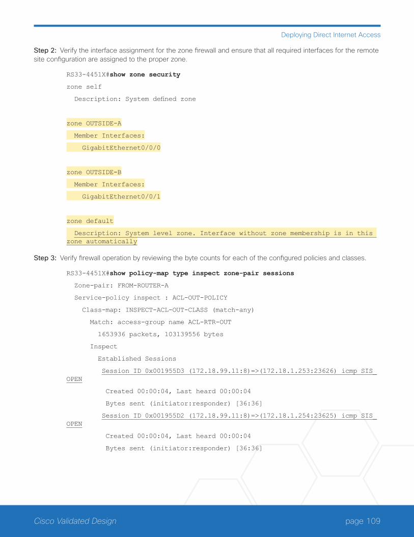
page 109Cisco Validated Design
Deploying Direct Internet Access
Step 2: Verify the interface assignment for the zone firewall and ensure that all required interfaces for the remote site configuration are assigned to the proper zone.
RS33-4451X#show zone security
zone self
Description: System defined zone
zone OUTSIDE-A
Member Interfaces:
GigabitEthernet0/0/0
zone OUTSIDE-B
Member Interfaces:
GigabitEthernet0/0/1
zone default
Description: System level zone. Interface without zone membership is in this zone automatically
Step 3: Verify firewall operation by reviewing the byte counts for each of the configured policies and classes.
RS33-4451X#show policy-map type inspect zone-pair sessions
Zone-pair: FROM-ROUTER-A
Service-policy inspect : ACL-OUT-POLICY
Class-map: INSPECT-ACL-OUT-CLASS (match-any)
Match: access-group name ACL-RTR-OUT
1653936 packets, 103139556 bytes
Inspect
Established Sessions
Session ID 0x001955D3 (172.18.99.11:8)=>(172.18.1.253:23626) icmp SIS_OPEN
Created 00:00:04, Last heard 00:00:04
Bytes sent (initiator:responder) [36:36]
Session ID 0x001955D2 (172.18.99.11:8)=>(172.18.1.254:23625) icmp SIS_OPEN
Created 00:00:04, Last heard 00:00:04
Bytes sent (initiator:responder) [36:36]
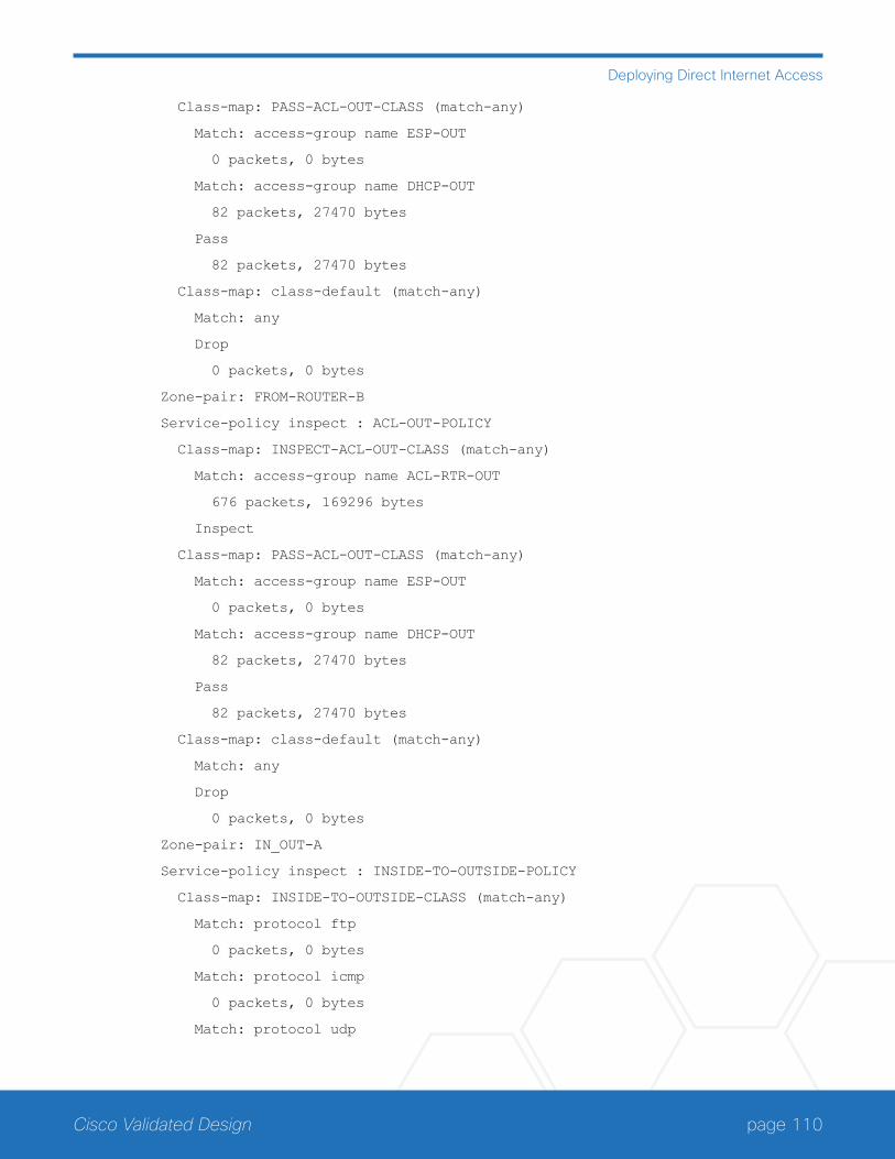
page 110Cisco Validated Design
Deploying Direct Internet Access
Class-map: PASS-ACL-OUT-CLASS (match-any)
Match: access-group name ESP-OUT
0 packets, 0 bytes
Match: access-group name DHCP-OUT
82 packets, 27470 bytes
Pass
82 packets, 27470 bytes
Class-map: class-default (match-any)
Match: any
Drop
0 packets, 0 bytes
Zone-pair: FROM-ROUTER-B
Service-policy inspect : ACL-OUT-POLICY
Class-map: INSPECT-ACL-OUT-CLASS (match-any)
Match: access-group name ACL-RTR-OUT
676 packets, 169296 bytes
Inspect
Class-map: PASS-ACL-OUT-CLASS (match-any)
Match: access-group name ESP-OUT
0 packets, 0 bytes
Match: access-group name DHCP-OUT
82 packets, 27470 bytes
Pass
82 packets, 27470 bytes
Class-map: class-default (match-any)
Match: any
Drop
0 packets, 0 bytes
Zone-pair: IN_OUT-A
Service-policy inspect : INSIDE-TO-OUTSIDE-POLICY
Class-map: INSIDE-TO-OUTSIDE-CLASS (match-any)
Match: protocol ftp
0 packets, 0 bytes
Match: protocol icmp
0 packets, 0 bytes
Match: protocol udp
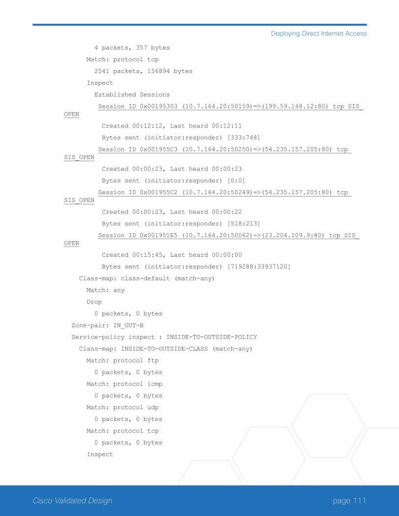
page 111Cisco Validated Design
Deploying Direct Internet Access
4 packets, 357 bytes
Match: protocol tcp
2541 packets, 156894 bytes
Inspect
Established Sessions
Session ID 0x00195303 (10.7.164.20:50159)=>(199.59.148.12:80) tcp SIS_OPEN
Created 00:12:12, Last heard 00:12:11
Bytes sent (initiator:responder) [333:748]
Session ID 0x001955C3 (10.7.164.20:50250)=>(54.235.157.205:80) tcp SIS_OPEN
Created 00:00:23, Last heard 00:00:23
Bytes sent (initiator:responder) [0:0]
Session ID 0x001955C2 (10.7.164.20:50249)=>(54.235.157.205:80) tcp SIS_OPEN
Created 00:00:23, Last heard 00:00:22
Bytes sent (initiator:responder) [518:213]
Session ID 0x001951E5 (10.7.164.20:50062)=>(23.204.109.9:80) tcp SIS_OPEN
Created 00:15:45, Last heard 00:00:00
Bytes sent (initiator:responder) [719288:33937120]
Class-map: class-default (match-any)
Match: any
Drop
0 packets, 0 bytes
Zone-pair: IN_OUT-B
Service-policy inspect : INSIDE-TO-OUTSIDE-POLICY
Class-map: INSIDE-TO-OUTSIDE-CLASS (match-any)
Match: protocol ftp
0 packets, 0 bytes
Match: protocol icmp
0 packets, 0 bytes
Match: protocol udp
0 packets, 0 bytes
Match: protocol tcp
0 packets, 0 bytes
Inspect

page 112Cisco Validated Design
Deploying Direct Internet Access
Class-map: class-default (match-any)
Match: any
Drop
0 packets, 0 bytes
Zone-pair: TO-ROUTER-A
Service-policy inspect : ACL-IN-POLICY
Class-map: INSPECT-ACL-IN-CLASS (match-any)
Match: access-group name ACL-RTR-IN
520 packets, 140828 bytes
Inspect
Class-map: PASS-ACL-IN-CLASS (match-any)
Match: access-group name ESP-IN
0 packets, 0 bytes
Match: access-group name DHCP-IN
82 packets, 28044 bytes
Match: access-group name GRE-IN
0 packets, 0 bytes
Pass
17880 packets, 3495146 bytes
Class-map: class-default (match-any)
Match: any
Drop
0 packets, 0 bytes
Zone-pair: TO-ROUTER-B
Service-policy inspect : ACL-IN-POLICY
Class-map: INSPECT-ACL-IN-CLASS (match-any)
Match: access-group name ACL-RTR-IN
522 packets, 142292 bytes
Inspect
Class-map: PASS-ACL-IN-CLASS (match-any)
Match: access-group name ESP-IN
0 packets, 0 bytes
Match: access-group name DHCP-IN
82 packets, 28044 bytes
Match: access-group name GRE-IN
0 packets, 0 bytes
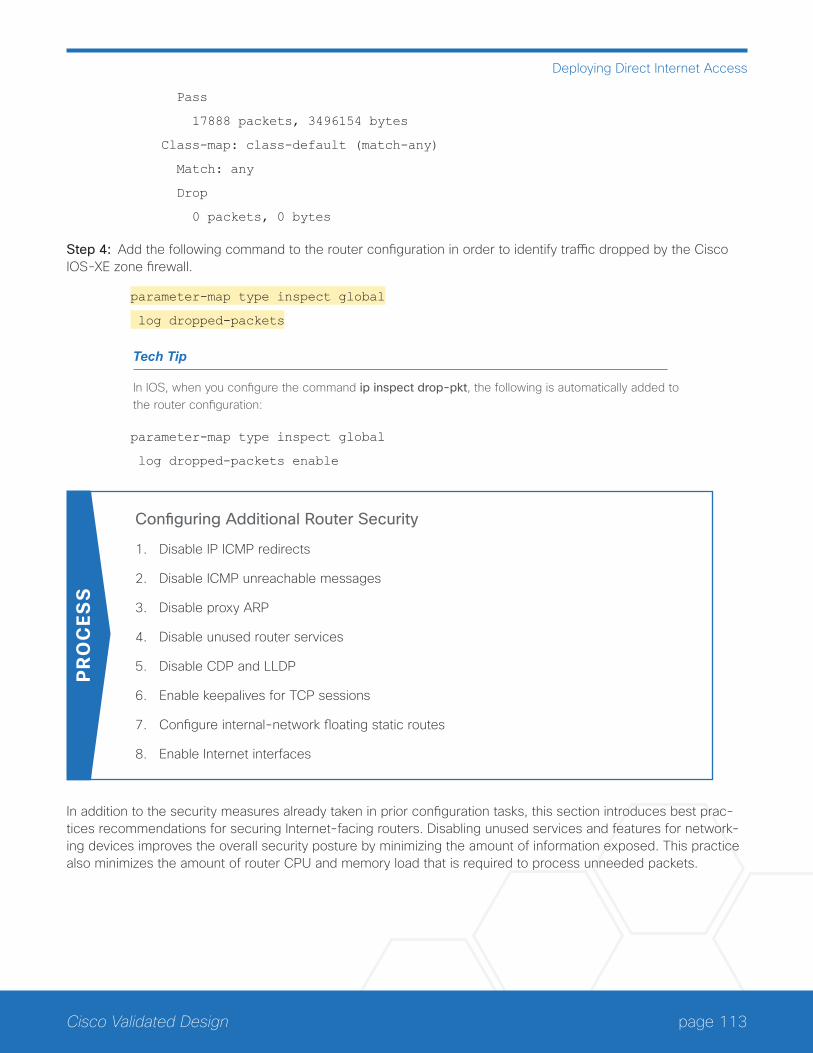
page 113Cisco Validated Design
Deploying Direct Internet Access
Pass
17888 packets, 3496154 bytes
Class-map: class-default (match-any)
Match: any
Drop
0 packets, 0 bytes
Step 4: Add the following command to the router configuration in order to identify traffic dropped by the Cisco IOS-XE zone firewall.
parameter-map type inspect global
log dropped-packets
Tech Tip
In IOS, when you configure the command ip inspect drop-pkt, the following is automatically added to the router configuration:
parameter-map type inspect global
log dropped-packets enable
Configuring Additional Router Security
1. Disable IP ICMP redirects
2. Disable ICMP unreachable messages
3. Disable proxy ARP
4. Disable unused router services
5. Disable CDP and LLDP
6. Enable keepalives for TCP sessions
7. Configure internal-network floating static routes
8. Enable Internet interfaces
PR
OC
ESS
In addition to the security measures already taken in prior configuration tasks, this section introduces best prac-tices recommendations for securing Internet-facing routers. Disabling unused services and features for network-ing devices improves the overall security posture by minimizing the amount of information exposed. This practice also minimizes the amount of router CPU and memory load that is required to process unneeded packets.
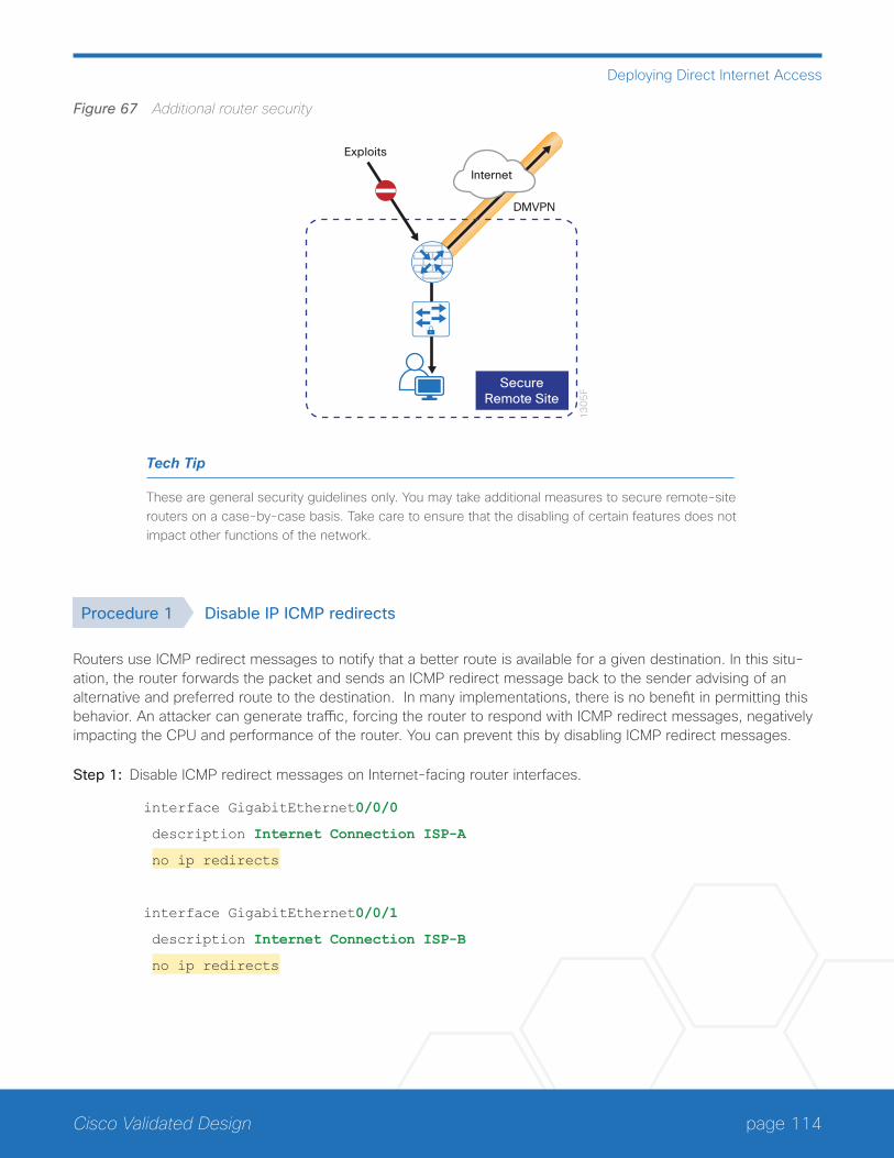
page 114Cisco Validated Design
Deploying Direct Internet Access
Figure 67 Additional router security
13
05
F
SecureRemote Site
DMVPN
Exploits
Internet
Tech Tip
These are general security guidelines only. You may take additional measures to secure remote-site routers on a case-by-case basis. Take care to ensure that the disabling of certain features does not impact other functions of the network.
Procedure 1 Disable IP ICMP redirects
Routers use ICMP redirect messages to notify that a better route is available for a given destination. In this situ-ation, the router forwards the packet and sends an ICMP redirect message back to the sender advising of an alternative and preferred route to the destination. In many implementations, there is no benefit in permitting this behavior. An attacker can generate traffic, forcing the router to respond with ICMP redirect messages, negatively impacting the CPU and performance of the router. You can prevent this by disabling ICMP redirect messages.
Step 1: Disable ICMP redirect messages on Internet-facing router interfaces.
interface GigabitEthernet0/0/0
description Internet Connection ISP-A
no ip redirects
interface GigabitEthernet0/0/1
description Internet Connection ISP-B
no ip redirects
page 115Cisco Validated Design
Deploying Direct Internet Access
Procedure 2 Disable ICMP unreachable messages
When filtering on router interfaces, routers send ICMP unreachable messages back to the source of blocked traf-fic. Generating these messages can increase CPU utilization on the router. By default, Cisco IOS ICMP unreach-able messages are limited to one every 500 milliseconds. ICMP unreachable messages can be disabled on a per interface basis.
Step 1: Disable ICMP unreachable messages on Internet-facing router interfaces.
interface GigabitEthernet0/0/0
description Internet Connection ISP-A
no ip unreachables
interface GigabitEthernet0/0/1
description Internet Connection ISP-B
no ip unreachables
Procedure 3 Disable proxy ARP
Proxy ARP allows the router to respond to ARP request for hosts other than itself. Proxy ARP can help machines on a subnet reach remote subnets without configuring routing or a default gateway as defined in RFC 1027. Dis-advantages to using proxy ARP:
• An attacker can impact available memory by sending a large number of ARP requests.
• A router is also susceptible to man-in-the-middle attacks where a host on the network could be used to spoof the MAC address of the router, resulting in unsuspecting hosts sending traffic to the attacker.
You can disable proxy ARP by using the interface configuration command.
Step 1: Disable proxy ARP on Internet-facing router interfaces.
interface GigabitEthernet0/0/0
description Internet Connection ISP-A
no ip proxy-arp
interface GigabitEthernet0/0/1
description Internet Connection ISP-B
no ip proxy-arp
page 116Cisco Validated Design
Deploying Direct Internet Access
Procedure 4 Disable unused router services
As a security best practice, you should disable all unnecessary services that could be used to launch DoS and other attacks. Many unused services that pose a security threat are disabled by default in current Cisco IOS ver-sions.
Step 1: Disable MOP on Internet-facing router interfaces.
interface GigabitEthernet0/0/0
description Internet Connection ISP-A
no mop enabled
interface GigabitEthernet0/0/1
description Internet Connection ISP-B
no mop enabled
Step 2: Disable PAD service globally on the router.
no service pad
Step 3: Prevent the router from attempting to locate a configuration file via TFTP globally on the router.
no service config
Procedure 5 Disable CDP and LLDP
Attackers can use CDP and LLDP for reconnaissance and network mapping. CDP is a network protocol that is used to discover other CDP-enabled devices. CDP is often used by NMS and for troubleshooting networking problems. LLDP is an IEEE protocol that is defined in 802.1AB and is very similar to CDP. You should disable CDP and LLDP on router interfaces that connect to untrusted networks.
Step 1: Disable CDP on Internet-facing router interfaces.
interface GigabitEthernet0/0/0
description Internet Connection ISP-A
no cdp enable
interface GigabitEthernet0/0/1
description Internet Connection ISP-B
no cdp enable
page 117Cisco Validated Design
Deploying Direct Internet Access
Step 2: Disable LLDP on Internet-facing router interfaces.
interface GigabitEthernet0/0/0
description Internet Connection ISP-A
no lldp transmit
no lldp receive
interface GigabitEthernet0/0/1
description Internet Connection ISP-B
no lldp transmit
no lldp receive
Procedure 6 Enable keepalives for TCP sessions
This configuration enables TCP keepalives on inbound connections to the router and outbound connections from the router. This ensures that the device on the remote end of the connection is still accessible and half-open or orphaned connections are removed from the router.
Step 1: Enable the TCP keepalives service for inbound and outbound connections globally on the router.
service tcp-keepalives-in
service tcp-keepalives-out
Procedure 7 Configure internal-network floating static routes
In the event the DMVPN tunnel to the hub site fails, you will want to ensure traffic destined to internal networks does not follow the local Internet default route. It’s best to have the network fail closed to prevent possible secu-rity implications and unwanted routing behavior.
Configuring floating static routes to null zero with an AD of 254 ensures that all internal subnets route to null0 in the event of tunnel failure.
Step 1: Configure static route for internal network subnets.
ip route 10.0.0.0 255.0.0.0 null0 254
Tech Tip
Configure the appropriate number of null 0 routes for internal network ranges, using summaries when possible for your specific network environment.
page 118Cisco Validated Design
Deploying Direct Internet Access
Procedure 8 Enable Internet interfaces
Now that the security configurations are complete, you can enable the Internet-facing interfaces.
Step 1: Enable the Internet-facing router interfaces.
interface GigabitEthernet0/0/0
description Internet Connection ISP-A
no shutdown
interface GigabitEthernet0/0/1
description Internet Connection ISP-B
no shutdown
Configuring ISP Black-Hole Routing Detection
1. Configure ISP black-hole routing detection
PR
OC
ESS
In many cases you will need to ensure connectivity issues with your ISP does not cause black-hole routing condi-tions. Failure conditions can exist where the DHCP address and routes are not removed from the remote-site router when connectivity issues exist with the broadband service or local premise equipment. There may also be circumstances if certain services are unreachable within via the local ISP connection that you want to reroute to a secondary Internet service.
If central Internet fallback is required, configure one or more of the following options.
Procedure 1 Configure ISP black-hole routing detection
Option 1: DMVPN Tunnel State Tracking
In this solution, the DMVPN tunnel state is used to monitor the status of the ISP connection used as the primary path for local Internet traffic. In this example, a “down” state of the tunnel interface triggers the removal of the default route via an EEM script. If tunnel state is “up” the route will remain.
Tech Tip
With this method, a failure or maintenance at the central site can cause a failover event where the route is removed due to tunnel state change and the local Internet connection remains active at the remote site.

page 119Cisco Validated Design
Deploying Direct Internet Access
Figure 68 IWAN tunnel tracking with EEM
12
97
F
VPN T
unne
l
TunnelState
Step 1: Ensure that state tracking is configured for the DMVPN tunnel interface.
interface Tunnel20
if-state nhrp
Step 2: Configure the tracking parameters and logic for the IPSLA probes.
track 80 interface Tunnel20 line-protocol
Step 3: Configure an EEM script to remove the local default route when the tunnel line protocol transitions to a “down” state.
event manager applet DISABLE-IWAN-DIA-DEFAULT
description ISP Black hole Detection - Tunnel state
event track 80 state down
action 1 cli command "enable"
action 2 cli command "configure terminal"
action 3 cli command "no ip route 0.0.0.0 0.0.0.0 GigabitEthernet0/0/0 dhcp 10"
action 4 cli command "end"
action 99 syslog msg "IWAN DIA DEFAULT IP ROUTE via GIG0/0/0 DISABLED"
Step 4: Configure an EEM script to restore the local default route when the tunnel line protocol transitions to an “up” state.
event manager applet ENABLE-IWAN-DIA-DEFAULT
description ISP Black hole Detection - Tunnel state
event track 80 state up
action 1 cli command "enable"
action 2 cli command "configure terminal"
action 3 cli command "ip route 0.0.0.0 0.0.0.0 GigabitEthernet0/0/0 dhcp 10"
action 4 cli command "end"
action 99 syslog msg "IWAN DIA DEFAULT IP ROUTE via GIG0/0/0 ENABLED"
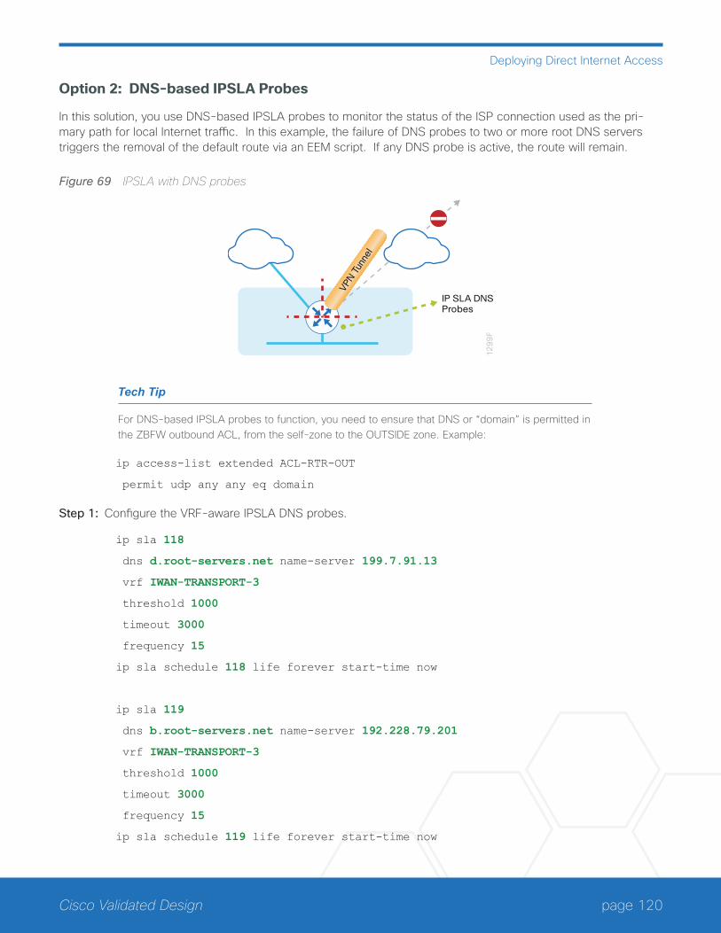
page 120Cisco Validated Design
Deploying Direct Internet Access
Option 2: DNS-based IPSLA Probes
In this solution, you use DNS-based IPSLA probes to monitor the status of the ISP connection used as the pri-mary path for local Internet traffic. In this example, the failure of DNS probes to two or more root DNS servers triggers the removal of the default route via an EEM script. If any DNS probe is active, the route will remain.
Figure 69 IPSLA with DNS probes
12
99
F
VPN T
unne
l
IP SLA DNSProbes
Tech Tip
For DNS-based IPSLA probes to function, you need to ensure that DNS or “domain” is permitted in the ZBFW outbound ACL, from the self-zone to the OUTSIDE zone. Example:
ip access-list extended ACL-RTR-OUT
permit udp any any eq domain
Step 1: Configure the VRF-aware IPSLA DNS probes.
ip sla 118
dns d.root-servers.net name-server 199.7.91.13
vrf IWAN-TRANSPORT-3
threshold 1000
timeout 3000
frequency 15
ip sla schedule 118 life forever start-time now
ip sla 119
dns b.root-servers.net name-server 192.228.79.201
vrf IWAN-TRANSPORT-3
threshold 1000
timeout 3000
frequency 15
ip sla schedule 119 life forever start-time now

page 121Cisco Validated Design
Deploying Direct Internet Access
Tech Tip
When configuring DNS probes, you should specify the hostname of the DNS server itself. That asks the DNS server to resolve for itself, allowing the use of root DNS servers.
Step 2: Configure the tracking parameters and logic for the IPSLA probes.
track 73 ip sla 118 reachability
track 74 ip sla 119 reachability
track 100 list boolean or
object 73
object 74
Step 3: Configure an EEM script to remove the route in the event of DNS probe failure.
event manager applet DISABLE-IWAN-DIA-DEFAULT
description ISP Black hole Detection - Tunnel state
event track 100 state down
action 1 cli command "enable"
action 2 cli command "configure terminal"
action 3 cli command "no ip route 0.0.0.0 0.0.0.0 GigabitEthernet0/0/0 dhcp 10"
action 4 cli command "end"
action 99 syslog msg "IWAN DIA DEFAULT IP ROUTE via GIG0/0/0 DISABLED"
Step 4: Configure an EEM script to also restore the local default route when the DNS probes are active.
event manager applet ENABLE-IWAN-DIA-DEFAULT
description ISP Black hole Detection - Tunnel state
event track 100 state up
action 1 cli command "enable"
action 2 cli command "configure terminal"
action 3 cli command "ip route 0.0.0.0 0.0.0.0 GigabitEthernet0/0/0 dhcp 10"
action 4 cli command "end"
action 99 syslog msg "IWAN DIA DEFAULT IP ROUTE via GIG0/0/0 ENABLED"

page 122Cisco Validated Design
Deploying Direct Internet Access
Option 3: IPSLA ICMP Probes
In this solution, you use IPSLA ICMP probes to monitor the status of the ISP connection used as the primary path for local Internet traffic. In this example, the failure of ICMP probes to two different IP hosts triggers the removal of the default route via an EEM script. If either ICMP probe is active, the route will remain.
Figure 70 IPSLA with ICMP probes
12
98
F
VPN T
unne
l
IP SLAProbes
Tech Tip
For ICMP-based IPSLA probes to function, you need to ensure ICMP is permitted in the outbound ACL, from the self-zone to the OUTSIDE zone.
Step 1: Configure the VRF-aware IPSLA ICMP probes.
ip sla 110
icmp-echo 172.18.1.253 source-interface GigabitEthernet0/0/0
vrf IWAN-TRANSPORT-3
threshold 1000
frequency 15
ip sla schedule 110 life forever start-time now
ip sla 111
icmp-echo 172.18.1.254 source-interface GigabitEthernet0/0/0
vrf IWAN-TRANSPORT-3
threshold 1000
frequency 15
ip sla schedule 111 life forever start-time now
page 123Cisco Validated Design
Deploying Direct Internet Access
Step 1: Configure the tracking parameters and logic for the IPSLA ICMP probes.
track 60 ip sla 110 reachability
track 61 ip sla 111 reachability
track 62 list boolean or
object 60
object 61
Step 2: Configure the EEM script to remove the route when the ICMP probes are down.
event manager applet DISABLE-IWAN-DIA-DEFAULT
description ISP Black hole Detection - Tunnel state
event track 62 state down
action 1 cli command "enable"
action 2 cli command "configure terminal"
action 3 cli command "no ip route 0.0.0.0 0.0.0.0 GigabitEthernet0/0/0 dhcp 10"
action 4 cli command "end"
action 99 syslog msg "IWAN DIA DEFAULT IP ROUTE via GIG0/0/0 DISABLED"
Step 3: Configure an EEM script to also restore the local default route when the ICMP probes are active.
event manager applet ENABLE-IWAN-DIA-DEFAULT
description ISP Black hole Detection - Tunnel state
event track 62 state up
action 1 cli command "enable"
action 2 cli command "configure terminal"
action 3 cli command "ip route 0.0.0.0 0.0.0.0 GigabitEthernet0/0/0 dhcp 10"
action 4 cli command "end"
action 99 syslog msg "IWAN DIA DEFAULT IP ROUTE via GIG0/0/0 ENABLED"
IWAN DUAL-ROUTER DUAL-INTERNET REMOTE SITE WITH DIAThis process describes configuring DIA for the dual-router dual-Internet IWAN design. These configurations as-sume the dual-router dual-Internet site with centralized Internet access is configured and functional as outlined in the Intelligent WAN Deployment Guide.
In this section, you convert a remote site from centralized Internet access for employees to a secure DIA configu-ration.
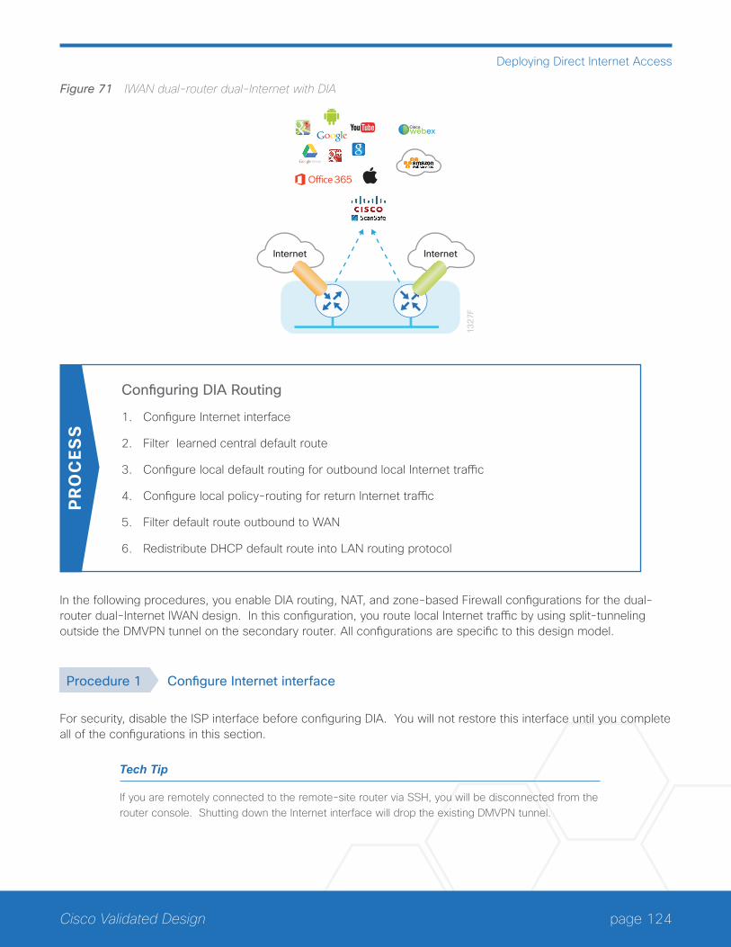
page 124Cisco Validated Design
Deploying Direct Internet Access
Figure 71 IWAN dual-router dual-Internet with DIA
13
27F
Internet Internet
Ciscowebex
Configuring DIA Routing
1. Configure Internet interface
2. Filter learned central default route
3. Configure local default routing for outbound local Internet traffic
4. Configure local policy-routing for return Internet traffic
5. Filter default route outbound to WAN
6. Redistribute DHCP default route into LAN routing protocol
PR
OC
ESS
In the following procedures, you enable DIA routing, NAT, and zone-based Firewall configurations for the dual-router dual-Internet IWAN design. In this configuration, you route local Internet traffic by using split-tunneling outside the DMVPN tunnel on the secondary router. All configurations are specific to this design model.
Procedure 1 Configure Internet interface
For security, disable the ISP interface before configuring DIA. You will not restore this interface until you complete all of the configurations in this section.
Tech Tip
If you are remotely connected to the remote-site router via SSH, you will be disconnected from the router console. Shutting down the Internet interface will drop the existing DMVPN tunnel.
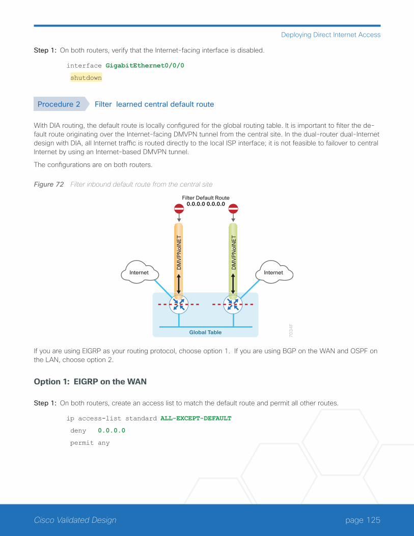
page 125Cisco Validated Design
Deploying Direct Internet Access
Step 1: On both routers, verify that the Internet-facing interface is disabled.
interface GigabitEthernet0/0/0
shutdown
Procedure 2 Filter learned central default route
With DIA routing, the default route is locally configured for the global routing table. It is important to filter the de-fault route originating over the Internet-facing DMVPN tunnel from the central site. In the dual-router dual-Internet design with DIA, all Internet traffic is routed directly to the local ISP interface; it is not feasible to failover to central Internet by using an Internet-based DMVPN tunnel.
The configurations are on both routers.
Figure 72 Filter inbound default route from the central site
70
34
F
DM
VP
No
INE
T
DM
VP
No
INE
T
Filter Default Route0.0.0.0 0.0.0.0
Global Table
InternetInternet
If you are using EIGRP as your routing protocol, choose option 1. If you are using BGP on the WAN and OSPF on the LAN, choose option 2.
Option 1: EIGRP on the WAN
Step 1: On both routers, create an access list to match the default route and permit all other routes.
ip access-list standard ALL-EXCEPT-DEFAULT
deny 0.0.0.0
permit any
page 126Cisco Validated Design
Deploying Direct Internet Access
Step 2: On both routers, create a route-map to reference the access list.
route-map BLOCK-DEFAULT permit 10
description Block only the default route inbound from the WAN
match ip address ALL-EXCEPT-DEFAULT
Step 3: On the primary router, apply the policy as an inbound distribute list for the Internet-facing DMVPN tunnel interface.
router eigrp IWAN-EIGRP
address-family ipv4 unicast autonomous-system 400
topology base
distribute-list route-map BLOCK-DEFAULT in tunnel20
exit-af-interface
exit-address-family
Step 4: On the secondary router, apply the policy as an inbound distribute list for the Internet-facing DMVPN tun-nel interface.
router eigrp IWAN-EIGRP
address-family ipv4 unicast autonomous-system 400
topology base
distribute-list route-map BLOCK-DEFAULT in tunnel21
exit-af-interface
exit-address-family
Option 2: BGP on the WAN
Step 1: On both routers, create an ip prefix-list to match the default route.
ip prefix-list ALL-EXCEPT-DEFAULT seq 10 permit 0.0.0.0/0
Step 2: On both routers, create a route-map to reference the ip prefix list.
route-map BLOCK-DEFAULT deny 10
description Block only the default route inbound from the WAN
match ip address prefix-list ALL-EXCEPT-DEFAULT
route-map BLOCK-DEFAULT permit 100
description Permit all other routes
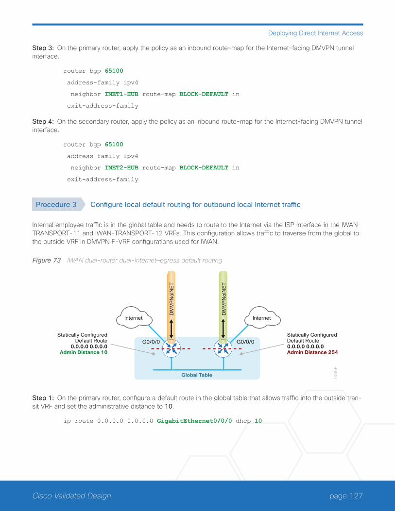
page 127Cisco Validated Design
Deploying Direct Internet Access
Step 3: On the primary router, apply the policy as an inbound route-map for the Internet-facing DMVPN tunnel interface.
router bgp 65100
address-family ipv4
neighbor INET1-HUB route-map BLOCK-DEFAULT in
exit-address-family
Step 4: On the secondary router, apply the policy as an inbound route-map for the Internet-facing DMVPN tunnel interface.
router bgp 65100
address-family ipv4
neighbor INET2-HUB route-map BLOCK-DEFAULT in
exit-address-family
Procedure 3 Configure local default routing for outbound local Internet traffic
Internal employee traffic is in the global table and needs to route to the Internet via the ISP interface in the IWAN-TRANSPORT-11 and IWAN-TRANSPORT-12 VRFs. This configuration allows traffic to traverse from the global to the outside VRF in DMVPN F-VRF configurations used for IWAN.
Figure 73 IWAN dual-router dual-Internet—egress default routing
70
35
F
DM
VP
No
INE
T
DM
VP
No
INE
T
Global Table
InternetInternet
Statically ConfiguredDefault Route0.0.0.0 0.0.0.0Admin Distance 254
Statically ConfiguredDefault Route
0.0.0.0 0.0.0.0Admin Distance 10
G0/0/0 G0/0/0
Step 1: On the primary router, configure a default route in the global table that allows traffic into the outside tran-sit VRF and set the administrative distance to 10.
ip route 0.0.0.0 0.0.0.0 GigabitEthernet0/0/0 dhcp 10
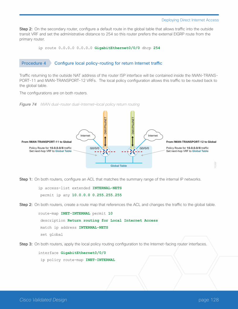
page 128Cisco Validated Design
Deploying Direct Internet Access
Step 2: On the secondary router, configure a default route in the global table that allows traffic into the outside transit VRF and set the administrative distance to 254 so this router prefers the external EIGRP route from the primary router.
ip route 0.0.0.0 0.0.0.0 GigabitEthernet0/0/0 dhcp 254
Procedure 4 Configure local policy-routing for return Internet traffic
Traffic returning to the outside NAT address of the router ISP interface will be contained inside the IWAN-TRANS-PORT-11 and IWAN-TRANSPORT-12 VRFs. The local policy configuration allows this traffic to be routed back to the global table.
The configurations are on both routers.
Figure 74 IWAN dual-router dual-Internet—local policy return routing
70
36
F
DM
VP
No
INE
T
DM
VP
No
INE
T
Global Table
InternetInternet
From IWAN-TRANSPORT-12 to Global
Policy Route for 10.0.0.0/8 trafficSet next-hop VRF to Global Table
From IWAN-TRANSPORT-11 to Global
Policy Route for 10.0.0.0/8 trafficSet next-hop VRF to Global Table
G0/0/0 G0/0/0
Step 1: On both routers, configure an ACL that matches the summary range of the internal IP networks.
ip access-list extended INTERNAL-NETS
permit ip any 10.0.0.0 0.255.255.255
Step 2: On both routers, create a route map that references the ACL and changes the traffic to the global table.
route-map INET-INTERNAL permit 10
description Return routing for Local Internet Access
match ip address INTERNAL-NETS
set global
Step 3: On both routers, apply the local policy routing configuration to the Internet-facing router interfaces.
interface GigabitEthernet0/0/0
ip policy route-map INET-INTERNAL

page 129Cisco Validated Design
Deploying Direct Internet Access
Procedure 5 Filter default route outbound to WAN
When you redistribute the default route into the routing protocol in the next procedure, it will be sent out the WAN interfaces to the central site location. This is not the desired behavior, so you must first configure an outbound filter.
Figure 75 IWAN dual-router dual-Internet—egress default route filtering
70
37
F
DM
VP
No
INE
T
DM
VP
No
INE
T
Global Table
InternetInternet
Filter Default Route0.0.0.0 0.0.0.0
If you are using EIGRP as your routing protocol, choose option 1. If you are using BGP on the WAN and OSPF on the LAN, choose option 2.
Option 1: EIGRP on the WAN
Step 1: On both routers, configure an access list to deny the default route and permit all other routes.
ip access-list standard ALL-EXCEPT-DEFAULT
deny 0.0.0.0
permit any
Step 2: On both routers, add an instance after the existing route map named “ROUTE-LIST” and reference the access list that denies the default route and permits all other routes. There should be an instance of this route map from the IWAN foundation configuration. This statement should go between the existing statements.
route-map ROUTE-LIST permit 20
description Block Local Internet Default route out to the WAN
match ip address ALL-EXCEPT-DEFAULT

page 130Cisco Validated Design
Deploying Direct Internet Access
Step 3: On the primary router, ensure that the route map is applied as an outbound distribution list on the DMVPN tunnel interface. Apply this as part of the foundational configuration for dual-router egress filtering.
router eigrp IWAN-EIGRP
address-family ipv4 unicast autonomous-system 400
topology base
distribute-list route-map ROUTE-LIST out Tunnel20
exit-af-topology
exit-address-family
Step 4: On the secondary router, ensure that the route map is applied as an outbound distribution list on the DM-VPN tunnel interface. Apply this as part of the foundational configuration for dual-router egress filtering.
router eigrp IWAN-EIGRP
address-family ipv4 unicast autonomous-system 400
topology base
distribute-list route-map ROUTE-LIST out Tunnel21
exit-af-topology
exit-address-family
Option 2: BGP on the WAN
Step 1: On both routers, create an ip prefix-list to match the default.
ip prefix-list ALL-EXCEPT-DEFAULT seq 10 permit 0.0.0.0/0
Step 2: On both routers, add an instance after the existing route map named “SPOKE-OUT” and reference the access list that denies the default route and permits all other routes. There should be an instance of this route map from the IWAN foundation configuration. These statements are added after the existing statements.
route-map SPOKE-OUT deny 20
description Block only the default route outbound from the WAN
match ip address prefix-list ALL-EXCEPT-DEFAULT
route-map SPOKE-OUT permit 1000
description Permit all other routes
Step 3: On the primary router, ensure the policy is applied as an outbound route-map for the DMVPN tunnel interface. Apply this as part of the foundational configuration for dual-router egress filtering.
router bgp 65100
address-family ipv4
neighbor INET1-HUB route-map SPOKE-OUT out
exit-address-family
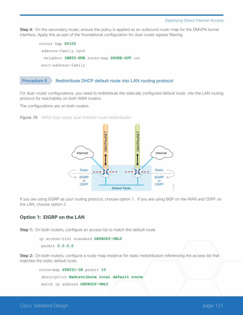
page 131Cisco Validated Design
Deploying Direct Internet Access
Step 4: On the secondary router, ensure the policy is applied as an outbound route-map for the DMVPN tunnel interface. Apply this as part of the foundational configuration for dual-router egress filtering.
router bgp 65100
address-family ipv4
neighbor INET2-HUB route-map SPOKE-OUT out
exit-address-family
Procedure 6 Redistribute DHCP default route into LAN routing protocol
For dual-router configurations, you need to redistribute the statically configured default route into the LAN routing protocol for reachability on both WAN routers.
The configurations are on both routers.
Figure 76 IWAN dual-router dual-Internet—route redistribution
70
38
F
DM
VP
No
INE
T
DM
VP
No
INE
T
Global Table
InternetInternet
Static
EIGRPor
OSPF
Static
EIGRPor
OSPF
If you are using EIGRP as your routing protocol, choose option 1. If you are using BGP on the WAN and OSPF on the LAN, choose option 2.
Option 1: EIGRP on the LAN
Step 1: On both routers, configure an access list to match the default route.
ip access-list standard DEFAULT-ONLY
permit 0.0.0.0
Step 2: On both routers, configure a route-map instance for static redistribution referencing the access list that matches the static default route.
route-map STATIC-IN permit 10
description Redistribute local default route
match ip address DEFAULT-ONLY

page 132Cisco Validated Design
Deploying Direct Internet Access
Step 3: On both routers, redistribute the static default route installed by DHCP into EIGRP AS400 by using the route map.
router eigrp IWAN-EIGRP
address-family ipv4 unicast autonomous-system 400
topology base
redistribute static route-map STATIC-IN
exit-af-topology
exit-address-family
Option 2: BGP on the WAN and OSPF on the LAN
Step 1: On both routers, configure an access list to match the default route for redistribution.
ip access-list standard DEFAULT-ONLY
permit 0.0.0.0
Step 2: On both routers, create a route-map to reference the ip access-list.
route-map STATIC-IN permit 10
description Redistribute local default route
match ip address DEFAULT-ONLY
Step 3: On both routers, redistribute the static default route from BGP to OSPF.
router bgp 65100
address-family ipv4
redistribute static route-map STATIC-IN
exit-address-family
Configuring Network Address Translation for DIA
1. Define and configure Cisco IOS NAT policy
PR
OC
ESS
In this design, inside hosts use RFC 1918 addresses, and traffic destined to the Internet from the local site needs to be translated to public IP space. The Internet-facing interface on the remote-site router uses DHCP to acquire a publically routable IP address; the NAT policy here will translate inside private IP addressed hosts to this DHCP address by using PAT.
This configuration is done on both the primary and secondary routers.

page 133Cisco Validated Design
Deploying Direct Internet Access
Figure 77 NAT for Internet Traffic
13
01
F
DMVPN
IP NATInside
Router withFirewall
IP NATOutside
CentralSite
SecureRemote Site NAT/PAT
Ciscowebex
Internet
Procedure 1 Define and configure Cisco IOS NAT policy
Use this procedure to configure NAT for DIA for dual-router dual-Internet remote-site configurations.
Step 1: Define a policy matching the desired traffic to be translated. Use an ACL and include all remote-site sub-nets used by employees.
ip access-list extended NAT-LOCAL
permit ip 10.7.176.0 0.0.7.255 any
Step 2: Configure route map to reference the ACL and match the outgoing Internet Interface.
route-map NAT permit 10
description Local Internet NAT
match ip address NAT-LOCAL
match interface GigabitEthernet0/0/0
Step 3: Configure the NAT policy.
ip nat inside source route-map NAT interface GigabitEthernet0/0/0 overload
Step 4: Enable NAT by applying policy to the inside router interfaces. Apply this configuration as needed to internal interfaces or sub-interfaces where traffic matching the ACL may originate, such as the data and transit networks and any service interfaces such as Cisco UCS-E or Cisco SRE interfaces.
interface Port-channel 1.64
description Data network
ip nat inside
interface Port-channel 1.99
description Transit network
ip nat inside
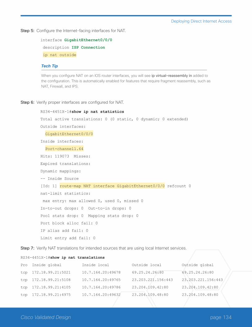
page 134Cisco Validated Design
Deploying Direct Internet Access
Step 5: Configure the Internet-facing interfaces for NAT.
interface GigabitEthernet0/0/0
description ISP Connection
ip nat outside
Tech Tip
When you configure NAT on an IOS router interfaces, you will see ip virtual-reassembly in added to the configuration. This is automatically enabled for features that require fragment reassembly, such as NAT, Firewall, and IPS.
Step 6: Verify proper interfaces are configured for NAT.
RS34-4451X-1#show ip nat statistics
Total active translations: 0 (0 static, 0 dynamic; 0 extended)
Outside interfaces:
GigabitEthernet0/0/0
Inside interfaces:
Port-channel1.64
Hits: 119073 Misses:
Expired translations:
Dynamic mappings:
-- Inside Source
[Id: 1] route-map NAT interface GigabitEthernet0/0/0 refcount 0
nat-limit statistics:
max entry: max allowed 0, used 0, missed 0
In-to-out drops: 0 Out-to-in drops: 0
Pool stats drop: 0 Mapping stats drop: 0
Port block alloc fail: 0
IP alias add fail: 0
Limit entry add fail: 0
Step 7: Verify NAT translations for intended sources that are using local Internet services.
RS34-4451X-1#show ip nat translations
Pro Inside global Inside local Outside local Outside global
tcp 172.18.99.21:5021 10.7.164.20:49678 69.25.24.26:80 69.25.24.26:80
tcp 172.18.99.21:5108 10.7.164.20:49765 23.203.221.156:443 23.203.221.156:443
tcp 172.18.99.21:4105 10.7.164.20:49786 23.204.109.42:80 23.204.109.42:80
tcp 172.18.99.21:4975 10.7.164.20:49632 23.204.109.48:80 23.204.109.48:80

page 135Cisco Validated Design
Deploying Direct Internet Access
Configuring Zone-Based Firewall for DIA
1. Configure base Cisco IOS Zone-Based Firewall parameters
2. Restrict traffic to the router
3. Enable and verify zone-based firewall configurationPR
OC
ESS
The following Cisco IOS firewall configuration is intended for use on Internet-facing remote site routers provid-ing secure local-Internet access. This configuration assumes DHCP and DMVPN are also configured to use the outside interface. To configure the required base firewall policies, complete the following procedures on both routers.
Follow these procedures to secure a dual-router dual-Internet remote-site router with direct Internet configura-tions.
Figure 78 Zone-based firewall for DIA
1304
F
CentralSite
SecureRemote Site
IOS ZoneFirewall
DMVPN
Security ZoneOUTSIDE
Security ZoneINSIDE
(default)
NAT/PAT
Internet
Ciscowebex

page 136Cisco Validated Design
Deploying Direct Internet Access
Procedure 1 Configure base Cisco IOS Zone-Based Firewall parameters
Step 1: If it is configured, remove the inbound ACL from the Internet-facing router interfaces, and then shut down the interface before continuing. This prevents unauthorized traffic while the ZBFW is configured.
interface GigabitEthernet0/0/0
shutdown
no ip access-list extended ACL-INET-PUBLIC in
Step 2: Define security zones. A zone is a named group of interfaces that have similar functions or security re-quirements. This example defines the names of the two basic security zones identified. For simplicity, this design uses the “default” security zone for inside interfaces. Once the default zone has been defined, all interfaces not explicitly configured as members of a security zone will automatically be part of the default security zone.
zone security default
zone security OUTSIDE
Tech Tip
This design uses the “default” zone for all inside interfaces; traffic can flow between all interfaces in the default zone.
An interface not defined as part of a security zone is automatically part of the “default” zone. In this configuration, all undefined interface DMVPN tunnels, transit sub-interfaces, and service interfaces such as Cisco UCS-E, and SRE interfaces are included as part of the default zone.
Be aware that any interface that is removed from a defined security zone will be automatically placed into the default zone. In this configuration, that interface will be treated as an “inside” zone and have access to the internal routing domain..
Step 3: Define a class map to match specific protocols. Class-maps apply match-any or match-all operators in order to determine how to apply the match criteria to the class. If match-any is specified, traffic must meet at least one of the match criteria in the class-map to be included in the class. If match-all is specified, traffic must meet all of the match criteria to be included in the class.
class-map type inspect match-any INSIDE-TO-OUTSIDE-CLASS
match protocol ftp
match protocol tcp
match protocol udp
match protocol icmp

page 137Cisco Validated Design
Deploying Direct Internet Access
Tech Tip
Protocols that use single ports (such as HTTP, telnet, SSH, etc.) can be statefully allowed with tcp inspection alone by using the match protocol tcp command.
Protocols such as ftp that use multiple ports (one for control and another for data) require application inspection in order to enable dynamic adjustments to the active firewall policy. The specific TCP ports that are required for the application are allowed for short durations, as necessary.
Step 4: Define policy maps. A policy is an association of traffic classes and actions. It specifies what actions should be performed on defined traffic classes. In this case, you statefully inspect the outbound session so that return traffic is permitted.
policy-map type inspect INSIDE-TO-OUTSIDE-POLICY
class type inspect INSIDE-TO-OUTSIDE-CLASS
inspect
class class-default
drop
Tech Tip
An action is a specific functionality that is associated with a traffic class. Inspect, drop, and pass are actions.
With the inspect action, return traffic is automatically allowed for established connections. The pass action permits traffic in one direction only. When using the pass action, you must explicitly define rules for return traffic.
Step 5: Define the zone pair and apply the policy map. A zone pair represents two defined zones and identifies the source and destination zones where a unidirectional firewall policy-map is applied. This configuration uses only one zone pair because all traffic is inspected and thus allowed to return.
zone-pair security IN_OUT source default destination OUTSIDE
service-policy type inspect INSIDE-TO-OUTSIDE-POLICY
Procedure 2 Restrict traffic to the router
Cisco IOS defines the router by using the fixed name self as a separate security zone. The self-zone is the ex-ception to the default deny-all policy.
All traffic destined to or originating from the router itself (local traffic) on any interface is allowed until traffic is explicitly denied. In other words, any traffic flowing directly between defined zones and the router’s IP interfaces is implicitly allowed and is not initially controlled by zone firewall policies.
This default behavior of the self-zone ensures that connectivity to the router’s management interfaces and the function of routing protocols is maintained when an initial zone firewall configuration is applied to the router.
Specific rules that control traffic to the self-zone are required. When you configure a ZBFW rule that includes the self-zone, traffic between the self-zone and the other defined zones is immediately restricted in both directions.
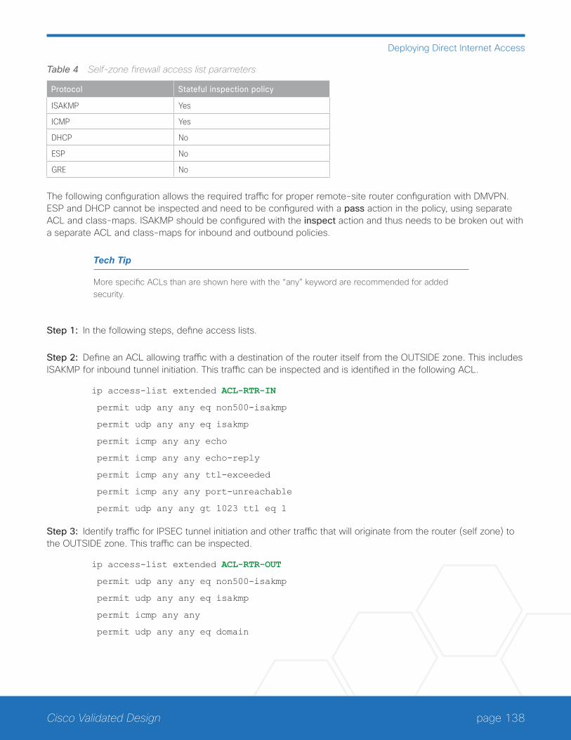
page 138Cisco Validated Design
Deploying Direct Internet Access
Table 4 Self-zone firewall access list parameters
Protocol Stateful inspection policy
ISAKMP Yes
ICMP Yes
DHCP No
ESP No
GRE No
The following configuration allows the required traffic for proper remote-site router configuration with DMVPN. ESP and DHCP cannot be inspected and need to be configured with a pass action in the policy, using separate ACL and class-maps. ISAKMP should be configured with the inspect action and thus needs to be broken out with a separate ACL and class-maps for inbound and outbound policies.
Tech Tip
More specific ACLs than are shown here with the “any” keyword are recommended for added security.
Step 1: In the following steps, define access lists.
Step 2: Define an ACL allowing traffic with a destination of the router itself from the OUTSIDE zone. This includes ISAKMP for inbound tunnel initiation. This traffic can be inspected and is identified in the following ACL.
ip access-list extended ACL-RTR-IN
permit udp any any eq non500-isakmp
permit udp any any eq isakmp
permit icmp any any echo
permit icmp any any echo-reply
permit icmp any any ttl-exceeded
permit icmp any any port-unreachable
permit udp any any gt 1023 ttl eq 1
Step 3: Identify traffic for IPSEC tunnel initiation and other traffic that will originate from the router (self zone) to the OUTSIDE zone. This traffic can be inspected.
ip access-list extended ACL-RTR-OUT
permit udp any any eq non500-isakmp
permit udp any any eq isakmp
permit icmp any any
permit udp any any eq domain
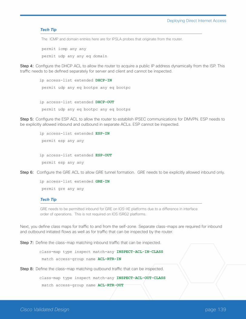
page 139Cisco Validated Design
Deploying Direct Internet Access
Tech Tip
The ICMP and domain entries here are for IPSLA probes that originate from the router.
permit icmp any any
permit udp any any eq domain
Step 4: Configure the DHCP ACL to allow the router to acquire a public IP address dynamically from the ISP. This traffic needs to be defined separately for server and client and cannot be inspected.
ip access-list extended DHCP-IN
permit udp any eq bootps any eq bootpc
ip access-list extended DHCP-OUT
permit udp any eq bootpc any eq bootps
Step 5: Configure the ESP ACL to allow the router to establish IPSEC communications for DMVPN. ESP needs to be explicitly allowed inbound and outbound in separate ACLs. ESP cannot be inspected.
ip access-list extended ESP-IN
permit esp any any
ip access-list extended ESP-OUT
permit esp any any
Step 6: Configure the GRE ACL to allow GRE tunnel formation. GRE needs to be explicitly allowed inbound only.
ip access-list extended GRE-IN
permit gre any any
Tech Tip
GRE needs to be permitted inbound for GRE on IOS-XE platforms due to a difference in interface order of operations. This is not required on IOS ISRG2 platforms.
Next, you define class maps for traffic to and from the self-zone. Separate class-maps are required for inbound and outbound initiated flows as well as for traffic that can be inspected by the router.
Step 7: Define the class-map matching inbound traffic that can be inspected.
class-map type inspect match-any INSPECT-ACL-IN-CLASS
match access-group name ACL-RTR-IN
Step 8: Define the class-map matching outbound traffic that can be inspected.
class-map type inspect match-any INSPECT-ACL-OUT-CLASS
match access-group name ACL-RTR-OUT
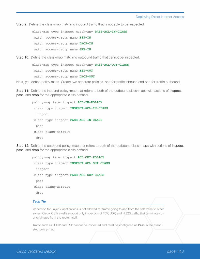
page 140Cisco Validated Design
Deploying Direct Internet Access
Step 9: Define the class-map matching inbound traffic that is not able to be inspected.
class-map type inspect match-any PASS-ACL-IN-CLASS
match access-group name ESP-IN
match access-group name DHCP-IN
match access-group name GRE-IN
Step 10: Define the class-map matching outbound traffic that cannot be inspected.
class-map type inspect match-any PASS-ACL-OUT-CLASS
match access-group name ESP-OUT
match access-group name DHCP-OUT
Next, you define policy maps. Create two separate policies, one for traffic inbound and one for traffic outbound.
Step 11: Define the inbound policy-map that refers to both of the outbound class-maps with actions of inspect, pass, and drop for the appropriate class defined.
policy-map type inspect ACL-IN-POLICY
class type inspect INSPECT-ACL-IN-CLASS
inspect
class type inspect PASS-ACL-IN-CLASS
pass
class class-default
drop
Step 12: Define the outbound policy-map that refers to both of the outbound class-maps with actions of inspect, pass, and drop for the appropriate class defined.
policy-map type inspect ACL-OUT-POLICY
class type inspect INSPECT-ACL-OUT-CLASS
inspect
class type inspect PASS-ACL-OUT-CLASS
pass
class class-default
drop
Tech Tip
Inspection for Layer 7 applications is not allowed for traffic going to and from the self-zone to other zones. Cisco IOS firewalls support only inspection of TCP, UDP, and H.323 traffic that terminates on or originates from the router itself.
Traffic such as DHCP and ESP cannot be inspected and must be configured as Pass in the associ-ated policy-map.
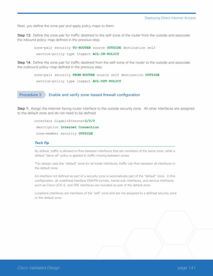
page 141Cisco Validated Design
Deploying Direct Internet Access
Next, you define the zone pair and apply policy maps to them.
Step 13: Define the zone pair for traffic destined to the self-zone of the router from the outside and associate the inbound policy-map defined in the previous step.
zone-pair security TO-ROUTER source OUTSIDE destination self
service-policy type inspect ACL-IN-POLICY
Step 14: Define the zone pair for traffic destined from the self-zone of the router to the outside and associate the outbound policy-map defined in the previous step.
zone-pair security FROM-ROUTER source self destination OUTSIDE
service-policy type inspect ACL-OUT-POLICY
Procedure 3 Enable and verify zone-based firewall configuration
Step 1: Assign the Internet-facing router interface to the outside security zone. All other interfaces are assigned to the default zone and do not need to be defined.
interface GigabitEthernet0/0/0
description Internet Connection
zone-member security OUTSIDE
Tech Tip
By default, traffic is allowed to flow between interfaces that are members of the same zone, while a default “deny-all” policy is applied to traffic moving between zones.
This design uses the “default” zone for all inside interfaces, traffic can flow between all interfaces in the default zone.
An interface not defined as part of a security zone is automatically part of the “default” zone. In this configuration, all undefined interface DMVPN tunnels, transit sub-interfaces, and service interfaces such as Cisco UCS-E, and SRE interfaces are included as part of the default zone.
Loopback interfaces are members of the “self” zone and are not assigned to a defined security zone or the default zone.
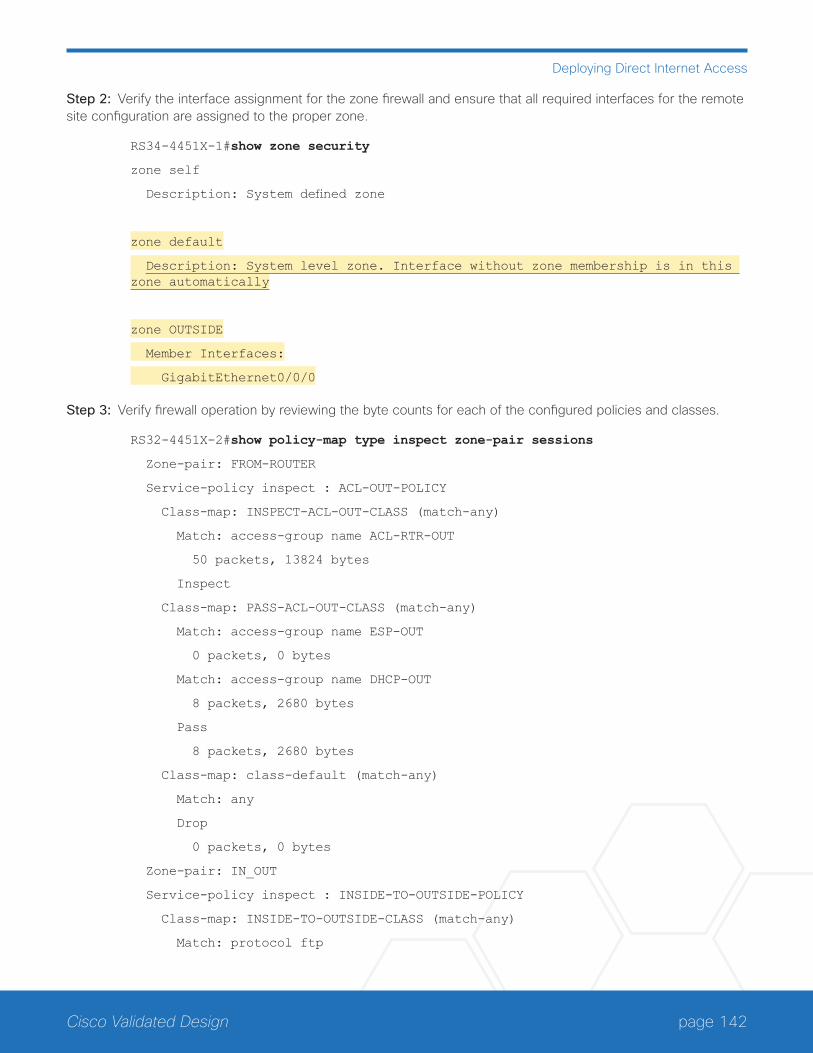
page 142Cisco Validated Design
Deploying Direct Internet Access
Step 2: Verify the interface assignment for the zone firewall and ensure that all required interfaces for the remote site configuration are assigned to the proper zone.
RS34-4451X-1#show zone security
zone self
Description: System defined zone
zone default
Description: System level zone. Interface without zone membership is in this zone automatically
zone OUTSIDE
Member Interfaces:
GigabitEthernet0/0/0
Step 3: Verify firewall operation by reviewing the byte counts for each of the configured policies and classes.
RS32-4451X-2#show policy-map type inspect zone-pair sessions
Zone-pair: FROM-ROUTER
Service-policy inspect : ACL-OUT-POLICY
Class-map: INSPECT-ACL-OUT-CLASS (match-any)
Match: access-group name ACL-RTR-OUT
50 packets, 13824 bytes
Inspect
Class-map: PASS-ACL-OUT-CLASS (match-any)
Match: access-group name ESP-OUT
0 packets, 0 bytes
Match: access-group name DHCP-OUT
8 packets, 2680 bytes
Pass
8 packets, 2680 bytes
Class-map: class-default (match-any)
Match: any
Drop
0 packets, 0 bytes
Zone-pair: IN_OUT
Service-policy inspect : INSIDE-TO-OUTSIDE-POLICY
Class-map: INSIDE-TO-OUTSIDE-CLASS (match-any)
Match: protocol ftp
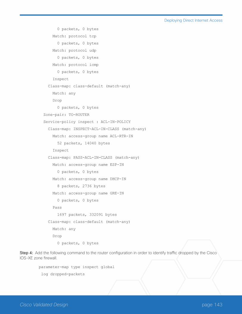
page 143Cisco Validated Design
Deploying Direct Internet Access
0 packets, 0 bytes
Match: protocol tcp
0 packets, 0 bytes
Match: protocol udp
0 packets, 0 bytes
Match: protocol icmp
0 packets, 0 bytes
Inspect
Class-map: class-default (match-any)
Match: any
Drop
0 packets, 0 bytes
Zone-pair: TO-ROUTER
Service-policy inspect : ACL-IN-POLICY
Class-map: INSPECT-ACL-IN-CLASS (match-any)
Match: access-group name ACL-RTR-IN
52 packets, 14040 bytes
Inspect
Class-map: PASS-ACL-IN-CLASS (match-any)
Match: access-group name ESP-IN
0 packets, 0 bytes
Match: access-group name DHCP-IN
8 packets, 2736 bytes
Match: access-group name GRE-IN
0 packets, 0 bytes
Pass
1697 packets, 332091 bytes
Class-map: class-default (match-any)
Match: any
Drop
0 packets, 0 bytes
Step 4: Add the following command to the router configuration in order to identify traffic dropped by the Cisco IOS-XE zone firewall.
parameter-map type inspect global
log dropped-packets

page 144Cisco Validated Design
Deploying Direct Internet Access
Tech Tip
In IOS, when you configure the command ip inspect drop-pkt, the following is automatically added to the router configuration:
parameter-map type inspect global
log dropped-packets enable
Configuring Additional Router Security
1. Disable IP ICMP redirects
2. Disable ICMP unreachable messages
3. Disable Proxy ARP
4. Disable unused router services
5. Disable CDP and LLDP
6. Enable keepalives for TCP sessions
7. Configure internal-network floating static routes
8. Enable Internet interfaces
PR
OC
ESS
In addition to the security measures already taken in prior configuration tasks, this section introduces best prac-tices recommendations to secure Internet-facing routers. Disabling unused services and features for networking devices improves the overall security posture by minimizing the amount of information exposed. This practice also minimizes the amount of router CPU and memory load that is required to process unneeded packets.
Figure 79 Additional router security
13
05
F
SecureRemote Site
DMVPN
Exploits
Internet
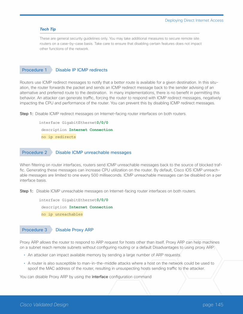
page 145Cisco Validated Design
Deploying Direct Internet Access
Tech Tip
These are general security guidelines only. You may take additional measures to secure remote site routers on a case-by-case basis. Take care to ensure that disabling certain features does not impact other functions of the network.
Procedure 1 Disable IP ICMP redirects
Routers use ICMP redirect messages to notify that a better route is available for a given destination. In this situ-ation, the router forwards the packet and sends an ICMP redirect message back to the sender advising of an alternative and preferred route to the destination. In many implementations, there is no benefit in permitting this behavior. An attacker can generate traffic, forcing the router to respond with ICMP redirect messages, negatively impacting the CPU and performance of the router. You can prevent this by disabling ICMP redirect messages.
Step 1: Disable ICMP redirect messages on Internet-facing router interfaces on both routers.
interface GigabitEthernet0/0/0
description Internet Connection
no ip redirects
Procedure 2 Disable ICMP unreachable messages
When filtering on router interfaces, routers send ICMP unreachable messages back to the source of blocked traf-fic. Generating these messages can increase CPU utilization on the router. By default, Cisco IOS ICMP unreach-able messages are limited to one every 500 milliseconds. ICMP unreachable messages can be disabled on a per interface basis.
Step 1: Disable ICMP unreachable messages on Internet-facing router interfaces on both routers.
interface GigabitEthernet0/0/0
description Internet Connection
no ip unreachables
Procedure 3 Disable Proxy ARP
Proxy ARP allows the router to respond to ARP request for hosts other than itself. Proxy ARP can help machines on a subnet reach remote subnets without configuring routing or a default Disadvantages to using proxy ARP:
• An attacker can impact available memory by sending a large number of ARP requests.
• A router is also susceptible to man-in-the-middle attacks where a host on the network could be used to spoof the MAC address of the router, resulting in unsuspecting hosts sending traffic to the attacker.
You can disable Proxy ARP by using the interface configuration command
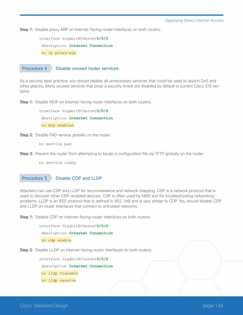
page 146Cisco Validated Design
Deploying Direct Internet Access
Step 1: Disable proxy ARP on Internet-facing router interfaces on both routers.
interface GigabitEthernet0/0/0
description Internet Connection
no ip proxy-arp
Procedure 4 Disable unused router services
As a security best practice, you should disable all unnecessary services that could be used to launch DoS and other attacks. Many unused services that pose a security threat are disabled by default in current Cisco IOS ver-sions.
Step 1: Disable MOP on Internet-facing router interfaces on both routers.
interface GigabitEthernet0/0/0
description Internet Connection
no mop enabled
Step 2: Disable PAD service globally on the router.
no service pad
Step 3: Prevent the router from attempting to locate a configuration file via TFTP globally on the router.
no service config
Procedure 5 Disable CDP and LLDP
Attackers can use CDP and LLDP for reconnaissance and network mapping. CDP is a network protocol that is used to discover other CDP-enabled devices. CDP is often used by NMS and for troubleshooting networking problems. LLDP is an IEEE protocol that is defined in 802.1AB and is very similar to CDP. You should disable CDP and LLDP on router interfaces that connect to untrusted networks.
Step 1: Disable CDP on Internet-facing router interfaces on both routers.
interface GigabitEthernet0/0/0
description Internet Connection
no cdp enable
Step 2: Disable LLDP on Internet-facing router interfaces on both routers.
interface GigabitEthernet0/0/0
description Internet Connection
no lldp transmit
no lldp receive
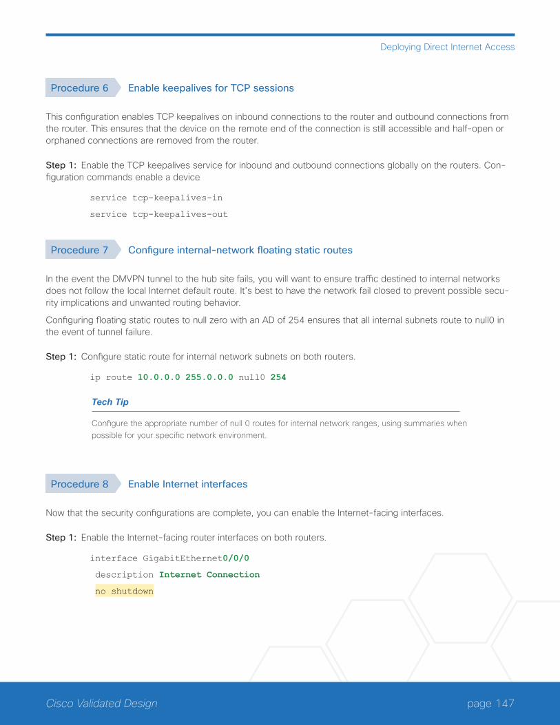
page 147Cisco Validated Design
Deploying Direct Internet Access
Procedure 6 Enable keepalives for TCP sessions
This configuration enables TCP keepalives on inbound connections to the router and outbound connections from the router. This ensures that the device on the remote end of the connection is still accessible and half-open or orphaned connections are removed from the router.
Step 1: Enable the TCP keepalives service for inbound and outbound connections globally on the routers. Con-figuration commands enable a device
service tcp-keepalives-in
service tcp-keepalives-out
Procedure 7 Configure internal-network floating static routes
In the event the DMVPN tunnel to the hub site fails, you will want to ensure traffic destined to internal networks does not follow the local Internet default route. It’s best to have the network fail closed to prevent possible secu-rity implications and unwanted routing behavior.
Configuring floating static routes to null zero with an AD of 254 ensures that all internal subnets route to null0 in the event of tunnel failure.
Step 1: Configure static route for internal network subnets on both routers.
ip route 10.0.0.0 255.0.0.0 null0 254
Tech Tip
Configure the appropriate number of null 0 routes for internal network ranges, using summaries when possible for your specific network environment.
Procedure 8 Enable Internet interfaces
Now that the security configurations are complete, you can enable the Internet-facing interfaces.
Step 1: Enable the Internet-facing router interfaces on both routers.
interface GigabitEthernet0/0/0
description Internet Connection
no shutdown
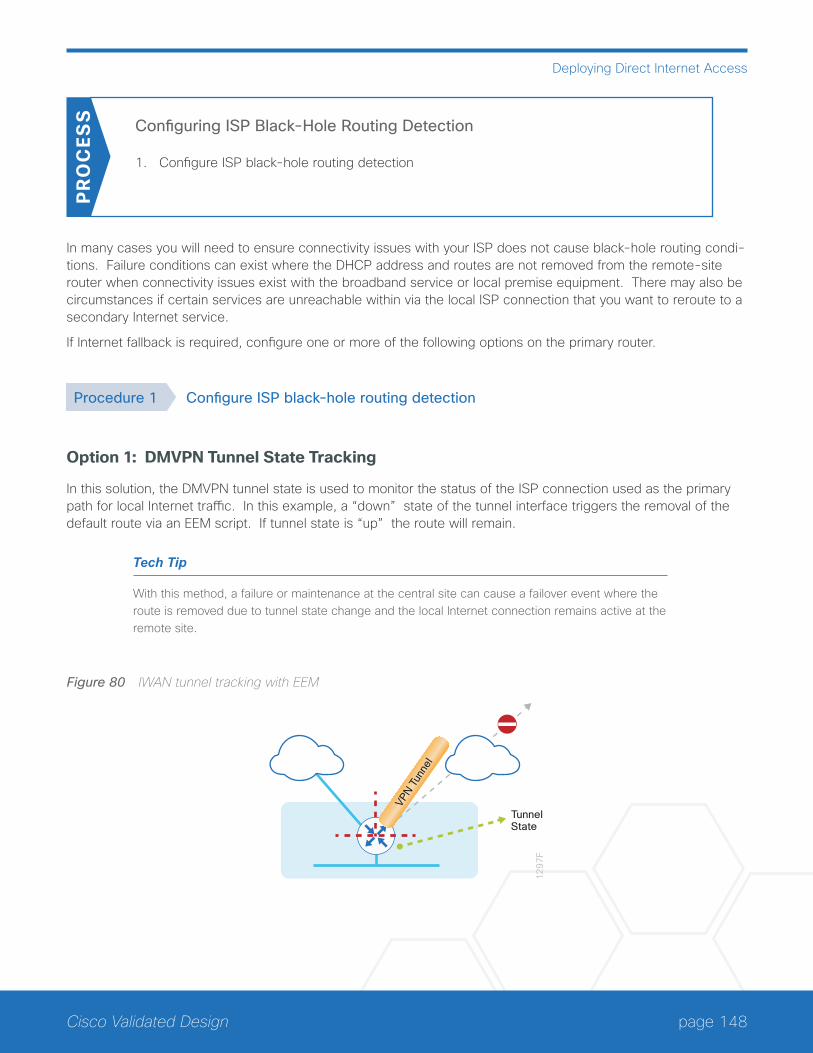
page 148Cisco Validated Design
Deploying Direct Internet Access
Configuring ISP Black-Hole Routing Detection
1. Configure ISP black-hole routing detection
PR
OC
ESS
In many cases you will need to ensure connectivity issues with your ISP does not cause black-hole routing condi-tions. Failure conditions can exist where the DHCP address and routes are not removed from the remote-site router when connectivity issues exist with the broadband service or local premise equipment. There may also be circumstances if certain services are unreachable within via the local ISP connection that you want to reroute to a secondary Internet service.
If Internet fallback is required, configure one or more of the following options on the primary router.
Procedure 1 Configure ISP black-hole routing detection
Option 1: DMVPN Tunnel State Tracking
In this solution, the DMVPN tunnel state is used to monitor the status of the ISP connection used as the primary path for local Internet traffic. In this example, a “down” state of the tunnel interface triggers the removal of the default route via an EEM script. If tunnel state is “up” the route will remain.
Tech Tip
With this method, a failure or maintenance at the central site can cause a failover event where the route is removed due to tunnel state change and the local Internet connection remains active at the remote site.
Figure 80 IWAN tunnel tracking with EEM
12
97
F
VPN T
unne
l
TunnelState
page 149Cisco Validated Design
Deploying Direct Internet Access
Step 1: Ensure that state tracking is configured for the DMVPN tunnel interface on the primary router.
interface Tunnel20
if-state nhrp
Step 2: Configure the tracking parameters and logic for the IPSLA probes on the primary router.
track 80 interface Tunnel20 line-protocol
Step 3: On the primary router, configure an EEM script to remove the local default route when the tunnel line pro-tocol transitions to a “down” state.
event manager applet DISABLE-IWAN-DIA-DEFAULT
description ISP Black hole Detection - Tunnel state
event track 80 state down
action 1 cli command "enable"
action 2 cli command "configure terminal"
action 3 cli command "no ip route 0.0.0.0 0.0.0.0 GigabitEthernet0/0/0 dhcp 10"
action 4 cli command "end"
action 99 syslog msg "IWAN DIA DEFAULT IP ROUTE via GIG0/0/0 DISABLED"
Step 4: On the primary router, configure an EEM script to also restore the local default route when the tunnel line protocol transitions to an “up” state.
event manager applet ENABLE-IWAN-DIA-DEFAULT
description ISP Black hole Detection - Tunnel state
event track 80 state up
action 1 cli command "enable"
action 2 cli command "configure terminal"
action 3 cli command "ip route 0.0.0.0 0.0.0.0 GigabitEthernet0/0/0 dhcp 10"
action 4 cli command "end"
action 99 syslog msg "IWAN DIA DEFAULT IP ROUTE via GIG0/0/0 ENABLED"
Option 2: DNS-Based IPSLA Probes
In this solution, you use DNS-based IPSLA probes to monitor the status of the ISP connection used as the pri-mary path for local Internet traffic. In this example, the failure of DNS probes to two or more root DNS servers triggers the removal of the default route via an EEM script. If any DNS probe is active, the route will remain.
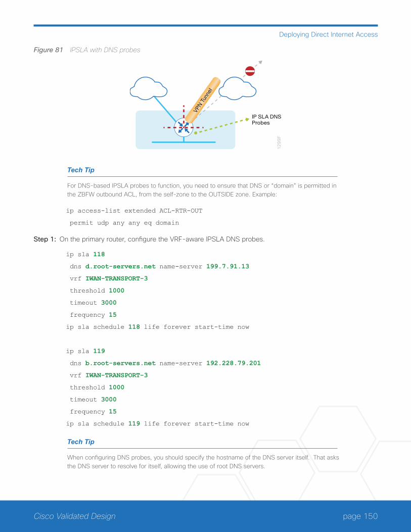
page 150Cisco Validated Design
Deploying Direct Internet Access
Figure 81 IPSLA with DNS probes
12
99
F
VPN T
unne
l
IP SLA DNSProbes
Tech Tip
For DNS-based IPSLA probes to function, you need to ensure that DNS or “domain” is permitted in the ZBFW outbound ACL, from the self-zone to the OUTSIDE zone. Example:
ip access-list extended ACL-RTR-OUT
permit udp any any eq domain
Step 1: On the primary router, configure the VRF-aware IPSLA DNS probes.
ip sla 118
dns d.root-servers.net name-server 199.7.91.13
vrf IWAN-TRANSPORT-3
threshold 1000
timeout 3000
frequency 15
ip sla schedule 118 life forever start-time now
ip sla 119
dns b.root-servers.net name-server 192.228.79.201
vrf IWAN-TRANSPORT-3
threshold 1000
timeout 3000
frequency 15
ip sla schedule 119 life forever start-time now
Tech Tip
When configuring DNS probes, you should specify the hostname of the DNS server itself. That asks the DNS server to resolve for itself, allowing the use of root DNS servers.
page 151Cisco Validated Design
Deploying Direct Internet Access
Step 2: On the primary router, configure the tracking parameters and logic for the IPSLA probes.
track 73 ip sla 118 reachability
track 74 ip sla 119 reachability
!
track 100 list boolean or
object 73
object 74
Step 3: On the primary router, configure an EEM script to remove the local default route in the event of DNS probe failure.
event manager applet DISABLE-IWAN-DIA-DEFAULT
description ISP Black hole Detection - Tunnel state
event track 100 state down
action 1 cli command "enable"
action 2 cli command "configure terminal"
action 3 cli command "no ip route 0.0.0.0 0.0.0.0 GigabitEthernet0/0/0 dhcp 10"
action 4 cli command "end"
action 99 syslog msg "IWAN DIA DEFAULT IP ROUTE via GIG0/0/0 DISABLED"
Step 4: On the primary router, configure an EEM script to also restore the local default route when the DNS probes are active.
event manager applet ENABLE-IWAN-DIA-DEFAULT
description ISP Black hole Detection - Tunnel state
event track 100 state up
action 1 cli command "enable"
action 2 cli command "configure terminal"
action 3 cli command "ip route 0.0.0.0 0.0.0.0 GigabitEthernet0/0/0 dhcp 10"
action 4 cli command "end"
action 99 syslog msg "IWAN DIA DEFAULT IP ROUTE via GIG0/0/0 ENABLED"
Option 3: IPSLA ICMP Probes
In this solution, you use IPSLA ICMP probes to monitor the status of the ISP connection used as the primary path for local Internet traffic. In this example, the failure of ICMP probes to two different IP hosts triggers the removal of the default route via an EEM script. If either ICMP probe is active the route will remain.
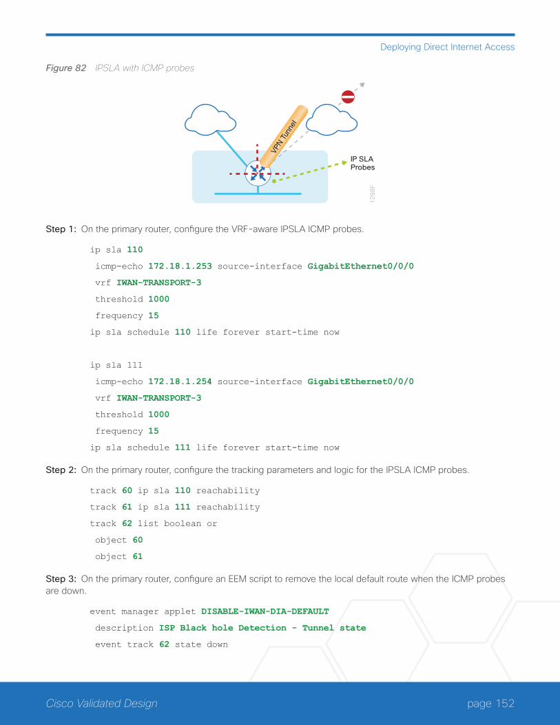
page 152Cisco Validated Design
Deploying Direct Internet Access
Figure 82 IPSLA with ICMP probes
12
98
F
VPN T
unne
l
IP SLAProbes
Step 1: On the primary router, configure the VRF-aware IPSLA ICMP probes.
ip sla 110
icmp-echo 172.18.1.253 source-interface GigabitEthernet0/0/0
vrf IWAN-TRANSPORT-3
threshold 1000
frequency 15
ip sla schedule 110 life forever start-time now
ip sla 111
icmp-echo 172.18.1.254 source-interface GigabitEthernet0/0/0
vrf IWAN-TRANSPORT-3
threshold 1000
frequency 15
ip sla schedule 111 life forever start-time now
Step 2: On the primary router, configure the tracking parameters and logic for the IPSLA ICMP probes.
track 60 ip sla 110 reachability
track 61 ip sla 111 reachability
track 62 list boolean or
object 60
object 61
Step 3: On the primary router, configure an EEM script to remove the local default route when the ICMP probes are down.
event manager applet DISABLE-IWAN-DIA-DEFAULT
description ISP Black hole Detection - Tunnel state
event track 62 state down
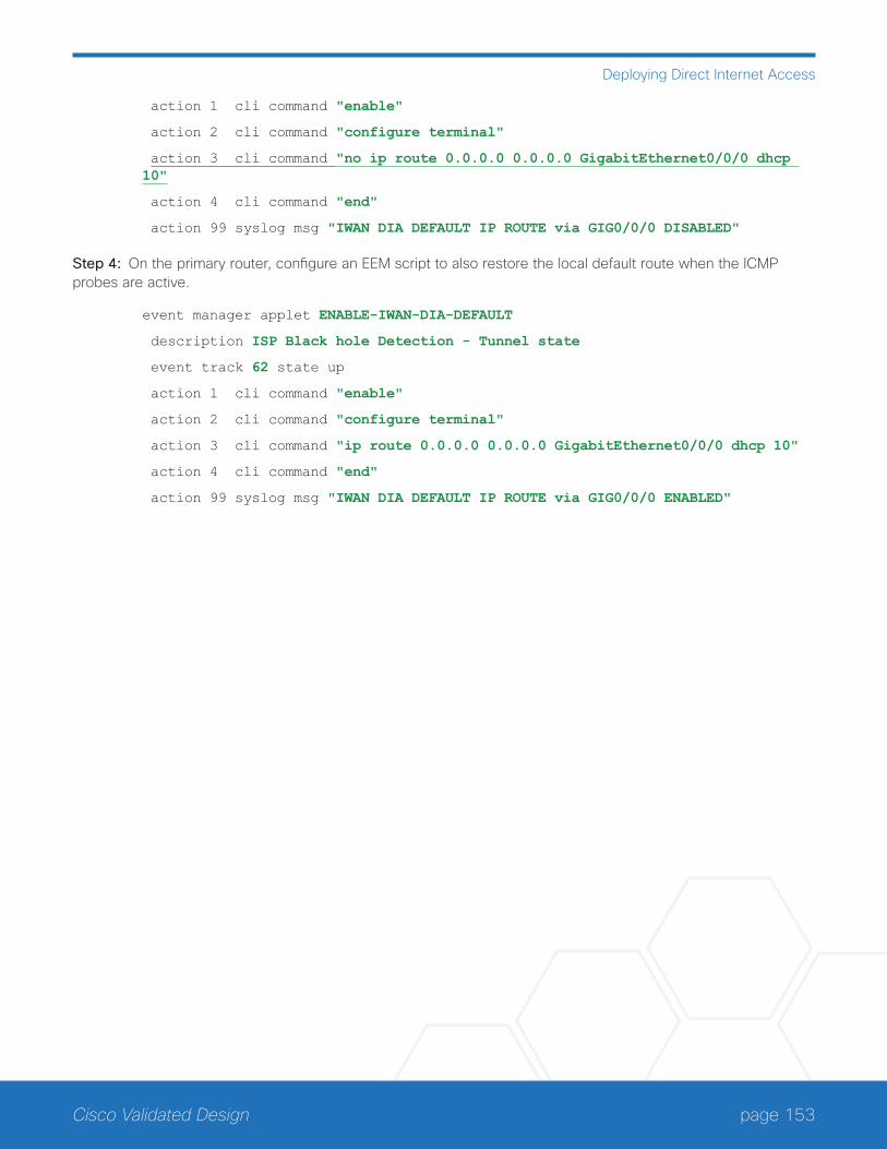
page 153Cisco Validated Design
Deploying Direct Internet Access
action 1 cli command "enable"
action 2 cli command "configure terminal"
action 3 cli command "no ip route 0.0.0.0 0.0.0.0 GigabitEthernet0/0/0 dhcp 10"
action 4 cli command "end"
action 99 syslog msg "IWAN DIA DEFAULT IP ROUTE via GIG0/0/0 DISABLED"
Step 4: On the primary router, configure an EEM script to also restore the local default route when the ICMP probes are active.
event manager applet ENABLE-IWAN-DIA-DEFAULT
description ISP Black hole Detection - Tunnel state
event track 62 state up
action 1 cli command "enable"
action 2 cli command "configure terminal"
action 3 cli command "ip route 0.0.0.0 0.0.0.0 GigabitEthernet0/0/0 dhcp 10"
action 4 cli command "end"
action 99 syslog msg "IWAN DIA DEFAULT IP ROUTE via GIG0/0/0 ENABLED"
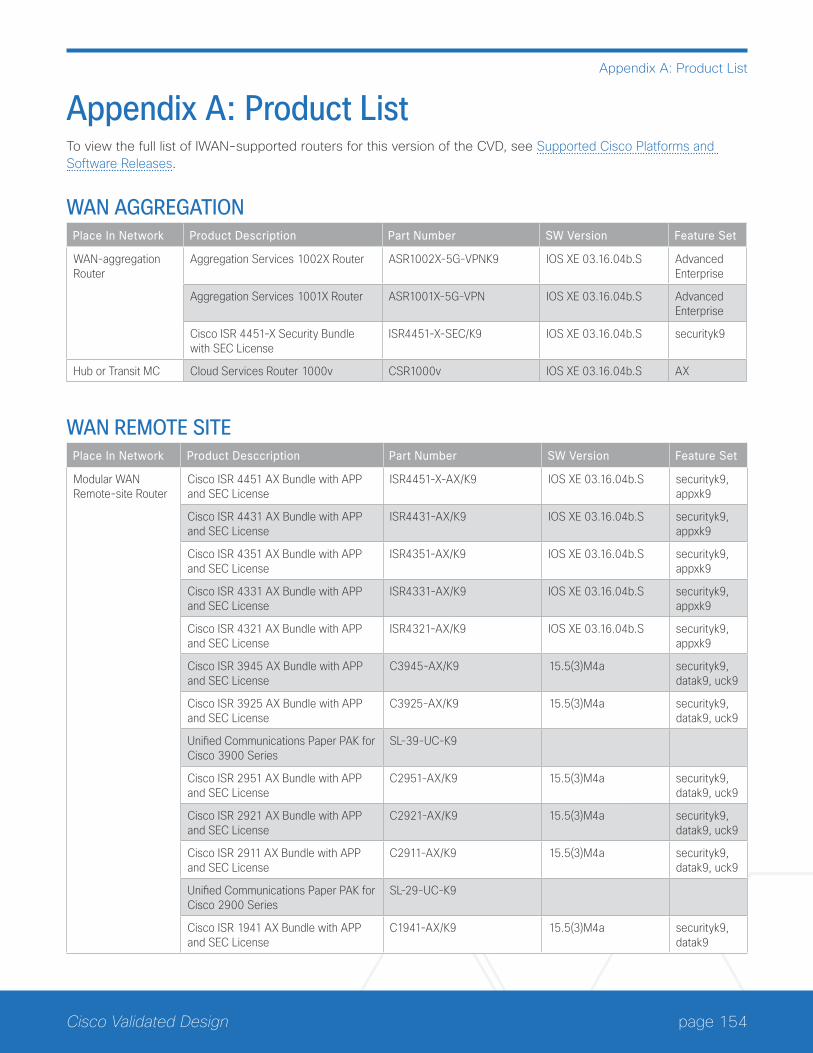
page 154Cisco Validated Design
Appendix A: Product List
Appendix A: Product ListTo view the full list of IWAN-supported routers for this version of the CVD, see Supported Cisco Platforms and Software Releases.
WAN AGGREGATIONPlace In Network Product Description Part Number SW Version Feature Set
WAN-aggregation Router
Aggregation Services 1002X Router ASR1002X-5G-VPNK9 IOS XE 03.16.04b.S Advanced Enterprise
Aggregation Services 1001X Router ASR1001X-5G-VPN IOS XE 03.16.04b.S Advanced Enterprise
Cisco ISR 4451-X Security Bundle with SEC License
ISR4451-X-SEC/K9 IOS XE 03.16.04b.S securityk9
Hub or Transit MC Cloud Services Router 1000v CSR1000v IOS XE 03.16.04b.S AX
WAN REMOTE SITEPlace In Network Product Desccription Part Number SW Version Feature Set
Modular WAN Remote-site Router
Cisco ISR 4451 AX Bundle with APP and SEC License
ISR4451-X-AX/K9 IOS XE 03.16.04b.S securityk9, appxk9
Cisco ISR 4431 AX Bundle with APP and SEC License
ISR4431-AX/K9 IOS XE 03.16.04b.S securityk9, appxk9
Cisco ISR 4351 AX Bundle with APP and SEC License
ISR4351-AX/K9 IOS XE 03.16.04b.S securityk9, appxk9
Cisco ISR 4331 AX Bundle with APP and SEC License
ISR4331-AX/K9 IOS XE 03.16.04b.S securityk9, appxk9
Cisco ISR 4321 AX Bundle with APP and SEC License
ISR4321-AX/K9 IOS XE 03.16.04b.S securityk9, appxk9
Cisco ISR 3945 AX Bundle with APP and SEC License
C3945-AX/K9 15.5(3)M4a securityk9, datak9, uck9
Cisco ISR 3925 AX Bundle with APP and SEC License
C3925-AX/K9 15.5(3)M4a securityk9, datak9, uck9
Unified Communications Paper PAK for Cisco 3900 Series
SL-39-UC-K9
Cisco ISR 2951 AX Bundle with APP and SEC License
C2951-AX/K9 15.5(3)M4a securityk9, datak9, uck9
Cisco ISR 2921 AX Bundle with APP and SEC License
C2921-AX/K9 15.5(3)M4a securityk9, datak9, uck9
Cisco ISR 2911 AX Bundle with APP and SEC License
C2911-AX/K9 15.5(3)M4a securityk9, datak9, uck9
Unified Communications Paper PAK for Cisco 2900 Series
SL-29-UC-K9
Cisco ISR 1941 AX Bundle with APP and SEC License
C1941-AX/K9 15.5(3)M4a securityk9, datak9
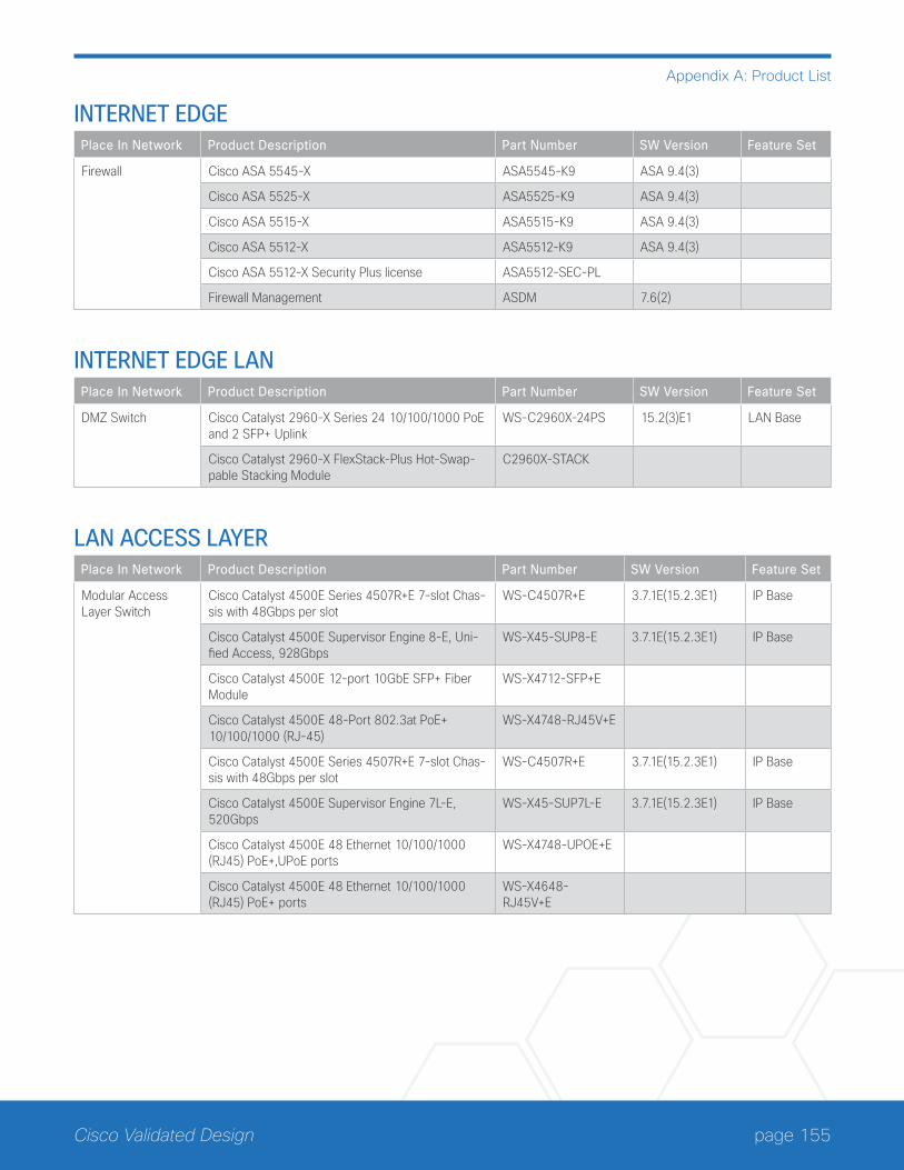
page 155Cisco Validated Design
Appendix A: Product List
INTERNET EDGEPlace In Network Product Description Part Number SW Version Feature Set
Firewall Cisco ASA 5545-X ASA5545-K9 ASA 9.4(3)
Cisco ASA 5525-X ASA5525-K9 ASA 9.4(3)
Cisco ASA 5515-X ASA5515-K9 ASA 9.4(3)
Cisco ASA 5512-X ASA5512-K9 ASA 9.4(3)
Cisco ASA 5512-X Security Plus license ASA5512-SEC-PL
Firewall Management ASDM 7.6(2)
INTERNET EDGE LANPlace In Network Product Description Part Number SW Version Feature Set
DMZ Switch Cisco Catalyst 2960-X Series 24 10/100/1000 PoE and 2 SFP+ Uplink
WS-C2960X-24PS 15.2(3)E1 LAN Base
Cisco Catalyst 2960-X FlexStack-Plus Hot-Swap-pable Stacking Module
C2960X-STACK
LAN ACCESS LAYERPlace In Network Product Description Part Number SW Version Feature Set
Modular Access Layer Switch
Cisco Catalyst 4500E Series 4507R+E 7-slot Chas-sis with 48Gbps per slot
WS-C4507R+E 3.7.1E(15.2.3E1) IP Base
Cisco Catalyst 4500E Supervisor Engine 8-E, Uni-fied Access, 928Gbps
WS-X45-SUP8-E 3.7.1E(15.2.3E1) IP Base
Cisco Catalyst 4500E 12-port 10GbE SFP+ Fiber Module
WS-X4712-SFP+E
Cisco Catalyst 4500E 48-Port 802.3at PoE+ 10/100/1000 (RJ-45)
WS-X4748-RJ45V+E
Cisco Catalyst 4500E Series 4507R+E 7-slot Chas-sis with 48Gbps per slot
WS-C4507R+E 3.7.1E(15.2.3E1) IP Base
Cisco Catalyst 4500E Supervisor Engine 7L-E, 520Gbps
WS-X45-SUP7L-E 3.7.1E(15.2.3E1) IP Base
Cisco Catalyst 4500E 48 Ethernet 10/100/1000 (RJ45) PoE+,UPoE ports
WS-X4748-UPOE+E
Cisco Catalyst 4500E 48 Ethernet 10/100/1000 (RJ45) PoE+ ports
WS-X4648-RJ45V+E

page 156Cisco Validated Design
Appendix A: Product List
Place In Network Product Description Part Number SW Version Feature Set
Stackable Access Layer Switch
Cisco Catalyst 3850 Series Stackable 48 Ethernet 10/100/1000 PoE+ ports
WS-C3850-48F 3.7.1E(15.2.3E1) IP Base
Cisco Catalyst 3850 Series Stackable 24 Ethernet 10/100/1000 PoE+ Ports
WS-C3850-24P 3.7.1E(15.2.3E1) IP Base
Cisco Catalyst 3850 Series 2 x 10GE Network Module
C3850-NM-2-10G
Cisco Catalyst 3850 Series 4 x 1GE Network Module
C3850-NM-4-1G
Cisco Catalyst 3650 Series 24 Ethernet 10/100/1000 PoE+ and 2x10GE or 4x1GE Uplink
WS-C3650-24PD 3.7.1E(15.2.3E1) IP Base
Cisco Catalyst 3650 Series 24 Ethernet 10/100/1000 PoE+ and 4x1GE Uplink
WS-C3650-24PS 3.7.1E(15.2.3E1) IP Base
Cisco Catalyst 3650 Series Stack Module C3650-STACK
Cisco Catalyst 2960-X Series 24 10/100/1000 Ethernet and 2 SFP+ Uplink
WS-C2960X-24PD 15.2(3)E1 LAN Base
Standalone Access Layer Switch
Cisco Catalyst 3650 Series 24 Ethernet 10/100/1000 PoE+ and 4x1GE Uplink
WS-C3650-24PS 3.7.1E(15.2.3E1) IP Base
LAN DISTRIBUTION LAYERPlace In Network Product Description Part Number SW Version Feature Set
Modular Distribution Layer Virtual Switch Pair
Cisco Catalyst 6500 VSS Supervisor 2T with 2 ports 10GbE and PFC4
VS-S2T-10G 15.2(1)SY1 IP Services
Cisco Catalyst 6800 Series 6807-XL 7-Slot Modu-lar Chassis
C6807-XL 15.2(1)SY1 IP Services
Cisco Catalyst 6500 4-port 40GbE/16-port 10GbE Fiber Module w/DFC4
WS-X6904-40G-2T
Cisco Catalyst 6500 4-port 10GbE SFP+ adapter for WX-X6904-40G module
CVR-CFP-4SFP10G
Cisco Catalyst 6500 CEF720 48 port 10/100/1000mb Ethernet
WS-X6748-GE-TX
Cisco Catalyst 6500 Distributed Forwarding Card 4 WS-F6K-DFC4-A
Cisco Catalyst 6500 Series 6506-E 6-Slot Chassis WS-C6506-E 15.2(1)SY1 IP services
Cisco Catalyst 6500 VSS Supervisor 2T with 2 ports 10GbE and PFC4
VS-S2T-10G 15.2(1)SY1 IP services
Cisco Catalyst 6500 4-port 40GbE/16-port 10GbE Fiber Module w/DFC4
WS-X6904-40G-2T
Cisco Catalyst 6500 4-port 10GbE SFP+ adapter for WX-X6904-40G module
CVR-CFP-4SFP10G
Cisco Catalyst 6500 48-port GigE Mod (SFP) WS-X6748-SFP
Cisco Catalyst 6500 Distributed Forwarding Card 4 WS-F6K-DFC4-A
Cisco Catalyst 6500 24-port GigE Mod (SFP) WS-X6724-SFP
Cisco Catalyst 6500 Distributed Forwarding Card 4 WS-F6K-DFC4-A
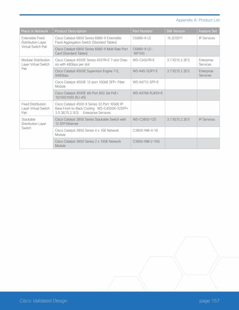
page 157Cisco Validated Design
Appendix A: Product List
Place in Network Product Description Part Number SW Version Feature Set
Extensible Fixed Distribution Layer Virtual Switch Pair
Cisco Catalyst 6800 Series 6880-X Extensible Fixed Aggregation Switch (Standard Tables)
C6880-X-LE 15.2(1)SY1 IP Services
Cisco Catalyst 6800 Series 6880-X Multi Rate Port Card (Standard Tables)
C6880-X-LE-16P10G
Modular Distribution Layer Virtual Switch Pair
Cisco Catalyst 4500E Series 4507R+E 7-slot Chas-sis with 48Gbps per slot
WS-C4507R+E 3.7.1E(15.2.3E1) Enterprise Services
Cisco Catalyst 4500E Supervisor Engine 7-E, 848Gbps
WS-X45-SUP7-E 3.7.1E(15.2.3E1) Enterprise Services
Cisco Catalyst 4500E 12-port 10GbE SFP+ Fiber Module
WS-X4712-SFP+E
Cisco Catalyst 4500E 48-Port 802.3at PoE+ 10/100/1000 (RJ-45)
WS-X4748-RJ45V+E
Fixed Distribution Layer Virtual Switch Pair
Cisco Catalyst 4500-X Series 32 Port 10GbE IP Base Front-to-Back Cooling WS-C4500X-32SFP+ 3.5.3E(15.2.1E3) Enterprise Services
Stackable Distribution Layer Switch
Cisco Catalyst 3850 Series Stackable Switch with 12 SFP Ethernet
WS-C3850-12S 3.7.1E(15.2.3E1) IP Services
Cisco Catalyst 3850 Series 4 x 1GE Network Module
C3850-NM-4-1G
Cisco Catalyst 3850 Series 2 x 10GE Network Module
C3850-NM-2-10G
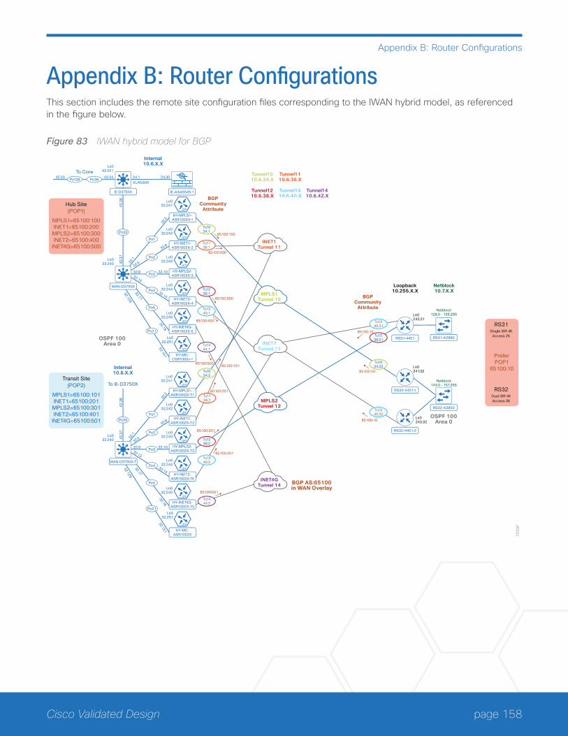
page 158Cisco Validated Design
Appendix B: Router Configurations
Appendix B: Router ConfigurationsThis section includes the remote site configuration files corresponding to the IWAN hybrid model, as referenced in the figure below.
Figure 83 IWAN hybrid model for BGP
32.17
32.18
70
39
F
WAN-D3750X
32.9 32.10
IE-D3750X
HY-MPLS1-ASR1002X-1
Po13642.33
To Core
Po3642.34 24.1 24.30
32.2
32.1
32.5
32.6
To IE-D3750X
Po2
Po332.13
32.14
Po4
Po5
32.129
32.151
Po21
Po1
Tu1034.1
Tu1238.1
Tu1340.1
VLAN300
Po33
42
.38
42
.37
Lo042.251
Lo032.241
65100:100
HY-INET1-ASR1002X-2
Lo032.242
HY-MPLS2-ASR1002X-3
Lo032.243
HY-INET2-ASR1002X-4
Lo032.244
HY-INET4G-ASR1002X-5
Lo032.245
HY-MC-CSR1000v-1
Lo032.251
Lo032.240
Lo032.240
Internal10.6.X.X
Tunnel1010.6.34.X
Tunnel1210.6.38.X
Tunnel1110.6.36.X
Tunnel1310.6.40.X
Tunnel1410.6.42.X
Loopback10.255.X.X
Netblock10.7.X.X
BGPCommunity
Attribute
BGP AS:65100in WAN Overlay
OSPF 100Area 0
OSPF 100Area 0
BGPCommunity
Attribute
Internal10.8.X.X
Hub Site(POP1)
MPLS1=65100:100INET1=65100:200
MPLS2=65100:300INET2=65100:400
INET4G=65100:500
Transit Site(POP2)
MPLS1=65100:101INET1=65100:201
MPLS2=65100:301INET2=65100:401
INET4G=65100:501
32.17
32.18
WAN-D3750X-T
32.9 32.10
HY-MPLS1-ASR1002X-T1
32.2
32.1
32.5
32.6
Po2
Po332.13
32.14
Po4
Po5
32.129
32.151
Po21
Po1
Tu1136.2
Tu1034.2
Tu1238.2
Tu1340.2
Tu1444.2
Po35
42
.38
42
.37
Lo032.241
HY-INET1-ASR1002X-T2
Lo032.242
HY-MPLS2-ASR1002X-T3
Lo032.243
HY-INET2-ASR1002X-T4
Lo032.244
HY-INET4G-ASR1002X-T5
Lo032.245
HY-MC-ASR1002X
Lo032.251
IE-ASA5545-1
INET1Tunnel 11
MPLS1Tunnel 10
INET2Tunnel 13
MPLS2Tunnel 12
INET4GTunnel 14
PreferPOP1
65100:10
RS31Single ISR 4K
Access 2K
RS32Dual ISR 4KAccess 3K
Tu1034.32
RS31-4451 RS31-A2960
Lo0243.31
RS32-4451-1
RS32-A3850
Lo0241.32
Netblock144.0 - 151.255
Netblock128.0 - 135.255
RS32-4451-2
Lo0243.32
Tu1238.31
Tu1340.31
Tu1340.32
Tu1136.1
Tu1444.1
65100:10
65100:10
65100:10
65100:300
65100:400
65100:50065100:101
65100:201
65100:301
65100:401
65100:501
65100:200
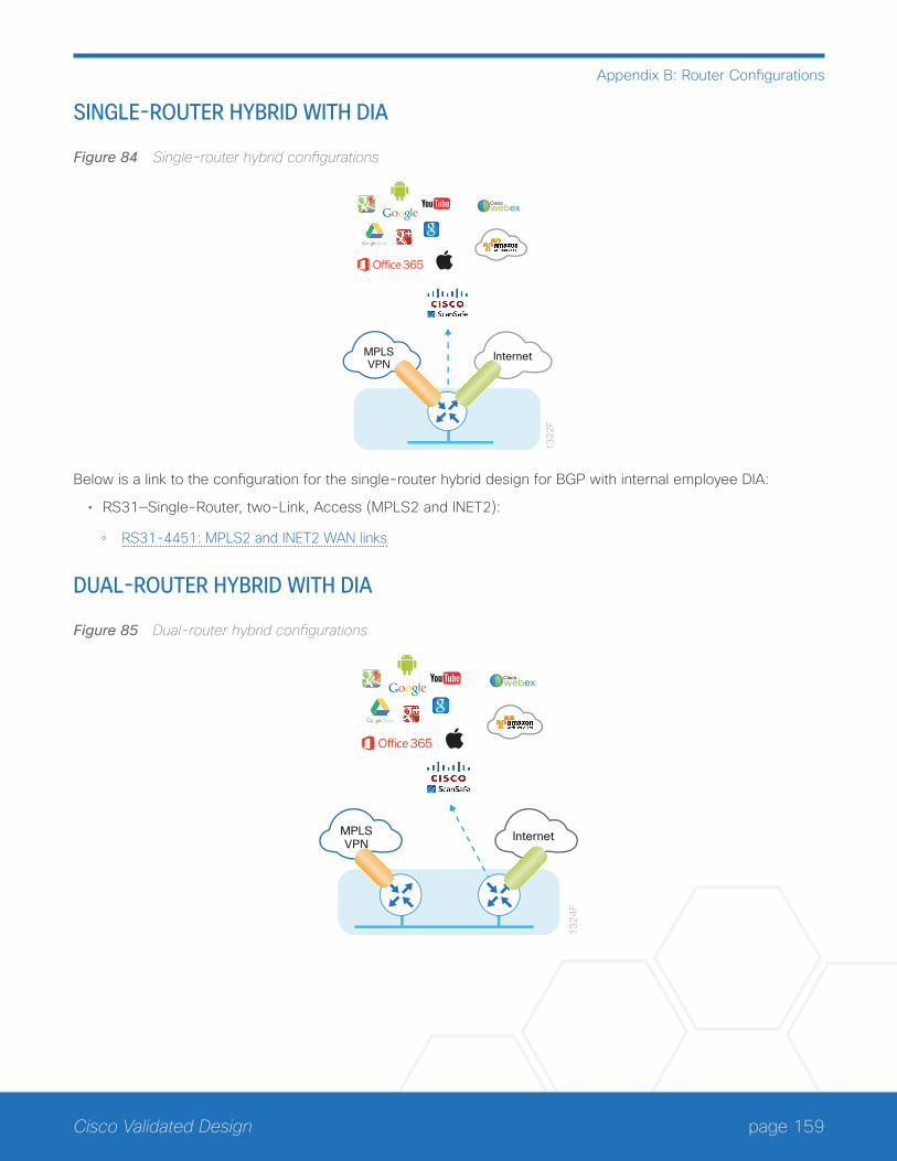
page 159Cisco Validated Design
Appendix B: Router Configurations
SINGLE-ROUTER HYBRID WITH DIA
Figure 84 Single-router hybrid configurations
MPLSVPN
Internet
13
22
F
Ciscowebex
Below is a link to the configuration for the single-router hybrid design for BGP with internal employee DIA:
• RS31—Single-Router, two-Link, Access (MPLS2 and INET2):
◦ RS31-4451: MPLS2 and INET2 WAN links
DUAL-ROUTER HYBRID WITH DIA
Figure 85 Dual-router hybrid configurations
13
24
F
InternetMPLSVPN
Ciscowebex
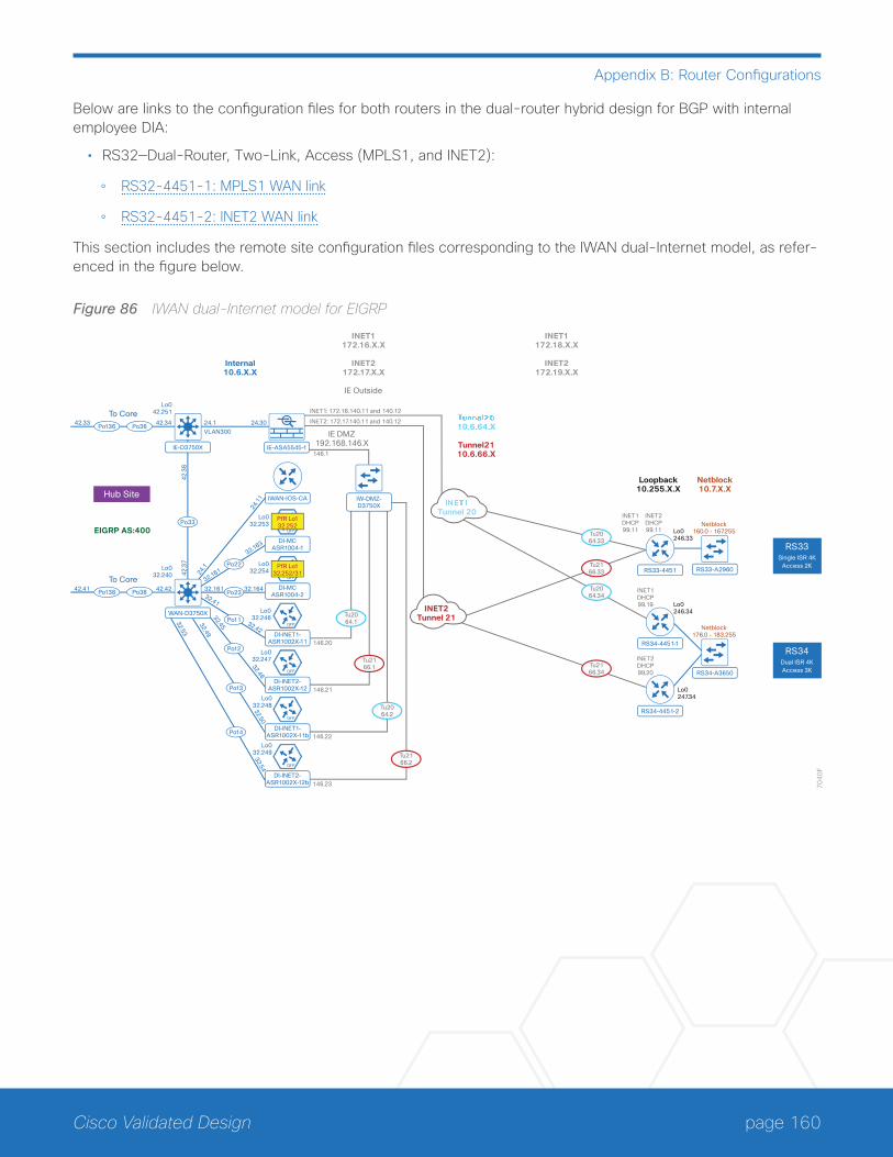
page 160Cisco Validated Design
Appendix B: Router Configurations
Below are links to the configuration files for both routers in the dual-router hybrid design for BGP with internal employee DIA:
• RS32—Dual-Router, Two-Link, Access (MPLS1, and INET2):
◦ RS32-4451-1: MPLS1 WAN link
◦ RS32-4451-2: INET2 WAN link
This section includes the remote site configuration files corresponding to the IWAN dual-Internet model, as refer-enced in the figure below.
Figure 86 IWAN dual-Internet model for EIGRP
32.45
32.46
70
40
F
WAN-D3750X
Po13842.41To Core
Po38 42.42 32.161 32.164
IE-D3750X
IW-DMZ-D3750X
Po13642.33
To Core
Po3642.34 24.1 24.30
24.1
1
24.1
32.161
32.163
Po22
Po2332.41
32.42
Po11
Po12
32.49
32.50
Po13
Tu2166.1
Tu2064.1
Tu2064.33
Tu2166.34
Tu2166.33
INET1: 172.16.140.11 and 140.12
INET2: 172.17.140.11 and 140.12
146.1
146.20
Tu2064.2
146.22
146.23
146.21
VLAN300
Po33
42
.38
42
.37
Lo042.251
DI-MCASR1004-1
Lo032.253
DI-MCASR1004-2
Lo032.254
DI-INET1-ASR1002X-11
Lo032.246
DI-INET2-ASR1002X-12
Lo032.247
DI-INET1-ASR1002X-11b
Lo032.248
32.53
32.54
Po14
DI-INET2-ASR1002X-12b
Lo032.249
Lo032.240
Internal10.6.X.X
INET1172.16.X.X
INET2172.17.X.X
IE Outside
INET1172.18.X.X
INET2172.19.X.X
10.6.64.X
Tunnel2110.6.66.X
EIGRP AS:400
Loopback10.255.X.X
Netblock10.7.X.X
Hub Site
IE-ASA5545-1
Tunnel 20
INET2Tunnel 21
IWAN-IOS-CA
INET1DHCP99.19
INET2DHCP99.20
INET1DHCP99.11
INET2DHCP99.11
RS33-4451 RS33-A2960
Lo0246.33
Netblock160.0 - 167.255
RS33Single ISR 4K
Access 2K
RS34-4451-1
RS34-A3650
Lo0246.34
Netblock176.0 - 183.255
RS34Dual ISR 4KAccess 3K
RS34-4451-2
Lo0247.34
IE DMZ192.168.146.X
Tu2166.2
PfR Lo132.252
PfR Lo132.252/31
Tu2064.34
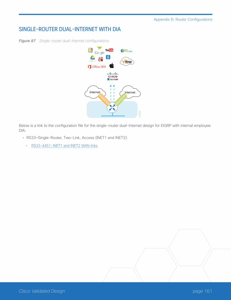
page 161Cisco Validated Design
Appendix B: Router Configurations
SINGLE-ROUTER DUAL-INTERNET WITH DIA
Figure 87 Single-router dual-Internet configurations
13
25
F
Internet Internet
Ciscowebex
Below is a link to the configuration file for the single-router dual-Internet design for EIGRP with internal employee DIA:
• RS33—Single-Router, Two-Link, Access (INET1 and INET2):
◦ RS33-4451: INET1 and INET2 WAN links

page 162Cisco Validated Design
Appendix B: Router Configurations
DUAL-ROUTER DUAL-INTERNET WITH DIA
Figure 88 Dual-router dual-Internet configurations
13
27
F
Internet Internet
Ciscowebex
Below are links to the configuration files for both routers in the dual-router dual-Internet design for EIGRP with internal employee DIA:
• RS34—Dual-Router, Two-Link, Access (INET1 and INET2):
◦ RS34-4451-1: INET1 WAN link
◦ RS34-4451-2: INET2 WAN link
page 163Cisco Validated Design
Appendix C: DIA with PfR Load-Balancing
Appendix C: DIA with PfR Load-BalancingOptionalFollow the optional steps in this appendix if your hybrid DIA environment requires PfR load-balancing. The DIA configuration must be completed as specified in the hybrid sections of this guide when implementing the changes listed below.
Configuring DIA with PfR Load-Balancing
1. Configure static IP address, default route and NAT
2. Configure IP next hop tracking
3. Configure policy-based routingPR
OC
ESS
This solution requires policy based routing and a static IP address on the Internet-facing WAN interface.
Procedure 1 Configure static IP address, default route and NAT
Step 1: Configure a static IP address on the Internet-facing WAN interface.
This feature requires a static IP address from your service provider.
interface GigabitEthernet0/0/1
ip address 172.19.98.43 255.255.255.248
Step 2: Configure a static default route for the Internet-facing WAN interface.
With a static IP address, you need a static default route in the Internet VRF.
ip route vrf IWAN-TRANSPORT-4 0.0.0.0 0.0.0.0 172.19.98.41
Step 3: Configure NAT for the Internet-facing WAN interface.
The NAT statement needs to specify the Internet VRF.
ip nat inside source route-map NAT interface GigabitEthernet0/0/1 vrf IWAN-TRANSPORT-4 overload
Procedure 2 Configure IP next hop tracking
Step 1: Configure the VRF-aware IPSLA ICMP probe.
Create the ip sla probe using the service providers next-hop gateway IP address and the source interface of the
page 164Cisco Validated Design
Appendix C: DIA with PfR Load-Balancing
Internet-facing WAN. Specify the F-VRF for the interface, schedule the sla to start now and run forever.
ip sla 13
icmp-echo 172.19.98.41 source-interface GigabitEthernet0/0/1
vrf IWAN-TRANSPORT-4
threshold 500
frequency 10
ip sla schedule 13 life forever start-time now
Step 2: Configure the tracking parameters and logic for the IPSLA ICMP probes..
track 13 ip sla 13 reachability
Procedure 3 Configure policy-based routing
Step 1: Configure the access list for local LAN to DIA traffic.
Deny traffic to the IP address range defined in your enterprise prefix statement and permit all other traffic des-tined for the Internet.
ip access-list extended LAN-TO-DIA
deny ip any 10.4.0.0 0.3.255.255 log
permit ip any any log
Step 2: Configure the route map for LAN to DIA traffic.
Match the traffic using the access list from the previous step. Set the next-hop IP address in the Internet VRF. Verify the next hop IP address is available by using the IPSLA track from the previous procedure.
route-map TRAFFIC-TO-PROXY-AND-DIA permit 10
description Internal PBR-DIA-Fallback
match ip address LAN-TO-DIA
set ip vrf IWAN-TRANSPORT-4 next-hop verify-availability 172.19.98.41 1 track 13
Step 3: Apply the route map to the LAN interface.
Apply the route map from the previous step to the LAN-facing interface.
interface GigabitEthernet0/0/2.64
ip policy route-map TRAFFIC-TO-PROXY-AND-DIA
The return traffic will follow the same path as the DIA configurations discussed elsewhere in the guide.

page 165Cisco Validated Design
Appendix C: DIA with PfR Load-Balancing
Single-Router Hybrid with DIA and PfR Load-balancingBelow is a link to the configuration file for the single-router hybrid design for BGP with internal employee DIA and PfR load-balancing:
• RS31—Single-Router, two-Link, Access (MPLS2 and INET2):
◦ RS31-4451: MPLS2 and INET2 WAN links
page 166Cisco Validated Design
Appendix D: Changes
Appendix D: ChangesThis appendix summarizes the changes Cisco made to this guide since its last edition:
• Routing Updates
◦ Added iBGP in WAN overlay with OSPF on LAN as an option
• PfR Updates
◦ Added a PfR load-balancing example as an optional configuration

Americas HeadquartersCisco Systems, Inc.San Jose, CA
Asia Pacific HeadquartersCisco Systems (USA) Pte. Ltd.Singapore
Europe HeadquartersCisco Systems International BV Amsterdam,The Netherlands
Cisco has more than 200 offices worldwide. Addresses, phone numbers, and fax numbers are listed on the Cisco Website at www.cisco.com/go/offices.
ALL DESIGNS, SPECIFICATIONS, STATEMENTS, INFORMATION, AND RECOMMENDATIONS (COLLECTIVELY, “DESIGNS”) IN THIS MANUAL ARE PRESENTED “AS IS,” WITH ALL FAULTS. CISCO AND ITS SUPPLIERS DISCLAIM ALL WARRANTIES, INCLUDING, WITHOUT LIMITATION, THE WARRANTY OF MERCHANTABILITY, FITNESS FOR A PARTICULAR PURPOSE AND NONINFRINGEMENT OR ARISING FROM A COURSE OF DEALING, USAGE, OR TRADE PRACTICE. IN NO EVENT SHALL CISCO OR ITS SUPPLIERS BE LIABLE FOR ANY INDIRECT, SPECIAL, CONSEQUENTIAL, OR INCIDENTAL DAMAGES, INCLUDING, WITHOUT LIMITATION, LOST PROFITS OR LOSS OR DAMAGE TO DATA ARISING OUT OF THE USE OR INABILITY TO USE THE DESIGNS, EVEN IF CISCO OR ITS SUPPLIERS HAVE BEEN ADVISED OF THE POSSIBILITY OF SUCH DAMAGES. THE DESIGNS ARE SUBJECT TO CHANGE WITHOUT NOTICE. USERS ARE SOLELY RESPONSIBLE FOR THEIR APPLICATION OF THE DESIGNS. THE DESIGNS DO NOT CONSTITUTE THE TECHNICAL OR OTHER PROFESSIONAL ADVICE OF CISCO, ITS SUPPLIERS OR PARTNERS. USERS SHOULD CONSULT THEIR OWN TECHNICAL ADVISORS BEFORE IMPLEMENTING THE DESIGNS. RESULTS MAY VARY DEPENDING ON FACTORS NOT TESTED BY CISCO.
Any Internet Protocol (IP) addresses used in this document are not intended to be actual addresses. Any examples, command display output, and figures included in the document are shown for illustrative purposes only. Any use of actual IP addresses in illustrative content is unintentional and coincidental.
© 2016 Cisco Systems, Inc. All rights reserved.
Cisco and the Cisco logo are trademarks or registered trademarks of Cisco and/or its affiliates in the U.S. and other countries. To view a list of Cisco trademarks, go to this URL: www.cisco.com/go/trademarks. Third-party trademarks mentioned are the property of their respective owners. The use of the word partner does not imply a partnership relationship between Cisco and any other company. (1110R)
Cisco Validated Design
Please use the feedback form to send comments and suggestions about this guide.
B-000220i-2 03/17


