
JAPAN INTERNATIONAL COOPERATION AGENCY (JICA)
VIETNAM RAILWAYS (VR)
STUDY FOR THE FORMULATION OF HIGH SPEED RAILWAY
PROJECTS ON HANOI – VINH AND HO CHI MINH – NHA TRANG
SECTION
FINAL REPORT
TECHNICAL REPORT 1
ASSESSMENT OF EXISTING RAILWAY AND IMPROVEMENT
OPTIONS
June 2013
ALMEC CORPORATION
JAPAN INTERNATIONAL CONSULTANTS FOR TRANSPORTATION CO., LTD.
ORIENTAL CONSULTANTS CO., LTD.
NIPPON KOEI CO., LTD.
JAPAN TRANSPORTATION CONSULTANTS, INC. E I
J R
1 3 - 1 7 8

Exchange rate used in the Report
USD 1 = JPY 78 = VND 21,000
(Based on rate on November 2011)
PREFACE
In response to the request from the Government of the Socialist Republic of Vietnam, the
Government of Japan decided to conduct the Study for the Formulation of High Speed Railway
Projects on Hanoi – Vinh and Ho Chi Minh – Nha Trang Section and entrusted the program to
the Japan International cooperation Agency (JICA).
JICA dispatched a team to Vietnam between April 2011 and June 2013, which was headed
by Mr. IWATA Shizuo of ALMEC Corporation and consisted of ALMEC Corporation, Japan
International Consultants for Transportation Co., Ltd., Oriental Consultants Co., Ltd., Nippon
Koei Co., Ltd. and Japan Transportation Consultants, Inc.
In the cooperation with the Vietnamese Counterpart Team including the Ministry of
Transport and Vietnam Railways, the JICA Study Team conducted the study which includes
traffic demand analysis, natural and socio-economic conditions, alignment planning,
consideration of various options including the upgrading of existing railway, technical
standards for high speed railway, implementation schedule and institutions, and human
resource development. It also held a series of discussions with the relevant officials of the
Government of Vietnam. Upon returning to Japan, the Team duly finalized the study and
delivered this report in June 2013.
Reflecting on the history of railway development in Japan, it is noted that Japan has indeed
a great deal of experience in the planning, construction, operation, etc., and it is deemed that
such experiences will greatly contribute to the railway development in Vietnam. JICA is
willing to provide further cooperation to Vietnam to achieve sustainable development of railway
sector and to enhance friendly relationship between the two countries.
It is hoped that this report will contribute to the sustainable development of transport
system in Vietnam and to the enhancement of friendly relations between the two countries.
Finally, I wish to express my sincere appreciation to the officials of the Government of
Vietnam for their close cooperation.
June 2013
Kazuki Miura
Director, Economic Infrastructure Department
Japan International Cooperation Agency
i
TABLE OF CONTENTS
1 CONSTRAINTS AND OPPORTUNITIES OF THE EXISTING NORTH-SOUTH
RAILWAY LINE
1.1 Existing Conditions of the North-South Railway ................................................................. 1-1
1.2 Main Bottlenecks in Existing Railway ................................................................................. 1-7
1.3 Opportunities and Constrains to Improvement of Existing Line ........................................ 1-14
1.4 Alternative Improvement Options for the North-South Railway Line ................................. 1-21
2 OPERATION CONTROL
2.1 Operation Control ............................................................................................................... 2-1
2.2 Phased Development of Operation Control ........................................................................ 2-1
2.3 Present Status of the Operation Control of Vietnam Railways ........................................... 2-3
2.4 Operation Control Recommended for the Improved Options of Existing Lines ................... 2-3
3 TRAIN OPERATION
3.1 Option A-1 .......................................................................................................................... 3-1
3.2 Option A-2 .......................................................................................................................... 3-3
3.3 Option B-1 .......................................................................................................................... 3-6
3.4 Option B-2 ........................................................................................................................ 3-10
4 INFRASTRUCTURE AND STATION
4.1 Option A-1 .......................................................................................................................... 4-1
4.2 Option A-2 ........................................................................................................................ 4-13
4.3 Option B-1 ........................................................................................................................ 4-31
4.4 Option B-2 ........................................................................................................................ 4-44
5 TRACK
5.1 Option A-1 .......................................................................................................................... 5-1
5.2 Option A-2 .......................................................................................................................... 5-2
5.3 Option B-1 .......................................................................................................................... 5-3
5.4 Option B2 ........................................................................................................................... 5-5
6 POWER SUPPLY SYSTEM
6.1 General ............................................................................................................................. 6-1
6.2 Substations and Related Facilities ...................................................................................... 6-3
6.3 Monitor and Control System ............................................................................................... 6-3
6.4 Principal Work to be undertaken by the Civil Engineering Side .......................................... 6-3
ii
6.5 Principal Work to be undertaken by the Architecture Side .................................................. 6-4
6.6 Contact Wire Equipment ..................................................................................................... 6-4
6.7 Facilities for Lighting and Power ......................................................................................... 6-6
7 SIGNALING AND TELECOMMUNICATION
7.1 Option A-1 .......................................................................................................................... 7-1
7.2 Option A-2 .......................................................................................................................... 7-5
7.3 Option B-1 .......................................................................................................................... 7-7
7.4 Option B-2 .......................................................................................................................... 7-9
8 ROLLING STOCK
8.1 Option A-1 .......................................................................................................................... 8-1
8.2 Option A-2 .......................................................................................................................... 8-1
8.3 Option B-1 .......................................................................................................................... 8-3
8.4 Option B-2 .......................................................................................................................... 8-5
9 DEPOT AND WORKSHOP
9.1 Option A-2 .......................................................................................................................... 9-1
9.2 Option B-1 .......................................................................................................................... 9-2
9.3 Option B-2 .......................................................................................................................... 9-4
10 INVESTMENT COST OF EXISTING IMPROVEMENT OPTIONS
10.1 Investment Cost of 3 Options ............................................................................. 10-1
10.2 Investment Cost of 7 Sections of Options A2, B1 and B2 ................................... 10-6
iii
LIST OF TABLES Table 1.1.1 Profile of Existing Line ................................................................................................ 1-2
Table 1.2.1 Identified Main Problems of Existing Railways ........................................................... 1-7
Table 1.2.2 Distance between Stations and Characteristics of Curvature ................................... 1-13
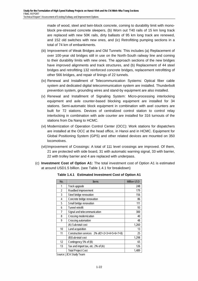
Table 1.4.1 Estimated Investment Cost of Option A1 .................................................................. 1-22
Table 1.4.2 Estimated Investment Cost of Option A2 .................................................................. 1-24
Table 1.4.3 Estimated Investment Cost of Option B1 .................................................................. 1-25
Table 1.4.4 Estimated Investment Cost of Option B2 .................................................................. 1-27
Table 1.4.5 Summary of Four Options (A1, A2, B1 and B2) ........................................................ 1-28
Table 1.4.6 Investment Cost of Improvement Plans of Existing Railway .................................... 1-29
Table 3.1.1 Train Speed ................................................................................................................. 3-2
Table 3.1.2 Line Capacity .............................................................................................................. 3-2
Table 3.2.1 New Stations ............................................................................................................... 3-3
Table 3.2.2 Effect of Tunneling ...................................................................................................... 3-4
Table 3.3.1 Prerequisite Conditions for the Option B-1 ................................................................. 3-6
Table 3.3.2 Operation Time of B-1 ................................................................................................. 3-7
Table 3.4.1 Prerequisite Conditions for the Option B-2 ............................................................... 3-10
Table 3.4.2 Operation Time of Passenger Trains of B-2 .............................................................. 3-11
Table 3.4.3 Operation Time of Passenger Trains of B-2 .............................................................. 3-12
Table 4.1.1 List of 22 Tunnels in Line ............................................................................................ 4-6
Table 4.1.2 Structural Length Applied to the Examination of A1 and A2 Plan ............................. 4-10
Table 4.1.3 Samples of Types of Foundation Structure in Line ................................................... 4-11
Table 4.2.1 Track Capacity of Sections ....................................................................................... 4-17
Table 4.2.2 Outline of Time Saving by A1 and A2 ....................................................................... 4-17
Table 4.2.3 Summary of Sections of 18 New Pass-by Stations ................................................... 4-19
Table 4.2.4 Scheme of Three Projects......................................................................................... 4-26
Table 4.3.1 Design Standard ........................................................................................................ 4-31
Table 4.3.2 Bridge Span Length and Structural Plan ................................................................... 4-32
Table 4.3.3 Old and New Tunnel Section .................................................................................... 4-36
Table 4.3.4 Add Up Sections ....................................................................................................... 4-42
Table 4.3.5 Summary of Quantity ................................................................................................ 4-43
Table 4.4.1 Design Standard ........................................................................................................ 4-44
Table 4.4.2 Bridge Span Length and Structural Plan ................................................................... 4-45
Table 4.4.3 Station Form and Application .................................................................................... 4-49
Table 4.4.4 Classification of Current Line .................................................................................... 4-52
Table 4.4.5 Add Up Sections ....................................................................................................... 4-52
Table 4.4.6 Length and Area of the Station .................................................................................. 4-53
Table 4.4.7 Summary of Quantity ................................................................................................ 4-54
Table 5.1.1 Project List of A-1 for Track Work ............................................................................... 5-1
Table 5.2.1 Project List of Option A-2 for Track Work .................................................................... 5-2
Table 6.1.1 Contact Wire Voltage .................................................................................................. 6-2
Table 6.2.1 Feeding Transformer ................................................................................................... 6-3
Table 6.6.1 Contact Wire Equipment ............................................................................................. 6-4
Table 6.6.2 Feeding Line ............................................................................................................... 6-4
Table 7.2.1 Level crossings in Provinces ....................................................................................... 7-6
Table 8.2.1 Number of Locomotives .............................................................................................. 8-2
Table 8.2.2 Number of Passenger Trainsets ................................................................................. 8-2
Table 8.2.3 Freight Trainsets ......................................................................................................... 8-2
iv
Table 8.2.4 Required Rolling Stocks Including on-standby and On-Maintenance ......................... 8-2
Table 8.3.1 Locomotives for Passenger Trains.............................................................................. 8-4
Table 8.3.2 Locomotives for Freight Trains .................................................................................... 8-4
Table 8.3.3 Passenger Trainsets ................................................................................................... 8-4
Table 8.3.4 Freight Trainsets ......................................................................................................... 8-4
Table 8.3.5 Required Rolling Stocks including On-standby and On-maintenance ........................ 8-4
Table 8.4.1 EMU for Express Train ................................................................................................ 8-5
Table 8.4.2 EMU for Local Train .................................................................................................... 8-5
Table 8.4.3 EMU Trainsets for Express Trains .............................................................................. 8-6
Table 8.4.4 EMU Trainsets for Local Trains ................................................................................... 8-7
Table 8.4.5 Locomotives for Freight Trains .................................................................................... 8-7
Table 8.4.6 Freight Trainsets ......................................................................................................... 8-7
Table 8.4.7 Required Rolling Stocks including On-standby and On-maintenance ........................ 8-7
Table 9.1.1 Location of Depot and Workshop for A-2 .................................................................... 9-1
Table 9.2.1 Location of Depot and Workshop for B-1 .................................................................... 9-2
Table 9.3.1 Location of Depot and Workshop for B-2 .................................................................... 9-4
Table 10.1.1 Estimated Investment Cost of Alternative A2 ............................................................ 10-1
Table 10.1.2 Cost Breakdown of Alternative A2............................................................................. 10-1
Table 10.1.3 Estimated Investment Cost of Alternative B1 ............................................................ 10-2
Table 10.1.4 Cost Breakdown of Alternative B1 ............................................................................ 10-2
Table 10.1.5 Estimated Investment Cost of Alternative B2 ............................................................ 10-3
Table 10.1.6 Cost Breakdown of Alternative B2 ............................................................................ 10-4
Table 10.2.1 Investment Cost of 7 Sections of Options A2, B1 and B2 ........................................ 10-6
LIST OF FIGURES Figure 1.1.1 Examples of Current Situation of Existing Railway ..................................................... 1-6
Figure 1.2.1 Locations of Bottlenecks ............................................................................................. 1-8
Figure 1.2.2 Realignment Plan of Hai Van Pass ............................................................................. 1-9
Figure 1.2.3 Realignment Plan of Hai Van Pass ........................................................................... 1-10
Figure 1.2.4 Realignment Plan of Khe Net Pass........................................................................... 1-11
Figure 1.2.5 Hoa Duyet–Thanh Luyen Section Upgrade Project .................................................. 1-12
Figure 1.2.6 Switchback Sections in Danang and Nha Trang ....................................................... 1-13
Figure 1.3.1 Dual Gauge (Photo) .................................................................................................. 1-15
Figure 1.3.2 Japanese Experiences of Gauge Conversion .......................................................... 1-15
Figure 1.3.3 Track Layout of Dual Gauge ..................................................................................... 1-16
Figure 1.3.4 Passenger and Freight Train Operation Diagram ..................................................... 1-20
Figure 3.1.1 Number of Trains for A-1 ............................................................................................. 3-1
Figure 3.2.1 A-2 Train Operation Diagram ...................................................................................... 3-4
Figure 3.2.2 Number of Trains for Option A-2 ................................................................................. 3-5
Figure 3.3.1 Volume of Passenger Transport: Series 1 .................................................................. 3-6
Figure 3.3.2 Volume of Freight Transport: Series 1 ........................................................................ 3-6
Figure 3.3.3 B-1 Train Operation Diagram ...................................................................................... 3-8
Figure 3.3.4 Number of Trains for Option B-1 ................................................................................. 3-9
Figure 3.4.1 “Hakutaka” type EMU ................................................................................................ 3-10
Figure 3.4.2 EF81 Type Electric Locomotive ................................................................................ 3-11
Figure 3.4.3 B-2 Train Operation Diagram .................................................................................... 3-13
Figure 3.4.4 Number of Trains for Option B-2 ............................................................................... 3-14
v
Figure 3.4.5 Basic Idea of Operation Diagram of Freight Trains 80 km/h ..................................... 3-14
Figure 4.2.1 Layout of Station (My Ly – Quan Hanh) .................................................................... 4-19
Figure 4.2.2 Layout of Station (Dong Le – Ngoc Lam) .................................................................. 4-20
Figure 4.2.3 Layout of Station (Thuong Lam – Sa Lung) .............................................................. 4-20
Figure 4.2.4 Layout of Station (Huong Thuy – Truoi) .................................................................... 4-20
Figure 4.2.5 Layout of Station (Tra Kieu – Phu Cang) .................................................................. 4-21
Figure 4.2.6 Layout of Station (Bong Son – Van Phu) .................................................................. 4-21
Figure 4.2.7 Layout of Station (Van Phu – Phu My) ...................................................................... 4-21
Figure 4.2.8 Layout of Station (Van Canh – Phuoc Lanh) ............................................................. 4-22
Figure 4.2.9 Layout of Station (La Hai – Chi Thanh) ..................................................................... 4-22
Figure 4.2.10 Layout of Station (Nha Trang – Cay Cay) ................................................................. 4-22
Figure 4.2.11 Layout of Station (Nga Ba – Ca Rom)....................................................................... 4-23
Figure 4.2.12 Layout of Station (Ca Na – Vinh Hao) ....................................................................... 4-23
Figure 4.2.13 Layout of Station (Long Song – Song Mao) .............................................................. 4-23
Figure 4.2.14 Layout of Station (Ma Lam – Muong Man) ................................................................ 4-24
Figure 4.2.15 Layout of Station (Muong Man – Suoi Van) .............................................................. 4-24
Figure 4.2.16 Layout of Station (Suoi Van – Song Phan) ................................................................ 4-24
Figure 4.2.17 Layout of Station (Long Khanh – Dau Giay) ............................................................. 4-25
Figure 4.2.18 Layout of Station (Dau Giay – Trang Bom) ............................................................... 4-25
Figure 4.2.19 Layout of Station (Gia Huynh – Tran Tao) ................................................................. 4-25
Figure 4.2.20 Layout of Station (Bao Chanh – Long Khanh) .......................................................... 4-26
Figure 4.2.21 Layout of Station (Trang Bom – Ho Nai) ................................................................... 4-26
Figure 4.2.22 Realignment Plan of Khe Net Pass (1/2) .................................................................. 4-27
Figure 4.2.23 Realignment Plan of Khe Net Pass (2/2) .................................................................. 4-28
Figure 4.2.24 Realignment Plan of Hai Van Pass ........................................................................... 4-29
Figure 4.2.25 Hoa Duyet–Thanh Luyen Section Upgrade Project .................................................. 4-30
Figure 4.3.1 Realignment Plan at Hai Van Pass ........................................................................... 4-32
Figure 4.3.2 Embankment & Cutting Section Drawings ................................................................ 4-33
Figure 4.3.3 RC Girder, T-Beam .................................................................................................... 4-34
Figure 4.3.4 Through Steel Plate Girder ....................................................................................... 4-34
Figure 4.3.5 Pony Steel Truss Girder ............................................................................................ 4-34
Figure 4.3.6 Trough Steel Truss Girder ......................................................................................... 4-35
Figure 4.3.7 Single Track Tunnel Section ..................................................................................... 4-37
Figure 4.3.8 Double Track Tunnel Section .................................................................................... 4-37
Figure 4.3.9 Station Layout Plan between Ha Noi and Sai Gon ................................................... 4-38
Figure 4.3.10 Station Model by Sections ......................................................................................... 4-39
Figure 4.3.11 Hanoi–Thanh Hoa Section ........................................................................................ 4-39
Figure 4.3.12 Thanh Hoa–Vinh Section .......................................................................................... 4-39
Figure 4.3.13 Vinh–Hue Section ..................................................................................................... 4-40
Figure 4.3.14 Hue–Da Nang Section .............................................................................................. 4-40
Figure 4.3.15 Da Nang–Nha Trang Section .................................................................................... 4-41
Figure 4.3.16 Nha Trang–Muong Man Section ............................................................................... 4-41
Figure 4.3.17 Muong Man–Sai Gon Section ................................................................................... 4-42
Figure 4.4.1 Approach Section to the Bridge ................................................................................ 4-45
Figure 4.4.2 New Embankment ..................................................................................................... 4-46
Figure 4.4.3 Widening of Embankment ......................................................................................... 4-46
Figure 4.4.4 Cutting Section .......................................................................................................... 4-46
Figure 4.4.5 Box Culvert ................................................................................................................ 4-47
vi
Figure 4.4.6 RC Girder T=Beam ................................................................................................... 4-47
Figure 4.4.7 PC Girder I-Shape Girder ......................................................................................... 4-48
Figure 4.4.8 PC Box Girder ........................................................................................................... 4-48
Figure 4.4.9 Double Track Tunnel ................................................................................................. 4-49
Figure 4.4.10 A Terminal Station (Ha Noi) ....................................................................................... 4-50
Figure 4.4.11 B Terminal Station (Sai Gon) (Dead End Station) ..................................................... 4-50
Figure 4.4.12 C Internal Big Station (2 Island Platform 4 Lines) ..................................................... 4-50
Figure 4.4.13 D Internal Small Station (2 Island Platform 4 Lines) ............................................... 4-51
Figure 4.4.14 E Freight Station ........................................................................................................ 4-51
Figure 5.3.1 Layout of Construction Procedures ............................................................................ 5-3
Figure 5.4.1 Layout of Construction Procedures ............................................................................ 5-5
Figure 9.1.1 Typical Layout for Option A-2 ...................................................................................... 9-1
Figure 9.2.1 Typical Layout for Option B-1 ...................................................................................... 9-3
Figure 9.3.1 Typical Layout for Option B-2 ...................................................................................... 9-5
vii
ABBREVIATIONS
AC Alternating Current ARC Automatic Route Control ATC Automatic Train Control system ATP Automatic Train Protection ATS Automatic Train Stop CS Copper Steel CTC Centralized Traffic Controlling System DS-ATC High-speed railway signal system in Japan EMU Electric Multiple Units GPS Global Positioning System GSM Global System For Mobile Communications HCMC Ho Chi Minh City JICA Japan International Cooperation Agency LCX Leaky Coaxial Cable NH National Highway NSHSR North – South High Speed Railway NS Line North-South Line O & M Operation And Maintenance OCC Operation Control Center PC Prestressed Concrete PRC Programmed Route Control System for Station SCADA Supervisory Control and Data Acquisition System SDH Synchronous Digital Hierarchy TCN Standard of Ministry TGV Train A Grande Vitesse – high speed train TRICC Transport Investment And Construction Consultant Joint
Stock Company UIC International Union Of Railways UPS Uninterrupted Power Source USD United States Dollar VITRANSS2 The Comprehensive Study On The Sustainable
Development Of Transport System In Vietnam VND Vietnamese Dong VR Vietnam Railways VVVF Variable Voltage Variable Frequency
Study for the Formulation of High Speed Railway Projects on Hanoi–Vinh and Ho Chi Minh–Nha Trang Sections FINAL REPORT
Technical Report 1 Assessment of Existing Railway and Improvement Options
1-1
1 CONSTRAINTS AND OPPORTUNITIES OF THE EXISTING NORTH-SOUTH RAILWAY LINE
1.1 Existing Conditions of the North-South Railway
1) General
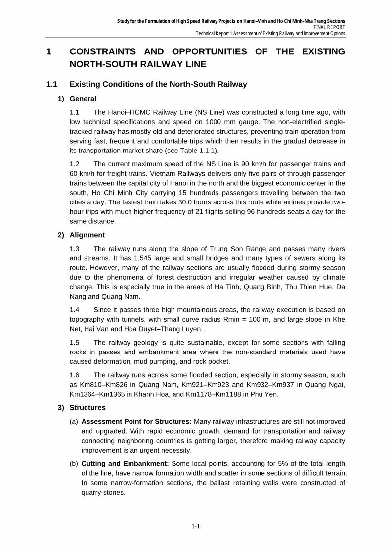
1.1 The Hanoi–HCMC Railway Line (NS Line) was constructed a long time ago, with low technical specifications and speed on 1000 mm gauge. The non-electrified single-tracked railway has mostly old and deteriorated structures, preventing train operation from serving fast, frequent and comfortable trips which then results in the gradual decrease in its transportation market share (see Table 1.1.1).
1.2 The current maximum speed of the NS Line is 90 km/h for passenger trains and 60 km/h for freight trains. Vietnam Railways delivers only five pairs of through passenger trains between the capital city of Hanoi in the north and the biggest economic center in the south, Ho Chi Minh City carrying 15 hundreds passengers travelling between the two cities a day. The fastest train takes 30.0 hours across this route while airlines provide two-hour trips with much higher frequency of 21 flights selling 96 hundreds seats a day for the same distance.
2) Alignment
1.3 The railway runs along the slope of Trung Son Range and passes many rivers and streams. It has 1,545 large and small bridges and many types of sewers along its route. However, many of the railway sections are usually flooded during stormy season due to the phenomena of forest destruction and irregular weather caused by climate change. This is especially true in the areas of Ha Tinh, Quang Binh, Thu Thien Hue, Da Nang and Quang Nam.
1.4 Since it passes three high mountainous areas, the railway execution is based on topography with tunnels, with small curve radius Rmin = 100 m, and large slope in Khe Net, Hai Van and Hoa Duyet–Thang Luyen.
1.5 The railway geology is quite sustainable, except for some sections with falling rocks in passes and embankment area where the non-standard materials used have caused deformation, mud pumping, and rock pocket.
1.6 The railway runs across some flooded section, especially in stormy season, such as Km810–Km826 in Quang Nam, Km921–Km923 and Km932–Km937 in Quang Ngai, Km1364–Km1365 in Khanh Hoa, and Km1178–Km1188 in Phu Yen.
3) Structures
(a) Assessment Point for Structures: Many railway infrastructures are still not improved and upgraded. With rapid economic growth, demand for transportation and railway connecting neighboring countries is getting larger, therefore making railway capacity improvement is an urgent necessity.
(b) Cutting and Embankment: Some local points, accounting for 5% of the total length of the line, have narrow formation width and scatter in some sections of difficult terrain. In some narrow-formation sections, the ballast retaining walls were constructed of quarry-stones.
Study for the Formulation of High Speed Railway Projects on Hanoi–Vinh and Ho Chi Minh–Nha Trang Sections FINAL REPORT Technical Report 1 Assessment of Existing Railway and Improvement Options
1-2
1.7 With regard to geology and hydrology of track formation, many formation sections on the existing railway are of weak geology that causes track formation to be unstable (e.g., falling rocks, stones concentrated on the pass area). This weak track foundation leads to subsidence.
(c) Bridge: In the anti-French and the anti-American resistance wars, the railway line was substantially destroyed, making it non-operational for some period. After the wars, the line was rehabilitated or repaired, but only to resume train operation. It has not been adequately maintained or repaired, including many weak bridges that remain unimproved.
1.8 The entire Hanoi–Ho Chi Minh City Railway Line includes 1,454 bridges with a total length of 36,332 m. In the years before 2008, projects for improving, upgrading and rehabilitating existing and building new bridges were carried out and have improved 756 bridges. The remaining 698 bridges, however, have not been funded.
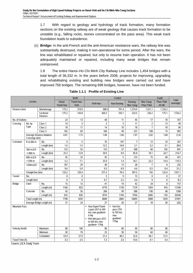
Table 1.1.1 Profile of Existing Line
Section North Central South
Total (average) Hanoi-
Thanh Hoa Thanh Hoa-
Vinh Vinh-Hue Hue-Danang
Danang- Nha Trang
Nha Trang- Phan Thiet
Phan Thiet -HCMC
Distance (km) kilometerage 175.2 319.0 688.3 791.4 1,314.9 1,551.1 1,726.2 -
Sectional Distance
175.2 143.8 369.3 103.1 523.5 236.2 175.1 1726.2
No. of Stations 23 13 40 11 45 17 18 167
Crossing No. by Type
Class 1 14 3 3 3 11 2 13 49
Class 2 18 11 14 10 18 7 18 96
Class 3 182 69 184 49 237 108 73 902
Average Distance between Crossings (km)
0.81 1.73 1.84 1.66 1.97 2.02 1.68 (1.6)
Curvature R≦300 m No. 9 5 76 147 7 13 10 267
Length (km) 1.6 1.5 12.5 14.8 2.1 3.2 3.1 38.8
300 m≦R <800 m
No. 123 55 153 37 308 60 105 841
Length (km) 25.3 12.8 39.0 9.0 85.8 18.1 24.7 214.7
800 m≦R <1200 m
No. 45 33 92 5 123 75 48 421
Length (km) 5.2 7.1 25.9 1.4 34.1 22.2 14.4 110.3
1200m≦R No. 107 29 40 13 28 7 8 232
Length (km) 9.6 5.9 9.3 0.9 4.6 0.5 0.4 31.2
Straight line (km) 133.2 120.4 277.3 78.3 397.5 192 132.4 1331.1
Tunnel No. 0 0 5 9 13 0 0 27
Length (km) 0 0 0.7 3.2 4.4 0 0 8.3
Bridge Steel No. 15 13 41 14 42 24 8 157
Length (m) 1166 823 4770 1139 7129 1303 916 17246
Concrete No. 43 56 284 99 588 190 48 1308
Length (m) 632 836 3919 1744 9766 2606 743 20246
Total Length (m) 1798 1659 8689 2883 16895 3908 1659 37491
Average Bridge Length (m) 31 24 27 26 27 18 30 (26)
Mountain Pass Hoa Duyet-Thanh Luyen (357 to 369 km, max gradient= 6 ‰)
Khe Net pass (415 to 420 km, max gradient= 17‰)
Hai Van pass (755 to 765 km, max gradient= 17‰)
Velocity (km/h) Maximum 80 100 80 80 90 80 80 -
Minimum 30 70 25 30 50 60 40
Scheduled 53.9 57.9 51.2 40.2 52.6 58.1 51.5 -
Travel Time (h) 3.3 2.5 7.2 2.6 10.0 4.1 3.4 -
Source: JICA Study Team
Study for the Formulation of High Speed Railway Projects on Hanoi–Vinh and Ho Chi Minh–Nha Trang Sections FINAL REPORT
Technical Report 1 Assessment of Existing Railway and Improvement Options
1-3
Notes: 1) The level crossings are classified according to the grade of the crossing roads. The first class intersects with the class 3 trunk-road or higher road, class 2 intersects with class 4 road and class 5 or miner road, and class 3 means the other level crossings not listed class 1 and class 2 above. The total number of level crossing is 2,439 including the 1,047 authorized level-crossings and the other 1,392 non-approved level-crossings.
1.9 These unimproved bridges contributed to the current speed restrictions and problems of safety along the railway line. Therefore, the bridge improvement projects should be continued from now.
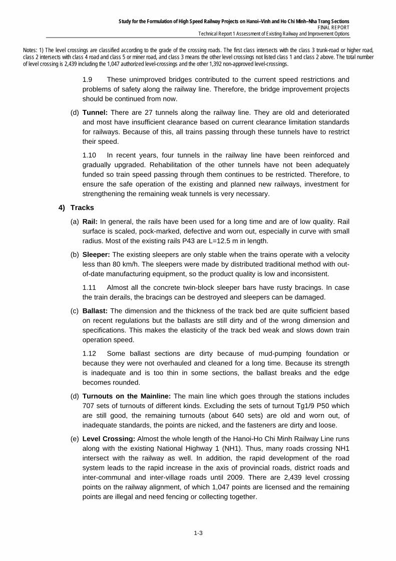
(d) Tunnel: There are 27 tunnels along the railway line. They are old and deteriorated and most have insufficient clearance based on current clearance limitation standards for railways. Because of this, all trains passing through these tunnels have to restrict their speed.
1.10 In recent years, four tunnels in the railway line have been reinforced and gradually upgraded. Rehabilitation of the other tunnels have not been adequately funded so train speed passing through them continues to be restricted. Therefore, to ensure the safe operation of the existing and planned new railways, investment for strengthening the remaining weak tunnels is very necessary.
4) Tracks
(a) Rail: In general, the rails have been used for a long time and are of low quality. Rail surface is scaled, pock-marked, defective and worn out, especially in curve with small radius. Most of the existing rails P43 are L=12.5 m in length.
(b) Sleeper: The existing sleepers are only stable when the trains operate with a velocity less than 80 km/h. The sleepers were made by distributed traditional method with out-of-date manufacturing equipment, so the product quality is low and inconsistent.
1.11 Almost all the concrete twin-block sleeper bars have rusty bracings. In case the train derails, the bracings can be destroyed and sleepers can be damaged.
(c) Ballast: The dimension and the thickness of the track bed are quite sufficient based on recent regulations but the ballasts are still dirty and of the wrong dimension and specifications. This makes the elasticity of the track bed weak and slows down train operation speed.
1.12 Some ballast sections are dirty because of mud-pumping foundation or because they were not overhauled and cleaned for a long time. Because its strength is inadequate and is too thin in some sections, the ballast breaks and the edge becomes rounded.
(d) Turnouts on the Mainline: The main line which goes through the stations includes 707 sets of turnouts of different kinds. Excluding the sets of turnout Tg1/9 P50 which are still good, the remaining turnouts (about 640 sets) are old and worn out, of inadequate standards, the points are nicked, and the fasteners are dirty and loose.
(e) Level Crossing: Almost the whole length of the Hanoi-Ho Chi Minh Railway Line runs along with the existing National Highway 1 (NH1). Thus, many roads crossing NH1 intersect with the railway as well. In addition, the rapid development of the road system leads to the rapid increase in the axis of provincial roads, district roads and inter-communal and inter-village roads until 2009. There are 2,439 level crossing points on the railway alignment, of which 1,047 points are licensed and the remaining points are illegal and need fencing or collecting together.
Study for the Formulation of High Speed Railway Projects on Hanoi–Vinh and Ho Chi Minh–Nha Trang Sections FINAL REPORT Technical Report 1 Assessment of Existing Railway and Improvement Options
1-4
1.13 There are many illegal roads on the railway line which are opened by local residents and do not follow any technical standards. These crossings are often made of several concrete slabs or made of ballast or aggregate. There are neither checkrails nor level crossing boards at many areas.
5) Layout Density of Stations
1.14 The layout density of stations in the line section is not uniform, which means that the distance between stations and train operation time per section is also not uniform. Sections with non-uniform distances cause the differences in train operation time, difficulty in route establishment, and limited capacity of train operation because the time for stopping, waiting, avoiding and passing of the train is increased. Sections with 12–14 km distance and especially those with > 14 km need a long period of time for train operation. It is necessary to review the symmetric capacity to respond to the required capacity of these sections.
(i) In the Hanoi–Vinh-Dong Hoi–Da Nang Sections, the number of sections ≤ 6 km ranges from 14.3% to 17.4% and the number of sections > 14 km ranges from 4.4% to 10.7%. The average distance between stations is from 8.82 km to 9.63 km.
(ii) In the Da Nang–Dieu Tri Section, there is no section ≤ 6 km;the number of sections 6–8 km long is 8.0%, while sections of 12–14 km are 19.2%, and sections of more than 14 km are also 19.2%. The average distance between stations is 11.26 km.
(iii) In the Dieu Tri–Nha Trang–Sai Gon Section, the number of sections ≤ 6 km only ranges from 5.6% to 8.6% and the number of sections > 14 km ranges from 31.4% to 33.3%. The average distance between stations is from 11.75 km to 12.19 km.
6) Signaling and Communication Systems
(a) Signaling System: The signaling system is critically important for ensuring safety in railway operations. A trivial human error may cause a fatal accident on a single track railway or in station premises without an adequate safety system. The current signaling system of the Hanoi–HCMC Railway Line is found to be inadequate to back up human errors. The following systems should be installed as soon as possible:
(i) Electronic interlocking system with micro-processing devices;
(ii) Automatic block system which detects trains by a track circuit, especially in station premises;
(iii) Automatic train stop system to back up driver’s failure; and
(iv) Automatic level crossing to reduce collisions with cars and motorcycles.
(b) Communication System: With regard to the communication system, the existing system is enough to operate the single track railway system. On-going and planned projects should be implemented on schedule and customer-oriented systems such as a ticket booking system should be reinforced.
7) Rolling Stock and Maintenance Facilities
(a) Rolling stock: Railways in Vietnam are not electrified, so all train formations consist of locomotives with diesel engines and some cars, passenger coaches and freight wagons. Almost all these rolling stocks are the old and heavy types, made up of thick steel and have a solid skeleton structure.
Study for the Formulation of High Speed Railway Projects on Hanoi–Vinh and Ho Chi Minh–Nha Trang Sections FINAL REPORT
Technical Report 1 Assessment of Existing Railway and Improvement Options
1-5
1.15 There are great differences between the technology of old trains and that of the recent EMUs. The old train type’s body material is heavy steel while the EMU’s is light stainless steel or aluminum alloy. The bogie’s spring is coils for the old type and air suspensions for the EMU. Old motors are direct current while the new types are AC induction motors. It is necessary to acquire these new technologies for the operation of a modern high speed railway. The on-going projects for urban railways in Hanoi and Ho Chi Minh are good opportunities for acquiring such technologies.
(b) Maintenance Facilities: The maintenance facilities of the existing railway are also backward and investment for this purpose is inadequate. Employees work in narrow spaces and under dangerous circumstances. Improvement of maintenance facilities is vital for the improvement of rolling stock.
8) Railway Operation
1.16 The North-South line earns more than 50 % of entire Vietnam Railways annual revenue making overall financial figure of the organization in surplus. Vietnam Railways currently operates in total 32 trains a day, 20 for passengers 12 for freights. Out of the 20 passenger trains 10 express trains run all through the North South line between Hanoi and Saigon. The other 10 are locally operated connecting major cities along the line. 10 freight trains run across the entire North-South line with two local ones between Bim Son and Dung Ha in the north. The train operation diagram is restricted by the line capacity between stations because the North-South Line is single-track. The lowest capacity is in the Hai Van Pass and the Khe Net Pass sections. Those sections require a long running time because of the steep gradient and the tunnels with speed restriction.
Study for the Formulation of High Speed Railway Projects on Hanoi–Vinh and Ho Chi Minh–Nha Trang Sections FINAL REPORT Technical Report 1 Assessment of Existing Railway and Improvement Options
1-6
Hanoi Station Vinh Station
Boarding and Alighting Passengers
Railway sections in Hanoi Urban Area Railway crossing Controlled by Security Staff with Slide Gate and Alarm System
Railway crossing Controlled by Security Staff with Cross Gate and Alarm System
Railway crossing Controlled by Security Staff with crossing Gate
Railway crossing with only Sign of Caution Railway crossing (likely illegal)
An Example of Bridge Restoration Typical Tunnel Condition
Source: JICA Study Team
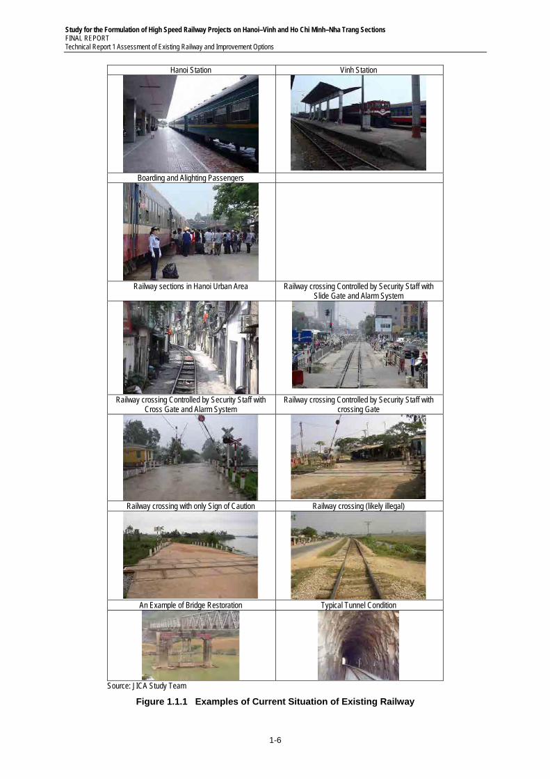
Figure 1.1.1 Examples of Current Situation of Existing Railway
Study for the Formulation of High Speed Railway Projects on Hanoi–Vinh and Ho Chi Minh–Nha Trang Sections FINAL REPORT
Technical Report 1 Assessment of Existing Railway and Improvement Options
1-7
1.2 Main Bottlenecks in Existing Railway
1) General Assessment and Main Bottlenecks
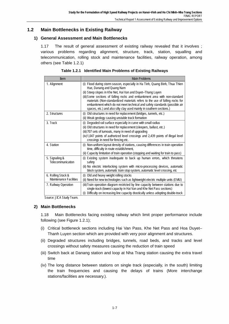
1.17 The result of general assessment of existing railway revealed that it involves ; various problems regarding alignment, structure, track, station, squalling and telecommunication, rolling stock and maintenance facilities, railway operation, among others (see Table 1.2.1)
Table 1.2.1 Identified Main Problems of Existing Railways
Item Main Problems
1. Alignment (i) Flood during storm season, especially in Ha Tinh, Quang Binh, Thua Thien Hue, Danang and Quang Nam
(ii) Steep slopes in Khe Net, Hai Van and Duyet–Thang Luyen (iii) Some sections of falling rocks and embankment area with non-standard
materials (Non-standardized materials refers to the use of falling rocks for embankment which do not meet technical and safety standards (possible air spaces, etc.) and also silty clay used mainly in southern sections.)
2. Structures (i) Old structures in need for replacement (bridges, tunnels, etc.) (ii) Weak geology causing unstable track formation
3. Track (i) Degraded rail surface especially in curve with small radius (ii) Old structures in need for replacement (sleepers, ballast, etc.) (iii) 707 sets of turnouts, many in need of upgrading (iv) 1,047 points of authorized level crossings and 2,439 points of illegal level
crossings in need for fencing etc.
4. Station (i) Non-uniform layout density of stations, causing differences in train operation time, difficulty in route establishment,
(ii) Capacity limitation of train operation (stopping and waiting for train to pass) 5. Signaling &
Telecommunication (i) Existing system inadequate to back up human errors, which threatens
safety (ii) No electric interlocking system with micro-processing devices, automatic
block system, automatic train stop system, automatic level crossing, etc 6. Rolling Stock &
Maintenance Facilities (i) Old and heavy weight rolling stocks (ii) Need for new technologies such as lightweight electric multiple units (EMU)
7. Railway Operation (iii) Train operation diagram restricted by line capacity between stations due to single-track (lowest capacity in Hai Van and Khe Net Pass sections)
(i) Difficulty on increasing line capacity drastically unless adopting double-track Source: JICA Study Team.
2) Main Bottlenecks
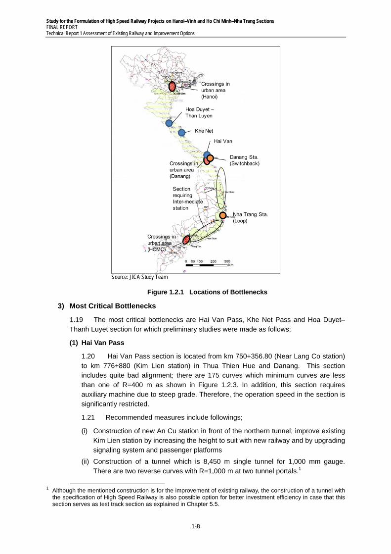
1.18 Main Bottlenecks facing existing railway which limit proper performance include following (see Figure 1.2.1);
(i) Critical bottleneck sections including Hai Van Pass, Khe Net Pass and Hoa Duyet–Thanh Luyen section which are provided with very poor alignment and structures.
(ii) Degraded structures including bridges, tunnels, road beds, and tracks and level crossings without safety measures causing the reduction of train speed
(iii) Switch back at Danang station and loop at Nha Trang station causing the extra travel time
(iv) The long distance between stations on single track (especially, in the south) limiting the train frequencies and causing the delays of trains (More interchange stations/facilities are necessary.).
Study for the Formulation of High Speed Railway Projects on Hanoi–Vinh and Ho Chi Minh–Nha Trang Sections FINAL REPORT Technical Report 1 Assessment of Existing Railway and Improvement Options
1-8
Hoa Duyet –Than Luyen
Khe Net
Hai Van
Danang Sta.(Switchback)
Nha Trang Sta.(Loop)
Crossings in urban area(Hanoi)
Crossings in urban area(HCMC)
Crossings in urban area(Danang)
Section requiring Inter-mediate station
Source: JICA Study Team
Figure 1.2.1 Locations of Bottlenecks
3) Most Critical Bottlenecks
1.19 The most critical bottlenecks are Hai Van Pass, Khe Net Pass and Hoa Duyet–Thanh Luyet section for which preliminary studies were made as follows;
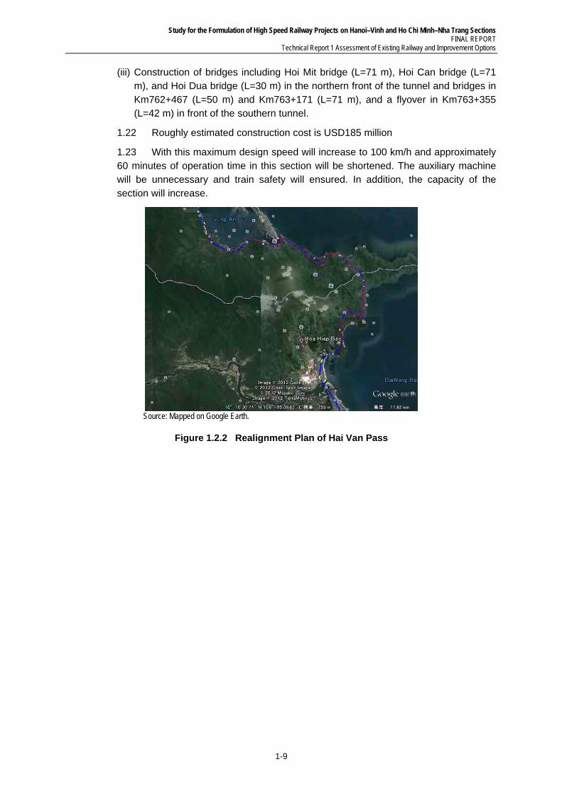
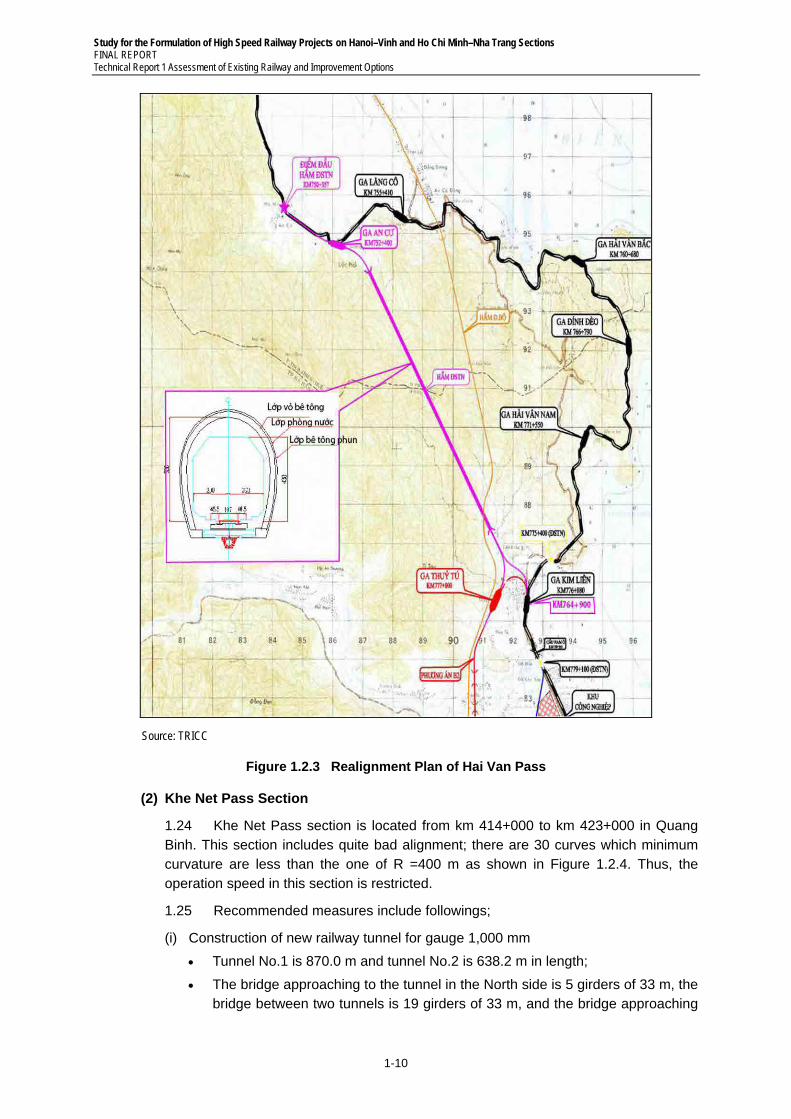
(1) Hai Van Pass
1.20 Hai Van Pass section is located from km 750+356.80 (Near Lang Co station) to km 776+880 (Kim Lien station) in Thua Thien Hue and Danang. This section includes quite bad alignment; there are 175 curves which minimum curves are less than one of R=400 m as shown in Figure 1.2.3. In addition, this section requires auxiliary machine due to steep grade. Therefore, the operation speed in the section is significantly restricted.
1.21 Recommended measures include followings;
(i) Construction of new An Cu station in front of the northern tunnel; improve existing Kim Lien station by increasing the height to suit with new railway and by upgrading signaling system and passenger platforms
(ii) Construction of a tunnel which is 8,450 m single tunnel for 1,000 mm gauge. There are two reverse curves with R=1,000 m at two tunnel portals.1
1 Although the mentioned construction is for the improvement of existing railway, the construction of a tunnel with
the specification of High Speed Railway is also possible option for better investment efficiency in case that this section serves as test track section as explained in Chapter 5.5.
Study for the Formulation of High Speed Railway Projects on Hanoi–Vinh and Ho Chi Minh–Nha Trang Sections FINAL REPORT
Technical Report 1 Assessment of Existing Railway and Improvement Options
1-9
(iii) Construction of bridges including Hoi Mit bridge (L=71 m), Hoi Can bridge (L=71 m), and Hoi Dua bridge (L=30 m) in the northern front of the tunnel and bridges in Km762+467 (L=50 m) and Km763+171 (L=71 m), and a flyover in Km763+355 (L=42 m) in front of the southern tunnel.
1.22 Roughly estimated construction cost is USD185 million
1.23 With this maximum design speed will increase to 100 km/h and approximately 60 minutes of operation time in this section will be shortened. The auxiliary machine will be unnecessary and train safety will ensured. In addition, the capacity of the section will increase.
Source: Mapped on Google Earth.
Figure 1.2.2 Realignment Plan of Hai Van Pass
Study for the Formulation of High Speed Railway Projects on Hanoi–Vinh and Ho Chi Minh–Nha Trang Sections FINAL REPORT Technical Report 1 Assessment of Existing Railway and Improvement Options
1-10
Source: TRICC
Figure 1.2.3 Realignment Plan of Hai Van Pass
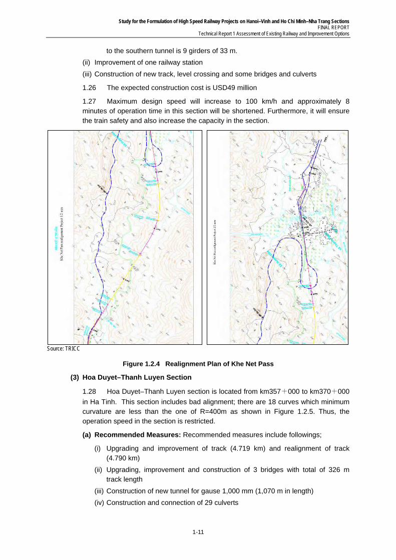
(2) Khe Net Pass Section
1.24 Khe Net Pass section is located from km 414+000 to km 423+000 in Quang Binh. This section includes quite bad alignment; there are 30 curves which minimum curvature are less than the one of R =400 m as shown in Figure 1.2.4. Thus, the operation speed in this section is restricted.
1.25 Recommended measures include followings;
(i) Construction of new railway tunnel for gauge 1,000 mm
Tunnel No.1 is 870.0 m and tunnel No.2 is 638.2 m in length;
The bridge approaching to the tunnel in the North side is 5 girders of 33 m, the bridge between two tunnels is 19 girders of 33 m, and the bridge approaching
Study for the Formulation of High Speed Railway Projects on Hanoi–Vinh and Ho Chi Minh–Nha Trang Sections FINAL REPORT
Technical Report 1 Assessment of Existing Railway and Improvement Options
1-11
to the southern tunnel is 9 girders of 33 m.
(ii) Improvement of one railway station
(iii) Construction of new track, level crossing and some bridges and culverts
1.26 The expected construction cost is USD49 million
1.27 Maximum design speed will increase to 100 km/h and approximately 8 minutes of operation time in this section will be shortened. Furthermore, it will ensure the train safety and also increase the capacity in the section.
Source: TRICC
Figure 1.2.4 Realignment Plan of Khe Net Pass
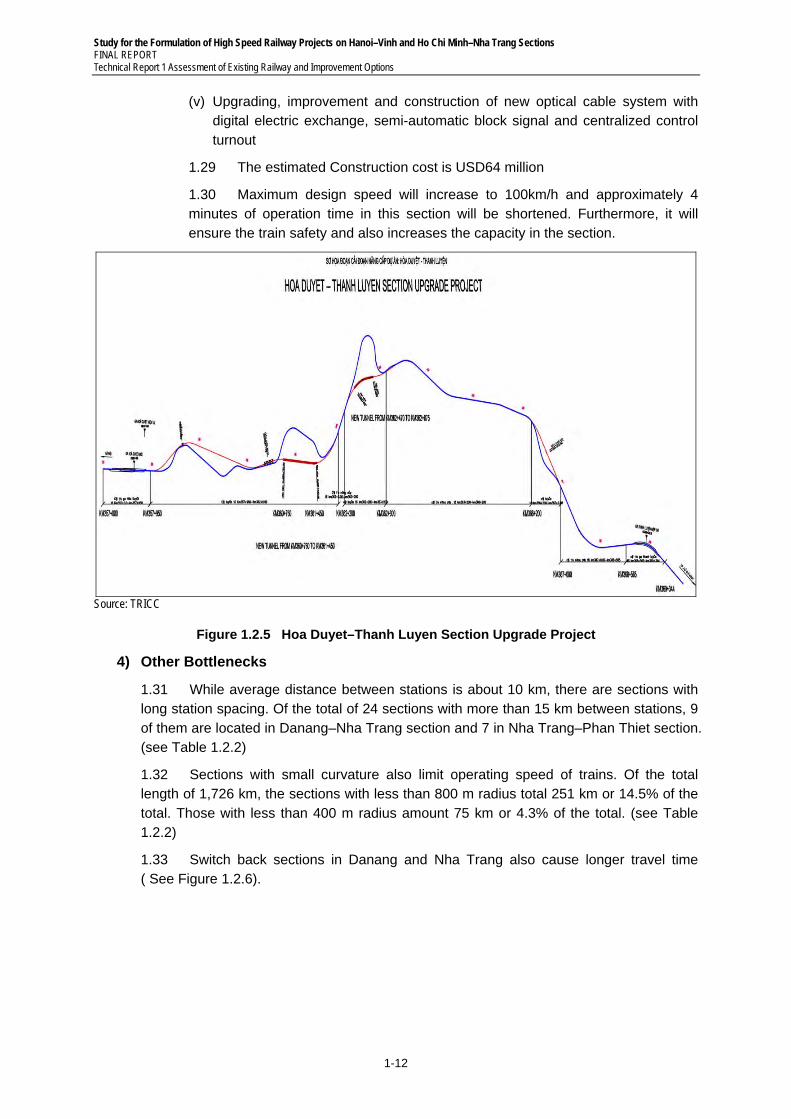
(3) Hoa Duyet–Thanh Luyen Section
1.28 Hoa Duyet–Thanh Luyen section is located from km357+000 to km370+000
in Ha Tinh. This section includes bad alignment; there are 18 curves which minimum curvature are less than the one of R=400m as shown in Figure 1.2.5. Thus, the operation speed in the section is restricted.
(a) Recommended Measures: Recommended measures include followings;
(i) Upgrading and improvement of track (4.719 km) and realignment of track (4.790 km)
(ii) Upgrading, improvement and construction of 3 bridges with total of 326 m track length
(iii) Construction of new tunnel for gause 1,000 mm (1,070 m in length)
(iv) Construction and connection of 29 culverts
Study for the Formulation of High Speed Railway Projects on Hanoi–Vinh and Ho Chi Minh–Nha Trang Sections FINAL REPORT Technical Report 1 Assessment of Existing Railway and Improvement Options
1-12
(v) Upgrading, improvement and construction of new optical cable system with digital electric exchange, semi-automatic block signal and centralized control turnout
1.29 The estimated Construction cost is USD64 million
1.30 Maximum design speed will increase to 100km/h and approximately 4 minutes of operation time in this section will be shortened. Furthermore, it will ensure the train safety and also increases the capacity in the section.
Source: TRICC
Figure 1.2.5 Hoa Duyet–Thanh Luyen Section Upgrade Project
4) Other Bottlenecks
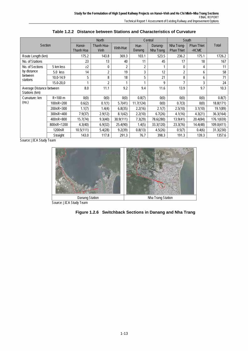
1.31 While average distance between stations is about 10 km, there are sections with long station spacing. Of the total of 24 sections with more than 15 km between stations, 9 of them are located in Danang–Nha Trang section and 7 in Nha Trang–Phan Thiet section. (see Table 1.2.2)
1.32 Sections with small curvature also limit operating speed of trains. Of the total length of 1,726 km, the sections with less than 800 m radius total 251 km or 14.5% of the total. Those with less than 400 m radius amount 75 km or 4.3% of the total. (see Table 1.2.2)
1.33 Switch back sections in Danang and Nha Trang also cause longer travel time ( See Figure 1.2.6).
Study for the Formulation of High Speed Railway Projects on Hanoi–Vinh and Ho Chi Minh–Nha Trang Sections FINAL REPORT
Technical Report 1 Assessment of Existing Railway and Improvement Options
1-13
Table 1.2.2 Distance between Stations and Characteristics of Curvature
Section North Central South
Total Hanoi- Thanh Hoa
Thanh Hoa- Vinh
Vinh-Hue Hue-
Danang Danang-
Nha Trang Nha Trang- Phan Thiet
Phan Thiet -HCMC
Route Length (km) 175.2 143.8 369.3 103.1 523.5 236.2 175.1 1726.2 No. of Stations 23 13 40 11 45 17 18 167 No. of Sections by distance between stations
5 km less z2 0 2 2 1 0 4 11 5.0 less 14 2 19 3 12 2 6 58 10.0-14.9 5 8 18 5 21 8 6 71 15.0-20,0 1 2 1 1 9 7 3 24
Average Distance between Stations (km)
8.0 11.1 9.2 9.4 11.6 13.9 9.7 10.3
Curvature: km (no.)
R<100 m 0(0) 0(0) 0(0) 0.8(7) 0(0) 0(0) 0(0) 0.8(7) 100≤R<200 0.6(2) 0.1(1) 5.7(41) 11.7(124) 0(0) 0.7(3) 0(0) 18.8(171) 200≤R<300 1.1(7) 1.4(4) 6.8(35) 2.2(16) 2.1(7) 2.5(10) 3.1(10) 19.1(89) 300≤R<400 7.9(37) 2.9(12) 8.1(42) 2.2(10) 6.7(26) 4.1(16) 4.3(21) 36.3(164) 400≤R<800 15.7(74) 9.3(40) 30.9(111) 7.3(29) 78.6(280) 13.9(41) 20.4(84) 176.1(659) 800≤R<1200 4.3(40) 6.9(32) 25.4(90) 1.4(5) 33.3(120) 23.3(76) 14.4(48) 109.0(411)
1200≤R 10.5(111) 5.4(28) 9.2(39) 0.8(13) 4.5(26) 0.5(7) 0.4(6) 31.3(230) Straight 143.0 117.8 291.3 76.7 398.3 191.3 139.3 1357.6
Source: JICA Study Team
Danang Station Nha Trang Station
Source: JICA Study Team
Figure 1.2.6 Switchback Sections in Danang and Nha Trang
Study for the Formulation of High Speed Railway Projects on Hanoi–Vinh and Ho Chi Minh–Nha Trang Sections FINAL REPORT Technical Report 1 Assessment of Existing Railway and Improvement Options
1-14
1.3 Opportunities and Constrains to Improvement of Existing Line
1) Overview
1.34 While existing railway involves a number of bottlenecks, various improvement measures are on-going and planned by the Government. It is also expected that the existing railway can be upgraded to provide much higher level of services than the current level, such as increase in operating speed to 200 km/h both for passenger and freight services through double and widening existing tracks. Dual gauge operation is also mentioned.
1.35 If these measures can be justified, it will become a competitive alternative to development of new high-speed line. Therefore, it is considered necessary and importance to analyze possibility and constraint of upgrading the existing railway up to the most appropriate level. Following three basic points which were also raised and discussed in the National Assembly are analyzed in the study;
(i) Converting to dual gauge for entire section of existing railway
(ii) Upgrading of existing railway to accommodate train operation at maximum speed of 200 km/h.
(iii) Mixed operation of passenger and freight trains at maximum speed of 200 km/h.
2) Analysis of Conversion of Existing Railway to Dual Gauge
1.36 The installation of dual gauge for the entire section, which is one of the alternatives for North South railway development discussed in Vietnam, is analyzed and the result is shown in the following paragraphs.
(1) Application Practices of Dual Gauge
1.37 In Europe and Japan, generally dual gauge is applied at points where tracks with different gauges meet and there are few cases dual gauge is applied for the entire route. Dual gauge is used only for a part of a section because of engendered restrictions on track layout and train speed on the standard-gauge line (also in Vietnam, dual gauge is applied for two lines connecting to China with total length of 220 km).
(2) Restriction of Speed Limit
1.38 While the purpose of dual gauge is to facilitate combined operation of high speed passenger train on standard gauge and freight train operation on narrow gauge, under the condition of mixed operation, high speed operation is not achievable (for example, in Akita Shinkansen line, where dual gauge is applied, average speed is only 85 km/h though maximum speed is 130 km/h).
1.39 In addition, the speed limit is engendered on turnouts because of the reasons below (only limited improvement of operation speed is achievable by introducing dual gauge; the improvement of alignment is necessary for realizing faster speed);
Turnouts have complicated structures. Non-availability of scissors, diamond crossing and special turnouts restricts the track layout.
Combinations of standard- and narrow-gauge tracks on the main line side and those on the branch side necessitate 28 different turnouts, which require design numbers for turnouts to be limited.
Study for the Formulation of High Speed Railway Projects on Hanoi–Vinh and Ho Chi Minh–Nha Trang Sections FINAL REPORT
Technical Report 1 Assessment of Existing Railway and Improvement Options
1-15
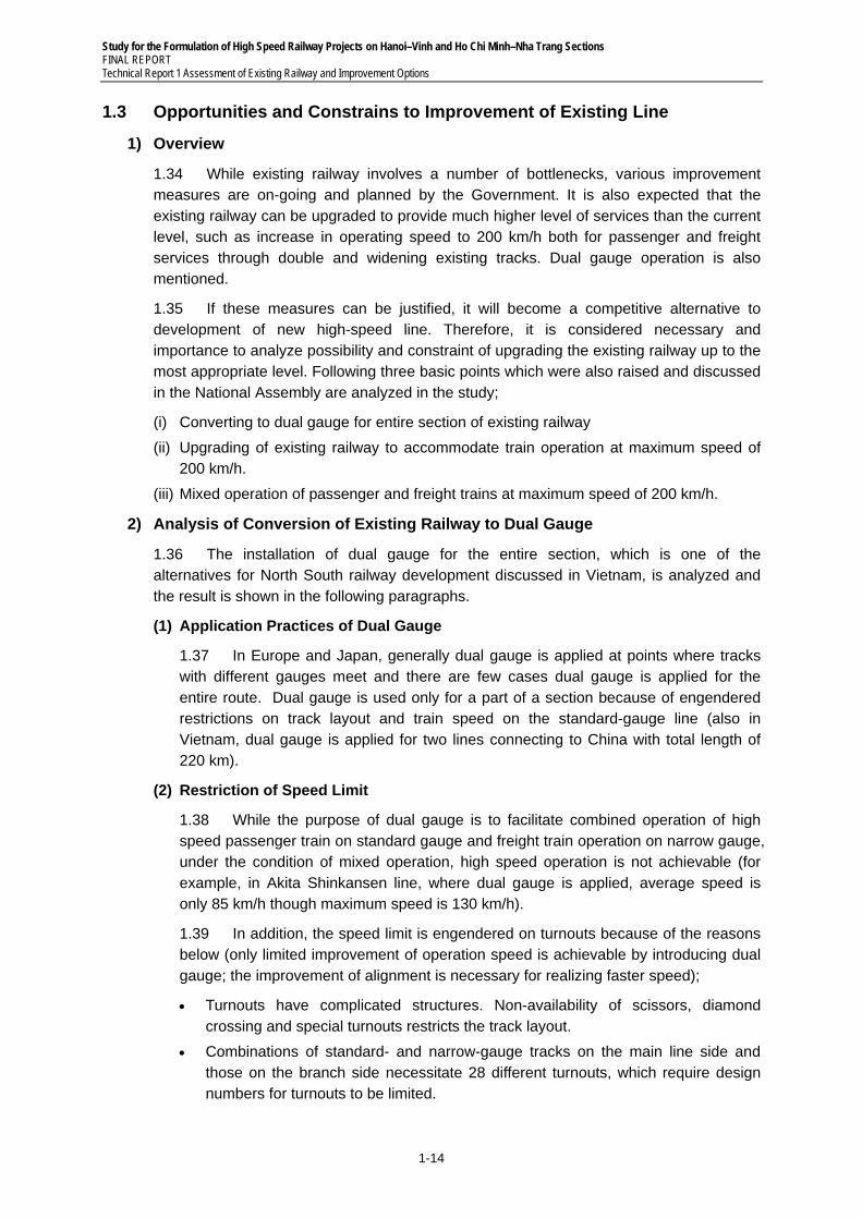
The speed on the straight side of the turnout in Figure 1.3.1 is limited to 80–90 km/h while seven turnouts out of 28 can be used for 120 km/h.
Dual Gauge Turnout Loose-heel joint
Source: JICA Study Team
Figure 1.3.1 Dual Gauge (Photo)
(3) Operational Suspension
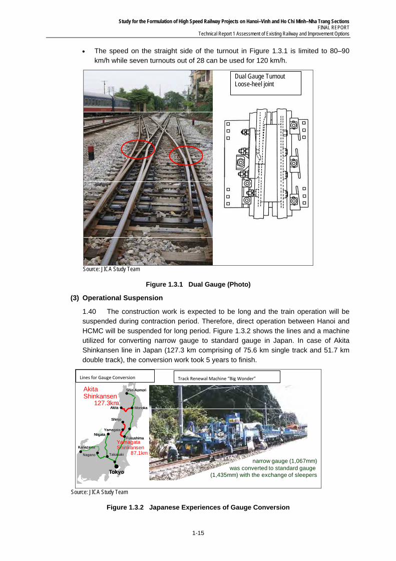
1.40 The construction work is expected to be long and the train operation will be suspended during contraction period. Therefore, direct operation between Hanoi and HCMC will be suspended for long period. Figure 1.3.2 shows the lines and a machine utilized for converting narrow gauge to standard gauge in Japan. In case of Akita Shinkansen line in Japan (127.3 km comprising of 75.6 km single track and 51.7 km double track), the conversion work took 5 years to finish.
NiigataFukushima
Takasaki
Yamagata
Nagano
Akita
Shinjo
Kanazawa
Shin-Aomori
Morioka
NiigataFukushima
Takasaki
Yamagata
Nagano
Akita
Shinjo
Kanazawa
Shin-Aomori
Morioka
Akita Shinkansen
127.3km
Yamagata Shinkansen
87.1km Conventional narrow gauge (1,067mm)
was converted to standard gauge (1,435mm) with the exchange of sleepers
Lines for Gauge Conversion Track Renewal Machine “Big Wonder”
Source: JICA Study Team
Figure 1.3.2 Japanese Experiences of Gauge Conversion
Study for the Formulation of High Speed Railway Projects on Hanoi–Vinh and Ho Chi Minh–Nha Trang Sections FINAL REPORT Technical Report 1 Assessment of Existing Railway and Improvement Options
1-16
(4) Construction Works
1.41 Most bridges of existing railway should be reconstructed due to the shift of load center.
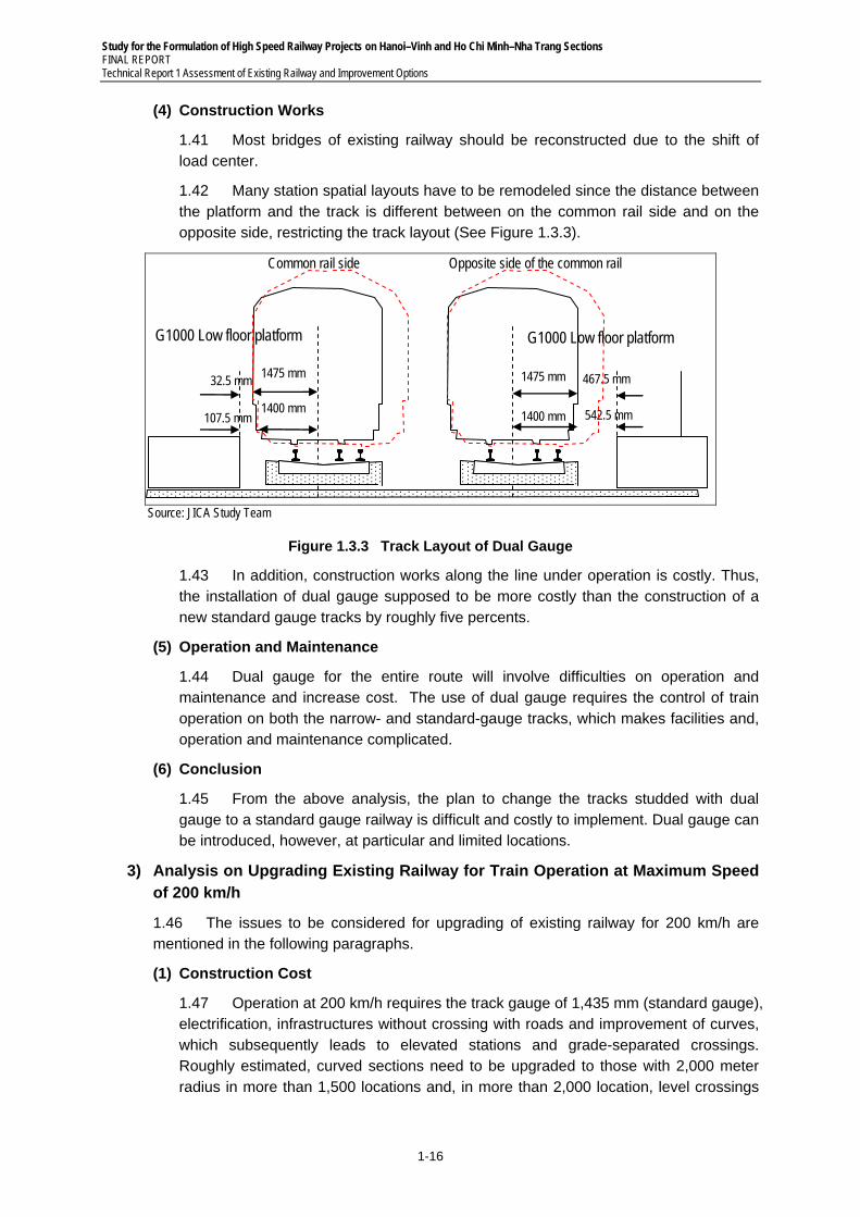
1.42 Many station spatial layouts have to be remodeled since the distance between the platform and the track is different between on the common rail side and on the opposite side, restricting the track layout (See Figure 1.3.3).
G1000 Low floor platform G1000 Low floor platform
1475 mm 32.5 mm 1475 mm 467.5 mm
1400 mm 107.5 mm 1400 mm 542.5 mm
Common rail side Opposite side of the common rail
Source: JICA Study Team
Figure 1.3.3 Track Layout of Dual Gauge
1.43 In addition, construction works along the line under operation is costly. Thus, the installation of dual gauge supposed to be more costly than the construction of a new standard gauge tracks by roughly five percents.
(5) Operation and Maintenance
1.44 Dual gauge for the entire route will involve difficulties on operation and maintenance and increase cost. The use of dual gauge requires the control of train operation on both the narrow- and standard-gauge tracks, which makes facilities and, operation and maintenance complicated.
(6) Conclusion
1.45 From the above analysis, the plan to change the tracks studded with dual gauge to a standard gauge railway is difficult and costly to implement. Dual gauge can be introduced, however, at particular and limited locations.
3) Analysis on Upgrading Existing Railway for Train Operation at Maximum Speed of 200 km/h
1.46 The issues to be considered for upgrading of existing railway for 200 km/h are mentioned in the following paragraphs.
(1) Construction Cost
1.47 Operation at 200 km/h requires the track gauge of 1,435 mm (standard gauge), electrification, infrastructures without crossing with roads and improvement of curves, which subsequently leads to elevated stations and grade-separated crossings. Roughly estimated, curved sections need to be upgraded to those with 2,000 meter radius in more than 1,500 locations and, in more than 2,000 location, level crossings
Study for the Formulation of High Speed Railway Projects on Hanoi–Vinh and Ho Chi Minh–Nha Trang Sections FINAL REPORT
Technical Report 1 Assessment of Existing Railway and Improvement Options
1-17
at roads need to be grade separated. The cost of electrification shall also be added to the construction cost.
1.48 The 1,435 mm gauge track to be added to the existing single track sections shall be constructed first, on which operation of single-track shall be implemented while the existing 1 m gauge lines shall be demolished. After removing the existing 1 m gauge track, other construction works required for the 1,435 mm gauge shall be implemented. To smoothly transfer operation from the 1m gauge to 1,435 mm gauge, therefore, facilities for these two different gauges shall be maintained for rolling stocks at depots and stations. This shall increase the construction cost.
1.49 The total cost will amount to approximately 40 billion US dollars (estimated based on the cost for Option B2 additionally taking the increase of alignments improved, rolling stocks, electrical equipments, deports and other infrastructures compared to Option B2 into account), roughly equal to the cost to construct a high-speed railway for 200 km/h operation.
(2) Construction Period
1.50 The period of construction work would become around14–23 years, given the conditions stated in above, long route length and budgetary ability of work execution.
Survey, designing and order placing: 2 to 3 years
Construction of additional track: 5 to 8 years
Preparation for 1,435 mm gauge single track operation: 1 to 2 years
Construction work at the existing line: 5 to 8 years
Preparation for double-track operation: 1 to 2 years
Total 14 to 23 years
1.51 As the construction work is executed while the line is in service, trains cannot run at regular operating speed in some sections where train speed in limited.
(3) Possibility for further Upgrading up to 300 km/h
1.52 If the plan of upgrading the exiting railways to 200 km/h is adopted, it is not conceivable to remodel railway again to 300 km/h railway system because of high construction cost and long construction period.
1.53 The increase in the speed of passenger trains is not possible either if the both of passenger and freight trains are operated on the same track.
4) Analysis on Mixed Operation of Passenger and Freight Trains at Maximum Speed of 200 km/h
1.54 The possibility of the mixed operation of passenger and freight train at 200 km/h is analyzed and the result is shown in the following paragraphs.
(1) Difficulty of 200 km/h Operation of Freight Trains
1.55 The current maximum speed of freight trains in the world is 120 km/h. On the other hand, in Germany, for example, freight trains were once operated at140 to 160 km/h although it has been dropped to 120 km/h because of the problems of profitability and security. For the following reasons, it is not the case in Europe that freight trains be operated mixed with high speed passenger trains in the same sections and time zones.
Study for the Formulation of High Speed Railway Projects on Hanoi–Vinh and Ho Chi Minh–Nha Trang Sections FINAL REPORT Technical Report 1 Assessment of Existing Railway and Improvement Options
1-18
1.56 Although the possibility of 120 km/h operation of freight trains is not necessarily be denied in view of the technical development in the future, the hurdles for that purpose are too high to adopt the 200 km/h operation of freight trains in Vietnam.
(2) Experiences in European Countries
1.57 Freight trains are operated mixed with high-speed passenger trains at some places in Europe under several conditions.
(a) Germany: Freight trains were once operated at 140 to 160 km/h in the Bremen-Stuttgart section (710 km) and the Hamburg-Munich section (779 km) from 1991, which was reduced to 120 km/h in 1995 due to low profitability.
(b) France: Freight trains are operated at a maximum speed of 270 km/h eight times a day to transport mails, parcels and newspapers with remodeled TGV cars on the TGV Southeastern line. However, France does not have an idea to operate freight trains excluding aforementioned TGV remodeled cars on the same lines with high-speed passenger trains, as there are problems related to train operation diagrams and the time zone required for maintenance work. Rather, France has an idea to construct new lines for high-speed freight trains.
(3) Problems related to the Security and the Train Operation Diagrams in the Mixed Operation of 200 km/h Passenger Trains and 120 km/h Freight Trains
1.58 The realistic maximum speed of the freight trains in Vietnam is considered to be 120 km/h However, in such condition, the mixed operation of 200 km/h passenger trains and 120 km/h freight trains has the following problems from the viewpoint of safety and train operation diagrams, suggesting the difficulty of its implementation
(a) Passenger Train Operation at 200 km/h
1.59 When the impact at train collisions and the forward visibility distance for train drivers are considered, it is recommendable for Vietnam to introduce the same security system as that of Shinkansen in Japan which has no level-crossings and the ATC system installed in.
1.60 In case of Japan, the forward visibility distance for drivers is specified as 600 m or over. For the Akita and Yamagata Shinkansen railways having road crossings, therefore, the operational speed is limited to 130 km/h or less, to ensure that trains can stop within the visibility distance when the emergency brake is applied. The Shinkansen trains run approximately 2 km after the emergency brake is applied at 200 km/h. It is of no use for drivers, therefore, to apply the emergency brake after noticing an abnormality ahead. This means that the ATC system is essential.
(b) Structure and Performance of Freight Trains
1.61 For high speed operation of freight train at 120 km/h, ATC system, which is a security system applied for Shinkansen, is need to be applied; the security devices and a high-reliability brake system for precise deceleration should be installed not only on locomotives but also on whole train-sets. On the other hand, container freight liner train system is also should be introduced for avoiding unexpected opens of door during operation and fall of cargo as well as breaks of
Study for the Formulation of High Speed Railway Projects on Hanoi–Vinh and Ho Chi Minh–Nha Trang Sections FINAL REPORT
Technical Report 1 Assessment of Existing Railway and Improvement Options
1-19
cargo car’s axle caused by excessive heat. Thus, the current VN freight transport system should be totally changed; new rolling stock should be procured for freight liner system and base yards should be constructed.
(c) Train Operation Diagrams
1.62 When trains at different speeds are operated on the same line, the larger the speed difference is, the greater the influence is on the train operation diagrams. Although this is not desirable, it does not mean the mixed operation is impossible.
1.63 At their presentation at UIC (International Union of Railways), those concerned with railways in Germany stated that the time zones for the operation of high-speed trains and freight trains should be separated, presumably by operating freight trains at night, which, although, would conflict with the night time maintenance work for 200 km/h operation of passenger trains
1.64 To extend the Shinkansen line to Hokkaido, three-rail tracks are laid through the Seikan tunnel in Japan. The initial train operation diagrams planned to run freight trains at night not to interfere with the Shinkansen trains. Under the current plan, however, freight trains are operated mixed with passenger trains with the speed of Shinkansen trains reduced to 140 km/h.
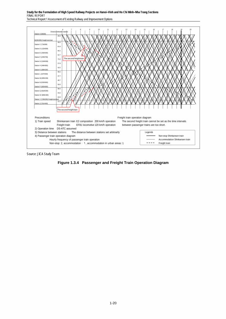
1.65 Considering these problems, the Study Team drew train operation diagrams to run 120 km/h freight trains mixed with 200 km/h passenger trains between Hanoi and Ho Chi Minh as shown in Figure 1.3.4. The operation diagrams are impractical as there is a great influence on passenger and freight trains.
Study for the Formulation of High Speed Railway Projects on Hanoi–Vinh and Ho Chi Minh–Nha Trang Sections FINAL REPORT Technical Report 1 Assessment of Existing Railway and Improvement Options
1-20
6Distance between stations
Station A (0k000)25.0
B(25K000) Freight terminal46.0
Station C (71K000)61.8
Station D (132K800)60.2
Station E (193K000)52.7
Station F (245K700)73.2
Station G (319K000)27.8
Station H (346K800)42.5
Station K (389K300)58.2
Station L (447K500)37.7
Station M (485K200)48.7
Station N (533K900)50.0
Station P (583K900)58.4
Station Q (642K300)43.0
Station W (685K300)43.9
Station Y (729K200) Freight terminal22.2
Station Z (751K400)
Preconditions Freight train operation diagram1) Train speed Shinkansen train E2 composition 200 km/h operation The second freight train cannot be set as the time intervals
Freight train EF81 locomotive120 km/h operation between passenger trains are too short.2) Operation time DS-ATC assumed3) Distance between stations The distance between stations set arbitrarily Legends
4) Passenger train operation diagram Non-stop Shinkansen train
Hourly frequency of passenger train operation Accommodation Shinkansen train
Non-stop: 2, accommodation:1, accommodation in urban areas: 1 Freight train
7 8 9 10 19 2016 17 1811 12 13 1514
The second freight train
The second freight train
Source: JICA Study Team
Figure 1.3.4 Passenger and Freight Train Operation Diagram

Study for the Formulation of High Speed Railway Projects on Hanoi–Vinh and Ho Chi Minh–Nha Trang Sections FINAL REPORT
Technical Report 1 Assessment of Existing Railway and Improvement Options
1-21
1.4 Alternative Improvement Options for the North-South Railway Line
1) Preparation of Alternative Improvement Options
1.66 It is essential for the existing railway line to be modernized to meet the growing demands of passenger and freight volume in the course of a fast expanding Vietnamese economic growth (as for future traffic demand, see chapter 4.2). It is also crucial for the 1,726 km railway line to be upgraded in order to survive fierce competition in the transportation market among various modes of transportation, i.e., rail, air, bus, car, truck and shipping.
1.67 There are multifold approaches to improve or upgrade existing non-electrified single track railway. Targets of improvement, therefore, have to be figured out first. The JICA Study Team has set up four possible upgrading or Improvement Options, namely A1, A2, B1 and B2.The targets of each options are as follows:2
(i) A1: Baseline, minimal improvement to ensure safe operation (ongoing and committed projects);
(ii) A2: Maximization of existing single track transportation capacity;
(iii) B1: Strengthening of transportation capacity through double tracking and increase in maximum operating speed to 120 km/h; and
(iv) B2: Double tracking with 1435 mm track gauge and electrification with maximum operating speed of 150 km/h or more (semi high speed). All the intersections of railway and road are grade-separated.
1.68 Combining the outcomes of the four basic options with that of HSR plans, it will be easy to assess any possible scenarios suggested by various sectors in Vietnam including the National Assembly.
1.69 Although, in the following paragraphs, these options are discussed for the entire North-south railway, practically, the most appropriate option (target improvement level) should be selected from them by section and phase.
2) Features of A1
(a) Objectives of Option A1: Option A1 is a baseline plan that consists of implementing ongoing and already committed improvement projects for the North-South Railway Line and other measures of minimum requirements to maintain safety levels of the structures as well as the current maximum operating speed of 90 km/h. This ongoing/committed option will reduce the schedule time between Hanoi and HCMC from the current 30.0 hours to 29.1 hours by the fastest train. This speed-up comes from the removal of speed-restricted sections currently imposed on the weak structures, such as old bridges, deteriorated tracks and pumping embankments.
(b) Scope of Option A1: Option A1 will consist of the following railway improvement projects and activities:
(i) Station Improvement: New waiting lines are added at seven stations, effective track lengths are expanded at seventeen stations and tracks are renewed at sixty eight stations.
(ii) Renewal of Old Track Components: This includes (a) Replacement of old sleepers
2 Detail process and result of these options are shown in Technical Report No. ×× -Improvement Options of Existing Railway
Study for the Formulation of High Speed Railway Projects on Hanoi–Vinh and Ho Chi Minh–Nha Trang Sections FINAL REPORT Technical Report 1 Assessment of Existing Railway and Improvement Options
1-22
made of wood, steel and twin-block concrete, coming to durability limit with mono-block pre-stressed concrete sleepers, (b) Worn out T40 rails of 15 km long track are replaced with new 50K rails, dirty ballasts of 95 km long track are renewed, and 152 old switches with new ones, and (ic) Retrofitting pumping sections in a total of 74 km of embankments.
(iii) Improvement of Weak Bridges and Old Tunnels: This includes (a) Replacement of over 100-year old bridges still in use on the North-South railway line and coming to their durability limits with new ones. The approach sections of the new bridges have improved alignments and track structures, and (b) Replacement of 44 steel bridges and retrofitting 132 reinforced concrete bridges, replacement retrofitting of other 566 bridges, and repair of linings of 22 tunnels.
(iv) Renewal and Installment of Telecommunication Systems: Optical fiber cable system and dedicated digital telecommunication system are installed. Thunderbolt prevention system, grounding wires and stand-by equipment are also installed.
(v) Renewal and Installment of Signaling System: Micro-processing interlocking equipment and axle counter-based blocking equipment are installed for 34 stations. Semi-automatic block equipment in combination with axel counters are built for 72 stations. Devices of centralized control station to control relay interlocking in combination with axle counter are installed for 316 turnouts of the stations from Da Nang to HCMC.
(vi) Modernization of Operation Control Center (OCC): Work stations for dispatchers are installed at the OCC at the head office, in Hanoi and in HCMC. Equipment for Global Positioning System (GPS) and other related devices are mounted on 350 locomotives.
(vii) Improvement of Crossings: A total of 111 level crossings are improved. Of them, 21 are protected with side board, 31 with automatic warning signal, 33 with barrier, 22 with trolley barrier and 4 are replaced with underpass.
(c) Investment Cost of Option A1: The total investment cost of Option A1 is estimated at around USD1.5 billion. (see Table 1.4.1 for breakdown)
Table 1.4.1 Estimated Investment Cost of Option A1
No. Items Million USD
1 Track upgrade 248 2 Roadbed improvement 179 3 Steel bridge renovation 156 4 Concrete bridge renovation 86 5 Small bridge renovation 111 6 Tunnel retrofit 93 7 Signal and telecommunication 300 8 Crossing modernization 40 9 Crossing automation 48 (A) Sub-total cost 1,260
10 Land acquisition 13 11 Construction services 2% of(1+2+3+4+5+6+7+8) 25 (B)Sub-total cost 1,298
12 Contingency 5% of (B) 65 13 Tax and import tax, etc. 2% of (A) 126
Total Project Cost 1,489 Source: JICA Study Team
Study for the Formulation of High Speed Railway Projects on Hanoi–Vinh and Ho Chi Minh–Nha Trang Sections FINAL REPORT
Technical Report 1 Assessment of Existing Railway and Improvement Options
1-23
3) Features of Option A2
(a) Objectives of Option A2: The target of Option A2 is to maximize the transportation capacity of the existing single track non-electrified North-South Railway Line while maintaining its current operational speed. Two major improvement measures are considered effective to significantly raise the transportation capacity of the railway line. One is realigning the three major bottleneck sections, including Hai Van Pass and Khe Net Pass, that are forcing trains to run at quite a low speed due to continuous sharp curves and steep gradients. The other improvement measure is building a new siding station in each of the 18 sections between the two overly distant stations. Option A2 improvements will enable the operation of 25 pairs of trains a day over the entire line of the NS railway reducing the schedule time between Hanoi and HCMC to 25.4 hours by the fastest train
(b) Scope of Option A2: Option A2 will consist of the following projects and activities:
(i) Realignment of Hai Van and Khe Net Passes: These two major bottleneck sections are realigned, constructing new shortcut lines with two medium tunnels, 870m and 638m for Khe Net Pass and a long one, 8,450m for Hai Van Pass. Tracks and signal systems in the two newly constructed sections are upgraded. The alignment between Hoa Duyet and Than Luyen is also improved, accompanied by track renewal and signal system upgrading.
(ii) Building New Siding Stations: Long sections lengthen train operation time resulting in low passing capacity. To increase traffic capacity, new siding stations are built in the middle of 18 long sections ranging from 11.9 km to 18.9 km. The third tracks are added at the three existing stations to avoid the two adjacent stations having two advantageous tracks in train operation work.
(iii) Signaling and Telecommunication Systems
Semi-automatic block system and electric interlocking devices with axle counters as well as local equipment for Centralized Train Control (CTC) system are introduced into the new 18 stations. Train dispatching, monitoring and control systems are modernized using the CTC system.
(iv) Level Crossings: The level crossings at the intersection of the railway line and the highway are grade-separated. All the other remaining official level crossings are improved to automated level crossings with alarm warning and automatic barriers.
(v) Rolling Stock: In proportion to the maximization of transportation capacity of the railway line, an increased number of rolling stock is needed. Around 67 new locomotives of D19E class and 1,043 new passenger cars are procured.
(c) Investment Cost of Option A2: The improvement projects under Option A2 are estimated to require a total investment of USD1.8 billion. (see Table 1.4.2 for breakdown)
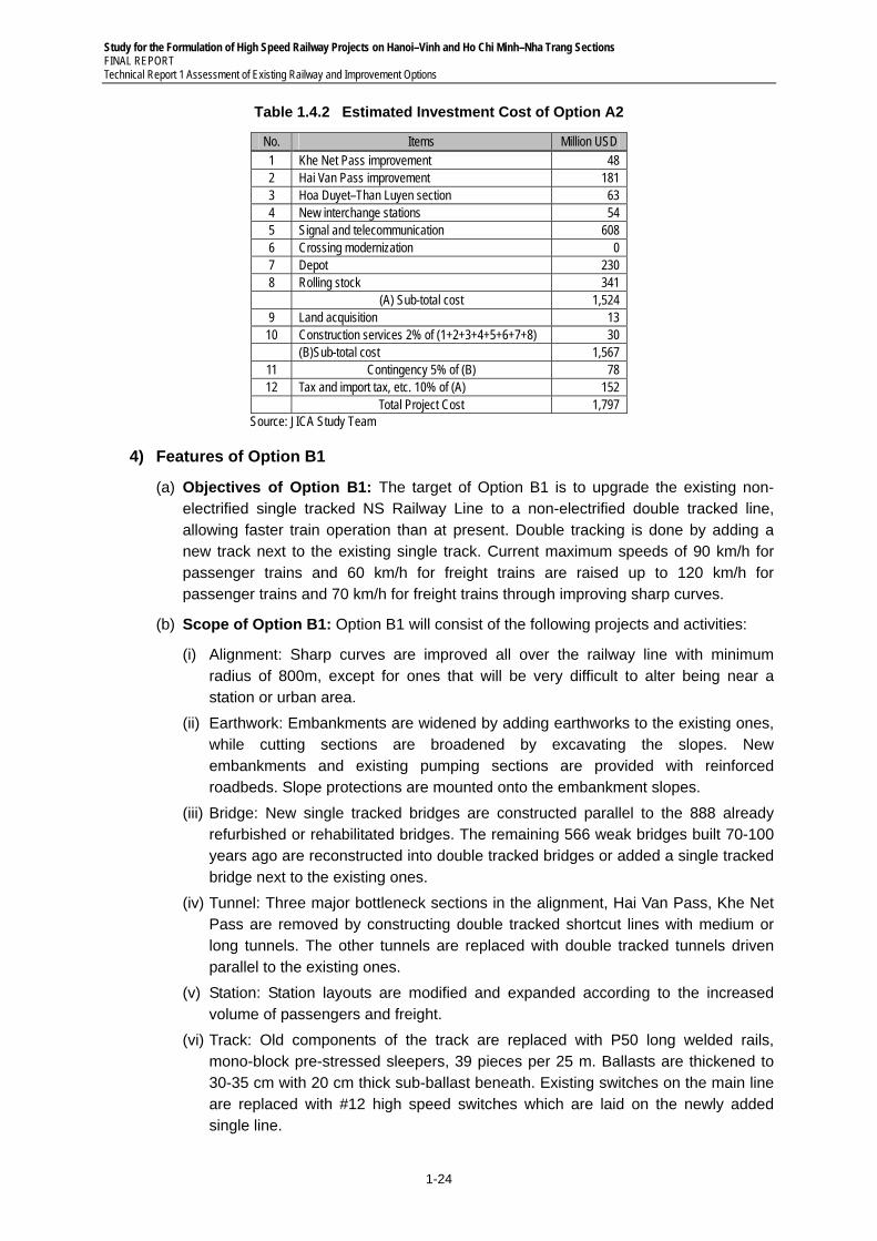
Study for the Formulation of High Speed Railway Projects on Hanoi–Vinh and Ho Chi Minh–Nha Trang Sections FINAL REPORT Technical Report 1 Assessment of Existing Railway and Improvement Options
1-24
Table 1.4.2 Estimated Investment Cost of Option A2
No. Items Million USD 1 Khe Net Pass improvement 48 2 Hai Van Pass improvement 181 3 Hoa Duyet–Than Luyen section 63 4 New interchange stations 54 5 Signal and telecommunication 608 6 Crossing modernization 0 7 Depot 230 8 Rolling stock 341 (A) Sub-total cost 1,524 9 Land acquisition 13
10 Construction services 2% of (1+2+3+4+5+6+7+8) 30 (B)Sub-total cost 1,567
11 Contingency 5% of (B) 78 12 Tax and import tax, etc. 10% of (A) 152
Total Project Cost 1,797 Source: JICA Study Team
4) Features of Option B1
(a) Objectives of Option B1: The target of Option B1 is to upgrade the existing non-electrified single tracked NS Railway Line to a non-electrified double tracked line, allowing faster train operation than at present. Double tracking is done by adding a new track next to the existing single track. Current maximum speeds of 90 km/h for passenger trains and 60 km/h for freight trains are raised up to 120 km/h for passenger trains and 70 km/h for freight trains through improving sharp curves.
(b) Scope of Option B1: Option B1 will consist of the following projects and activities:
(i) Alignment: Sharp curves are improved all over the railway line with minimum radius of 800m, except for ones that will be very difficult to alter being near a station or urban area.
(ii) Earthwork: Embankments are widened by adding earthworks to the existing ones, while cutting sections are broadened by excavating the slopes. New embankments and existing pumping sections are provided with reinforced roadbeds. Slope protections are mounted onto the embankment slopes.
(iii) Bridge: New single tracked bridges are constructed parallel to the 888 already refurbished or rehabilitated bridges. The remaining 566 weak bridges built 70-100 years ago are reconstructed into double tracked bridges or added a single tracked bridge next to the existing ones.
(iv) Tunnel: Three major bottleneck sections in the alignment, Hai Van Pass, Khe Net Pass are removed by constructing double tracked shortcut lines with medium or long tunnels. The other tunnels are replaced with double tracked tunnels driven parallel to the existing ones.
(v) Station: Station layouts are modified and expanded according to the increased volume of passengers and freight.
(vi) Track: Old components of the track are replaced with P50 long welded rails, mono-block pre-stressed sleepers, 39 pieces per 25 m. Ballasts are thickened to 30-35 cm with 20 cm thick sub-ballast beneath. Existing switches on the main line are replaced with #12 high speed switches which are laid on the newly added single line.
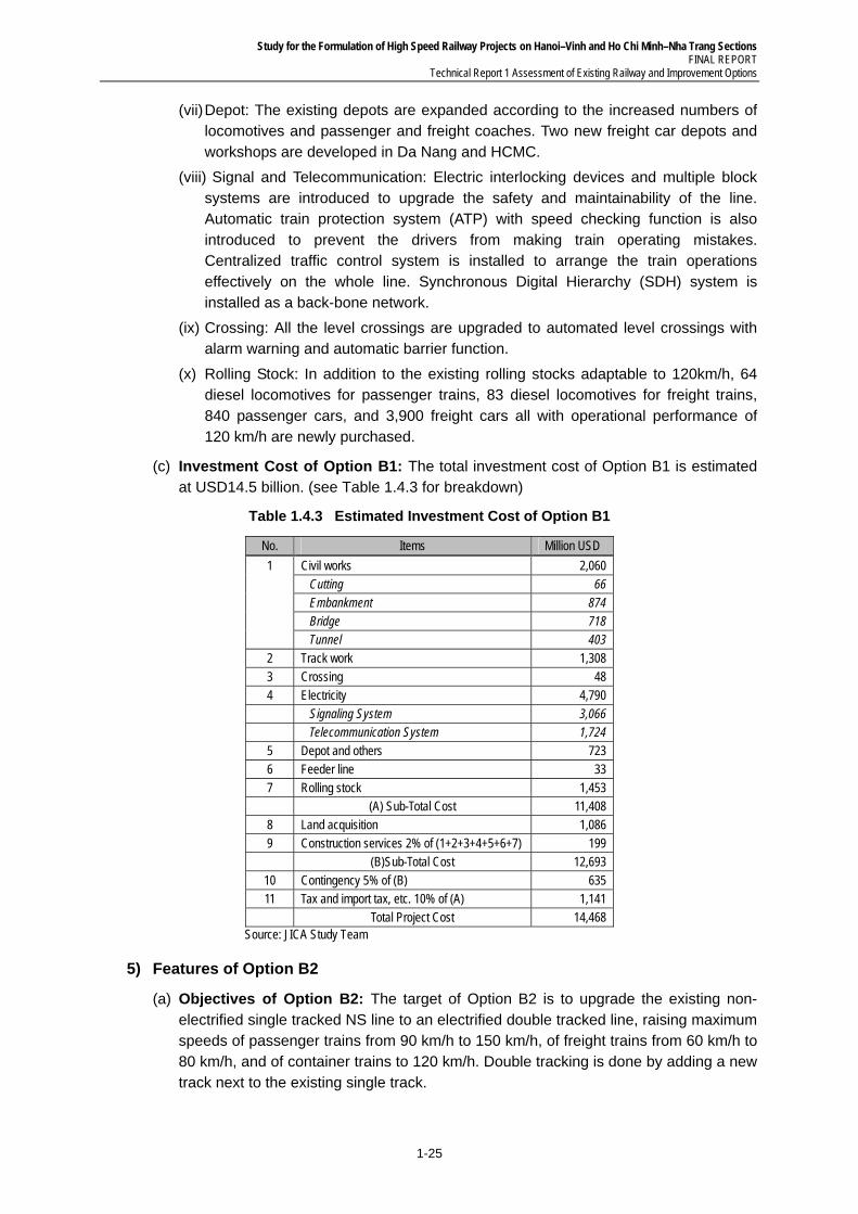
Study for the Formulation of High Speed Railway Projects on Hanoi–Vinh and Ho Chi Minh–Nha Trang Sections FINAL REPORT
Technical Report 1 Assessment of Existing Railway and Improvement Options
1-25
(vii) Depot: The existing depots are expanded according to the increased numbers of locomotives and passenger and freight coaches. Two new freight car depots and workshops are developed in Da Nang and HCMC.
(viii) Signal and Telecommunication: Electric interlocking devices and multiple block systems are introduced to upgrade the safety and maintainability of the line. Automatic train protection system (ATP) with speed checking function is also introduced to prevent the drivers from making train operating mistakes. Centralized traffic control system is installed to arrange the train operations effectively on the whole line. Synchronous Digital Hierarchy (SDH) system is installed as a back-bone network.
(ix) Crossing: All the level crossings are upgraded to automated level crossings with alarm warning and automatic barrier function.
(x) Rolling Stock: In addition to the existing rolling stocks adaptable to 120km/h, 64 diesel locomotives for passenger trains, 83 diesel locomotives for freight trains, 840 passenger cars, and 3,900 freight cars all with operational performance of 120 km/h are newly purchased.
(c) Investment Cost of Option B1: The total investment cost of Option B1 is estimated at USD14.5 billion. (see Table 1.4.3 for breakdown)
Table 1.4.3 Estimated Investment Cost of Option B1
No. Items Million USD
1 Civil works 2,060 Cutting 66 Embankment 874 Bridge 718 Tunnel 403
2 Track work 1,308 3 Crossing 48 4 Electricity 4,790 Signaling System 3,066 Telecommunication System 1,724 5 Depot and others 723 6 Feeder line 33 7 Rolling stock 1,453 (A) Sub-Total Cost 11,408 8 Land acquisition 1,086 9 Construction services 2% of (1+2+3+4+5+6+7) 199 (B)Sub-Total Cost 12,693
10 Contingency 5% of (B) 635 11 Tax and import tax, etc. 10% of (A) 1,141 Total Project Cost 14,468
Source: JICA Study Team
5) Features of Option B2
(a) Objectives of Option B2: The target of Option B2 is to upgrade the existing non-electrified single tracked NS line to an electrified double tracked line, raising maximum speeds of passenger trains from 90 km/h to 150 km/h, of freight trains from 60 km/h to 80 km/h, and of container trains to 120 km/h. Double tracking is done by adding a new track next to the existing single track.
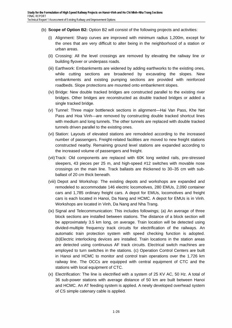
Study for the Formulation of High Speed Railway Projects on Hanoi–Vinh and Ho Chi Minh–Nha Trang Sections FINAL REPORT Technical Report 1 Assessment of Existing Railway and Improvement Options
1-26
(b) Scope of Option B2: Option B2 will consist of the following projects and activities:
(i) Alignment: Sharp curves are improved with minimum radius 1,200m, except for the ones that are very difficult to alter being in the neighborhood of a station or urban areas.
(ii) Crossing: All the level crossings are removed by elevating the railway line or building flyover or underpass roads.
(iii) Earthwork: Embankments are widened by adding earthworks to the existing ones, while cutting sections are broadened by excavating the slopes. New embankments and existing pumping sections are provided with reinforced roadbeds. Slope protections are mounted onto embankment slopes.
(iv) Bridge: New double tracked bridges are constructed parallel to the existing river bridges. Other bridges are reconstructed as double tracked bridges or added a single tracked bridge.
(v) Tunnel: Three major bottleneck sections in alignment—Hai Van Pass, Khe Net Pass and Hoa Vinh—are removed by constructing double tracked shortcut lines with medium and long tunnels. The other tunnels are replaced with double tracked tunnels driven parallel to the existing ones.
(vi) Station: Layouts of elevated stations are remodeled according to the increased number of passengers. Freight-related facilities are moved to new freight stations constructed nearby. Remaining ground level stations are expanded according to the increased volume of passengers and freight.
(vii) Track: Old components are replaced with 60K long welded rails, pre-stressed sleepers, 43 pieces per 25 m, and high-speed #12 switches with movable nose crossings on the main line. Track ballasts are thickened to 30–35 cm with sub-ballast of 20 cm thick beneath.
(viii) Depot and Workshop: The existing depots and workshops are expanded and remodeled to accommodate 146 electric locomotives, 280 EMUs, 2,090 container cars and 1,785 ordinary freight cars. A depot for EMUs, locomotives and freight cars is each located in Hanoi, Da Nang and HCMC. A depot for EMUs is in Vinh. Workshops are located in Vinh, Da Nang and Nha Trang.
(ix) Signal and Telecommunication: This includes followings; (a) An average of three block sections are installed between stations. The distance of a block section will be approximately 3.5 km long, on average. Train location will be detected using divided-multiple frequency track circuits for electrification of the railways. An automatic train protection system with speed checking function is adopted. (b)Electric interlocking devices are installed. Train locations in the station areas are detected using continuous AF track circuits. Electrical switch machines are employed to turn switches in the stations. (c) Operation Control Centers are built in Hanoi and HCMC to monitor and control train operations over the 1,726 km railway line. The OCCs are equipped with central equipment of CTC and the stations with local equipment of CTC.
(x) Electrification: The line is electrified with a system of 25 KV AC, 50 Hz. A total of 36 sub-power stations with average distance of 50 km are built between Hanoi and HCMC. An AT feeding system is applied. A newly developed overhead system of CS simple catenary cable is applied.
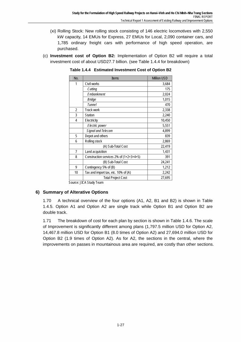
Study for the Formulation of High Speed Railway Projects on Hanoi–Vinh and Ho Chi Minh–Nha Trang Sections FINAL REPORT
Technical Report 1 Assessment of Existing Railway and Improvement Options
1-27
(xi) Rolling Stock: New rolling stock consisting of 146 electric locomotives with 2,550 kW capacity, 14 EMUs for Express, 27 EMUs for Local, 2,090 container cars, and 1,785 ordinary freight cars with performance of high speed operation, are purchased.
(c) Investment cost of Option B2: Implementation of Option B2 will require a total investment cost of about USD27.7 billion. (see Table 1.4.4 for breakdown)
Table 1.4.4 Estimated Investment Cost of Option B2
No. Items Million USD
1 Civil works 3,684 Cutting 175 Embankment 2,024 Bridge 1,015 Tunnel 470
2 Track work 2,338 3 Station 2,240 4 Electricity 10,450 Electric power 5,551 Signal and Telecom 4,899 5 Depot and others 839 6 Rolling stock 2,869 (A) Sub-Total Cost 22,419 7 Land acquisition 1,431 8 Construction services 2% of (1+2+3+4+5) 391 (B) Sub-Total Cost 24,241 9 Contingency 5% of (B) 1,212
10 Tax and import tax, etc. 10% of (A) 2,242 Total Project Cost 27,695
Source: JICA Study Team
6) Summary of Alterative Options
1.70 A technical overview of the four options (A1, A2, B1 and B2) is shown in Table 1.4.5. Option A1 and Option A2 are single track while Option B1 and Option B2 are double track.
1.71 The breakdown of cost for each plan by section is shown in Table 1.4.6. The scale of Improvement is significantly different among plans (1,797.5 million USD for Option A2, 14,467.8 million USD for Option B1 (8.0 times of Option A2) and 27,694.0 million USD for Option B2 (1.9 times of Option A2). As for A2, the sections in the central, where the improvements on passes in mountainous area are required, are costly than other sections.
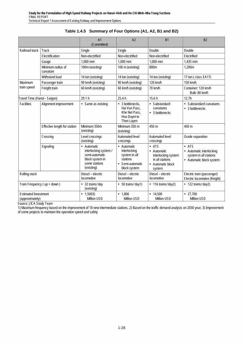
Study for the Formulation of High Speed Railway Projects on Hanoi–Vinh and Ho Chi Minh–Nha Trang Sections FINAL REPORT Technical Report 1 Assessment of Existing Railway and Improvement Options
1-28
Table 1.4.5 Summary of Four Options (A1, A2, B1 and B2)
A1 (Committed)
A2 B1 B2
Railroad track Track Single Single Double Double
Electrification Non-electrified Non-electrified Non-electrified Electrified
Gauge 1,000 mm 1,000 mm 1,000 mm 1,435 mm
Minimum radius of curvature
100m (existing) 100 m (existing) 800m 1,200m
Withstand load 14 ton (existing) 14 ton (existing) 14 ton (existing) 17 ton ( class EA17)
Maximum train speed
Passenger train 90 km/h (existing) 90 km/h (existing) 120 km/h 150 km/h
Freight train 60 km/h (existing) 60 km/h (existing) 70 km/h Container: 120 km/h Bulk: 80 km/h
Travel Time (Hanoi - Saigon) 29.1 h 25.4 h 15.6 h 12.7h
Facilities Alignment improvement Same as existing 3 bottlenecks, Hai Van Pass, Khe Net Pass, Hoa Duyet to Thon Luyen
Substandard curvatures
3 bottlenecks
Substandard curvatures 3 bottlenecks
Effective length for station Minimum 350m (existing)
Minimum 350 m (existing)
450 m 450 m
Crossing Level crossings (existing)
Automated level crossings
Automated level crossings
Grade separation
Signaling Automatic interlocking system / semi-automatic block system in some stations (existing)
Automatic interlocking system in all stations
Semi-automatic block system
ATS Automatic
interlocking system in all stations
Automatic block system
ATS Automatic interlocking
system in all stations Automatic block system
Rolling stock Diesel – electric locomotive
Diesel – electric locomotive
Diesel – electric locomotive
Electric train (passenger) Electric locomotive (freight)
Train Frequency ( up + down ) 32 trains/ day (existing)
50 trains/ day1) 116 trains/ day2) 122 trains/ day2)
Estimated Investment (approximately)
1,5003) Million USD
1,800 Million USD
14,500 Million USD
27,700 Million USD
Source: JICA Study Team 1) Maximum frequency based on the improvement of 18 new intermediate stations, 2) Based on the traffic demand analysis on 2030 year, 3) Improvement of some projects to maintain the operation speed and safety
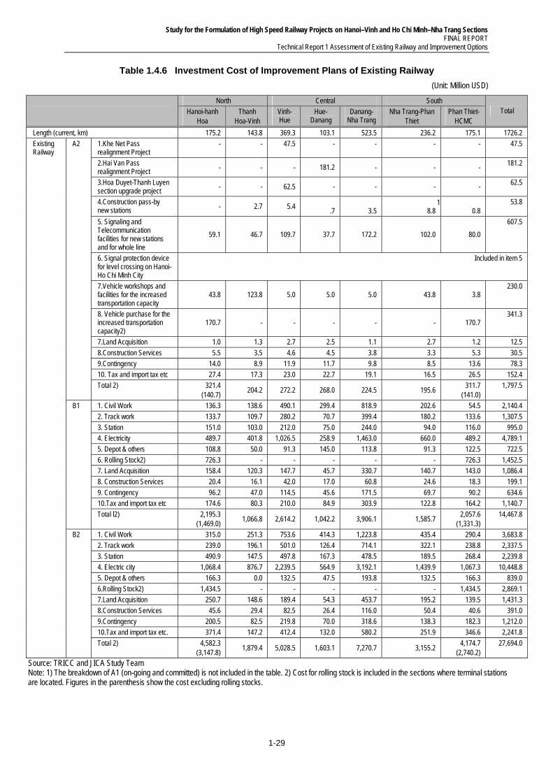
Study for the Formulation of High Speed Railway Projects on Hanoi–Vinh and Ho Chi Minh–Nha Trang Sections FINAL REPORT
Technical Report 1 Assessment of Existing Railway and Improvement Options
1-29
Table 1.4.6 Investment Cost of Improvement Plans of Existing Railway
(Unit: Million USD)
North Central South
Total Hanoi-hanh Hoa
Thanh Hoa-Vinh
Vinh-Hue
Hue-Danang
Danang-Nha Trang
Nha Trang-Phan Thiet
Phan Thiet- HCMC
Length (current, km) 175.2 143.8 369.3 103.1 523.5 236.2 175.1 1726.2
Existing Railway
A2 1.Khe Net Pass realignment Project
- - 47.5 - - - - 47.5
2.Hai Van Pass realignment Project - - - 181.2 - - -
181.2
3.Hoa Duyet-Thanh Luyen section upgrade project
- - 62.5 - - - - 62.5
4.Construction pass-by new stations - 2.7 5.4
.7 3.5 1
8.8 0.8 53.8
5. Signaling and Telecommunication facilities for new stations and for whole line
59.1 46.7 109.7 37.7 172.2 102.0 80.0
607.5
6. Signal protection device for level crossing on Hanoi-Ho Chi Minh City
Included in item 5
7.Vehicle workshops and facilities for the increased transportation capacity
43.8 123.8 5.0 5.0 5.0 43.8 3.8 230.0
8. Vehicle purchase for the increased transportation capacity2)
170.7 - - - - - 170.7 341.3
7.Land Acquisition 1.0 1.3 2.7 2.5 1.1 2.7 1.2 12.5
8.Construction Services 5.5 3.5 4.6 4.5 3.8 3.3 5.3 30.5
9.Contingency 14.0 8.9 11.9 11.7 9.8 8.5 13.6 78.3
10. Tax and import tax etc 27.4 17.3 23.0 22.7 19.1 16.5 26.5 152.4
Total 2) 321.4 (140.7)
204.2 272.2 268.0 224.5 195.6 311.7
(141.0) 1,797.5
B1 1. Civil Work 136.3 138.6 490.1 299.4 818.9 202.6 54.5 2,140.4
2. Track work 133.7 109.7 280.2 70.7 399.4 180.2 133.6 1,307.5
3. Station 151.0 103.0 212.0 75.0 244.0 94.0 116.0 995.0
4. Electricity 489.7 401.8 1,026.5 258.9 1,463.0 660.0 489.2 4,789.1
5. Depot & others 108.8 50.0 91.3 145.0 113.8 91.3 122.5 722.5
6. Rolling Stock2) 726.3 - - - - - 726.3 1,452.5
7. Land Acquisition 158.4 120.3 147.7 45.7 330.7 140.7 143.0 1,086.4
8. Construction Services 20.4 16.1 42.0 17.0 60.8 24.6 18.3 199.1
9. Contingency 96.2 47.0 114.5 45.6 171.5 69.7 90.2 634.6
10.Tax and import tax etc 174.6 80.3 210.0 84.9 303.9 122.8 164.2 1,140.7
Total l2) 2,195.3 (1,469.0)
1,066.8 2,614.2 1,042.2 3,906.1 1,585.7 2,057.6
(1,331.3) 14,467.8
B2 1. Civil Work 315.0 251.3 753.6 414.3 1,223.8 435.4 290.4 3,683.8
2. Track work 239.0 196.1 501.0 126.4 714.1 322.1 238.8 2,337.5
3. Station 490.9 147.5 497.8 167.3 478.5 189.5 268.4 2,239.8
4. Electric city 1,068.4 876.7 2,239.5 564.9 3,192.1 1,439.9 1,067.3 10,448.8
5. Depot & others 166.3 0.0 132.5 47.5 193.8 132.5 166.3 839.0
6.Rolling Stock2) 1,434.5 - - - - - 1,434.5 2,869.1
7.Land Acquisition 250.7 148.6 189.4 54.3 453.7 195.2 139.5 1,431.3
8.Construction Services 45.6 29.4 82.5 26.4 116.0 50.4 40.6 391.0
9.Contingency 200.5 82.5 219.8 70.0 318.6 138.3 182.3 1,212.0
10.Tax and import tax etc. 371.4 147.2 412.4 132.0 580.2 251.9 346.6 2,241.8
Total 2) 4,582.3 (3,147.8)
1,879.4 5,028.5 1,603.1 7,270.7 3,155.2 4,174.7
(2,740.2) 27,694.0
Source: TRICC and JICA Study Team Note: 1) The breakdown of A1 (on-going and committed) is not included in the table. 2) Cost for rolling stock is included in the sections where terminal stations are located. Figures in the parenthesis show the cost excluding rolling stocks.
Study for the Formulation of High Speed Railway Projects on Hanoi–Vinh and Ho Chi Minh–Nha Trang Sections FINAL REPORT Technical Report 1 Assessment of Existing Railway and Improvement Options
1-30
1.72 Brief evaluation of each option excluding A1 (consisting of committed and ongoing projects) is as follows;
(a) Option A2: The significant time savings is expected to be brought mainly by realignment of Hai Van Pass section (about 1 hour) and construction of 18 siding stations (about 2 and a half hours) as well as the operating cost savings resulting from the mode transfer. It is, therefore, highly recommendable to realize Hai Van Pass improvement and 18 new siding stations as soon as possible. The two projects along with the ongoing bridge improvement project of Option A1 and other improvement projects involved in Option A2 will enable to increase the operational capacity of the NS line from at present 32 up and down trains a day up to maximum 50 trains a day. There will be 13 pairs of through express train instead of current 5 pairs when A2 completed. This will upturn at present losing market share both in passenger and freight transportation.
(b) Option B1: The amount of investment for B1 is too enormous to implement for the entire 1,726 km at once. Stage implementation, therefore, has to be considered. Priority should be given to those sections whose traffic densities are coming close to their maximum operational capacities. Another important factor to be taken into account is that double tracking requires huge amount of land acquisition and relocation of numerous households. According to the calculations done by TRICC and the Study Team, roughly 10 km2 of land acquisition will be needed while over 10,000 households have to be resettled. It is crucial to secure understanding and cooperation of the citizens before starting the project. Environmental Impact Assessment, therefore, is an essential part of the process. In the course of EIA the problem of illegally occupied areas within the each 15 m wide Right of Way range will inevitably arise. A definite decision making on how to resolve the problem would be necessary before implementation.
1.73 Option B1 will shorten the travel time between Hanoi and HCMC from current 29.5 hours by SE3 to 15.5 hours by the fastest trains when B1 completed. Frequencies of both passenger train and freight train are also improved. Current 7–13 pairs of passenger train increase up to 10–20 pairs while from current 5–6 pairs to 31 –38 pairs for freight train.
(c) Option B2: The biggest advantage Option B2 brings is that all the level crossings are removed and level separated all along the NS line. Structures in urban areas are elevated high from the ground level which means far less railway accidents than at present. Of the 466 railway accidents that took place along the North South line in 2010, 451 were objective accidents. It is expected most of those accidents will disappear when B2 is completed. Alleviating effects on road traffic accidents brought by modal transfer from road to railway should also be taken into account. Evaluation of these effects would require further studies to figure out the method of measurement.
1.74 As for social considerations, land acquisition of over 20 km2 will be needed while nearly 20,000 households have to be resettled.
1.75 The shortest travel time from Hanoi to HCMC is 12.7 hours by the fastest express train when Option B2 completed. Frequencies increase to 10–21 pairs of passenger train, to 31-40 pairs of freight train.
Study for the Formulation of High Speed Railway Projects on Hanoi–Vinh and Ho Chi Minh–Nha Trang Sections FINAL REPORT
Technical Report 1 Assessment of Existing Railway and Improvement Options
2-1
2 OPERATION CONTROL
2.1 Operation Control
2.1 Safety is the most important requirement for train operation, which is largely governed by signals, platform equipment, automatic crossing operation and design of structures. For railways, the next most important factor after safety is reliability of transport. What contributes to this mission is operation control.
2.2 Delays in daily train operation are often caused by changes in meteorological conditions, accidents at crossings and failures of signals, rolling stock, tracks and other equipment. The prompt and correct respond to and deal with such situations is train-dispatching services. A series of the deeds to issue and support commands and instructions of train dispatch are generally called operation control.
2.2 Phased Development of Operation Control
1) Initial Phase
2.3 At the initial phase, railway operators organize a train dispatch center and install direct telephones connected to passenger and signal stations, train crew depots (train operation depots and conductor depots), rolling stock depots, track maintenance depots, signal depots, telecommunication depots and other field organizations, through which the center collect reports on train operation status from station masters on duty and signal men for operation adjustment and issuance of commands and instructions to recover normalcy.
2) Phase 2
2.4 Railway operators additionally install an indicator to show the train at stop on each track at the train dispatch center, or a system to indicate the train number on each track at the track display board. In Japan, this is implemented by utilizing track circuit conditions without relying on the reports on train operation status, thereby facilitating quick assessment of train delays and expediting action for operation adjustment.
3) Phase 3
2.5 Railway operators incorporate the function of a signal control device into the above indicator to introduce the centralized traffic control (CTC) system, thereby enabling collective train control at the train dispatch center. This is to centralize the signal handling implemented at stations in the past for the purpose of operation control. As trains, hitherto controlled by signalmen at stations based on the commands obtained through the train dispatch telephone, are now directly controlled by the train dispatcher, the system realizes quick operation adjustment while significantly cutting manpower.
2.6 Although funds invested into equipment temporarily increase, its economic effect due to the efficient staff assignment is significant. Railway operators have introduced the system, therefore, to improve the efficiency of management.
4) Phase 4
2.7 When the frequency of train operation has increased as a result of double-tracking, railway operators introduce the automatic route control (ARC) system, while adopting the standard station track layout simultaneously. Under this system, routes are automatically
Study for the Formulation of High Speed Railway Projects on Hanoi–Vinh and Ho Chi Minh–Nha Trang Sections FINAL REPORT Technical Report 1 Assessment of Existing Railway and Improvement Options
2-2
controlled at midway stations other than terminal stations or large-scale stations (with more than four departure/arrival tracks). Without increasing the number of staff members, more trains can be operated as a result.
2.8 As the introduction of ARC requires standardization of train operation patterns, however, the system was adopted only for Tokaido Shinkansen with simple operations before it was extended to Okayama. The hourly operation of three Hikari trains and six Kodama trains were controlled in the past by the ARC system. However, the ARC system does not suit the operation control of freight trains studded with promiscuous operation patterns.
5) Phase 5
2.9 As train types diversify (with operation patterns increased), computers are introduced, in case the ARC system does not cope with). Computers implement programmed route control (PRC) to facilitate the work of statistics on train delays and train operation.
2.10 The introduction of CTC with PRC relieved the train dispatchers from signal handling, which was previously a principal part of train dispatch services, and allowed them to devote themselves to the original work of operation adjustment. The computerized operation control system can significantly change the cost of equipment depending on the development concept of users.
2.11 As mentioned above, operation control has progressed and been renewed as the frequency of train operation increases and operation facilities are improved.
Study for the Formulation of High Speed Railway Projects on Hanoi–Vinh and Ho Chi Minh–Nha Trang Sections FINAL REPORT
Technical Report 1 Assessment of Existing Railway and Improvement Options
2-3
2.3 Present Status of the Operation Control of Vietnam Railways
2.12 The present status of the technology division of VR is as follows.
2.13 Operation control is still at an initial stage in that train operation adjustment is implemented by means of train dispatching telephones alone without using textual dispatching facilities such as facsimiles or telegraphic machines.
2.14 The Ha Noi–Saigon section (1,726.2 km) is divided into three segments, each under an independent dispatching office for operation control. A dispatching center (an adjusting room) was set to perform adjustment between the three dispatching offices that are in charge of the following segments.
(a) Hanoi–Dong Hoi Segment (58 sections): Ha Noi train dispatching office
(b) Dong–Dieu Tri Segment (55 sections): Da Nang dispatching office
(c) Dieu Tri–Saigon segment (53 sections): Saigon dispatching office
2.15 To perform transport businesses, VR has three divisions for general affairs, planning and statistics, and professional technology in addition to an adjustment room and three train-dispatching offices. It has 163 members in total including about 30 at three divisions and 82, 26 and 24 members, respectively, at the Hanoi, Da Nang and Saigon dispatching offices (82 members at the Hanoi dispatching office include those for train operation adjustment and dispatching).
2.16 The assignments of the planning and statistics divisions: the records of passenger and freight transport, car-kilometers and revenue
2.17 The assignments of the technology division: the transport planning, technological rules and control of dispatching
2.18 Planned train operation diagrams are posted on the walls of dispatching offices. Train operation diagrams for the day are manually created. Hand-written diagrams to record actual train operation are kept for five years.
2.4 Operation Control Recommended for the Improved Options of Existing Lines
2.19 The preparation and facilities stated in Phase 2 are considered sufficient for the control of number of trains (A-1) as current frequency and that is envisaged in the scenario (A-2).
2.20 For the options (B-1) and (B-2), the operation control at the phase 3 seems to be sufficient. Introduction of ARC described for the phase 4 is little effective when freight trains are operated. For the operation of approximately 150 trains, PRC expected at the phase 5 is premature, in view of the time of the completion of CTC introduction.
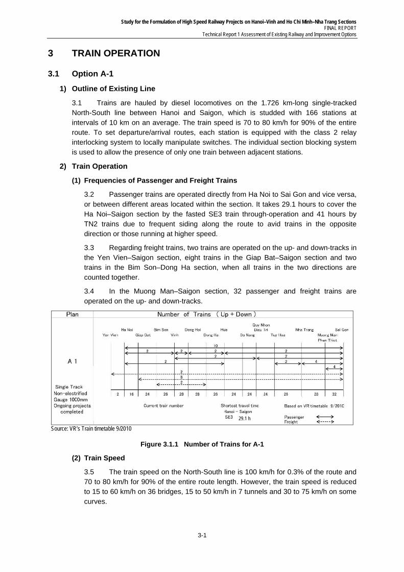
Study for the Formulation of High Speed Railway Projects on Hanoi–Vinh and Ho Chi Minh–Nha Trang Sections FINAL REPORT
Technical Report 1 Assessment of Existing Railway and Improvement Options
3-1
3 TRAIN OPERATION
3.1 Option A-1
1) Outline of Existing Line
3.1 Trains are hauled by diesel locomotives on the 1.726 km-long single-tracked North-South line between Hanoi and Saigon, which is studded with 166 stations at intervals of 10 km on an average. The train speed is 70 to 80 km/h for 90% of the entire route. To set departure/arrival routes, each station is equipped with the class 2 relay interlocking system to locally manipulate switches. The individual section blocking system is used to allow the presence of only one train between adjacent stations.
2) Train Operation
(1) Frequencies of Passenger and Freight Trains
3.2 Passenger trains are operated directly from Ha Noi to Sai Gon and vice versa, or between different areas located within the section. It takes 29.1 hours to cover the Ha Noi–Saigon section by the fasted SE3 train through-operation and 41 hours by TN2 trains due to frequent siding along the route to avid trains in the opposite direction or those running at higher speed.
3.3 Regarding freight trains, two trains are operated on the up- and down-tracks in the Yen Vien–Saigon section, eight trains in the Giap Bat–Saigon section and two trains in the Bim Son–Dong Ha section, when all trains in the two directions are counted together.
3.4 In the Muong Man–Saigon section, 32 passenger and freight trains are operated on the up- and down-tracks.
29.1 h
Source: VR’s Train timetable 9/2010
Figure 3.1.1 Number of Trains for A-1
(2) Train Speed
3.5 The train speed on the North-South line is 100 km/h for 0.3% of the route and 70 to 80 km/h for 90% of the entire route length. However, the train speed is reduced to 15 to 60 km/h on 36 bridges, 15 to 50 km/h in 7 tunnels and 30 to 75 km/h on some curves.
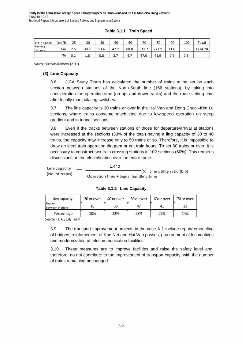
Study for the Formulation of High Speed Railway Projects on Hanoi–Vinh and Ho Chi Minh–Nha Trang Sections FINAL REPORT Technical Report 1 Assessment of Existing Railway and Improvement Options
3-2
Table 3.1.1 Train Speed
Train speed km/h 25 30 40 50 60 70 80 90 100 TotalRunning
distance Km 2.5 30.7 13.4 47.2 80.8 811.2 721.9 11.0 5.9 1724.78
% 0.1 1.8 0.8 2.7 4.7 47.0 41.9 0.6 0.3
Source: Vietnam Railways (2011)
(3) Line Capacity
3.6 JICA Study Team has calculated the number of trains to be set on each section between stations of the North-South line (166 stations), by taking into consideration the operation time (on up- and down-tracks) and the route setting time after locally manipulating switches.
3.7 The line capacity is 30 trains or over in the Hai Van and Dong Chuoi–Kim Lu sections, where trains consume much time due to low-speed operation on steep gradient and in tunnel sections.
3.8 Even if the tracks between stations or those for departure/arrival at stations were increased at the sections (33% of the total) having a ling capacity of 30 to 40 trains, the capacity may increase only to 50 trains or so. Therefore, it is impossible to draw an ideal train operation diagram or cut train hours. To set 60 trains or over, it is necessary to construct two-train crossing stations in 102 sections (60%). This requires discussions on the electrification over the entire route.
1.440 Line utility ratio (0.6)
Operation time + Signal handling time
Line capacity
(No. of trains)
Table 3.1.2 Line Capacity
Line capacity 30 or over 40 or over 50 or over 60 or over 70 or overSection
between stations 16 39 47 41 23
Percentage 10% 23% 28% 25% 14%
Source: JICA Study Team
3.9 The transport improvement projects in the case A-1 include repair/remodeling of bridges, reinforcement of Khe Net and Hai Van passes, procurement of locomotives and modernization of telecommunication facilities.
3.10 These measures are to improve facilities and raise the safety level and. therefore, do not contribute to the improvement of transport capacity, with the number of trains remaining unchanged.
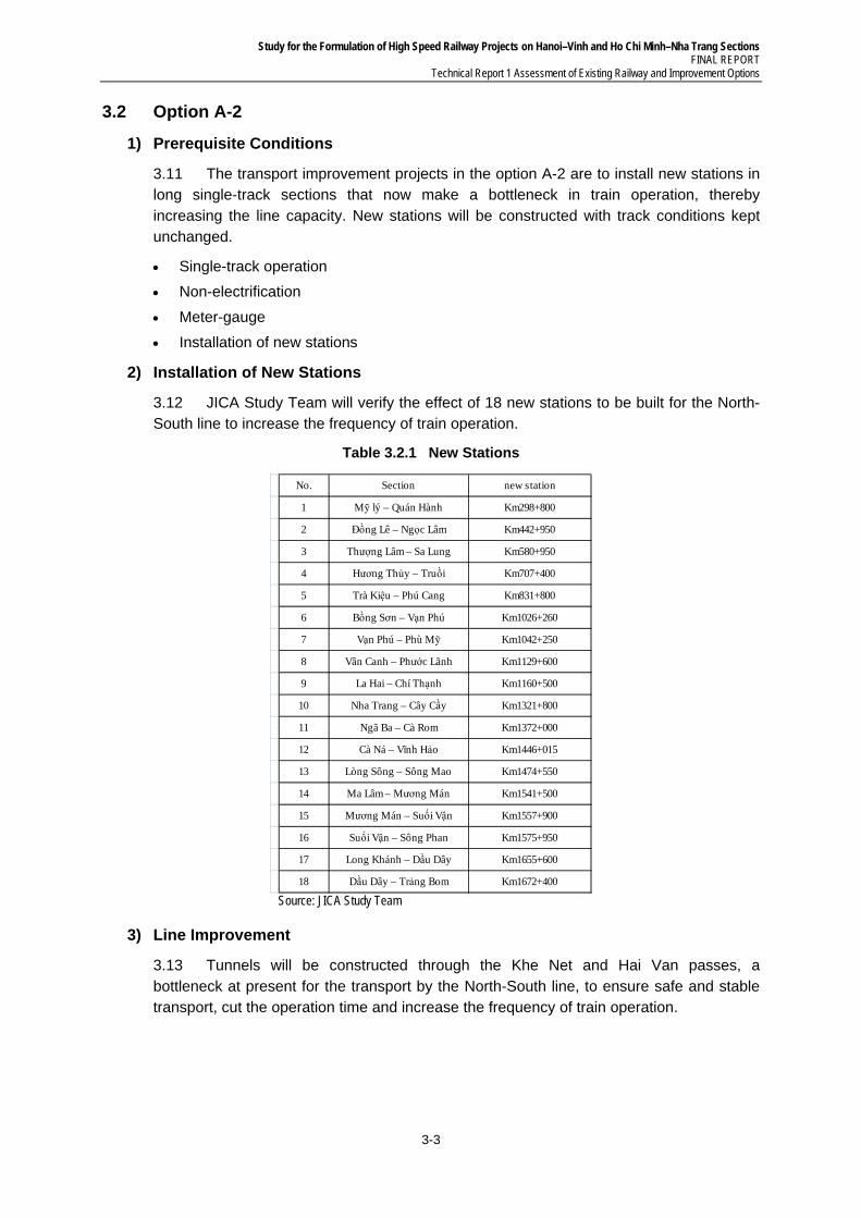
Study for the Formulation of High Speed Railway Projects on Hanoi–Vinh and Ho Chi Minh–Nha Trang Sections FINAL REPORT
Technical Report 1 Assessment of Existing Railway and Improvement Options
3-3
3.2 Option A-2
1) Prerequisite Conditions
3.11 The transport improvement projects in the option A-2 are to install new stations in long single-track sections that now make a bottleneck in train operation, thereby increasing the line capacity. New stations will be constructed with track conditions kept unchanged.
Single-track operation
Non-electrification
Meter-gauge
Installation of new stations
2) Installation of New Stations
3.12 JICA Study Team will verify the effect of 18 new stations to be built for the North-South line to increase the frequency of train operation.
Table 3.2.1 New Stations
No. Section new station
1 Mỹ lý – Quán Hành Km298+800
2 Đồng Lê – Ngọc Lâm Km442+950
3 Thượng Lâm – Sa Lung Km580+950
4 Hương Thủy – Truồi Km707+400
5 Trà Kiệu – Phú Cang Km831+800
6 Bồng Sơn – Vạn Phú Km1026+260
7 Vạn Phú – Phù Mỹ Km1042+250
8 Vân Canh – Phước Lãnh Km1129+600
9 La Hai – Chí Thạnh Km1160+500
10 Nha Trang – Cây Cầy Km1321+800
11 Ngã Ba – Cà Rom Km1372+000
12 Cà Ná – Vĩnh Hảo Km1446+015
13 Lòng Sông – Sông Mao Km1474+550
14 Ma Lâm – Mương Mán Km1541+500
15 Mương Mán – Suối Vận Km1557+900
16 Suối Vận – Sông Phan Km1575+950
17 Long Khánh – Dầu Dây Km1655+600
18 Dầu Dây – Trảng Bom Km1672+400 Source: JICA Study Team
3) Line Improvement
3.13 Tunnels will be constructed through the Khe Net and Hai Van passes, a bottleneck at present for the transport by the North-South line, to ensure safe and stable transport, cut the operation time and increase the frequency of train operation.
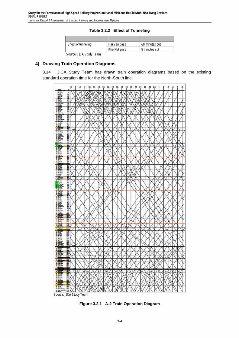
Study for the Formulation of High Speed Railway Projects on Hanoi–Vinh and Ho Chi Minh–Nha Trang Sections FINAL REPORT Technical Report 1 Assessment of Existing Railway and Improvement Options
3-4
Table 3.2.2 Effect of Tunneling
Effect of tunneling Hai Van pass 60 minutes cut Khe Net pass 8 minutes cut
Source: JICA Study Team.
4) Drawing Train Operation Diagrams
3.14 JICA Study Team has drawn train operation diagrams based on the existing standard operation time for the North-South line.
Source: JICA Study Team
Figure 3.2.1 A-2 Train Operation Diagram
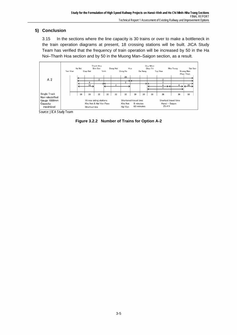
Study for the Formulation of High Speed Railway Projects on Hanoi–Vinh and Ho Chi Minh–Nha Trang Sections FINAL REPORT
Technical Report 1 Assessment of Existing Railway and Improvement Options
3-5
5) Conclusion
3.15 In the sections where the line capacity is 30 trains or over to make a bottleneck in the train operation diagrams at present, 18 crossing stations will be built. JICA Study Team has verified that the frequency of train operation will be increased by 50 in the Ha Noi–Thanh Hoa section and by 50 in the Muong Man–Saigon section, as a result.
Source: JICA Study Team
Figure 3.2.2 Number of Trains for Option A-2
25.4 h 60 minutes
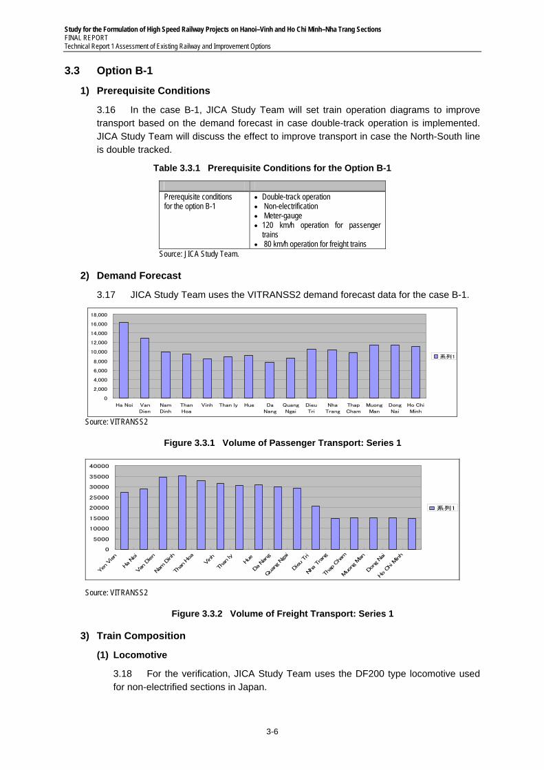
Study for the Formulation of High Speed Railway Projects on Hanoi–Vinh and Ho Chi Minh–Nha Trang Sections FINAL REPORT Technical Report 1 Assessment of Existing Railway and Improvement Options
3-6
3.3 Option B-1
1) Prerequisite Conditions
3.16 In the case B-1, JICA Study Team will set train operation diagrams to improve transport based on the demand forecast in case double-track operation is implemented. JICA Study Team will discuss the effect to improve transport in case the North-South line is double tracked.
Table 3.3.1 Prerequisite Conditions for the Option B-1
Prerequisite conditions for the option B-1
Double-track operation Non-electrification Meter-gauge 120 km/h operation for passenger
trains 80 km/h operation for freight trains
Source: JICA Study Team.
2) Demand Forecast
3.17 JICA Study Team uses the VITRANSS2 demand forecast data for the case B-1.
0
2,000
4,000
6,000
8,000
10,000
12,000
14,000
16,000
18,000
Ha Noi VanDien
NamDinh
ThanHoa
Vinh Than ly Hue DaNang
QuangNgai
DieuTri
NhaTrang
ThapCham
MuongMan
DongNai
Ho ChiMinh
系列1
Source: VITRANSS2
Figure 3.3.1 Volume of Passenger Transport: Series 1
0
5000
10000
15000
20000
25000
30000
35000
40000
Yen Vien
Ha Noi
Van Dien
Nam
Dinh
Than Hoa
Vinh
Than ly
Hue
Da Nang
Quang Ngai
Dieu Tri
Nha Trang
Thap Cham
Muong M
an
Dong Nai
Ho Chi M
inh
系列1
Source: VITRANSS2
Figure 3.3.2 Volume of Freight Transport: Series 1
3) Train Composition
(1) Locomotive
3.18 For the verification, JICA Study Team uses the DF200 type locomotive used for non-electrified sections in Japan.
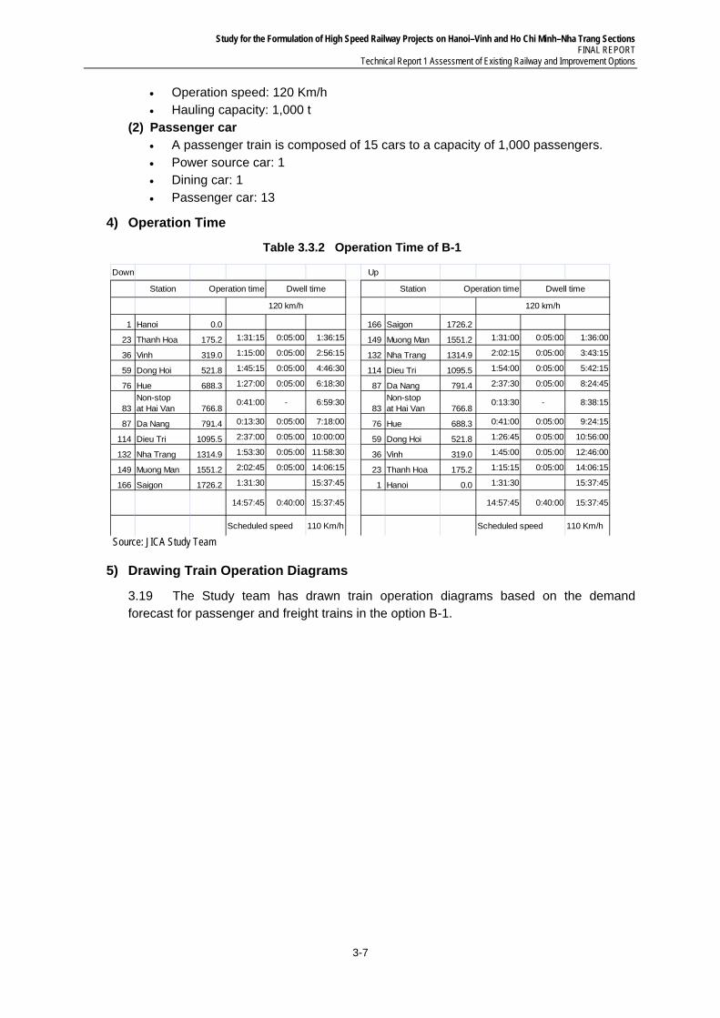
Study for the Formulation of High Speed Railway Projects on Hanoi–Vinh and Ho Chi Minh–Nha Trang Sections FINAL REPORT
Technical Report 1 Assessment of Existing Railway and Improvement Options
3-7
Operation speed: 120 Km/h Hauling capacity: 1,000 t
(2) Passenger car A passenger train is composed of 15 cars to a capacity of 1,000 passengers. Power source car: 1 Dining car: 1 Passenger car: 13
4) Operation Time
Table 3.3.2 Operation Time of B-1
Down Up
Station Operation time Station Operation time
1 Hanoi 0.0 166 Saigon 1726.2
23 Thanh Hoa 175.2 1:31:15 0:05:00 1:36:15 149 Muong Man 1551.2 1:31:00 0:05:00 1:36:00
36 Vinh 319.0 1:15:00 0:05:00 2:56:15 132 Nha Trang 1314.9 2:02:15 0:05:00 3:43:15
59 Dong Hoi 521.8 1:45:15 0:05:00 4:46:30 114 Dieu Tri 1095.5 1:54:00 0:05:00 5:42:15
76 Hue 688.3 1:27:00 0:05:00 6:18:30 87 Da Nang 791.4 2:37:30 0:05:00 8:24:45
83Non-stop at Hai Van 766.8
0:41:00 - 6:59:3083
Non-stop at Hai Van 766.8
0:13:30 - 8:38:15
87 Da Nang 791.4 0:13:30 0:05:00 7:18:00 76 Hue 688.3 0:41:00 0:05:00 9:24:15
114 Dieu Tri 1095.5 2:37:00 0:05:00 10:00:00 59 Dong Hoi 521.8 1:26:45 0:05:00 10:56:00
132 Nha Trang 1314.9 1:53:30 0:05:00 11:58:30 36 Vinh 319.0 1:45:00 0:05:00 12:46:00
149 Muong Man 1551.2 2:02:45 0:05:00 14:06:15 23 Thanh Hoa 175.2 1:15:15 0:05:00 14:06:15
166 Saigon 1726.2 1:31:30 15:37:45 1 Hanoi 0.0 1:31:30 15:37:45
14:57:45 0:40:00 15:37:45 14:57:45 0:40:00 15:37:45
Scheduled speed 110 Km/h Scheduled speed 110 Km/h
Dwell time Dwell time
120 km/h 120 km/h
Source: JICA Study Team
5) Drawing Train Operation Diagrams
3.19 The Study team has drawn train operation diagrams based on the demand forecast for passenger and freight trains in the option B-1.
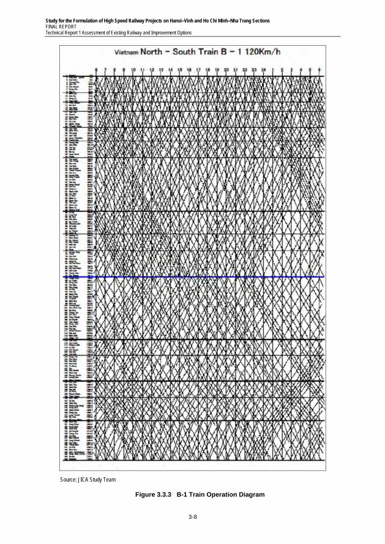
Study for the Formulation of High Speed Railway Projects on Hanoi–Vinh and Ho Chi Minh–Nha Trang Sections FINAL REPORT Technical Report 1 Assessment of Existing Railway and Improvement Options
3-8
Source: JICA Study Team
Figure 3.3.3 B-1 Train Operation Diagram
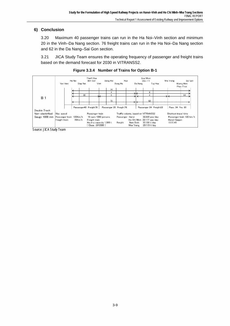
Study for the Formulation of High Speed Railway Projects on Hanoi–Vinh and Ho Chi Minh–Nha Trang Sections FINAL REPORT
Technical Report 1 Assessment of Existing Railway and Improvement Options
3-9
6) Conclusion
3.20 Maximum 40 passenger trains can run in the Ha Noi–Vinh section and minimum 20 in the Vinh–Da Nang section. 76 freight trains can run in the Ha Noi–Da Nang section and 62 in the Da Nang–Sai Gon section.
3.21 JICA Study Team ensures the operating frequency of passenger and freight trains based on the demand forecast for 2030 in VITRANSS2.
Figure 3.3.4 Number of Trains for Option B-1
Source: JICA Study Team
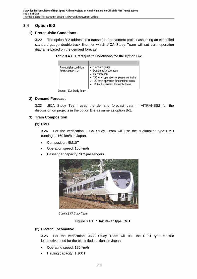
Study for the Formulation of High Speed Railway Projects on Hanoi–Vinh and Ho Chi Minh–Nha Trang Sections FINAL REPORT Technical Report 1 Assessment of Existing Railway and Improvement Options
3-10
3.4 Option B-2
1) Prerequisite Conditions
3.22 The option B-2 addresses a transport improvement project assuming an electrified standard-gauge double-track line, for which JICA Study Team will set train operation diagrams based on the demand forecast.
Table 3.4.1 Prerequisite Conditions for the Option B-2
Prerequisite conditions for the option B-2
Standard gauge Double-track operation Electrification 150 km/h operation for passenger trains 120 km/h operation for container trains 80 km/h operation for freight trains
Source: JICA Study Team
2) Demand Forecast
3.23 JICA Study Team uses the demand forecast data in VITRANSS2 for the discussion on projects in the option B-2 as same as option B-1.
3) Train Composition
(1) EMU
3.24 For the verification, JICA Study Team will use the “Hakutaka” type EMU running at 160 km/h in Japan.
Composition: 5M10T
Operation speed: 150 km/h
Passenger capacity: 962 passengers
Source: JICA Study Team
Figure 3.4.1 “Hakutaka” type EMU
(2) Electric Locomotive
3.25 For the verification, JICA Study Team will use the EF81 type electric locomotive used for the electrified sections in Japan
Operating speed: 120 km/h
Hauling capacity: 1,100 t
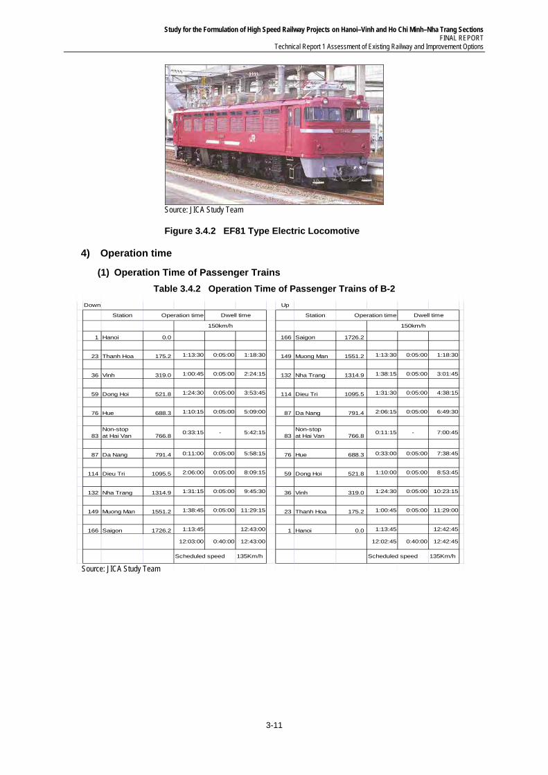
Study for the Formulation of High Speed Railway Projects on Hanoi–Vinh and Ho Chi Minh–Nha Trang Sections FINAL REPORT
Technical Report 1 Assessment of Existing Railway and Improvement Options
3-11
Source: JICA Study Team
Figure 3.4.2 EF81 Type Electric Locomotive
4) Operation time
(1) Operation Time of Passenger Trains
Table 3.4.2 Operation Time of Passenger Trains of B-2
Down Up
Station Operation time Station Operation time
1 Hanoi 0.0 166 Saigon 1726.2
23 Thanh Hoa 175.2 1:13:30 0:05:00 1:18:30 149 Muong Man 1551.2 1:13:30 0:05:00 1:18:30
36 Vinh 319.0 1:00:45 0:05:00 2:24:15 132 Nha Trang 1314.9 1:38:15 0:05:00 3:01:45
59 Dong Hoi 521.8 1:24:30 0:05:00 3:53:45 114 Dieu Tri 1095.5 1:31:30 0:05:00 4:38:15
76 Hue 688.3 1:10:15 0:05:00 5:09:00 87 Da Nang 791.4 2:06:15 0:05:00 6:49:30
83Non-stopat Hai Van 766.8
0:33:15 - 5:42:1583
Non-stopat Hai Van 766.8
0:11:15 - 7:00:45
87 Da Nang 791.4 0:11:00 0:05:00 5:58:15 76 Hue 688.3 0:33:00 0:05:00 7:38:45
114 Dieu Tri 1095.5 2:06:00 0:05:00 8:09:15 59 Dong Hoi 521.8 1:10:00 0:05:00 8:53:45
132 Nha Trang 1314.9 1:31:15 0:05:00 9:45:30 36 Vinh 319.0 1:24:30 0:05:00 10:23:15
149 Muong Man 1551.2 1:38:45 0:05:00 11:29:15 23 Thanh Hoa 175.2 1:00:45 0:05:00 11:29:00
166 Saigon 1726.2 1:13:45 12:43:00 1 Hanoi 0.0 1:13:45 12:42:45
12:03:00 0:40:00 12:43:00 12:02:45 0:40:00 12:42:45
Scheduled speed 135Km/h Scheduled speed 135Km/h
Dwell time Dwell time
150km/h 150km/h
Source: JICA Study Team
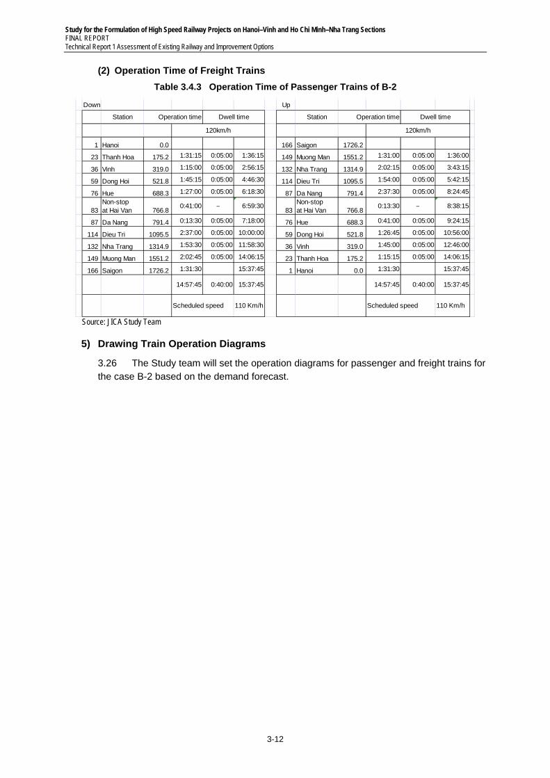
Study for the Formulation of High Speed Railway Projects on Hanoi–Vinh and Ho Chi Minh–Nha Trang Sections FINAL REPORT Technical Report 1 Assessment of Existing Railway and Improvement Options
3-12
(2) Operation Time of Freight Trains
Table 3.4.3 Operation Time of Passenger Trains of B-2
Down Up
Station Operation time Station Operation time
1 Hanoi 0.0 166 Saigon 1726.2
23 Thanh Hoa 175.2 1:31:15 0:05:00 1:36:15 149 Muong Man 1551.2 1:31:00 0:05:00 1:36:00
36 Vinh 319.0 1:15:00 0:05:00 2:56:15 132 Nha Trang 1314.9 2:02:15 0:05:00 3:43:15
59 Dong Hoi 521.8 1:45:15 0:05:00 4:46:30 114 Dieu Tri 1095.5 1:54:00 0:05:00 5:42:15
76 Hue 688.3 1:27:00 0:05:00 6:18:30 87 Da Nang 791.4 2:37:30 0:05:00 8:24:45
83Non-stopat Hai Van 766.8
0:41:00 - 6:59:3083
Non-stopat Hai Van 766.8
0:13:30 - 8:38:15
87 Da Nang 791.4 0:13:30 0:05:00 7:18:00 76 Hue 688.3 0:41:00 0:05:00 9:24:15
114 Dieu Tri 1095.5 2:37:00 0:05:00 10:00:00 59 Dong Hoi 521.8 1:26:45 0:05:00 10:56:00
132 Nha Trang 1314.9 1:53:30 0:05:00 11:58:30 36 Vinh 319.0 1:45:00 0:05:00 12:46:00
149 Muong Man 1551.2 2:02:45 0:05:00 14:06:15 23 Thanh Hoa 175.2 1:15:15 0:05:00 14:06:15
166 Saigon 1726.2 1:31:30 15:37:45 1 Hanoi 0.0 1:31:30 15:37:45
14:57:45 0:40:00 15:37:45 14:57:45 0:40:00 15:37:45
Scheduled speed 110 Km/h Scheduled speed 110 Km/h
Dwell time Dwell time
120km/h 120km/h
Source: JICA Study Team
5) Drawing Train Operation Diagrams
3.26 The Study team will set the operation diagrams for passenger and freight trains for the case B-2 based on the demand forecast.
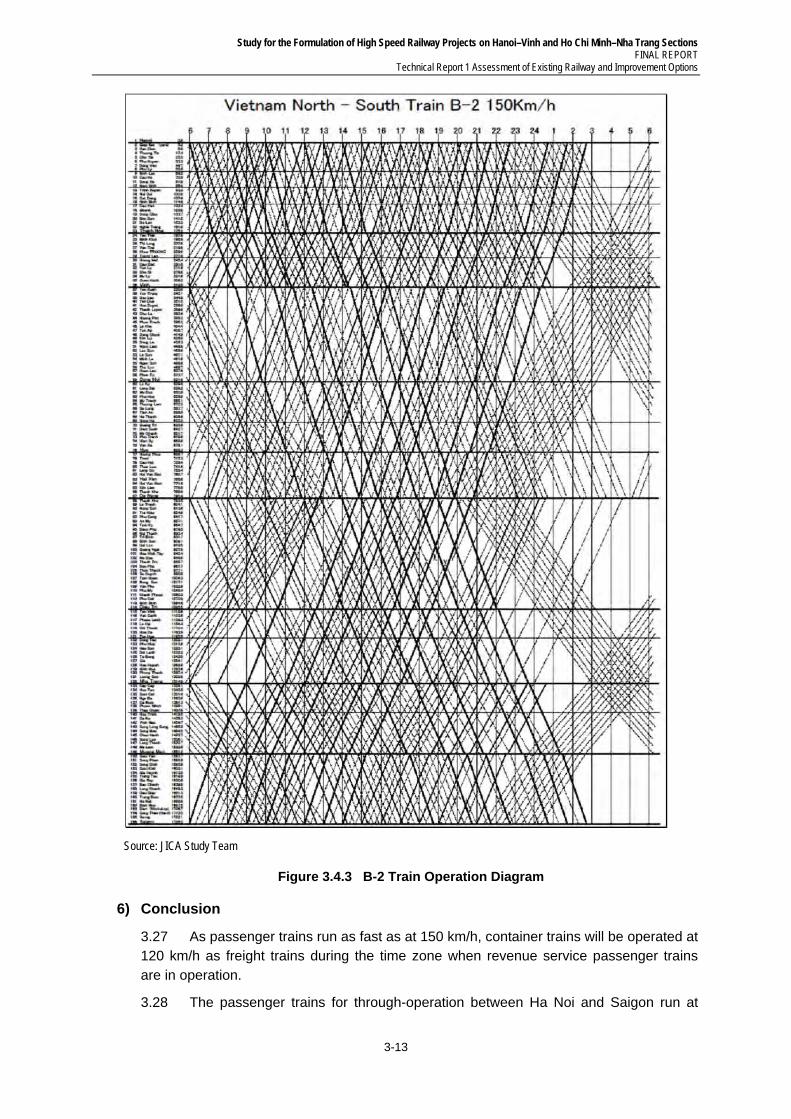
Study for the Formulation of High Speed Railway Projects on Hanoi–Vinh and Ho Chi Minh–Nha Trang Sections FINAL REPORT
Technical Report 1 Assessment of Existing Railway and Improvement Options
3-13
Source: JICA Study Team
Figure 3.4.3 B-2 Train Operation Diagram
6) Conclusion
3.27 As passenger trains run as fast as at 150 km/h, container trains will be operated at 120 km/h as freight trains during the time zone when revenue service passenger trains are in operation.
3.28 The passenger trains for through-operation between Ha Noi and Saigon run at
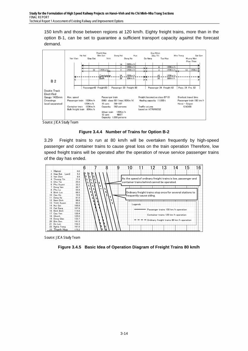
Study for the Formulation of High Speed Railway Projects on Hanoi–Vinh and Ho Chi Minh–Nha Trang Sections FINAL REPORT Technical Report 1 Assessment of Existing Railway and Improvement Options
3-14
150 km/h and those between regions at 120 km/h. Eighty freight trains, more than in the option B-1, can be set to guarantee a sufficient transport capacity against the forecast demand.
Source: JICA Study Team
Figure 3.4.4 Number of Trains for Option B-2
3.29 Freight trains to run at 80 km/h will be overtaken frequently by high-speed passenger and container trains to cause great loss on the train operation Therefore, low speed freight trains will be operated after the operation of revue service passenger trains of the day has ended.
1 Hanoi 0.02 Giap Bat (yard) 5.23 Van Dien 8.94 Thuong Tin 17.45 Cho Tia 25.56 Phu Xuyen 33.37 Dong Van 44.78 Phu Ly 55.99 Binh Luc 66.5
10 Cau Ho 72.911 Dang Xa 81.012 Nam Dinh 86.813 Trinh Xuyen 93.314 Nui Goi 100.815 Cat Dang 107.616 Ninh Binh 114.617 Cau Yen 120.418 Ghenh 125.019 Dong Glao 133.720 Bim Son 141.521 Do Len 152.322 Nghia Trang 161.0
23 Thanh Hoa 175.2
Ordinary freight trains 80 km/h operation
Legends
Passenger trains 150 km/h operation
Container trains 120 km/h operation
1610 11 12 136 7 8 9 14 15
As the speed of ordinary freight trains is low, passenger and container trains behind cannot be operated.
Ordinary freight trains stop once for several stations to frequently cause siding.
Source: JICA Study Team
Figure 3.4.5 Basic Idea of Operation Diagram of Freight Trains 80 km/h
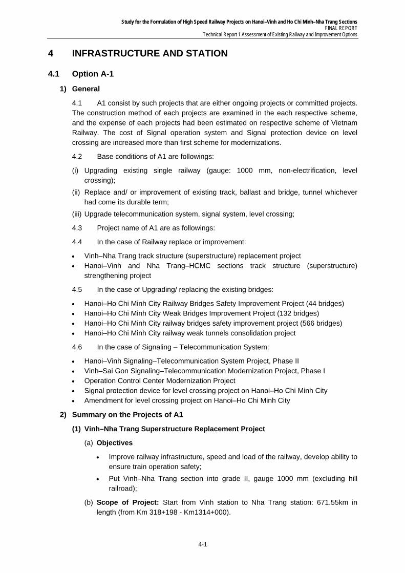
Study for the Formulation of High Speed Railway Projects on Hanoi–Vinh and Ho Chi Minh–Nha Trang Sections FINAL REPORT
Technical Report 1 Assessment of Existing Railway and Improvement Options
4-1
4 INFRASTRUCTURE AND STATION
4.1 Option A-1
1) General
4.1 A1 consist by such projects that are either ongoing projects or committed projects. The construction method of each projects are examined in the each respective scheme, and the expense of each projects had been estimated on respective scheme of Vietnam Railway. The cost of Signal operation system and Signal protection device on level crossing are increased more than first scheme for modernizations.
4.2 Base conditions of A1 are followings:
(i) Upgrading existing single railway (gauge: 1000 mm, non-electrification, level crossing);
(ii) Replace and/ or improvement of existing track, ballast and bridge, tunnel whichever had come its durable term;
(iii) Upgrade telecommunication system, signal system, level crossing;
4.3 Project name of A1 are as followings:
4.4 In the case of Railway replace or improvement:
Vinh–Nha Trang track structure (superstructure) replacement project Hanoi–Vinh and Nha Trang–HCMC sections track structure (superstructure)
strengthening project
4.5 In the case of Upgrading/ replacing the existing bridges:
Hanoi–Ho Chi Minh City Railway Bridges Safety Improvement Project (44 bridges) Hanoi–Ho Chi Minh City Weak Bridges Improvement Project (132 bridges) Hanoi–Ho Chi Minh City railway bridges safety improvement project (566 bridges) Hanoi–Ho Chi Minh City railway weak tunnels consolidation project
4.6 In the case of Signaling – Telecommunication System:
Hanoi–Vinh Signaling–Telecommunication System Project, Phase II Vinh–Sai Gon Signaling–Telecommunication Modernization Project, Phase I Operation Control Center Modernization Project Signal protection device for level crossing project on Hanoi–Ho Chi Minh City Amendment for level crossing project on Hanoi–Ho Chi Minh City
2) Summary on the Projects of A1
(1) Vinh–Nha Trang Superstructure Replacement Project
(a) Objectives
Improve railway infrastructure, speed and load of the railway, develop ability to ensure train operation safety;
Put Vinh–Nha Trang section into grade II, gauge 1000 mm (excluding hill railroad);
(b) Scope of Project: Start from Vinh station to Nha Trang station: 671.55km in length (from Km 318+198 - Km1314+000).
Study for the Formulation of High Speed Railway Projects on Hanoi–Vinh and Ho Chi Minh–Nha Trang Sections FINAL REPORT Technical Report 1 Assessment of Existing Railway and Improvement Options
4-2
(c) Specifications
Gauge: grade 2 gauge 1000mm;
Design speed Vmax=100 Km/h;
Plane: like existing one, local alignment Rmin = 600 m;
Ip like existing one
Ldd ≥ 400 m;
Superstructure on main line Rail P50; L=25 m; PC sleeper;
Track formation: Advantage 5,7 m; Disadvantage: ballast retaining wall;
(d) Scale of Project
Replacement of RC K1, K2, steel sleepers by PC sleepers, strengthening track and laying more track no. 3 for double-track stations on Hanoi–Ho Chi Minh City Railway, Vinh–Nha Trang section;
Alignment: upgrade 49 points R<600m total length 20,09Km;
Track formation: embankment, expand track formation with length 671,55 km;
Construct ditch for drainage is 21,37 km long;
Construct ballast retaining wall with length 35,77 km.
Consolidate slope 62.935 km.
Overhaul superstructure of main line is 671,55 km long;
Replace 342 turnout sets on main line;
Construct 11 new RC bridge and 55 culverts on alignment;
Upgrade 107 level crossings;
Upgrade 92 stations, of which laying more track no. 3 for existing 07 stations of double tracks, lengthen the track in 17 stations, overhaul 68 stations.
(e) Land Use Area: Permanent land occupation for alignment of station expansion is 21,26 ha.
(f) Project Cost: 3.960 billion VND by scheme; in which 1.414 billion VND in stage 1;
(g) Fund: State fund;
(h) Duration: 3 years
(2) Hanoi–Vinh and Nha Trang–HCMC Sections Track Structure Strengthening Projects
(a) Objectives: Improve railway infrastructure, ability to ensure running train safety;
(b) Scope of Project: Hanoi–Ho Chi Minh City railway from Km0 - 318+198 and Km1314–Km 1726;
(c) Specifications
Gauge: grade 2 gauge 1000 mm;
Design speed Vmax=100 km/h;
Plane: like existing one, local alignment Rmin = 600 m;
Ip like existing one;
Ldd ≥ 400 m;
Study for the Formulation of High Speed Railway Projects on Hanoi–Vinh and Ho Chi Minh–Nha Trang Sections FINAL REPORT
Technical Report 1 Assessment of Existing Railway and Improvement Options
4-3
Superstructure on main line Rail P50; L=25 m; PC sleeper;
Track formation: 5,7 m;
(d) Scale of Project
Overall overhaul, replacement for existing rail, sleeper with rail P50 in 15.48 km length;
Remake ballast foundation, replacement for existing sleepers with PC
Sleeper: 95 km.
Synchronous weak soil treatment: 74,38 km;
Replacement for 152 turnout sets on main line
(e) Project Cost: 3.689 bill VND;
(f) Fund: State fund;
(g) Duration: 3 years;
(3) 44 bridges improvement project Hanoi-Hochiminh City Railway Line Bridges Safety Improvement Project (44 Bridges)
(a) Objectives
To enhance safety during train operation;
To enhance safety for other traffic activities and the residents living along the railway under the Project scope;
To shorten train routes;
(b) Scope of project: Hanoi–Hochiminh City Railway Line Km111+700–1551+700
(c) Specifications
Design Class: permanent bridge, 1000mm-gauge track;
Train Load: T15D;
Load of Road on Bridge: Steel-girder bridge 300Kg/m2; ballasted concrete-girder bridge 1,000 kg/m2;
Design Speed: Vpassenger=100 km/h; Vfreight=80 km/h (in some bridges, this speed can be increased to 120 km/h if possible);
Clearance of Railway Bridge: Height H=5.3 m; Width B= 4 m;
Flood Frequency: P=1% for bridges on realigned section
Horizontal Alignment: Rmin = 300 m; and R min ≥ 200 m on Cua Rao bridge
Ip: as present
L effective Length ≥ 500 m;
Track Bed: 5.7 m on rail-welding case and Bmin = 5.5 m for the remaining.
(d) Scope of Investment
Rehabilitating 44 bridges and access roads (of which 8 bridge will be realigned and the remaining 36 bridges will be located at the same places);
Upgrading and improving 22 level crossings, of which 10 level crossings will be of automatic warning type, 2 level crossings will be of signage type, and the remaining 10 will be of guardsmen type;
Study for the Formulation of High Speed Railway Projects on Hanoi–Vinh and Ho Chi Minh–Nha Trang Sections FINAL REPORT Technical Report 1 Assessment of Existing Railway and Improvement Options
4-4
Constructing 3 railroad under-bridges and 23 box culverts;
Upgrading, improving, and constructing 14 underpasses;
Constructing 2 flyovers to the south of Ninh Binh station and to the south of Do Len station;
Constructing Ninh Binh station;
Purchasing 12 types of equipment for repairing and maintaining railway and bridges.
(e) Land Use Area: 74.53ha of land will be permanently used for realignment section due to station expansion.
(f) Project Cost: VND2,498 billion;
(g) Fund: VND1,102 billion from State budget + ¥19,663 billion Yen from ODA loan;
(h) Duration: 7 years (2005–2012);
(4) 132 bridges Safety Improvement Project; Improvement and Upgrading of Remaining Weak Bridges on Hanoi–Hochiminh City Railway Line (132 bridges);
(a) Project Objectives: To use a uniform 4.1T/m load for Belgium locomotive-using trains on the entire Hanoi–Hochiminh City Railway Line. The load of upgraded bridges must be equivalent to that of standard trains, namely T14 for reused girders and abutments, and T16 for new abutments.
(b) Scope of project: Hanoi–Hochiminh City Railway Line, Km791+400 - 1726+200
(c) Specifications
Track Gauge: 1,000 mm-gauge track;
Track Class: 2
Train Load: T14 for reused girders and abutments, and T16 for new abutments;
Design Flood Frequency: P=1% for medium-span and long-span bridges, and P=2% for small-span bridges and culverts.
Minimum width of Track Bed on Straight Line: B=5.7 m;
Horizontal Curve Radius: Rmin = 600 m;
Maximum Vertical Gradient: Ip =12‰; Minimum length of slope: L=150 m.
(d) Scope of investment: Improving and upgrading 132 weak bridges on Da Nang–Hochiminh City section to use a uniform 4.1T/m load for Belgium locomotive-using trains on the entire Hanoi - Hochiminh City Railway Line.
(e) Land Use Area: 15.1ha of land will be permanently used for realignment section due to station expansion.
(f) Project Cost: VND1,433 billion;
(g) Fund: State fund;
(h) Duration: 4 years (2008–2012)
Study for the Formulation of High Speed Railway Projects on Hanoi–Vinh and Ho Chi Minh–Nha Trang Sections FINAL REPORT
Technical Report 1 Assessment of Existing Railway and Improvement Options
4-5
(5) 566 Bridges Safety Improvement Project Hanoi–Ho Chi Minh City Railway Line Bridges Safety Improvement Project (566 bridges)
(a) Project Objectives: Upgrading and improving bridges in order to ensure train operation safety;
(b) Scope of Project: The North-South Railway Line from Km791+400 to Km1726+200.
(c) Specifications
Grade of Track: grade 2 – 1000 mm gauge;
Design Speed Vmax=100 km/h;
Horizontal Alignment: same as the existing; local realignment Rmin = 600 m;
Ip same as the existing;
Ldd ≥ 400 m;
Superstructure: Main line Rail P50; L=25 m; PC sleeper;
(d) Scale of Investment: Upgrading, improving 566 bridges on Da Nang–Ho Chi Minh City section to unify the operated train load with Belgium +4,1T/m on the whole Hanoi–Ho Chi Minh Line.
(e) Project Cost: 2,284 billion Vietnam Dong;
(f) Fund: State budget;
(g) Duration: 8 years (2012–2020);
(6) Weak 22 Tunnels Consolidation Project; Reinforcement of Weak Tunnels on Hanoi–Ho Chi Minh City Railway Line
(a) Project Objectives: To ensure the safety of train operation and remove the speed limit locations;
(b) Scope of Project: The North-South railway line from Km455+432–Km1310+888
(c) Specifications
Railway Grade: grade 2 with gauge 1000 mm;
Designed Speed Vmax=100 km/h;
Horizontal Alignment: as existing; local realignment: Rmin = 60 0m;
Ip is as existing;
Ldd ≥ 400 m;
Superstructure of Main Line: Rail P50; L=25 m; pre-stressed concrete sleeper;
(d) Scale of Investment: This project is only for rehabilitation and reinforcement of the weak tunnel to ensure train operation safety, removing the speed limit and meet transportation need of this railway line. The project essentially keep technical standards of the line, such as: horizontal alignment, profile, limited gradient. So, scale of investment is:
Reinforcement, repairing and upgrading locally tunnel lining structure;
New-built of tunnel lining in some manic damaged section.
(e) Project Cost: 1.911 billion VND;
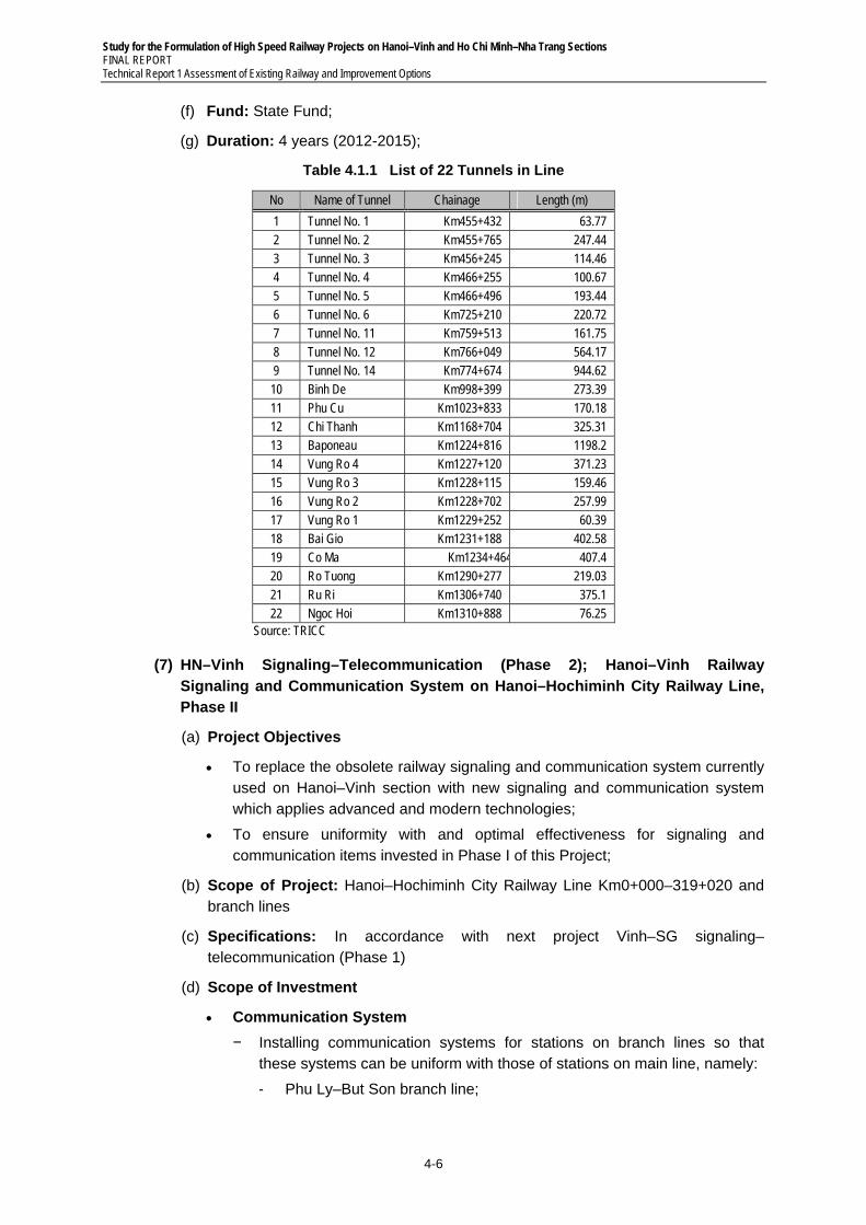
Study for the Formulation of High Speed Railway Projects on Hanoi–Vinh and Ho Chi Minh–Nha Trang Sections FINAL REPORT Technical Report 1 Assessment of Existing Railway and Improvement Options
4-6
(f) Fund: State Fund;
(g) Duration: 4 years (2012-2015);
Table 4.1.1 List of 22 Tunnels in Line
No Name of Tunnel Chainage Length (m)
1 Tunnel No. 1 Km455+432 63.77 2 Tunnel No. 2 Km455+765 247.44 3 Tunnel No. 3 Km456+245 114.46 4 Tunnel No. 4 Km466+255 100.67 5 Tunnel No. 5 Km466+496 193.44 6 Tunnel No. 6 Km725+210 220.72 7 Tunnel No. 11 Km759+513 161.75 8 Tunnel No. 12 Km766+049 564.17 9 Tunnel No. 14 Km774+674 944.62 10 Binh De Km998+399 273.39 11 Phu Cu Km1023+833 170.18 12 Chi Thanh Km1168+704 325.31 13 Baponeau Km1224+816 1198.2 14 Vung Ro 4 Km1227+120 371.23 15 Vung Ro 3 Km1228+115 159.46 16 Vung Ro 2 Km1228+702 257.99 17 Vung Ro 1 Km1229+252 60.39 18 Bai Gio Km1231+188 402.58 19 Co Ma Km1234+464 407.4 20 Ro Tuong Km1290+277 219.03 21 Ru Ri Km1306+740 375.1 22 Ngoc Hoi Km1310+888 76.25
Source: TRICC
(7) HN–Vinh Signaling–Telecommunication (Phase 2); Hanoi–Vinh Railway Signaling and Communication System on Hanoi–Hochiminh City Railway Line, Phase II
(a) Project Objectives
To replace the obsolete railway signaling and communication system currently used on Hanoi–Vinh section with new signaling and communication system which applies advanced and modern technologies;
To ensure uniformity with and optimal effectiveness for signaling and communication items invested in Phase I of this Project;
(b) Scope of Project: Hanoi–Hochiminh City Railway Line Km0+000–319+020 and branch lines
(c) Specifications: In accordance with next project Vinh–SG signaling–telecommunication (Phase 1)
(d) Scope of Investment
Communication System
− Installing communication systems for stations on branch lines so that these systems can be uniform with those of stations on main line, namely:
- Phu Ly–But Son branch line;
Study for the Formulation of High Speed Railway Projects on Hanoi–Vinh and Ho Chi Minh–Nha Trang Sections FINAL REPORT
Technical Report 1 Assessment of Existing Railway and Improvement Options
4-7
- Bim Son–Bim Son Industrial Park branch line; and
- Cau Giat –Nghia Dan branch line.
− SDH equipment at a transmission speed of STM-1 (potential be increased to STM-4), de-multiplexers/multiplexers D&I, and dedicated digital telephone system will be used for the following branch lines:
− Establishing protective rings at Vinh and Hanoi cities
- Establishing rings for signaling transmission lines.
- Connecting to VNPT at Hanoi, Nam Dinh, Thanh Hoa, Cau Giat, and Vinh via interchange trunk lines.
- Establishing data communication system.
Signaling System
− Installing centrally electrifying equipment (micro-processing interlocking) for 34 stations;
− Installing axle counter-based blocking equipment for 34 stations;
− Establishing Central Train Control (CTC) on Hanoi–Vinh section.
− Synchronization and Training System;
(e) Land Use Area:
(f) Project Cost: VND 1,082 billion (ODA loan: VND847 billion)
(g) Fund: ODA loan from French Government and Vietnam reciprocal capital;
(h) Duration: 4 years (2007–2010); Project is on the way.
(8) Vinh–SG Signaling–Telecommunication (Phase 1); Modernization of Signaling and Telecommunication System on Vinh–Ho Chi Minh City Section on The North-South Railway Line-Phase 1”
(a) Project Objectives: Reject the backward and weakness of the existing signaling and telecommunication system
(b) Scope of Project: Km 319+020–Km 1726 section on North-South railway line
(c) Scale of Project
Telecommunication System
− Transmission system
- Building the optical cable suspension line – Type of G625 - 12 strands with 1.150km long and the add – and - drop system from Vinh station to Nha Trang Station;
- Installing device to connect the loop protection: 1.0 point;
- Installing SDH transmission device and NMS transmission network management system from Vinh to Nha Trang.
− Switching System: Switching devices (all in the switching monitoring and management system: 26.000 telephones and installing subscriber: 950 telephones.
− Specialized Communication System: Building the coaxial cable along the line and installing dialog box at section: 1.577 km; building the local communication system: 95 stations; installing devices (including the
Study for the Formulation of High Speed Railway Projects on Hanoi–Vinh and Ho Chi Minh–Nha Trang Sections FINAL REPORT Technical Report 1 Assessment of Existing Railway and Improvement Options
4-8
monitoring system): 97 stations; clock and time distribution system: 97 stations.
− Other sync Communication Items: Installing lightening protection and earthing system: 95 stations; stand-by equipment: 97 stations; maintenance vehicle: 11 stations. Technical assistance: 97 stations.
Signaling System
− Interlocking device in station: Building, installing devices of centralized control station to control relay interlocking in combination with axle counter for 316 turnouts of stations from Da Nang to Sai Gon.
− Block system: Building the semi-automatic block section in combination with the axle counter for 72 stations from Da Nang to Sai Gon.
− Train operation monitoring system and computer-base measurement:
− Building train operation monitoring system and computer-base measurement for 54 stations from Dieu Tri to Sai Gon.
− Turnout control system at section: 04 sets (at Chu Lai, My Trang, Ru Ri and Giac Lan).
− Building the signal maintenance and inspection station: 4 stations.
− Technical assistance: Supporting for 72 stations from Da Nang to Sai Gon.
Other Relevant Sync Works
− Station: 120 stations, power feeding: 116 stations, superstructure: serve the signal installation of 72 stations from Da Nang to Sai Gon.
(d) Project Cost: 3.059 billion Vietnam Dong (in which foreign loan of 2.003 billion Vietnam Dong);
(e) Fund: Chinese preferential loan and Vietnamese counterpart fund;
(f) Duration: 3 years (2011–2013);
(9) Operation Control Center Railway Operation Control Center (OCC) Modernization
(a) Project Objectives: Investing in railway signaling and telecommunication infrastructure, promoting the efficiency of investment projects for the future and existing railway infrastructure to improve the train operation schedule, dispatching passenger and freight train operation, dispatching rolling stocks; management and maintenance of infrastructure is a pressing demand to allow the high transport capacity to meet the better services for customers, providing better transportation services, attracting a mass volume transport. OCC is invested with high level of modern and has ability to extend and can connect with other relevant system on the North- South Railway line.
(b) Scope of Project
OCC at the head office of Vietnam Railways, Hanoi.
OCC of the North region is placed at Hanoi OCC.
OCC of the South region is placed at Sai Gon passenger Transport Company, Ho Chi Minh City.
Stations have operations of shunting, stations on all railway lines of Vietnam.
Study for the Formulation of High Speed Railway Projects on Hanoi–Vinh and Ho Chi Minh–Nha Trang Sections FINAL REPORT
Technical Report 1 Assessment of Existing Railway and Improvement Options
4-9
(c) Specification: Current EU norms applied to railway transport and relevant Vietnamese standards.
(d) Scale of Investment
Main Operation Control Center
− Main OCC and OCC of the north region: Equipping the host, workstation system for dispatcher.
− Planning Unit: Equipping communication system, prints; control station system; planning station system.
− Unit of stand-by control and training: Equipping host integrated COM and ADM; host system- simulation system; control station system; and communication system.
− Unit of management, maintenance and overhaul: Equipping communication system and control station system.
OCC of the South Region: Equipping the work station for dispatcher; prints and projector.
Equipping for Locomotive: Equipment such GPS, GSM, WLAN, MMI/push-button, antenna over 350 locomotives of Vietnam Railways.
− At stations: Equipping laptop and portable equipments for data input; equipping WLAN system for stations without GSM wave.
− Other relevant sync works;
(e) Project Cost: 246 billion Vietnam Dong (ODA loan: 210 billion Vietnam Dong ~ 10.2 million EURO)
(f) Fund: Germany ODA loan and Vietnamese counterpart fund;
(g) Duration: 36 months (2007-2010), Project is on the way.
(10) Crossing Automatization with Signal Protection Device
4.7 This project is concerned to next level crossing adjustment project. Signal safety system and warning device of level crossing would be installed by this project except civil works.
(11) Amendment for Level crossing Project on Hanoi–Ho chi Minh City Railway
4.8 Adjustment of level crossing project on the North-South Railway Line;
(a) Project Objectives
Improving, upgrading, and gathering the level crossing system on the North – South Railway line to improve the traffic safety.
Concentrating the investment on the level crossings with high traffic volume.
Priority over the new collector to gather level crossings and decrease intersections on the North-South Railway line.
For the favorable locations of intersection, priority to design the grade interchange (underpass) instead of intersection at grade (level crossing).
(b) Scope of Project: The North-South Railway Line;
(c) Specification
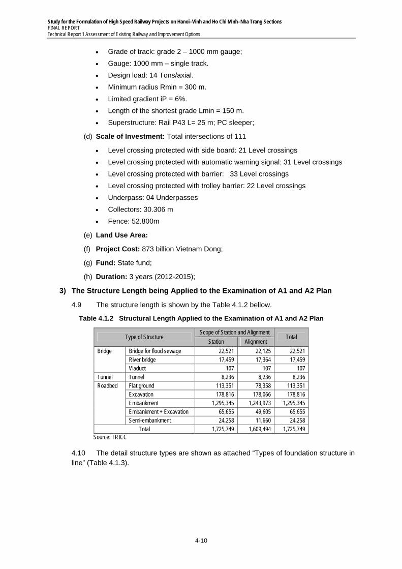
Study for the Formulation of High Speed Railway Projects on Hanoi–Vinh and Ho Chi Minh–Nha Trang Sections FINAL REPORT Technical Report 1 Assessment of Existing Railway and Improvement Options
4-10
Grade of track: grade 2 – 1000 mm gauge;
Gauge: 1000 mm – single track.
Design load: 14 Tons/axial.
Minimum radius Rmin = 300 m.
Limited gradient iP = 6%.
Length of the shortest grade Lmin = 150 m.
Superstructure: Rail P43 L= 25 m; PC sleeper;
(d) Scale of Investment: Total intersections of 111
Level crossing protected with side board: 21 Level crossings
Level crossing protected with automatic warning signal: 31 Level crossings
Level crossing protected with barrier: 33 Level crossings
Level crossing protected with trolley barrier: 22 Level crossings
Underpass: 04 Underpasses
Collectors: 30.306 m
Fence: 52.800m
(e) Land Use Area:
(f) Project Cost: 873 billion Vietnam Dong;
(g) Fund: State fund;
(h) Duration: 3 years (2012-2015);
3) The Structure Length being Applied to the Examination of A1 and A2 Plan
4.9 The structure length is shown by the Table 4.1.2 bellow.
Table 4.1.2 Structural Length Applied to the Examination of A1 and A2 Plan
Type of Structure Scope of Station and Alignment
Total Station Alignment
Bridge Bridge for flood sewage 22,521 22,125 22,521 River bridge 17,459 17,364 17,459 Viaduct 107 107 107
Tunnel Tunnel 8,236 8,236 8,236 Roadbed Flat ground 113,351 78,358 113,351
Excavation 178,816 178,066 178,816 Embankment 1,295,345 1,243,973 1,295,345 Embankment + Excavation 65,655 49,605 65,655 Semi-embankment 24,258 11,660 24,258
Total 1,725,749 1,609,494 1,725,749 Source: TRICC
4.10 The detail structure types are shown as attached “Types of foundation structure in line” (Table 4.1.3).
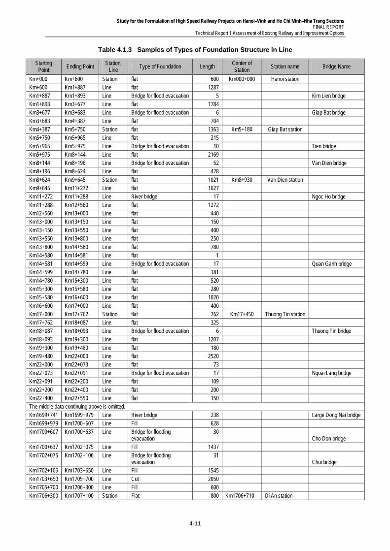
Study for the Formulation of High Speed Railway Projects on Hanoi–Vinh and Ho Chi Minh–Nha Trang Sections FINAL REPORT
Technical Report 1 Assessment of Existing Railway and Improvement Options
4-11
Table 4.1.3 Samples of Types of Foundation Structure in Line
Starting Point
Ending Point Station,
Line Type of Foundation Length
Center of Station
Station name Bridge Name
Km+000 Km+600 Station flat 600 Km000+000 Hanoi station Km+600 Km1+887 Line flat 1287 Km1+887 Km1+893 Line Bridge for flood evacuation 5 Kim Lien bridge Km1+893 Km3+677 Line flat 1784 Km3+677 Km3+683 Line Bridge for flood evacuation 6 Giap Bat bridge Km3+683 Km4+387 Line flat 704 Km4+387 Km5+750 Station flat 1363 Km5+180 Giap Bat station Km5+750 Km5+965 Line flat 215 Km5+965 Km5+975 Line Bridge for flood evacuation 10 Tien bridge Km5+975 Km8+144 Line flat 2169 Km8+144 Km8+196 Line Bridge for flood evacuation 52 Van Dien bridge Km8+196 Km8+624 Line flat 428 Km8+624 Km9+645 Station flat 1021 Km8+930 Van Dien station Km9+645 Km11+272 Line flat 1627 Km11+272 Km11+288 Line River bridge 17 Ngoc Ho bridge Km11+288 Km12+560 Line flat 1272 Km12+560 Km13+000 Line flat 440 Km13+000 Km13+150 Line flat 150 Km13+150 Km13+550 Line flat 400 Km13+550 Km13+800 Line flat 250 Km13+800 Km14+580 Line flat 780 Km14+580 Km14+581 Line flat 1 Km14+581 Km14+599 Line Bridge for flood evacuation 17 Quan Ganh bridge Km14+599 Km14+780 Line flat 181 Km14+780 Km15+300 Line flat 520 Km15+300 Km15+580 Line flat 280 Km15+580 Km16+600 Line flat 1020 Km16+600 Km17+000 Line flat 400 Km17+000 Km17+762 Station flat 762 Km17+450 Thuong Tin station Km17+762 Km18+087 Line flat 325 Km18+087 Km18+093 Line Bridge for flood evacuation 6 Thuong Tin bridge Km18+093 Km19+300 Line flat 1207 Km19+300 Km19+480 Line flat 180 Km19+480 Km22+000 Line flat 2520 Km22+000 Km22+073 Line flat 73 Km22+073 Km22+091 Line Bridge for flood evacuation 17 Ngoai Lang bridge Km22+091 Km22+200 Line flat 109 Km22+200 Km22+400 Line flat 200 Km22+400 Km22+550 Line flat 150 The middle data continuing above is omitted. Km1699+741 Km1699+979 Line River bridge 238 Large Dong Nai bridge Km1699+979 Km1700+607 Line Fill 628 Km1700+607 Km1700+637 Line Bridge for flooding
evacuation 30
Cho Don bridge
Km1700+637 Km1702+075 Line Fill 1437 Km1702+075 Km1702+106 Line Bridge for flooding
evacuation 31
Chui bridge
Km1702+106 Km1703+650 Line Fill 1545 Km1703+650 Km1705+700 Line Cut 2050 Km1705+700 Km1706+300 Line Fill 600 Km1706+300 Km1707+100 Station Flat 800 Km1706+710 Di An station
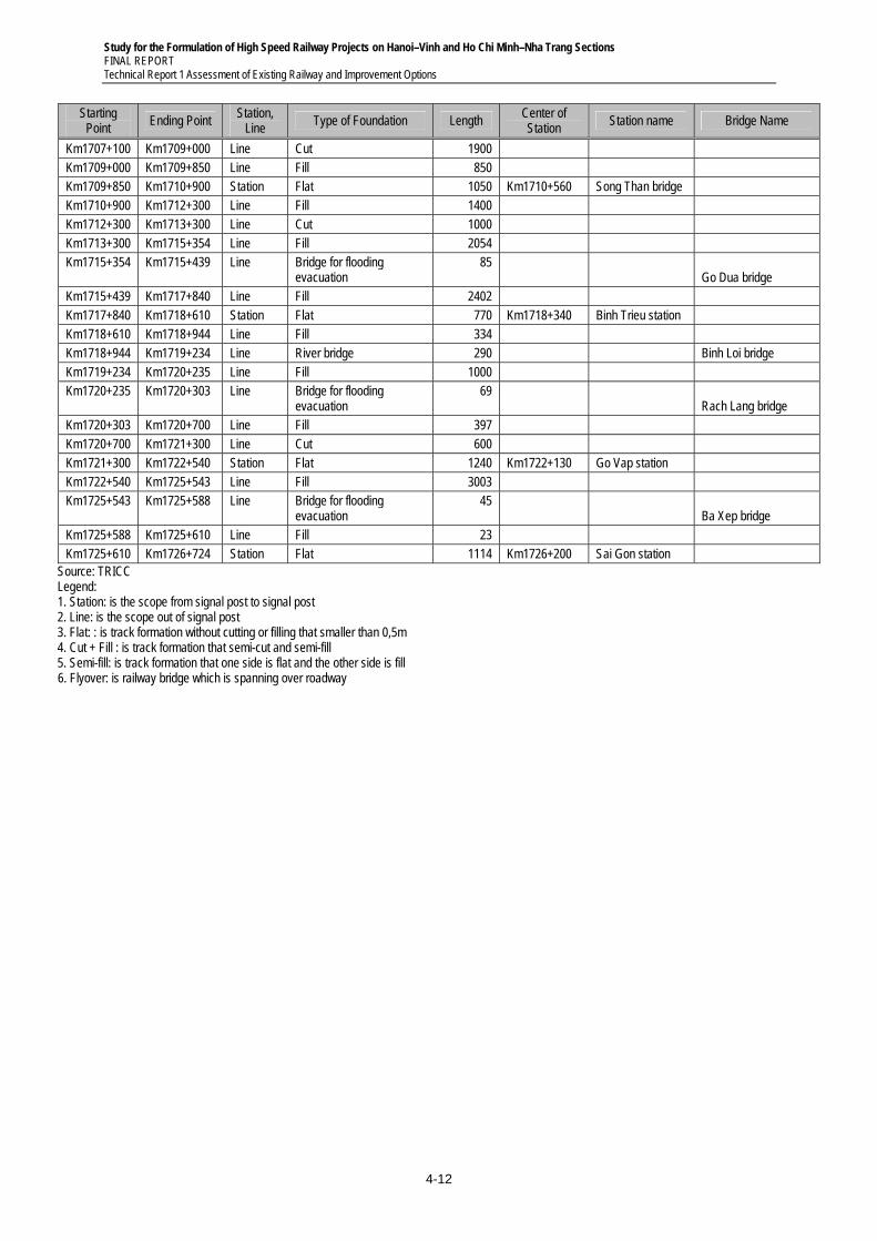
Study for the Formulation of High Speed Railway Projects on Hanoi–Vinh and Ho Chi Minh–Nha Trang Sections FINAL REPORT Technical Report 1 Assessment of Existing Railway and Improvement Options
4-12
Starting Point
Ending Point Station,
Line Type of Foundation Length
Center of Station
Station name Bridge Name
Km1707+100 Km1709+000 Line Cut 1900 Km1709+000 Km1709+850 Line Fill 850 Km1709+850 Km1710+900 Station Flat 1050 Km1710+560 Song Than bridge Km1710+900 Km1712+300 Line Fill 1400 Km1712+300 Km1713+300 Line Cut 1000 Km1713+300 Km1715+354 Line Fill 2054 Km1715+354 Km1715+439 Line Bridge for flooding
evacuation 85
Go Dua bridge
Km1715+439 Km1717+840 Line Fill 2402 Km1717+840 Km1718+610 Station Flat 770 Km1718+340 Binh Trieu station Km1718+610 Km1718+944 Line Fill 334 Km1718+944 Km1719+234 Line River bridge 290 Binh Loi bridge Km1719+234 Km1720+235 Line Fill 1000 Km1720+235 Km1720+303 Line Bridge for flooding
evacuation 69
Rach Lang bridge
Km1720+303 Km1720+700 Line Fill 397 Km1720+700 Km1721+300 Line Cut 600 Km1721+300 Km1722+540 Station Flat 1240 Km1722+130 Go Vap station Km1722+540 Km1725+543 Line Fill 3003 Km1725+543 Km1725+588 Line Bridge for flooding
evacuation 45
Ba Xep bridge
Km1725+588 Km1725+610 Line Fill 23 Km1725+610 Km1726+724 Station Flat 1114 Km1726+200 Sai Gon station
Source: TRICC Legend: 1. Station: is the scope from signal post to signal post 2. Line: is the scope out of signal post 3. Flat: : is track formation without cutting or filling that smaller than 0,5m 4. Cut + Fill : is track formation that semi-cut and semi-fill 5. Semi-fill: is track formation that one side is flat and the other side is fill 6. Flyover: is railway bridge which is spanning over roadway
Study for the Formulation of High Speed Railway Projects on Hanoi–Vinh and Ho Chi Minh–Nha Trang Sections FINAL REPORT
Technical Report 1 Assessment of Existing Railway and Improvement Options
4-13
4.2 Option A-2
1) General
4.11 In order to increase train numbers per day according the objection of option A2, shortening of train operation time and installation of pass-by station/interchange station were examined. It was result that 18 pass-by stations are necessary to operate 50 train numbers per day. The cost of option A2 had been estimated according to each construction plan of the new projects and the construction scheme of feature projects being committed. It was understand that the following projects are required in order to operate as 50 train numbers per day.
Leave as existing single railway (gauge: 1000 mm, non-electrification, level crossing)
For saving operation time, upgrade alignment at 3 pass sections of Hai Van and Khe Net Pass, Hoa Duyet–Thanh Luyen section
Construct 18 pass-by stations/ interchange stations for saving the time related interchange.
Upgrade telecommunication system, signal system, safety device for level crossing, by the scope of 18 interchange stations and whole line
Purchase of additional vehicles, expansion of vehicle yard, purchase of maintenance facility for locomotives, passenger car, flight cars whichever necessary for increased transport capacities.
4.12 Project name of option A2 are as followings:
In the case of realignment:
− Khe Net Pass realignment project
− Hai Van Pass realignment project
− Hoa Duyet–Thanh Luyen section upgrade project.
In the case of improve sectional capacity:
− Construct pass-by new stations.
− Signaling and Telecommunication facilities for new stations and for whole line
− Signal protection device for level crossing on Hanoi-Ho Chi Minh City
− Vehicle workshops and facilities for the increased transportation capacity
− Vehicle purchase for the increased transportation capacity
2) Summary on the Projects of Option A2
(1) Khe Net Pass Realignment Project
4.13 Realignment of railway line at area of Khe Net pass The North-South Railway Line.
(a) Project Objectives: Ensure train operation safety and increase capacity of the railway section;
(b) Scope of Project: The North-South Railway line from Km414+000–Km423+000;
(c) Specifications
Railway grade: grade 2 with gauge 1000 mm;
Designed speed: Vmax=100 Km/h;
Study for the Formulation of High Speed Railway Projects on Hanoi–Vinh and Ho Chi Minh–Nha Trang Sections FINAL REPORT Technical Report 1 Assessment of Existing Railway and Improvement Options
4-14
Horizontal alignment: Rmin = 600 m; Difficulty R=250 m
Ip =9%;
Ldd = 500 m;
Superstructure of main line Rail P50; L=25 m; Pre stressed concrete sleeper;
Minimum foundation 5,4 m;
Limit gauge is 5,3 m in height, 4,4 m in width;
Passing siding: Passing siding for people is 2,2 m in height, 2,0 m in length and 1,0 m in depth; Passing siding for car is 2,8 m in height, 4,0 m in length and 2,5 m in depth;
(d) Scale of Investment
New- built of railway tunnel for gauge 1000 mm, improvement of 1 station, new-built of railway, level crossing and some bridges and culverts in section.
Improvement of 6.021 m; from Km431+700-420+490;
Tunnel No.1 is 870 m in length; Tunnel No.2 is 638.2 m in length;
Approaching bridge in the Northern of tunnel is 5 girders of 33 m, between 2 tunnels is 19 girders of 33 m and the southern of tunnel is 9 girders of 33 m are necessary.
(e) Project Cost: 1.024 billion VND;
(f) Fund: State Fund;
(g) Duration: 4 years.
(2) Hai Van Pass Realignment Project/Hai Van Pass Railway Rehabilitation Project
(a) Project Objectives: To increase transport speed and volume, to reduce travel time over the two Passes, and to ensure optimal safety in all cases;
(b) Project Scope: From Lang Co station Km750+356.80 to Kim Lien station Km776+880;
(c) Specifications
Track class: class 2 and 1,000 mm gauge;
Design speed: Vmax = 100 Km/h;
Horizontal alignment: Rmin = 600 m; in difficult cases: R=250 m;
Ip =9%;
L effective length = 500 m;
Superstructure on main line: Rail P50; L=25 m; pre-stressed concrete sleepers;
Minimum track bed: 5.4 m;
Clearance: height H=5.3 m, width B= 4.4 m;
Niche: niche for inhabitant people: 2,2 m tall, 2.0 m long and 1.0 m deep; niche for cars/wagons: 2.8 m tall, 4.0 m long, and 2.5 m deep.
(d) Investment Scope
Alignment: The direction after the curve on the south of Hai Bridge is straight. The railway branches off to the right of the existing railway and passes the
Study for the Formulation of High Speed Railway Projects on Hanoi–Vinh and Ho Chi Minh–Nha Trang Sections FINAL REPORT
Technical Report 1 Assessment of Existing Railway and Improvement Options
4-15
low-lying rice fields. It then passes Hai Van mountain via a tunnel which has two curves with R= 1,000 m and L=70 m. After passing the tunnel, it lies on tangent. Afterward, it passes low-lying rice fields and adjoins the existing railway at the north of Kim Lien station through a curve with R=600m and L=60m.
Stations: constructing new An Cu station in front of the north tunnel portal. The station has 4 tracks (not considering the main line) with an effective length of ≥ 500 m. The distance between tracks is 4.50m without platforms and 6.50m with intermediate platforms. Constructing one 4m-wide basic platform and two 3.5 m-wide & 300 m-long intermediate platforms. Constructing new stations, buildings, accommodation, station platforms, station squares, power and water systems. Keep Kim Lien station layout while increasing its height to suit with the new railway. Upgrade signaling system and passenger platforms.
Tunnel: the tunnel is 8450 m long. There are two reverse curves with R=1,000m at the two tunnel portals.
Cross-section: single tunnel with 1,000 mm gauge and niches in its middle.
Bridges: constructing new Hoi Mit bridge (L=71 m), Hoi Can bridge (L=71 m), and Hoi Dua bridge (L=30 m) in front of the north tunnel. Constructing new Bridge Km762+467 (L=50 m), Bridge Km763+171 (L=71 m), and flyover Km763+355 (L=42 m) behind the south tunnel.
(e) Project Cost: D 184.68 million;
(f) Fund: State Fund or ODA loan
(g) Duration: 6 years
(3) Hoa Duyet–Thanh Luyen Section Upgrade Project
4.14 Upgrading and improving this section to ensure the train operation safety;
(a) Scope of Project: Hoa Duyet–Thanh Luyen section from Km357+000 to Km370+000;
(b) Specifications
Grade of track: grade 2 – 1000 mm gauge;
Design speed Vmax=100 km/h;
Horizontal alignment: same as the existing; local realignment Rmin = 600 m;
Ip same as the existing;
Ldd ≥ 400 m;
Superstructure: Main line Rail P50; L=25 m; PC sleeper
Track bed: 5,7 m;
(c) Scale of Investment
Upgrading and improving 4.719 km of track;
Realigning 4.790 km of track;
Upgrading and improving Hoa Duyet station with 950 m track length.
Upgrading and improving Thanh Luyen station with 779 m track length
Upgrading and improving, building 3 bridges with total of 326 m track length
Study for the Formulation of High Speed Railway Projects on Hanoi–Vinh and Ho Chi Minh–Nha Trang Sections FINAL REPORT Technical Report 1 Assessment of Existing Railway and Improvement Options
4-16
Building newly 1070 m track in tunnel.
Building newly and connecting 29 culverts
Upgrading and improving and building new optical cable system with digital electric exchange, semi-automatic block signal; centralized control turnout.
Upgrading and improving the power and water architecture system of Hoa Duyet station and Thanh Luyen station in sync with the line.
(d) Project Cost: 1.334 billion Vietnam Dong;
(e) Fund: State budget;
(f) Duration: 3 years;
(4) Construction Pass-by New Stations
4.15 Increase of traffic capacity between sections by constructing new stations
(a) Project Objectives: To increase the traffic capacity of the entire railway to 25 train sets/day-night;
(b) Project Scope: Hanoi–Hochiminh City Railway Line;
(c) Specifications
Track class: class 2 and 1,000 mm gauge;
Design speed: Vmax = 100 km/h;
Horizontal alignment: Rmin = 600 m; in difficult cases: R=300 m
Ip: as present;
L effective length ≥ 400 m;
Superstructure on main line: Rail P50; L=25 m; pre-stressed concrete sleepers;
Minimum track bed: 5.7 m;
(d) Investment scope: Constructing 18 new stations on Hanoi–Hochiminh City Railway Line
(e) Land Use Area: 36 ha
(f) Project Cost: VND 948 billion;
(g) Fund: State Fund;
(h) Duration: 4 years
(5) Signaling and Telecommunication Facilities for New Stations and for Whole Line
This Project planned for 18 pass-by stations and whole line
The detail of this project shall be explained in appendix of signal explanation.
(6) Signal Protection Device for Level crossing on Hanoi–Ho Chi Minh City
This Project planned for whole north south line
The detail of this project shall be explained in appendix of signal explanation.
Study for the Formulation of High Speed Railway Projects on Hanoi–Vinh and Ho Chi Minh–Nha Trang Sections FINAL REPORT
Technical Report 1 Assessment of Existing Railway and Improvement Options
4-17
(7) Vehicle Workshops and Facilities for the Increased Transportation Capacity
The detail of this project shall be explained in appendix of workshop explanation.
(8) Vehicle Purchase for the Increased Transportation Capacity
3) The Construction of 18 New Pass-by Stations
(1) The Reasons Why 18 New Pass-by Stations are the Main Factor in Order to Increase Track Capacity to 50 Trains (25 train pairs)
4.16 With reference to the experience of operation in Vietnam and in Japan, the track capacity of 50 trains (25 pairs of trains) is suitable with the general conditions of the single-track railway. A greater capacity will require huge investment not only in infrastructure but also in locomotives and cars due to a considerable increase in stabling time of cars. Therefore, we adopt the alternative of maximizing the track capacity to 25 pairs of trains.
4.17 The number of sections must be increased to meet the track capacity of the sections.
Table 4.2.1 Track Capacity of Sections
Track Capacity of Sections
Hanoi -Vinh
Vinh - Dong Hoi
Dong Hoi - Da Nang
Da Nang -Dieu Tri
Dieu Tri - Nha Trang
Nha Trang - Sai Gon Total
25 pairs of train / Day-night 0 0 5 4 9 0 18 Source: TRICC
4.18 The measures for implement of 50 trains per day are as follows:
(i) Traction increase method of train to reach 85% of permissible velocity of existing
railway which solved 8 sub-sections;
(ii) Improving Hai Van pass and Khe Net pass which solve 9 sub-sections;
(iii) Improving turnout signal in 25 sub-section;
(iv) Replacing turnouts in 9 stations;
(v) Improving 12 slow speed points;
(vi) Other solutions: 18 sub-sections;
(vii) Newly opened 18 pass-by stations
(2) Time Saving Minutes according to the Option A1and Option A2
4.19 The summary of time saving minutes according to the option A1and option A2 is shown by Table 4.2.2.
Table 4.2.2 Outline of Time Saving by A1 and A2
No Project's Name Time Saving
1 44 Bridge Improvement Project 36.19 A1 2 22 Tunnel Improvement Project 18.46 A1 3 Hoa Duyet - Thanh Luyen Section Improvement Project 4.25 A2 4 Khe Net Tunnel Project 8.03 A2 5 Hai Van Tunnel Project 59.93 A2 6 Construct new 18 pass-by stations 149.62 A2 Total improved time 126-276
Source: JICA Study Team based on TRICC data
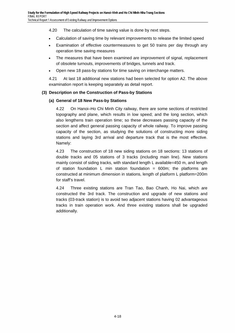
Study for the Formulation of High Speed Railway Projects on Hanoi–Vinh and Ho Chi Minh–Nha Trang Sections FINAL REPORT Technical Report 1 Assessment of Existing Railway and Improvement Options
4-18
4.20 The calculation of time saving value is done by next steps.
Calculation of saving time by relevant improvements to release the limited speed
Examination of effective countermeasures to get 50 trains per day through any operation time saving measures
The measures that have been examined are improvement of signal, replacement of obsolete turnouts, improvements of bridges, tunnels and track.
Open new 18 pass-by stations for time saving on interchange matters.
4.21 At last 18 additional new stations had been selected for option A2. The above examination report is keeping separately as detail report.
(3) Description on the Construction of Pass-by Stations
(a) General of 18 New Pass-by Stations
4.22 On Hanoi–Ho Chi Minh City railway, there are some sections of restricted topography and plane, which results in low speed; and the long section, which also lengthens train operation time; so these decreases passing capacity of the section and affect general passing capacity of whole railway. To improve passing capacity of the section, as studying the solutions of constructing more siding stations and laying 3rd arrival and departure track that is the most effective. Namely:
4.23 The construction of 18 new siding stations on 18 sections: 13 stations of double tracks and 05 stations of 3 tracks (including main line). New stations mainly consist of siding tracks, with standard length L available=450 m, and length of station foundation L min station foundation = 600m; the platforms are constructed at minimum dimension in stations, length of platform L platform=200m for staff’s travel.
4.24 Three existing stations are Tran Tao, Bao Chanh, Ho Nai, which are constructed the 3rd track. The construction and upgrade of new stations and tracks (03-track station) is to avoid two adjacent stations having 02 advantageous tracks in train operation work. And three existing stations shall be upgraded additionally.
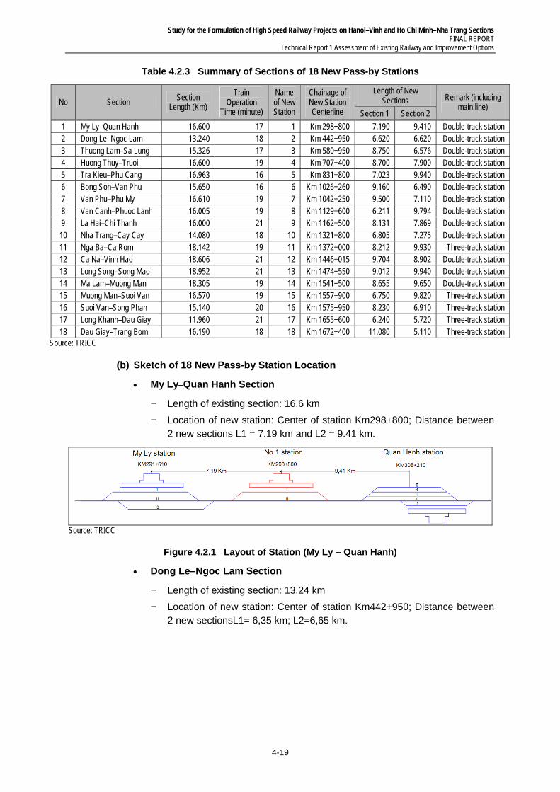
Study for the Formulation of High Speed Railway Projects on Hanoi–Vinh and Ho Chi Minh–Nha Trang Sections FINAL REPORT
Technical Report 1 Assessment of Existing Railway and Improvement Options
4-19
Table 4.2.3 Summary of Sections of 18 New Pass-by Stations
No Section Section
Length (Km)
Train Operation
Time (minute)
Name of New Station
Chainage of New Station Centerline
Length of New Sections Remark (including
main line) Section 1 Section 2
1 My Ly–Quan Hanh 16.600 17 1 Km 298+800 7.190 9.410 Double-track station 2 Dong Le–Ngoc Lam 13.240 18 2 Km 442+950 6.620 6.620 Double-track station 3 Thuong Lam–Sa Lung 15.326 17 3 Km 580+950 8.750 6.576 Double-track station 4 Huong Thuy–Truoi 16.600 19 4 Km 707+400 8.700 7.900 Double-track station 5 Tra Kieu–Phu Cang 16.963 16 5 Km 831+800 7.023 9.940 Double-track station 6 Bong Son–Van Phu 15.650 16 6 Km 1026+260 9.160 6.490 Double-track station 7 Van Phu–Phu My 16.610 19 7 Km 1042+250 9.500 7.110 Double-track station 8 Van Canh–Phuoc Lanh 16.005 19 8 Km 1129+600 6.211 9.794 Double-track station 9 La Hai–Chi Thanh 16.000 21 9 Km 1162+500 8.131 7.869 Double-track station
10 Nha Trang–Cay Cay 14.080 18 10 Km 1321+800 6.805 7.275 Double-track station 11 Nga Ba–Ca Rom 18.142 19 11 Km 1372+000 8.212 9.930 Three-track station 12 Ca Na–Vinh Hao 18.606 21 12 Km 1446+015 9.704 8.902 Double-track station 13 Long Song–Song Mao 18.952 21 13 Km 1474+550 9.012 9.940 Double-track station 14 Ma Lam–Muong Man 18.305 19 14 Km 1541+500 8.655 9.650 Double-track station 15 Muong Man–Suoi Van 16.570 19 15 Km 1557+900 6.750 9.820 Three-track station 16 Suoi Van–Song Phan 15.140 20 16 Km 1575+950 8.230 6.910 Three-track station 17 Long Khanh–Dau Giay 11.960 21 17 Km 1655+600 6.240 5.720 Three-track station 18 Dau Giay–Trang Bom 16.190 18 18 Km 1672+400 11.080 5.110 Three-track station
Source: TRICC
(b) Sketch of 18 New Pass-by Station Location
My Ly–Quan Hanh Section
− Length of existing section: 16.6 km
− Location of new station: Center of station Km298+800; Distance between 2 new sections L1 = 7.19 km and L2 = 9.41 km.
Source: TRICC
Figure 4.2.1 Layout of Station (My Ly – Quan Hanh)
Dong Le–Ngoc Lam Section
− Length of existing section: 13,24 km
− Location of new station: Center of station Km442+950; Distance between 2 new sectionsL1= 6,35 km; L2=6,65 km.
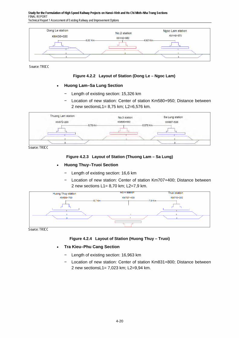
Study for the Formulation of High Speed Railway Projects on Hanoi–Vinh and Ho Chi Minh–Nha Trang Sections FINAL REPORT Technical Report 1 Assessment of Existing Railway and Improvement Options
4-20
Source: TRICC
Figure 4.2.2 Layout of Station (Dong Le – Ngoc Lam)
Huong Lam–Sa Lung Section
− Length of existing section: 15,326 km
− Location of new station: Center of station Km580+950; Distance between 2 new sectionsL1= 8,75 km; L2=6,576 km.
Source: TRICC
Figure 4.2.3 Layout of Station (Thuong Lam – Sa Lung)
Huong Thuy–Truoi Section
− Length of existing section: 16,6 km
− Location of new station: Center of station Km707+400; Distance between 2 new sections L1= 8,70 km; L2=7,9 km.
Source: TRICC
Figure 4.2.4 Layout of Station (Huong Thuy – Truoi)
Tra Kieu–Phu Cang Section
− Length of existing section: 16,963 km
− Location of new station: Center of station Km831+800; Distance between 2 new sectionsL1= 7,023 km; L2=9,94 km.
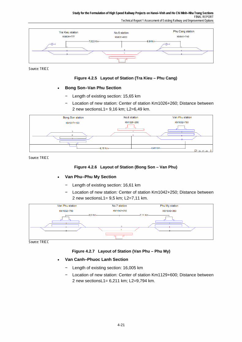
Study for the Formulation of High Speed Railway Projects on Hanoi–Vinh and Ho Chi Minh–Nha Trang Sections FINAL REPORT
Technical Report 1 Assessment of Existing Railway and Improvement Options
4-21
Source: TRICC
Figure 4.2.5 Layout of Station (Tra Kieu – Phu Cang)
Bong Son–Van Phu Section
− Length of existing section: 15,65 km
− Location of new station: Center of station Km1026+260; Distance between 2 new sectionsL1= 9,16 km; L2=6,49 km.
Source: TRICC
Figure 4.2.6 Layout of Station (Bong Son – Van Phu)
Van Phu–Phu My Section
− Length of existing section: 16,61 km
− Location of new station: Center of station Km1042+250; Distance between 2 new sectionsL1= 9,5 km; L2=7,11 km.
Source: TRICC
Figure 4.2.7 Layout of Station (Van Phu – Phu My)
Van Canh–Phuoc Lanh Section
− Length of existing section: 16,005 km
− Location of new station: Center of station Km1129+600; Distance between 2 new sectionsL1= 6,211 km; L2=9,794 km.
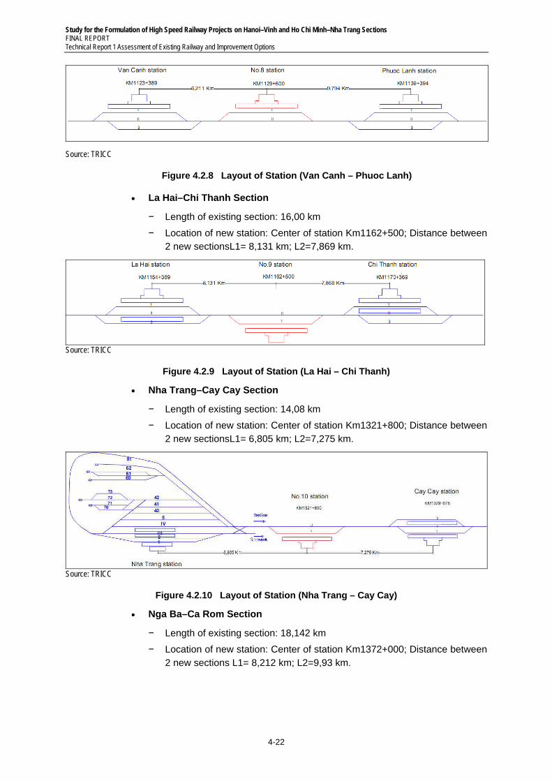
Study for the Formulation of High Speed Railway Projects on Hanoi–Vinh and Ho Chi Minh–Nha Trang Sections FINAL REPORT Technical Report 1 Assessment of Existing Railway and Improvement Options
4-22
Source: TRICC
Figure 4.2.8 Layout of Station (Van Canh – Phuoc Lanh)
La Hai–Chi Thanh Section
− Length of existing section: 16,00 km
− Location of new station: Center of station Km1162+500; Distance between 2 new sectionsL1= 8,131 km; L2=7,869 km.
Source: TRICC
Figure 4.2.9 Layout of Station (La Hai – Chi Thanh)
Nha Trang–Cay Cay Section
− Length of existing section: 14,08 km
− Location of new station: Center of station Km1321+800; Distance between 2 new sectionsL1= 6,805 km; L2=7,275 km.
Source: TRICC
Figure 4.2.10 Layout of Station (Nha Trang – Cay Cay)
Nga Ba–Ca Rom Section
− Length of existing section: 18,142 km
− Location of new station: Center of station Km1372+000; Distance between 2 new sections L1= 8,212 km; L2=9,93 km.
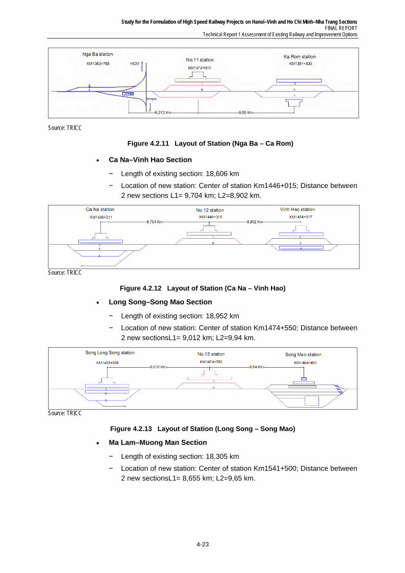
Study for the Formulation of High Speed Railway Projects on Hanoi–Vinh and Ho Chi Minh–Nha Trang Sections FINAL REPORT
Technical Report 1 Assessment of Existing Railway and Improvement Options
4-23
Source: TRICC
Figure 4.2.11 Layout of Station (Nga Ba – Ca Rom)
Ca Na–Vinh Hao Section
− Length of existing section: 18,606 km
− Location of new station: Center of station Km1446+015; Distance between 2 new sections L1= 9,704 km; L2=8,902 km.
Source: TRICC
Figure 4.2.12 Layout of Station (Ca Na – Vinh Hao)
Long Song–Song Mao Section
− Length of existing section: 18,952 km
− Location of new station: Center of station Km1474+550; Distance between 2 new sectionsL1= 9,012 km; L2=9,94 km.
Source: TRICC
Figure 4.2.13 Layout of Station (Long Song – Song Mao)
Ma Lam–Muong Man Section
− Length of existing section: 18,305 km
− Location of new station: Center of station Km1541+500; Distance between 2 new sectionsL1= 8,655 km; L2=9,65 km.
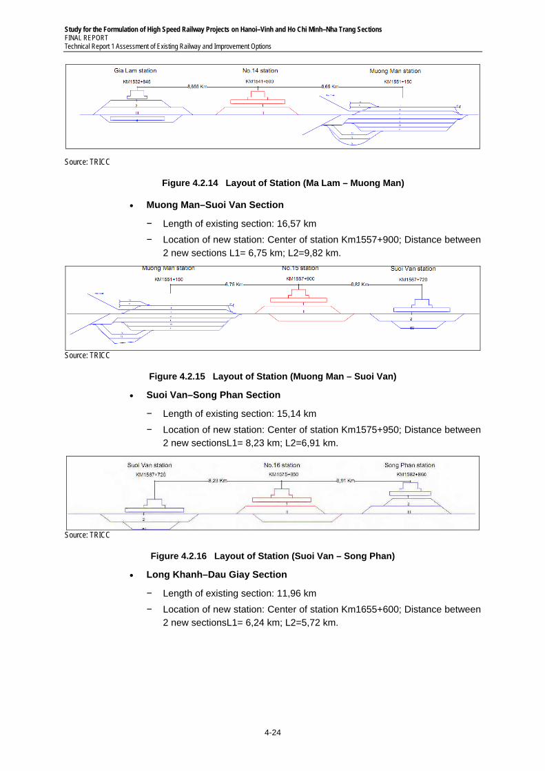
Study for the Formulation of High Speed Railway Projects on Hanoi–Vinh and Ho Chi Minh–Nha Trang Sections FINAL REPORT Technical Report 1 Assessment of Existing Railway and Improvement Options
4-24
Source: TRICC
Figure 4.2.14 Layout of Station (Ma Lam – Muong Man)
Muong Man–Suoi Van Section
− Length of existing section: 16,57 km
− Location of new station: Center of station Km1557+900; Distance between 2 new sections L1= 6,75 km; L2=9,82 km.
Source: TRICC
Figure 4.2.15 Layout of Station (Muong Man – Suoi Van)
Suoi Van–Song Phan Section
− Length of existing section: 15,14 km
− Location of new station: Center of station Km1575+950; Distance between 2 new sectionsL1= 8,23 km; L2=6,91 km.
Source: TRICC
Figure 4.2.16 Layout of Station (Suoi Van – Song Phan)
Long Khanh–Dau Giay Section
− Length of existing section: 11,96 km
− Location of new station: Center of station Km1655+600; Distance between 2 new sectionsL1= 6,24 km; L2=5,72 km.
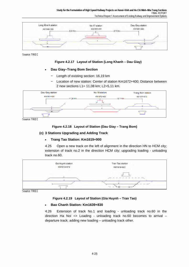
Study for the Formulation of High Speed Railway Projects on Hanoi–Vinh and Ho Chi Minh–Nha Trang Sections FINAL REPORT
Technical Report 1 Assessment of Existing Railway and Improvement Options
4-25
Source: TRICC
Figure 4.2.17 Layout of Station (Long Khanh – Dau Giay)
Dau Giay–Trang Bom Section
− Length of existing section: 16,19 km
− Location of new station: Center of station Km1672+400; Distance between 2 new sections L1= 11,08 km; L2=5,11 km.
Source: TRICC
Figure 4.2.18 Layout of Station (Dau Giay – Trang Bom)
(c) 3 Stations Upgrading and Adding Track
Trang Tao Station: Km1619+900
4.25 Open a new track on the left of alignment in the direction HN to HCM city; extension of track no.2 in the direction HCM city; upgrading loading - unloading track no.60.
Source: TRICC
Figure 4.2.19 Layout of Station (Gia Huynh – Tran Tao)
Bao Chanh Station: Km1639+830
4.26 Extension of track No.1 and loading - unloading track no.60 in the direction Ha Noi => Loading - unloading track no.60 becomes to arrival – departure track; adding new loading – unloading track other.
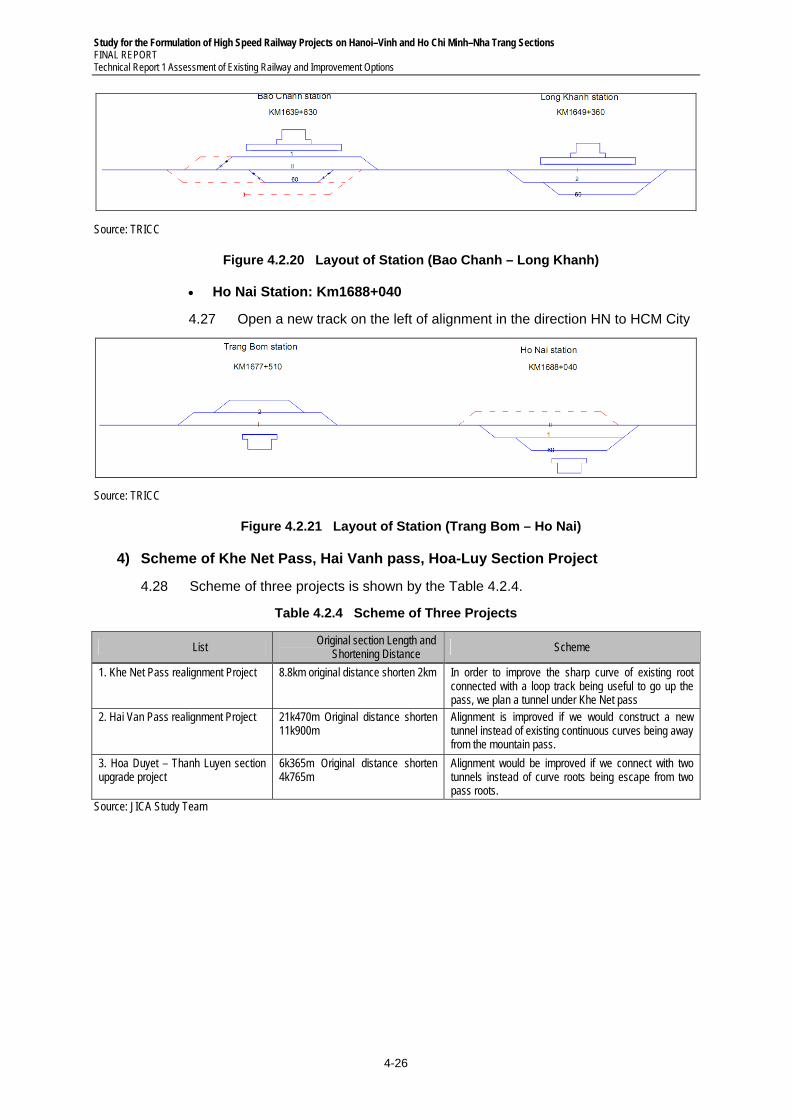
Study for the Formulation of High Speed Railway Projects on Hanoi–Vinh and Ho Chi Minh–Nha Trang Sections FINAL REPORT Technical Report 1 Assessment of Existing Railway and Improvement Options
4-26
Source: TRICC
Figure 4.2.20 Layout of Station (Bao Chanh – Long Khanh)
Ho Nai Station: Km1688+040
4.27 Open a new track on the left of alignment in the direction HN to HCM City
Source: TRICC
Figure 4.2.21 Layout of Station (Trang Bom – Ho Nai)
4) Scheme of Khe Net Pass, Hai Vanh pass, Hoa-Luy Section Project
4.28 Scheme of three projects is shown by the Table 4.2.4.
Table 4.2.4 Scheme of Three Projects
List Original section Length and
Shortening Distance Scheme
1. Khe Net Pass realignment Project 8.8km original distance shorten 2km In order to improve the sharp curve of existing root connected with a loop track being useful to go up the pass, we plan a tunnel under Khe Net pass
2. Hai Van Pass realignment Project 21k470m Original distance shorten 11k900m
Alignment is improved if we would construct a new tunnel instead of existing continuous curves being away from the mountain pass.
3. Hoa Duyet – Thanh Luyen section upgrade project
6k365m Original distance shorten 4k765m
Alignment would be improved if we connect with two tunnels instead of curve roots being escape from two pass roots.
Source: JICA Study Team
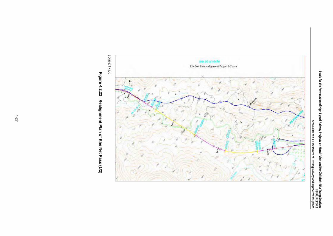
Study for the Formulation of H
igh Speed Railw
ay Projects on Hanoi–Vinh and H
o Chi M
inh–Nha Trang Sections
FINAL R
EPOR
T Technical R
eport 1 Assessment of Existing R
ailway and Im
provement O
ptions
4-27
Source: TRIC
C
Fig
ure 4.2.22 R
ealign
men
t Plan
of K
he N
et Pass (1/2)
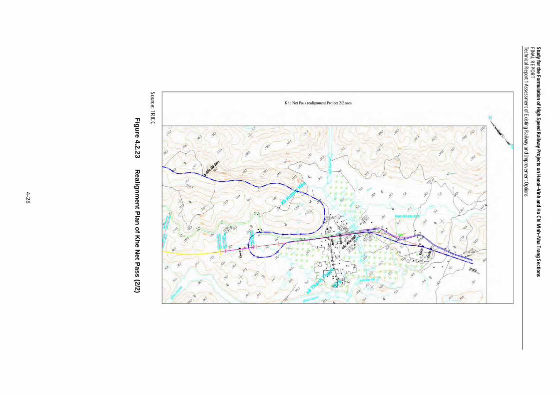
Study for the Formulation of H
igh Speed Railw
ay Projects on Hanoi–Vinh and H
o Chi M
inh–Nha Trang Sections
FINAL R
EPOR
T Technical R
eport 1 Assessment of Existing R
ailway and Im
provement O
ptions
4-28
Source: TRIC
C
Fig
ure 4.2.23 R
ealign
men
t Plan
of K
he N
et Pass (2/2)
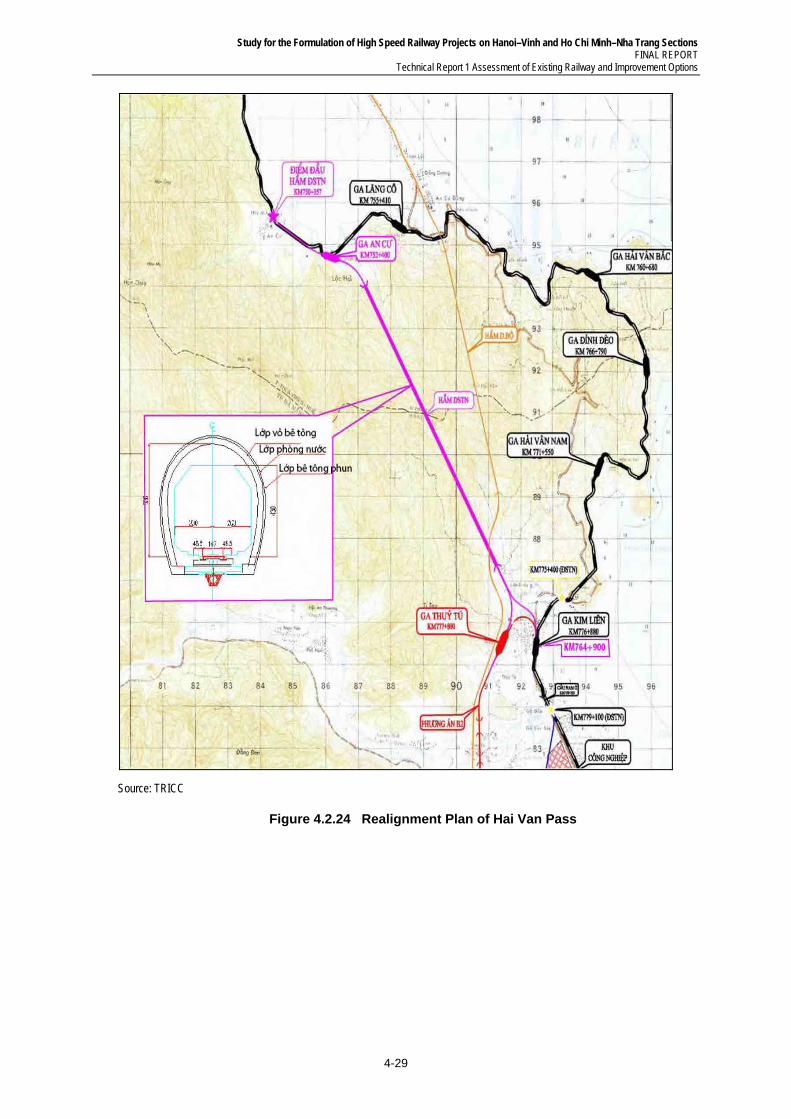
Study for the Formulation of High Speed Railway Projects on Hanoi–Vinh and Ho Chi Minh–Nha Trang Sections FINAL REPORT
Technical Report 1 Assessment of Existing Railway and Improvement Options
4-29
Source: TRICC
Figure 4.2.24 Realignment Plan of Hai Van Pass
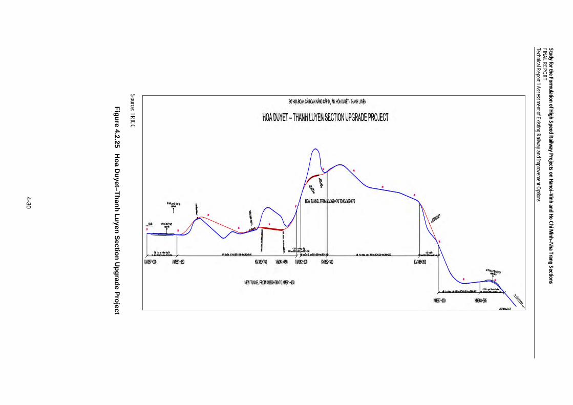
Study for the Formulation of H
igh Speed Railw
ay Projects on Hanoi–Vinh and H
o Chi M
inh–Nha Trang Sections
FINAL R
EPOR
T Technical R
eport 1 Assessment of Existing R
ailway and Im
provement O
ptions
4-30
Source: TRIC
C
Fig
ure 4.2.25 H
oa D
uyet–T
han
h L
uyen
Sectio
n U
pg
rade P
roject
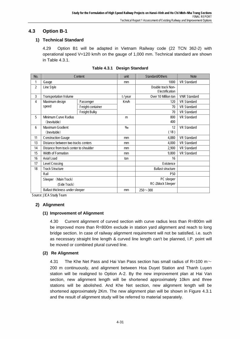
Study for the Formulation of High Speed Railway Projects on Hanoi–Vinh and Ho Chi Minh–Nha Trang Sections FINAL REPORT
Technical Report 1 Assessment of Existing Railway and Improvement Options
4-31
4.3 Option B-1
1) Technical Standard
4.29 Option B1 will be adapted in Vietnam Railway code (22 TCN 362-2) with operational speed V=120 km/h on the gauge of 1,000 mm. Technical standard are shown in Table 4.3.1.
Table 4.3.1 Design Standard
No. Content unit Standard/Others Note
1 Gauge mm 1000 VR Standard 2 Line Style Double track Non-
Electrification
3 Transportation Volume t / year Over 10 Million ton VNR Standard 4 Maximum design
speed Passenger Km/h 120 VR Standard Freight container 70 VR Standard Freight Bulky 70 VR Standard
5 Minimum Curve Radius (Inevitable)
m 800 400
VR Standard
6 Maximum Gradient (Inevitable)
‰ 12 ( 18 )
VR Standard
11 Construction Gauge mm 4,880 VR Standard 13 Distance between two tracks centers mm 4,000 VR Standard 14 Distance from track center to shoulder mm 2,900 VR Standard 15 Width of Formation mm 9,800 VR Standard 16 Axial Load ton 16 17 Level Crossing Existence 18 Track Structure Ballast structure
Rail P50
Sleeper(Main Track) (Side Track)
PC sleeper RC-2block Sleeper
Ballast thickness under sleeper mm 250~300
Source: JICA Study Team
2) Alignment
(1) Improvement of Alignment
4.30 Current alignment of curved section with curve radius less than R=800m will be improved more than R=800m exclude in station yard alignment and reach to long bridge section. In case of railway alignment requirement will not be satisfied, i.e. such as necessary straight line length & curved line length can't be planned, I.P. point will be moved or combined plural curved line.
(2) Re Alignment
4.31 The Khe Net Pass and Hai Van Pass section has small radius of R=100 m~
200 m continuously, and alignment between Hoa Duyet Station and Thanh Luyen station will be realigned to Option A-2. By the new improvement plan at Hai Van section, new alignment length will be shortened approximately 10km and three stations will be abolished. And Khe Net section, new alignment length will be shortened approximately 2Km. The new alignment plan will be shown in Figure 4.3.1 and the result of alignment study will be referred to material separately.
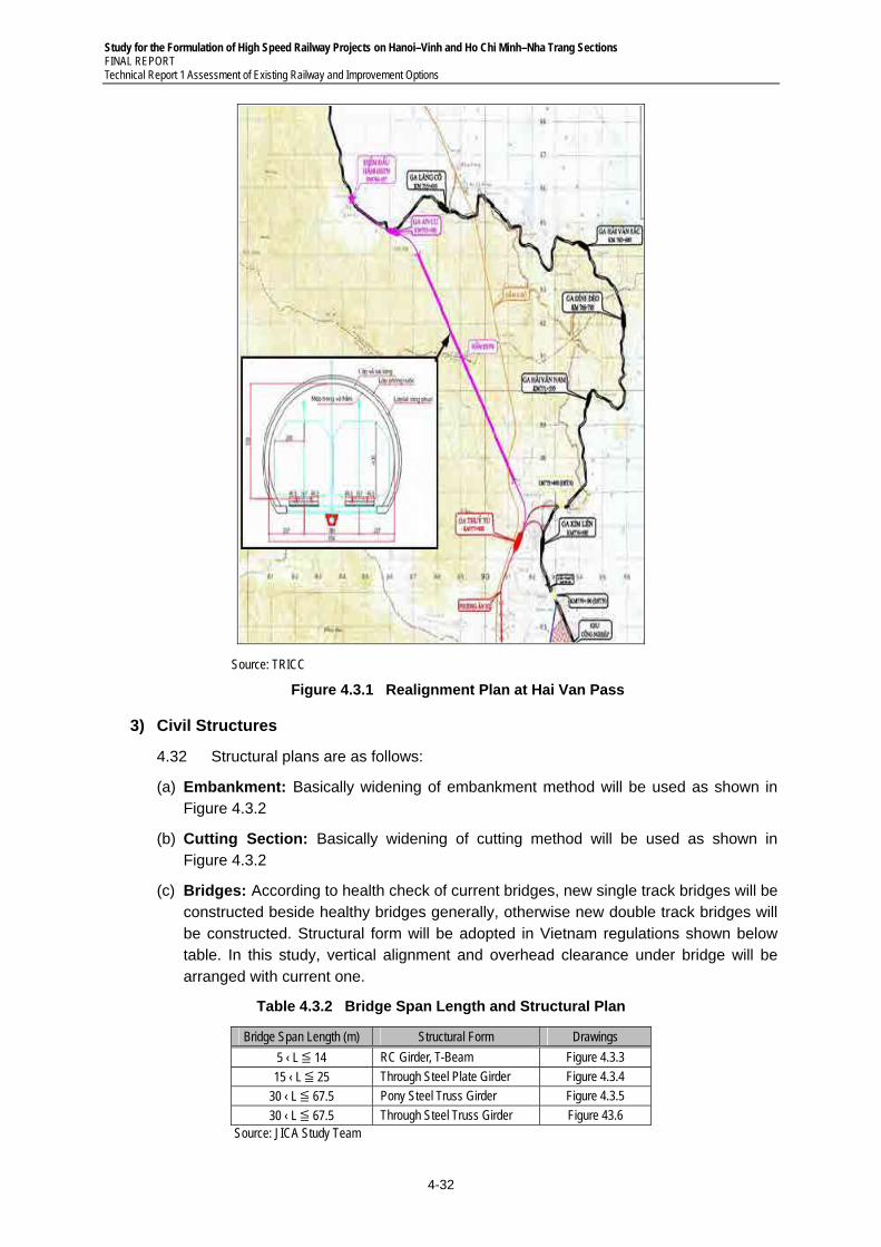
Study for the Formulation of High Speed Railway Projects on Hanoi–Vinh and Ho Chi Minh–Nha Trang Sections FINAL REPORT Technical Report 1 Assessment of Existing Railway and Improvement Options
4-32
Source: TRICC
Figure 4.3.1 Realignment Plan at Hai Van Pass
3) Civil Structures
4.32 Structural plans are as follows:
(a) Embankment: Basically widening of embankment method will be used as shown in Figure 4.3.2
(b) Cutting Section: Basically widening of cutting method will be used as shown in Figure 4.3.2
(c) Bridges: According to health check of current bridges, new single track bridges will be constructed beside healthy bridges generally, otherwise new double track bridges will be constructed. Structural form will be adopted in Vietnam regulations shown below table. In this study, vertical alignment and overhead clearance under bridge will be arranged with current one.
Table 4.3.2 Bridge Span Length and Structural Plan
Bridge Span Length (m) Structural Form Drawings
5 ‹ L ≦ 14 RC Girder, T-Beam Figure 4.3.3
15 ‹ L ≦ 25 Through Steel Plate Girder Figure 4.3.4
30 ‹ L ≦ 67.5 Pony Steel Truss Girder Figure 4.3.5
30 ‹ L ≦ 67.5 Through Steel Truss Girder Figure 43.6 Source: JICA Study Team
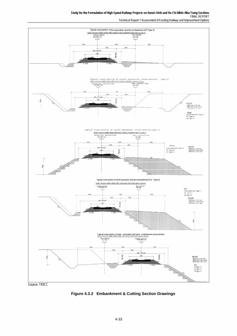
Study for the Formulation of High Speed Railway Projects on Hanoi–Vinh and Ho Chi Minh–Nha Trang Sections FINAL REPORT
Technical Report 1 Assessment of Existing Railway and Improvement Options
4-33
Source: TRICC
Figure 4.3.2 Embankment & Cutting Section Drawings
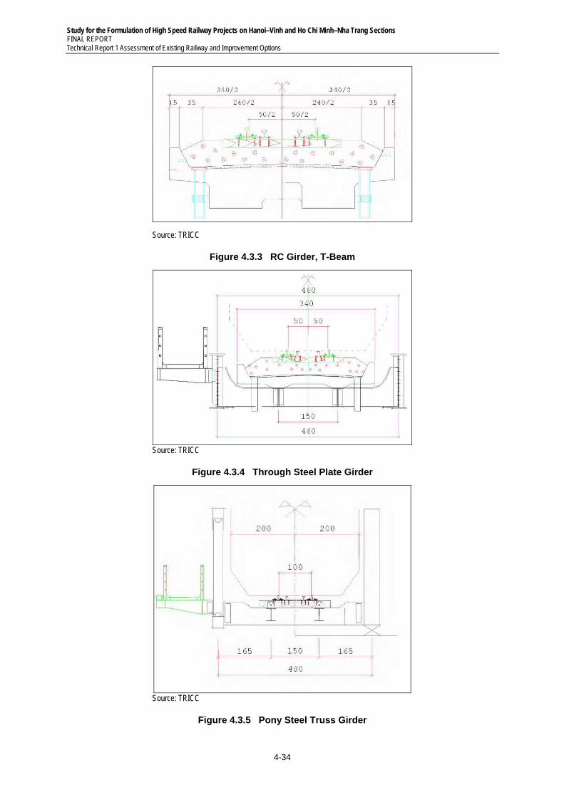
Study for the Formulation of High Speed Railway Projects on Hanoi–Vinh and Ho Chi Minh–Nha Trang Sections FINAL REPORT Technical Report 1 Assessment of Existing Railway and Improvement Options
4-34
Source: TRICC
Figure 4.3.3 RC Girder, T-Beam
Source: TRICC
Figure 4.3.4 Through Steel Plate Girder
Source: TRICC
Figure 4.3.5 Pony Steel Truss Girder
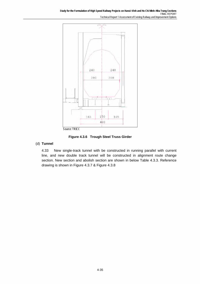
Study for the Formulation of High Speed Railway Projects on Hanoi–Vinh and Ho Chi Minh–Nha Trang Sections FINAL REPORT
Technical Report 1 Assessment of Existing Railway and Improvement Options
4-35
Source: TRICC
Figure 4.3.6 Trough Steel Truss Girder
(d) Tunnel
4.33 New single-track tunnel with be constructed in running parallel with current line, and new double track tunnel will be constructed in alignment route change section. New section and abolish section are shown in below Table 4.3.3. Reference drawing is shown in Figure 4.3.7 & Figure 4.3.8
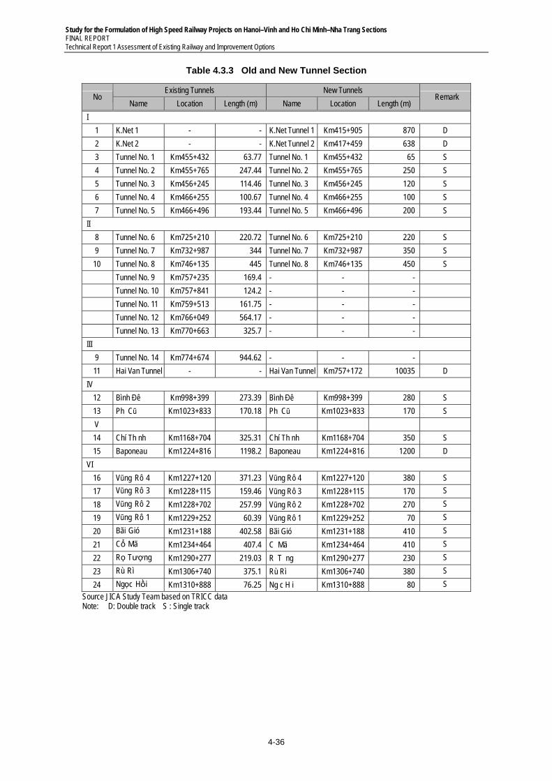
Study for the Formulation of High Speed Railway Projects on Hanoi–Vinh and Ho Chi Minh–Nha Trang Sections FINAL REPORT Technical Report 1 Assessment of Existing Railway and Improvement Options
4-36
Table 4.3.3 Old and New Tunnel Section
No Existing Tunnels New Tunnels
Remark Name Location Length (m) Name Location Length (m)
I
1 K.Net 1 - - K.Net Tunnel 1 Km415+905 870 D
2 K.Net 2 - - K.Net Tunnel 2 Km417+459 638 D
3 Tunnel No. 1 Km455+432 63.77 Tunnel No. 1 Km455+432 65 S
4 Tunnel No. 2 Km455+765 247.44 Tunnel No. 2 Km455+765 250 S
5 Tunnel No. 3 Km456+245 114.46 Tunnel No. 3 Km456+245 120 S
6 Tunnel No. 4 Km466+255 100.67 Tunnel No. 4 Km466+255 100 S
7 Tunnel No. 5 Km466+496 193.44 Tunnel No. 5 Km466+496 200 S
II
8 Tunnel No. 6 Km725+210 220.72 Tunnel No. 6 Km725+210 220 S
9 Tunnel No. 7 Km732+987 344 Tunnel No. 7 Km732+987 350 S
10 Tunnel No. 8 Km746+135 445 Tunnel No. 8 Km746+135 450 S
Tunnel No. 9 Km757+235 169.4 - - -
Tunnel No. 10 Km757+841 124.2 - - -
Tunnel No. 11 Km759+513 161.75 - - -
Tunnel No. 12 Km766+049 564.17 - - -
Tunnel No. 13 Km770+663 325.7 - - -
III
9 Tunnel No. 14 Km774+674 944.62 - - -
11 Hai Van Tunnel - - Hai Van Tunnel Km757+172 10035 D
IV
12 Bình Đê Km998+399 273.39 Bình Đê Km998+399 280 S
13 Ph� Cũ Km1023+833 170.18 Ph� Cũ Km1023+833 170 S
V
14 Chí Th�nh Km1168+704 325.31 Chí Th�nh Km1168+704 350 S
15 Baponeau Km1224+816 1198.2 Baponeau Km1224+816 1200 D
VI
16 Vũng Rô 4 Km1227+120 371.23 Vũng Rô 4 Km1227+120 380 S
17 Vũng Rô 3 Km1228+115 159.46 Vũng Rô 3 Km1228+115 170 S
18 Vũng Rô 2 Km1228+702 257.99 Vũng Rô 2 Km1228+702 270 S
19 Vũng Rô 1 Km1229+252 60.39 Vũng Rô 1 Km1229+252 70 S
20 Bãi Gió Km1231+188 402.58 Bãi Gió Km1231+188 410 S
21 Cổ Mã Km1234+464 407.4 C� Mã Km1234+464 410 S
22 Rọ Tượng Km1290+277 219.03 R� T��ng Km1290+277 230 S
23 Rù Rì Km1306+740 375.1 Rù Rì Km1306+740 380 S
24 Ngọc Hồi Km1310+888 76.25 Ng�c H�i Km1310+888 80 S
Source JICA Study Team based on TRICC data Note: D: Double track S : Single track
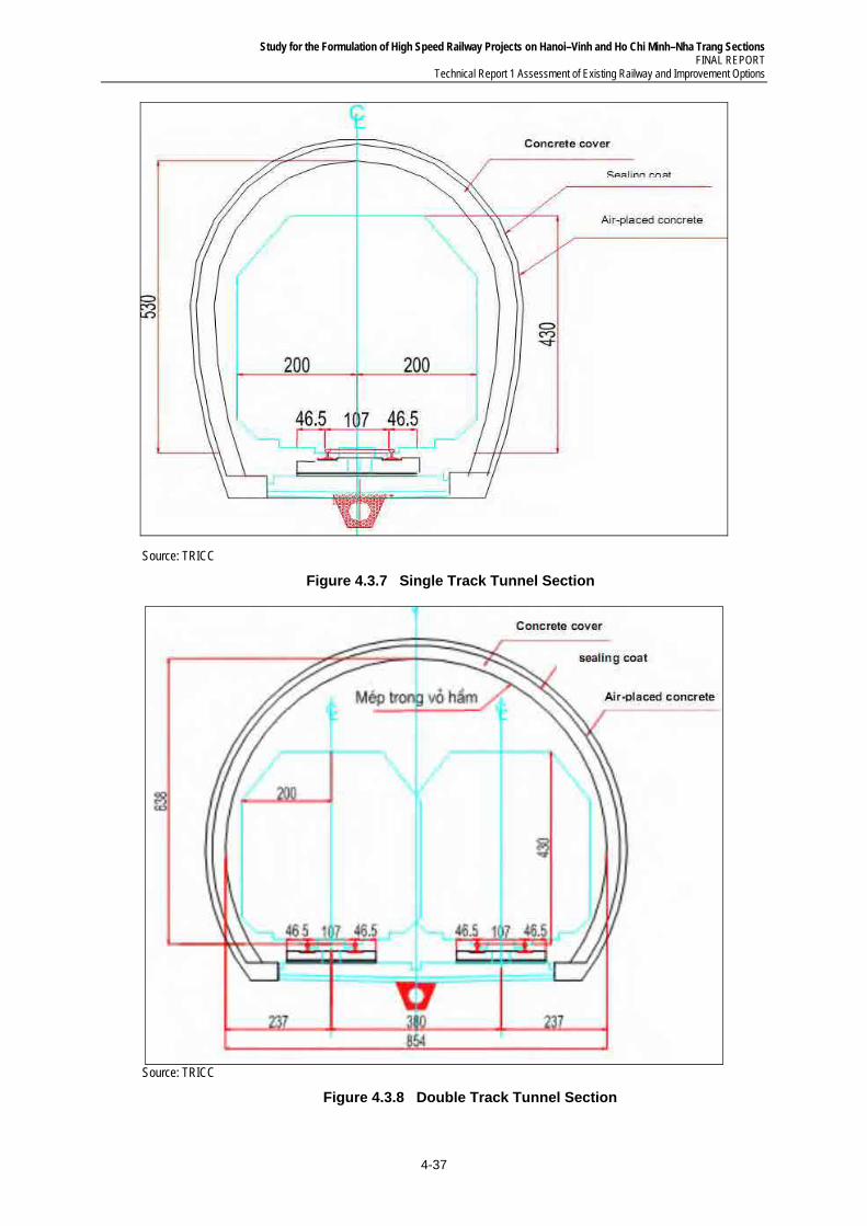
Study for the Formulation of High Speed Railway Projects on Hanoi–Vinh and Ho Chi Minh–Nha Trang Sections FINAL REPORT
Technical Report 1 Assessment of Existing Railway and Improvement Options
4-37
Source: TRICC
Figure 4.3.7 Single Track Tunnel Section
Source: TRICC
Figure 4.3.8 Double Track Tunnel Section
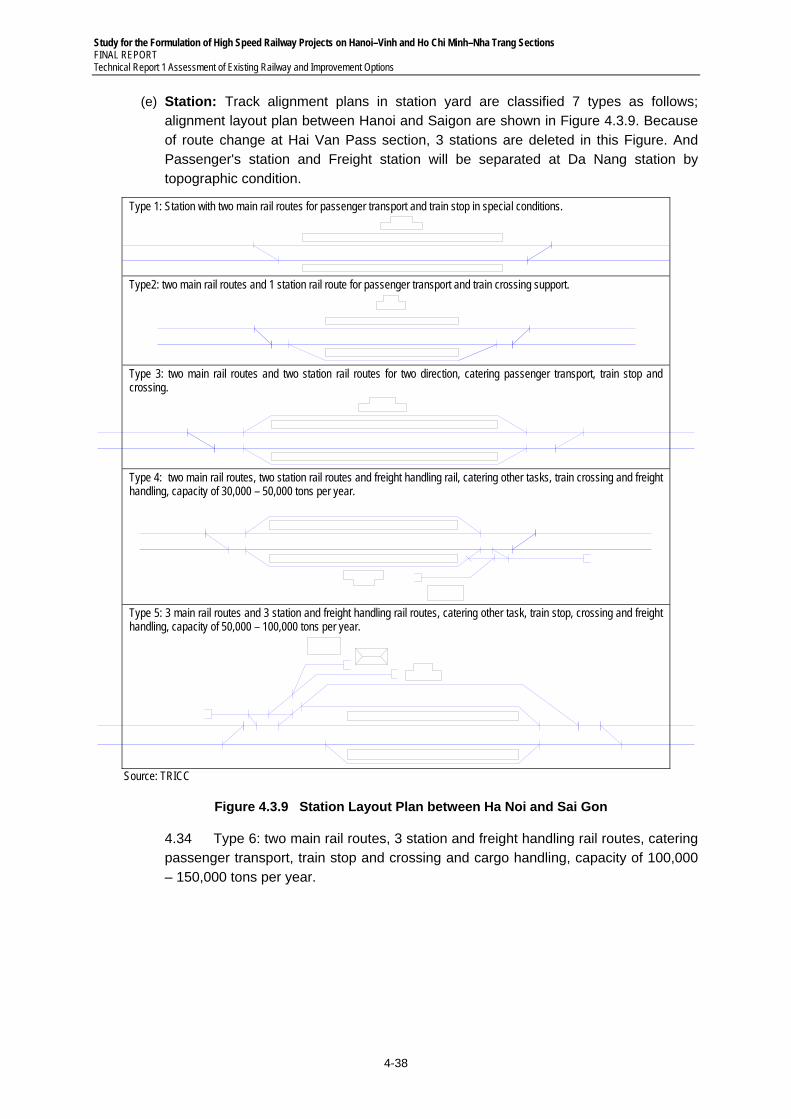
Study for the Formulation of High Speed Railway Projects on Hanoi–Vinh and Ho Chi Minh–Nha Trang Sections FINAL REPORT Technical Report 1 Assessment of Existing Railway and Improvement Options
4-38
(e) Station: Track alignment plans in station yard are classified 7 types as follows; alignment layout plan between Hanoi and Saigon are shown in Figure 4.3.9. Because of route change at Hai Van Pass section, 3 stations are deleted in this Figure. And Passenger's station and Freight station will be separated at Da Nang station by topographic condition.
Type 1: Station with two main rail routes for passenger transport and train stop in special conditions.
Type2: two main rail routes and 1 station rail route for passenger transport and train crossing support.
Type 3: two main rail routes and two station rail routes for two direction, catering passenger transport, train stop and crossing.
Type 4: two main rail routes, two station rail routes and freight handling rail, catering other tasks, train crossing and freight handling, capacity of 30,000 – 50,000 tons per year.
Type 5: 3 main rail routes and 3 station and freight handling rail routes, catering other task, train stop, crossing and freight handling, capacity of 50,000 – 100,000 tons per year.
Source: TRICC
Figure 4.3.9 Station Layout Plan between Ha Noi and Sai Gon
4.34 Type 6: two main rail routes, 3 station and freight handling rail routes, catering passenger transport, train stop and crossing and cargo handling, capacity of 100,000 – 150,000 tons per year.
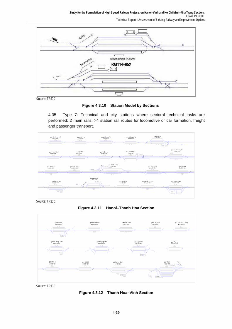
Study for the Formulation of High Speed Railway Projects on Hanoi–Vinh and Ho Chi Minh–Nha Trang Sections FINAL REPORT
Technical Report 1 Assessment of Existing Railway and Improvement Options
4-39
Source: TRICC
Figure 4.3.10 Station Model by Sections
4.35 Type 7: Technical and city stations where sectoral technical tasks are performed: 2 main rails, >4 station rail routes for locomotive or car formation, freight and passenger transport.
g a t h - ê n g t Ýnk m17+450
TX®M
c ¶n g
XM An to µn
g a c h î t Ýak m25+500
g a ph ó x u y ª nk m33+658
g a ®å n g v ¨ nk m44+672
g a ph ñ l ýk m55+862
g a b×n h l ô ck m66+546
g a c Çu h äk m72+914
g a § Æn g x ¸k m81+000
g a Nam § Þn hk m86+767
g a t r ×n h x u y ª nk m93+340
g a Nin h b×n hk m114+652 g a c Çu y ª n
k m120+350g a g h Òn hk m125+040
g a C¸ t ®»n gk m107+625
g a Nó i g « ik m100+805
g a ®å n g g iaok m133+740
g a BØm s ¬ nk m141+477
g a ®ß l Ì nk m152+300
g a n g h Üa t r an gk m161+000
g a t h an h h ã ak m175+231
Source: TRICC
Figure 4.3.11 Hanoi–Thanh Hoa Section
g a Yª n t h ¸ ik m187+470
g a min h k h « ik m196+900
g a t h Þ l o n gk m207+070
g a v ¨ n t r a ik m218+900
g a Kh o a t r - ê n gk m228+950
g a t r - ê n g L©mk m237+798
g a Ho µn g Maik m245+450
g a CÇu Gi¸ tk m260+960
g a Yª n Lýk m271+600
To a x e
x .k h ¸ c h
H.t r - ê n g
§ .M¸ y
g a Ch î s ik m279+000
g a Mü Lýk m291+610
g a Qu ¸ n Hµn hk m308+210
g a Vin hk m319+020
Source: TRICC
Figure 4.3.12 Thanh Hoa–Vinh Section
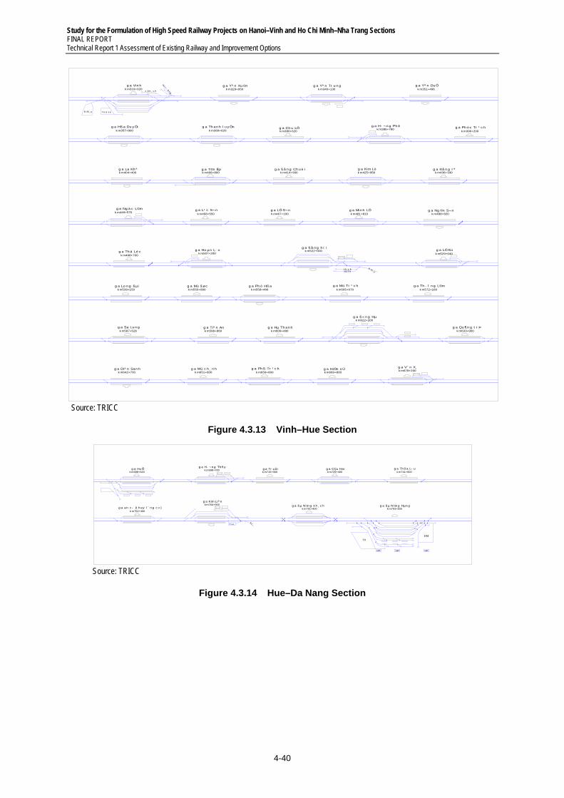
Study for the Formulation of High Speed Railway Projects on Hanoi–Vinh and Ho Chi Minh–Nha Trang Sections FINAL REPORT Technical Report 1 Assessment of Existing Railway and Improvement Options
4-40
To a x e
x .k h ¸ c h
H.t r -
êng
§ .M¸ y
g a Vin hk m319+020
g a Yª n Xu ©nk m329+950
g a Th an h l u y Önk m369+620
g a Hß a Du y Ötk m357+800
g a Yª n Du Ök m351+496
g a Yª n Tr u n gk m340+130
g a Ch u LÔk m380+620
g a H- ¬ n g Ph èk m386+780
g a Ph ó c Tr ¹ c hk m396+200
g a La Kh ªk m404+400
g a T©n Êpk m408+800
g a § å n g Ch u è ik m414+930
g a Kim Lòk m425+958
g a ®å n g l ªk m436+330
g a Ng ä c L©mk m449+570
g a L¹ c S¬ nk m458+550
g a LÖ S¬ nk m467+100
g a Min h LÖk m481+810
g a Ng ©n S¬ nk m488+820
g a Th ä Lé ck m498+700
g a Ho µn L· ok m507+200
t k x kSCTX
§ m¸ y
g a § å n g h í ik m522+000 g a LÖ Kú
k m529+040
g a Lo n g § µik m539+150
g a Mü § øck m550+890
g a Tiª n Ank m598+860
g a Sa Lu n gk m587+526
g a Th - î n g L©mk m572+160
g a Mü Tr ¹ c hk m565+070
g a Ph ó Hß ak m558+466
g a Mü c h ¸ n hk m651+600
g a Diª n San hk m642+700
g a Qu ¶n g t r Þk m633+900
g a § « n g Hµk m622+200
g a Hµ Th an hk m609+480
g a Ph ß Tr ¹ c hk m659+800
g a HiÒn s Ük m669+800
g a V¨ n X¸k m678+200
Source: TRICC
Figure 4.3.13 Vinh–Hue Section
T.x e
V.t -
TX
ÐM
VP
g a Hu Õk m688+320
g a H- ¬ n g Th ñ yk m698+700 g a Tr u å i
k m715+300g a CÇu Haik m729+400
g a Th õ a L- uk m741+600
g a an c - (t h ay l ¨ n g c « )k m752+400
g a Kim Liª nk m764+900 g a § µ N½n g k h ¸ c h
k m791+400g a § µ N½n g Hµn g
k m793+500
VP VP
Source: TRICC
Figure 4.3.14 Hue–Da Nang Section
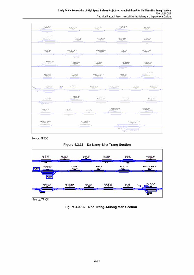
Study for the Formulation of High Speed Railway Projects on Hanoi–Vinh and Ho Chi Minh–Nha Trang Sections FINAL REPORT
Technical Report 1 Assessment of Existing Railway and Improvement Options
4-41
QuyNhon
XM
ÐM HT
ÐM
TX
g a LÖ Tr ¹ c hk m804+110 g a N« n g S¬ n
k m813+630g a Tr µ KiÖu
k m824+777
g a Nó i Th µn hk m890+420
g a Diª m Ph æk m879+420
g a Tam Kúk m864+670
g a AN Mük m857+100
g a Ph ó Can gk m841+740
g a Mé § øck m948+900
g a Hß a Vin h T©yk m940+420
g a Qu ¶n g Ng · ik m927+930
g a § ¹ i Lé ck m919+520
g a B×n h S¬ nk m909+050
g a Tr Þ B×n hk m901+050
g a Th ¹ c h Tr ôk m958+700
g a § øc Ph æk m967+680 g a t h ñ y Th ¹ c h
k m977+100g a SA Hu ún h
k m990+820g a Tam Qu an
k m1004+270
g a v ¹ n ph ók m1032+750
g a Bå n g s ¬ nk m1017+100
g a Ph ï Mük m1049+360
g a Kh ¸ n h ph - í ck m1060+290
g a Ph ï c ¸ tk m1070+860
g a B×n h ®Þn hk m1084+610
g a La Haik m1154+369
g a Ch Ý t h ¹ n hk m1170+396
g a Ph - í c L· n hk m1139+394
g a V©n c an hk m1123+389
g a T©n Vin hk m1110+806
g a Diª u t r ×k m1095+540
g a Ph ó HiÖpk m1210+825
g a H¶o S¬ nk m1220+142
g a § « n g t ¸ ck m1202+057
g a Tu y Hß ak m1197+557
g a Hß a § ak m1183+919
g a § ¹ i L· n hk m1232+221
g a Tu B« n gk m1241+993
g a Gi·k m1254+053
g a Hß a Hu y n hk m1269+442
g a Nin h Hß ak m1280+563
g a ph o n g t h ¹ n hk m1287+275
g a L- ¬ n g s ¬ nk m1302+977
g a Nh a Tr an g (m?i)k m1314+995
Source: TRICC
Figure 4.3.15 Da Nang–Nha Trang Section
Source: TRICC
Figure 4.3.16 Nha Trang–Muong Man Section
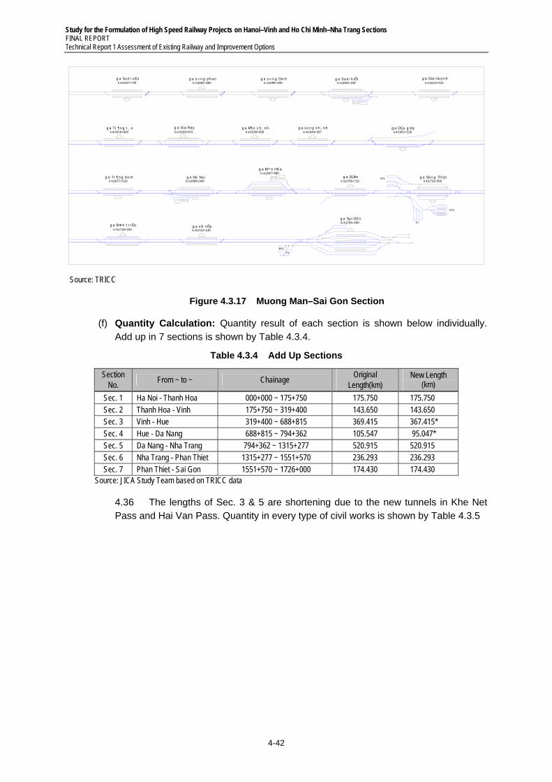
Study for the Formulation of High Speed Railway Projects on Hanoi–Vinh and Ho Chi Minh–Nha Trang Sections FINAL REPORT Technical Report 1 Assessment of Existing Railway and Improvement Options
4-42
HT1
HT2
TX
TX
ÐM
g a Su è i v Ënk m1567+720
g a s « n g ph ank m1582+860
g a B¶ o c h ¸ n hk m1639+830
g a Gia Rayk m1630+870
g a Tr ¶n g t ¸ ok m1619+900
g a Gia Hu y n hk m1613+510
g a Su è i k iÕtk m1603+100
g a s « n g Din hk m1595+930
g a Lo n g k h ¸ n hk m1649+367
g a DÇu g i©yk m1661+320
g a Tr ¶ n g bo mk m1677+510
g a Hè Naik m1688+040
g a Biª n Hß ak m1697+480
g a DÜ Ank m1706+710
g a Sã n g Th Çnk m1710+560
g a B×n h t r iÖuk m1718+340
g a v ß v Êpk m1722+130
g a Sµi Gß nk m1726+200
Source: TRICC
Figure 4.3.17 Muong Man–Sai Gon Section
(f) Quantity Calculation: Quantity result of each section is shown below individually. Add up in 7 sections is shown by Table 4.3.4.
Table 4.3.4 Add Up Sections
Section No.
From ~ to ~ Chainage Original
Length(km) New Length
(km)
Sec. 1 Ha Noi - Thanh Hoa 000+000 ~ 175+750 175.750 175.750 Sec. 2 Thanh Hoa - Vinh 175+750 ~ 319+400 143.650 143.650 Sec. 3 Vinh - Hue 319+400 ~ 688+815 369.415 367.415* Sec. 4 Hue - Da Nang 688+815 ~ 794+362 105.547 95.047* Sec. 5 Da Nang - Nha Trang 794+362 ~ 1315+277 520.915 520.915 Sec. 6 Nha Trang - Phan Thiet 1315+277 ~ 1551+570 236.293 236.293 Sec. 7 Phan Thiet - Sai Gon 1551+570 ~ 1726+000 174.430 174.430
Source: JICA Study Team based on TRICC data
4.36 The lengths of Sec. 3 & 5 are shortening due to the new tunnels in Khe Net Pass and Hai Van Pass. Quantity in every type of civil works is shown by Table 4.3.5
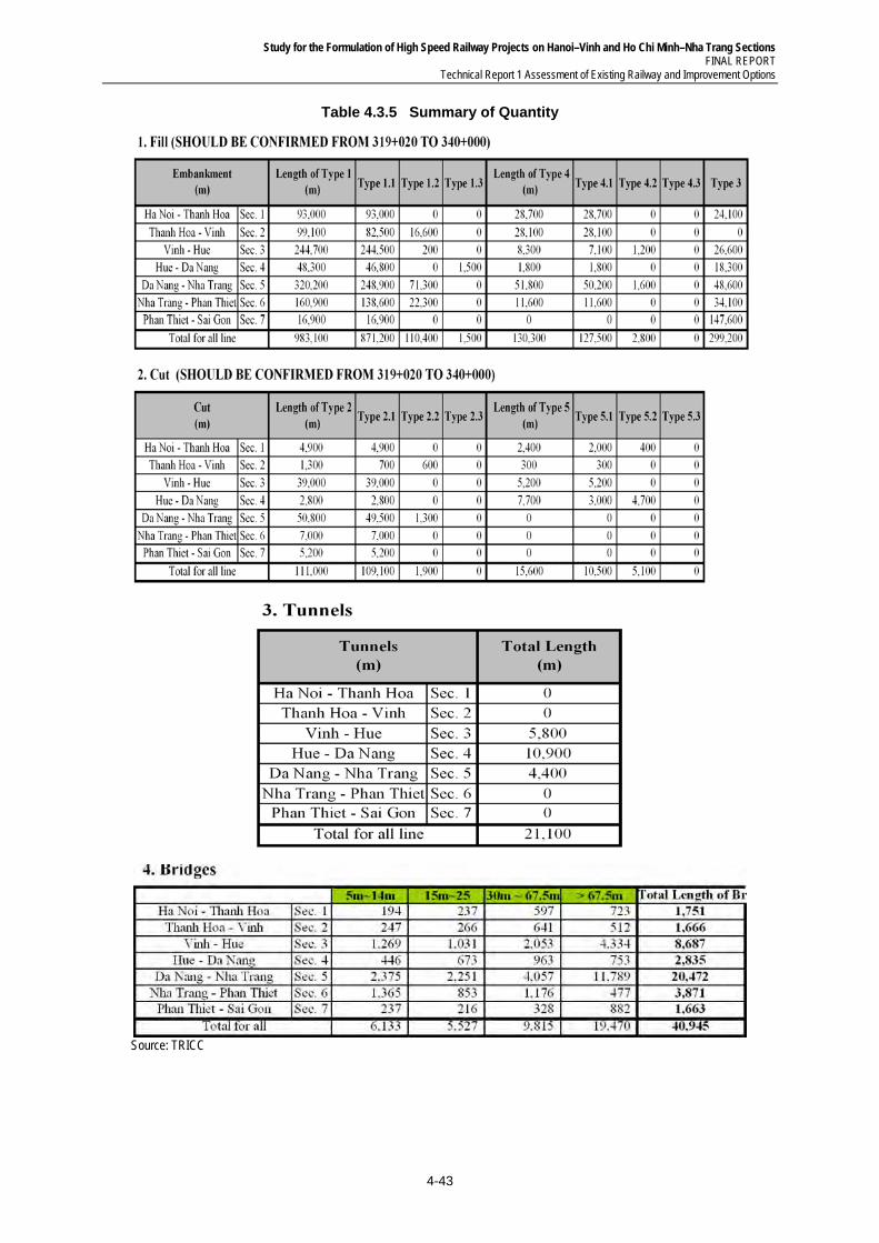
Study for the Formulation of High Speed Railway Projects on Hanoi–Vinh and Ho Chi Minh–Nha Trang Sections FINAL REPORT
Technical Report 1 Assessment of Existing Railway and Improvement Options
4-43
Table 4.3.5 Summary of Quantity
Source: TRICC
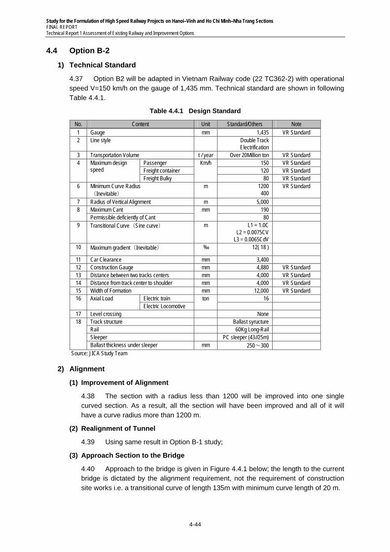
Study for the Formulation of High Speed Railway Projects on Hanoi–Vinh and Ho Chi Minh–Nha Trang Sections FINAL REPORT Technical Report 1 Assessment of Existing Railway and Improvement Options
4-44
4.4 Option B-2
1) Technical Standard
4.37 Option B2 will be adapted in Vietnam Railway code (22 TC362-2) with operational speed V=150 km/h on the gauge of 1,435 mm. Technical standard are shown in following Table 4.4.1.
Table 4.4.1 Design Standard
No. Content Unit Standard/Others Note 1 Gauge mm 1,435 VR Standard 2 Line style Double Track
Electrification
3 Transportation Volume t / year Over 20Million ton VR Standard 4 Maximum design
speed Passenger Km/h 150 VR Standard Freight container 120 VR Standard Freight Bulky 80 VR Standard
6 Minimum Curve Radius (Inevitable)
m 1200 400
VR Standard
7 Radius of Vertical Alignment m 5,000 8 Maximum Cant mm 190
Permissible deficiently of Cant 80 9 Transitional Curve(Sine curve) m L1 = 1.0C
L2 = 0.0075CV L3 = 0.0065CdV
10 Maximum gradient(Inevitable) ‰ 12( 18 )
11 Car Clearance mm 3,400 12 Construction Gauge mm 4,880 VR Standard 13 Distance between two tracks centers mm 4,000 VR Standard 14 Distance from track center to shoulder mm 4,000 VR Standard 15 Width of Formation mm 12,000 VR Standard 16 Axial Load Electric train ton 16
Electric Locomotive 17 Level crossing None 18 Track structure Ballast syructure
Rail 60Kg Long-Rail Sleeper PC sleeper (43//25m) Ballast thickness under sleeper mm 250~300
Source: JICA Study Team
2) Alignment
(1) Improvement of Alignment
4.38 The section with a radius less than 1200 will be improved into one single curved section. As a result, all the section will have been improved and all of it will have a curve radius more than 1200 m.
(2) Realignment of Tunnel
4.39 Using same result in Option B-1 study;
(3) Approach Section to the Bridge
4.40 Approach to the bridge is given in Figure 4.4.1 below; the length to the current bridge is dictated by the alignment requirement, not the requirement of construction site works i.e. a transitional curve of length 135m with minimum curve length of 20 m.
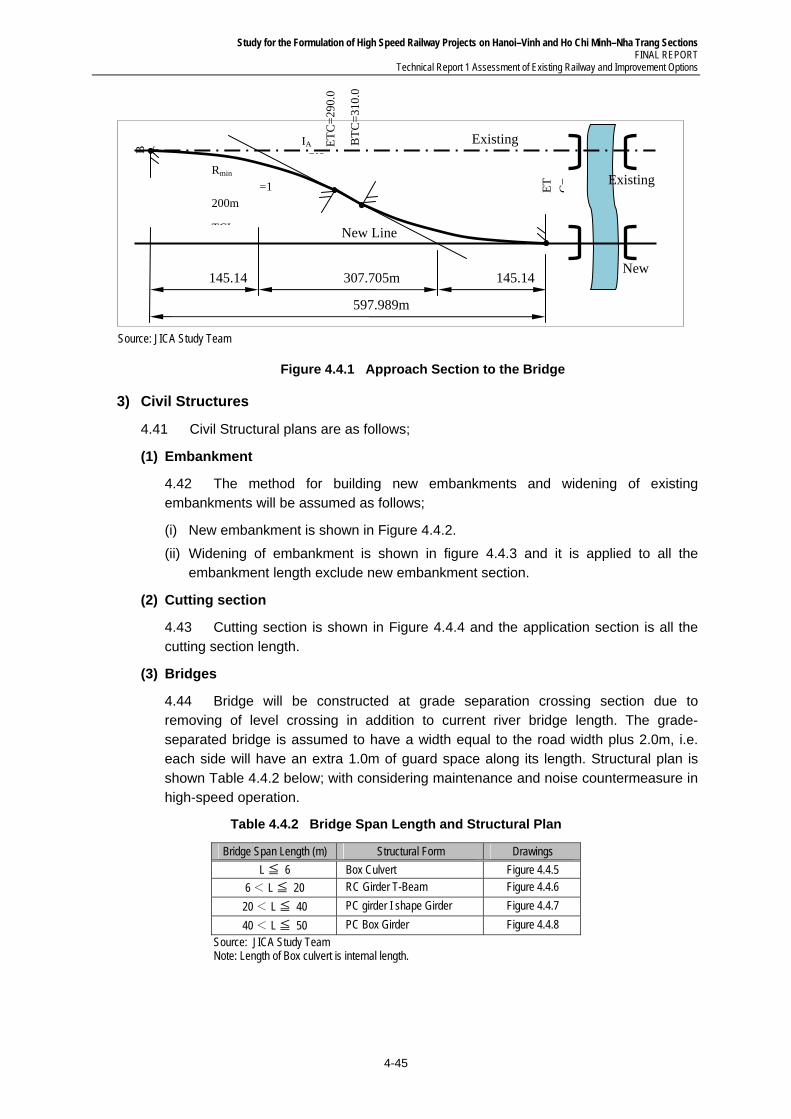
Study for the Formulation of High Speed Railway Projects on Hanoi–Vinh and Ho Chi Minh–Nha Trang Sections FINAL REPORT
Technical Report 1 Assessment of Existing Railway and Improvement Options
4-45
Source: JICA Study Team
Figure 4.4.1 Approach Section to the Bridge
3) Civil Structures
4.41 Civil Structural plans are as follows;
(1) Embankment
4.42 The method for building new embankments and widening of existing embankments will be assumed as follows;
(i) New embankment is shown in Figure 4.4.2.
(ii) Widening of embankment is shown in figure 4.4.3 and it is applied to all the embankment length exclude new embankment section.
(2) Cutting section
4.43 Cutting section is shown in Figure 4.4.4 and the application section is all the cutting section length.
(3) Bridges
4.44 Bridge will be constructed at grade separation crossing section due to removing of level crossing in addition to current river bridge length. The grade-separated bridge is assumed to have a width equal to the road width plus 2.0m, i.e. each side will have an extra 1.0m of guard space along its length. Structural plan is shown Table 4.4.2 below; with considering maintenance and noise countermeasure in high-speed operation.
Table 4.4.2 Bridge Span Length and Structural Plan
Bridge Span Length (m) Structural Form Drawings
≦L 6 Box Culvert Figure 4.4.5
6 < ≦L 20 RC Girder T-Beam Figure 4.4.6
20 < ≦L 40 PC girder I shape Girder Figure 4.4.7
40 < ≦L 50 PC Box Girder Figure 4.4.8
Source: JICA Study Team Note: Length of Box culvert is internal length.
597.989m
307.705m 145.14 145.14
Existing
Existing
New
B T
ET
C=
Rmin =1200m
TCL
IA 7°2
New Line
BT
C=
310.
0
ET
C=
290.
0
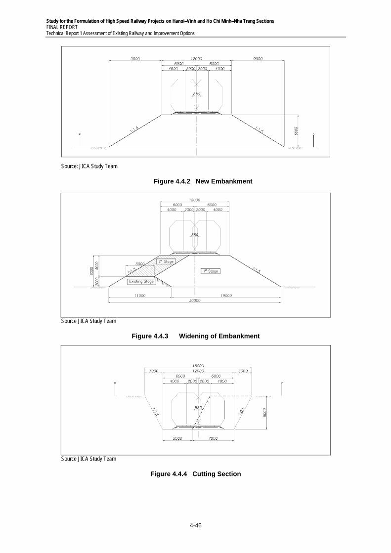
Study for the Formulation of High Speed Railway Projects on Hanoi–Vinh and Ho Chi Minh–Nha Trang Sections FINAL REPORT Technical Report 1 Assessment of Existing Railway and Improvement Options
4-46
Source: JICA Study Team
Figure 4.4.2 New Embankment
Source JICA Study Team
Figure 4.4.3 Widening of Embankment
Source JICA Study Team
Figure 4.4.4 Cutting Section
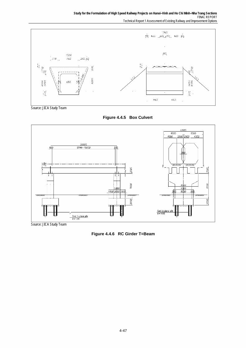
Study for the Formulation of High Speed Railway Projects on Hanoi–Vinh and Ho Chi Minh–Nha Trang Sections FINAL REPORT
Technical Report 1 Assessment of Existing Railway and Improvement Options
4-47
Source: JICA Study Team
Figure 4.4.5 Box Culvert
Source: JICA Study Team
Figure 4.4.6 RC Girder T=Beam
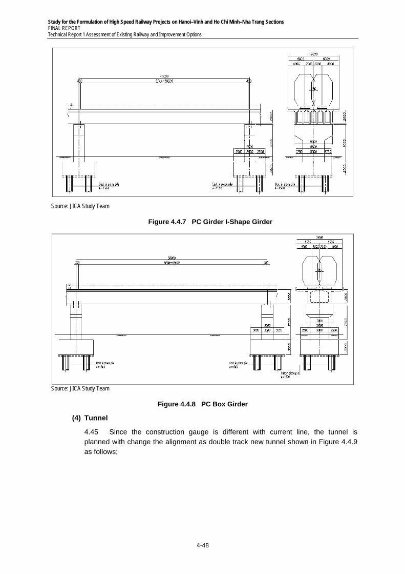
Study for the Formulation of High Speed Railway Projects on Hanoi–Vinh and Ho Chi Minh–Nha Trang Sections FINAL REPORT Technical Report 1 Assessment of Existing Railway and Improvement Options
4-48
Source: JICA Study Team
Figure 4.4.7 PC Girder I-Shape Girder
Source: JICA Study Team
Figure 4.4.8 PC Box Girder
(4) Tunnel
4.45 Since the construction gauge is different with current line, the tunnel is planned with change the alignment as double track new tunnel shown in Figure 4.4.9 as follows;
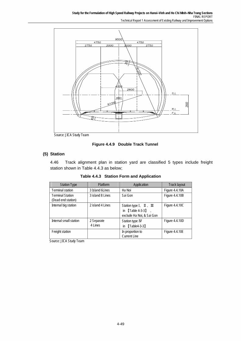
Study for the Formulation of High Speed Railway Projects on Hanoi–Vinh and Ho Chi Minh–Nha Trang Sections FINAL REPORT
Technical Report 1 Assessment of Existing Railway and Improvement Options
4-49
Source: JICA Study Team
Figure 4.4.9 Double Track Tunnel
(5) Station
4.46 Track alignment plan in station yard are classified 5 types include freight station shown in Table 4.4.3 as below;
Table 4.4.3 Station Form and Application
Station Type Platform Application Track layout
Terminal station 3 Island 6Lines Ha Noi Figure 4.4.10A Terminal Station (Dead end station)
3 island 8 Lines Sai Gon Figure 4.4.10B
Internal big station 2 island 4 Lines Station type I、Ⅱ、Ⅲ in 【Table 4-3-3】 。 exclude Ha Noi, & Sai Gon
Figure 4.4.10C
Internal small station 2 Separate 4 Lines
Station type Ⅳ in 【Table4-3-3】
Figure 4.4.10D
Freight station In proportion to Current Line
Figure 4.4.10E
Source: JICA Study Team
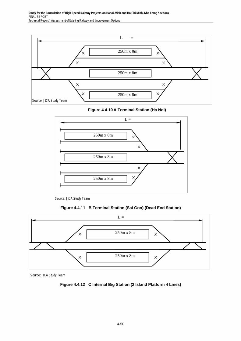
Study for the Formulation of High Speed Railway Projects on Hanoi–Vinh and Ho Chi Minh–Nha Trang Sections FINAL REPORT Technical Report 1 Assessment of Existing Railway and Improvement Options
4-50
Source: JICA Study Team
Figure 4.4.10 A Terminal Station (Ha Noi)
Source: JICA Study Team
Figure 4.4.11 B Terminal Station (Sai Gon) (Dead End Station)
Source: JICA Study Team
Figure 4.4.12 C Internal Big Station (2 Island Platform 4 Lines)
250m x 8m
250m x 8m
L =
250m x 8m
250m x 8m
250m x 8m
L =
250m x 8m
250m x 8m
L =
250m x 8m
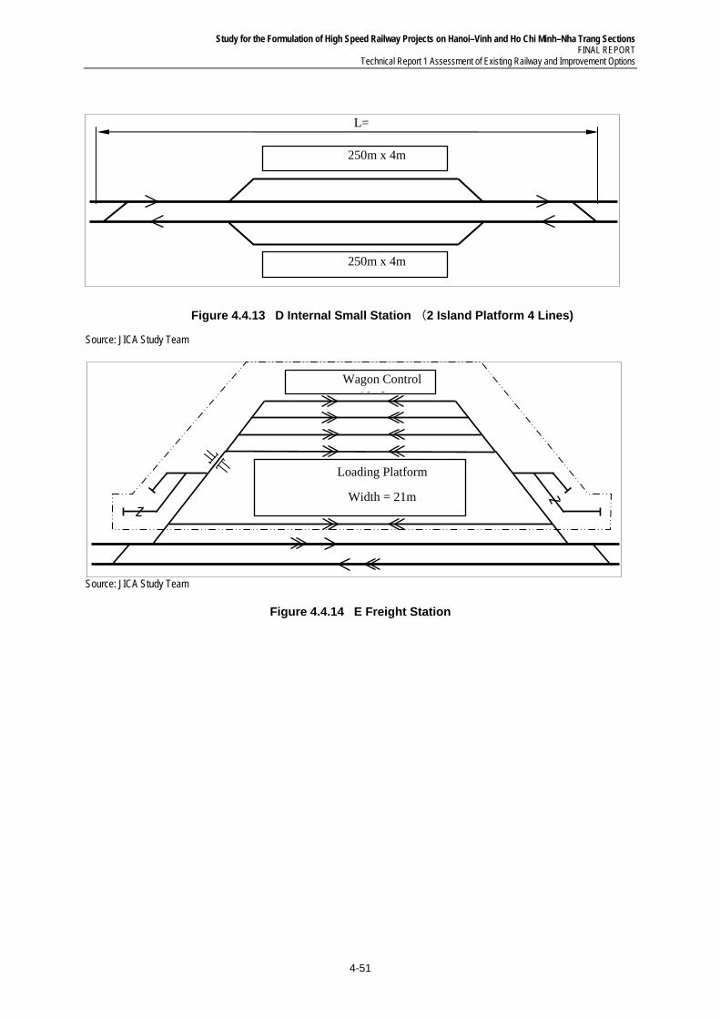
Study for the Formulation of High Speed Railway Projects on Hanoi–Vinh and Ho Chi Minh–Nha Trang Sections FINAL REPORT
Technical Report 1 Assessment of Existing Railway and Improvement Options
4-51
Figure 4.4.13 D Internal Small Station (2 Island Platform 4 Lines)
Source: JICA Study Team
Source: JICA Study Team
Figure 4.4.14 E Freight Station
Loading Platform
Width = 21m
Wagon Control Pl f
250m x 4m
250m x 4m
L=
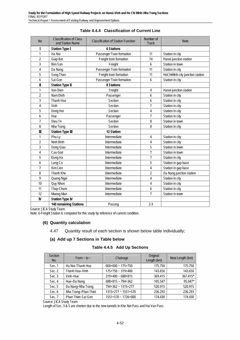
Study for the Formulation of High Speed Railway Projects on Hanoi–Vinh and Ho Chi Minh–Nha Trang Sections FINAL REPORT Technical Report 1 Assessment of Existing Railway and Improvement Options
4-52
Table 4.4.4 Classification of Current Line
No Classification of Class
and Station Name Classification of Station Function
Number of Track
Note
I Station Type I 6 Stations 1 Ha Noi Passenger Train formation 11 Station in city 2 Giap Bat Freight train formation 14 Hanoi junction station 3 Bim Son Freight 6 Station in town 4 Da Nang Passenger Train formation 11 Station in city 5 Song Than Freight train formation 11 HoChiMinh city junction station 6 Sai Gon Passenger Train formation 6 Station in city II Station Type II 8 Stations 1 Van Dien Freight 4 Hanoi junction station 2 Nam Đinh Passenger 6 Station in city 3 Thanh Hoa Section 6 Station in city 4 Vinh Section 7 Station in city 5 Dong Hoi Section 4 Station in city 6 Hue Passenger 7 Station in city 7 Dieu Tri Section 8 Station in town 8 Nha Trang Section 8 Station in city III Station Type III 12 Station 1 Phu Ly Intermediate 4 Station in city 2 Ninh Binh Intermediate 4 Station in city 3 Dong Giao Intermediate 5 Station in town 4 Cau Giat Intermediate 7 Station in town 5 Đong Ha Intermediate 7 Station in city 6 Lang Co Intermediate 5 Station in gap base 7 Kim Lien Intermediate 4 Station in gap base 8 Thanh Khe Intermediate 2 Da Nang junction station 9 Quang Ngai Intermediate 4 Station in city 10 Quy Nhon Intermediate 4 Station in city 11 Thap Cham Intermediate 6 Station in city 12 Muong Man Intermediate 7 Station in town IV Station Type IV 140 remaining Stations Passing 2-3
Source: JICA Study Team Note: 6-Freight Station is computed for this study by reference of current condition.
(6) Quantity calculation
4.47 Quantity result of each section is shown below table individually;
(a) Add up 7 Sections in Table below
Table 4.4.5 Add Up Sections
Section No.
From ~ to ~ Chainage Original
Length (km) New Length (km)
Sec. 1 Ha Noi–Thanh Hoa 000+000 ~ 175+750 175.750 175.750 Sec. 2 Thanh Hoa–Vinh 175+750 ~ 319+400 143.650 143.650 Sec. 3 Vinh–Hue 319+400 ~ 688+815 369.415 367.415* Sec. 4 Hue–Da Nang 688+815 ~ 794+362 105.547 95.047* Sec. 5 Da Nang–Nha Trang 794+362 ~ 1315+277 520.915 520.915 Sec. 6 Nha Trang–Phan Thiet 1315+277 ~ 1551+570 236.293 236.293 Sec. 7 Phan Thiet–Sai Gon 1551+570 ~ 1726+000 174.430 174.430
Source: JICA Study Team Length of Sec. 3 & 5 are shorten due to the new tunnels in Khe Net Pass and Hai Van Pass
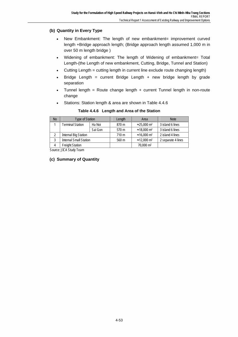
Study for the Formulation of High Speed Railway Projects on Hanoi–Vinh and Ho Chi Minh–Nha Trang Sections FINAL REPORT
Technical Report 1 Assessment of Existing Railway and Improvement Options
4-53
(b) Quantity in Every Type
New Embankment: The length of new embankment= improvement curved length +Bridge approach length; (Bridge approach length assumed 1,000 m in over 50 m length bridge )
Widening of embankment: The length of Widening of embankment= Total Length-(the Length of new embankment, Cutting, Bridge, Tunnel and Station)
Cutting Length = cutting length in current line exclude route changing length)
Bridge Length = current Bridge Length + new bridge length by grade separation
Tunnel length = Route change length + current Tunnel length in non-route change
Stations: Station length & area are shown in Table 4.4.6
Table 4.4.6 Length and Area of the Station
No Type of Station Length Area Note
1 Terminal Station Ha Noi 870 m ≈25,000 m2 3 island 6 lines Sai Gon 570 m ≈18,000 m2 3 island 6 lines
2 Internal Big Station 710 m ≈16,000 m2 2 island 4 lines 3 Internal Small Station 560 m ≈12,000 m2 2 separate 4 lines 4 Freight Station 70,000 m2
Source: JICA Study Team
(c) Summary of Quantity
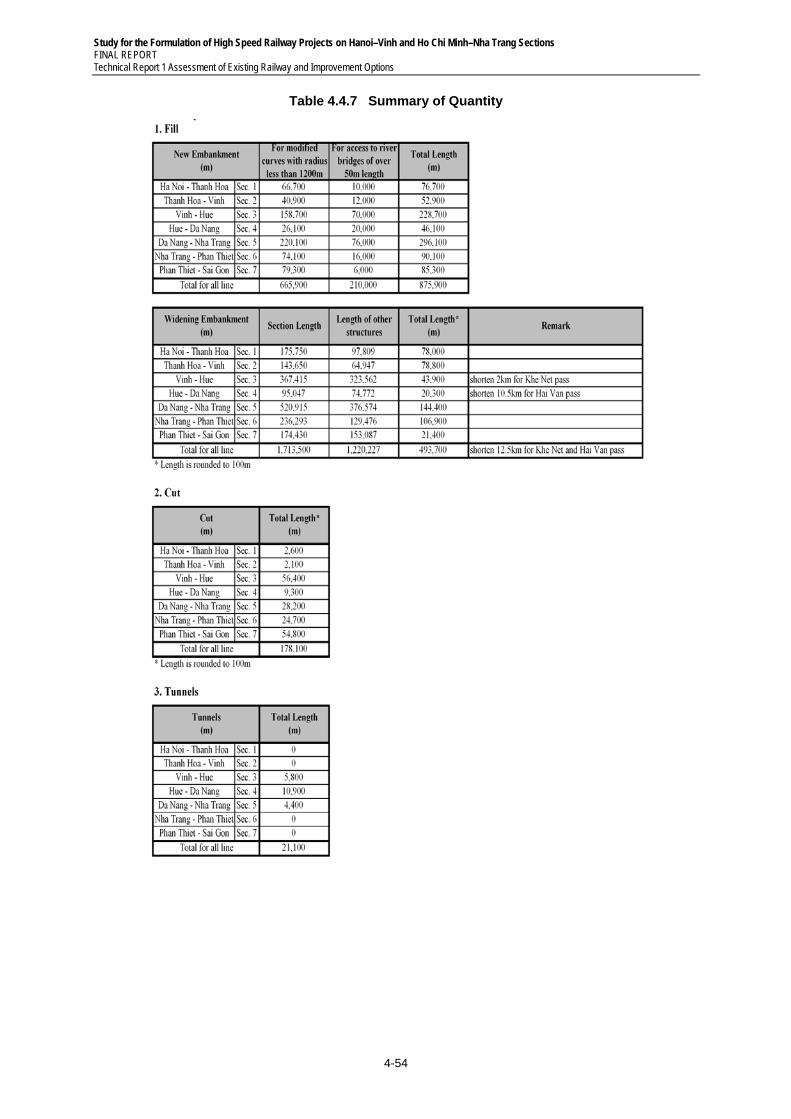
Study for the Formulation of High Speed Railway Projects on Hanoi–Vinh and Ho Chi Minh–Nha Trang Sections FINAL REPORT Technical Report 1 Assessment of Existing Railway and Improvement Options
4-54
Table 4.4.7 Summary of Quantity
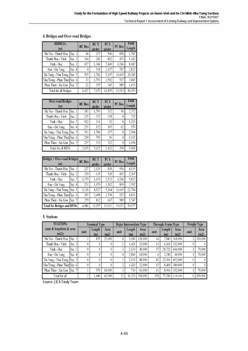
Study for the Formulation of High Speed Railway Projects on Hanoi–Vinh and Ho Chi Minh–Nha Trang Sections FINAL REPORT
Technical Report 1 Assessment of Existing Railway and Improvement Options
4-55
Source: JICA Study Team
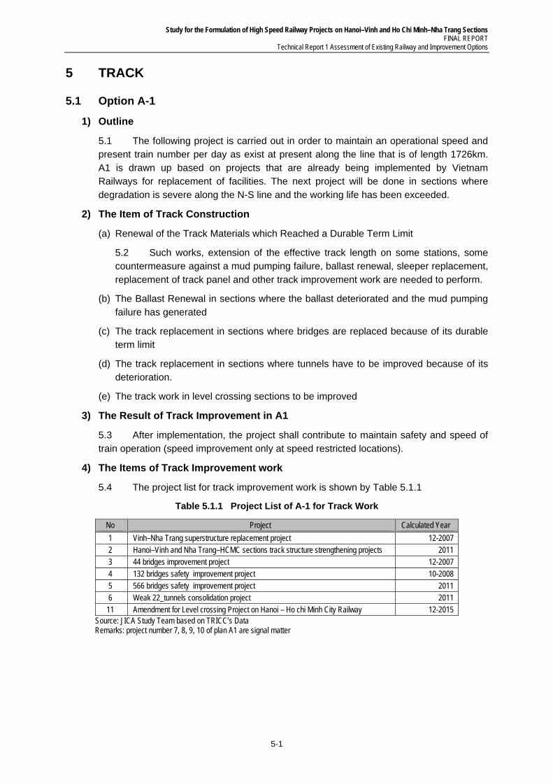
Study for the Formulation of High Speed Railway Projects on Hanoi–Vinh and Ho Chi Minh–Nha Trang Sections FINAL REPORT
Technical Report 1 Assessment of Existing Railway and Improvement Options
5-1
5 TRACK
5.1 Option A-1
1) Outline
5.1 The following project is carried out in order to maintain an operational speed and present train number per day as exist at present along the line that is of length 1726km. A1 is drawn up based on projects that are already being implemented by Vietnam Railways for replacement of facilities. The next project will be done in sections where degradation is severe along the N-S line and the working life has been exceeded.
2) The Item of Track Construction
(a) Renewal of the Track Materials which Reached a Durable Term Limit
5.2 Such works, extension of the effective track length on some stations, some countermeasure against a mud pumping failure, ballast renewal, sleeper replacement, replacement of track panel and other track improvement work are needed to perform.
(b) The Ballast Renewal in sections where the ballast deteriorated and the mud pumping failure has generated
(c) The track replacement in sections where bridges are replaced because of its durable term limit
(d) The track replacement in sections where tunnels have to be improved because of its deterioration.
(e) The track work in level crossing sections to be improved
3) The Result of Track Improvement in A1
5.3 After implementation, the project shall contribute to maintain safety and speed of train operation (speed improvement only at speed restricted locations).
4) The Items of Track Improvement work
5.4 The project list for track improvement work is shown by Table 5.1.1
Table 5.1.1 Project List of A-1 for Track Work
No Project Calculated Year
1 Vinh–Nha Trang superstructure replacement project 12-2007 2 Hanoi–Vinh and Nha Trang–HCMC sections track structure strengthening projects 2011 3 44 bridges improvement project 12-2007 4 132 bridges safety improvement project 10-2008 5 566 bridges safety improvement project 2011 6 Weak 22_tunnels consolidation project 2011
11 Amendment for Level crossing Project on Hanoi – Ho chi Minh City Railway 12-2015 Source: JICA Study Team based on TRICC’s Data Remarks: project number 7, 8, 9, 10 of plan A1 are signal matter
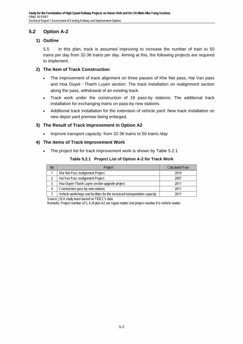
Study for the Formulation of High Speed Railway Projects on Hanoi–Vinh and Ho Chi Minh–Nha Trang Sections FINAL REPORT Technical Report 1 Assessment of Existing Railway and Improvement Options
5-2
5.2 Option A-2
1) Outline
5.5 In this plan, track is assumed improving to increase the number of train to 50 trains per day from 32-36 trains per day. Aiming at this, the following projects are required to implement.
2) The Item of Track Construction
The improvement of track alignment on three passes of Khe Net pass, Hai Van pass
and Hoa Duyet-Thanh Luyen section: The track installation on realignment section
along the pass, withdrawal of an existing track.
Track work under the construction of 18 pass-by stations: The additional track installation for exchanging trains on pass-by new stations.
Additional track installation for the extension of vehicle yard: New track installation on new depot yard premise being enlarged.
3) The Result of Track Improvement in Option A2
Improve transport capacity: from 32-36 trains to 50 trains /day
4) The items of Track Improvement Work
The project list for track improvement work is shown by Table 5.2.1
Table 5.2.1 Project List of Option A-2 for Track Work
No Project Calculated Year
1 Khe Net Pass realignment Project 2010 2 Hai Van Pass realignment Project 2007 3 Hoa Duyet–Thanh Luyen section upgrade project 2011 4 Construction pass-by new stations 2011 7 Vehicle workshops and facilities for the increased transportation capacity 2011
Source: JICA study team based on TRICC’s data Remarks: Project number of 5, 6 of plan A2 are signal matter and project number 8 is vehicle matter.
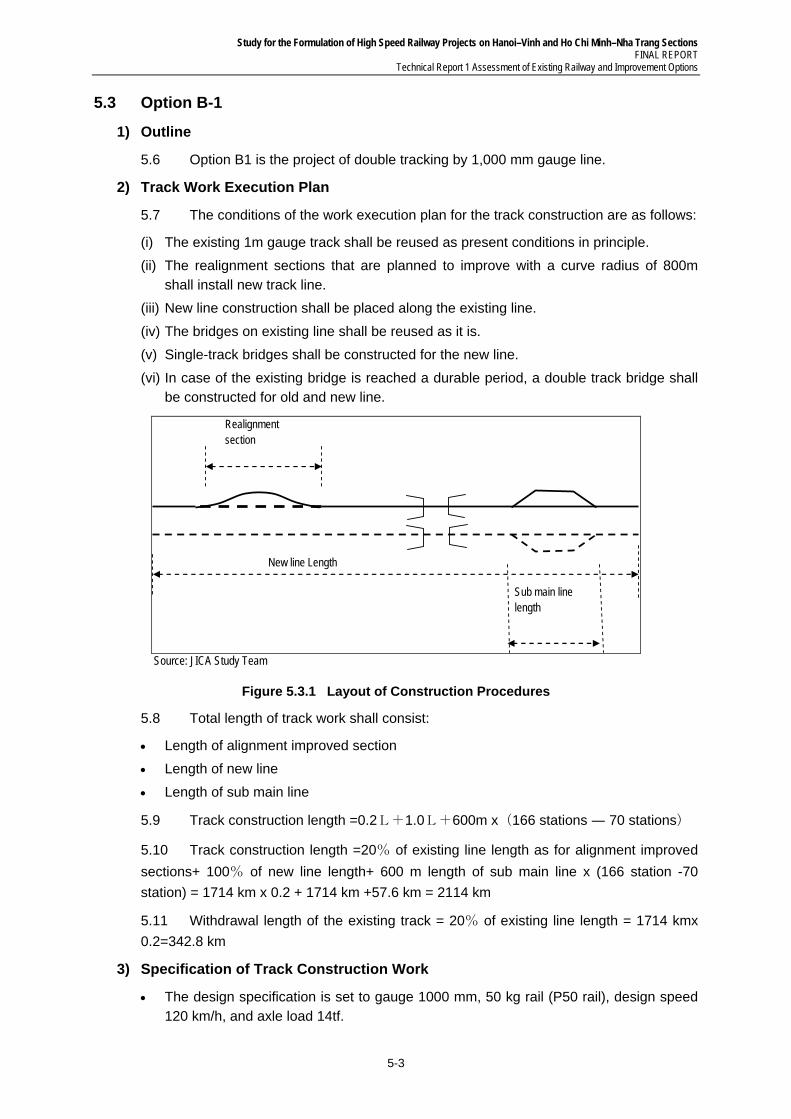
Study for the Formulation of High Speed Railway Projects on Hanoi–Vinh and Ho Chi Minh–Nha Trang Sections FINAL REPORT
Technical Report 1 Assessment of Existing Railway and Improvement Options
5-3
5.3 Option B-1
1) Outline
5.6 Option B1 is the project of double tracking by 1,000 mm gauge line.
2) Track Work Execution Plan
5.7 The conditions of the work execution plan for the track construction are as follows:
(i) The existing 1m gauge track shall be reused as present conditions in principle.
(ii) The realignment sections that are planned to improve with a curve radius of 800m shall install new track line.
(iii) New line construction shall be placed along the existing line.
(iv) The bridges on existing line shall be reused as it is.
(v) Single-track bridges shall be constructed for the new line.
(vi) In case of the existing bridge is reached a durable period, a double track bridge shall be constructed for old and new line.
Realignment section
New line Length
Sub main line length
Source: JICA Study Team
Figure 5.3.1 Layout of Construction Procedures
5.8 Total length of track work shall consist:
Length of alignment improved section
Length of new line
Length of sub main line
5.9 Track construction length =0.2L+1.0L+600m x(166 stations ― 70 stations)
5.10 Track construction length =20% of existing line length as for alignment improved
sections+ 100% of new line length+ 600 m length of sub main line x (166 station -70
station) = 1714 km x 0.2 + 1714 km +57.6 km = 2114 km
5.11 Withdrawal length of the existing track = 20% of existing line length = 1714 kmx
0.2=342.8 km
3) Specification of Track Construction Work
The design specification is set to gauge 1000 mm, 50 kg rail (P50 rail), design speed 120 km/h, and axle load 14tf.

Study for the Formulation of High Speed Railway Projects on Hanoi–Vinh and Ho Chi Minh–Nha Trang Sections FINAL REPORT Technical Report 1 Assessment of Existing Railway and Improvement Options
5-4
The track structure design is with Pre-stressed Concrete sleeper, 38 sleepers per 25m length track, and 250 mm of ballast thicknesses.
The Continuous Welded Rail is applied between stations with a curve radius of 500m or more.
The track in station area is installed with a jointed rail.
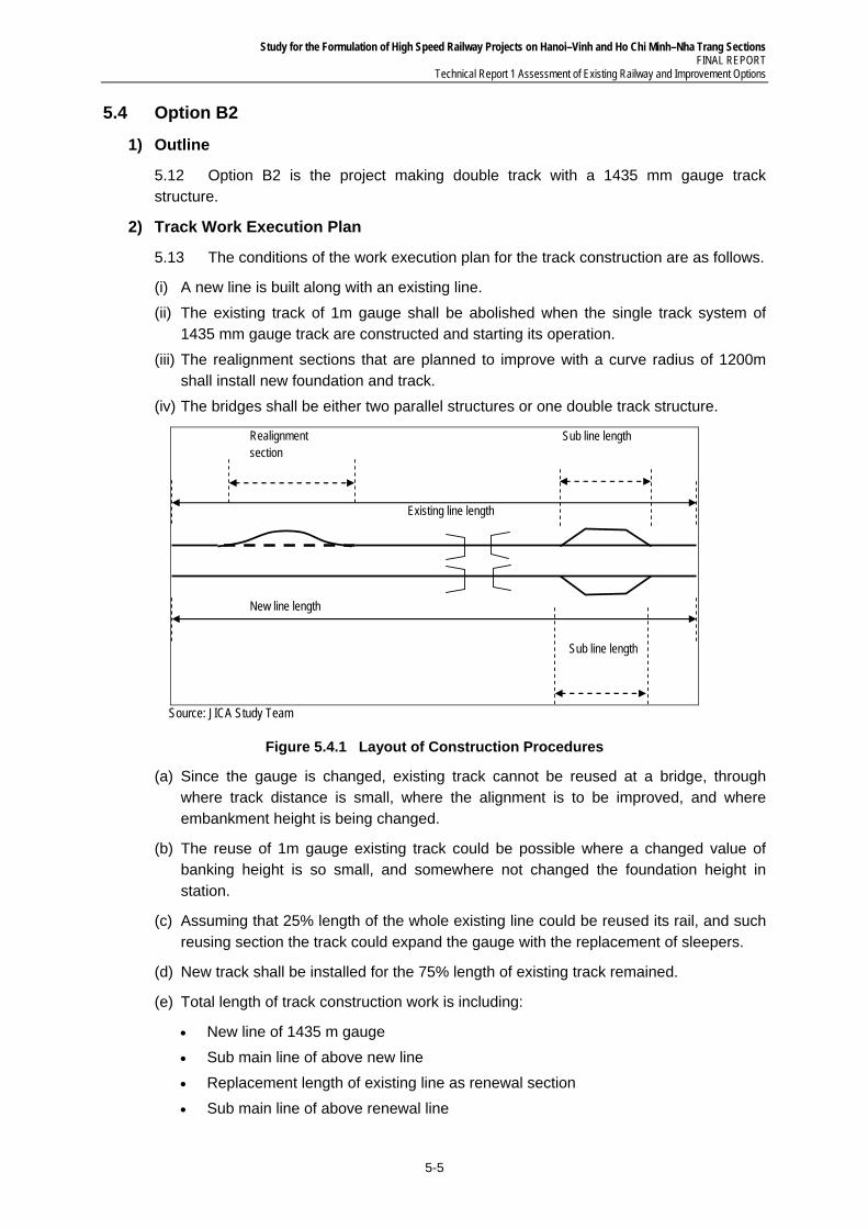
Study for the Formulation of High Speed Railway Projects on Hanoi–Vinh and Ho Chi Minh–Nha Trang Sections FINAL REPORT
Technical Report 1 Assessment of Existing Railway and Improvement Options
5-5
5.4 Option B2
1) Outline
5.12 Option B2 is the project making double track with a 1435 mm gauge track structure.
2) Track Work Execution Plan
5.13 The conditions of the work execution plan for the track construction are as follows.
(i) A new line is built along with an existing line.
(ii) The existing track of 1m gauge shall be abolished when the single track system of 1435 mm gauge track are constructed and starting its operation.
(iii) The realignment sections that are planned to improve with a curve radius of 1200m shall install new foundation and track.
(iv) The bridges shall be either two parallel structures or one double track structure.
Realignment section
New line length
Existing line length
Sub line length
Sub line length
Source: JICA Study Team
Figure 5.4.1 Layout of Construction Procedures
(a) Since the gauge is changed, existing track cannot be reused at a bridge, through where track distance is small, where the alignment is to be improved, and where embankment height is being changed.
(b) The reuse of 1m gauge existing track could be possible where a changed value of banking height is so small, and somewhere not changed the foundation height in station.
(c) Assuming that 25% length of the whole existing line could be reused its rail, and such reusing section the track could expand the gauge with the replacement of sleepers.
(d) New track shall be installed for the 75% length of existing track remained.
(e) Total length of track construction work is including:
New line of 1435 m gauge
Sub main line of above new line
Replacement length of existing line as renewal section
Sub main line of above renewal line
Study for the Formulation of High Speed Railway Projects on Hanoi–Vinh and Ho Chi Minh–Nha Trang Sections FINAL REPORT Technical Report 1 Assessment of Existing Railway and Improvement Options
5-6
Gauge widening sections of existing line being reused
(f) Length of sub main line assumes about 5% of the whole line.
(g) Length of new track installation = 1714 km x {(1.0+0.05) + (0.75+0.05)} =3171 km
(h) Section to be expand the track gauge =1714 km x0.25=428.5 km
(i) Withdrawal length of the track =1714 km x (0.75+0.05) =1371 km
3) Specification of Track Construction Work
The design specification is set to gauge 1435 mm, 60 kg rails (P60 rail), design speed 150 km/h, and axle-load 17tf.
Track structure design is with pre stressed concrete sleeper, 41 sleepers per 25 m length, and 250 mm of ballast thicknesses.
The Continuous Welded Rail is applied to main line where the curve radius of 500 m or more in principle.
The sub main line on station part is applied a track structure with jointed rail.
Study for the Formulation of High Speed Railway Projects on Hanoi–Vinh and Ho Chi Minh–Nha Trang Sections FINAL REPORT
Technical Report 1 Assessment of Existing Railway and Improvement Options
6-1
6 POWER SUPPLY SYSTEM
6.1 General
6.1 As the double-tracking/electrification project, the Study team will propose an innovated system to have blended the most reliable and advanced technologies and equipment/facilities that are widely in use and fully proven in Japan. For the maintenance of the system after introduction, JICA Study Team will also adopt a thoroughly deliberated system in principle.
1) Power Receiving System
6.2 Railway substations will be connected through a normal service circuit and a spare circuit via T-branches separately with different transmission routes of the extra-high tension transmission network of Vietnam Electricity (EVN). The location of T-branches and the voltage of power are subject to the negotiation with EVN. The receiving voltage shall preferably be that of the 220 KV transmission network.
2) Feeding Circuit
(1) Composition of Feeding Circuit
6.3 A sectioning post will be set at the center between the adjacent substations A and B in AC-electrified sections. Power is normally supplied from these substations A and B up to the sectioning post.
6.4 In case either one of the substations has failed, feeding is extended, in that power is supplied from the substation remaining intact to the failed substation over-passing the sectioning post in between. To limit the length of power shutdown section at accidents or during maintenance work, an auxiliary sectioning post will be set between a substation and its adjacent sectioning post.
(2) Power Supply to Feeding Circuits
(a) Power Supply through AC Auto Transformers
6.5 JICA Study Team will propose adoption of autotransformer (AT feeding) system, the standard version for AC electrification in Japan, among various feeding systems used in AC electrified railways.
(b) Direction-side Different- Phase Feeding System
6.6 Single-phase AC electrification railways receive three-phase AC current from electric power companies and convert it into two single-phase AC currents having 90-degree different phases and supply them separately to the feeding circuits on the different sides of the substation, as adopted for the narrow-gauge and Shinkansen railways in Japan. JICA Study Team will recommend for Vietnam to adopt this system, which is called the different- side different- phase feeding system (power of different phases is supplied to different sides, with both up- and down-trains on the same side supplied with power of the same phase).
3) Contact Wire Voltage
6.7 The standard contact wire voltage is 25.5 KV, with fluctuation ranges of effective value a specified below.
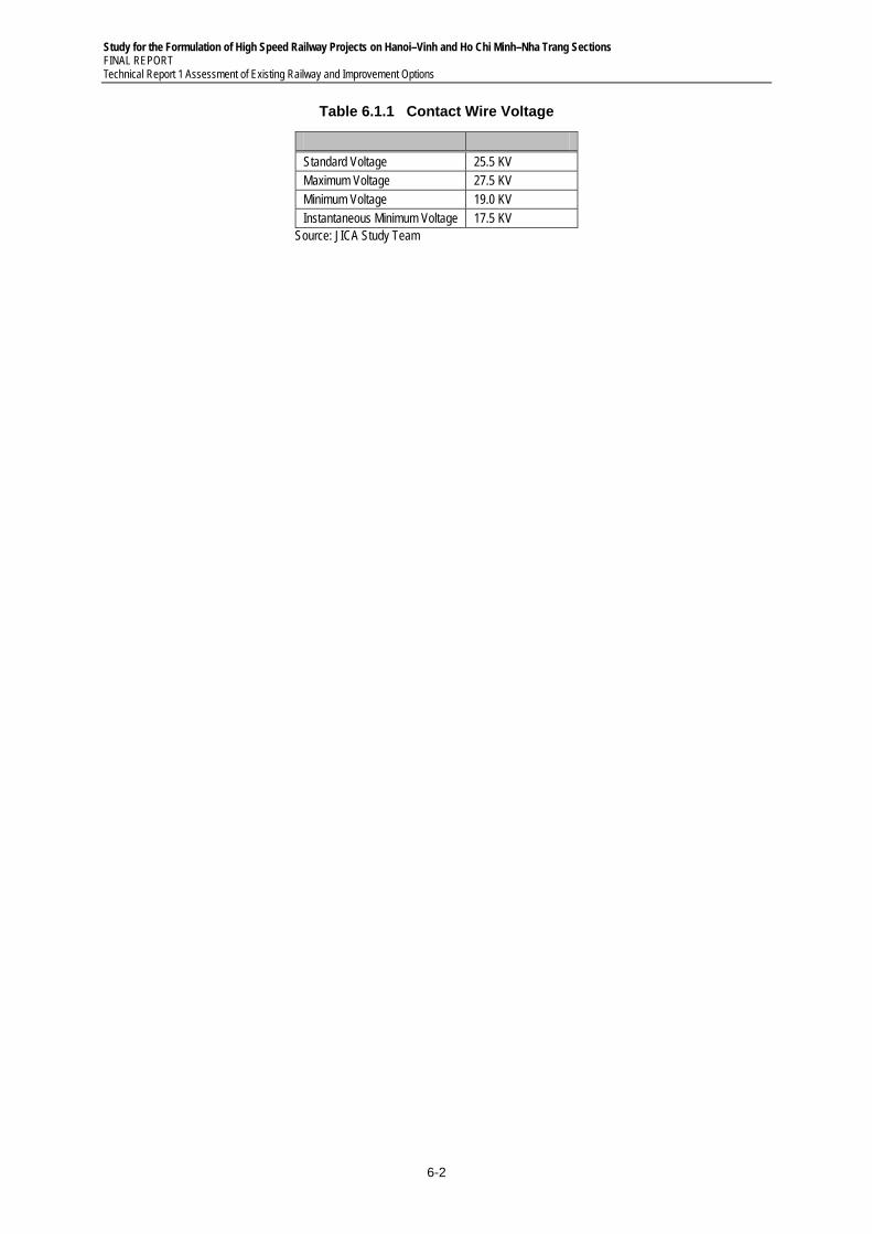
Study for the Formulation of High Speed Railway Projects on Hanoi–Vinh and Ho Chi Minh–Nha Trang Sections FINAL REPORT Technical Report 1 Assessment of Existing Railway and Improvement Options
6-2
Table 6.1.1 Contact Wire Voltage
Standard Voltage 25.5 KV Maximum Voltage 27.5 KV Minimum Voltage 19.0 KV Instantaneous Minimum Voltage 17.5 KV
Source: JICA Study Team
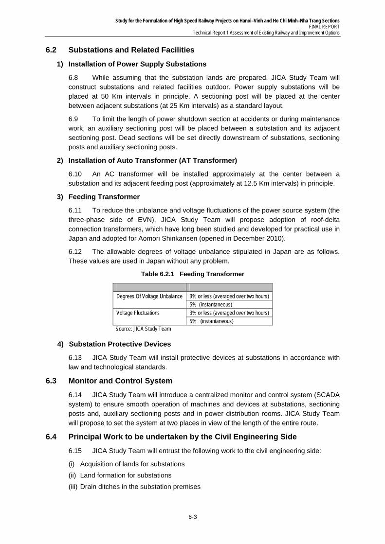
Study for the Formulation of High Speed Railway Projects on Hanoi–Vinh and Ho Chi Minh–Nha Trang Sections FINAL REPORT
Technical Report 1 Assessment of Existing Railway and Improvement Options
6-3
6.2 Substations and Related Facilities
1) Installation of Power Supply Substations
6.8 While assuming that the substation lands are prepared, JICA Study Team will construct substations and related facilities outdoor. Power supply substations will be placed at 50 Km intervals in principle. A sectioning post will be placed at the center between adjacent substations (at 25 Km intervals) as a standard layout.
6.9 To limit the length of power shutdown section at accidents or during maintenance work, an auxiliary sectioning post will be placed between a substation and its adjacent sectioning post. Dead sections will be set directly downstream of substations, sectioning posts and auxiliary sectioning posts.
2) Installation of Auto Transformer (AT Transformer)
6.10 An AC transformer will be installed approximately at the center between a substation and its adjacent feeding post (approximately at 12.5 Km intervals) in principle.
3) Feeding Transformer
6.11 To reduce the unbalance and voltage fluctuations of the power source system (the three-phase side of EVN), JICA Study Team will propose adoption of roof-delta connection transformers, which have long been studied and developed for practical use in Japan and adopted for Aomori Shinkansen (opened in December 2010).
6.12 The allowable degrees of voltage unbalance stipulated in Japan are as follows. These values are used in Japan without any problem.
Table 6.2.1 Feeding Transformer
Degrees Of Voltage Unbalance 3% or less (averaged over two hours) 5% (instantaneous)
Voltage Fluctuations 3% or less (averaged over two hours) 5% (instantaneous)
Source: JICA Study Team
4) Substation Protective Devices
6.13 JICA Study Team will install protective devices at substations in accordance with law and technological standards.
6.3 Monitor and Control System
6.14 JICA Study Team will introduce a centralized monitor and control system (SCADA system) to ensure smooth operation of machines and devices at substations, sectioning posts and, auxiliary sectioning posts and in power distribution rooms. JICA Study Team will propose to set the system at two places in view of the length of the entire route.
6.4 Principal Work to be undertaken by the Civil Engineering Side
6.15 JICA Study Team will entrust the following work to the civil engineering side:
(i) Acquisition of lands for substations
(ii) Land formation for substations
(iii) Drain ditches in the substation premises
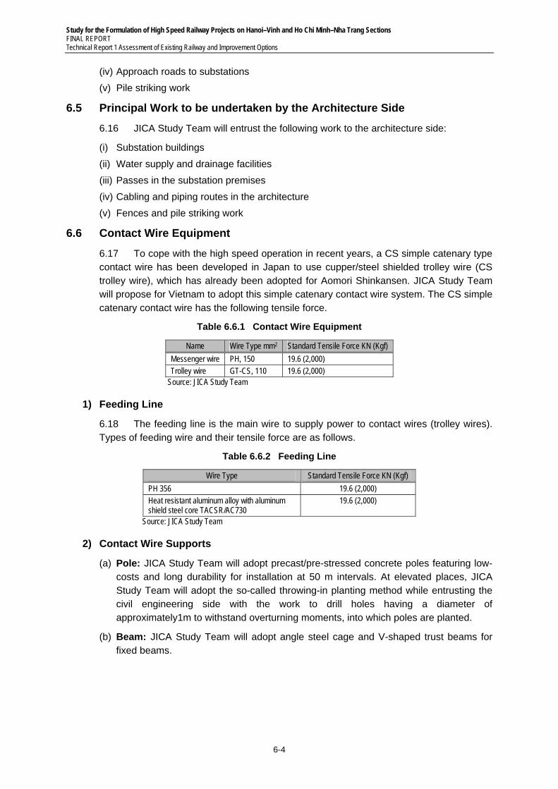
Study for the Formulation of High Speed Railway Projects on Hanoi–Vinh and Ho Chi Minh–Nha Trang Sections FINAL REPORT Technical Report 1 Assessment of Existing Railway and Improvement Options
6-4
(iv) Approach roads to substations
(v) Pile striking work
6.5 Principal Work to be undertaken by the Architecture Side
6.16 JICA Study Team will entrust the following work to the architecture side:
(i) Substation buildings
(ii) Water supply and drainage facilities
(iii) Passes in the substation premises
(iv) Cabling and piping routes in the architecture
(v) Fences and pile striking work
6.6 Contact Wire Equipment
6.17 To cope with the high speed operation in recent years, a CS simple catenary type contact wire has been developed in Japan to use cupper/steel shielded trolley wire (CS trolley wire), which has already been adopted for Aomori Shinkansen. JICA Study Team will propose for Vietnam to adopt this simple catenary contact wire system. The CS simple catenary contact wire has the following tensile force.
Table 6.6.1 Contact Wire Equipment
Name Wire Type mm2 Standard Tensile Force KN (Kgf)
Messenger wire PH, 150 19.6 (2,000) Trolley wire GT-CS, 110 19.6 (2,000)
Source: JICA Study Team
1) Feeding Line
6.18 The feeding line is the main wire to supply power to contact wires (trolley wires). Types of feeding wire and their tensile force are as follows.
Table 6.6.2 Feeding Line
Wire Type Standard Tensile Force KN (Kgf)
PH 356 19.6 (2,000) Heat resistant aluminum alloy with aluminum shield steel core TACSR/AC730
19.6 (2,000)
Source: JICA Study Team
2) Contact Wire Supports
(a) Pole: JICA Study Team will adopt precast/pre-stressed concrete poles featuring low-costs and long durability for installation at 50 m intervals. At elevated places, JICA Study Team will adopt the so-called throwing-in planting method while entrusting the civil engineering side with the work to drill holes having a diameter of approximately1m to withstand overturning moments, into which poles are planted.
(b) Beam: JICA Study Team will adopt angle steel cage and V-shaped trust beams for fixed beams.
Study for the Formulation of High Speed Railway Projects on Hanoi–Vinh and Ho Chi Minh–Nha Trang Sections FINAL REPORT
Technical Report 1 Assessment of Existing Railway and Improvement Options
6-5
(c) Movable Bracket: JICA Study Team will use movable brackets to support contact wires.
(d) Supports in Tunnel: JICA Study Team will adopt steel pipe piers fixed at the ceiling in principle as the support in tunnel.
(e) Insulator: JICA Study Team will use suspension insulators; stem insulators and other insulators to support feeding wires, contact wires and other wires, steady braces and pull-off arms and other auxiliaries at poles, beams and arms or to electrically separate feeding wires from contact fires.
3) Contact Wire Facilities Monolithic With Civil Structures
6.19 The contact wire facilities to be constructed as monolithic with civil structures are as follows:
Pole foundation, support foundation, structures in tunnel (ceiling piers, branches, machine/material shafts, maintenance paths), grounding
Structures to cross pipes and the like are subject to negotiation with the civil engineering side at the design stage.
Study for the Formulation of High Speed Railway Projects on Hanoi–Vinh and Ho Chi Minh–Nha Trang Sections FINAL REPORT Technical Report 1 Assessment of Existing Railway and Improvement Options
6-6
6.7 Facilities for Lighting and Power
6.20 The facilities of lighting and power will be designed as those for power to be supplied to loads other than the power required to run electric cars. Major loads are lighting at stations and rolling stock bases and power to operate machines. The facilities of power to be supplied to such loads will be composed of systems normally used by electric railways and bulk users. Power will be supplied for train operation and marketing windows through duplicated circuits in principle.
6.21 As the reliability of power reception seems to differ from area to area, emergency power generators will be installed to ensure the reliability of power source.
1) Contents of System
(1) Power Distributing Stations
6.22 Power distributing stations will be constructed at stations and rolling stock bases to receive high-voltage power from the transmission network of EVN or the Vietnamese electric power company. Power will be transmitted to the loads at stations through cables after the voltage is dropped at power distributing stations. The status of machines and equipment will remotely be monitored and controlled through a system incorporated in the SCADA system.
(2) Power Distributing Lines
High-voltage power distributing lines (three-phase 6.5 KV power cables) will be laid to supply power to the facilities existing between stations.
Power cables will be laid in the cable ducts installed by the civil engineering side in open sections and attached to the walls in tunnel.
Power will be supplied to maintenance bases, signal and telecommunication machine rooms and substations existing between stations through high-voltage cables branched from the power transmission network.
Study for the Formulation of High Speed Railway Projects on Hanoi–Vinh and Ho Chi Minh–Nha Trang Sections FINAL REPORT
Technical Report 1 Assessment of Existing Railway and Improvement Options
7-1
7 SIGNALING AND TELECOMMUNICATION
7.1 Option A-1
1) General
7.1 Three projects on the signaling and telecommunication are on-going between Hanoi and Saigon (refer to (2)(a)-(c)). Level crossing projects on the North-South Railway line are proposed (refer to (2)(d)). They all aim to upgrade the safety or to replace the obsolete railway signaling and communication system currently used on Hanoi-Saigon sections. Two other projects on the signaling and telecommunication are completed from 2005 to now between Hanoi and Saigon. One of them is listed below for understanding the on-going projects (refer to (2)(e)) as well. The outlines and scopes of the projects are stated below.
2) Related Projects
(1) Modernization of the Signaling and Telecommunication System of the Hanoi-Vinh Railway (Phase II) Project (On-going Project)
7.2 The Objectives of this project are to replace the obsolete railway signaling and communication system currently used on Hanoi Vinh section with new signaling and telecommunication system which applies advanced and modern technologies
(a) Scope of Project: Hanoi–Vinh (319 km) and branch lines
(b) Scale of Investment
Signaling system
Electric interlocking equipment for 31 stations
Axle counter-based block equipment for 34 stations
Centralized Traffic Control system (CTC) on Hanoi-Vinh section
Telecommunication system
Using SDH devices of STM-1 transmission speed, upgradable to STM-4
Dedicated digital telephone system
Installing communication systems for stations on branch lines so that these systems can be uniform with those of stations on main lines
(c) Implementation Schedule: 2007–2010
(2) Modernization of the Signaling and Telecommunication System of Vinh–Sai Gon Railway (Phase I) (On-going Project)
7.3 The objectives of this project are to reject the backward and weakness of the existing signaling and telecommunication system
(a) Scope of Project: The North-south railway line (319km-1,726km section)
(b) Scale of Investment:
Signaling System
− Relay interlocking equipment in combination with axle counter for 316 turnouts of stations on Da Nang–Sai Gon
Study for the Formulation of High Speed Railway Projects on Hanoi–Vinh and Ho Chi Minh–Nha Trang Sections FINAL REPORT Technical Report 1 Assessment of Existing Railway and Improvement Options
7-2
− Semi-automatic block equipment in combination with axle counter for 72 stations on Da nang–Sai Gon
− Computerized train control and monitoring system for 54 stations from Dieu Tri to Sai Gon
− Turnout control system at Chu Lai, My Trang, Ru Ri and Giac Lan
− Other related facilities in the project
Telecommunication System
− Transmission system
− Optical fiber cable system (Type of G625-12 strands) with 1,150 km long from Vinh to Nha Trang
− SDH transmission device and network management system from Vinh to Nha Trang
− Dedicated telecommunication system
− Switching device (26,000 subscribers)
− Other telecommunication works
(c) Implementation Schedule: 2010–2013
7.4 Some signaling and telecommunication systems between Vinh and Da Nang seem to have not been committed yet. The sections are proposed to be equipped with the foregoing similar systems.
(3) Modernization of Operation Control Center (OCC) (On-going Project)
7.5 The objectives of this project are to enhance the capacity to set up the train operation diagram, improve the operation control of passenger and freight train and rolling stocks.
(a) Scope of Project:
OCC at the head office of Vietnam Railways, Hanoi
OCC of the North region is placed at Hanoi OCC
OCC of the South region is placed at Sai Gon
Stations operate coupling service, all stations on all railway lines of Vietnam.
(b) Scale of Investment
7.6 Main Operation Control Center
Equipping the host, work stations for dispatchers
7.7 OCC of the South region
Equipping the work stations for dispatchers
7.8 Equipment for locomotives
Equipment such as GPS, GSM, WLAN, Man Machine Interface push-button, antenna over 350 locomotives of Vietnam Railways
7.9 At stations
Equipping laptop and portable equipments for data input
Study for the Formulation of High Speed Railway Projects on Hanoi–Vinh and Ho Chi Minh–Nha Trang Sections FINAL REPORT
Technical Report 1 Assessment of Existing Railway and Improvement Options
7-3
Equipping WLAN system for stations without GSM wave
7.10 Other relevant works
(c) Implementation Schedule: 2007–2010
(4) Adjustment of Level crossing Projects on the North-South Railway Line (Proposed Project)
7.11 The objectives of this project are:
(i) Improving, upgrading and gathering the level crossing system on the North-South
(ii) Railway line to improve the traffic safety
(iii) Concentrating the investment on the level crossings with high traffic volume
(iv) Priority over the new feeder to gather level crossings and decrease intersections on the North- South Railway line
(v) For the favorable locations of intersection, priority to design the grade interchange (underpass) instead of intersection at grade(level crossing)
(a) Scope of Project: The North-South Railway Line
(b) Scale of Investment
Level crossing protected with side board: (21 crossings)
Level crossing protected automatic warning signal: (31 crossings)
Level crossing protected with barrier:(33 crossings)
Level crossing protected with trolley barrier: (22 crossings)
Underpass: (4 underpasses)
Total: 111 intersections
Other works
(c) Duration: 3 years (2012-2015)
(5) Modernization of the Signaling and Telecommunication System of the Hanoi-Vinh Railway (Phase I) Project (Completed Project)
7.12 The Objectives of this project are to replace the obsolete railway signaling and communication system currently used on Hanoi–Vinh section with new signaling and telecommunication system that applies advanced and modern technologies.
(a) Scope of Project: Hanoi–Vinh (319 km)
(b) Scale of Investment
Signaling System
− Modernizing signaling system (Electric interlocking equipment) for three stations, including Van Dien, Thanh Hoa and Bim Son.
− Modernizing 09 automated level crossing control systems in the area.
− Installing 01 new fully automated level crossing (automatic alarm and barrier).
Telecommunication System
− Providing 24 fiber-based cable system along the railway line of 319 km with capacity of 622 M bits/s.
Study for the Formulation of High Speed Railway Projects on Hanoi–Vinh and Ho Chi Minh–Nha Trang Sections FINAL REPORT Technical Report 1 Assessment of Existing Railway and Improvement Options
7-4
− Providing optic cable – based communication networks for 36 railway stations on 355km long, linking all railway stations between Hanoi and Vinh.
03 stations use copper cable, 25 pairs
− Dedicated telephone system
− Installing new five PABX systems for Hanoi, Nam Dinh, Thanh hoa, Cau Giat, Vinh
Study for the Formulation of High Speed Railway Projects on Hanoi–Vinh and Ho Chi Minh–Nha Trang Sections FINAL REPORT
Technical Report 1 Assessment of Existing Railway and Improvement Options
7-5
7.2 Option A-2
1) General
7.13 The option A-2 proposes to construct eighteen (18) new interchange stations to maximize the transport capacity on existing single track as well as maintaining current operating speed. The interchange stations are equipped with signaling and telecommunication systems needed. As well, one thousand and forty seven (1,047) of level crossings are equipped with automated level crossings consisting of alarm warnings and automatic barriers.
2) Outline of Signaling and Telecommunication Systems for New 18 Stations
Interlocking device: Electric Interlocking Device
Block system: mono block system between stations using token-less block system or Semi-automatic block system
Signal Device: color lighted fixed signal
Train detection:
7.14 For stations, continuous track circuits are used. Between stations, axle counters are used in consistency with the on-going projects.
7.15 Centralized Traffic Control system (CTC):
Local equipment of CTC in the 18 stations
3) On-going Projects to be Completed
7.16 Train operation dispatchers monitor and control train operation effectively using CTC so as to maximize the existing single track transport capacity on the base of the modernization of the signaling and telecommunication system of the Hanoi–Vinh railway (phase II) project (on-going project) and the modernization of the signaling and telecommunication system of Vinh–Saigon Railway (Phase I and the rest) projects (on-going project) in A-1.
4) Outline of Automated Level crossings Projects for 1,047 Sites
7.17 Class I class II and class III of level crossings are proposed to be all equipped with automated alarm warnings and automatic barriers to upgrade the safety in the level crossings excluding residential level crossing opened by local residents. The level crossings on the North-South railway lines are listed in Table 7.2.1.
(a) Class I: The trunk line intersects the roads of class III (or of higher class) or the roads in cities and towns.
(b) Class II: The railway intersects the roads of class IV and V or the roads in the minor towns.
(c) Class III: includes level crossings that are not listed as standard level crossings of class I and II.
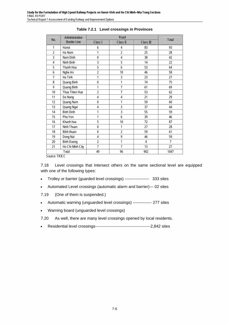
Study for the Formulation of High Speed Railway Projects on Hanoi–Vinh and Ho Chi Minh–Nha Trang Sections FINAL REPORT Technical Report 1 Assessment of Existing Railway and Improvement Options
7-6
Table 7.2.1 Level crossings in Provinces
No. Administrative Border Line
Road Total
Class I Class II Class III
1 Hanoi 6 4 83 93 2 Ha Nam 1 2 25 28 3 Nam Dinh 0 4 38 42 4 Ninh Binh 3 5 14 22 5 Thanh Hoa 5 6 53 64 6 Nghe An 2 10 46 58 7 Ha Tinh 1 3 23 27 8 Quang Binh 0 1 74 75 9 Quang Binh 1 7 61 69 10 Thua Thien Hue 2 7 53 62 11 Da Nang 4 4 21 29 12 Quang Nam 0 1 59 60 13 Quang Ngai 4 3 37 44 14 Binh Dinh 1 3 55 59 15 Phu Yen 1 6 39 46 16 Khanh hoa 5 10 72 87 17 Ninh Thuan 0 1 27 28 18 BInh thuan 0 2 59 61 19 Dong Nai 4 9 46 59 20 Binh Duong 2 1 4 7 21 Ho Chi Minh City 7 7 13 27
Total 49 96 902 1047 Source: TRICC
7.18 Level crossings that intersect others on the same sectional level are equipped with one of the following types:
Trolley or barrier (guarded level crossings) ------------------ 333 sites
Automated Level crossings (automatic alarm and barrier)--- 02 sites
7.19 (One of them is suspended.)
Automatic warning (unguarded level crossings) -------------- 277 sites
Warning board (unguarded level crossings)
7.20 As well, there are many level crossings opened by local residents.
Residential level crossings-----------------------------------------2,842 sites
Study for the Formulation of High Speed Railway Projects on Hanoi–Vinh and Ho Chi Minh–Nha Trang Sections FINAL REPORT
Technical Report 1 Assessment of Existing Railway and Improvement Options
7-7
7.3 Option B-1
1) General
7.21 As for signaling and telecommunication systems in option B-1, electric interlocking devices will be adopted to upgrade the safety and maintainability of the line and multiple block systems will be employed to strengthen the transport capacity. Automatic train protection system (ATP) with speed checking function will be adopted to prevent drivers from train operating error. Centralized traffic control system will be installed to arrange the train operations effectively overall line. Automated level crossings with alarm warning and automatic barrier function will be installed in the 1,047 sites to upgrade the safety in the level crossings. As for a backbone network, synchronous digital hierarchy (SDH) system will be installed.
7.22 The train radio system provides wireless communication not only between dispatchers in the operation control center (OCC) and train crew but also between the dispatchers and operating and maintenance (O & M) staff.
2) Signaling System
7.23 Option B-1 is to strengthen the transport capacity and increase in maximum operating speed to 120 kph in double tracking (1,000 gauges) with frequency of approximately 190 trains per day.
(1) Block System and Train Detection
7.24 To enhance the transport capacity, it is necessary to run more trains in term of frequency. The average distance between stations from Hanoi to Saigon is 10.48km. Three (3) block sections will be installed between stations on average. The length of a block section will be approximately 3.5km on average. Train locations between stations will be detected by using continuous track circuits.
(2) Signal System and Automatic Train Protection
7.25 The color lighted fixed signal will be used and the automatic train protection system with speed checking function will be adopted to prevent the train from exceeding the maximum operating speed of 120 km/h.
(3) Interlocking Devices for Stations
7.26 Electric interlocking devices will be proposed as interlocking devices for stations. Train locations in the stations will be detected using continuous track circuits. Electrical switch machine will be employed to turn points in the stations.
(4) Automated Level Crossing
7.27 Automated level crossings with alarm warning and automatic barrier function will be installed in the 1,047 sites to upgrade the safety, excluding level crossings opened by local residents.
(5) Operation Control Center (OCC) and Centralized Traffic Control System (CTC)
7.28 Operation Control Center will be installed in Hanoi and Ho Chi Minh City to monitor and control train operations for 1,726 km of railways. The OCCs will be equipped with central equipment of CTC and the stations with local equipment of CTC.
Study for the Formulation of High Speed Railway Projects on Hanoi–Vinh and Ho Chi Minh–Nha Trang Sections FINAL REPORT Technical Report 1 Assessment of Existing Railway and Improvement Options
7-8
(6) Other Signaling Works
7.29 Electrical power will be supplied from the nearest transmission lines of Electricity of Vietnam (EVN). In case of no EVN transmission line near the railway, the transmission lines for power supply to signaling equipment will be installed along the railway lines. The OCCs and stations will be equipped with stand-by electrical power generator and uninterruptible power system (UPS).
3) Telecommunication System
(1) Telecommunication Systems Stated below are Installed for B – 1
Back-bone Network System (Synchronous digital hierarchy (SDH) nodes)
Train Radio System
Cables for telecommunication lines
Automatic Telephone System
Dispatch Telephone System
Dedicated Telephone System
Block Telephone System
Wayside Telephone System
Public Address System
Passenger Information system
Electric Clock System
Wayside Disaster Prevention system
Power Supply Equipment
(2) Synchronous Digital Hierarchy (SDH) Nodes
The Synchronous Transfer Module-16(STM-16) nodes are installed at the OCC and main stations.
The Synchronous Transfer Module-1(STM-1) nodes are installed at the intermediate stations between main stations to form a branch network.
(3) Train Radio System
The train radio system provides wireless communication not only between dispatchers in the operation control center (OCC) and train crew but also
between the dispatchers and operating and maintenance (O & M) staff. It also provides wireless voice and data communication channels to support the operation, failure recovery and maintenance requirements of the railway systems.
The section of Hanoi–Ho Chi Minh City will be equipped with wireless communication system due to a little tunnel sections. The tunnel sections will be equipped with Leaky Coaxial cable (LCX).
Optical fiber transmission lines are used to connect the central radio equipment and base radio stations.
Study for the Formulation of High Speed Railway Projects on Hanoi–Vinh and Ho Chi Minh–Nha Trang Sections FINAL REPORT
Technical Report 1 Assessment of Existing Railway and Improvement Options
7-9
7.4 Option B-2
1) General
7.30 As for signaling and telecommunication systems in option B-2, they are similar to the systems in B-1. The most different are not including automated level crossings due to grade separation, and including signaling equipment (ex. Impedance bonds) and shield cables immune to electro-magnetic induction by AC electrification of the line. Optical fiber cables immune to electro-magnetic induction by AC electrification will be adopted as backbone network system for railway telecommunication.
2) Signaling System
7.31 B-2 is to strengthen the transport capacity and increase in maximum operating speed to 150 kph in double tracking (1,435 gauge) with frequency of approximately 140 trains per day. In B-2, grade separation in the intersection between railways and roads and electrification of railways will be adopted. Accordingly, automated level crossings will be no necessary and the signaling and telecommunication systems for AC electrification of railway will be needed.
(1) Block System and Train Detection
7.32 It is necessary to run multiple trains between stations to increase in frequency of trains operating between stations so as to strengthen the transport capacity of the line. The average distance between stations from Hanoi to Saigon is 10.48km. Three (3) block sections will be installed between stations on average. The distance of a block section will be approximately 3.5km long on average. Train location between stations will be detected using divided –multiple frequency track circuits for electrification of the railways.
(2) Signal System and Automatic Train Protection
7.33 Color lighted fixed signal will be proposed in accordance with the maximum operating speed of 150 kph and automatic train protection system with speed checking function will be adopted.
(3) Interlocking Devices for Stations
7.34 Electric interlocking devices will be proposed as interlocking devices for stations. Train locations in the stations will be detected using continuous AF track circuits. Electrical switch machine will be employed to turn points in the stations.
(4) Operation Control Center (OCC) and Centralized Traffic Control System (CTC)
7.35 Operation Control Center will be installed in Hanoi and Ho Chi Minh City to monitor and control train operations for 1,726km of railways. The OCCs will be equipped with central equipment of CTC and the stations with local equipment of CTC.
(5) Other Signaling Works
7.36 Electrical power will be supplied from the nearest transmission lines of Electricity of
7.37 Vietnam (EVN). In case of no EVN transmission line near the railway, the transmission lines for power supply to signaling equipment will be installed along the railway lines. The OCCs and stations will be equipped with stand-by electrical power generator and uninterruptible power system (UPS).
Study for the Formulation of High Speed Railway Projects on Hanoi–Vinh and Ho Chi Minh–Nha Trang Sections FINAL REPORT Technical Report 1 Assessment of Existing Railway and Improvement Options
7-10
3) Telecommunication System
7.38 Telecommunication systems stated below are installed for B-2.
Back-bone Network System(Synchronous digital hierarchy (SDH) nodes)
Train Radio System
Cables for telecommunication lines
Automatic Telephone System
Dispatch Telephone System
Dedicated Telephone System
Block Telephone System
Wayside Telephone System
Public address system
Passenger Information System
Electric Clock System
Wayside Disaster Prevention system
Power Supply Equipment
4) Signaling and Telecommunication Equipment Immune to AC Electrification of Railways
Divided –multiple frequency track circuits, impedance bonds and other signaling equipment immune to electro-magnetic induction by AC electrification of railways will be adopted.
Optical fiber cables immune to immune to electro-magnetic induction by AC electrification of railways will be adopted as backbone network system for railway telecommunication.
Signaling and telecommunication shielded cables immune to electro-magnetic induction by AC electrification of railways will be adopted along the railways.
Study for the Formulation of High Speed Railway Projects on Hanoi–Vinh and Ho Chi Minh–Nha Trang Sections FINAL REPORT
Technical Report 1 Assessment of Existing Railway and Improvement Options
8-1
8 ROLLING STOCK
8.1 Option A-1
8.1 In Option A-1, the train timetable and the number of trains are the same as present. Therefore, any additional investment for rolling stock is unnecessary.
8.2 Option A-2
1) General
8.2 In option A-2, the number of trains will be increase but the train speed is the same as present. Therefore, most rolling stock which VR owns now can be used in option A-2. New investment is needed for the rolling stock which still run short. The specs of new rolling stock are assumed to be equal to existing rolling stock. New locomotives should be the same type as present D19E.
2) Basis for Calculation
26 trains on Hanoi–Saigon section will be divided to 14 passenger trains and 12 freight trains.
The other trains on other sections are all passenger trains.
All passenger train sets have 15 passenger cars.
All freight train sets have 35 freight cars.
All locomotives are used for both passenger trains and freight trains.
All rolling stocks are maintained under VR maintenance system.
Diesel locomotive needs to refuel within 1,000km operation.
Refueling locomotive takes about 3 hours.
The station for change locomotives.
− Trains between Hanoi–Saigon: Dong Hoi, Da Nang, Dieu Tri
− Trains between Vinh–Dieu Tri: Da Nang
− Trains between Hue–Saigon: Dieu Tri
− Other trains do not change locomotive.
3) Required Rolling Stocks on Operation
8.3 The number of required rolling stocks on operation is estimated by rolling stock operation chart considered in each section. The number is shown below tables 8.2.1, 8.2.2, 8.2.3 and 8.2.4.
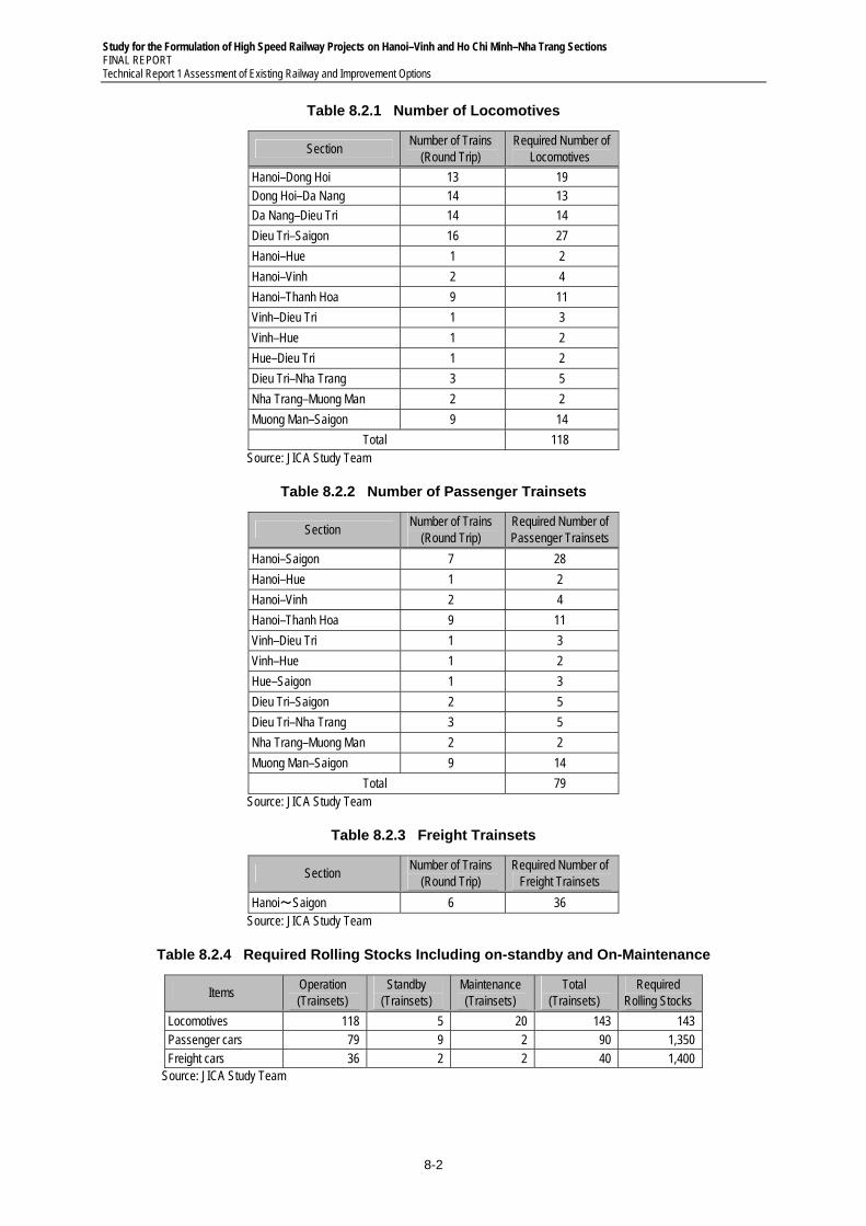
Study for the Formulation of High Speed Railway Projects on Hanoi–Vinh and Ho Chi Minh–Nha Trang Sections FINAL REPORT Technical Report 1 Assessment of Existing Railway and Improvement Options
8-2
Table 8.2.1 Number of Locomotives
Section Number of Trains
(Round Trip) Required Number of
Locomotives
Hanoi–Dong Hoi 13 19 Dong Hoi–Da Nang 14 13
Da Nang–Dieu Tri 14 14
Dieu Tri–Saigon 16 27
Hanoi–Hue 1 2
Hanoi–Vinh 2 4
Hanoi–Thanh Hoa 9 11
Vinh–Dieu Tri 1 3
Vinh–Hue 1 2
Hue–Dieu Tri 1 2
Dieu Tri–Nha Trang 3 5
Nha Trang–Muong Man 2 2
Muong Man–Saigon 9 14
Total 118 Source: JICA Study Team
Table 8.2.2 Number of Passenger Trainsets
Section Number of Trains
(Round Trip) Required Number of Passenger Trainsets
Hanoi–Saigon 7 28
Hanoi–Hue 1 2
Hanoi–Vinh 2 4
Hanoi–Thanh Hoa 9 11
Vinh–Dieu Tri 1 3
Vinh–Hue 1 2
Hue–Saigon 1 3
Dieu Tri–Saigon 2 5
Dieu Tri–Nha Trang 3 5
Nha Trang–Muong Man 2 2
Muong Man–Saigon 9 14
Total 79 Source: JICA Study Team
Table 8.2.3 Freight Trainsets
Section Number of Trains
(Round Trip) Required Number of
Freight Trainsets
Hanoi~Saigon 6 36 Source: JICA Study Team
Table 8.2.4 Required Rolling Stocks Including on-standby and On-Maintenance
Items Operation (Trainsets)
Standby (Trainsets)
Maintenance (Trainsets)
Total (Trainsets)
Required Rolling Stocks
Locomotives 118 5 20 143 143 Passenger cars 79 9 2 90 1,350 Freight cars 36 2 2 40 1,400
Source: JICA Study Team
Study for the Formulation of High Speed Railway Projects on Hanoi–Vinh and Ho Chi Minh–Nha Trang Sections FINAL REPORT
Technical Report 1 Assessment of Existing Railway and Improvement Options
8-3
8.3 Option B-1
1) General
8.4 In option B-1, the speed of passenger trains will be increased to 120 km/h. Therefore, Locomotives and passenger cars for passenger trains should be purchased. Existing D19E and D20E locomotives and freight cars could be applied to freight trains.
2) Major Technical Specification of New Rolling Stocks
Locomotive for passenger train
− Diesel - Electric Locomotive
− Capacity ≧ 1,920kW
− Design speed ≧ 120 km/h
Passenger car
− Design speed ≧ 120 km/h
− Passenger Capacity : 1,000 / trainset
3) Basis for Calculation
62 freight trains go through Hanoi–Saigon section. The other freight trains run on Hanoi–Da-Nang Section
All passenger trainsets have 15 passenger cars
All freight trainsets have 35 freight cars
Locomotives are maintained under Japanese maintenance system as below
− Monthly Inspection (1day): Every 90 days
− Bogie Inspection or Overhaul maintenance(40 days): Every 600,000 km
Passenger and Freight cars are maintained under VR maintenance system.
The station for change locomotives
− Passenger Trains between Hanoi–Saigon: Da Nang
− Freight Trains between Hanoi–Saigon: Dong Hoi, Da Nang, Dieu Tri
− Other trains do not change locomotive.
4) Required Rolling Stocks on Operation
8.5 The number of required rolling stocks on operation is estimated by rolling stock operation chart considered in each section. The number is shown in Table 8.3.1, Table 8.3.2, Table 8.3.3, Table 8.3.4 and Table 8.3.5.
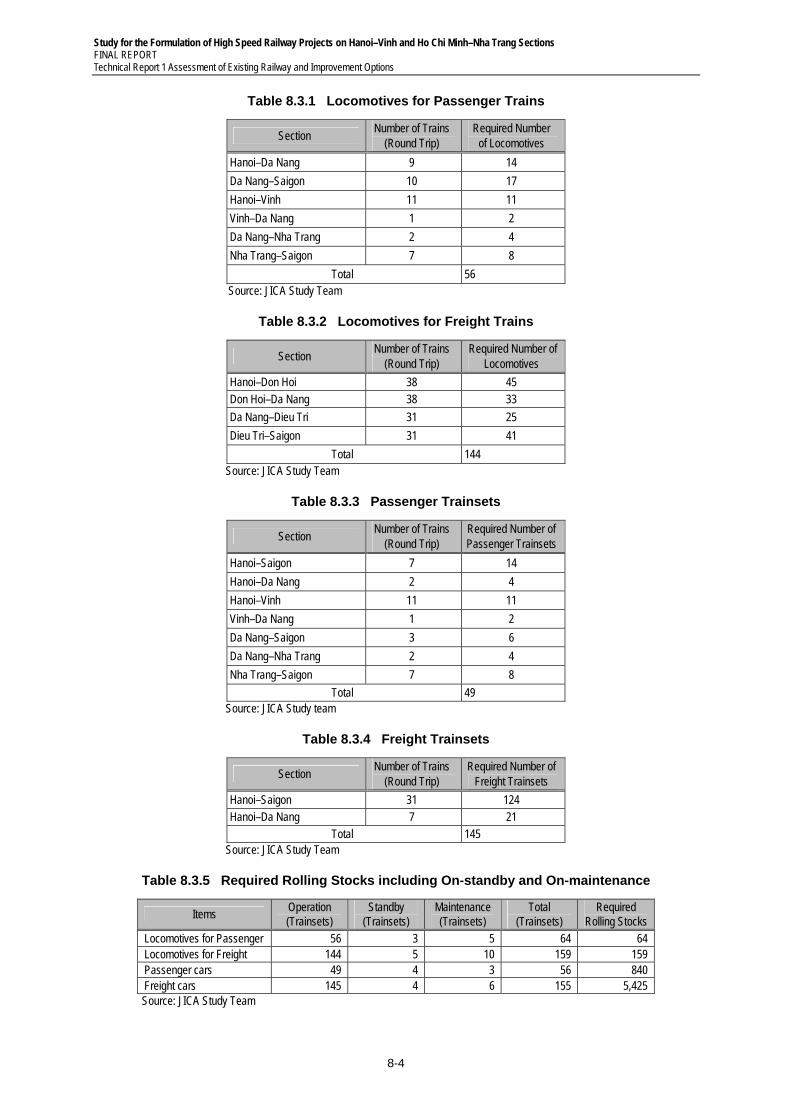
Study for the Formulation of High Speed Railway Projects on Hanoi–Vinh and Ho Chi Minh–Nha Trang Sections FINAL REPORT Technical Report 1 Assessment of Existing Railway and Improvement Options
8-4
Table 8.3.1 Locomotives for Passenger Trains
Section Number of Trains
(Round Trip) Required Number
of Locomotives
Hanoi–Da Nang 9 14
Da Nang–Saigon 10 17
Hanoi–Vinh 11 11
Vinh–Da Nang 1 2
Da Nang–Nha Trang 2 4
Nha Trang–Saigon 7 8
Total 56 Source: JICA Study Team
Table 8.3.2 Locomotives for Freight Trains
Section Number of Trains
(Round Trip) Required Number of
Locomotives
Hanoi–Don Hoi 38 45 Don Hoi–Da Nang 38 33
Da Nang–Dieu Tri 31 25
Dieu Tri–Saigon 31 41
Total 144 Source: JICA Study Team
Table 8.3.3 Passenger Trainsets
Section Number of Trains
(Round Trip) Required Number of Passenger Trainsets
Hanoi–Saigon 7 14
Hanoi–Da Nang 2 4
Hanoi–Vinh 11 11
Vinh–Da Nang 1 2
Da Nang–Saigon 3 6
Da Nang–Nha Trang 2 4
Nha Trang–Saigon 7 8
Total 49 Source: JICA Study team
Table 8.3.4 Freight Trainsets
Section Number of Trains
(Round Trip) Required Number of
Freight Trainsets
Hanoi–Saigon 31 124 Hanoi–Da Nang 7 21
Total 145 Source: JICA Study Team
Table 8.3.5 Required Rolling Stocks including On-standby and On-maintenance
Items Operation (Trainsets)
Standby (Trainsets)
Maintenance (Trainsets)
Total (Trainsets)
Required Rolling Stocks
Locomotives for Passenger 56 3 5 64 64 Locomotives for Freight 144 5 10 159 159 Passenger cars 49 4 3 56 840 Freight cars 145 4 6 155 5,425 Source: JICA Study Team
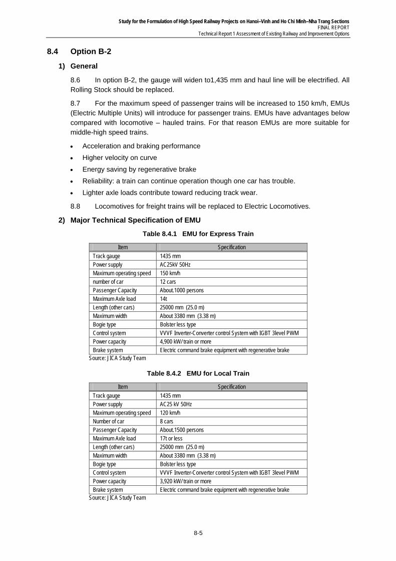
Study for the Formulation of High Speed Railway Projects on Hanoi–Vinh and Ho Chi Minh–Nha Trang Sections FINAL REPORT
Technical Report 1 Assessment of Existing Railway and Improvement Options
8-5
8.4 Option B-2
1) General
8.6 In option B-2, the gauge will widen to1,435 mm and haul line will be electrified. All Rolling Stock should be replaced.
8.7 For the maximum speed of passenger trains will be increased to 150 km/h, EMUs (Electric Multiple Units) will introduce for passenger trains. EMUs have advantages below compared with locomotive – hauled trains. For that reason EMUs are more suitable for middle-high speed trains.
Acceleration and braking performance
Higher velocity on curve
Energy saving by regenerative brake
Reliability: a train can continue operation though one car has trouble.
Lighter axle loads contribute toward reducing track wear.
8.8 Locomotives for freight trains will be replaced to Electric Locomotives.
2) Major Technical Specification of EMU
Table 8.4.1 EMU for Express Train
Item Specification
Track gauge 1435 mm Power supply AC25kV 50Hz Maximum operating speed 150 km/h number of car 12 cars Passenger Capacity About.1000 persons Maximum Axle load 14t Length (other cars) 25000 mm (25.0 m) Maximum width About 3380 mm (3.38 m) Bogie type Bolster less type Control system VVVF Inverter-Converter control System with IGBT 3level PWM Power capacity 4,900 kW/ train or more Brake system Electric command brake equipment with regenerative brake
Source: JICA Study Team
Table 8.4.2 EMU for Local Train
Item Specification
Track gauge 1435 mm Power supply AC25 kV 50Hz Maximum operating speed 120 km/h Number of car 8 cars Passenger Capacity About.1500 persons Maximum Axle load 17t or less Length (other cars) 25000 mm (25.0 m) Maximum width About 3380 mm (3.38 m) Bogie type Bolster less type Control system VVVF Inverter-Converter control System with IGBT 3level PWM Power capacity 3,920 kW/ train or more Brake system Electric command brake equipment with regenerative brake
Source: JICA Study Team
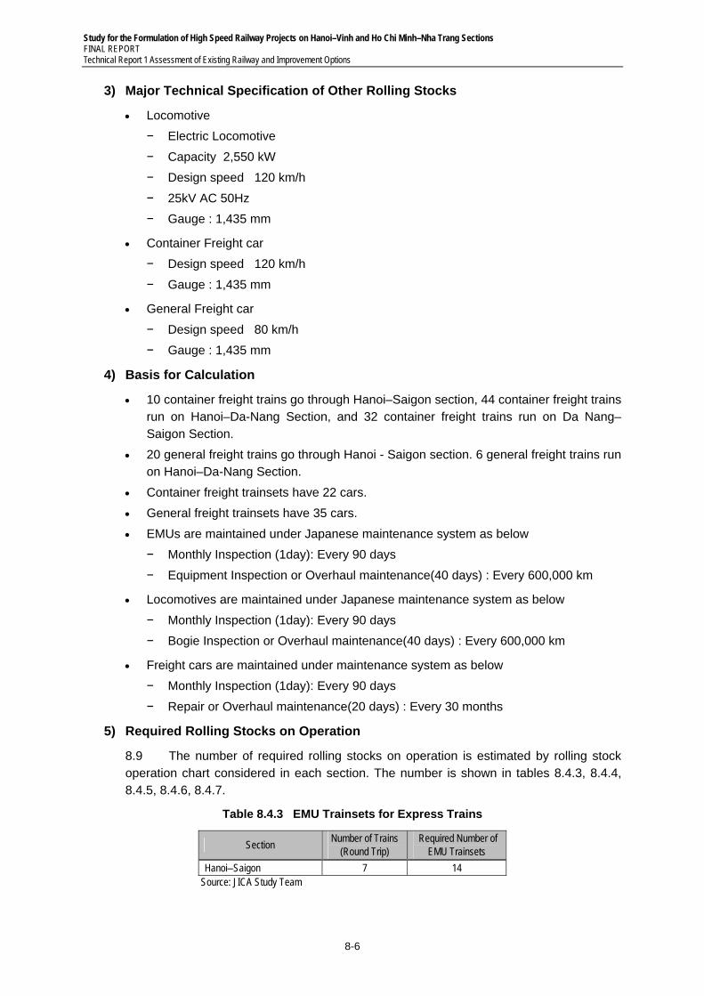
Study for the Formulation of High Speed Railway Projects on Hanoi–Vinh and Ho Chi Minh–Nha Trang Sections FINAL REPORT Technical Report 1 Assessment of Existing Railway and Improvement Options
8-6
3) Major Technical Specification of Other Rolling Stocks
Locomotive
− Electric Locomotive
− Capacity 2,550 kW
− Design speed 120 km/h
− 25kV AC 50Hz
− Gauge : 1,435 mm
Container Freight car
− Design speed 120 km/h
− Gauge : 1,435 mm
General Freight car
− Design speed 80 km/h
− Gauge : 1,435 mm
4) Basis for Calculation
10 container freight trains go through Hanoi–Saigon section, 44 container freight trains run on Hanoi–Da-Nang Section, and 32 container freight trains run on Da Nang–Saigon Section.
20 general freight trains go through Hanoi - Saigon section. 6 general freight trains run on Hanoi–Da-Nang Section.
Container freight trainsets have 22 cars.
General freight trainsets have 35 cars.
EMUs are maintained under Japanese maintenance system as below
− Monthly Inspection (1day): Every 90 days
− Equipment Inspection or Overhaul maintenance(40 days) : Every 600,000 km
Locomotives are maintained under Japanese maintenance system as below
− Monthly Inspection (1day): Every 90 days
− Bogie Inspection or Overhaul maintenance(40 days) : Every 600,000 km
Freight cars are maintained under maintenance system as below
− Monthly Inspection (1day): Every 90 days
− Repair or Overhaul maintenance(20 days) : Every 30 months
5) Required Rolling Stocks on Operation
8.9 The number of required rolling stocks on operation is estimated by rolling stock operation chart considered in each section. The number is shown in tables 8.4.3, 8.4.4, 8.4.5, 8.4.6, 8.4.7.
Table 8.4.3 EMU Trainsets for Express Trains
Section Number of Trains
(Round Trip) Required Number of
EMU Trainsets
Hanoi–Saigon 7 14 Source: JICA Study Team
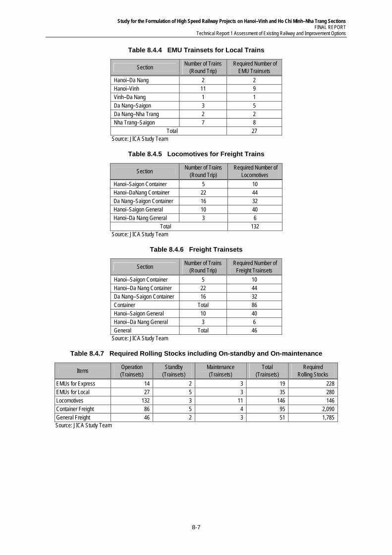
Study for the Formulation of High Speed Railway Projects on Hanoi–Vinh and Ho Chi Minh–Nha Trang Sections FINAL REPORT
Technical Report 1 Assessment of Existing Railway and Improvement Options
8-7
Table 8.4.4 EMU Trainsets for Local Trains
Section Number of Trains
(Round Trip) Required Number of
EMU Trainsets
Hanoi–Da Nang 2 2 Hanoi–Vinh 11 9 Vinh–Da Nang 1 1 Da Nang–Saigon 3 5 Da Nang–Nha Trang 2 2 Nha Trang–Saigon 7 8
Total 27 Source: JICA Study Team
Table 8.4.5 Locomotives for Freight Trains
Section Number of Trains
(Round Trip) Required Number of
Locomotives
Hanoi–Saigon Container 5 10 Hanoi–DaNang Container 22 44 Da Nang–Saigon Container 16 32 Hanoi–Saigon General 10 40 Hanoi–Da Nang General 3 6
Total 132 Source: JICA Study Team
Table 8.4.6 Freight Trainsets
Section Number of Trains
(Round Trip) Required Number of
Freight Trainsets
Hanoi–Saigon Container 5 10 Hanoi–Da Nang Container 22 44 Da Nang–Saigon Container 16 32 Container Total 86 Hanoi–Saigon General 10 40 Hanoi–Da Nang General 3 6 General Total 46
Source: JICA Study Team
Table 8.4.7 Required Rolling Stocks including On-standby and On-maintenance
Items Operation (Trainsets)
Standby (Trainsets)
Maintenance (Trainsets)
Total (Trainsets)
Required Rolling Stocks
EMUs for Express 14 2 3 19 228 EMUs for Local 27 5 3 35 280 Locomotives 132 3 11 146 146 Container Freight 86 5 4 95 2,090 General Freight 46 2 3 51 1,785 Source: JICA Study Team
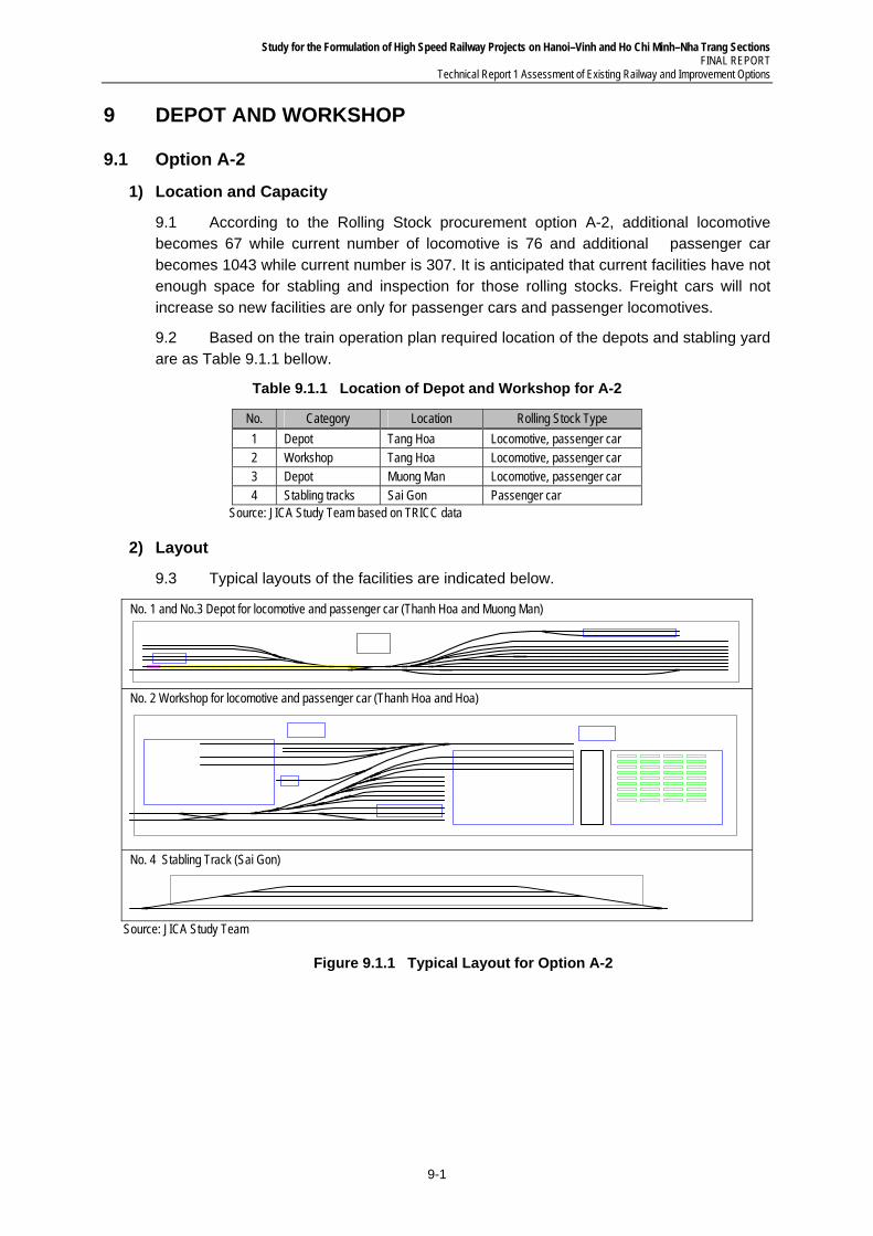
Study for the Formulation of High Speed Railway Projects on Hanoi–Vinh and Ho Chi Minh–Nha Trang Sections FINAL REPORT
Technical Report 1 Assessment of Existing Railway and Improvement Options
9-1
9 DEPOT AND WORKSHOP
9.1 Option A-2
1) Location and Capacity
9.1 According to the Rolling Stock procurement option A-2, additional locomotive becomes 67 while current number of locomotive is 76 and additional passenger car becomes 1043 while current number is 307. It is anticipated that current facilities have not enough space for stabling and inspection for those rolling stocks. Freight cars will not increase so new facilities are only for passenger cars and passenger locomotives.
9.2 Based on the train operation plan required location of the depots and stabling yard are as Table 9.1.1 bellow.
Table 9.1.1 Location of Depot and Workshop for A-2
No. Category Location Rolling Stock Type
1 Depot Tang Hoa Locomotive, passenger car 2 Workshop Tang Hoa Locomotive, passenger car 3 Depot Muong Man Locomotive, passenger car 4 Stabling tracks Sai Gon Passenger car
Source: JICA Study Team based on TRICC data
2) Layout
9.3 Typical layouts of the facilities are indicated below.
No. 1 and No.3 Depot for locomotive and passenger car (Thanh Hoa and Muong Man)
No. 2 Workshop for locomotive and passenger car (Thanh Hoa and Hoa)
No. 4 Stabling Track (Sai Gon)
Source: JICA Study Team
Figure 9.1.1 Typical Layout for Option A-2
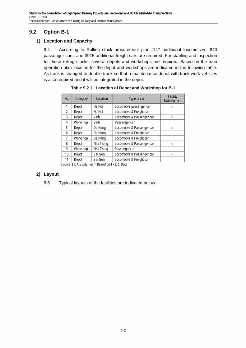
Study for the Formulation of High Speed Railway Projects on Hanoi–Vinh and Ho Chi Minh–Nha Trang Sections FINAL REPORT Technical Report 1 Assessment of Existing Railway and Improvement Options
9-2
9.2 Option B-1
1) Location and Capacity
9.4 According to Rolling stock procurement plan, 147 additional locomotives, 840 passenger cars, and 3915 additional freight cars are required. For stabling and inspection for these rolling stocks, several depots and workshops are required. Based on the train operation plan location for the depot and workshops are indicated in the following table. As track is changed to double track so that a maintenance depot with track work vehicles is also required and it will be integrated in the depot.
Table 9.2.1 Location of Depot and Workshop for B-1
No. Category Location Type of car Facility
Maintenance
1 Depot Ha Noi Locomotive passenger car ○ 2 Depot Ha Noi Locomotive & Freight car 3 Depot Vinh Locomotive & Passenger car ○ 4 Workshop Vinh Passenger car 5 Depot Da Nang Locomotive & Passenger car ○ 6 Depot Da Nang Locomotive & Freight car 7 Workshop Da Nang Locomotive & Freight car 8 Depot Nha Trang Locomotive & Passenger car ○ 9 Workshop Nha Trang Passenger car 10 Depot Sai Gon Locomotive & Passenger car ○ 11 Depot Sai Gon Locomotive & Freight car
Source: JICA Study Team Based on TRICC Data
2) Layout
9.5 Typical layouts of the facilities are indicated below.
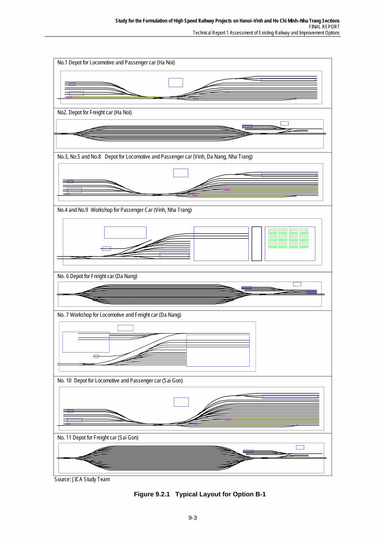
Study for the Formulation of High Speed Railway Projects on Hanoi–Vinh and Ho Chi Minh–Nha Trang Sections FINAL REPORT
Technical Report 1 Assessment of Existing Railway and Improvement Options
9-3
No.1 Depot for Locomotive and Passenger car (Ha Noi)
No2. Depot for Freight car (Ha Noi)
No.3, No.5 and No.8 Depot for Locomotive and Passenger car (Vinh, Da Nang, Nha Trang)
No.4 and No.9 Workshop for Passenger Car (Vinh, Nha Trang)
No. 6 Depot for Freight car (Da Nang)
No. 7 Workshop for Locomotive and Freight car (Da Nang)
No. 10 Depot for Locomotive and Passenger car (Sai Gon)
No. 11 Depot for Freight car (Sai Gon)
Source: JICA Study Team
Figure 9.2.1 Typical Layout for Option B-1
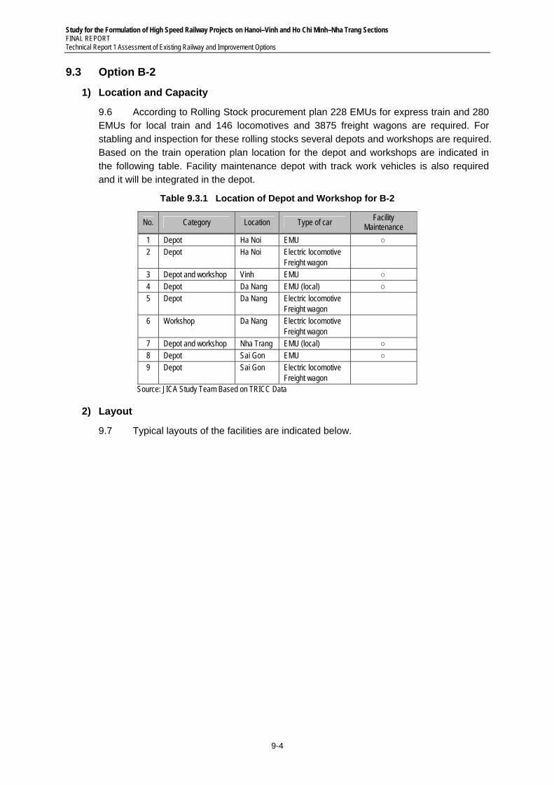
Study for the Formulation of High Speed Railway Projects on Hanoi–Vinh and Ho Chi Minh–Nha Trang Sections FINAL REPORT Technical Report 1 Assessment of Existing Railway and Improvement Options
9-4
9.3 Option B-2
1) Location and Capacity
9.6 According to Rolling Stock procurement plan 228 EMUs for express train and 280 EMUs for local train and 146 locomotives and 3875 freight wagons are required. For stabling and inspection for these rolling stocks several depots and workshops are required. Based on the train operation plan location for the depot and workshops are indicated in the following table. Facility maintenance depot with track work vehicles is also required and it will be integrated in the depot.
Table 9.3.1 Location of Depot and Workshop for B-2
No. Category Location Type of car Facility
Maintenance
1 Depot Ha Noi EMU ○ 2 Depot Ha Noi Electric locomotive
Freight wagon
3 Depot and workshop Vinh EMU ○ 4 Depot Da Nang EMU (local) ○ 5 Depot Da Nang Electric locomotive
Freight wagon
6 Workshop Da Nang Electric locomotive Freight wagon
7 Depot and workshop Nha Trang EMU (local) ○ 8 Depot Sai Gon EMU ○ 9 Depot Sai Gon Electric locomotive
Freight wagon
Source: JICA Study Team Based on TRICC Data
2) Layout
9.7 Typical layouts of the facilities are indicated below.
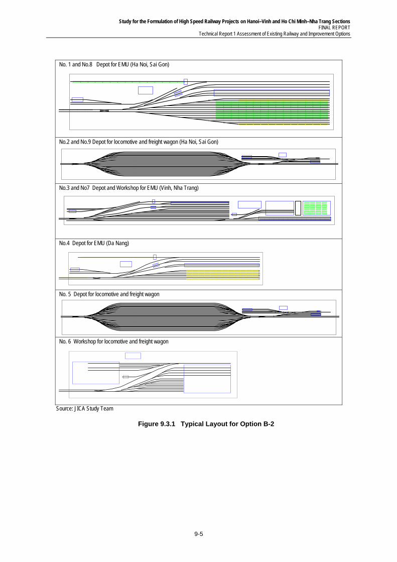
Study for the Formulation of High Speed Railway Projects on Hanoi–Vinh and Ho Chi Minh–Nha Trang Sections FINAL REPORT
Technical Report 1 Assessment of Existing Railway and Improvement Options
9-5
No. 1 and No.8 Depot for EMU (Ha Noi, Sai Gon)
No.2 and No.9 Depot for locomotive and freight wagon (Ha Noi, Sai Gon)
No.3 and No7 Depot and Workshop for EMU (Vinh, Nha Trang)
No.4 Depot for EMU (Da Nang)
No. 5 Depot for locomotive and freight wagon
No. 6 Workshop for locomotive and freight wagon
Source: JICA Study Team
Figure 9.3.1 Typical Layout for Option B-2
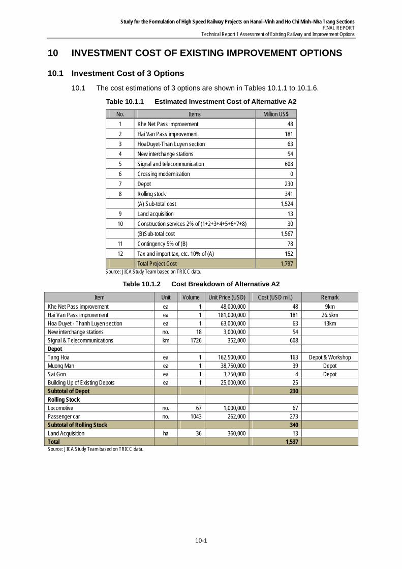
Study for the Formulation of High Speed Railway Projects on Hanoi–Vinh and Ho Chi Minh–Nha Trang Sections FINAL REPORT
Technical Report 1 Assessment of Existing Railway and Improvement Options
10-1
10 INVESTMENT COST OF EXISTING IMPROVEMENT OPTIONS
10.1 Investment Cost of 3 Options
10.1 The cost estimations of 3 options are shown in Tables 10.1.1 to 10.1.6.
Table 10.1.1 Estimated Investment Cost of Alternative A2
No. Items Million US$
1 Khe Net Pass improvement 48
2 Hai Van Pass improvement 181
3 HoaDuyet-Than Luyen section 63
4 New interchange stations 54
5 Signal and telecommunication 608
6 Crossing modernization 0
7 Depot 230
8 Rolling stock 341
(A) Sub-total cost 1,524
9 Land acquisition 13
10 Construction services 2% of (1+2+3+4+5+6+7+8) 30
(B)Sub-total cost 1,567
11 Contingency 5% of (B) 78
12 Tax and import tax, etc. 10% of (A) 152
Total Project Cost 1,797 Source: JICA Study Team based on TRICC data.
Table 10.1.2 Cost Breakdown of Alternative A2
Item Unit Volume Unit Price (USD) Cost (USD mil.) Remark
Khe Net Pass improvement ea 1 48,000,000 48 9km Hai Van Pass improvement ea 1 181,000,000 181 26.5km Hoa Duyet - Thanh Luyen section ea 1 63,000,000 63 13km New interchange stations no. 18 3,000,000 54
Signal & Telecommunications km 1726 352,000 608
Depot
Tang Hoa ea 1 162,500,000 163 Depot & Workshop Muong Man ea 1 38,750,000 39 Depot Sai Gon ea 1 3,750,000 4 Depot Building Up of Existing Depots ea 1 25,000,000 25
Subtotal of Depot
230
Rolling Stock
Locomotive no. 67 1,000,000 67
Passenger car no. 1043 262,000 273
Subtotal of Rolling Stock
340
Land Acquisition ha 36 360,000 13
Total
1,537
Source: JICA Study Team based on TRICC data.
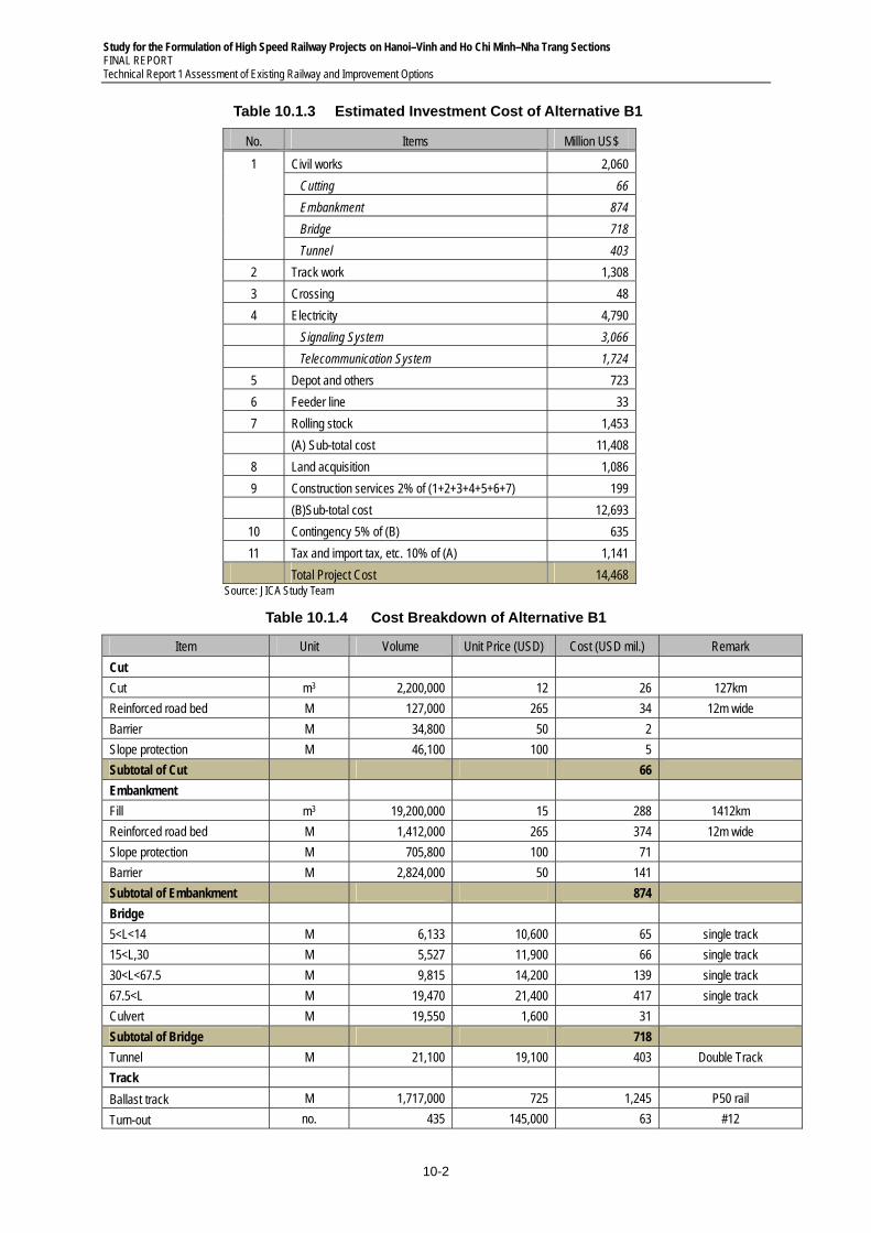
Study for the Formulation of High Speed Railway Projects on Hanoi–Vinh and Ho Chi Minh–Nha Trang Sections FINAL REPORT Technical Report 1 Assessment of Existing Railway and Improvement Options
10-2
Table 10.1.3 Estimated Investment Cost of Alternative B1
No. Items Million US$
1 Civil works 2,060
Cutting 66
Embankment 874
Bridge 718
Tunnel 403
2 Track work 1,308
3 Crossing 48
4 Electricity 4,790
Signaling System 3,066
Telecommunication System 1,724
5 Depot and others 723
6 Feeder line 33
7 Rolling stock 1,453
(A) Sub-total cost 11,408
8 Land acquisition 1,086
9 Construction services 2% of (1+2+3+4+5+6+7) 199
(B)Sub-total cost 12,693
10 Contingency 5% of (B) 635
11 Tax and import tax, etc. 10% of (A) 1,141
Total Project Cost 14,468 Source: JICA Study Team
Table 10.1.4 Cost Breakdown of Alternative B1
Item Unit Volume Unit Price (USD) Cost (USD mil.) Remark
Cut
Cut m3 2,200,000 12 26 127km
Reinforced road bed M 127,000 265 34 12m wide
Barrier M 34,800 50 2
Slope protection M 46,100 100 5
Subtotal of Cut
66
Embankment
Fill m3 19,200,000 15 288 1412km
Reinforced road bed M 1,412,000 265 374 12m wide
Slope protection M 705,800 100 71
Barrier M 2,824,000 50 141
Subtotal of Embankment
874
Bridge
5<L<14 M 6,133 10,600 65 single track
15<L,30 M 5,527 11,900 66 single track
30<L<67.5 M 9,815 14,200 139 single track
67.5<L M 19,470 21,400 417 single track
Culvert M 19,550 1,600 31
Subtotal of Bridge
718
Tunnel M 21,100 19,100 403 Double Track
Track
Ballast track M 1,717,000 725 1,245 P50 rail
Turn-out no. 435 145,000 63 #12
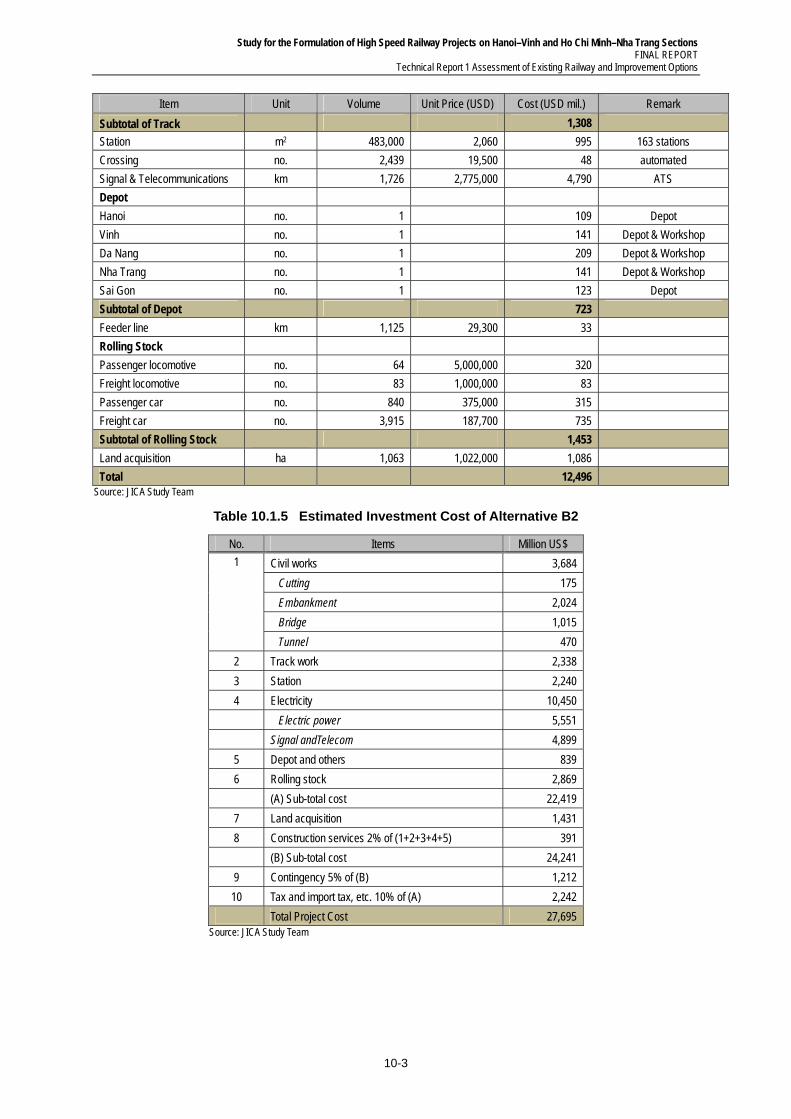
Study for the Formulation of High Speed Railway Projects on Hanoi–Vinh and Ho Chi Minh–Nha Trang Sections FINAL REPORT
Technical Report 1 Assessment of Existing Railway and Improvement Options
10-3
Item Unit Volume Unit Price (USD) Cost (USD mil.) Remark
Subtotal of Track
1,308
Station m2 483,000 2,060 995 163 stations
Crossing no. 2,439 19,500 48 automated
Signal & Telecommunications km 1,726 2,775,000 4,790 ATS
Depot
Hanoi no. 1 109 Depot
Vinh no. 1 141 Depot & Workshop
Da Nang no. 1 209 Depot & Workshop
Nha Trang no. 1 141 Depot & Workshop
Sai Gon no. 1 123 Depot
Subtotal of Depot
723
Feeder line km 1,125 29,300 33
Rolling Stock
Passenger locomotive no. 64 5,000,000 320
Freight locomotive no. 83 1,000,000 83
Passenger car no. 840 375,000 315
Freight car no. 3,915 187,700 735
Subtotal of Rolling Stock
1,453
Land acquisition ha 1,063 1,022,000 1,086
Total
12,496
Source: JICA Study Team
Table 10.1.5 Estimated Investment Cost of Alternative B2
No. Items Million US$
1 Civil works 3,684
Cutting 175
Embankment 2,024
Bridge 1,015
Tunnel 470
2 Track work 2,338
3 Station 2,240
4 Electricity 10,450
Electric power 5,551
Signal andTelecom 4,899
5 Depot and others 839
6 Rolling stock 2,869
(A) Sub-total cost 22,419
7 Land acquisition 1,431
8 Construction services 2% of (1+2+3+4+5) 391
(B) Sub-total cost 24,241
9 Contingency 5% of (B) 1,212
10 Tax and import tax, etc. 10% of (A) 2,242
Total Project Cost 27,695 Source: JICA Study Team
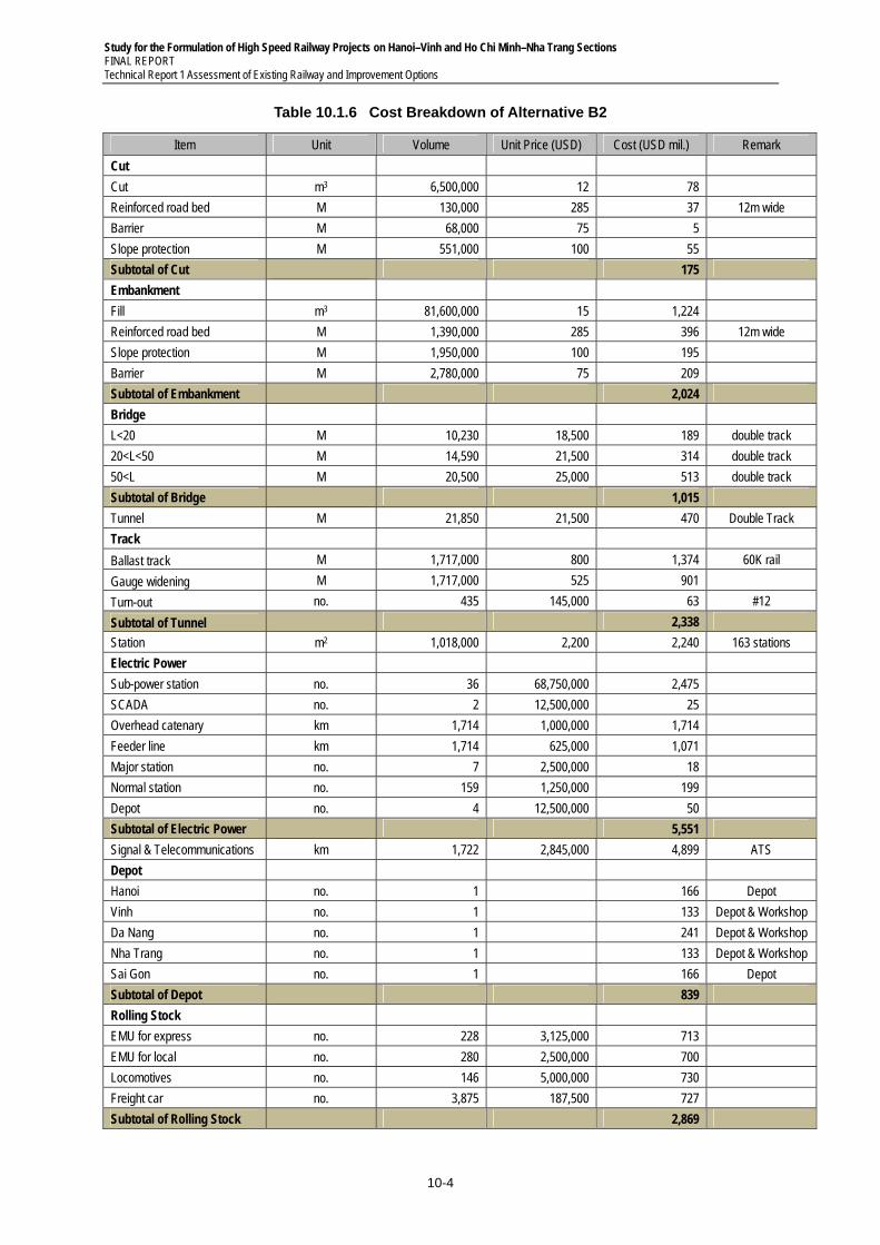
Study for the Formulation of High Speed Railway Projects on Hanoi–Vinh and Ho Chi Minh–Nha Trang Sections FINAL REPORT Technical Report 1 Assessment of Existing Railway and Improvement Options
10-4
Table 10.1.6 Cost Breakdown of Alternative B2
Item Unit Volume Unit Price (USD) Cost (USD mil.) Remark
Cut
Cut m3 6,500,000 12 78
Reinforced road bed M 130,000 285 37 12m wide
Barrier M 68,000 75 5
Slope protection M 551,000 100 55
Subtotal of Cut
175
Embankment
Fill m3 81,600,000 15 1,224
Reinforced road bed M 1,390,000 285 396 12m wide
Slope protection M 1,950,000 100 195
Barrier M 2,780,000 75 209
Subtotal of Embankment
2,024
Bridge
L<20 M 10,230 18,500 189 double track
20<L<50 M 14,590 21,500 314 double track
50<L M 20,500 25,000 513 double track
Subtotal of Bridge
1,015
Tunnel M 21,850 21,500 470 Double Track
Track
Ballast track M 1,717,000 800 1,374 60K rail
Gauge widening M 1,717,000 525 901
Turn-out no. 435 145,000 63 #12
Subtotal of Tunnel
2,338
Station m2 1,018,000 2,200 2,240 163 stations
Electric Power
Sub-power station no. 36 68,750,000 2,475
SCADA no. 2 12,500,000 25
Overhead catenary km 1,714 1,000,000 1,714
Feeder line km 1,714 625,000 1,071
Major station no. 7 2,500,000 18
Normal station no. 159 1,250,000 199
Depot no. 4 12,500,000 50
Subtotal of Electric Power
5,551
Signal & Telecommunications km 1,722 2,845,000 4,899 ATS
Depot
Hanoi no. 1 166 Depot
Vinh no. 1 133 Depot & Workshop
Da Nang no. 1 241 Depot & Workshop
Nha Trang no. 1 133 Depot & Workshop
Sai Gon no. 1 166 Depot
Subtotal of Depot
839
Rolling Stock
EMU for express no. 228 3,125,000 713
EMU for local no. 280 2,500,000 700
Locomotives no. 146 5,000,000 730
Freight car no. 3,875 187,500 727
Subtotal of Rolling Stock
2,869
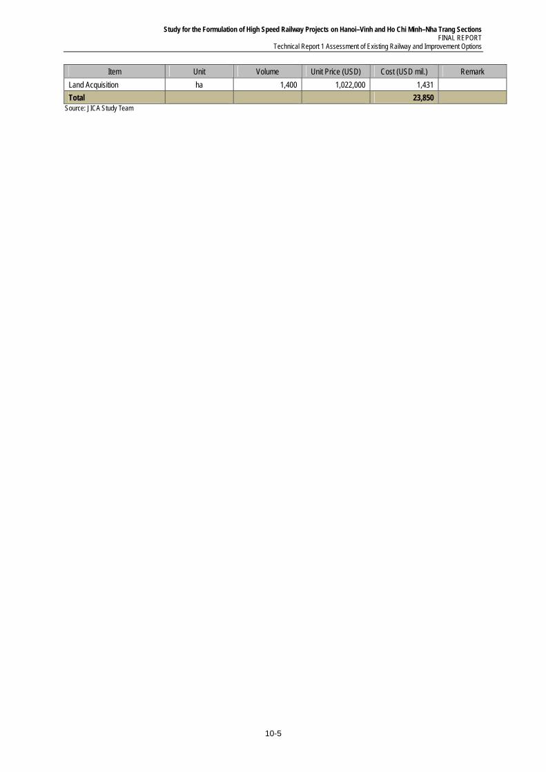
Study for the Formulation of High Speed Railway Projects on Hanoi–Vinh and Ho Chi Minh–Nha Trang Sections FINAL REPORT
Technical Report 1 Assessment of Existing Railway and Improvement Options
10-5
Item Unit Volume Unit Price (USD) Cost (USD mil.) Remark
Land Acquisition ha 1,400 1,022,000 1,431
Total
23,850
Source: JICA Study Team
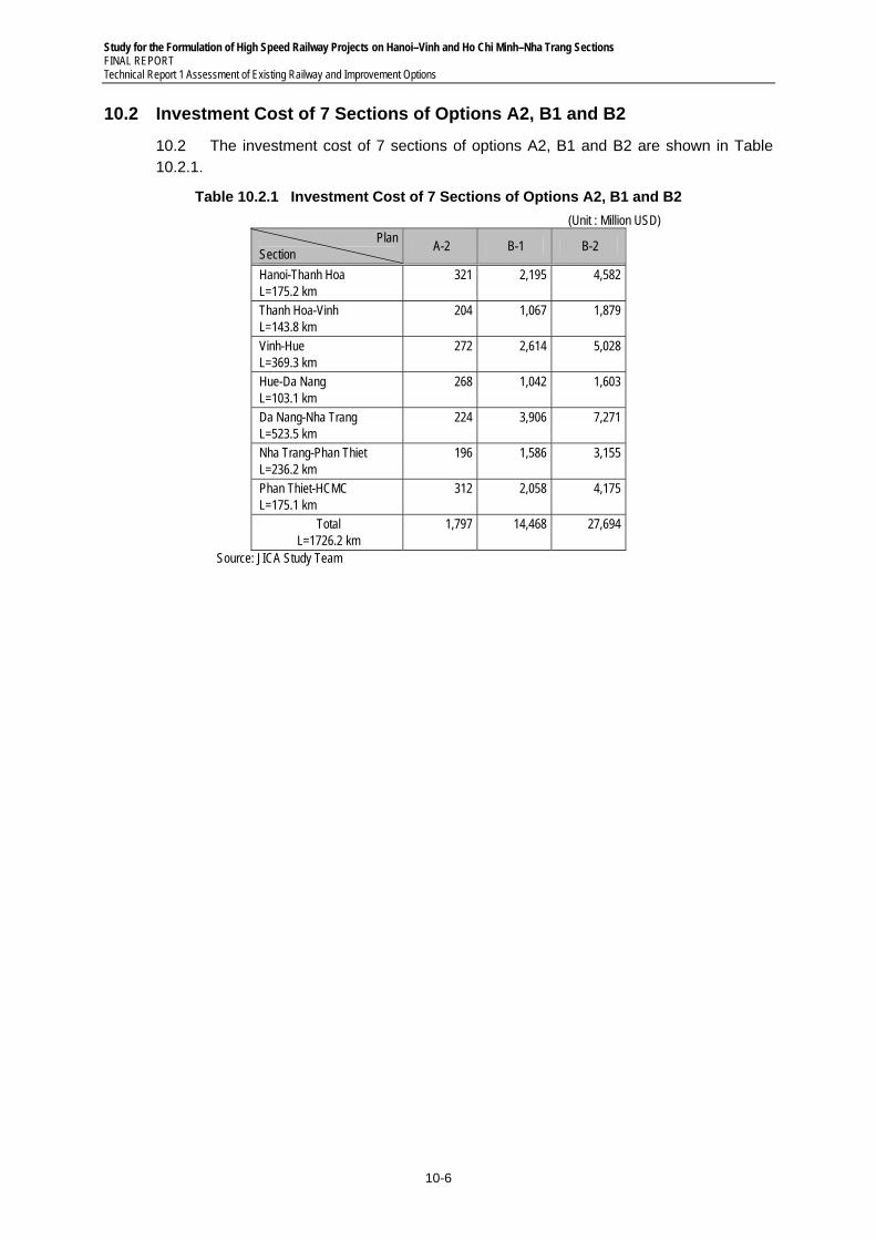
Study for the Formulation of High Speed Railway Projects on Hanoi–Vinh and Ho Chi Minh–Nha Trang Sections FINAL REPORT Technical Report 1 Assessment of Existing Railway and Improvement Options
10-6
10.2 Investment Cost of 7 Sections of Options A2, B1 and B2
10.2 The investment cost of 7 sections of options A2, B1 and B2 are shown in Table 10.2.1.
Table 10.2.1 Investment Cost of 7 Sections of Options A2, B1 and B2
(Unit : Million USD) Plan
Section A-2 B-1 B-2
Hanoi-Thanh Hoa L=175.2 km
321 2,195 4,582
Thanh Hoa-Vinh L=143.8 km
204 1,067 1,879
Vinh-Hue L=369.3 km
272 2,614 5,028
Hue-Da Nang L=103.1 km
268 1,042 1,603
Da Nang-Nha Trang L=523.5 km
224 3,906 7,271
Nha Trang-Phan Thiet L=236.2 km
196 1,586 3,155
Phan Thiet-HCMC L=175.1 km
312 2,058 4,175
Total L=1726.2 km
1,797 14,468 27,694
Source: JICA Study Team


