
Copyright © 2015 James Barone Racing LLC. Any unauthorized reproduction or publication of this document is a strictly prohibited without the written consent from James Barone Racing.
Pag
e1
james Barone Racing
Aftermarket Parts and Accessories
JBR 2007 – 2009 MAZDASPEED 3 Front Mount Intercooler Piping Kit Installation Instructions for TR8 Intercooler
Tooling: o Jack, Jack Stands, Ramps or a Lift
o Ratchet wrench
o 6” socket extension
o 10mm and 12mm sockets
o 10mm and 12mm wrenches
o WD40 or grease
o Philips head screw driver
o Drill and 3/16” drill bit
o Razor knife with new blade
Parts List: o 2” x 2.5” Silicone Reducer Coupler
o Hot Side Black Wrinkle Coated Aluminum Elbow
o Hot Side Polished Aluminum Down Tube
o 90 Degree 2.5” Silicone Elbow
o Hot Side Silicone Core Hose
o Cold Side Silicone Core Hose
o BPV Flange
o 1 – Shielded Hose Clamp
o 1 – 68/60mm T-bolt clamp
o 6 – 75/67mm T-bolt Clamps
o 1 – 81/73mm T-bolt Clamp
o 2 – 6mm – 1.0 x 35mm Stainless Bolts
o 4 – 6mm – 1.0 Nylon Insert Hex Nut Stainless
o 2 – 6mm – Flat Washers Stainless
o 2 – 8mm – 8mm x 1.25 x 20mm Tap Bolts Stainless
o 2 – 8mm – Lock Washers Stainless
o 2 – Core Mounting Angle Brackets
o 1 – Driver’s side power steering Angle Bracket
o 1 – Passenger Side Power Steering Angle Bracket
Copyright © 2015 James Barone Racing LLC. Any unauthorized reproduction or publication of this document is a strictly prohibited without the written consent from James Barone Racing.
Pag
e2
1. Begin by parking on a smooth level surface with the emergency brake engaged. Jack up the front of the vehicle and position jack stands underneath both sides.
Refer to you vehicles owner’s manual for proper jack placement and supporting procedures.
Never get under a vehicle without the proper support in place.
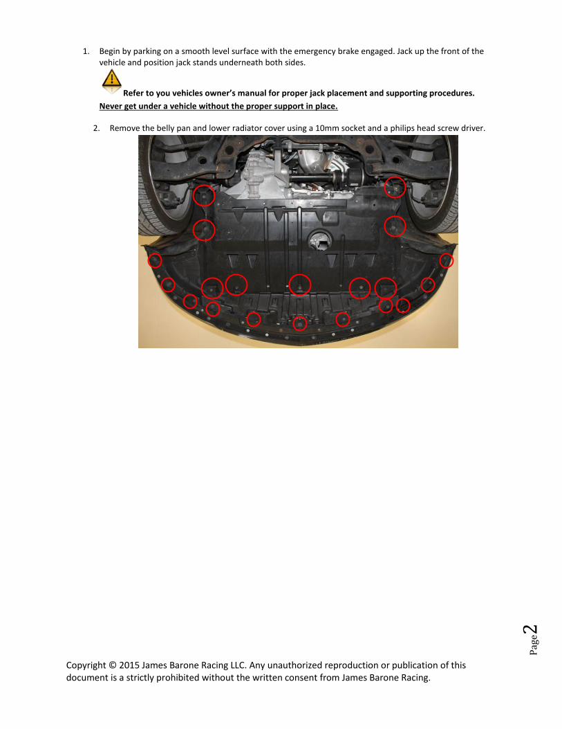
2. Remove the belly pan and lower radiator cover using a 10mm socket and a philips head screw driver.
Copyright © 2015 James Barone Racing LLC. Any unauthorized reproduction or publication of this document is a strictly prohibited without the written consent from James Barone Racing.
Pag
e3
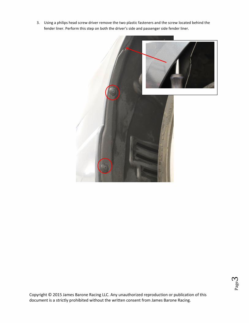
3. Using a philips head screw driver remove the two plastic fasteners and the screw located behind the
fender liner. Perform this step on both the driver’s side and passenger side fender liner.
Copyright © 2015 James Barone Racing LLC. Any unauthorized reproduction or publication of this document is a strictly prohibited without the written consent from James Barone Racing.
Pag
e4
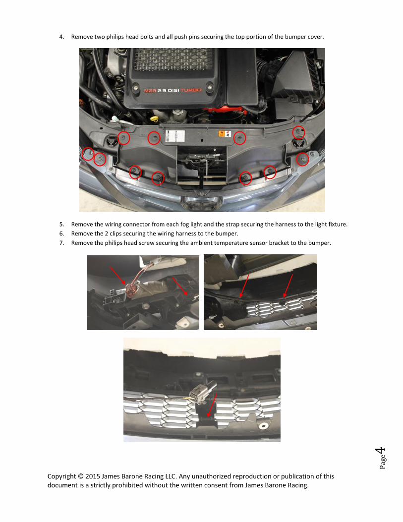
4. Remove two philips head bolts and all push pins securing the top portion of the bumper cover.
5. Remove the wiring connector from each fog light and the strap securing the harness to the light fixture.
6. Remove the 2 clips securing the wiring harness to the bumper.
7. Remove the philips head screw securing the ambient temperature sensor bracket to the bumper.
Copyright © 2015 James Barone Racing LLC. Any unauthorized reproduction or publication of this document is a strictly prohibited without the written consent from James Barone Racing.
Pag
e5
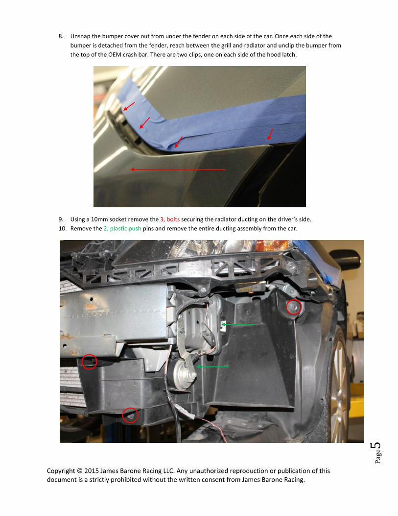
8. Unsnap the bumper cover out from under the fender on each side of the car. Once each side of the
bumper is detached from the fender, reach between the grill and radiator and unclip the bumper from
the top of the OEM crash bar. There are two clips, one on each side of the hood latch.
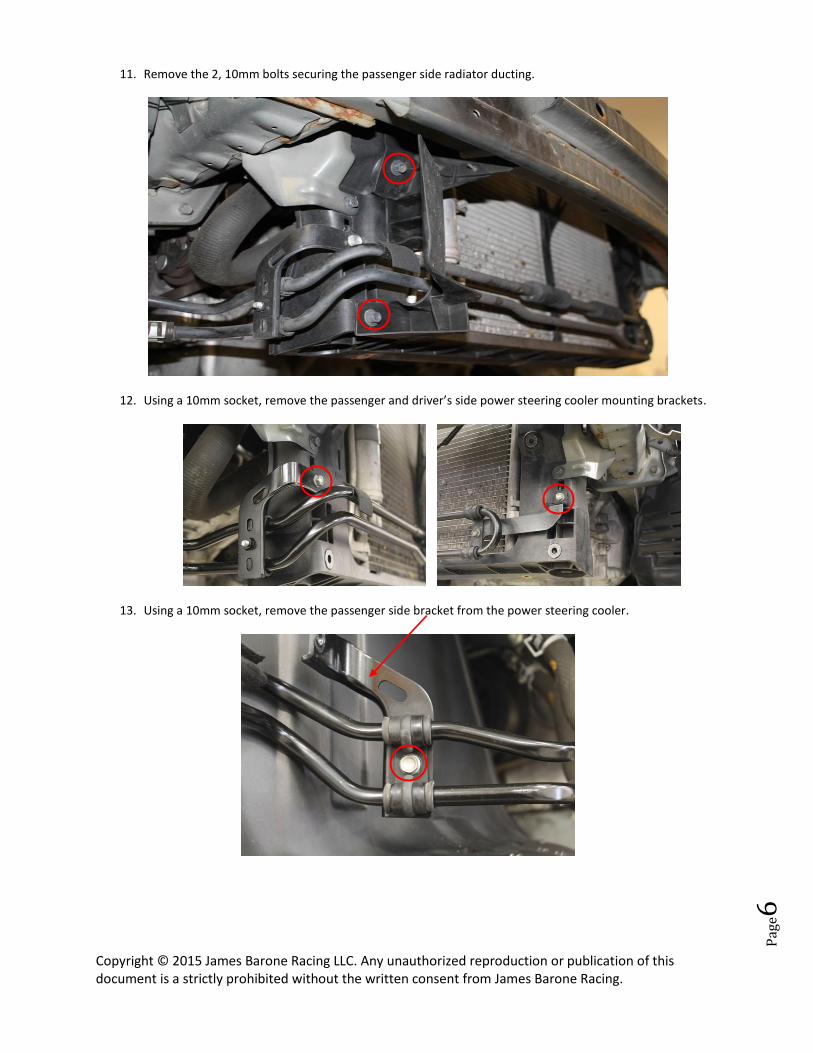
9. Using a 10mm socket remove the 3, bolts securing the radiator ducting on the driver’s side.
10. Remove the 2, plastic push pins and remove the entire ducting assembly from the car.
Copyright © 2015 James Barone Racing LLC. Any unauthorized reproduction or publication of this document is a strictly prohibited without the written consent from James Barone Racing.
Pag
e6
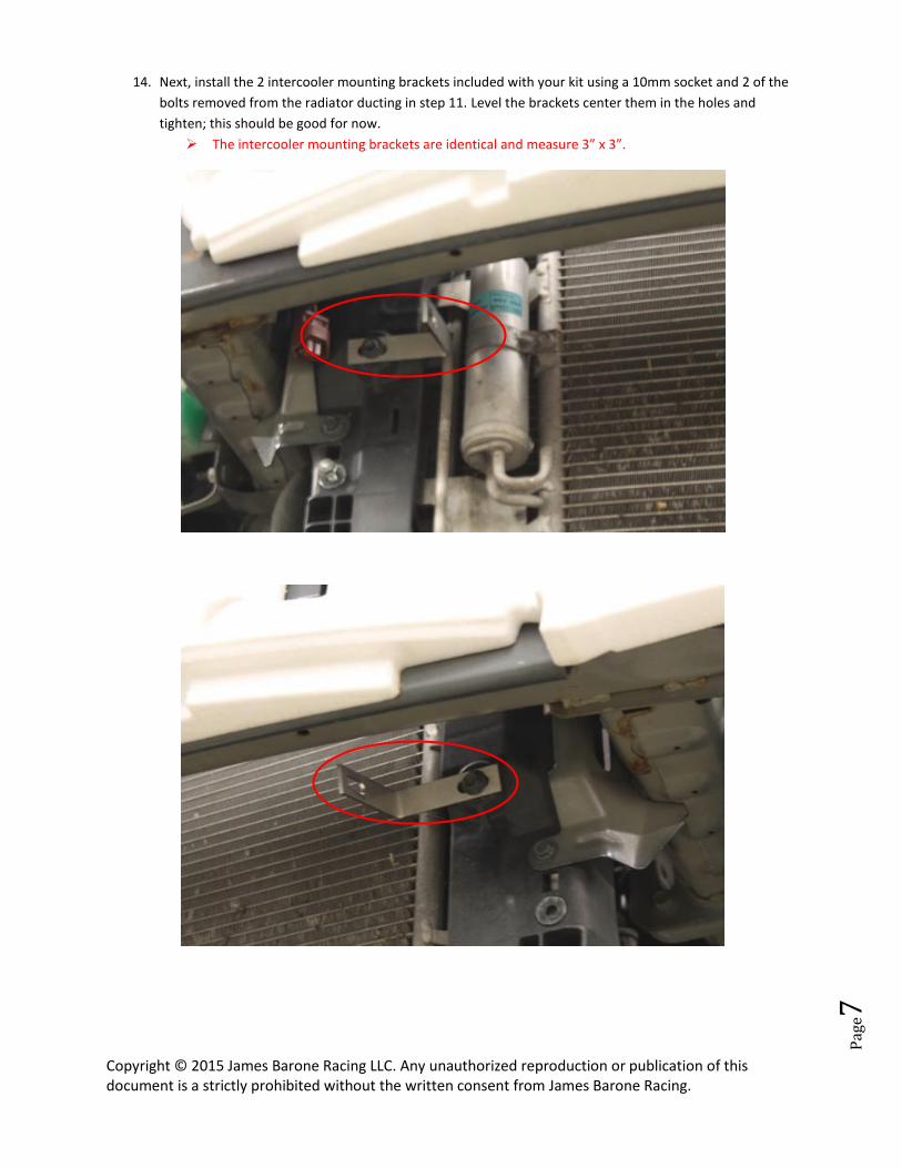
11. Remove the 2, 10mm bolts securing the passenger side radiator ducting.
12. Using a 10mm socket, remove the passenger and driver’s side power steering cooler mounting brackets.
13. Using a 10mm socket, remove the passenger side bracket from the power steering cooler.
Copyright © 2015 James Barone Racing LLC. Any unauthorized reproduction or publication of this document is a strictly prohibited without the written consent from James Barone Racing.
Pag
e7
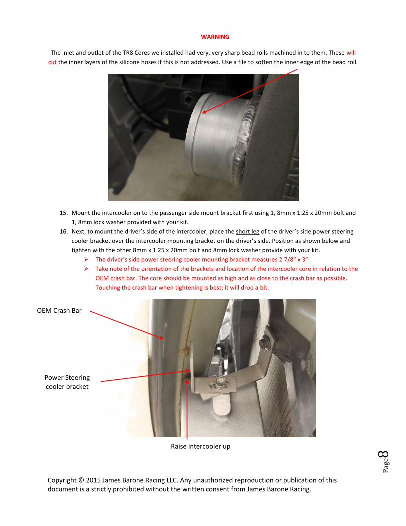
14. Next, install the 2 intercooler mounting brackets included with your kit using a 10mm socket and 2 of the
bolts removed from the radiator ducting in step 11. Level the brackets center them in the holes and
tighten; this should be good for now.
The intercooler mounting brackets are identical and measure 3” x 3”.
Copyright © 2015 James Barone Racing LLC. Any unauthorized reproduction or publication of this document is a strictly prohibited without the written consent from James Barone Racing.
Pag
e8
WARNING
The inlet and outlet of the TR8 Cores we installed had very, very sharp bead rolls machined in to them. These will
cut the inner layers of the silicone hoses if this is not addressed. Use a file to soften the inner edge of the bead roll.
15. Mount the intercooler on to the passenger side mount bracket first using 1, 8mm x 1.25 x 20mm bolt and
1, 8mm lock washer provided with your kit.
16. Next, to mount the driver’s side of the intercooler, place the short leg of the driver’s side power steering
cooler bracket over the intercooler mounting bracket on the driver’s side. Position as shown below and
tighten with the other 8mm x 1.25 x 20mm bolt and 8mm lock washer provide with your kit.
The driver’s side power steering cooler mounting bracket measures 2 7/8” x 3”
Take note of the orientation of the brackets and location of the intercooler core in relation to the
OEM crash bar. The core should be mounted as high and as close to the crash bar as possible.
Touching the crash bar when tightening is best; it will drop a bit.
OEM Crash Bar
Power Steering cooler bracket
Raise intercooler up
Copyright © 2015 James Barone Racing LLC. Any unauthorized reproduction or publication of this document is a strictly prohibited without the written consent from James Barone Racing.
Pag
e9
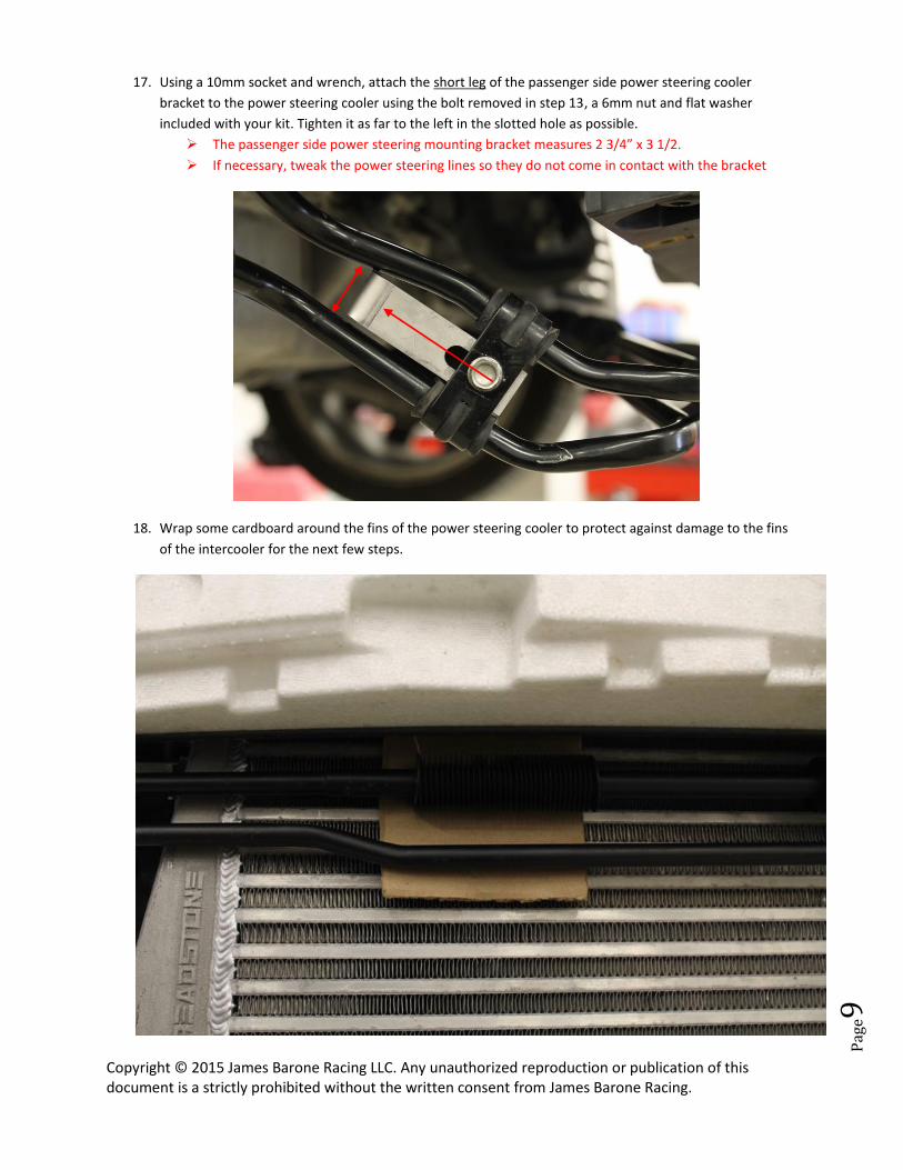
17. Using a 10mm socket and wrench, attach the short leg of the passenger side power steering cooler
bracket to the power steering cooler using the bolt removed in step 13, a 6mm nut and flat washer
included with your kit. Tighten it as far to the left in the slotted hole as possible.
The passenger side power steering mounting bracket measures 2 3/4” x 3 1/2.
If necessary, tweak the power steering lines so they do not come in contact with the bracket
18. Wrap some cardboard around the fins of the power steering cooler to protect against damage to the fins
of the intercooler for the next few steps.
Copyright © 2015 James Barone Racing LLC. Any unauthorized reproduction or publication of this document is a strictly prohibited without the written consent from James Barone Racing.
Pag
e10
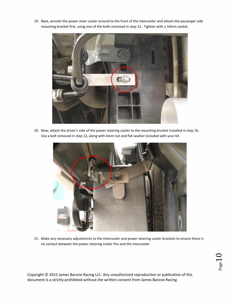
19. Next, wrestle the power steer cooler around to the front of the intercooler and attach the passenger side
mounting bracket first, using one of the bolts removed in step 12. Tighten with a 10mm socket.
20. Now, attach the driver’s side of the power steering cooler to the mounting bracket installed in step 16.
Use a bolt removed in step 12, along with 6mm nut and flat washer included with your kit.
21. Make any necessary adjustments to the intercooler and power steering cooler brackets to ensure there is
no contact between the power steering cooler fins and the intercooler.
Copyright © 2015 James Barone Racing LLC. Any unauthorized reproduction or publication of this document is a strictly prohibited without the written consent from James Barone Racing.
Pag
e11
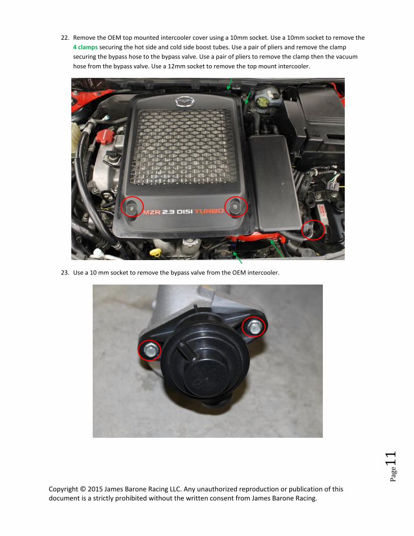
22. Remove the OEM top mounted intercooler cover using a 10mm socket. Use a 10mm socket to remove the
4 clamps securing the hot side and cold side boost tubes. Use a pair of pliers and remove the clamp
securing the bypass hose to the bypass valve. Use a pair of pliers to remove the clamp then the vacuum
hose from the bypass valve. Use a 12mm socket to remove the top mount intercooler.
23. Use a 10 mm socket to remove the bypass valve from the OEM intercooler.
Copyright © 2015 James Barone Racing LLC. Any unauthorized reproduction or publication of this document is a strictly prohibited without the written consent from James Barone Racing.
Pag
e12
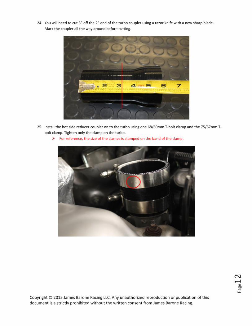
24. You will need to cut 3” off the 2” end of the turbo coupler using a razor knife with a new sharp blade.
Mark the coupler all the way around before cutting.
25. Install the hot side reducer coupler on to the turbo using one 68/60mm T-bolt clamp and the 75/67mm T-
bolt clamp. Tighten only the clamp on the turbo.
For reference, the size of the clamps is stamped on the band of the clamp.
Copyright © 2015 James Barone Racing LLC. Any unauthorized reproduction or publication of this document is a strictly prohibited without the written consent from James Barone Racing.
Pag
e13
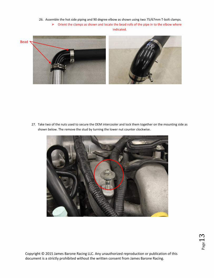
26. Assemble the hot side piping and 90 degree elbow as shown using two 75/67mm T-bolt clamps.
Orient the clamps as shown and locate the bead rolls of the pipe in to the elbow where
indicated.
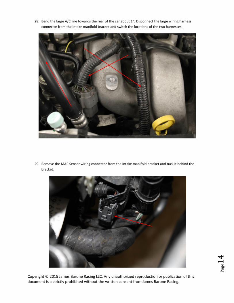
27. Take two of the nuts used to secure the OEM intercooler and lock them together on the mounting side as
shown below. The remove the stud by turning the lower nut counter clockwise.
Bead
Copyright © 2015 James Barone Racing LLC. Any unauthorized reproduction or publication of this document is a strictly prohibited without the written consent from James Barone Racing.
Pag
e14
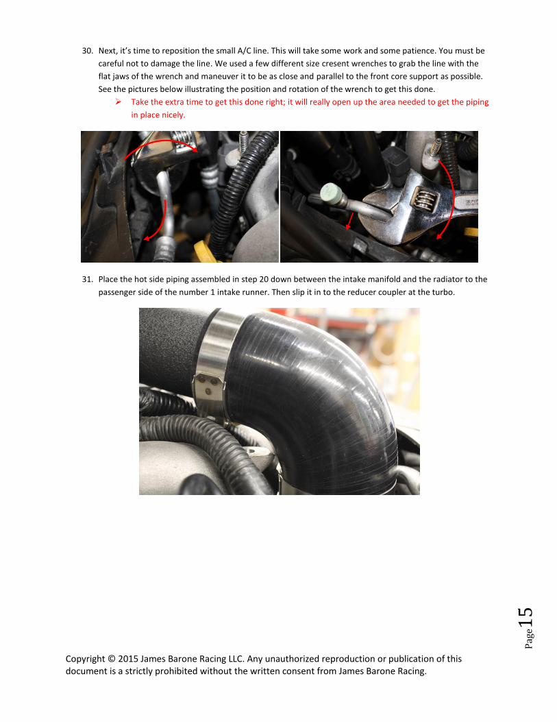
28. Bend the large A/C line towards the rear of the car about 1”. Disconnect the large wiring harness
connector from the intake manifold bracket and switch the locations of the two harnesses.
29. Remove the MAP Sensor wiring connector from the intake manifold bracket and tuck it behind the
bracket.
Copyright © 2015 James Barone Racing LLC. Any unauthorized reproduction or publication of this document is a strictly prohibited without the written consent from James Barone Racing.
Pag
e15
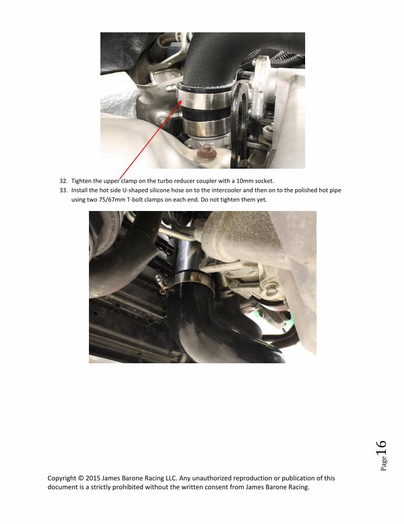
30. Next, it’s time to reposition the small A/C line. This will take some work and some patience. You must be
careful not to damage the line. We used a few different size cresent wrenches to grab the line with the
flat jaws of the wrench and maneuver it to be as close and parallel to the front core support as possible.
See the pictures below illustrating the position and rotation of the wrench to get this done.
Take the extra time to get this done right; it will really open up the area needed to get the piping
in place nicely.
31. Place the hot side piping assembled in step 20 down between the intake manifold and the radiator to the
passenger side of the number 1 intake runner. Then slip it in to the reducer coupler at the turbo.
Copyright © 2015 James Barone Racing LLC. Any unauthorized reproduction or publication of this document is a strictly prohibited without the written consent from James Barone Racing.
Pag
e16
32. Tighten the upper clamp on the turbo reducer coupler with a 10mm socket.
33. Install the hot side U-shaped silicone hose on to the intercooler and then on to the polished hot pipe
using two 75/67mm T-bolt clamps on each end. Do not tighten them yet.
Copyright © 2015 James Barone Racing LLC. Any unauthorized reproduction or publication of this document is a strictly prohibited without the written consent from James Barone Racing.
Pag
e17
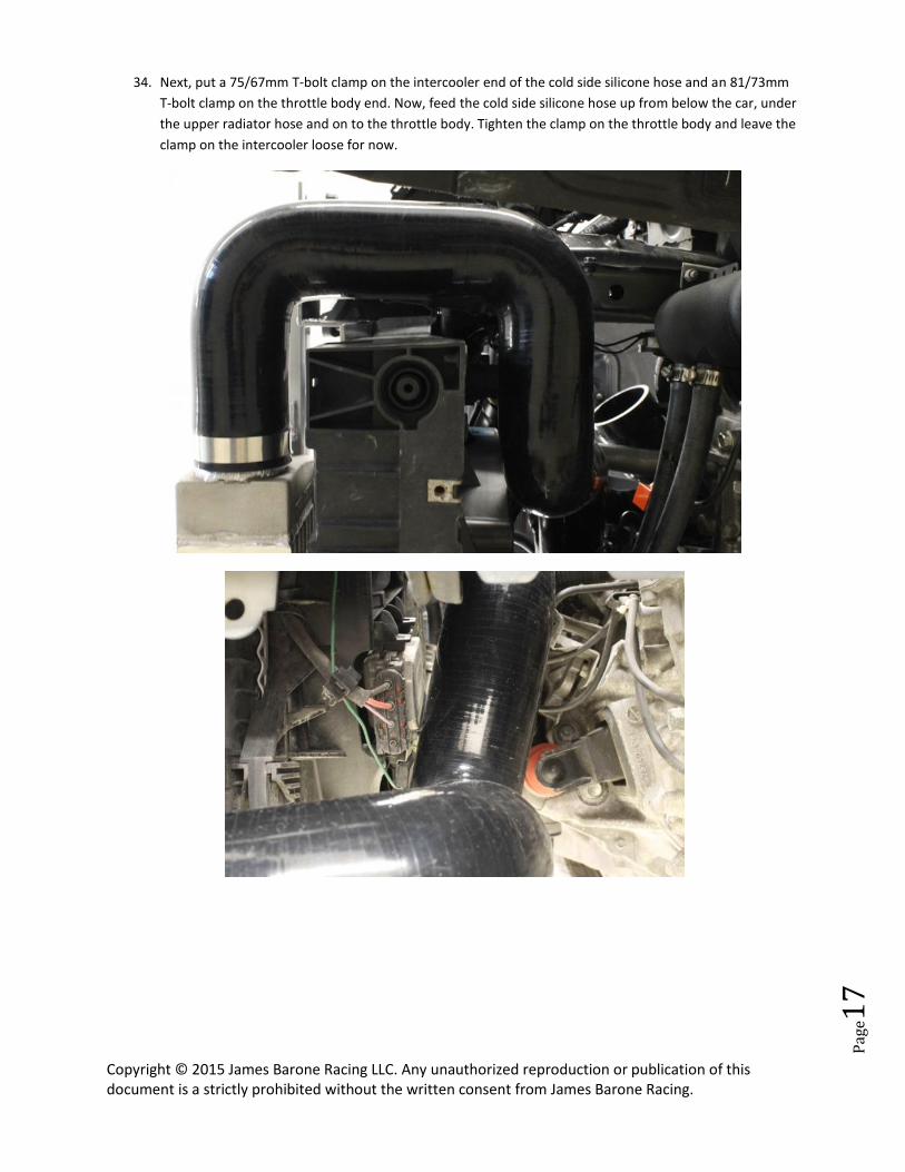
34. Next, put a 75/67mm T-bolt clamp on the intercooler end of the cold side silicone hose and an 81/73mm
T-bolt clamp on the throttle body end. Now, feed the cold side silicone hose up from below the car, under
the upper radiator hose and on to the throttle body. Tighten the clamp on the throttle body and leave the
clamp on the intercooler loose for now.
Copyright © 2015 James Barone Racing LLC. Any unauthorized reproduction or publication of this document is a strictly prohibited without the written consent from James Barone Racing.
Pag
e18
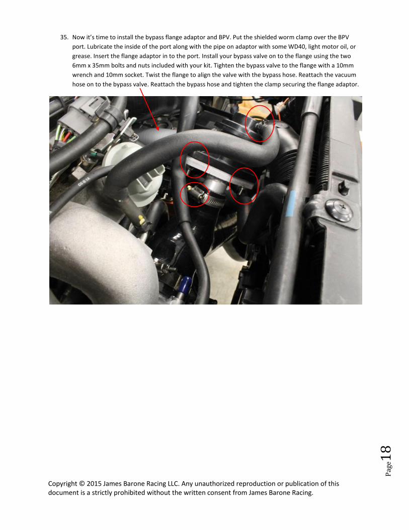
35. Now it’s time to install the bypass flange adaptor and BPV. Put the shielded worm clamp over the BPV
port. Lubricate the inside of the port along with the pipe on adaptor with some WD40, light motor oil, or
grease. Insert the flange adaptor in to the port. Install your bypass valve on to the flange using the two
6mm x 35mm bolts and nuts included with your kit. Tighten the bypass valve to the flange with a 10mm
wrench and 10mm socket. Twist the flange to align the valve with the bypass hose. Reattach the vacuum
hose on to the bypass valve. Reattach the bypass hose and tighten the clamp securing the flange adaptor.
Copyright © 2015 James Barone Racing LLC. Any unauthorized reproduction or publication of this document is a strictly prohibited without the written consent from James Barone Racing.
Pag
e19
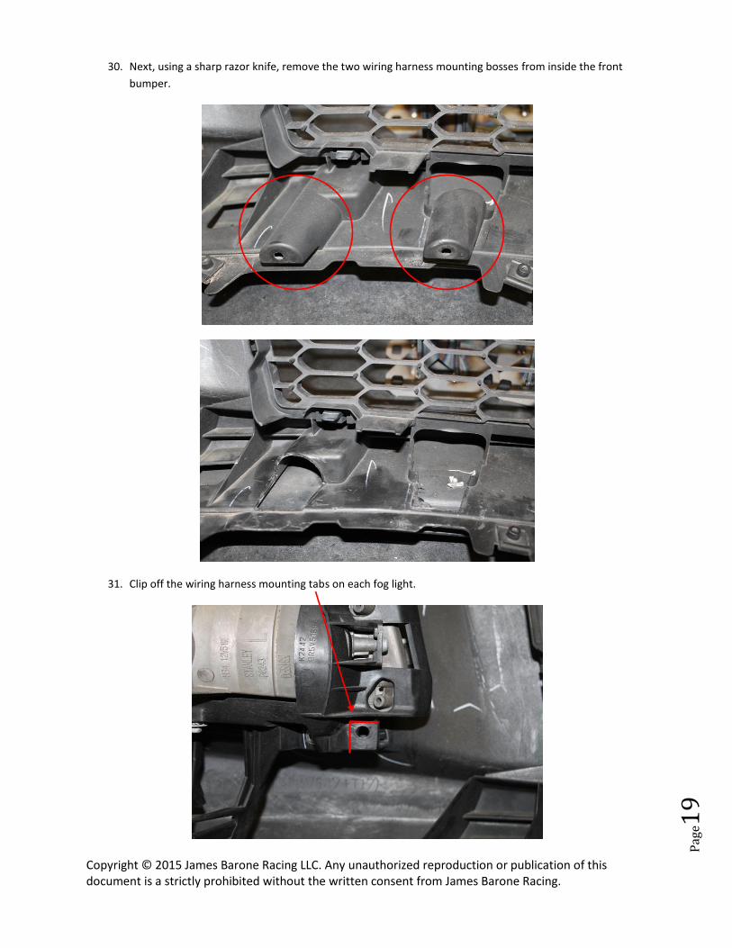
30. Next, using a sharp razor knife, remove the two wiring harness mounting bosses from inside the front
bumper.
31. Clip off the wiring harness mounting tabs on each fog light.
Copyright © 2015 James Barone Racing LLC. Any unauthorized reproduction or publication of this document is a strictly prohibited without the written consent from James Barone Racing.
Pag
e20
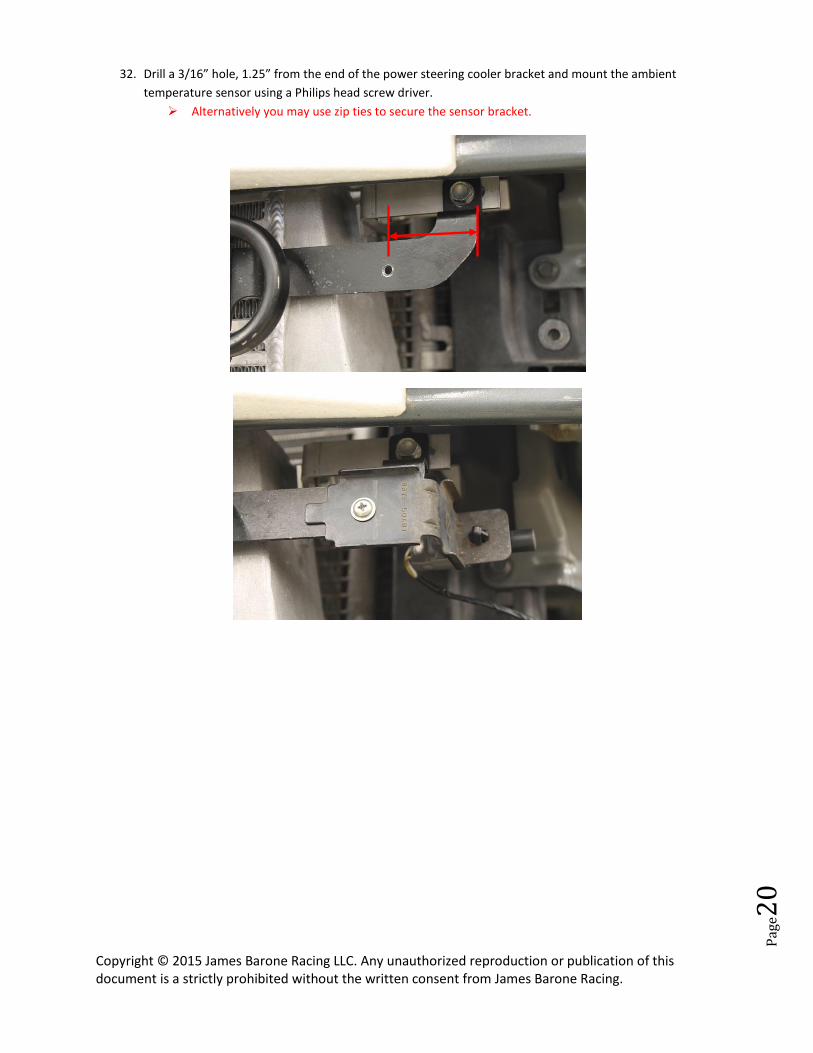
32. Drill a 3/16” hole, 1.25” from the end of the power steering cooler bracket and mount the ambient
temperature sensor using a Philips head screw driver.
Alternatively you may use zip ties to secure the sensor bracket.
Copyright © 2015 James Barone Racing LLC. Any unauthorized reproduction or publication of this document is a strictly prohibited without the written consent from James Barone Racing.
Pag
e21
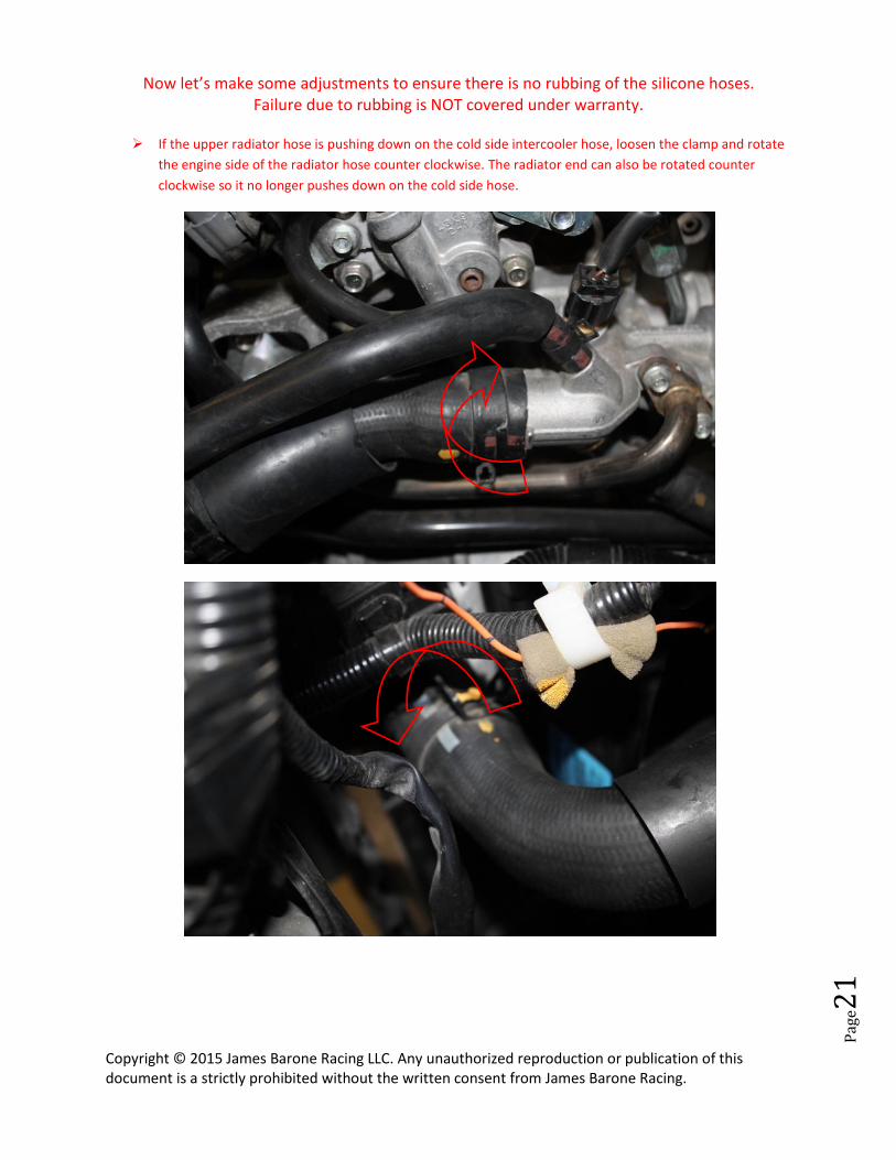
Now let’s make some adjustments to ensure there is no rubbing of the silicone hoses. Failure due to rubbing is NOT covered under warranty.
If the upper radiator hose is pushing down on the cold side intercooler hose, loosen the clamp and rotate
the engine side of the radiator hose counter clockwise. The radiator end can also be rotated counter
clockwise so it no longer pushes down on the cold side hose.
Copyright © 2015 James Barone Racing LLC. Any unauthorized reproduction or publication of this document is a strictly prohibited without the written consent from James Barone Racing.
Pag
e22
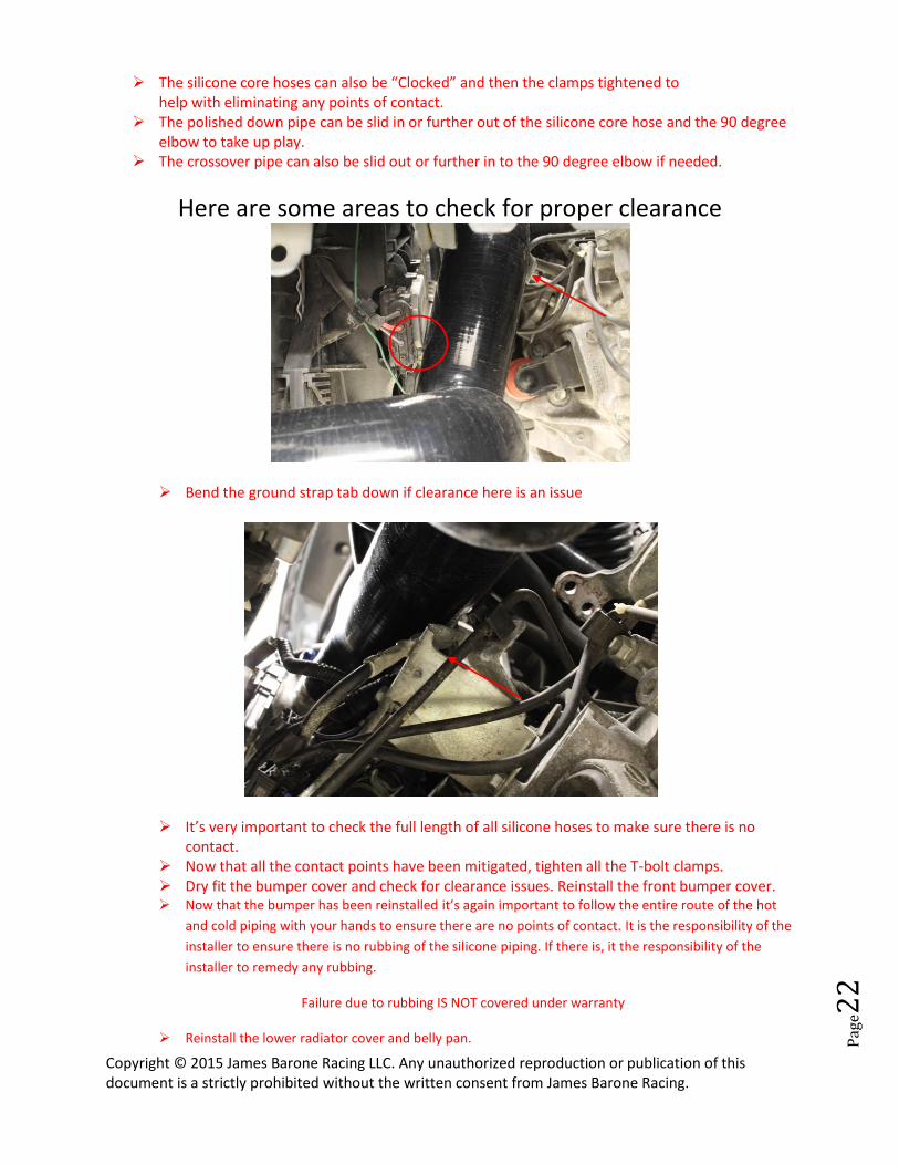
The silicone core hoses can also be “Clocked” and then the clamps tightened to help with eliminating any points of contact.
The polished down pipe can be slid in or further out of the silicone core hose and the 90 degree elbow to take up play.
The crossover pipe can also be slid out or further in to the 90 degree elbow if needed.
Here are some areas to check for proper clearance
Bend the ground strap tab down if clearance here is an issue
It’s very important to check the full length of all silicone hoses to make sure there is no contact.
Now that all the contact points have been mitigated, tighten all the T-bolt clamps. Dry fit the bumper cover and check for clearance issues. Reinstall the front bumper cover. Now that the bumper has been reinstalled it’s again important to follow the entire route of the hot
and cold piping with your hands to ensure there are no points of contact. It is the responsibility of the
installer to ensure there is no rubbing of the silicone piping. If there is, it the responsibility of the
installer to remedy any rubbing.
Failure due to rubbing IS NOT covered under warranty
Reinstall the lower radiator cover and belly pan.
Copyright © 2015 James Barone Racing LLC. Any unauthorized reproduction or publication of this document is a strictly prohibited without the written consent from James Barone Racing.
Pag
e23
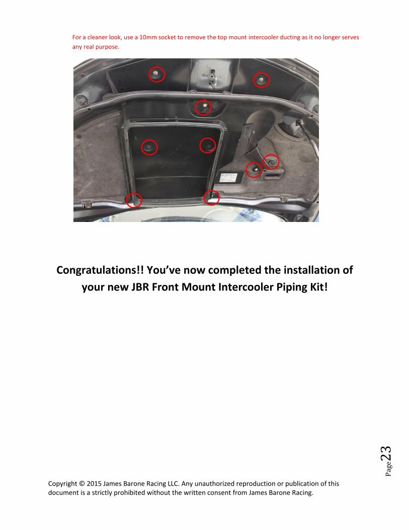
For a cleaner look, use a 10mm socket to remove the top mount intercooler ducting as it no longer serves
any real purpose.
Congratulations!! You’ve now completed the installation of
your new JBR Front Mount Intercooler Piping Kit!
Copyright © 2015 James Barone Racing LLC. Any unauthorized reproduction or publication of this document is a strictly prohibited without the written consent from James Barone Racing.
Pag
e24
SHIPPING All orders are carefully inspected and packaged prior to shipment. The recipient must inspect all shipments for
damage and report any damage to the carrier and JAMES BARONE RACING immediately. JAMES BARONE RACING is
not responsible for damage that occurs during shipping.
RETURNS: All sales are final. JAMES BARONE RACING will only except returns in the event of a manufacturer’s defect.
Defective items will be exchanged for the identical item or repaired at our discretion. Return shipping costs are the
responsibility of the purchaser. An RMA # (Return to Manufacturer Authorization Number) must accompany all
returns. In rare cases when a return is accepted, a 20% restocking fee will be deducted from the refund or credit.
Shipping charges are non- refundable. No returns or exchanges will be accepted after 30 days.
DISCLAIMERS: Failure to carefully follow the installation instructions for your JAMES BARONE RACING product could result in
significant property damage, personal injury, injury to others or even death. Please take the time to read and
thoroughly understand the instructions prior to installation. The instructions are as accurate as possible and may
vary slightly from model year to model year. Professional installation is recommended.
Neither JAMES BARONE RACING nor any of its employees, officers, directors, or shareholders will accept
responsibility for improper use or installation of our products. JAMES BARONE RACING is not responsible for the
misuse, incorrect installation, or failure of any product we sell. Under no circumstances, including but not limited
to negligence, will JAMES BARONE RACING be liable for special or consequential damages that result from the use
or inability to use our products. JAMES BARONE RACING does not assume responsibility for any damage to the
user, driver, passenger or vehicle resulting from the operation of a JAMES BARONE RACING product. PLEASE DRIVE
RESPONSIBLY.
WARRANTY: All JAMES BARONE RACING products carry a lifetime warranty to the original purchaser. Warranty is non-
transferable. Supporting components, manufactured by companies other than James Barone Racing, carry the
manufacturer’s warranty. Warranty does not cover damage to coatings caused by exposure to the elements.
Warranty does not cover damage or failure caused by abuse, misuse, faulty installation or repairs not conducted
by JAMES BARONE RACING. JAMES BARONE RACING is not liable for consequential damages arising from the use of
our products or any indirect damages resulting in the loss of property, revenue or costs for towing, removal,
installation, or re-installation. To receive warranty service you must contact JAMES BARONE RACING to receive an
RMA # (Return to Manufacturer Authorization Number) at which time you will be provided with instructions for
returning the faulty product
CONTACT: If you have questions or problems, e-mail us at [email protected]. Posting questions or problems in
the forums or other social media outlets will only delay you from getting the correct answer or personalized
attention from us.


