

MODEL 3060 EARTH AUGER
PARTS LIST MANUAL
J&M MODEL 3060
EARTH AUGER
WITH MODEL 310POWER UNIT
OM-3060-310-0701

MODEL 3060 EARTH AUGER

MODEL 3060 EARTH AUGER
PREFACE This manual was prepared to acquaint the owner, operator and service man with the construction and servicing of the J&M Model 3060 Earth Auger. We strongly suggest that this manual be studied carefully and understood by all personnel involved in operating or performing maintenance work on the auger. J&M equipment is engineered to provide reliable operation and a long service life under normal operating conditions. Equipment reliability and service life can be improved by following the maintenance procedures in this manual.

MODEL 3060 EARTH AUGER

MODEL 3060 EARTH AUGER
WARRANTY
J&M EQUIPMENT STANDARD WARRANTY J&M warrants new products sold by it to be free from defects in material or workmanship for a period of 1 year after date of delivery to the first user and subject to the following conditions: J&M’s obligation and liability under this WARRANTY is expressly limited to repairing or replacing, at J&M’s option, any parts which appear to J&M, upon inspection, to have been defective in material or workmanship. Such parts shall be provided at no cost to the user, at the business establishment of J&M or the authorized J&M distributor of the product, during regular working hours. This WARRANTY shall not apply to component parts or accessories of products not manufactured by J&M and which may carry the warranty of the manufacturer thereof, or to normal maintenance (such as engine tune-up) or to normal maintenance parts (such as oil filters). Replacement or repair parts installed in the product covered by this WARRANTY are warranted only for the remainder of the warranty, as if such parts were original components of said product. J&M MAKES NO OTHER WARRANTY, EXPRESS OR IMPLIED, AND MAKES NO WARRANTY OF MERCHANTABILITY OR FITNESS, FOR ANY PARTICULAR PURPOSE. J&M’s obligation under this WARRANTY shall not include any transportation charges, cost of installation, duty, taxes or any other charges whatsoever, or any liability for direct, indirect, incidental, or consequential damage of delay. If requested by J&M, products or parts for which a warranty claim is made are to be returned, transportation prepaid to J&M. Any improper use, including operation after discovery of defective of worn parts, operation beyond rated capacity, substitution of parts not approved by J&M or any alteration or repair by others in such manner as in J&M’s judgment affects the product materially and adversely, shall void this WARRANTY. NO EMPLOYEE OR REPRESENTATIVE IS AUTHORIZED TO CHANGE THIS WARRANTY IN ANY WAY OR GRANT ANY OTHER WARRANTY UNLESS SUCH CHANGE IS MADE IN WRITING AND SIGNED BY AN OFFICER OF J&M.

MODEL 3060 EARTH AUGER
1. Read the manual thoroughly before operating or working on the equipment. 2. Read and follow any safety instructions in the CATERPILLAR engine operators
manual. 3. Only well trained and experienced personnel should attempt to operate or maintain
this equipment. 4. Never adjust, lubricate or repair the unit when it is in operation, or lifted above
ground level. 5. Never remove, paint over or cover warning or safety labels. If labels become
damaged or unreadable, replace immediately. 6. All personnel should wear approved safety clothing, including HARD HATS,
SAFETY SHOES, SAFETY GLASSES and HEARING PROTECTION when in the vicinity of this machinery.
7. Do not stand any closer to this equipment than necessary when it is in operation. Parts may loosen and fall. Dirt and rocks may fall from flighting. Parts may loosen and fall. Never stand under operating, or elevated, equipment.
8. When maintaining or repairing the equipment, never substitute parts not supplied, or approved in writing, by J&M.
9. Do not weld, or flame cut, on this equipment. 10. Never use or store flammable liquids on or near the engine. 11. Insure that all lifting equipment, including cranes, wire rope, slings, hooks, shackles,
etc., are properly sized for the worst case loads anticipated during operations. 12. If there are any questions about the weights, specifications, or performance of the
unit, contact J&M before handling or operating the equipment. 13. If the equipment is to be used for anything other than drilling plumb holes, contact
J&M before using the unit. 14. Check wire rope clips for tightness, and check wire ropes for wear, daily. 15. Insure that ground vibrations will not damage or collapse adjacent structures or
excavations. 16. Remove all tools, parts and electrical cords before starting the unit. 17. When operating in an enclosed area, pipe exhaust fumes outside. Continued
breathing of exhaust fumes may be fatal. 18. When servicing batteries, do not smoke or use open flames in the vicinity. Batteries
generate explosive gas during charging. There must be proper ventilation when charging batteries.
19. When filling fuel tank, do not smoke or use open flame in the vicinity. 20. If abnormal equipment operation is observed, discontinue use immediately and
correct the problem. Do not leave the equipment control pendant (radio control) unattended.
21. Store oily rags in approved containers, and away from engine exhaust system. 22. Make sure that the auger rotation switch is in NEUTRAL before starting the power
unit engine. 23. Do not adjust, or set, hydraulic pressures higher or lower than those specified in the
manual. 24. Never operate this equipment with hydraulic hoses that are damaged or “kinked”.
Replace damaged hoses immediately. 25. Do not lift, or support, hydraulic hoses with wire rope slings. 26. Never attempt to connect quick disconnects when the power unit is running. 27. Do not pull on, or attempt to move equipment, with hydraulic hoses.
SAFETY INSTRUCTIONS

MODEL 3060 EARTH AUGER
28. Do not attempt to locate hydraulic leaks with your hands. High pressure hydraulic leaks can penetrate the skin, causing severe damage, blood poisoning and infection. Do not attempt to repair leaks while the equipment is in operation.
29. Do not attempt to tighten, or loosen, fittings or hoses when the machine is in operation.
30. Power unit must always be placed on level, stable, ground. 31. Do not remove power unit heat shields, or operate power unit without heat shields.
Severe fires may result. 32. A properly maintained fire extinguisher, suitable for oil fires, must be kept in the
immediate vicinity of equipment operations. 33. When moving or transporting this equipment, insure that the vehicle or vessel is of
sufficient capacity to handle the load, and that the equipment is properly tied down. 34. When moving or transporting this equipment, be sure that quick disconnect dust
caps are tight, and that cap safety cables are in place. Be sure that all equipment parts are tight, or properly secured, before shipment. Unsecured parts may vibrate loose and fall, during transport, causing injury or property damage.
35. Keep crane boom, flighting, leads, wire rope and other equipment at least 15’ (5M) from electrical power lines, transformers and other electrical equipment, or at such distance as required by applicable safety codes.
36. Rounded or damaged bolt heads or nuts should be replaced so that proper torque values may be obtained. Proper torque values are necessary to prevent parts on this equipment, leads and crane boom from loosening and falling. Refer to Torque Chart, in the manual, for proper values.
37. Make sure that the crane and leads have sufficient capacity to handle the auger, flighting and dirt expected on the job. High down pull forces can be generated if the flighting screws itself into the ground.
38. Insure that the leads are adequately secured against rotation before starting drilling operations.
39. When extracting flighting from ground, check crane load/radius tables to be sure crane capacity is adequate for maximum allowable extraction pull.
40. When extracting flighting, or any other drilling operations, always be sure that the crane line is aligned with the centerline of the flighting. Do not side load crane boom or auger. Dangerous crane boom, or auger, damage may result.
41. When extracting flighting, do not exceed the rated capacity of the auger. 42. Keep hands away from rotating flighting, auger shaft and rotary joint. 43. Keep hands, feet and tools well clear of flighting guides. 44. API flighting connectors must be secured to prevent unscrewing during reverse
(ccw) rotation. Flighting may fall. 45. Do not allow clothing, hoses, ropes, etc. to become entangled in, or wrap around,
rotating flighting, auger shaft or rotary joint. 46. When drilling angled or horizontal holes, insure that the leads, and crane boom,
have sufficient bending strength to handle the worst case load. Consult J&M.
REMEMBER, SAFETY IS EVERYONE’S BUSINESS.
SAFETY INSTRUCTIONS
MODEL 3060 EARTH AUGER
MODEL 3060 EARTH AUGER
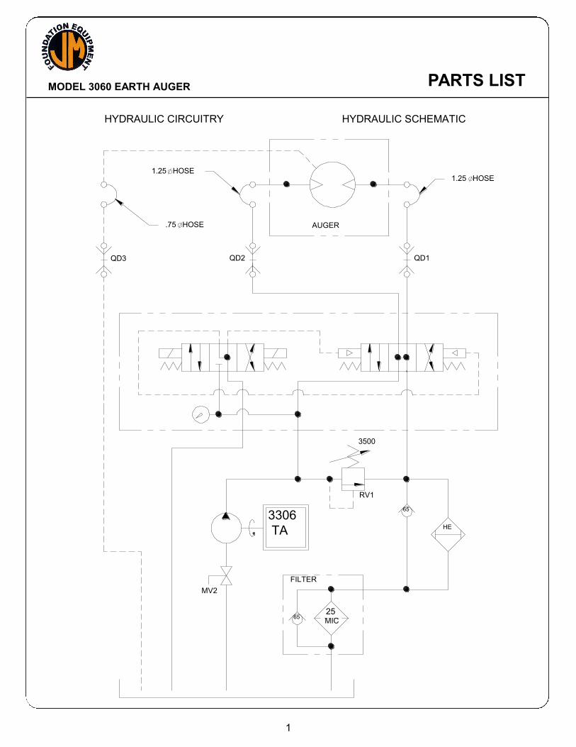
HYDRAULIC CIRCUITRY HYDRAULIC SCHEMATIC
1
3306
TA HE
2565
AUGER
3500
FILTER
QD3
MV2
RV1
MIC
QD2
65
QD1
1.25 HOSE
.75 HOSE
1.25 HOSE
PARTS LIST

MODEL 3060 EARTH AUGER
PARTS LIST

MODEL 3060 EARTH AUGER
ELECTRICAL CIRCUITRY ELECTRICAL SCHEMATIC
2
SCALE:
VIEW
4063 LIBERTY AVENUE PITTSBURGH, PA 15224
& HYDRAULIC SYSTEMS, INC.DWN. BY: DATE: DESCRIPTION
MATERIAL:
REV:
~
FIGE310003 1 OF 1
SEG 2-23-99 310 POWER UNIT ELECTRICAL SCHEMATIC
~
STARTER
M O TO R
TO ENG I NE
BATTERY - 24 VDC - ( 2) 31P
1
14
3
STARTER RELAY
15
2
+- RED
AM M ETER
ALTERNATO R
NEG
O UTPUT
C
RS
B
6
12
3
12
ENG I NE STARTER SW I TCH
M AI N PO W ER
7
ENG I NE
WATER TEM P
S BC
12
10
BLA
CK
RED
10
O I L PRESS
ENG I NE
FUEL SO L
11
SHUTDO WN
10
REV
FO R
6 15SLO W
FAST
1
7
5
4
98
TACH
SENDER13
1
TACHO M ETER
10
1
EM ERG
STO P
ENCLO SED I TEM S I N
CO NTRO L PENDANT
V1B
C
M
4
5
YELLO W
RED
ELECTRI C THRO TTLE
V1A
C
1
REVERSE ( W HI TE)
FO RWARD ( WHI TE)
1
1
8
9
1
B
FU
10 A
FU
BLACK
G REEN
RESET
PARTS LIST

MODEL 3060 EARTH AUGER
GENERAL DATA ABBREVIATIONS
The abbreviations shown below are used throughout the parts lists and various other parts of the manual.
ASM. Assembly BHCS Button Head Cap Screw Cyl. Cylinder DC Direct Current FHCS Flat Head Cap Screw FLCS Flanged Head Cap Screw Gr Grade HC High Collar HHCS Hex Head Cap Screw HHPP Hex Head Pipe Plug HSSS Hex Socket Set Screw Hyd. Hydraulic ID Inside Diameter Lg. Long mm Millimeter Mtg. Mounting NPT. National Pipe Thread OD Outside Diameter PHMS Phillips Head Machine Screw P/N Part Number Qty. Quantity RHMS Round Head Machine Screw Sch. Schedule SHCS Socket Head (Allen) Cap Screw SHPP Socket Head Pipe Plug SHSS Socket Head Shoulder Screw S/N Serial Number Sol. Solenoid UNF Unified National Fine thread UNC Unified National Course thread
3
PARTS LIST

MODEL 3060 EARTH AUGER
VII. GENERAL DATA SCREWS AND BOLTS
1. Practically all connections on the unit are made with socket head (Allen) cap screws. These high-strength screws are available at most industrial supply houses.
2. Screws and bolts are designated in the PARTS LIST in abbreviated form.
(Refer to the previous page, for specific abbreviations). Listed below is a typical screw description: .50 - 13 UNC x 1.50 Lg SHCS
.50 = Diameter 13 UNC = Threads Per Inch 1.50 Lg = Length SHCS = Screw Type Abbreviation
SERIAL NUMBER LOCATIONS
1. The following J&M units are serial numbered separately:
a. Earth Auger b. Power Unit
2. In addition to the serial number plate itself, the serial number is stamped into
each unit in one or more places as follows:
a. Earth Auger stamped twice - once on the gear case cover, once on the gear case near the hose clamp plate.
b. Power unit stamped twice - once on the upper side of the hydraulic oil
reservoir, once on sub-base near the heat exchanger.
4
PARTS LIST
MODEL 3060 EARTH AUGER
ORDERING PARTS
PROCEDURE
1. When ordering parts, be sure to include the model and serial number of the unit or component. Confirm all telephone orders immediately to avoid duplicating shipment.
2. ORIGINAL EQUIPMENT; Where component serial numbers are given, these
apply only to equipment and components originally furnished with the unit. Where equipment has been changed or upgraded these numbers may not be an adequate description.
3. SHIPMENT; Specify shipping address, phone number, billing address and
method of shipment. UPS and air express shipments must have street address for delivery. All shipments will be made freight collect unless instructed otherwise.
4. SHORTAGES; Claims for shortages, damage or errors should be made
immediately upon receipt of parts. No responsibility will be assumed for delay, damage or loss of material while in transit. Broken, damaged or lost material should be refused or a full description made of damage or loss to the carrier agent on the freight or express bill.
5. RETURN OF PARTS; If for any reason you desire to return parts to the factory
or to any distributor from whom these parts were obtained, you must first secure permission to return the parts. Shipping instructions will be given along with this permission. A fifteen percent handling charge must be assessed against the returned shipment unless an error is made by the factory or by the distributor when filling your order.
5
PARTS LIST

MODEL 3060 EARTH AUGER PARTS LIST
VIII. ORDERING PARTS B. FITTING DESCRIPTION KEY
A Fitting Description code is used to describe all fittings in the Parts Identification section of this manual. The key below explains the structure of the code number in detail.
6
SEL ECT OR INDEX
2 - INCH FITTI NG
9 - METRI C FI TTING
CONF IGURAT ION OR
SHAPE OF FITT ING
S - STRAIGHT FITTING
L - 90 Deg. ELBOW
V - 45 Deg. ELBOW
T - TEE
C - CAP
P - PLUG
U - UNION
X - CROSS
FITT
(FOURTH END FITT'G REQ'D. )
FIRST END SIZE
* IN 1/16THS OF AN INCH
(INDEX 2)
IN MI LLIMETERS ( INDEX 9)
SEE GENERAL SPECI FICATION
SHEET FOR SEQUENCE OF ORDER
FIRST END F ITT ING STYL E
SEE FI TTING STYLE SELECTOR
CHART SC-1
SECOND END SIZE
IF APPLICI ABLE - SEE
FIRST END SIZE
SECOND END FITT ING STYL E
IF APPLICABLE - SEE
FI RST END FITTING STYLE
THIRD END SIZE
IF APPLICABLE - SEE
FI RST END SIZE
THIRD END F ITT ING STYL E
FI RST END SIZE
IF APPLICABLE - SEE
* EXCEPTIONS
90 = 10"
92 = 12"
94 = 14"
M AT ERIAL
1 - CARBON STEEL
2 - BRASS
4 - STAINLESS STL
5 - AAR MAL I RON
6 - MALEABLE IRON
8 - FORGED STEEL
SPECIAL NOT AT IONS
0 - NONE
1 - 125 LB.
3 - SCH 40
4 - SCH 80
PRESSURE RAT ING
INST AL L ATION AID OR
ST YL E OF HEAD
0 - NOT APPLI CABLE
H - REGULAR HEX
Q - SQUARE HEAD (EXT.)
R - SQUARE HEAD ( INT. )
S - HEX HEAD ( INT SOCKET)
T - HEX HEAD (EXT. )
L ENGTH CODE
(ELBOWS & NI PPLES)
__L - LONG (ELBOW)
__X - EXTRA LONG (ELBOW)
__C - CLOSE (NIPPLE)
(CROSSES ONLY)
PIPE NI PPLES (LONG) ONLY
IN DEC. INCHES FOR INDEX 2
050 = 5.0 I NCHES
105 = 10.5 INCHES
99 = NON CODE SIZE
98 = 8"
96 = 6"
SEE FI RST END FITTING SIZE OR
END STYLE
IN MILLIMETERS FOR I NDEX 9
120 = 12.0 MILLIMETERS
084 = 8.4 MILLIMETERS
FOURTH END SIZE &
FITT ING STYL E
SCALE:
VIEW
4063 LIBERTY AVENUE PITTSBURGH, PA 15224
& HYDRAULIC SYSTEMS, INC.DWN. BY: DATE: DESCRIPTION
MATERIAL:
REV:
1:2
FIG0011 OF 1
RJ B 1-12-94 MANUALS FITTING DESCRIPTION KEY
2 L 16 M 12 J 00 0 00L 0 0 0 1- -
MODEL 3060 EARTH AUGER
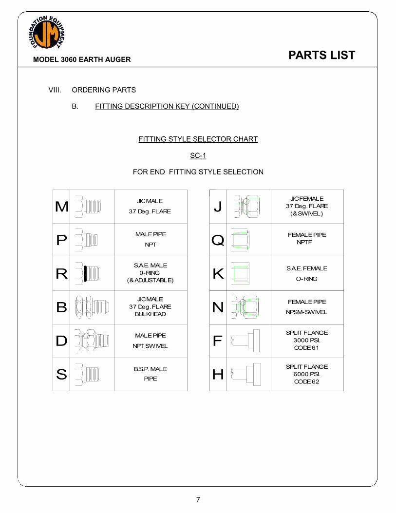
VIII. ORDERING PARTS B. FITTING DESCRIPTION KEY (CONTINUED)
FITTING STYLE SELECTOR CHART
SC-1
FOR END FITTING STYLE SELECTION
7
SCALE:
VIEW
4063 LIBERTY AVENUE PITTSBURGH, PA 15224
& HYDRAULIC SYSTEMS, INC.DWN. BY: DATE: DESCRIPTION
MATERIAL:
REV:
1:1
FIG002 1 OF 1
RJ H 1-12-94 MANUALS FITTING STYLE SELECTOR
Q
D
S
B
B.S.P. MALE
NPT SWIVEL
MALE PIPE
BULKHEAD
37 Deg. FLARE
JIC MALE
PIPE
R
P
M
(& ADJUSTABLE)
0-RING
S.A.E. MALE
MALE PIPE
37 Deg. FLARE
JIC MALE
NPT
SPLIT FLANGE
SPLIT FLANGE
NPSM-SWIVEL
FEMALE PIPE
F
H
N
3000 PSI.
CODE 62
6000 PSI.
CODE 61
S.A.E. FEMALE
FEMALE PIPE
37 Deg. FLARE
K
J
O-RING
NPTF
(& SWIVEL)
JIC FEMALE
PARTS LIST
MODEL 3060 EARTH AUGER
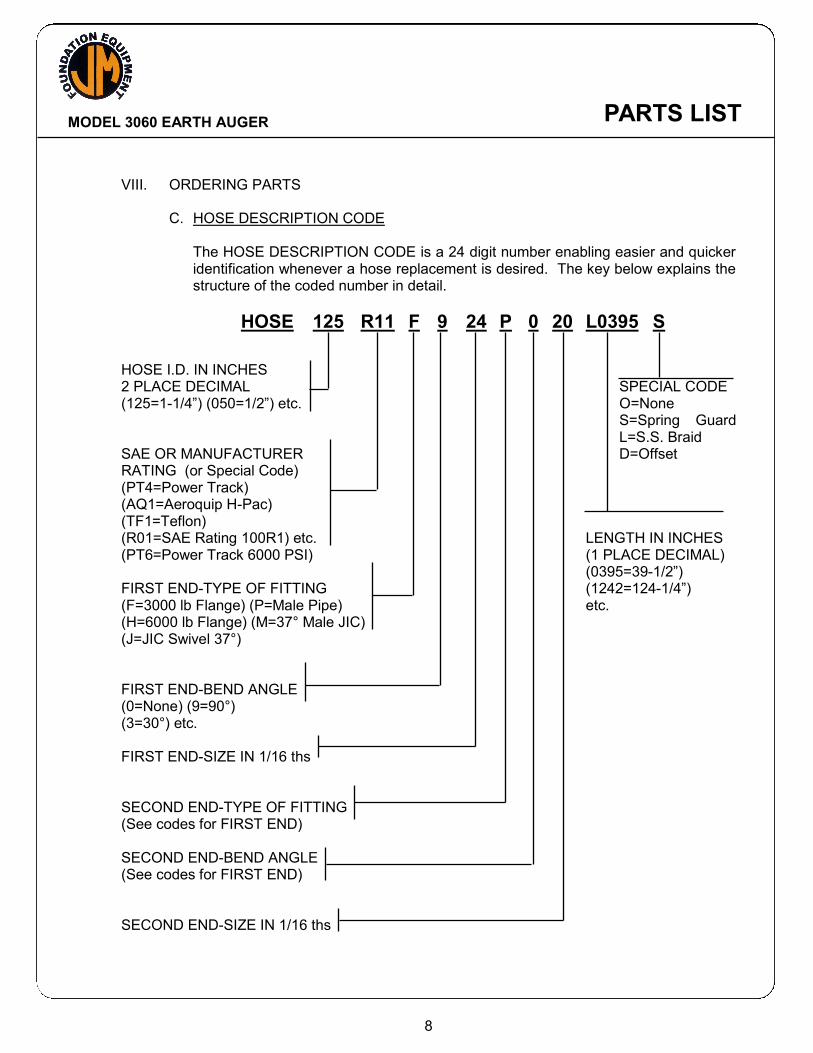
VIII. ORDERING PARTS C. HOSE DESCRIPTION CODE
The HOSE DESCRIPTION CODE is a 24 digit number enabling easier and quicker identification whenever a hose replacement is desired. The key below explains the structure of the coded number in detail.
HOSE 125 R11 F 9 24 P 0 20 L0395 S
HOSE I.D. IN INCHES 2 PLACE DECIMAL SPECIAL CODE (125=1-1/4”) (050=1/2”) etc. O=None S=Spring Guard L=S.S. Braid SAE OR MANUFACTURER D=Offset RATING (or Special Code) (PT4=Power Track) (AQ1=Aeroquip H-Pac) (TF1=Teflon) (R01=SAE Rating 100R1) etc. LENGTH IN INCHES (PT6=Power Track 6000 PSI) (1 PLACE DECIMAL) (0395=39-1/2”) FIRST END-TYPE OF FITTING (1242=124-1/4”) (F=3000 lb Flange) (P=Male Pipe) etc. (H=6000 lb Flange) (M=37° Male JIC) (J=JIC Swivel 37°) FIRST END-BEND ANGLE (0=None) (9=90°) (3=30°) etc. FIRST END-SIZE IN 1/16 ths SECOND END-TYPE OF FITTING (See codes for FIRST END) SECOND END-BEND ANGLE (See codes for FIRST END) SECOND END-SIZE IN 1/16 ths
8
PARTS LIST

MODEL 3060 EARTH AUGER
EARTH AUGER ASM 800357
9
PARTS LIST

MODEL 3060 EARTH AUGER
EARTH AUGER ASM 800357
SECTION A-A
10
PARTS LIST

MODEL 3060 EARTH AUGER
EARTH AUGER ASM 800357 Part Item Number Qty. Description 1 810555 1 Gear Box Pin Asm 2 400997 2 Retainer Ring 3 400948 3 Seal 4 100085 17 .625-11 X 2.25 Lg SHCS 5 100007 29 .625 Lock Washer-Medium 6 400998 1 Output Shaft 7 400946 2 7.5 Ring Feder Clamp 8 400999 1 Drive Flange 9 400944 1 425-O-Ring 10 400942 2 Bearing 11 400940 2 Snap Ring (7.50 Dia) 12 400993 1 Gear 13 400824 1 3060 Auger S/N Plate 14 400936 1 Shim Pack 15 100071 8 .625-11 X 2.5 Lg Shcs Loc-Wel 16 400545 11 .75-10 UNC X 3 Lg SHCS 17 400978 1 Lifting Bale 18 140111 10 .75-10 X 4.0 Lg SHCS 19 100069 21 .75 Lock Washer Medium 20 130135 1 .625-11 X 3.5 Lg SHCS 21 400995 1 Pinion Gear 22 400970 1 Retainer 23 100051 3 .375-16 X 1.0 Lg Shcs Loc-Wel 24 400149 5 .375 Lock Washer 25 400934 1 Plantatary Drive Adapter 26 400932 1 Drive Motor 27 100614 12 .5-13 UNC X 1.50 Lg HHCS 28 100121 12 .5 Lock Washer Medium 29 100596 4 #24 Split Flange Half 30 110119 2 2-225 O-Ring 31 400714 1 FITT2S-08M04R000-000H001 32 400928 1 HOSE063R01J008P012L05600 33 400227 1 FITT2L-06M06P000-0000001 34 400926 1 HOSE038R01J006J006L02500 35 400203 1 FITT2S-06M06P000-000H001 36 400915 1 Expansion Tank Assembly 37 400919 2 4" U-Clamp 38 400923 2 .375-16 UNC X 7" Lg Allthread 39 100535 2 .375 -16 Hex Nut 40 400151 2 .375 Flat Washer
11
PARTS LIST
MODEL 3060 EARTH AUGER
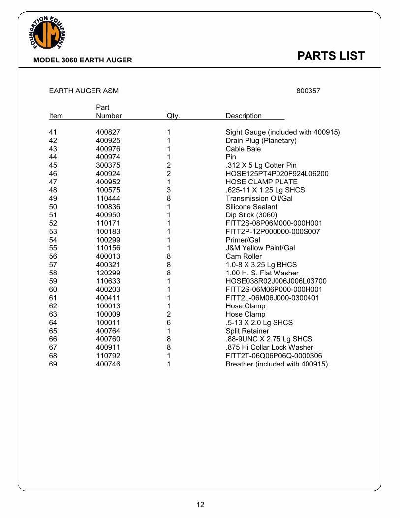
EARTH AUGER ASM 800357 Part Item Number Qty. Description 41 400827 1 Sight Gauge (included with 400915) 42 400925 1 Drain Plug (Planetary) 43 400976 1 Cable Bale 44 400974 1 Pin 45 300375 2 .312 X 5 Lg Cotter Pin 46 400924 2 HOSE125PT4P020F924L06200 47 400952 1 HOSE CLAMP PLATE 48 100575 3 .625-11 X 1.25 Lg SHCS 49 110444 8 Transmission Oil/Gal 50 100836 1 Silicone Sealant 51 400950 1 Dip Stick (3060) 52 110171 1 FITT2S-08P06M000-000H001 53 100183 1 FITT2P-12P000000-000S007 54 100299 1 Primer/Gal 55 110156 1 J&M Yellow Paint/Gal 56 400013 8 Cam Roller 57 400321 8 1.0-8 X 3.25 Lg BHCS 58 120299 8 1.00 H. S. Flat Washer 59 110633 1 HOSE038R02J006J006L03700 60 400203 1 FITT2S-06M06P000-000H001 61 400411 1 FITT2L-06M06J000-0300401 62 100013 1 Hose Clamp 63 100009 2 Hose Clamp 64 100011 6 .5-13 X 2.0 Lg SHCS 65 400764 1 Split Retainer 66 400760 8 .88-9UNC X 2.75 Lg SHCS 67 400911 8 .875 Hi Collar Lock Washer 68 110792 1 FITT2T-06Q06P06Q-0000306 69 400746 1 Breather (included with 400915)
12
PARTS LIST
MODEL 3060 EARTH AUGER
REVERSE
FORWARD
CASE DRAIN
1
121
334
SCALE:
VIEW
4063 LIBERTY AVENUE PITTSBURGH, PA 15224
& HYDRAULIC SYSTEMS, INC.DWN. BY: DATE: DESCRIPTION
MATERIAL:
REV:
1:5
800375 1 OF 1
SEG 2-17-99 MODEL 3060 AUGER INTERCONNECTING HOSES
2 1
89
1011 7
56 7
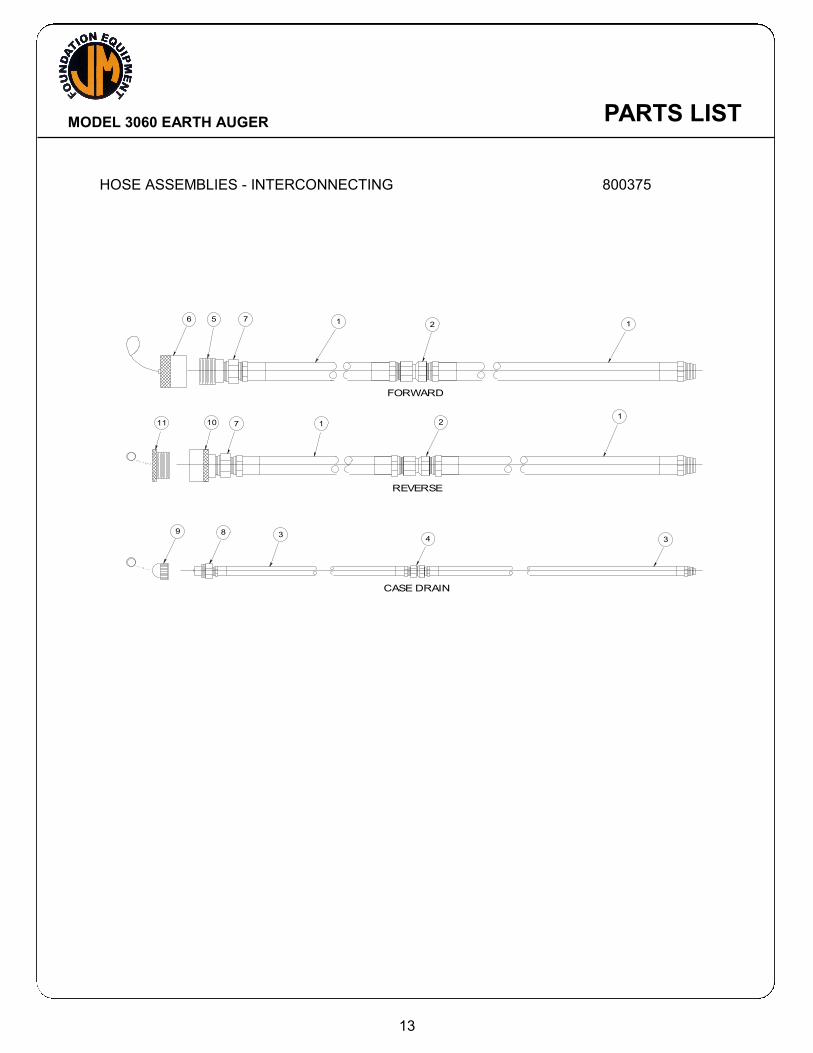
HOSE ASSEMBLIES - INTERCONNECTING 800375
13
PARTS LIST
MODEL 3060 EARTH AUGER
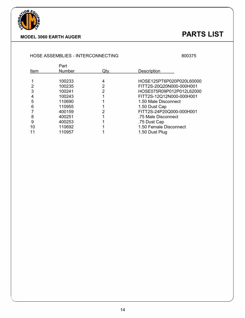
HOSE ASSEMBLIES - INTERCONNECTING 800375 Part Item Number Qty. Description 1 100233 4 HOSE125PT6P020P020L60000 2 100235 2 FITT2S-20Q20N000-000H001 3 100241 2 HOSE075R09P012P012L62000 4 100243 1 FITT2S-12Q12N000-000H001 5 110690 1 1.50 Male Disconnect 6 110955 1 1.50 Dust Cap 7 400159 2 FITT2S-24P20Q000-000H001 8 400251 1 .75 Male Disconnect 9 400253 1 .75 Dust Cap 10 110692 1 1.50 Female Disconnect 11 110957 1 1.50 Dust Plug
14
PARTS LIST

MODEL 3060 EARTH AUGER
CONTROL PENDANT ASSEMBLY 810753
15
SCALE:
VIEW
4063 LIBERTY AVENUE PITTSBURGH, PA 15224
& HYDRAULIC SYSTEMS, INC.DWN. BY: DATE: DESCRIPTION
MATERIAL:
REV:
1:3
FIG810753 1 OF 1
SEG 2-22-99 MODEL 310 POWER UNIT PENDANT ASSEMBLY
~
EM ERGENCY STOP
REV OFF FOR
SLOW FAST
1
32
6 7
54
8 9
PARTS LIST

MODEL 3060 EARTH AUGER
CONTROL PENDANT ASSEMBLY 810753 Part Item Number Qty. Description 1 130153 1 Pendant Enclosure 2 130509 1 Emergency Stop Label 3 130507 1 Emergency Stop Button 4 100864 1 Rev-Off-For Nameplate 5 130155 1 Switch 6 100562 1 Slow-Fast Nameplate 7 100566 1 Switch 8 110603 1 1.0 Strain Relief 9 100560 50 Pendant Cable/Ft
16
PARTS LIST

MODEL 3060 EARTH AUGER
13 116 11 113
110
111 112
78 64
67 68
65
6691
908311
87
7
9 10
811
113
79 81 80 72 66 26 11 71
44
107 106
72
68
87
91
71
TP
TO F IL T ER
TO COOL ERFROM PUM P
DRAIN
SCALE:
VIEW
4063 LIBERTY AVENUE PITTSBURGH, PA 15224
& HYDRAULIC SYSTEMS, INC.DWN. BY: DATE: DESCRIPTION
MATERIAL:
REV:
1:16
FIG800365A 2 OF 2
SEG 2-22-99 MODEL 310 POWER UNIT FINAL ASSEMBLY
79 122121
10 143
127 128
126
60 53
129
69
123
125
41 138 40
73 124
5
48"
138"
FORWARD
REVERSE
1
114
115
117
2
3
4
5
6
15
14
16 63 90109 46 50 4531 118 47
50
48 514210
36
42
61
38
39
40
41
43
35
119
109
37
42
10
32
33
34
56
~
5492
107
555756 62
27
28
29
30
26
52
22
20
18
17
19
21
2324
25
26
12
SCALE:
VIEW
4063 LIBERTY AVENUE PITTSBURGH, PA 15224
& HYDRAULIC SYSTEMS, INC.DWN. BY: DATE: DESCRIPTION
MATERIAL:
REV:
1:16
FIG800365M 1 OF 2
SEG 2-22-99 MODEL 310 POWER UNIT FINAL ASSEMBLY
61
139
140
141
E M E R G E N C Y S T O P
R E V / F O R
S L O W F A S T
10
130
131
59
10
142
9 49
143
138
134 137
136
135
39 133
58
41
132
80"
POWER UNIT ASSEMBLY 800365
17
PARTS LIST
MODEL 3060 EARTH AUGER
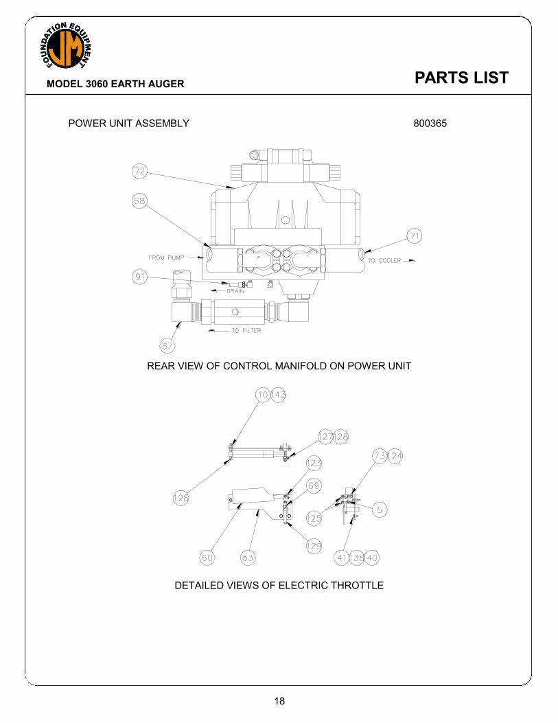
POWER UNIT ASSEMBLY 800365
REAR VIEW OF CONTROL MANIFOLD ON POWER UNIT
DETAILED VIEWS OF ELECTRIC THROTTLE
18
PARTS LIST
MODEL 3060 EARTH AUGER
PARTS LIST

MODEL 3060 EARTH AUGER
POWER UNIT ASSEMBLY 800365 Part Item Number Qty. Description 1 400954 1 Skid Subbase 2 400960 1 Reservoir (331) 3 400958 1 Reservior Cover 4 400956 1 Reservoir Cover Gasket 5 100595 39 .25-20 X 1.25 Lg SHCS 6 100559 38 .25 Lock Washer 7 400085 1 Return Filter Asm. 8 810119 2 K25 Element Assembly 9 100143 6 .375-16 X 1.25 Lg SHCS Loc Wel 10 400149 13 .375 Lock Washer 11 100588 4 FITT2L-24M24P000-0000001 12 400916 1 Sight Gage 13 300563 1 Breather/Filler 14 400914 1 Fuel Tank 15 100423 2 FITT2P-08P000000-000S007 16 100417 1 FITT2C-48Q000000-0000306 17 400117 1 Stop Cock 18 400808 1 FITT2S-40P000000-0900001 19 130119 1 FITT2S-40P000000-0450301 20 400195 1 2.5-90 Deg Flexible Coupling 21 400015 1 2.5 Solid Flange 22 110735 7 .5-13 X 2.5 Lg SHCS 23 400379 1 2-232 O-Ring 90 Duro 24 400904 1 Pump 25 400979 4 .5-20UNF X 1.50 Lg HHCS 26 100121 15 .5 Lock Washer Medium 27 400846 1 Pump Adapter 28 100851 12 .438-14 X 1.25 Lg SHCS 29 100443 12 .437 Lock Washer 30 100445 8 .5-13 X 1.0 Lg SHCS Loc Wel 31 100508 1 3306TA Diesel Engine 32 100085 6 .625-11 X 2.25 Lg SHCS 33 100086 6 .625-11 Esna Nut 34 100007 6 .625 Lock Washer-Medium 35 400099 1 Heat Exchanger 36 400922 1 Top Cooler Bracket 37 400920 1 Bottom Cooler Bracket 38 400900 8 .312-18 UNC X 1.50 Lg HHCS 39 100289 18 .312-18 Hex Nut 40 100293 34 .312 Flat Washer
19
PARTS LIST

MODEL 3060 EARTH AUGER
POWER UNIT ASSEMBLY 800365 Part Item Number Qty. Description 41 100287 20 .312 Lock Washer 42 100051 6 .375-16 X 1.0 Lg Shcs Loc Wel 43 110055 1 FITT2P-20P000000-000S007 44 100726 7 Antifreeze/Gal 45 400898 1 Muffler 46 400896 1 Elbow (5"-90 Deg.) 47 400894 1 Exhaust Outlet Elbow 48 140411 1 5.0 Rain Cap 49 130255 1 Engine Throttle 50 140369 3 5 In. U-Clamp 51 400918 1 Muffler Bracket 52 100027 4 .5 Hi-Collar Lock Washer 53 110254 1 Elec Throttle Bracket 54 400890 2 Battery 55 110653 1 Battery Cable-6 56 100537 2 Battery Cable-24" 57 400888 1 Battery Holddown 58 110371 1 Ammeter 59 100429 1 Throttle Cable Seal 60 110246 1 Electric Actuator (24v) 61 400151 4 .375 Flat Washer 62 400231 3 Hold Down Stud 63 400845 1 Breather 64 100596 2 #24 Split Flange Half 65 110119 1 2-225 O-Ring 66 100119 7 .5-13 X 1.25 Lg SHCS Loc Wel 67 100688 1 Bent Stem Adapter 68 400792 1 HOSE150PT4J024F924L04900 69 810617 1 Modified Throttle Arm 70 100446 1 FITT2L-24P24Q000-0000001 71 400788 1 HOSE150R01J024F924L07700 72 810607 1 331 Manifold Asm. 73 110244 1 Tube .38od .28 Id X .88 Lg 78 120049 1 FITT2S-12P12P000-000H001 79 110037 2 FITT2S-24P24P000-000H001 80 110690 1 1.50 Male Disconnect 81 110955 1 1.50 Dust Cap 83 100436 1 Gage (0-60 PSI.) 87 400790 1 HOSE150R01J024J024L06000 90 100145 1 FITT2L-04M04P000-0000001
20
PARTS LIST
MODEL 3060 EARTH AUGER
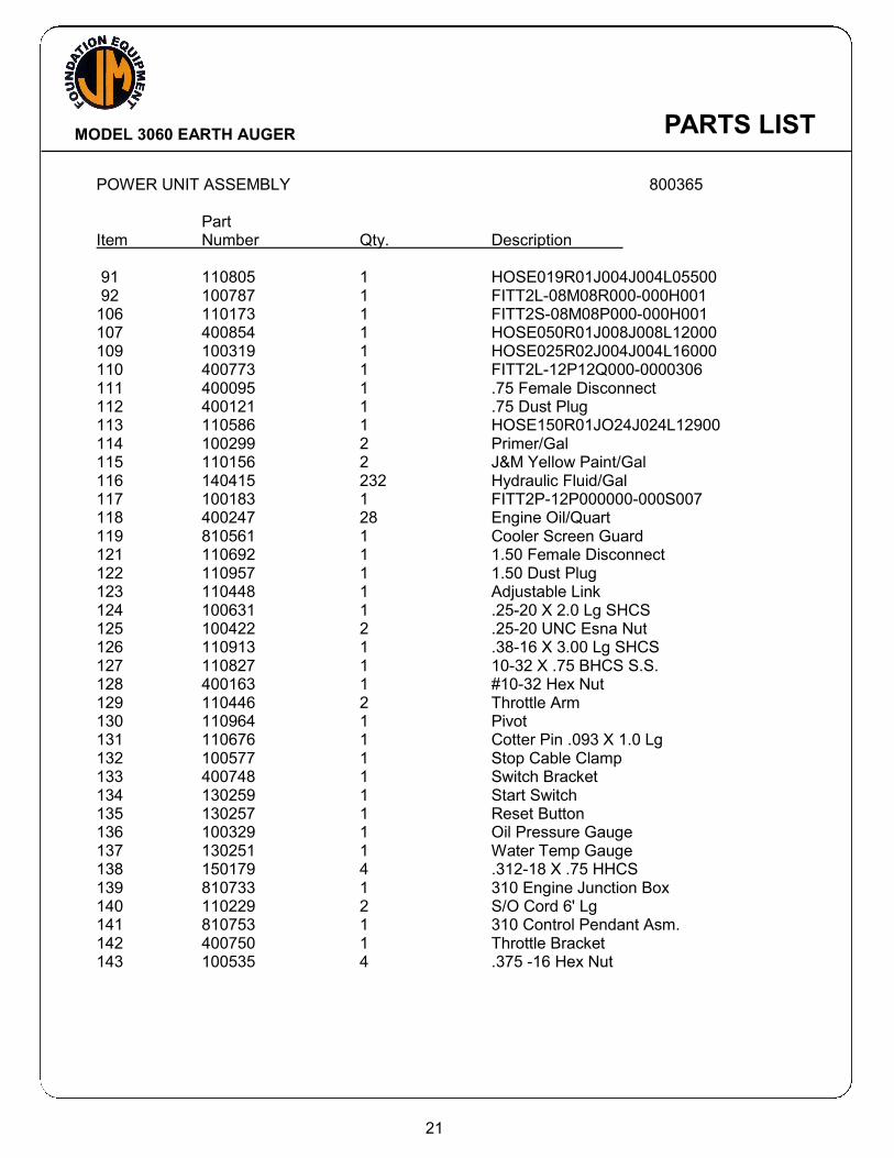
POWER UNIT ASSEMBLY 800365 Part Item Number Qty. Description 91 110805 1 HOSE019R01J004J004L05500 92 100787 1 FITT2L-08M08R000-000H001 106 110173 1 FITT2S-08M08P000-000H001 107 400854 1 HOSE050R01J008J008L12000 109 100319 1 HOSE025R02J004J004L16000 110 400773 1 FITT2L-12P12Q000-0000306 111 400095 1 .75 Female Disconnect 112 400121 1 .75 Dust Plug 113 110586 1 HOSE150R01JO24J024L12900 114 100299 2 Primer/Gal 115 110156 2 J&M Yellow Paint/Gal 116 140415 232 Hydraulic Fluid/Gal 117 100183 1 FITT2P-12P000000-000S007 118 400247 28 Engine Oil/Quart 119 810561 1 Cooler Screen Guard 121 110692 1 1.50 Female Disconnect 122 110957 1 1.50 Dust Plug 123 110448 1 Adjustable Link 124 100631 1 .25-20 X 2.0 Lg SHCS 125 100422 2 .25-20 UNC Esna Nut 126 110913 1 .38-16 X 3.00 Lg SHCS 127 110827 1 10-32 X .75 BHCS S.S. 128 400163 1 #10-32 Hex Nut 129 110446 2 Throttle Arm 130 110964 1 Pivot 131 110676 1 Cotter Pin .093 X 1.0 Lg 132 100577 1 Stop Cable Clamp 133 400748 1 Switch Bracket 134 130259 1 Start Switch 135 130257 1 Reset Button 136 100329 1 Oil Pressure Gauge 137 130251 1 Water Temp Gauge 138 150179 4 .312-18 X .75 HHCS 139 810733 1 310 Engine Junction Box 140 110229 2 S/O Cord 6' Lg 141 810753 1 310 Control Pendant Asm. 142 400750 1 Throttle Bracket 143 100535 4 .375 -16 Hex Nut
21
PARTS LIST

MODEL 3060 EARTH AUGER
CONTROL MANIFOLD ASSEMBLY 810607
23
PARTS LIST
TO COOLER
TO FILTER
FROM PUMP
DRAIN
3 4
7
5 5
8
10
2
16
11
141312 12 13 14
15 916 17 18 13
20
19
21
22

MODEL 3060 EARTH AUGER
CONTROL MANIFOLD ASSEMBLY 810607 Part Item Number Qty. Description 1 130501 1 175B Control Manifold 2 400786 1 4-Way Valve - 24V 3 400039 6 .75-10UNC X 2.75 Lg SHCS 4 100069 6 .75 Lock Washer Medium 5 100853 2 90 Deg S/O Comp Fitting 6 130503 1 Relief Cartridge 7 110055 1 FITT2P-20P000000-000S007 8 110600 1 0-6000 PSI Gage 9 100145 1 FITT2L-04M04P000-0000001 10 100838 1 FITT2L-02P04Q000-00L0001 11 100845 1 FITT2P-04P000000-000S007 12 100596 4 #24 Split Flange Half 13 110119 3 2-225 O-Ring 14 100119 8 .50-13 X 1.25 Lg SHCS Loc Wel 15 100588 1 FITT2L-24M24P000-0000001 16 130339 1 1.5 Check Valve 17 110037 1 FITT2S-24P24P000-000H001 18 100446 1 FITT2L-24P24Q000-0000001 19 100027 4 .50 Hi-Collar Lock Washer 20 110057 1 1.05 Solid Flange 21 100011 4 .50-13 X 2.0 Lg SHCS 22 110618 1 “Solenoid only” for Item 2
24
PARTS LIST

MODEL 3060 EARTH AUGER
1
5 103
4
9 11 12
14
SCALE:
VIEW
4063 LIBERTY AVENUE PITTSBURGH, PA 15224
& HYDRAULIC SYSTEMS, INC.DWN. BY: DATE: DESCRIPTION
MATERIAL:
REV:
1:1.5
FIG810733 1 OF 1
SEG 2-23-99 MODEL 310 POWER UNIT ENGINE JUNCTION BOX
~
2
6
8
7
13
ENGINE JUNCTION BOX 810733
25
PARTS LIST

MODEL 3060 EARTH AUGER
ENGINE JUNCTION BOX 810733 Part Item Number Qty. Description 1 110699 1 Junction Box-Jic 2 400161 2 #10 Lock Washer 3 400163 2 #10-32 Hex Nut 4 110567 6 Terminal Block 5 110569 5 Terminal Mtg. Channel/In 6 100855 3 Straight S/O Comp Fitt 7 110843 3 .5 Locknut 8 110841 3 .5 Plastic Bushing 9 100371 1 Strain Relief 10 110649 2 #10-32 X .375 Lg PHMS 11 130409 1 .75 Lock Nut 12 130411 1 .75 Plastic Bushing 13 400834 1 In-Line Fuse Holder 14 400832 1 10 Amp Fuse
26
PARTS LIST

MODEL 3060 EARTH AUGER
3” ROTARY JOINT ASSEMBLY 800363
27
PARTS LIST
SCALE:
VIEW
4063 LIBERTY AVENUE PITTSBURGH, PA 15224
& HYDRAULIC SYSTEMS, INC.DWN. BY: DATE: DESCRIPTION
MATERIAL:
REV:
1:4
FIG800363 1 OF 1
SEG 2-24-99 MODEL: 3060 AUGER 3" AUGER ROTARY JOINT
~
3
12
14
2
13
5
5
2
1
4
6
7
10
11
9
11
8

MODEL 3060 EARTH AUGER
3” ROTARY JOINT ASSEMBLY 800363 Part Item Number Qty. Description 1 400982 1 3" Swivel Adapter 2 400477 2 3" Victaulic Coupling 3 810551 1 3" Swivel Joint Asm.(J&M) 4 400972 1 Grout Pipe 5 400881 2 3" 75 Coupling 6 100051 6 .375-16 X 1.0 Lg SHCS Loc Wel 7 400149 6 .375 Lock Washer 8 400944 1 425-O-Ring 9 140111 2 .75-10 X 4.0 Lg SHCS Loc Wel 10 400069 1 .75-10 x 2.0 Lg SHCS 11 100069 3 .75 Lock Washer Medium 12 400877 1 3-90 Elbow 13 400879 1 3-45 Elbow 14 100229 1 Grease Fitting
28
PARTS LIST

MODEL 3060 EARTH AUGER
PARTS LIST

MODEL 3060 EARTH AUGER
RECOMMENDED TIGHTENING TORQUE Nominal Nominal Tightening Nominal Nominal Tightening Screw Socket Torque Screw Socket Torque Size Size Ft-Lbs. (Kg-M) Size Size Ft-Lbs. (Kg-M) #10-24 5/32 6 Ft-Lbs. (.83 Kg-M) #10-32 5/32 6 Ft-Lbs. (.83 Kg-M) 1/4-20 3/16 13 Ft-Lbs. (1.8 Kg-M) 1/4-28 3/16 15 Ft-Lbs. (2.1 Kg-M) 5/16-18 1/4 27 Ft-Lbs. (3.7 Kg-M) 5/16-24 1/4 30 Ft-Lbs. (4.2 Kg-M) 3/8-16 5/16 48 Ft-Lbs. (6.6 Kg-M) 3/8-24 5/16 55 Ft-Lbs. (7.6 Kg-M) 7/16-14 3/8 77 Ft-Lbs. (10.6 Kg-M) 7/16-20 3/8 86 Ft-Lbs. (11.9 Kg-M) 1/2-13 3/8 119 Ft-Lbs. (16.4 Kg-M) 1/2-20 3/8 133 Ft-Lbs. (18.4 Kg-M) 5/8-11 1/2 234 Ft-Lbs. (32.3 Kg-M) 5/8-18 1/2 267 Ft-Lbs. (36.9 Kg-M) 3/4-10 5/8 417 Ft-Lbs. (57.6 Kg-M) 3/4-16 5/8 467 Ft-Lbs. (64.5 Kg-M) 7/8-9 3/4 676 Ft-Lbs. (93.4 Kg-M) 7/8-14 3/4 742 Ft-Lbs. (102.5 Kg-M) 1-8 3/4 1,009 Ft-Lbs. (139.4 Kg-M) 1-12 3/4 1,126 Ft-Lbs. (155.6 Kg-M) 1-1/4-7 7/8 1,600 Ft-Lbs. (221.1 Kg-M) 1-1/4-12 7/8 1,800 Ft-Lbs. (248.8 Kg-M) 1-1/2-6 1 2,800 Ft-Lbs. (387 Kg-M) 1-1/2-12 1 3,000 Ft-Lbs. (414.6 Kg-M)
NOTE: These values are for Socket head cap screws only. Button heads, Flat heads and Set screws have different values. Check the Allen Hand Book for correct torque specifications.
29
PARTS LIST

MODEL 3060 EARTH AUGER PARTS LIST


