
7/31/2019 JPEG2000- Wavelet Based Image Compression
http://slidepdf.com/reader/full/jpeg2000-wavelet-based-image-compression 1/14
EE678 WAVELETS APPLICATION ASSIGNMENT 1 1
Group Members:
Ram Singh [email protected] 04307415
Ramesh Verma [email protected] 04307414
Sushil Kumar [email protected] 04307406
Abstract
The need for high-performance image compression is becoming greater and greater as digital
imagery finds its way into many areas of everyday life. JPEG2000 is the state-of -the-art
compression standard emerges from the Joint Photographic Experts Group (JPEG) working
under the auspices of the International Standards Organization. The new standard out performsthe older JPEG standard by approximately 2 dB of peak signal -to- noise ratio (PSNR) for several
images across all compression ratios. Two primary reasons for JPEG2000 s superior
performance are the wavelet transform and embedded block coding with optimal truncation
(EBCOT). JPEG2000 provides a whole new way of interacting with compressed imagery in a
scalable and interoperable fashion. This paper provides a brief review of the new standard,
explaining the technology on which it is based and drawing comparisons with JPEG standards.
Index Terms
JPEG, JPEG2000, Discrete Wavelet Transform (DWT), image compression, sub-band coding, image
coding, Block -code, MRA, color image coding, ROI coding.
I. INTRODUCTION
JPEG2000 is the latest image compression standard to emerge from the body popularly known as the
Joint Photographic Experts Group (JPEG). More formally, this body is denoted ISO/IEC
JTC1/SC29/WG1, which stands for Working Group 1 of Study Committee 29 of Joint Technical
Committee 1 of ISO/IEC. Here, ISO is the International Organization for Standardization, IEC is the
International Electrotechnical Commission, and the word Joint refers to the fact that the standard is
developed and published jointly with the International Telecommunication Union (ITU) [1].
This new standard has been developed to meet the demand for efficient, flexible, and interactive image
representations. JPEG2000 is much more than a compression algorithm, opening up new paradigms for
interacting with digital imagery. At the same time, the features offered by JPEG2000 derive from asingle algorithm rather than a family of different algorithms. In particular, an important goal of
JPEG2000.
This document contains the following sections. In Section II, a brief review of wavelet transforms and
in more detail the properties and construction of regular bi-orthogonal wavelet bases is presented. Then,
section III takes up to JPEG-2000 image compression. JPEG2000 offers numerous advantages over its
predecessor JPEG, their comparison is done in section V.
JPEG2000: Wavelet Based Image Compression
7/31/2019 JPEG2000- Wavelet Based Image Compression
http://slidepdf.com/reader/full/jpeg2000-wavelet-based-image-compression 2/14
EE678 WAVELETS APPLICATION ASSIGNMENT 1 2
II. BACKGROUND THEORY
A. Wavelets and CWT
Wavelets are functions generated from a single function by dilations and translations [3]
)()(
2 / 1,
a
bt
at
ba
(1)
(Here we refer t as a one dimensional variable). The mother wavelet (t) has to satisfy 0)( dx x ,
which implies at least some oscillations ( Technically the wavelet must satisfy the admissibility
condition which is d
2
)() where )( is the Fourier transform of (t). The high
frequency wavelets correspond to a < 1 or narrow width, while low frequency wavelets have a > 1 or
wider width. The basic idea is to represent any arbitrary function f as a superposition of wavelets. Any
such superposition further decomposes f into different scale levels, where each level is then further
decomposed with a resolution adapted to the level.
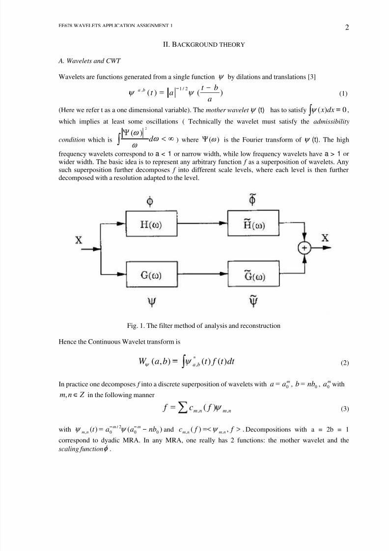
Fig. 1. The filter method of analysis and reconstruction
Hence the Continuous Wavelet transform is
dt t f t baW ba )()(),(*
, (2)
In practice one decomposes f into a discrete superposition of wavelets with
m
aa 0 , 0nbb ,
m
a0 with Z nm, in the following manner
nmnm f c f ,, )( (3)
with )()( 00
2 /
0, nbaat mm
nm and .,)( ., f f c nmnm Decompositions with a = 2b = 1
correspond to dyadic MRA. In any MRA, one really has 2 functions: the mother wavelet and the
scaling function .

7/31/2019 JPEG2000- Wavelet Based Image Compression
http://slidepdf.com/reader/full/jpeg2000-wavelet-based-image-compression 3/14
EE678 WAVELETS APPLICATION ASSIGNMENT 1 3
One also introduces dilated and translated versions of the scaling function
)(2)( 00
2 /
, nba x mm
nm . For a fixed m the )(, xnm are orthonormal and their span is Vm
describe the successive approximation spaces Vm+1 Vm Vm-1 · · ·. Likewise for each
m, the nm, form the basis for the complement of Vm in Vm 1. All of this is translated into the
following algorithm for the computation of )(, f c nm .
)()( ,12, f ag f ck
k mk nnm (4)
)()( ,12, f ah f ck
k mk nnm (5)
where 1)1( l
l
l hg and dx xn xhn )2()(2 . In fact )(, f a nm are coefficients
characterizing the projection of f onto Vm. If f is given in the sampled form, then one can take these
samples for the highest order resolution coefficients na ,0 and (4) describes a sub-band coding algorithm
on these sampled values, with the low pass filter h and the high pass filter g. Since we are using
orthonormal wavelets, these give the exact reconstruction, i.e.
)]()([)( ,2,2,1 f cg f ah f a nmlnnm
n
lnlm (6)
Note that in the Fig.1 H and G correspond to the Fourier transform of h and g respectively. The
problem of analysis and reconstruction essentially boils down to the synthesis of the filters g and h sothat MRA can be done.
B. Applications of Wavelets to image analysis
1) Bi-orthogonal Wavelet bases: Since the images are typically smooth, it seems appropriate that an
reconstruction subband coding scheme for image analysis should correspond to an orthonormal basis
with a reasonably smooth mother wavelet. Plus, for fast computation we need reasonably short FIRfilters. These filters must also possess the property of linear phase, because then we can cascade the
filters without phase compensation to achieve further resolution. Unfortunately there are no non-trivial
orthonormal linear phase FIR filters with the exact reconstruction property except those corresponding
to the Haar bases. To overcome this we use bi-orthogonal basis, in such a scheme the decomposition
method remains the same as in but the new reconstruction equation is :
)](~)(~
[)( ,2,2,1 f cg f ah f anmlnnm
n
lnlm (7)
where the filters h~
and g~ are different from h,g. In order to have exact reconstruction, we impose:
1)1(~n
n
n hg (8)
1
~)1( n
n
n hg (9)
0,2
~k
n
k nhh (10)
This condition can also be written in the following form for symmetric FIR filters:

7/31/2019 JPEG2000- Wavelet Based Image Compression
http://slidepdf.com/reader/full/jpeg2000-wavelet-based-image-compression 4/14
EE678 WAVELETS APPLICATION ASSIGNMENT 1 4
1)(~
)()(~
)( H H H H (11)
Many examples of these filters are possible. We discuss some of these next
2) Different wavelets used in image coding:
1) Spline Filters: These are of having )2 / exp()2 / cos()(~~
jk H K where 0k if k ~ is
even and 1k if k ~
is odd. Hence we have that :
pl
p
K l
p
pl jk H
21
0
~2
)2 / sin(1
2 / exp)2 / cos()(~
(12)
2) The filters used in JPEG2000: Daubechies 9/7 and LeGall 5/3 The LeGall 5/3 and Daubechies 9/7
filters have risen to special prominence because they were selected for inclusion in the JPEG2000
standard. The standard restricts Daubechies 9/7 for lossy compression, and the 5/3 LeGall wavelet,
which has rational coefficients, for reversible or lossless compression. It also specifies that these should
be implemented using the lifting scheme. Because of the minimum support requirement, both waveletscan be obtained by factorizing a maximally flat Daubechies or Dubuc-Deslaurier half-band filter. The
5/3 LeGall is the shortest symmetrical bi-orthogonal wavelet with two regularity factors; its synthesis
scaling function is a linear B-spline. The 9/7 is a variant of Cohen-Daubechies-Feauveaus bi-orthogonal
cubic B-spline construction (shortest scaling of order four) with residual factors that have been divided
up on both sides in a way that makes the basis functions more nearly orthogonal. Also note that the
order in which the filters are applied (analysis versus synthesis) is important: it is such that the shortest
and most regular basis functions are placed on the synthesis side; this is consistent with the principle of
maximizing the approximation power of the representation.
III. JPEG2000 IMAGE COMPRESSION
The JPEG 2000 compression engine (encoder and decoder) is illustrated in block diagram form inFig.2.
Fig. 2. Block Diagram of the JPEG2000 Encoder and Decoder
At the encoder, the discrete transform is first applied on the source image data. The transform
coefficients are then quantized and entropy coded before forming the output code stream (bit stream).
The decoder is the reverse of the encoder. The code stream is first entropy decoded, de-quantized, and
inverse discrete transformed, thus resulting in the reconstructed image data. Although this general block
7/31/2019 JPEG2000- Wavelet Based Image Compression
http://slidepdf.com/reader/full/jpeg2000-wavelet-based-image-compression 5/14
EE678 WAVELETS APPLICATION ASSIGNMENT 1 5
diagram looks like the one for the conventional JPEG, there are radical differences in all of the
processes of each block of the diagram
For the clarity of presentation we have decomposed the whole compression engine into three parts: the
preprocessing, the core processing, and the bit-stream formation part, although there exist high inter-
relation between them. In the preprocessing part the image tiling, the dc-level shifting and the
component transformations are included. The core processing part consists of the discrete transform, the
quantization and the entropy coding processes. Finally, the concepts of the precincts, code blocks,
layers, and packets are included in the bit-stream formation part.
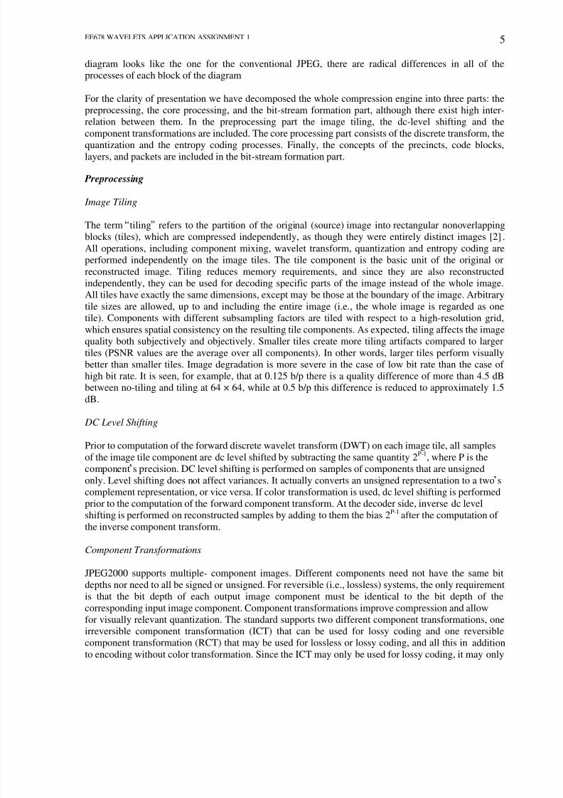
Preprocessing Image Tiling
The term tiling refers to the partition of the original (source) image into rectangular nonoverlapping
blocks (tiles), which are compressed independently, as though they were entirely distinct images [2] .
All operations, including component mixing, wavelet transform, quantization and entropy coding are
performed independently on the image tiles. The tile component is the basic unit of the original or
reconstructed image. Tiling reduces memory requirements, and since they are also reconstructed
independently, they can be used for decoding specific parts of the image instead of the whole image.All tiles have exactly the same dimensions, except may be those at the boundary of the image. Arbitrary
tile sizes are allowed, up to and including the entire image (i.e., the whole image is regarded as one
tile). Components with different subsampling factors are tiled with respect to a high-resolution grid,
which ensures spatial consistency on the resulting tile components. As expected, tiling affects the image
quality both subjectively and objectively. Smaller tiles create more tiling artifacts compared to larger
tiles (PSNR values are the average over all components). In other words, larger tiles perform visually
better than smaller tiles. Image degradation is more severe in the case of low bit rate than the case of
high bit rate. It is seen, for example, that at 0.125 b/p there is a quality difference of more than 4.5 dB
between no-tiling and tiling at 64 × 64, while at 0.5 b/p this difference is reduced to approximately 1.5
dB.
DC Level Shifting
Prior to computation of the forward discrete wavelet transform (DWT) on each image tile, all samples
of the image tile component are dc level shifted by subtracting the same quantity 2P-1
, where P is the
component s precision. DC level shifting is performed on samples of components that are unsigned
only. Level shifting does not affect variances. It actually converts an unsigned representation to a two s
complement representation, or vice versa. If color transformation is used, dc level shifting is performed
prior to the computation of the forward component transform. At the decoder side, inverse dc level
shifting is performed on reconstructed samples by adding to them the bias 2P-1after the computation of
the inverse component transform.
Component Transformations
JPEG2000 supports multiple- component images. Different components need not have the same bit
depths nor need to all be signed or unsigned. For reversible (i.e., lossless) systems, the only requirement
is that the bit depth of each output image component must be identical to the bit depth of the
corresponding input image component. Component transformations improve compression and allow
for visually relevant quantization. The standard supports two different component transformations, one
irreversible component transformation (ICT) that can be used for lossy coding and one reversible
component transformation (RCT) that may be used for lossless or lossy coding, and all this in addition
to encoding without color transformation. Since the ICT may only be used for lossy coding, it may only
7/31/2019 JPEG2000- Wavelet Based Image Compression
http://slidepdf.com/reader/full/jpeg2000-wavelet-based-image-compression 6/14
EE678 WAVELETS APPLICATION ASSIGNMENT 1 6
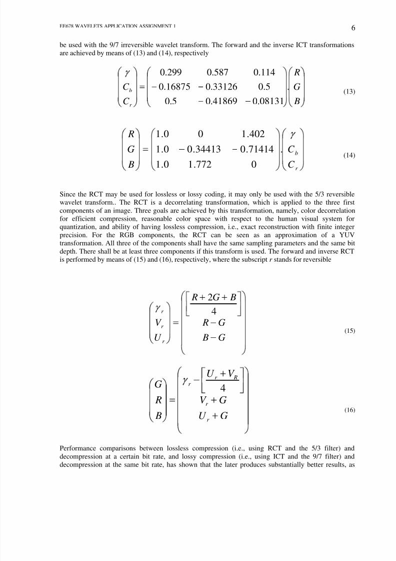
be used with the 9/7 irreversible wavelet transform. The forward and the inverse ICT transformations
are achieved by means of (13) and (14), respectively
B
G
R
C
C
r
b .
08131.041869.05.0
5.033126.016875.0
114.0587.0299.0
(13)
r
b
C
C
B
G
R
.
0772.10.1
71414.034413.00.1
402.100.1
(14)
Since the RCT may be used for lossless or lossy coding, it may only be used with the 5/3 reversiblewavelet transform.. The RCT is a decorrelating transformation, which is applied to the three first
components of an image. Three goals are achieved by this transformation, namely, color decorrelation
for efficient compression, reasonable color space with respect to the human visual system for
quantization, and ability of having lossless compression, i.e., exact reconstruction with finite integer
precision. For the RGB components, the RCT can be seen as an approximation of a YUV
transformation. All three of the components shall have the same sampling parameters and the same bit
depth. There shall be at least three components if this transform is used. The forward and inverse RCT
is performed by means of (15) and (16), respectively, where the subscript r stands for reversible
G B
G R
BG R
U
V
r
r
r 4
2
(15)
GU
GV
V U
B
R
G
r
r
Rr r
4(16)
Performance comparisons between lossless compression (i.e., using RCT and the 5/3 filter) and
decompression at a certain bit rate, and lossy compression (i.e., using ICT and the 9/7 filter) and
decompression at the same bit rate, has shown that the later produces substantially better results, as

7/31/2019 JPEG2000- Wavelet Based Image Compression
http://slidepdf.com/reader/full/jpeg2000-wavelet-based-image-compression 7/14

7/31/2019 JPEG2000- Wavelet Based Image Compression
http://slidepdf.com/reader/full/jpeg2000-wavelet-based-image-compression 8/14
EE678 WAVELETS APPLICATION ASSIGNMENT 1 8
2
)22()2()12()12(
n xn xn xn y ext ext
ext (17)
42)12()12()2()2( n yn yn xn y ext (18)
Figure 3. Three-level dyadic wavelet decomposition of the image Lena.
where xext is the extended input signal and y is the output signal. The 5/3 filter allows repetitive
encoding and de-coding of an image without any loss. Of course, this is true when the decompressed
image values are not clipped when they fall outside the full dynamic range (i.e., 0-255 for an 8 b/p
image). Traditional wavelet transform implementations require the whole image to be buffered and the
filtering operation to be performed in vertical and horizontal directions. While filtering in the horizontal
direction is very simple, filtering in the vertical direction is more cumbersome. Filtering along a row
requires one row to be read; filtering along a column requires the whole image to be read. The line-
based wavelet transform overcomes this difficulty, providing exactly the same transform coefficients asthe traditional wavelet transform implementation. However, the line-based wavelet transform alone
does not provide a complete line-based encoding paradigm for JPEG 2000. A complete row-based
coder has to take also into account all the subsequent coding stages up to the entropy coding.
Table 2. Daubechies 9/7 Analysis and Synthesis Filter Coefficients.
Analysis Filter Coefficients
i Low-Pass Filter hL(i) High-Pass Filter hH(i)
0 0.6029490182363579 1.115087052456994
±1 0.2668641184428723 -0.5912717631142470
±2 -0.07822326652898785 -0.05754352622849957
±3 -0.01686411844287495 0.09127176311424948
±4 0.02674875741080976

7/31/2019 JPEG2000- Wavelet Based Image Compression
http://slidepdf.com/reader/full/jpeg2000-wavelet-based-image-compression 9/14
EE678 WAVELETS APPLICATION ASSIGNMENT 1 9
Synthesis Filter Coefficients
i Low-Pass Filter gL(i) High-Pass Filter gH(i)
0 1.115087052456994 0.6029490182363579
±1 0.5912717631142470 -0.2668641184428723
±2 -0.05754352622849957 -0.07822326652898785
±3 -0.09127176311424948 0.01686411844287495
±4 0.02674875741080976
Table 3. Le Gall 5/3 Analysis and Synthesis Filter Coefficients.
Analysis Filter Coefficients Synthesis Filter Coefficients
iLow-Pass
Filter hL(i)
High-Pass
Filter hH(i)
Low-Pass
Filter gL(i)
High-Pass
Filter gH(i)
0 6/8 1 1 6/8
±1 2/8 -1/2 1/2 -2/8
±2 -1/8 - - -1/8
Quantization
After transformation, all coefficients are quantized. Quantization is the process by which the
coefficients are reduced in precision. This operation is lossy, unless the quantization step is 1 and the
coefficients are integers, as produced by the reversible integer 5/3 wavelet. Each of the transform
coefficients ab (u, v) of the subband b is quantized to the value q b( u, v) according to the formula
b
b
bb
vuavuasignvuq
),()),((),( (19)
The quantization step-size b is represented relative to the dynamic range of subband b. In other words,
the JPEG 2000 standard supports separate quantization step-sizes for each subband. However, one
quantization step-size is allowed per subband. The dynamic range depends on the number of bits used
to represent the original image tile component and on the choice of the wavelet transform. All quantized
transform coefficients are signed values even when the original components are unsigned. These
coefficients are expressed in a sign-magnitude representation prior to coding. For reversible
compression, the quantization step-size is required to be one.

7/31/2019 JPEG2000- Wavelet Based Image Compression
http://slidepdf.com/reader/full/jpeg2000-wavelet-based-image-compression 10/14
EE678 WAVELETS APPLICATION ASSIGNMENT 1 10
Entropy Coding
Entropy coding is achieved by means of an arithmetic coding system that compresses binary symbols
relative to an adaptive probability model associated with each of 18 different coding contexts. The MQ
coding algorithm is used to perform this task and to manage the adaptation of the conditional
probability models. This algorithm has been selected in part for compatibility reasons with the
arithmetic coding engine used by the JBIG2 compression standard and every effort has been made to
ensure commonality between implementations and surrounding intellectual property issues for JBIG2
and JPEG2000. The recursive probability interval subdivision of Elias coding is the basis for the binary
arithmetic coding process. With each binary decision, the current probability interval is subdivided into
two subintervals, and the code stream is modified (if necessary) so that it points to the base (the lower
bound) of the probability subinterval assigned to the symbol, which occurred. Since the coding process
involves addition of binary fractions rather than concatenation of integer code words, the more probable
binary decisions can often be coded at a cost of much less than one bit per decision.
Bit -Stream Formation
Precincts and code blocks
After quantization, each subband is divided into rectangular blocks, i.e., nonoverlapping rectangles.Three spatially consistent rectangles (one from each subband at each resolution level) comprise a packet
partition location or precinct. Each precinct is further divided into nonoverlapping rectangles, called
code blocks, which form the input to the entropy coder. The size of the code block is typically 64x 64
and no less than 32 x 32.
Packets and Layers
For each code block, a separate bit stream is generated. No information from other blocks is utilized
during the generation of the bit stream for a particular block. Rate distortion optimization is used to
allocate truncation points to each code block. The bit stream has the property that it can be truncated to
a variety of discrete lengths, and the distortion incurred, when reconstructing from each of these
truncated subsets, is estimated and denoted by the mean squared error. During the encoding process, thelengths and the distortions are computed and temporarily stored with the compressed bit stream itself.
The compressed bit streams from each code block in a precinct comprise the body of a packet. A
collection of packets, one from each precinct of each resolution level, comprises the layer.A packet
could be interpreted as one quality increment for one resolution level at one spatial location, since
precincts correspond roughly to spatial locations. Similarly, a layer could be interpreted as one quality
increment for the entire full resolution
Summary
We now give a summary of the above steps:
The source image is decomposed into components.
The image and it s components are decomposed into tiles. The tile-component is the basic unitof the original or reconstructed image.
The DWT is applied to each tile and decomposition into sub-bands is done. The tile is
decomposed into various resolution levels.
The decomposition levels are made up of sub-bands of coefficients that describe the frequency
characteristics of local areas of the tile component.
The sub-bands of the coefficients are quantized and collected into rectangular arrays of code
blocks .
The bit-planes of the coefficients in a code block are entropy encoded.

7/31/2019 JPEG2000- Wavelet Based Image Compression
http://slidepdf.com/reader/full/jpeg2000-wavelet-based-image-compression 11/14
EE678 WAVELETS APPLICATION ASSIGNMENT 1 11
The encoding is done in such a manner that some ROI are encoded at a higher quality than
others.
Marker are added in the bit-stream to improve error resilience.
The code stream had a major header in the beginning which contains the image information
plus other things.
A meta-data file describing the image is also added.
IV. COMPARISON OF JPEG AND JPEG2000
In this section, we briefly discuss the relative merits of JPEG and JPEG2000 . JPEG2000 provides an
advantage in compression efficiency over JPEG, its primary advantage lies in its rich feature set. The
JPEG standard specifies four modes: sequential, progressive, hierarchical, and lossless. In the sequential
mode, imagery is compressed and decompressed in a block -based raster fashion from top to bottom. On
the other hand, if the progressive mode of JPEG is employed, lower quality decompressions are
possible and the code-stream is ordered so that the most important bits appear earliest in the code-
stream. Hierarchical JPEG is philosophically similar. However, rather than improving quality,
additional bytes are used to successively improve the resolution (or size) of the decoded imagery.
When the lossless mode of JPEG is employed, only lossless decompression is available. High
compression ratios are generally not possible with lossless compression.
Certain interactions between the modes are allowed according to the JPEG standard. For example,
hierarchical and progressive modes can be mixed within the same code stream. However, few if any
implementations have exploited this ability. Also, quite different technologies are employed for the
lossless and lossy modes. The lossless mode relies on predictive coding techniques, while lossy
compression relies on the discrete cosine transform. A JPEG code-stream must be decoded in the
fashion intended by the compressor. For example, if reduced resolution is desired at the decompressor
(when a progressive mode was employed at the compressor), the entire image must be decompressed
and then downsampled. Conversion of a code-stream from one mode to another can be difficult.
Typically, such conversion must be accomplished via decompression/ recompression, sometimes
resulting in loss of image quality.
JPEG2000 tightly integrates the benefits of all four JPEG modes in a single compression architecture
and a single code stream syntax. The compressor can decide maximum image quality up to and
including lossless. Also chosen by the compressor is the maximum resolution or size. Any image
quality or size can be decompressed from the resulting code-stream, up to and including those selected
at encode time. Many types of progressive transmission are supported by JPEG2000. Progressive
transmission is highly desirable when receiving imagery over slow communication links. As more data
are received, the rendition of the displayed imagery improves in some fashion. JPEG2000 supports
progression in four dimensions: quality, resolution, spatial location, and component. The first
dimension of progressivity in JPEG2000 is quality.As more data are received, image quality is
improved.A JPEG2000 code-stream ordered for quality progression corresponds roughly to a JPEG
progressive mode code-stream. We remark here that any quality up to and including lossless may be
contained within a single compressed code-stream.
The second dimension of progressivity in JPEG2000 is resolution. In this type of progression, the first
few bytes are used to represent a small thumbnail of the image. As more bytes are received, the
resolution (or size) of the image increases by factors of 2 on each side. Eventually, the full-size image is
obtained. A JPEG2000 code-stream ordered for resolution progression corresponds roughly to a JPEG
hierarchical mode code-stream. The third dimension of progressivity in JPEG2000 is spatial location.
With this type of progression, imagery can be decompressed in approximately raster fashion, from top
to bottom. This type of progression is particularly useful for memory-constrained applications such as
printers. It is also useful for encoding. Low-memory scanners can create spatially progressive code-

7/31/2019 JPEG2000- Wavelet Based Image Compression
http://slidepdf.com/reader/full/jpeg2000-wavelet-based-image-compression 12/14
EE678 WAVELETS APPLICATION ASSIGNMENT 1 12
streams on the fly without buffering either the image or the compressed code-stream. A JPEG2000
code-stream ordered for progression by spatial location corresponds roughly to a JPEG sequential mode
code-stream. The fourth and final dimension of progressivity is the component. JPEG2000 supports
images with up to 16384 components. Most images with more than four components are from scientific
instruments (e.g., LANDSAT). More typically, images are one component (gray-scale), three
components (e.g., RGB and YCbCr), or four components (CMYK). Overlay components containing
text or graphics are also common. With progression by component, a gray-scale version of an image
might become available first, followed by color information, followed by overlaid annotations, and text,
etc. This type of progression, in concert with the other progression types, can be used to effect various
component interleaving strategies.
The four dimensions of progressivity are very powerful and can be mixed and matched within a
single code-stream. That is, the progression type can be changed within a single
Fig. 4. Performance comparison of JPEG and JPEG2000.
code-stream. For example, the first few bytes might contain the information for a low-quality, gray-
scale, thumbnail image. The next few bytes might add quality, followed by color. The resolution of the
thumbnail might then be increased several times so that the size is appropriate for display on a monitor.
The quality could then be improved until visually lossless display is achieved. At this point, the viewer
might desire to print the image. The resolution could then be increased to that appropriate for the
particular printer. If the printer is black and white, the color components can be omitted from the
remainder of the code-stream. The main points to be understood from this discussion are that: 1) the
imagery can be improved in many dimensions as more data are received and 2) only the data required
by the viewer need to be transmitted or decoded. This can dramatically improve the latency experienced
by an image browsing application. Thus, the effective compression ratio experienced by the client can
be many times greater than the actual compression ratio as measured by file size at the server. Although
stored files can only have a single order, an existing JPEG2000 code-stream can always be parsed andrewritten with a different progression order without actually decompressing the image.
V. CONCLUSION
JPEG2000 is much more than just a new way to compress digital imagery. Central to this new standard
is the concept of scalability, which enables image components to be accessed at the resolution, quality,
and spatial region of interest. The technology on which JPEG2000 is based departs radically from that
used in the JPEG standard as an unavoidable consequence of the features required of the new standard.
As demonstrated in this paper, JPEG2000 improves on the compression performance offered by JPEG
7/31/2019 JPEG2000- Wavelet Based Image Compression
http://slidepdf.com/reader/full/jpeg2000-wavelet-based-image-compression 13/14
EE678 WAVELETS APPLICATION ASSIGNMENT 1 13
while simultaneously allowing interactive access to the image content. The information in a JPEG2000
code-stream may be reordered at will to suit a wide range of applications from memory- constrained
hardware platforms such as printers to fully interactive client server systems. It is possible to embed
enormous images in a JPEG2000 code-stream, with qualities all the way up to lossless, while permitting
access at much lower resolutions and/or qualities over network s with only modest capabilities. Part 1 of
the standard provides an excellent platform for efficient, interoperable interaction with rich image
content while Part 2 provides extensions to serve the needs of special purpose applications.
ACKNOWLEDGMENT
The authors would like to thank Prof V.M. Gadre for giving an opportunity to work on JPEG2000:
wavelet based image compression and his continuous guidance through out the course.
REFERENCES
[1] David S.Taubman and Michael W. Marcellin, JPEG2000 : Standard for Interactive Imaging ,
Proceedings of the IEEE,Vol. 90,No. 8, August 2002.
[2] Athanassios Skodras, Charilaos Christopoulos, and Touradj Ebrahimi , The JPEG 2000 Still Image
Compression Standard , IEEE Signal Processing Magazine, September 2001.[3] Raghuveer M. Rao, Ajit S. Bopadikar, Wavelet Transforms: Introduction to Theory and
Applications , Pearson Education, Asia, 2002
[4] http:// www.gsuv.edu/

7/31/2019 JPEG2000- Wavelet Based Image Compression
http://slidepdf.com/reader/full/jpeg2000-wavelet-based-image-compression 14/14
This document was created with Win2PDF available at http://www.daneprairie.com.The unregistered version of Win2PDF is for evaluation or non-commercial use only.


