
February 2010
JSC “Nizhniy Tagil Iron and Steel Works”
2
GEOGRAPHICAL LOCATION OF ENTERPRISE
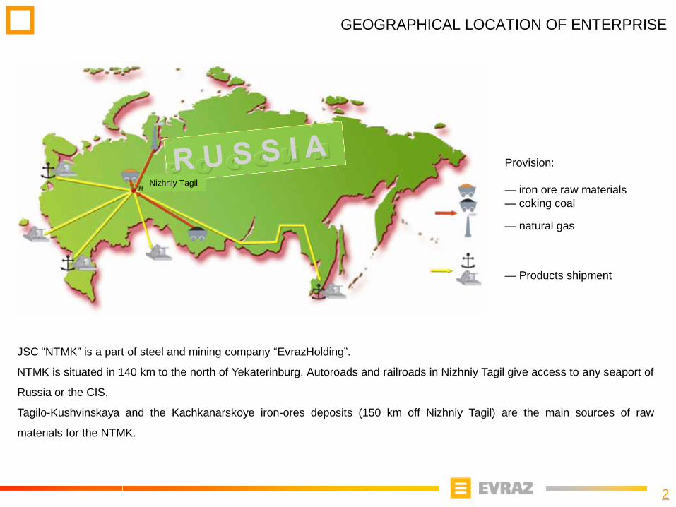
JSC “NTMK” is a part of steel and mining company “EvrazHolding”.
NTMK is situated in 140 km to the north of Yekaterinburg. Autoroads and railroads in Nizhniy Tagil give access to any seaport of
Russia or the CIS.
Tagilo-Kushvinskaya and the Kachkanarskoye iron-ores deposits (150 km off Nizhniy Tagil) are the main sources of raw
materials for the NTMK.
Provision:
— iron ore raw materials— coking coal
— natural gas
— Products shipment
Nizhniy Tagil

3
COMPANY’S ORE DEPOSIT
KGOK’s performance, thousand tons per year 2009 2015
Extraction of raw materials 57 200 63 000
Production of iron ore ,total 9 870 10 878
sinter 3 360 3 988
pellets 6 210 6 890
Ore extraction on Kachkanarsky mining and dressing
complex (KGOK) is done from open quarries. The special
feature of Kachkanarskiy’s titaniferous magnetites is
presence of 0,45 – 0,60% vanadium pentoxide, which
allows for natural steel microalloying. Besides they contain
significant quantity of titan dioxide (2,5 – 3,4%) that
defines specific difficulties in operations of blast furnaces
with this raw material.
Chemistry of KGOK’s raw material
Materials Chemistry, mass %
Fe general FeO Fe2О3 S P V2O5 TiO2
Sinter 54,09 8,86 60,34 0,015 0,006 0,50 2,06
Pellets 60,99 3,48 74,98 0,006 0,005 0,56 2,25
4
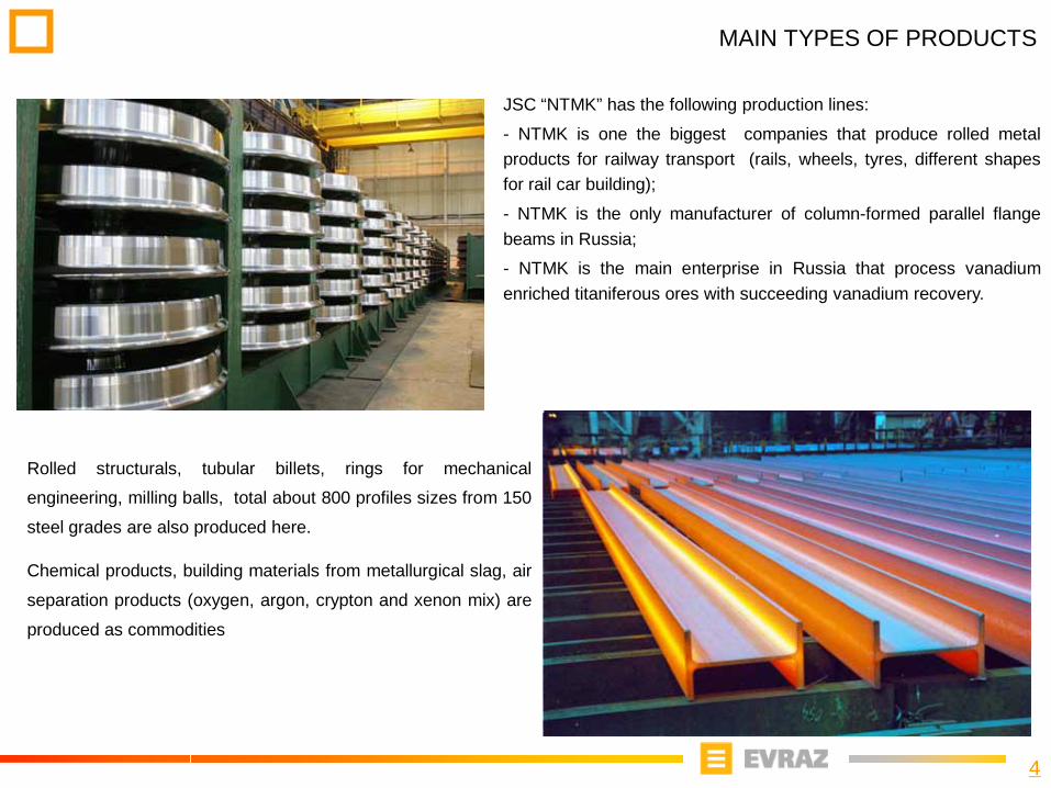
JSC “NTMK” has the following production lines:
- NTMK is one the biggest companies that produce rolled metalproducts for railway transport (rails, wheels, tyres, different shapesfor rail car building);
- NTMK is the only manufacturer of column-formed parallel flangebeams in Russia;
- NTMK is the main enterprise in Russia that process vanadiumenriched titaniferous ores with succeeding vanadium recovery.
MAIN TYPES OF PRODUCTS
Rolled structurals, tubular billets, rings for mechanical
engineering, milling balls, total about 800 profiles sizes from 150
steel grades are also produced here.
Chemical products, building materials from metallurgical slag, air
separation products (oxygen, argon, crypton and xenon mix) are
produced as commodities
5
COMPANY”S STRUCTURE
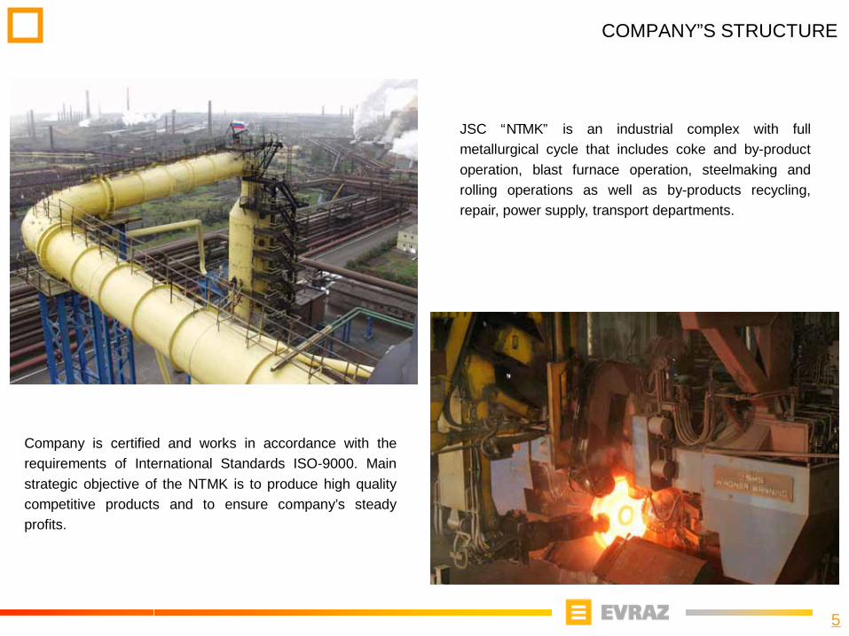
JSC “NTMK” is an industrial complex with fullmetallurgical cycle that includes coke and by-productoperation, blast furnace operation, steelmaking androlling operations as well as by-products recycling,repair, power supply, transport departments.
Company is certified and works in accordance with therequirements of International Standards ISO-9000. Mainstrategic objective of the NTMK is to produce high qualitycompetitive products and to ensure company’s steadyprofits.
6
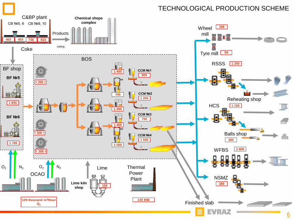
TECHNOLOGICAL PRODUCTION SCHEME
HCS
RSSS
Balls shop
Reheating shop
WFBS
Tyre mill
Finished slab
Wheel mill
BF №6
BF №5
BF shop
Coke
Chemical shops complexCB №5, 6
C&BP plantCB №9, 10
OCAO
1 600
168
736 833453453
1 835
1 765
Lime kiln shop 150
LimeО2 N2О2 N2
84
Products
coking
1 200
1 100
184
Thermal Power Plant
129 thousand m3/hourО2
140 MW
280NSMZ
CCM №3
BOS
CCM №2
CCM №1800
700
1 200
1 500
1 300 т
1 300 т
1 300 т
CCM №4
1 400
1 400
1 400
1 500
700
7
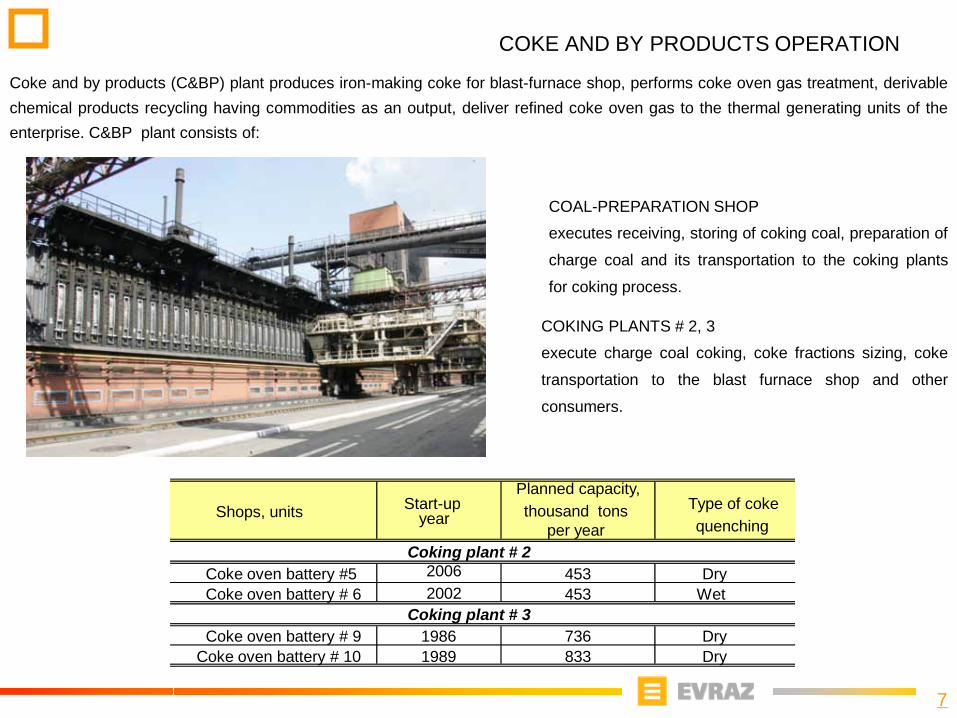
COKE AND BY PRODUCTS OPERATION
Coke and by products (C&BP) plant produces iron-making coke for blast-furnace shop, performs coke oven gas treatment, derivablechemical products recycling having commodities as an output, deliver refined coke oven gas to the thermal generating units of theenterprise. C&BP plant consists of:
COKING PLANTS # 2, 3
execute charge coal coking, coke fractions sizing, coke
transportation to the blast furnace shop and other
consumers.
COAL-PREPARATION SHOP
executes receiving, storing of coking coal, preparation of
charge coal and its transportation to the coking plants
for coking process.
Shops, units Start-upyear
Planned capacity,thousand tons
per year
Type of cokequenching
Coke oven battery #5 2006 453 DryCoke oven battery # 6 2002 453 Wet
Coke oven battery # 9 1986 736 DryCoke oven battery # 10 1989 833 Dry
Coking plant # 2
Coking plant # 3

8
COKE AND BY PRODUCTS OPERATION
BY PRODUCTS RECOVERY PLANTS #2, 3
Coke oven gas treatment from coal-tar pitch, ammonia, benzene
carbohydrates, light pyridine compounds.
Ammonia sulphate commodities shipment.
Derivable chemical products transportation to the recycling plants.
Delivery of refined coke oven gas to the thermal generating units of
the enterprise.
RECYCLING PLANTS (pitch distillation plant, coke pitch plant, pyridinebases plant)Recycling of chemical products derived from coke oven gas andcommodity goods output.
9
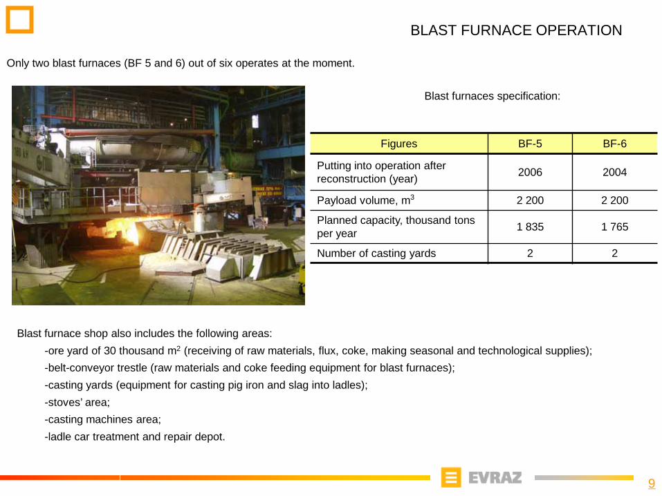
BLAST FURNACE OPERATION
Only two blast furnaces (BF 5 and 6) out of six operates at the moment.
Blast furnace shop also includes the following areas:-ore yard of 30 thousand m2 (receiving of raw materials, flux, coke, making seasonal and technological supplies);-belt-conveyor trestle (raw materials and coke feeding equipment for blast furnaces);-casting yards (equipment for casting pig iron and slag into ladles);-stoves’ area;-casting machines area;-ladle car treatment and repair depot.
Blast furnaces specification:
Figures BF-5 BF-6
Putting into operation after reconstruction (year) 2006 2004
Payload volume, m3 2 200 2 200
Planned capacity, thousand tons per year 1 835 1 765
Number of casting yards 2 2
10
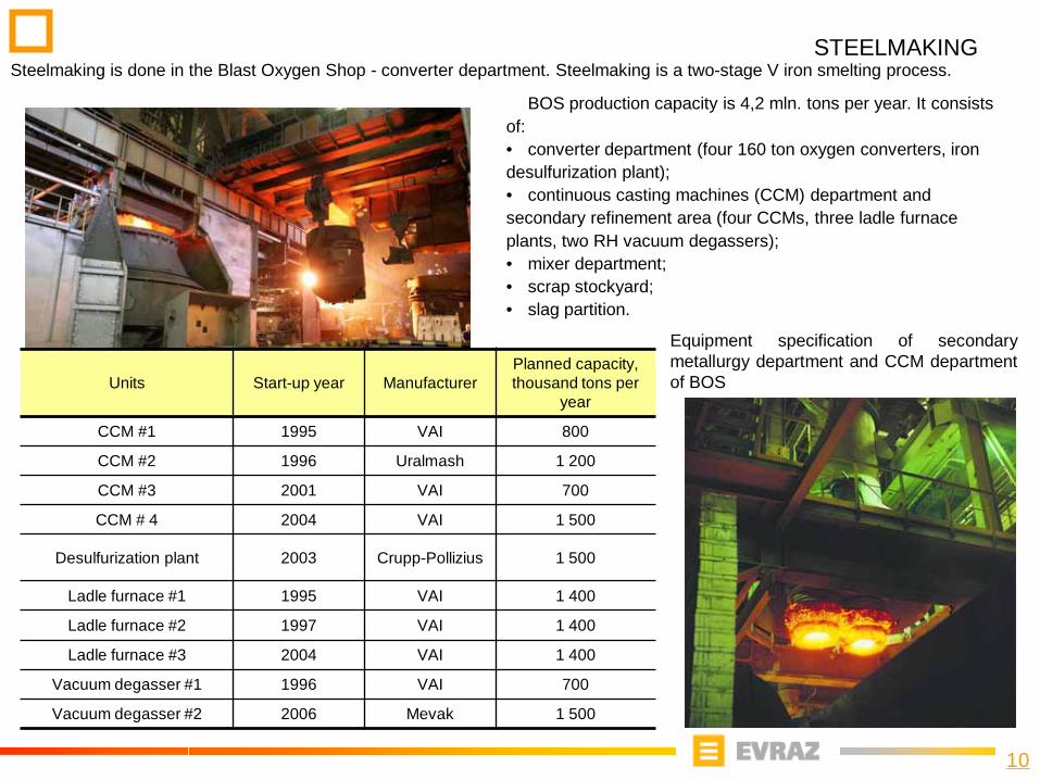
STEELMAKINGSteelmaking is done in the Blast Oxygen Shop - converter department. Steelmaking is a two-stage V iron smelting process.
BOS production capacity is 4,2 mln. tons per year. It consists of: • converter department (four 160 ton oxygen converters, iron desulfurization plant);• continuous casting machines (CCM) department andsecondary refinement area (four CCMs, three ladle furnace plants, two RH vacuum degassers);• mixer department;• scrap stockyard;• slag partition.
Equipment specification of secondarymetallurgy department and CCM departmentof BOSUnits Start-up year Manufacturer
Planned capacity, thousand tons per
year
CCM #1 1995 VAI 800
CCM #2 1996 Uralmash 1 200
CCM #3 2001 VAI 700
CCM # 4 2004 VAI 1 500
Desulfurization plant 2003 Crupp-Pollizius 1 500
Ladle furnace #1 1995 VAI 1 400
Ladle furnace #2 1997 VAI 1 400
Ladle furnace #3 2004 VAI 1 400
Vacuum degasser #1 1996 VAI 700
Vacuum degasser #2 2006 Mevak 1 500
11
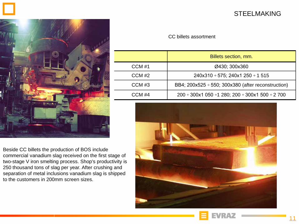
STEELMAKING
Billets section, mm.
CCM #1 Ø430; 300х360
CCM #2 240х310 ÷ 575; 240х1 250 ÷ 1 515
CCM #3 ВВ4; 200х525 ÷ 550; 300х380 (after reconstruction)
CCM #4 200 ÷ 300х1 050 ÷1 280; 200 ÷ 300х1 500 ÷ 2 700
CC billets assortment
Beside CC billets the production of BOS include commercial vanadium slag received on the first stage of two-stage V iron smelting process. Shop’s productivity is 250 thousand tons of slag per year. After crushing and separation of metal inclusions vanadium slag is shipped to the customers in 200mm screen sizes.
12
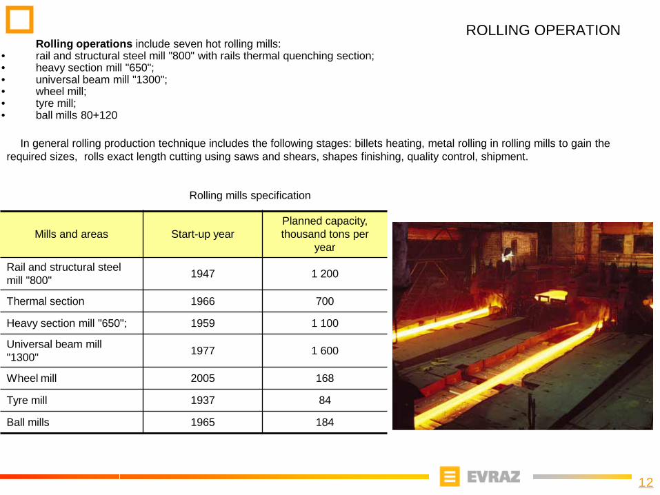
ROLLING OPERATION
In general rolling production technique includes the following stages: billets heating, metal rolling in rolling mills to gain the required sizes, rolls exact length cutting using saws and shears, shapes finishing, quality control, shipment.
Rolling operations include seven hot rolling mills:• rail and structural steel mill "800" with rails thermal quenching section;• heavy section mill "650";• universal beam mill "1300";• wheel mill;• tyre mill;• ball mills 80+120
Rolling mills specification
Mills and areas Start-up yearPlanned capacity, thousand tons per
year
Rail and structural steel mill "800" 1947 1 200
Thermal section 1966 700
Heavy section mill "650"; 1959 1 100
Universal beam mill"1300" 1977 1 600
Wheel mill 2005 168
Tyre mill 1937 84
Ball mills 1965 184
13
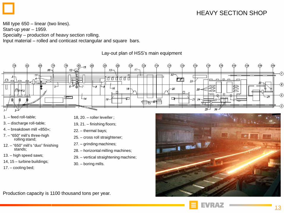
HEAVY SECTION SHOPMill type 650 – linear (two lines).Start-up year – 1959.Specialty – production of heavy section rolling.Input material – rolled and conticast rectangular and square bars.
Production capacity is 1100 thousand tons per year.
Lay-out plan of HSS’s main equipment
1. – feed roll-table;3. – discharge roll-table;4. – breakdown mill «850»;7. – “650” mill’s three-high
rolling stand;12. – “650” mill’s “duo” finishing
stands;13. – high speed saws;14, 15 – turbine buildings;17. – cooling bed;
18, 20. – roller leveller ;
19, 21. – finishing floors;
22. – thermal bays;
25. – cross roll straightener;
27. – grinding machines;
28. – horizontal milling machines;
29. – vertical straightening machine;
30. – boring mills.
14
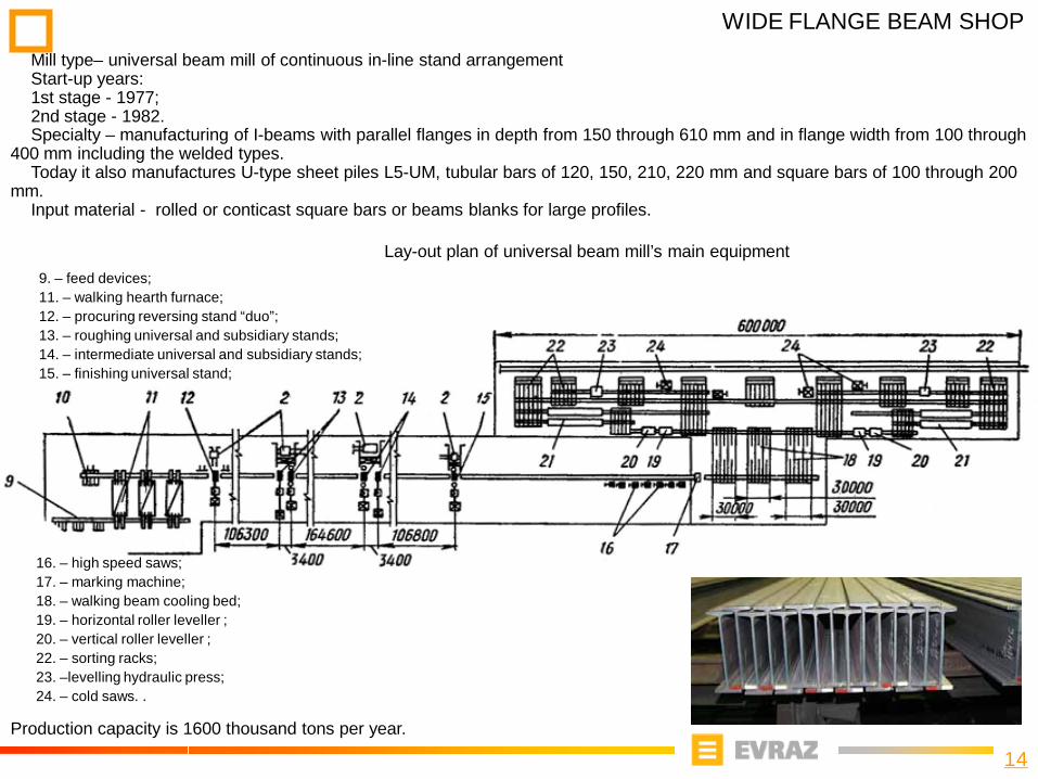
WIDE FLANGE BEAM SHOPMill type– universal beam mill of continuous in-line stand arrangement Start-up years:1st stage - 1977; 2nd stage - 1982.Specialty – manufacturing of I-beams with parallel flanges in depth from 150 through 610 mm and in flange width from 100 through
400 mm including the welded types. Today it also manufactures U-type sheet piles L5-UM, tubular bars of 120, 150, 210, 220 mm and square bars of 100 through 200
mm.Input material - rolled or conticast square bars or beams blanks for large profiles.
Production capacity is 1600 thousand tons per year.
9. – feed devices;11. – walking hearth furnace;12. – procuring reversing stand “duo”;13. – roughing universal and subsidiary stands;14. – intermediate universal and subsidiary stands;15. – finishing universal stand;
16. – high speed saws;17. – marking machine;18. – walking beam cooling bed;19. – horizontal roller leveller ;20. – vertical roller leveller ;22. – sorting racks;23. –levelling hydraulic press;24. – cold saws. .
Lay-out plan of universal beam mill’s main equipment
15
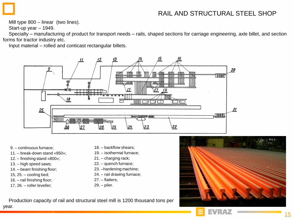
RAIL AND STRUCTURAL STEEL SHOPMill type 800 – linear (two lines). Start-up year – 1949.Specialty – manufacturing of product for transport needs – rails, shaped sections for carriage engineering, axle billet, and section
forms for tractor industry etc.Input material – rolled and conticast rectangular billets.
Production capacity of rail and structural steel mill is 1200 thousand tons per year.
9. – continuous furnace;11. – break-down stand «950»;12. – finishing stand «800»;13. – high speed saws;14. – beam finishing floor;15, 25. – cooling bed;16. – rail finishing floor;17, 26. – roller leveller;
18. – backflow shears;19. – isothermal furnace;21. – charging rack;22. – quench furnace;23. –hardening machine;24. – rail drawing furnace; 27. – flatters;29. – piler.
16
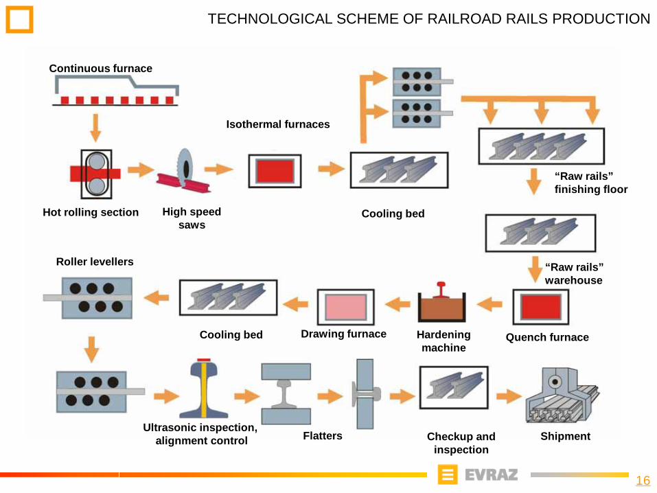
TECHNOLOGICAL SCHEME OF RAILROAD RAILS PRODUCTION
Continuous furnace
Quench furnace
Hot rolling section Cooling bed
Roller levellers
Ultrasonic inspection,alignment control Flatters Checkup and
inspectionShipment
High speed saws
“Raw rails” finishing floor
“Raw rails” warehouse
Drawing furnace Hardening machine
Cooling bed
Isothermal furnaces

17
WHEEL MILL, WHEEL PRODUCTION SCHEME
Pressing and rolling section
5000 т9000 т5000 т
Rolling millHardening units
Machining process train #1
Thermal treatment
Machining process train # 2
Heating furnacesFor hardeningDrawing furnaces
Heating furnacefor working
Painting
Покраска
Final control
Hardness metering
Shot-blasting machine
Shot blasterMeasuring
Shot blasterMeasuring
Products shipment
Cold saws
Final checking line #2
Final checking line #1
Hardness metering
Specialty – manufacturing of wheels and wheel blanks for rolling stock equipment and crane construction.Исходная заготовка - круглая непрерывно-литая заготовка диаметром 430 мм.
Production capacity - 172 thousand tons per year
18
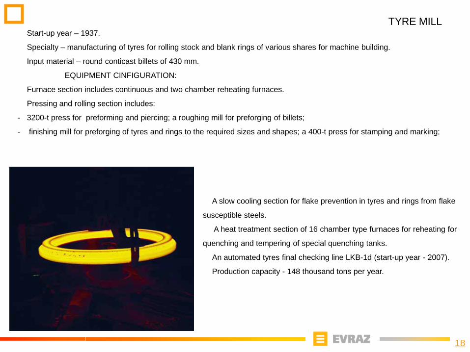
TYRE MILL
A slow cooling section for flake prevention in tyres and rings from flake
susceptible steels.
A heat treatment section of 16 chamber type furnaces for reheating for
quenching and tempering of special quenching tanks.
An automated tyres final checking line LKB-1d (start-up year - 2007).
Production capacity - 148 thousand tons per year.
Start-up year – 1937.
Specialty – manufacturing of tyres for rolling stock and blank rings of various shares for machine building.
Input material – round conticast billets of 430 mm.
EQUIPMENT CINFIGURATION:
Furnace section includes continuous and two chamber reheating furnaces.
Pressing and rolling section includes:
- 3200-t press for preforming and piercing; a roughing mill for preforging of billets;
- finishing mill for preforging of tyres and rings to the required sizes and shapes; a 400-t press for stamping and marking;
19
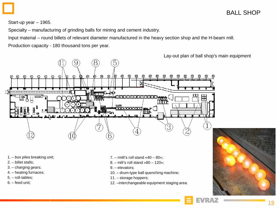
BALL SHOPStart-up year – 1965.
Specialty – manufacturing of grinding balls for mining and cement industry.
Input material – round billets of relevant diameter manufactured in the heavy section shop and the H-beam mill.
Production capacity - 180 thousand tons per year.
1. – box piles breaking unit;2. – billet stalls;3. – charging gears;4. – heating furnaces;5. – roll-tables;6. – feed unit;
7. – rmill’s roll stand «40 – 80»;8. – mill’s roll stand «80 – 120»;9. – elevators;10. – drum-type ball quenching machine;11. – storage hoppers;12. –interchangeable equipment staging area.
Lay-out plan of ball shop’s main equipment
20
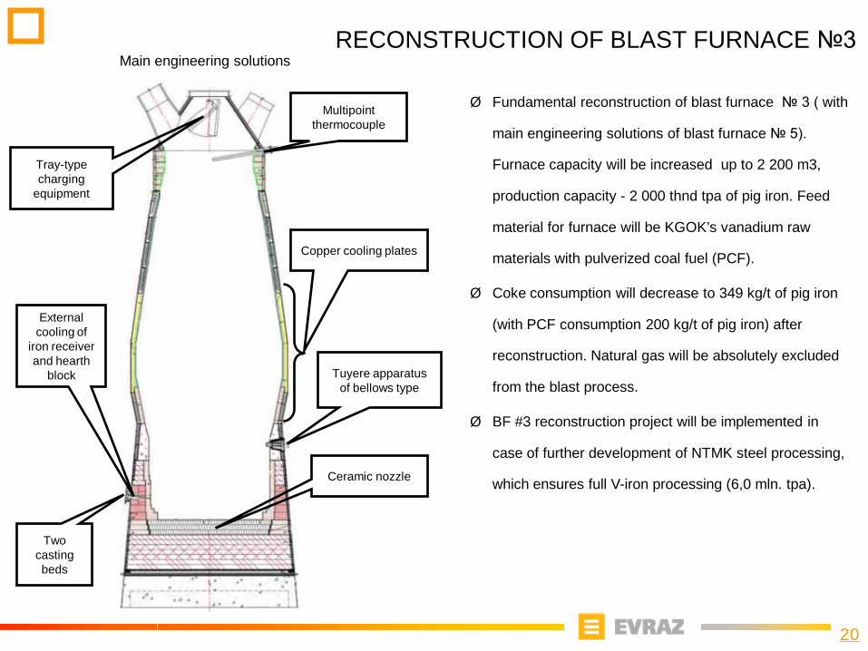
RECONSTRUCTION OF BLAST FURNACE №3
Tray-type charging
equipment
Tuyere apparatus of bellows type
Two casting beds
Ceramic nozzle
Copper cooling plates
External cooling of
iron receiver and hearth
block
Multipoint thermocouple
Ø Fundamental reconstruction of blast furnace № 3 ( with
main engineering solutions of blast furnace № 5).
Furnace capacity will be increased up to 2 200 m3,
production capacity - 2 000 thnd tpa of pig iron. Feed
material for furnace will be KGOK’s vanadium raw
materials with pulverized coal fuel (PCF).
Ø Coke consumption will decrease to 349 kg/t of pig iron
(with PCF consumption 200 kg/t of pig iron) after
reconstruction. Natural gas will be absolutely excluded
from the blast process.
Ø BF #3 reconstruction project will be implemented in
case of further development of NTMK steel processing,
which ensures full V-iron processing (6,0 mln. tpa).
Main engineering solutions
21
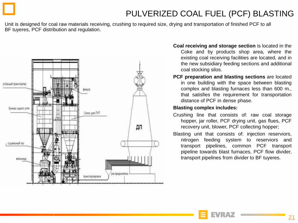
PULVERIZED COAL FUEL (PCF) BLASTINGUnit is designed for coal raw materials receiving, crushing to required size, drying and transportation of finished PCF to all BF tuyeres, PCF distribution and regulation.
Coal receiving and storage section is located in theCoke and by products shop area, where theexisting coal receiving facilities are located, and inthe new subsidiary feeding sections and additionalcoal stocking silos.
PCF preparation and blasting sections are locatedin one building with the space between blastingcomplex and blasting furnaces less than 600 m.,that satisfies the requirement for transportationdistance of PCF in dense phase.
Blasting complex includes:Crushing line that consists of: raw coal storage
hopper, jar roller, PCF drying unit, gas flues, PCFrecovery unit, blower, PCF collecting hopper;
Blasting unit that consists of: injection reserviors,nitrogen feeding system to reserviors andtransport pipelines, common PCF transportpipeline towards blast furnaces, PCF flow divider,transport pipelines from divider to BF tuyeres.
22
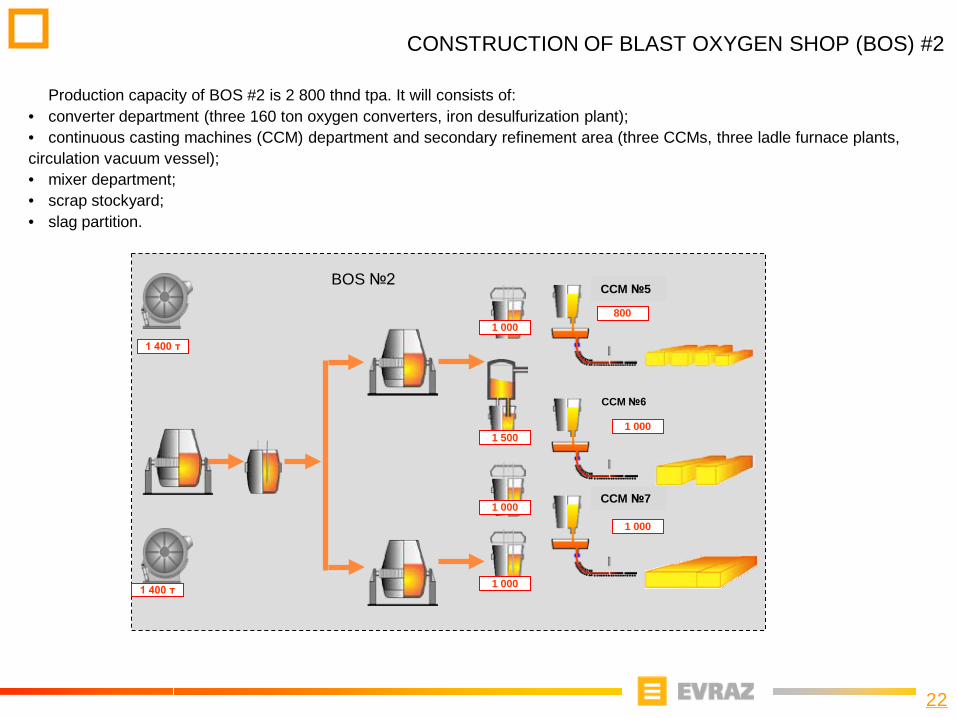
CONSTRUCTION OF BLAST OXYGEN SHOP (BOS) #2
Production capacity of BOS #2 is 2 800 thnd tpa. It will consists of:• converter department (three 160 ton oxygen converters, iron desulfurization plant);• continuous casting machines (CCM) department and secondary refinement area (three CCMs, three ladle furnace plants, circulation vacuum vessel);• mixer department;• scrap stockyard;• slag partition.
МНЛЗ №7
BOS №2
CCM №6
МНЛЗ №5
800
1 000
1 400 т
1 400 т
1 000
1 000
1 000
1 500
1 000
CCM #5
CCM №7
CCM №5
23
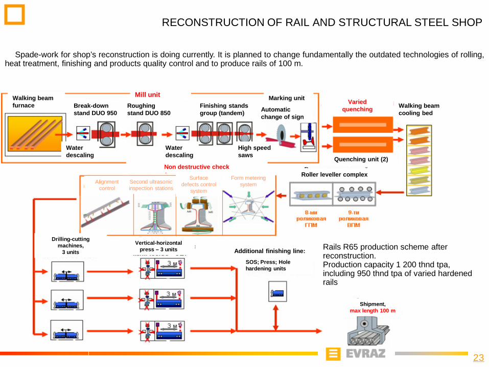
RECONSTRUCTION OF RAIL AND STRUCTURAL STEEL SHOP
Spade-work for shop’s reconstruction is doing currently. It is planned to change fundamentally the outdated technologies of rolling,heat treatment, finishing and products quality control and to produce rails of 100 m.
Rails R65 production scheme after reconstruction.Production capacity 1 200 thnd tpa, including 950 thnd tpa of varied hardened rails
Mill unitWalking beam furnace
Water descaling
Break-down stand DUO 950
Roughing stand DUO 850
Water descaling
Finishing stands group (tandem)
High speed saws
Marking unitWalking beam cooling bed Automatic
change of sign
Varied quenching
Quenching unit (2)
Roller leveller complexNon destructive check
Alignment control
Second ultrasonic inspection stations
Surface defects control
system
Form metering system
Additional finishing line:
SOS; Press; Hole hardening units
Shipment, max length 100 m
Vertical-horizontal press – 3 units
Drilling-cutting machines,
3 units


