
JWST telescope integration and
test progress
Page 1
Gary W. Matthewsa, Tony L. Whitmana, Lee D. Feinbergb, Mark F.
Voytonb, Juli A. Landerb, Ritva Keski-Kuhab
a – Harris Corporation
b – NASA Goddard Space Flight Center
SPIE XXXX-XX
June 2016
OTIS AI&T Status
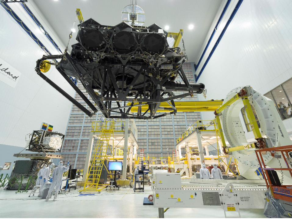
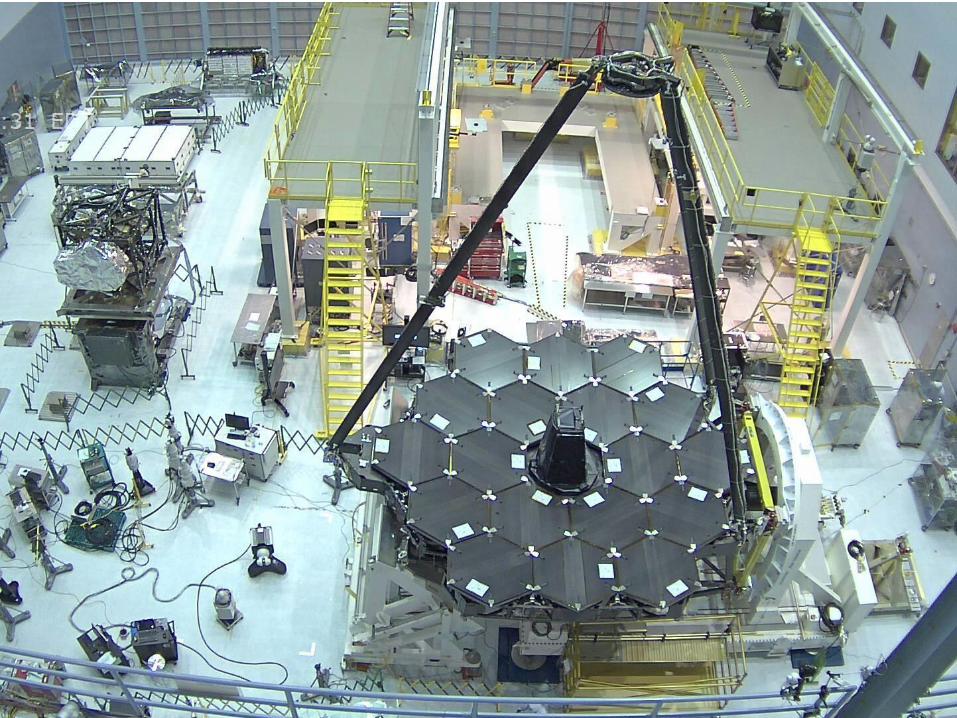
Telescope Test Activities
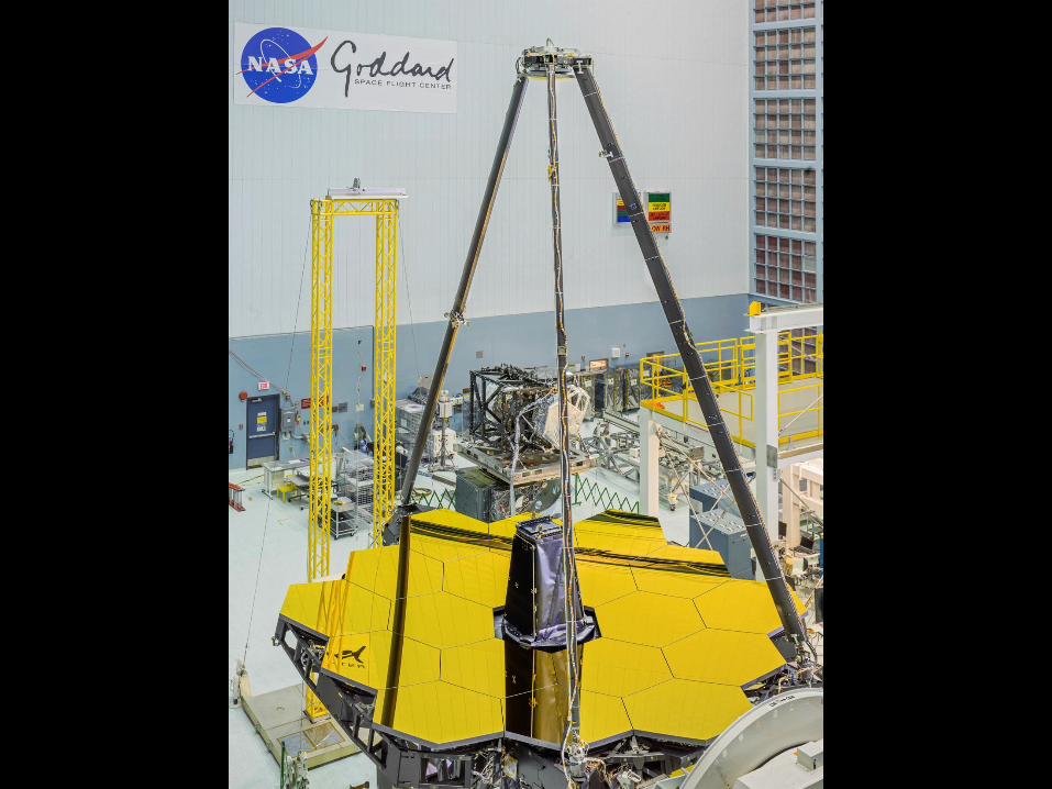
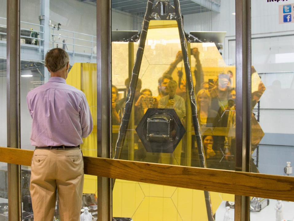
– Optical Telescope Element (OTE) and OTE/ISIM (OTIS) integration will occur at
GSFC in the large SSDIF clean room
– Most of OTE Optical Ground Support Equipment (OGSE) has been completed
and was used for Pathfinder integration operations
Pathfinder OGSE Test Program
– A series of three cryo tests planned prior to the flight that increase in complexity
and designed to cover all aspects of the flight test program
- CCT – Chamber Commissioning with the OGSE installed - Complete
- OGSE#1 – Center of Curvature and Dynamic Testing - Complete
- OGSE#2 – Half Pass and Pass and a Half Testing
- Thermal Pathfinder (TPF) – OTIS Thermal Simulation
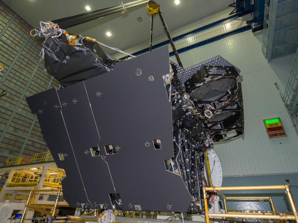
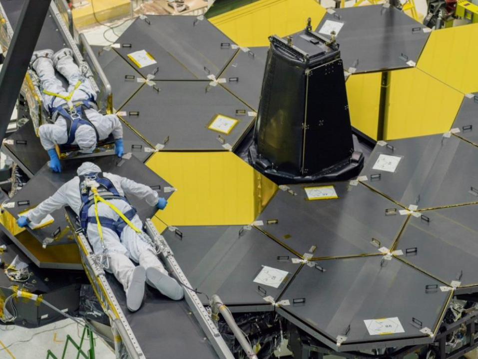
Optical Telescope Element (OTE) Integration
– Optical integration of the flight OTE scheduled for Fall 2015
Page 2

This document is not subject to the controls of the International Traffic in Arms Regulations (ITAR) or the Export Administration Regulations (EAR). Page 3

This document is not subject to the controls of the International Traffic in Arms Regulations (ITAR) or the Export Administration Regulations (EAR). Page 4
This document is not subject to the controls of the International Traffic in Arms Regulations (ITAR) or the Export Administration Regulations (EAR). Page 5
This document is not subject to the controls of the International Traffic in Arms Regulations (ITAR) or the Export Administration Regulations (EAR). Page 6

This document is not subject to the controls of the International Traffic in Arms Regulations (ITAR) or the Export Administration Regulations (EAR). Page 7
This document is not subject to the controls of the International Traffic in Arms Regulations (ITAR) or the Export Administration Regulations (EAR). Page 8
This document is not subject to the controls of the International Traffic in Arms Regulations (ITAR) or the Export Administration Regulations (EAR). Page 9
This document is not subject to the controls of the International Traffic in Arms Regulations (ITAR) or the Export Administration Regulations (EAR). Page 10
This document is not subject to the controls of the International Traffic in Arms Regulations (ITAR) or the Export Administration Regulations (EAR). Page 11

This document is not subject to the controls of the International Traffic in Arms Regulations (ITAR) or the Export Administration Regulations (EAR). Page 12
This document is not subject to the controls of the International Traffic in Arms Regulations (ITAR) or the Export Administration Regulations (EAR). Page 13

This document is not subject to the controls of the International Traffic in Arms Regulations (ITAR) or the Export Administration Regulations (EAR). Page 14

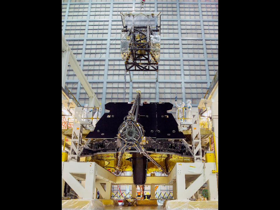
JSC Optical GSE
Work continues at JSC to prepare for the OTIS cryo test
First series of tests were optical based tests
– Check out of the optical ground support equipment
– Increasing complexity for the optical equipment
Excellent optical results with many lessons learned
Page 15
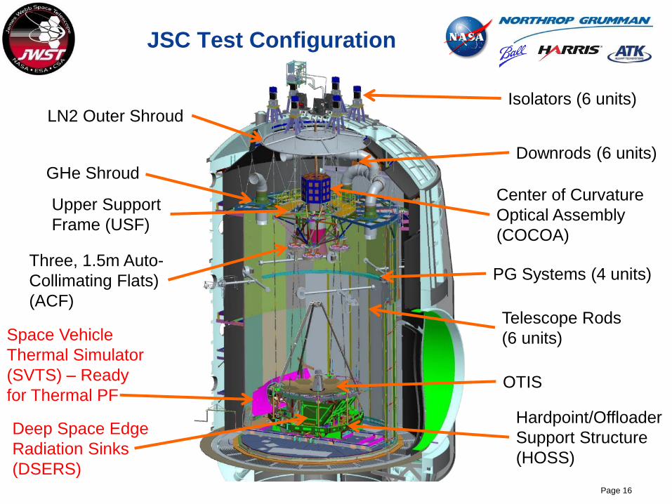
JSC Test Configuration
Page 16
Three, 1.5m Auto-
Collimating Flats)
(ACF)
PG Systems (4 units)
Telescope Rods
(6 units)
OTIS
Hardpoint/Offloader
Support Structure
(HOSS)
Center of Curvature
Optical Assembly
(COCOA)
Isolators (6 units)
Upper Support
Frame (USF)
GHe Shroud
LN2 Outer Shroud
Downrods (6 units)
Space Vehicle
Thermal Simulator
(SVTS) – Ready
for Thermal PF
Deep Space Edge
Radiation Sinks
(DSERS)

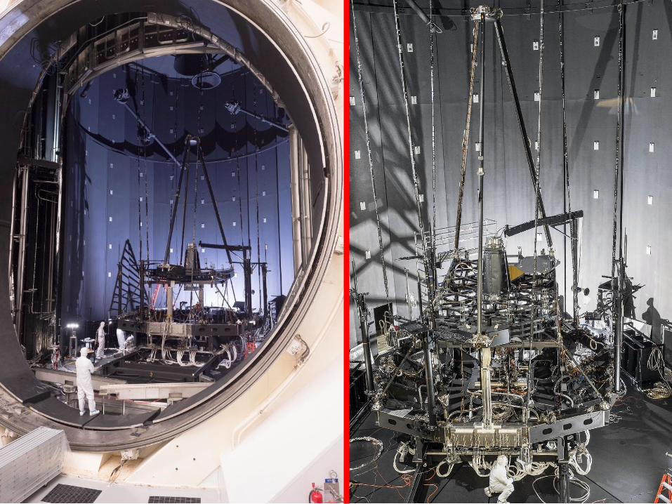
OGSE Test Program
• Checkout Optical GSE that
has not seen cryo before:
CoC test, Hanging Config,
Photogrammetry
• No flight hardware except
flight spare PMSA/SMA
• Dynamics and Thermal
Distortion portion of PF
Augmentation occur here
• Thermal GSE Checkout
(includes SVTS)
• Dry run cooldown and
warmup
• Will allow risk reduction of
some OTE Thermal
Balance (design validation
off the critical path)
• Checkout Pass and a
half test with flight
AOS and GSE source
plate system
• Uses BIA camera as
SI simulator
OGSE-1
Complete
Pathfinder Thermal OGSE-2
Complete PF Updated
to be more Flight Like
17
PMSA
Simulator
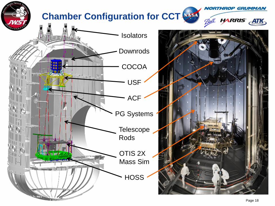
Chamber Configuration for CCT
Page 18
ACF
PG Systems
Telescope
Rods
OTIS 2X
Mass Sim
HOSS
COCOA
Isolators
USF
Downrods
This document is not subject to the controls of the International Traffic in Arms Regulations (ITAR) or the Export Administration Regulations (EAR). Page 19
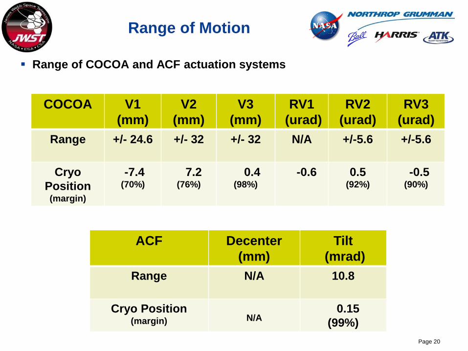
Range of Motion
Range of COCOA and ACF actuation systems
Page 20
COCOA V1
(mm)
V2
(mm)
V3
(mm)
RV1
(urad)
RV2
(urad)
RV3
(urad)
Range +/- 24.6 +/- 32 +/- 32 N/A +/-5.6 +/-5.6
Cryo
Position (margin)
-7.4 (70%)
7.2 (76%)
0.4 (98%)
-0.6 0.5 (92%)
-0.5 (90%)
ACF Decenter
(mm)
Tilt
(mrad)
Range N/A 10.8
Cryo Position (margin) N/A
0.15
(99%)
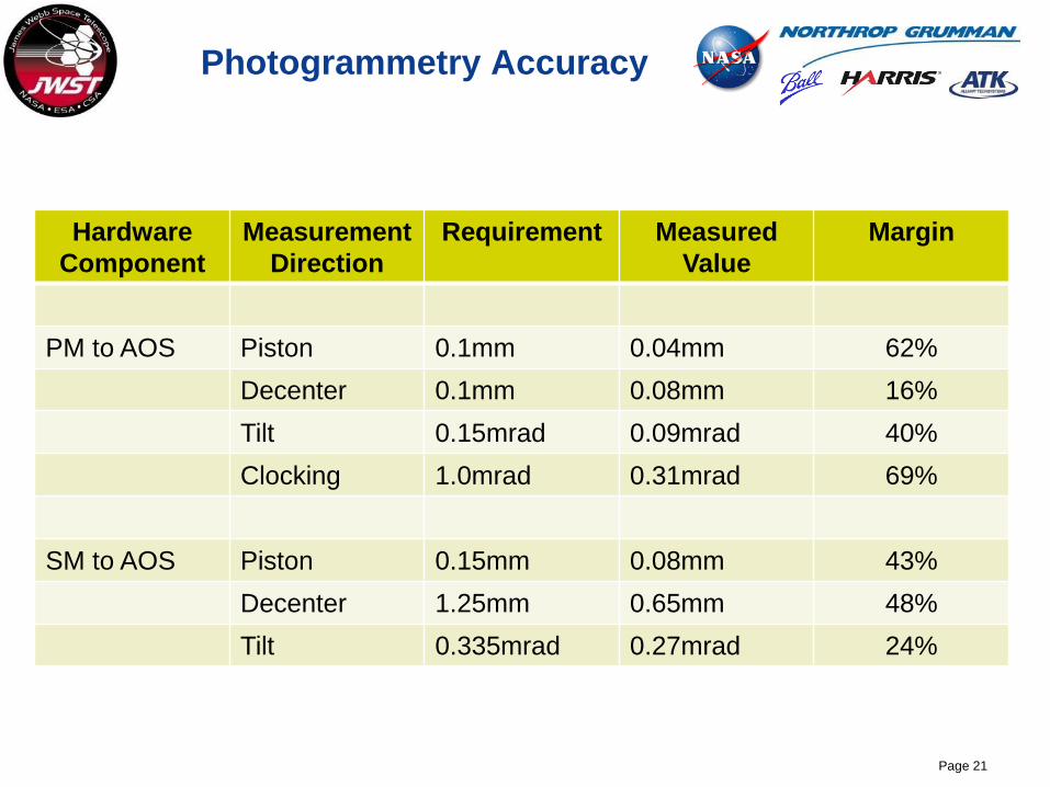
Photogrammetry Accuracy
Hardware
Component
Measurement
Direction
Requirement Measured
Value
Margin
PM to AOS Piston 0.1mm 0.04mm 62%
Decenter 0.1mm 0.08mm 16%
Tilt 0.15mrad 0.09mrad 40%
Clocking 1.0mrad 0.31mrad 69%
SM to AOS Piston 0.15mm 0.08mm 43%
Decenter 1.25mm 0.65mm 48%
Tilt 0.335mrad 0.27mrad 24%
Page 21
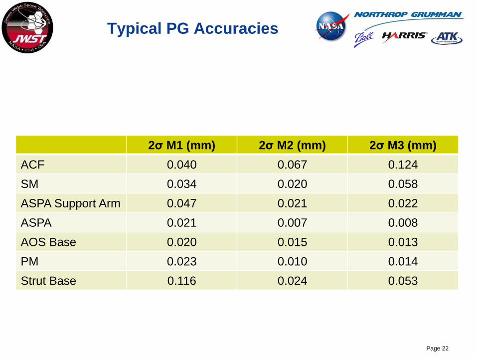
Typical PG Accuracies
2σ M1 (mm) 2σ M2 (mm) 2σ M3 (mm)
ACF 0.040 0.067 0.124
SM 0.034 0.020 0.058
ASPA Support Arm 0.047 0.021 0.022
ASPA 0.021 0.007 0.008
AOS Base 0.020 0.015 0.013
PM 0.023 0.010 0.014
Strut Base 0.116 0.024 0.053
Page 22
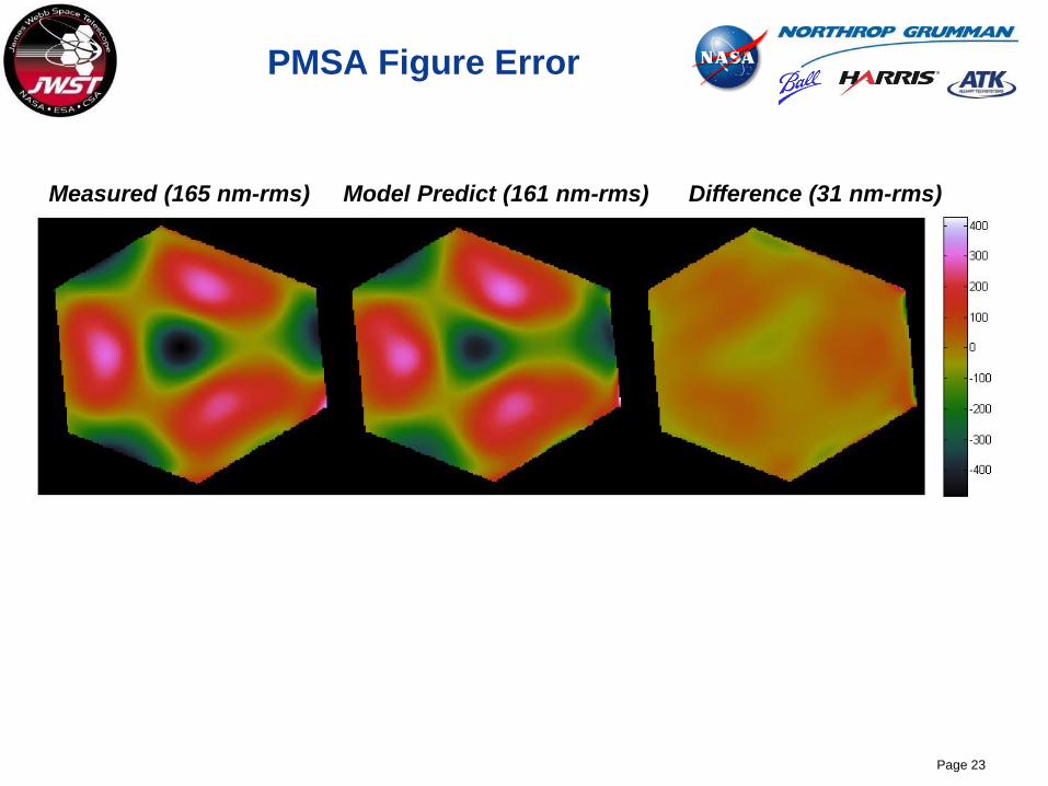
PMSA Figure Error
Page 23
Measured (165 nm-rms) Model Predict (161 nm-rms) Difference (31 nm-rms)

Inward Source Light Path
Page 24
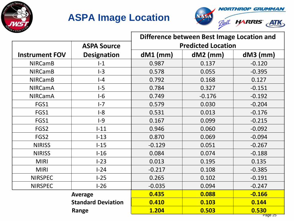
ASPA Image Location
Page 25
Difference between Best Image Location and Predicted Location
Instrument FOV ASPA Source Designation dM1 (mm) dM2 (mm) dM3 (mm)
NIRCamB I-1 0.987 0.137 -0.120
NIRCamB I-3 0.578 0.055 -0.395 NIRCamB I-4 0.792 0.168 0.127
NIRCamA I-5 0.784 0.327 -0.151 NIRCamA I-6 0.749 -0.176 -0.192
FGS1 I-7 0.579 0.030 -0.204
FGS1 I-8 0.531 0.013 -0.176 FGS1 I-9 0.167 0.099 -0.215
FGS2 I-11 0.946 0.060 -0.092 FGS2 I-13 0.870 0.069 -0.094
NIRISS I-15 -0.129 0.051 -0.267 NIRISS I-16 0.084 0.074 -0.188 MIRI I-23 0.013 0.195 0.135
MIRI I-24 -0.217 0.108 -0.385 NIRSPEC I-25 0.265 0.102 -0.191
NIRSPEC I-26 -0.035 0.094 -0.247
Average Standard Deviation
0.435 0.088 -0.166
0.410 0.103 0.144 Range 1.204 0.503 0.530

Hartmann Test Sensivity
Page 26
Baseline
Hartmann
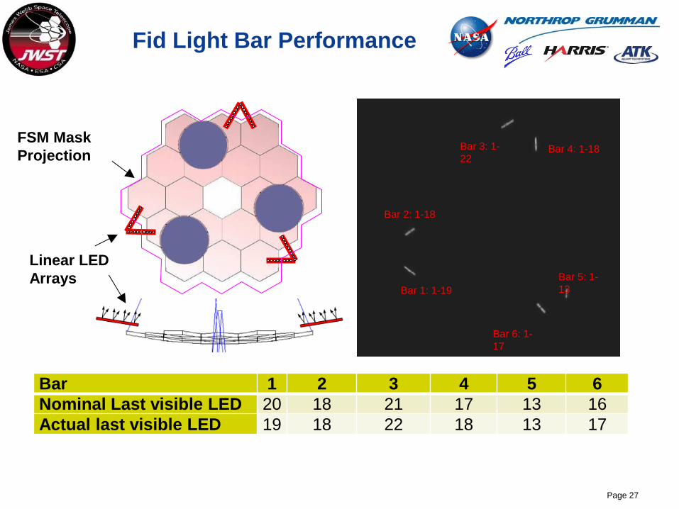
Fid Light Bar Performance
Page 27
Linear LED
Arrays
FSM Mask
Projection
Bar 1: 1-19
Bar 2: 1-18
Bar 6: 1-
17
Bar 5: 1-
13
Bar 4: 1-18 Bar 3: 1-
22
Bar 1 2 3 4 5 6 Nominal Last visible LED 20 18 21 17 13 16 Actual last visible LED 19 18 22 18 13 17

Shadowgram Test
Page 28
Thermal Pathfinder (TPF) Test
Final test prior to OTIS is thermally focused
– How does the system cool down with an OTIS simulator
Incorporation of all the thermal hardware
– DSERS
– SVTS
– Zero-Q heaters
– Actively cooled ACF’s due to “no He gas” for the OTIS test
Page 29

This document is not subject to the controls of the International Traffic in Arms Regulations (ITAR) or the Export Administration Regulations (EAR). Page 30
This document is not subject to the controls of the International Traffic in Arms Regulations (ITAR) or the Export Administration Regulations (EAR). Page 31
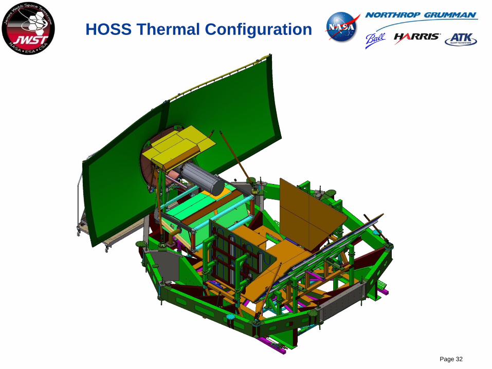
HOSS Thermal Configuration
Page 32
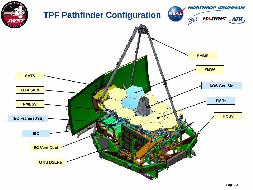
TPF Pathfinder Configuration
Page 33
PMBSS
PMSA
OTIS DSERs
SVTS
IEC Vent Duct
PMBs
AOS Geo Sim
SMMS
HOSS IEC-Frame (DSS)
IEC
DTA Stub
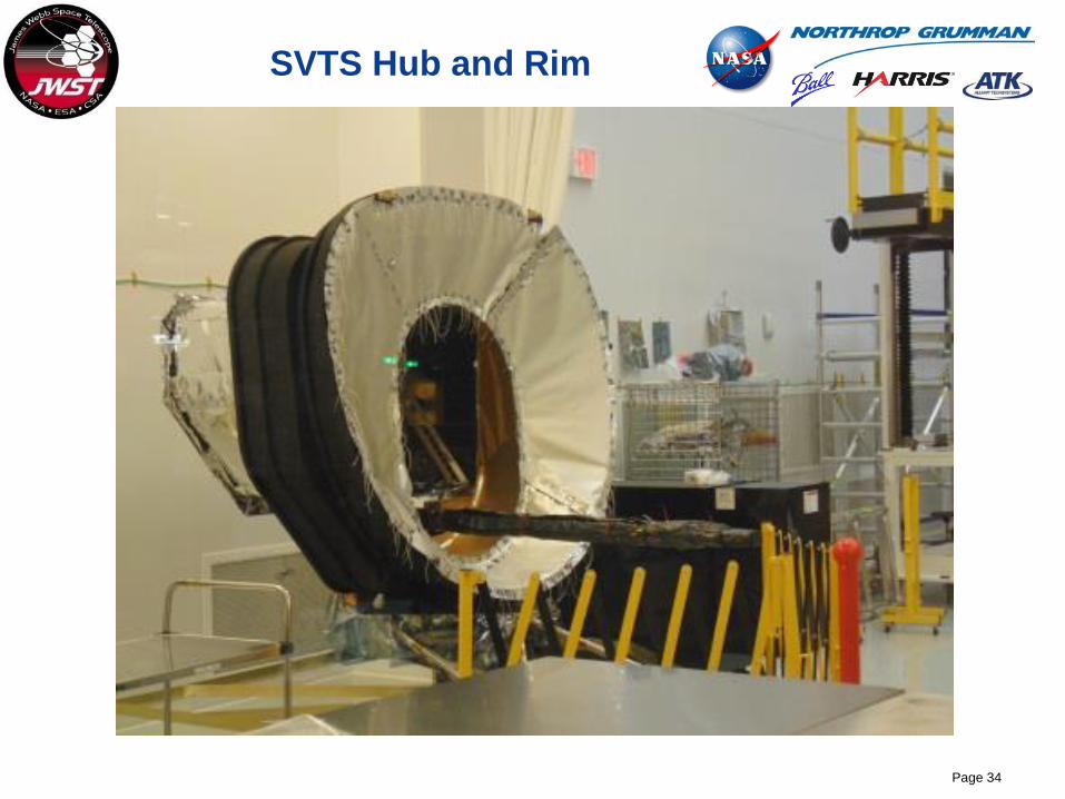
SVTS Hub and Rim
Page 34

Summary
The first of three Optical Ground Support Equipment and Thermal Tests is
complete
Test results have been excellent
– COCOA works as designed
- The two PMSA’s were phased
– PG system is fully operational
– Isolation system worked as designed
- Short during cryo temperatures identified and will be corrected prior to
OGSE#2
Pathfinder has been very important and enables the flight program
– Provides critical experience in preparation for the critical path flight
program
– Well worth the investment by the program
Page 35


