
Key Challenges andOpportunities in Developing theAltair Lunar Lander
John F. ConnollyVehicle Engineering ManagerAltair Project OfficeJohnson Space Center

Page 2
The Integrated Challenge
…that fulfills the policy direction of NASA’s strategicplan, Congressional Authorization Acts, and
Administrative/ OMB policy and budget guidance
Create a lander design based onthe limitations of physics and
human performance…
…that balances performance, cost,risk and reliability of the lander
project, and
…that exists within the integrated architecture performance, cost profile, schedule, and
integrated risk/ reliability targets ofthe Constellation Program, and

Lunar Lander Basics
♦ Lander must perform large delta-Vmaneuvers• ~1000 m/sec Lunar Orbit Insertion• ~2000 m/sec Descent and Landing• ~2000 m/sec Ascent and Rendezvous
♦ Lander must sustain a crew of 4 for up to7 days on the surface
♦ Lander must meet significant safety andreliability requirements• A significant fraction of Constellation’s LOC
and LOM targets
opportunity use many of the lessonslearned from the Apollo program
challenge the lander “looks like theLM”/ appears to ”lack innovation”/doesn’t resemble the Millennium Falcon
Page 3

Apollo and Altair By the Numbers

Apollo LM and Altair
Apollo LM♦ “Eagle”♦ Some preliminary design studies in
the years leading up to the Apolloprogram
♦ Constraints: schedule, mass, cost♦ ~7 years from start of design to first
crewed flight♦ Performs deorbit, landing, ascent♦ Single configuration (sortie)♦ 4 landing legs♦ 2 stages♦ Crew stands during flight
Altair♦ “Altair” = brightest star in the Eagle
constellation (Aquila)♦ Extensive design studies, especially
over the past 20 years♦ Constraints: Risk, mass, cost,
schedule♦ ~12 years from start of preliminary
design (2008) to scheduled firstcrewed flight (2020)
♦ Performs LOI (with Orion), deorbit,landing, ascent, disposal
♦ Separate modules configurable forsortie, cargo and crewed outpostmission
♦ 4 landing legs♦ 2 stages♦ Crew stands during flight
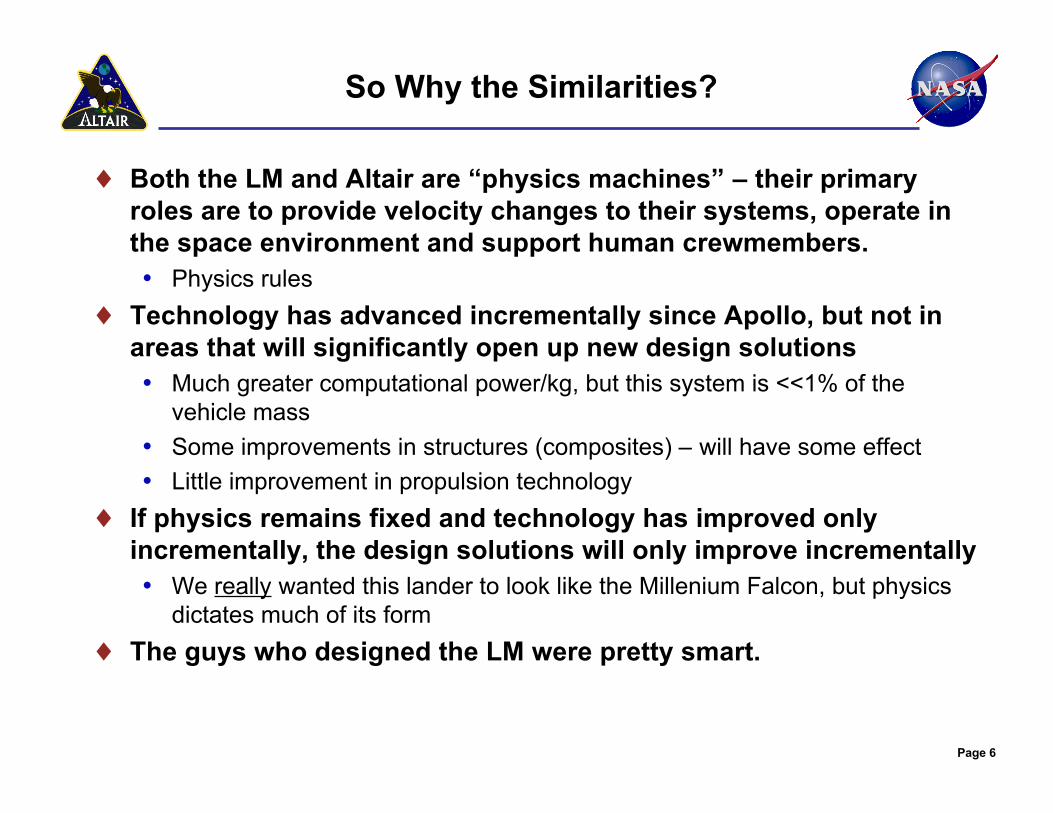
So Why the Similarities?
♦ Both the LM and Altair are “physics machines” – their primaryroles are to provide velocity changes to their systems, operate inthe space environment and support human crewmembers.• Physics rules
♦ Technology has advanced incrementally since Apollo, but not inareas that will significantly open up new design solutions• Much greater computational power/kg, but this system is <<1% of the
vehicle mass• Some improvements in structures (composites) – will have some effect• Little improvement in propulsion technology
♦ If physics remains fixed and technology has improved onlyincrementally, the design solutions will only improve incrementally• We really wanted this lander to look like the Millenium Falcon, but physics
dictates much of its form♦ The guys who designed the LM were pretty smart.
Page 6

Lunar Lander Technical Challenges
♦Do we have the right/optimumdesign? (configuration,innovative solutions,technology choices, lowestmass)Opportunity Current configuration
is an outcome of risk-based designOpportunity 2018 first flight
schedule gives us ampleopportunity to explore innovativeinternal and external configurations
Page 7

8
Lunar Lander Design: Tradeoffs AmongMany Competing Factors
♦ Delta-V – large velocity changes for lunar descent, ascent• Large LOI velocity change with CEV attached
♦ Propellant tank size• Large H2 tanks – packaging challenge
♦ Launch shroud diameter and length• “building a ship in a bottle”
♦ Launch and TLI loads – control buckling, bending and stackfrequencies
♦ c.g. control – packaging propellant, stages and payloads to keepc.g. on/near centerline for vehicle control
♦ Ascent – duration, life support, power, returned payload♦ “Fire in the hole”♦ Abort capabilities throughout all mission phases♦ Crew access (both among modules and to surface)♦ Cargo unloading and access♦ Crew visibility – for landing, docking

Page 9
Lander Concept Timeline
2005 2006Mar. Apr. May June July Aug. Sept. Oct. Nov. Dec. Jan. Feb. Mar. Apr. May June July Aug. Sept. Oct. Nov. Dec. Jan. Feb. Mar. Apr. May June July Aug. Sept. Oct. Nov. Dec. Jan. Feb. Mar. Apr. May June July Aug. Sept. Oct. Nov. Dec.
Lunar LanderOrganizational
Lifecycle
ArchitectureDesignActivity
LanderDesignCycles
LanderConcepts
2007 2008
LAT-1 LAT-2
CxAT-Lunar
LDAC-1
LDAC-1 Δ"M inimum Functional Vehicle"
LDAC-2"M inimum Flyable Vehicle"
Parametric Modeling based on LDAC-1 bottoms-up design
Parametric Modeling based on LDAC-1 Δ bottoms-up design
Parametric Modeling based on LDAC-2 bottoms-up design
LDAC-3"U pgraded Flyable Vehicle"
711-A
p710-A
LSAM Pre-Project Lunar Lander Project
p0610-A
p0611-A
p0612-A
p611-A
p0611-LAT-1p0611-LAT-2
p0702-Ap0702-C
p0701-Ap0701-Bp0701-C
p703-C-Up703-C-C1p703-D-C1
p703-E-Up703-E-C1p703-F-C1
706-A p709-A
p707-A
p707-B
LLPS
p710-B p711-B
Altair Project Office
p711-C
0605-LLPS-10605-LLPS-2
0605-LLPS-30605-LLPS-40605-LLPS-50605-LLPS-6
0605-LLPS-70605-LLPS-80605-LLPS-9
0605-LLPS-100605-LLPS-110605-LLPS-120605-LLPS-13
0605-LLPS-140605-LLPS-150605-LLPS-16
0605-LLPS-170605-LLPS-180605-LLPS-190605-LLPS-20
0605-LLPS-210605-LLPS-220605-LLPS-23
0605-LLPS-240605-LLPS-250605-LLPS-26
0605-LLPS-270605-LLPS-280605-LLPS-290605-LLPS-30
LLPSRFI
0606-LLPS-RFI-10606-LLPS-RFI-2
0606-LLPS-RFI-30606-LLPS-RFI-40606-LLPS-RFI-50606-LLPS-RFI-6
0609-LLPS-1
0609-LLPS-20609-LLPS-30609-LLPS-40609-LLPS-5
0609-LLPS-60609-LLPS-7
50 + parametric
runs in support of
CxAT-Lunar
global
access closure
ESAS
0503-CE&R-10503-CE&R-20503-CE&R-3
0503-CE&R-40503-CE&R-50503-CE&R-6
0503-CE&R-70503-CE&R-80503-CE&R-9
0503-CE&R-10
0503-CE&R-11
CE&R
0507-ESAS-1
ESAS Release
pre-ICPR:
~30 parametric
variations in support of
ICPR requirements
decisions
805-A
p805-Bp0804-Ap0804-Bp0805-C
p0801-Ap0801-Bp0801-C
p0610-LAT-1p0610-LAT-2p0610-LAT-3p0610-LAT-4
0507-ESAS-A0507-ESAS-B
0507-ESAS-C0507-ESAS-D0507-ESAS-E
0507-ESAS-F0507-ESAS-G0507-ESAS-H0507-ESAS-I
0507-ESAS-J
MIT concepts

10
Minimum Functionality/Risk-Informed Design Approach
♦ Altair took a true risk informed design approach, starting with aminimum functionality design and adding from there to reduce risk.
♦ Lunar Design Analysis Cycle (LDAC) 1 developed a “minimumfunctional” vehicle.• “Minimum Functionality” is a design philosophy that begins with a vehicle that will
perform the mission, and no more than that• Does not consider contingencies• Does not have added redundancy (“single string” approach)• Provides early, critical insight into the overall viability of the end-to-end architecture• Provides a starting point to make informed cost/risk trades and consciously buy
down risk• A “Minimum Functionality” vehicle is NOT a design that would ever be
contemplated as a “flyable” design!
♦ LDAC-2 determined the most significant contributors to loss of crew(LOC) and the optimum cost/risk trades to reduce those risks.
♦ LDAC-3 assessed the biggest contributors to loss of mission (LOM) andoptimum cost/risk trades to reduce those risks.
♦ Goal of the design process is to do enough real design work tounderstand and develop the requirements for SRR, and to mature thelander design in-house through SDR.
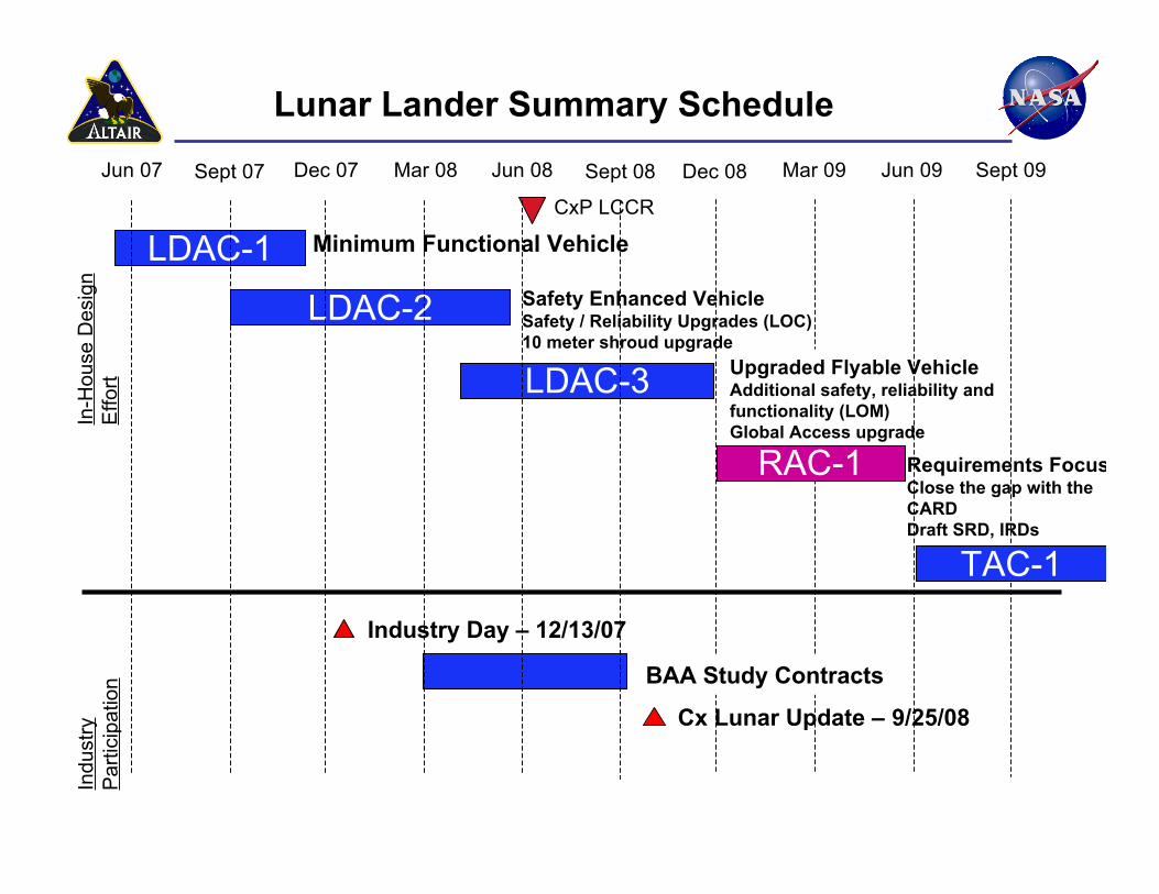
Requirements FocusClose the gap with theCARDDraft SRD, IRDs
Safety Enhanced VehicleSafety / Reliability Upgrades (LOC)10 meter shroud upgrade
Jun 07 Dec 07 Mar 08 Jun 08 Sept 08 Dec 08 Mar 09Sept 07
Lunar Lander Summary Schedule
Minimum Functional Vehicle
LDAC-2Upgraded Flyable VehicleAdditional safety, reliability andfunctionality (LOM)Global Access upgrade
LDAC-1
LDAC-3
CxP LCCR
RAC-1
In-H
ouse
Des
ign
Effo
rt
Jun 09 Sept 09
Industry Day – 12/13/07
BAA Study Contracts
Indu
stry
Par
ticip
atio
n
TAC-1
Cx Lunar Update – 9/25/08

12
Summary LDAC-2 Results:Probability of Loss of Crew, Mass Available for Payload
Note: P(LOC) based on simplified models and identified risk
Events\Hazards Life SupportThermalPropulsionStructures and MechanismsPowerAvionics
Sum of System Contributions to LOC/Mass Available for Payload
0.0E+00
2.0E-02
4.0E-02
6.0E-02
8.0E-02
1.0E-01
1.2E-01
1.4E-01
1.6E-01
1.8E-01
LDAC-1 LDAC-2
P(LO
C)
0
500
1000
1500
2000
2500
3000
3500
4000
mas
s (k
g)
1 in 206
1671 kg
500 kg minimum payload
3652 kg1 in 6
Mass Available for Payload
Individual Subsystem Contribution to LOC:
“Spent” ~ 1.3 t to buydown loss of crew(LOC) risks.
“Spent” an additional680kg on designmaturity.
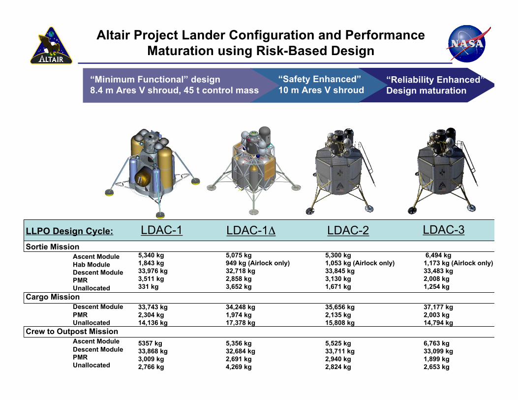
Altair Project Lander Configuration and PerformanceMaturation using Risk-Based Design
LDAC-1 LDAC-1ΔLLPO Design Cycle:Sortie Mission
Ascent ModuleHab ModuleDescent ModulePMRUnallocated
Cargo MissionDescent ModulePMRUnallocated
Crew to Outpost MissionAscent ModuleDescent ModulePMRUnallocated
LDAC-2
“Minimum Functional” design8.4 m Ares V shroud, 45 t control mass
“Safety Enhanced”10 m Ares V shroud
5,340 kg1,843 kg33,976 kg3,511 kg331 kg
33,743 kg2,304 kg14,136 kg
5357 kg33,868 kg3,009 kg2,766 kg
5,075 kg949 kg (Airlock only)32,718 kg2,858 kg3,652 kg
34,248 kg1,974 kg17,378 kg
5,356 kg32,684 kg2,691 kg4,269 kg
5,300 kg1,053 kg (Airlock only)33,845 kg3,130 kg1,671 kg
35,656 kg2,135 kg15,808 kg
5,525 kg33,711 kg2,940 kg2,824 kg
LDAC-3
“Reliability Enhanced”Design maturation
6,494 kg1,173 kg (Airlock only)33,483 kg2,008 kg1,254 kg
37,177 kg2,003 kg14,794 kg
6,763 kg33,099 kg1,899 kg2,653 kg

Upcoming TAC-1 Configuration andMaturation Trades
♦ Alternate Descent Module Configuration Study♦ Alternate Ascent Module & Airlock Configuration Study♦ Alternate AM/DM separation analysis and concepts♦ Design for structural stiffness♦ Descent Module tank residuals♦ Human piloting capability maturation♦ OpsCon/Ops Timeline maturation♦ Refine mass threats list♦ Spacecraft “safe” configuration for critical faults
♦ (27 more prioritized from a master list of 210+ outstanding tasks)
Page 14

Additional Technical Challenges
♦ Descent Main Engine (DME) development• Deep-throttling DME in current ETDP technology portfolio
♦ Multiple-tank liquid level control• Avoid uneven draining of low-density fluids in low acceleration
environments contained in ETDP portfolio♦ Propellant cryo scavanging
• Use residual prop for surface fuel cell power contained in ETDPportfolio
♦ Ascent main engine reliability• Build upon Orion service module engine development
♦ Integrated lander c.g. control♦ Lander Ascent Stage c.g. control♦ Stack Frequency during TLI Burn
• Stiffness of the Altair vehicle, the interface to Orion, and to Ares V
Page 15

Lunar Lander Non-Technical Challenges
♦ Lack of human spacecraft design and development expertise within NASA• We simply don’t have enough turnover of large human spaceflight projects to
consistently train spacecraft developers• Spacecraft are typically developed by industry, with NASA insight/oversight Opportunity Altair taking design past SDR, bringing on contractors to mature the
design Opportunity Use Apollo LM experience, robotic lander experience, STS and ISS
development experience♦ Ramping up a project at the same time that Orion and Ares I are peaking
in development• Competition for resources• Peer projects at different parts of their lifecycles (how to create IRDs, how to keep
requirements from becoming the “problem” of the less mature project)♦ Reserves and Margin
• What is the right level of MGA and PMR for a specific point in a project lifecycle
Page 16

17
Performance Maturity Measure –“Unallocated Differential”
♦ As the Altair design moves through its initial DAC cycles, performance is measuredas “Unallocated Differential” (UD), the difference between basic mass (with MGA)and Control Mass (less PMR)
♦ UD is Altair’s measure of mass consumed by vehicle maturity as the design movesthrough the DACs, from “minimally functional” to “fully functional”
LCCR/MCR
SRR PDR CDR
UDMas
s
Project Lifecycle
40% Total Reserve@ SRR desired
MG
A+
30%
PM
R
MG
A+
20%
PM
R
ControlMass
Pre-SRR performancederived via bottoms-up
design + selectiveparametric scaling
Post-SRR performancederived via bottoms-up
design
SAR
Expected Mass Growth + Reserve Burndown
Ideally, you would set your control mass at SRR
Unallocated Differential(UD) = (Control mass-Basic mass); will beconsumed as designmatures from “minimumfunctional” to “fullyfunctional” at SRR
LDAC-2 LDAC-3 TAC-1 LDAC-4
10% PMR moved to PgMR

Page 18


