
KIRBY MISPERTON A WELLSITE
KM8 PRODUCTION WELL
HYDRAULIC FRACTURE STIMULATION
WASTE MANAGEMENT PLAN
(REF: TE-EPRA-KM8-HFS-WMP-05)
www.third-energy.com Revision 5
13th June 2017
KM8 Hydraulic Fracturing Operations Waste Management Plan
Uncontrolled if printed KM8 WMP/Rev5/13-06-2017 Page 1
APPROVAL LIST
Title Name Signature
Prepared By Environmental &
Safety Advisor Sean Smart
Reviewed By HSE and Planning
Manager Jonathan Foster
Approved By Operations Director John Dewar
REVISION RECORD
Version Date Description
P0 24th April 2015 Draft
Rev 0 15th May 2015 Original Issue
Rev 1 11th August 2015 Amendment
Rev 2 18th September 2015 Amendment
Rev 3 3rd November 2015 Amendment
Rev 4 3rd May 2017 Amended to substitute proppant
(sand) with proppant (ceramic)
Rev 5 13th June 2017 Amendment to Waste Code and
Additional Proppant Information
COPYRIGHT
This document has been prepared for and on behalf of Third Energy UK Gas Limited by Zetland
Group Limited.
© Copyright 2017 by Zetland Group Limited
All rights reserved. No part of this document may be reproduced, distributed, or transmitted in
any form or by any means both electronic or mechanical, other than for which it was intended,
without the prior written permission of Zetland Group Limited.
KM8 Hydraulic Fracturing Operations Waste Management Plan
Uncontrolled if printed KM8 WMP/Rev5/13-06-2017 Page 2
CONTENTS 1. DEFINITIONS ............................................................................................................................... 6
2. INTRODUCTION .......................................................................................................................... 9
2.1 THIRD ENERGY UK GAS LIMITED ............................................................................................. 9
2.2 SITE DETAILS AND GENERAL DESCRIPTION ............................................................................. 9
2.3 THE DEVELOPMENT .............................................................................................................. 10
2.4 SCOPE .................................................................................................................................... 11
3. ENVIRONMENTAL LEGISLATION AND APPLICABILITY ............................................................. 12
3.1 WATER RESOURCES ACT 1991 (AS AMENDED BY THE WATER ACT 2003) ........................... 12
3.2 ENVIRONMENTAL PERMITTING (ENGLAND AND WALES) REGULATIONS 2016 ................... 12
3.2.1 A Groundwater Activity ................................................................................................. 12
3.2.2 A Mining Waste Activity ................................................................................................ 13
3.2.3 An Industrial Emissions Activity .................................................................................... 15
3.2.4 A Radioactive Substances Activity ................................................................................ 17
4. DESCRIPTION OF THE FACILITY ................................................................................................ 18
4.1 SITE LOCATION ...................................................................................................................... 18
4.2 SITE DESCRIPTION AND CURRENT STATUS ........................................................................... 18
4.2.1 Wellsite Drainage ............................................................................................................. 20
4.3 WASTE GENERATING ACTIVITIES .......................................................................................... 21
4.3.1 Pre-Stimulation Workover ............................................................................................ 21
4.3.2 Hydraulic Fracture Stimulation/Well Test ..................................................................... 23
4.3.3 Production Test ............................................................................................................. 32
4.3.4 Production ..................................................................................................................... 32
4.3.5 Existing KM7 Well ......................................................................................................... 33
4.3.6 Existing KM3 Produced Water Reinjection Well ........................................................... 35
4.3.7 Existing Production Equipment ..................................................................................... 35
4.3.8 Acceptable Gas Composition (Knapton Generating Station) ........................................ 35
4.4 CLASSIFICATION OF OPERATION ........................................................................................... 36
4.4.1 A Groundwater Activity ................................................................................................. 36
4.4.2 Mining Waste Operation and Mining Waste Facility .................................................... 36
5. EXTRACTIVE AND NON-EXTRACTIVE WASTE MANAGEMENT ................................................ 38
5.1 OPERATOR WASTE OBJECTIVES ............................................................................................ 38
5.2 WASTE PREVENTION AND MINIMISATION ........................................................................... 40
KM8 Hydraulic Fracturing Operations Waste Management Plan
Uncontrolled if printed KM8 WMP/Rev5/13-06-2017 Page 3
5.2.1 Waste Prevention.......................................................................................................... 40
5.2.2 Preparing for Re-Use ..................................................................................................... 40
5.2.3 Recycle .......................................................................................................................... 40
5.2.4 Other Recovery ............................................................................................................. 40
5.2.5 Dispose .......................................................................................................................... 41
5.3 WASTE DESCRIPTION AND MANAGEMENT ARRANGEMENTS .............................................. 41
5.3.1 Extractive Waste ........................................................................................................... 42
5.3.2 Non-Extractive Waste ................................................................................................... 50
5.3.3 Waste Supervision and Carriers .................................................................................... 50
5.3.4 Wellsite Supervisor ....................................................................................................... 51
6. ENVIRONMENTAL RISK ASSESSMENT ...................................................................................... 52
7. MEASURES TO MINIMISE ENVIRONMENTAL IMPACT ............................................................ 53
8. CONTROL AND MONITORING OF WASTE ................................................................................ 54
8.1 RELEASES TO GROUNDWATER .............................................................................................. 54
8.1.1 Surface Release ............................................................................................................. 54
8.1.2 Subsurface Release ....................................................................................................... 54
8.1.3 Groundwater Quality Monitoring ................................................................................. 55
8.2 RELEASES TO AIR ................................................................................................................... 55
8.3 NOISE .................................................................................................................................... 55
8.4 WELLSITE MONITORING ........................................................................................................ 56
8.5 CONTRACTOR PERFORMANCE .............................................................................................. 56
8.6 SECURITY ............................................................................................................................... 57
8.7 COMPLAINTS ......................................................................................................................... 57
9. ENVIRONMENTAL INCIDENT MANAGEMENT .......................................................................... 58
9.1 CONTAMINATION WITHIN THE WELLBORE .......................................................................... 58
9.2 WELLSITE CONTAINMENT ..................................................................................................... 58
9.3 FIRE RESPONSE ...................................................................................................................... 58
9.4 INCIDENT REPORTING AND INVESTIGATION ........................................................................ 59
10. ALTERATIONS TO THE PLAN ................................................................................................. 60
11. PLAN FOR CLOSURE .............................................................................................................. 61
12. REFERENCES .......................................................................................................................... 62
APPENDIX 1 – THIRD ENERGY CORPORATE INFORMATION ........................................................... 64
APPENDIX 2 – THIRD ENERGY ENVIRONMENTAL RISK MANAGEMENT SYSTEM ........................... 68
KM8 Hydraulic Fracturing Operations Waste Management Plan
Uncontrolled if printed KM8 WMP/Rev5/13-06-2017 Page 4
APPENDIX 3 – ROLES AND RESPONSIBILITES ................................................................................... 74
APPENDIX 4 – CHEMICAL INVENTORY ............................................................................................. 80
APPENDIX 5 – HYDRAULIC FRACTURE FLUID DISCLOSURE ............................................................. 82
APPENDIX 6 – WASTE TREATMENT SPECIFICATION SHEETS........................................................... 84
APPENDIX 7 – MANAGEMENT OF RADIOACTIVE WASTE ............................................................... 86
APPENDIX 8 – AIR QUALITY IMPACT ASSESSMENT ......................................................................... 88
APPENDIX 9 – SITE LAYOUT PLAN .................................................................................................... 90
FIGURES
Chapter 4:
Figure 4.1: Completion String and Hydraulic Fracture Design
Figure 4.2: Well Proximity Schematic
TABLES
Chapter 4:
Table 4.1: KM8 Gas Composition based on Core Analysis
Table 4.2: Classification of Waste Streams
Chapter 5:
Table 5.1: Extractive Waste – Well Suspension Brine
Table 5.2: Extractive Waste – Casing Clean-up
Table 5.3: Extractive Waste – Hydraulic Fracturing Fluid (Retained in Formation)
Table 5.4: Extractive Waste – Hydraulic Fracturing Fluid (Flowback Water)
Table 5.5: Extractive Waste – Proppant (Ceramic and Sand)
Table 5.6: Extractive Waste – Flowback Water Treatment
Table 5.7: Extractive Waste – Milling of Packers
Table 5.8: Extractive Waste – Nitrogen

KM8 Hydraulic Fracturing Operations Waste Management Plan
Uncontrolled if printed KM8 WMP/Rev5/13-06-2017 Page 5
**This page has been intentionally left blank**

KM8 Hydraulic Fracturing Operations Waste Management Plan
Uncontrolled if printed KM8 WMP/Rev5/13-06-2017 Page 6
1. DEFINITIONS
Provided below is a list of definitions for words or phrases used within this Waste Management Plan:
“: Inch (equivalent to 0.0254m)
>: Greater than
Abandonment: The permanent plugging (sealing) of the well (or part thereof) following a decision
that the well is no longer required for use
ADMS: Atmospheric Dispersion Modelling System
ALC: Agricultural Land Classification
AOD: Above Ordnance Datum
API RP53: American Petroleum Institute – Recommended Practices for Blowout Prevention
Equipment Systems for Drilling Wells Standard
AQO: Air Quality Objective
AQS: Air Quality Standards
BAT: Best Available Technique
BIF: Business Integrity Framework
BMS: Business Management System
CCTV: Closed Circuit Television
DCLG: Department for Communities and Local Government's
DECC: Department for Energy and Climate Change
EMS: Environmental Management System
EPR 2016: Environmental Permitting (England & Wales) Regulations 2016
EWC: European Waste Catalogue
Flood Zone: An area identified by the Environment Agency as having the probability of sea and
river flooding
ft: Feet (equivalent to 0.3048m)
Ha: Hectare
HDPE: High Density Polyethylene
KM8 Hydraulic Fracturing Operations Waste Management Plan
Uncontrolled if printed KM8 WMP/Rev5/13-06-2017 Page 7
HSE: Health, Safety& Environmental
HSEQ: Health, Safety, Environmental and Quality
IWCF: International Well Control Forum
Kg: Kilogram
KM1: Kirby Misperton 1 Well
KM3: Kirby Misperton 3 Well
KM7: Kirby Misperton 7 Well
KM8: Kirby Misperton 8 Well
KMA: Kirby Misperton 1 Wellsite and Kirby Misperton 1 Wellsite Extension, known
collectively as KMA
Km: Kilometre
KPI: Key Performance Indicators
LMP: Lighting Management Plan
m3: Cubic Metre
m: Metres (equivalent to 3ft 3/8”)
mm: Millimetre
MS: Management System
NORM: Naturally Occurring Radioactive Material
NRT: Non Radioactive Tracer
NYCC: North Yorkshire County Council
PL: Production Licence
RSR: Radioactive Substances Regulations
SAC: Special Areas of Conservation
Sidetrack: To drill a secondary wellbore from an original wellbore
SMS: Safety Management System
Suspended: Temporary plugging (sealing) of the well, pending further well operations
Suspension: Solid material held in a liquid

KM8 Hydraulic Fracturing Operations Waste Management Plan
Uncontrolled if printed KM8 WMP/Rev5/13-06-2017 Page 8
TCP: Tubing Conveyed Perforating
TE: Third Energy
TMP: Traffic Management Plan
UK: United Kingdom
UV: Ultra Violet
Zone: A particular location within the formation being targeted for petroleum production
KM8 Hydraulic Fracturing Operations Waste Management Plan
Uncontrolled if printed KM8 WMP/Rev5/13-06-2017 Page 9
2. INTRODUCTION
2.1 THIRD ENERGY UK GAS LIMITED
Third Energy UK Gas Limited (“Third Energy”) is the operator of gas fields within the Ryedale area
and, at the time of submitting this application, holds interests in a total of six (6) Petroleum Licences
and one (1) Petroleum Appraisal Licence, granted by the Secretary of State [Ref.1] at the
Department of Energy and Climate Change (DECC) [Ref.2]. Under the Petroleum Licensing system
[Ref.3] this permits the licence holder to ‘search and bore for and get petroleum within the licence
boundary’ subject to the granting of planning permission, in accordance with the Town and Country
Planning Act 1990 [Ref.4].
Many of the Ryedale gas fields were originally discovered by Taylor Woodrow Exploration Limited
and subsequently developed by Kelt UK Limited. Kelt sold its interest in the Ryedale Gas Fields to
Tullow Oil and Edinburgh Oil and Gas. Tullow Oil went on to acquire the interest held by Edinburgh
Oil and Gas. Third Energy acquired the interests of the Ryedale Gas Fields from Tullow in 2003 and
has subsequently undertaken an active drilling and workover programme to enhance production of
gas from the gas fields located at Kirby Misperton, Pickering, Marishes and Malton.
Third Energy also holds a number of exploration licences and has previously constructed and drilled
wells at Ebberston Moor, within the North York Moors National Park.
2.2 SITE DETAILS AND GENERAL DESCRIPTION
The KM8 hydraulic fracturing operation and subsequent production testing will be undertaken at the
following location:
Kirby Misperton A Wellsite
Off Habton Road
Kirby Misperton
North Yorkshire
YO17 6XS
England
National Grid Ref: SE 771789
Site Area: 1.465 ha
Waste Registration Number: NHS489
The site boundary is detailed in green on the site plan included within document TE-EPRA-KM8-HFS-
SP-004.
The KMA welliste is located within open countryside in the county of North Yorkshire, in the District
of Ryedale and within the Parish of Kirby Misperton. An extension to the original Kirby Misperton 1
wellsite was constructed in 2013 by Third Energy. It sits adjacent to and north of the original Kirby
KM8 Hydraulic Fracturing Operations Waste Management Plan
Uncontrolled if printed KM8 WMP/Rev5/13-06-2017 Page 10
Misperton 1 wellsite, which was constructed by Taylor Woodrow Exploration in 1984. The site is
located 700m southwest of Kirby Misperton village. The site is located at National Grid Reference SE
771789 (Easting 477113, Northing 478936) and is approximately 30m Above Ordnance Datum
(AOD).
The nearest residential properties to the KM8 wellsite are Alma Farm, located 300m northwest of
the site, and Kirby-O-Carr Farm, located 210m south of the site. Sugar Hill Bungalow, located
170m from the KMA wellsite, is not habitable and Third Energy’s understanding is that the Owner
has no immediate plans to renovate it.
Adjacent to Kirby Misperton and north of the wellsite is Flamingo Land leisure park and zoo, which is
a regionally significant theme park and tourist attraction. It is the most visited paid visitor attraction
in North Yorkshire with figures indicating 1.4m visitors in 2009. The busiest period with this
attraction is during the Easter and summer holiday periods. Established in 1959, Flamingo Land has
co-existed alongside natural gas production since its discovery in the early 1980s.
The K M A wellsite is not located within or close to any statutory or non-statutory designations.
The following two designations have been identified as being relevant to the KMA wellsite:
The River Derwent SAC, 6.2km to the south east of the KMA wellsite; and
The North York Moors National Park, park boundary being 5.7km to the north of the KMA
wellsite.
The KMA wellsite is screened to the south by the existing established landscaping associated with
the original wellsite (Kirby Misperton 1). The screening to the east and north is the subject of a
landscaping scheme accompanying the current planning consent, implemented in March 2014. Once
mature, the screening will provide additional mixed woodland planting to the site boundaries.
The site is located within the Vale of Pickering which is a relatively low lying area of land. It is a
predominantly agricultural landscape with pockets of woodland and interspersed hedgerows. The
farmland upon which the KMA wellsite is constructed has been given an Agricultural Land
Classification (ALC) of three (3) [Ref.5].
The site is situated within Flood Zone 1 (annual flood probability of less than 0.1%) as defined on the
Environment Agency Flood Zone Map [Ref.6].
A full description of the KMA wellsite is included within the KMA Site Condition Report (TE-EPRA-
KM8-HFS-SCR-06) submitted together with this Waste Management Plan in support of the KM8
hydraulic fracturing environmental permit application.
2.3 THE DEVELOPMENT
Planning permission was granted by North Yorkshire County Council (NYCC) on the 9th January 2013
for the construction of an extension to an existing wellsite (Kirby Misperton 1), to drill and test up to
two (2) production boreholes followed by subsequent production of gas at Kirby Misperton 1
KM8 Hydraulic Fracturing Operations Waste Management Plan
Uncontrolled if printed KM8 WMP/Rev5/13-06-2017 Page 11
Wellsite (East), Alma Farm, Habton Road, Kirby Misperton (Decision Notice C3/12/00989/CPO)
[Ref.7]. The KM1 extension wellsite is referred to as Kirby Misperton 8 (KM8).
In 2013 Third Energy drilled the first of two permitted boreholes from the Kirby Misperton 1
extension, KM8. Third Energy is now proposing to hydraulically stimulate and test the various
geological formations previously identified during the 2013 KM8 drilling operation and subsequent
analysis of the data, followed by the production of gas from one or more of these formations into
the existing production facilities.
The development will consist of five principal phases:
1. Pre-Stimulation Workover;
2. Hydraulic Fracture Stimulation/Well Test;
3. Production Test;
4. Production; and
5. Site Restoration.
A detailed description of the purpose and nature of the development is provided in Chapter 4 of this
Waste Management Plan.
2.4 SCOPE
This Waste Management Plan is applicable to the KM8 hydraulic fracturing operation, described in
detail within Chapter 4.
It is applicable to Third Energy UK Gas Limited, its contractors and subcontractors and can be used in
support of applications to the Environment Agency under the Environmental Permitting (England
and Wales) Regulations 2016 [Ref.8], where there is a requirement to provide a Waste Management
Plan. The Waste Management Plan is the principal document for the management of all activities
permitted at the wellsite under applicable environmental legislation.
KM8 Hydraulic Fracturing Operations Waste Management Plan
Uncontrolled if printed KM8 WMP/Rev5/13-06-2017 Page 12
3. ENVIRONMENTAL LEGISLATION AND APPLICABILITY
Activities associated with the exploration and subsequent production for oil and gas onshore in
England fall to be considered within the scope of a number of pieces of legislation. A review of the
proposed KM8 hydraulic fracturing operations against environmental legislation has identified the
following legislation as being applicable.
3.1 WATER RESOURCES ACT 1991 (AS AMENDED BY THE WATER ACT 2003)
Under Section 199 of the Water Resources Act 1991 [Ref.9] (as amended by the Water Act 2003)
[Ref.10], a notice of the intention to construct or extend a boring for the purpose of searching for
or extracting minerals must be submitted to Environment Agency using form WR11. A method
statement, including drilling and casing designs, together with storage and use of chemicals and
drilling muds, shall accompany the WR11 application form.
The KM8 production borehole was the subject of a WR11 application to the Environment Agency in
March 2013, the outcome of which was confirmation that the Environment Agency were satisfied
with the information provided within the WR11 application and that the Environment Agency had
no requirement for a WR12 (Notice to Conserve Water Resources) to be issued for the proposal.
The KM8 hydraulic fracturing operation is also the subject of a WR11, which is included within
Appendix 6 of the KMA Site Condition Report (TE-EPRA-KM8-HFS-SCR-006) provided in support of
the environmental permit application.
3.2 ENVIRONMENTAL PERMITTING (ENGLAND AND WALES) REGULATIONS 2016
A number of activities to be undertaken during the KM8 hydraulic fracturing operations may
require permitting under the Environmental Permitting (England and Wales) Regulations 2016 (EPR
2016).
3.2.1 A Groundwater Activity
Under Schedule 22 of EPR 2016, an activity that could involve the discharge of pollutants into
groundwater must be notified to the Environment Agency, together with the nature of these
pollutants. The Environment Agency will then determine whether the groundwater activity needs
to be permitted.
Schedule 22 3 (1) of EPR 2016 provides that “Subject to sub-paragraphs (2) and (3) “groundwater
activity” means any of the following:
(c) any other discharge that might lead to the direct or indirect input of pollution to groundwater.
Although the risk to groundwater is very low due to the way in which Third Energy has constructed
the KM8 borehole and that only non-hazardous constituents will be used within the hydraulic
fracturing fluid, Third Energy is taking a precautionary approach by determining the KM8 hydraulic
fracturing operations as requiring a groundwater activity permit.
KM8 Hydraulic Fracturing Operations Waste Management Plan
Uncontrolled if printed KM8 WMP/Rev5/13-06-2017 Page 13
3.2.2 A Mining Waste Activity
The Mining Waste Directive 2006/21/EC [Ref.11] requires that extractive wastes are managed in
such a way that it minimises harm to human health and the impact on the environment. It applies to
the management of waste resulting from the prospecting, extracting, treatment and storage of
mineral resources and working under quarries, which the Mining Waste Directive refers to as
extractive waste. The waste can take the form of a solid, liquid or gas.
Schedule 20 of the EPR 2016 defines a mining waste operation as being the management of
extractive waste, whether or not it involves a waste facility. Under EPR 2016, an environmental
permit is required to authorise a mining waste operation.
The KM8 hydraulic fracturing operation will include the management of non-hazardous extractive
waste during:
the pre-stimulation workover;
during the flow back to surface of the hydraulic fracture treatment fluid following the fifth
hydraulic fracture treatment; and
residual flow back water during well testing operations.
For clarity, the extraction of natural gas is considered a product not waste and will be transported
from the site via an existing underground pipeline to the Knapton Generating Station where it will be
used to produce electricity.
It is anticipated that between 50% and 70% of the hydraulic fracturing fluid used within each zone
being stimulated will be retained within the formation. Article 3 (15) of the Mining Waste Directive
defines a waste facility any area designated for the accumulation of deposit of extractive waste
whether in a solid or liquid state or in solution or suspension, for the following time periods:
no time period for Category A waste facilities and facilities for waste characterised as
hazardous in the waste management plan;
A period of more than six months for facilities for hazardous waste generated unexpectedly;
A period of more than one year for facilities for non-hazardous none-inert waste;
A period of more than three years for facilities for unpolluted soil, non-hazardous prospecting
waste, waste resulting from extraction, treatment and storage of peat and inert waste.
Hydraulic fracture fluid has been classified as non-hazardous. Not all of the hydraulic fracture fluid
will return to surface and will be retained in the formation for a period exceeding one year. In
accordance with Article 3 (15) of the Mining Waste Directive, the formation within which the
hydraulic fracture fluid is retained is designated as a mining waste facility.
As the retained hydraulic fracture fluid is classified non-hazardous, a Mining Waste Facility
categorised M3 has been assigned, based on the Environment Agency permit application form
guidance EPR: Application for an environmental permit – Part B5 new bespoke mining waste
operation permit [Ref.12].
KM8 Hydraulic Fracturing Operations Waste Management Plan
Uncontrolled if printed KM8 WMP/Rev5/13-06-2017 Page 14
Where a mining waste facility is to be considered, a review of the mining waste facility against
criteria specified within Annex III of the Mining Waste Directive must be undertaken to determine
whether or not the mining waste facility should be classified as a Category A Mining Waste Facility.
The criteria for determining a Category A Mining Waste Facility is as follows:
a) A failure or incorrect operation e.g. the collapse of heap or the busting of a dam, could give
rise to a major accident, on the basis of a risk assessment taking into account factors such as
the present or future size, the location and the environmental impact of the waste facility;
b) It contains waste classified as hazardous under Directive 91/689/EEC [Ref.13] above a
certain threshold; or
c) It contains substances or preparations classified as dangerous under Directives 67/548/EEC
[Ref.14] or 1999/45/EC [Ref.15] above a certain threshold.
An Environmental Risk Assessment has been undertaken to inform the permit application. The risk
assessment did not identify any environmental risk associated with the retention of hydraulic
fracture fluid within the formation being stimulated as having the potential to give rise to a major
accident.
The hydraulic fracturing process will generate fractures within each of the five (5) zones, at a depth
between 2,123m (6,965ft) and 3,043m (9,984ft). The exact depth of the five (5) zones is detailed
within Section 4.3.1.1 of this Waste Management Plan.
The existing KM8 well was constructed in 2013, in accordance with the Offshore Installation and
Wells (Design and Construction, etc.) Regulations 1996. The groundwater and water bearing
formations present above the Carboniferous strata were cased, grouted and sealed before the well
was progressed into the target hydrocarbon bearing formations. This will prevent direct migration of
fluids and gases from the wellbore to the shallow groundwater system during the hydraulic
fracturing, well testing phases and subsequent production.
The evaporitic deposits of the Zechstein Group form a world class regional seal which acts as a
barrier to the upward migration of gas and liquids, hence its ability to trap hydrocarbons. The reason
for its excellent sealing ability is the ductile nature of the evaporites which, under the subsurface
pressure and temperature, are able to anneal fractures. The Zechstein succession is the top seal to
many of the gas fields in the Southern North Sea Basin with a proven ability to hold back substantial
gas columns. Over 1,829m (6,000ft) of rock, including the Zechstein “Super Seal” and several
additional regional seals separate the shallowest proposed fracture and the deepest potential
aquifer. This section will prevent the upward migration of hydraulic fracturing fluids and, in doing so,
prevent any potential contamination of the shallow groundwater system.
These regional seals could, in theory, be crossed, which will have a low permeability.
Only non-hazardous constituents will be used within the hydraulic fracturing fluid. Each constituent
not having previously been approved by the Environment Agency, has been assessed using the Joint
Agencies Groundwater Directive Advisory Group (JAGDAG) assessment methodology. The
assessment concluded that all constituents assessed for use in the KM8 hydraulic fracturing
KM8 Hydraulic Fracturing Operations Waste Management Plan
Uncontrolled if printed KM8 WMP/Rev5/13-06-2017 Page 15
operation are classified as non-hazardous to groundwater. A copy of the JAGDAG substances
assessment is provided within Appendix 4 of this Waste Management Plan.
It is anticipated that between 30% and 50% of the hydraulic fracture fluid will return to surface
following each hydraulic fracture treatment. The remaining 50% to 70% of the hydraulic fracturing
fluid will be retained within the formation, having been absorbed on the charged, high surface area
clays within the formation. None of the constituents used within the hydraulic fracturing fluid are
classified as hazardous under Directive 91/689/EEC nor classified as dangerous under Directive
67/548/EEC or Directive 1999/45/EC.
In accordance with Annex III of the Mining Waste Directive, the formation within which hydraulic
fracture fluid will be retained (Mining Waste Facility) is not considered a Category A Mining Waste
Facility.
3.2.3 An Industrial Emissions Activity
Industrial Emissions Directive 2010/75/EU [Ref.16] lays down rules on integrated prevention of
pollution arising from industrial activities, whilst also laying down rules designed to prevent or ,
where that is not practicable, to reduce emissions into the air, water and land and to prevent
the generation of waste, in order to achieve a high level of protection of the environment taken
as a whole.
Part 2 of the EPR 2016 details a number of activities that are classified as an Industrial Emissions
activity. These include, but not limited to:
Chapter 1 - Energy Activities
o Section 1.1 - Combustions Activities
o Section 1.2 - Gasification, Liquefaction and Refining Activities
Chapter 2 - Production and Processing of Metals
o Section 2.1 - Ferrous Metals
o Section 2.2 - Non-Ferrous Metals
Chapter 3 - Mineral Industries
o Section 3.1 - Production of Cement and Lime
o Section 3.2 - Activities Involving Asbestos
Chapter 4 - The Chemical Industry
o Section 4.1 - Organic Chemicals
o Section 4.2 - Inorganic Chemicals
Chapter 5 - Waste Management
o Section 5.1 - Incineration and Co incineration of Waste
o Section 5.2 - Disposal of Waste by Landfill
Chapter6 – Other Activities
o Section 6.1 - Paper, Pulp and Board Manufacturing Activities
o Section 6.2 - Carbon Activities
KM8 Hydraulic Fracturing Operations Waste Management Plan
Uncontrolled if printed KM8 WMP/Rev5/13-06-2017 Page 16
Schedule 1, Part 2 of EPR 2016 transposes the requirements of the Industrial Emissions Directive,
requires an environmental permit to authorise an installation operation for gasification, liquefaction
and refining activities, as detailed within Section 1.2, Part A(1), as detailed below.
Part A(1)
(a) Refining gas where this is likely to involve the use of 1,000 or more tonnes of gas in any
12-month period.
(b) Operating coke ovens.
(c) Gasification or liquefaction of coal or other fuels in installations with a total rated
thermal input of 20 megawatts or more.
(d) Refining mineral oils.
(e) The loading, unloading, handling or storage of, or the physical, chemical or thermal
treatment of—
(i) crude oil;
(ii) stabilised crude petroleum;
(f) Activities involving the pyrolysis, carbonisation, distillation, liquefaction, gasification,
partial oxidation or other heat treatment of—
(i) coal (other than the drying of coal);
(ii) lignite;
(iii) oil;
(iv) other carbonaceous material; or
(v) mixtures of any of these,
Otherwise than with a view to making charcoal.
(g) Activities involving the liquefaction or gasification of other carbonaceous material.
Schedule 1, Part 2 of EPR2016 transposes the requirements of the Industrial Emissions Directive,
requires an environmental permit to authorise an installation operation for the incineration and co-
incineration of waste, as detailed within Section 5.1 Part A(1), as detailed below.
For the purpose of information and clarity, the KM8 hydraulic fracturing operations will not involve
the storage and handling of crude oil at the KMA wellsite and therefore does not require an
installation permit.
Part A(1) (a) The incineration of hazardous waste in a waste incineration plant or waste co-
incineration plant with a capacity exceeding 10 tonnes per day;
(b) The incineration of non-hazardous waste in a waste incineration plant or waste co-
incineration plant with a capacity exceeding 3 tonnes per hour; and
(c) The incineration, other than incidentally in the course of burning landfill gas or solid or
liquid waste, of any gaseous compound containing halogens.
For the purpose of information and clarity, the KM8 hydraulic fracturing operations will not involve
the incineration of natural gas at the KMA wellsite and therefore does not require an installation
permit. Natural gas produced as part of the well test, production test and subsequent production
KM8 Hydraulic Fracturing Operations Waste Management Plan
Uncontrolled if printed KM8 WMP/Rev5/13-06-2017 Page 17
will be transported from the site via an existing underground pipeline to the Knapton Generating
Station where it will be used to produce electricity.
The Knapton Generating Station, which will receive the natural gas from the KM8 well testing, is
subject to Environmental Permitting, independent of the KM8 hydraulic fracturing operation.
3.2.4 A Radioactive Substances Activity
Schedule 23 of EPR 2016 provides for the control of Naturally Occurring Radioactive Material
(NORM). Schedule 23 defines the production of oil and gas as a NORM industrial activity and
therefore any accumulation of radioactive waste, which exceeds concentrations set out in Table 1 of
Schedule 23 of EPR 2016 and its subsequent disposal, requires an environmental permit to authorise
a radioactive substances activity.
The KM8 hydraulic fracturing operations will involve the circulating back to surface of hydraulic
fracture treatment fluid, which has been exposed to the formation being stimulated. The hydraulic
fracture treatment fluid returning to surface may or may not contain NORM at levels exceeding
those set out in Table 1 of Schedule 23 of the EPR 2016. Until such time as the concentration of
NORM can be established, an environmental permit is required to authorise the management and
disposal of NORM.
KM8 Hydraulic Fracturing Operations Waste Management Plan
Uncontrolled if printed KM8 WMP/Rev5/13-06-2017 Page 18
4. DESCRIPTION OF THE FACILITY
4.1 SITE LOCATION
The KMA wellsite (KM8 well) is located within the county of North Yorkshire within the Vale of
Pickering. It is situated within the Parish of Kirby Misperton and is located 700m to the south west of
Kirby Misperton Village. The KM8 borehole is positioned adjacent to the Kirby Misperton 1 and 3
boreholes, constructed in 1985 and 1987 respectively, which benefits from natural screening. The
site was formally in agricultural use and is surrounded by land in agricultural use. The nearest
residential properties are Alma Farm, located 300m west of the site and Kirby-o-Carr Farm located
210m south of the site. Sugar Hill Bungalow, located 170m from the KMA wellsite, is not habitable
and Third Energy’s understanding is that the Owner has no immediate plans to renovate it.
4.2 SITE DESCRIPTION AND CURRENT STATUS
The KMA wellsite is an existing wellsite that is surrounded by flat arable farmland, consisting of
natural screening around the boundary. The access track to the wellsite is off Habton Road opposite
Kirby-o-Carr Farm, and then immediately to the right. The site boundary is detailed in green on site
planes included within TE-EPRA-KM8-HFS-SP-004.
The KMA wellsite consists of two independent sites, constructed immediately adjacent to each other
and share the same access. The Kirby Misperton 1 wellsite was constructed in the mid 1984 to
accommodate the drilling of a petroleum exploratory borehole, KM1. The Kirby Misperton 1 wellsite
was extended in 2013 to accommodate the drilling of the KM8 petroleum production borehole.
Collectively, the wellsites are referred to as Kirby Misperton A wellsite (KMA).
The Kirby Misperton 1 wellsite was constructed in 1984 by Taylor Woodrow Exploration in order to
accommodate the drilling of a petroleum exploratory borehole, KM1. The topsoil was carefully
removed in accordance with best practice and relocated to the north and eastern boundary of the
wellsite, where it has continued to be retained for subsequent wellsite restoration. The subsoil was
then levelled using a technique known as cut to fill, removing subsoil from the higher areas of the
site and spreading them over the lower sections of the site thus creating a level plateau, upon which
the site can be constructed. The site was then covered with a layer of low permeability clay, which
was the technique at the time to provide an environmental barrier between the wellsite activities
and the underlying subsoils. Above the environmental clay barrier, a layer of geotextile was laid to
provide a physical separation membrane between the clay and site stone, which overlaid the site. A
drainage channel was constructed along the perimeter of the wellsite, which captures surface run-
off water from the adjacent land and diverts it around the perimeter of the site to a discharge point
in to Sugar Hill Drain. Production equipment located on the site is individually bunded and
connected to an interceptor via drainage pipes beneath the surface, which discharge water to Sugar
Hill Drain.
Within the centre of the wellsite a drilling cellar was constructed, using reinforced concrete base and
concrete walls, from which the KM1 exploratory borehole was drilled in 1985. The well was
successful in proving commercial quantities of natural gas in place and was subsequently completed
KM8 Hydraulic Fracturing Operations Waste Management Plan
Uncontrolled if printed KM8 WMP/Rev5/13-06-2017 Page 19
as a Namurian gas producer. In 2012, the well was re-entered and sidetracked (KM7) but was
unsuccessful in producing gas. The well has since been suspended pending further evaluation of the
Kirby Misperton Gas Field.
Planning permission for the construction of an extension to the existing Kirby Misperton 1 wellsite
and drill and test up to two gas production boreholes followed by subsequent gas production was
granted by North Yorkshire County Council on 9th January 2013. The planning application provided
full details of the geological justification for the wellsite location and was accompanied by
independent specialist consultant reports, which assessed the impact of the development upon
ecology and archaeology. In addition the original site selection process considered existing
constraints, including proximity to sensitive buildings, environmental and heritage designations. The
granting of planning permission showed that Third Energy had demonstrated the site presented the
best available option.
Construction of the Kirby Misperton 1 extension was completed in 2013. A geotechnical evaluation,
including chemical analysis of the underlying soils was undertaken prior to construction. The
geotechnical evaluation, together with a topographic survey formed the basis of the site design,
which, due to the level difference between the exiting Kirby Misperton 1 wellsite and the proposed
Kirby Misperton 1extension wellsite, included a gabion retaining wall and access ramp to minimise
the volume of subsoil excavated and the environment risks associated therewith.
The topsoil was stripped from the site area and placed in a storage bund along the northern
boundary of the wellsite. Subsoil was removed from the higher areas of the site and laid across the
lower areas of the site to create a level surface. A ditch was then excavated along the perimeter of
the wellsite to provide environmental containment.
Once the surface of the site was level and the perimeter ditch excavated, an impermeable
membrane, constructed from 1mm fully welded HDPE, was installed across the entire site area and
perimeter ditch. The impermeable membrane is protected above and below from a layer of non-
woven needle punched geotextile, which protects the impermeable membrane from being damaged
by subsequent operations. Inspections and testing of the impermeable membrane were performed
during installation to confirm environmental integrity.
Within the centre of the site a concrete cellar was constructed, formed from 2.7m internal diameter
pre-cast concrete rings. A large diameter steel casing was pre-installed to 1.5m below the base of
cellar to provide stability and protection of the soil during the initial stages of drilling. The cellar rings
were sealed together using a tokstick sealant and a 200mm concrete jacket surround cast. The
impermeable membrane has been integrated into the cellar walls using foam back metal batons to
ensure that the integrity of the site is maintained. The cellar provides an additional containment and
houses the wellhead. An integrity test was carried out following construction to confirm the cellar
provided a sealed containment. The integrity test consisted of filling the cellar with water and
monitoring water loss over a period of 24 hours. In order to account for any water loss through
evaporation or water gain through precipitation, a container was filled with water and positioned
immediately adjacent to the drilling cellar. After a period of 24 hours no water loss was observed
and the test was determined as successful.
KM8 Hydraulic Fracturing Operations Waste Management Plan
Uncontrolled if printed KM8 WMP/Rev5/13-06-2017 Page 20
Geogrid was then laid across the site area and overlaid by 300mm thick layer of MOT Type 1 stone to
provide a suitable working surface.
Three sides of the containment ditch were backfilled using 300mm twin walled perforated plastic
pipe and backfilled using clean stone. The purpose of backfilling the perimeter ditches was to
provide additional working area, whilst maintaining the environmental containment.
A surface conductor casing was drilled and set immediately following site construction and in
advance of the main drilling operation.
A larger oilfield drilling rig was then mobilised to site to drill the remaining sections of the borehole.
Following the drilling of each hole section, steel casing was then installed, cemented into position
and pressure tested to confirm pressure integrity. A schematic of the well construction is provided in
the KMA Site Condition Report (TE-EPRA-KM8-HFS-006), together with a lithology log showing
formations encountered.
On completion of the drilling operation the well was suspended pending analysis of the data
gathered during the drilling operation.
The KM8 well is currently suspended pending the pre stimulation workover and hydraulic fracturing
operation, which are the subject of this Waste Management Plan and scheduled to be undertaken
once all relevant planning and environmental permits have been issued.
A copy of the KM8 conceptual model is provided within KMA Site Condition Report (TE-EPRA-KM8-
SCR-006).
4.2.1 Wellsite Drainage
Both the Kirby Misperton 1 wellsite and the Kirby Misperton 1 extension (collectively known as KMA
wellsite) have independent surface water drainage systems. Both sites have an impermeable
membrane separating site activities from the underlying subsoils.
The Kirby Misperton 1 wellsite is clay lined with a drainage channel constructed along the perimeter
of the wellsite, which captures surface run-off water from the adjacent land and diverts it around
the perimeter of the site to discharge points in to Sugar Hill Drain. The discharge points are located
on the western boundary of the KMA wellsite, one immediately adjacent to the wellsite access gates
and the second adjacent to the interceptor, as indicated in drawing Figure 1 KMA Wellsite Drainage
(Surface Water Management) within Appendix 1 of the KMA Site Condition Report.
The Kirby Misperton 1 extension is lined using HDPE and has a perimeter containment system. The
purpose of the impermeable membrane is to capture any surface run off liquids such as rainwater,
but also captures any spillages incurred onsite and contains them within the site perimeter ditches,
ensuring environmental harm is averted and any spillages can be rectified onsite.
The Kirby Misperton 1 extension perimeter containment system is currently connected to an
interceptor, located within the Kirby Misperton 1 wellsite. During periods of activity, such as drilling
or intervention activities, the flow line connecting the perimeter containment system within the
KM8 Hydraulic Fracturing Operations Waste Management Plan
Uncontrolled if printed KM8 WMP/Rev5/13-06-2017 Page 21
interceptor is isolated and the surface run-off water collected for reuse within the operation or
removed from site via road tanker to an Environment Agency approved waste water treatment
works for subsequent treatment and recycling or disposal.
4.3 WASTE GENERATING ACTIVITIES
A summary of the proposed KM8 hydraulic fracturing operation is detailed below in chronological
order, with a more detailed description of each activity provided within each subsection:
1. Pre-Stimulation Workover
2. Hydraulic Fracture Stimulation/Well Test
3. Production test
4. Production
The following chapter provides a summary of the proposed development.
4.3.1 Pre-Stimulation Workover
In order to prepare the well for hydraulic fracturing operations, a workover rig will first be mobilised
to the KMA wellsite and rigged up. The workover rig will run into the KM8 well and retrieve the
89mm (3 ½”) circulating string, which was set in the well following completion of the drilling
operation.
Once the circulating string has been removed, the borehole will be surveyed using wireline tools to
accurately correlate the perforating depths.
Prior to the KM8 being suspended following its construction in 2013, the well was pressure tested to
confirm pressure integrity. Once well bore has been surveyed, the well will be pressure tested to
reconfirm pressure integrity.
4.3.1.1 Perforating
Once the perforating depths have been correlated a series of tubing conveyed perforation guns will
be run into the borehole in sequence and spaced out to perforate the 178mm (7”) casing at the
required depths. As the proposal is to hydraulically fracture five discrete zones, five (5) TCP
perforating guns will be run in to the borehole on drill pipe and fired, creating direct communication
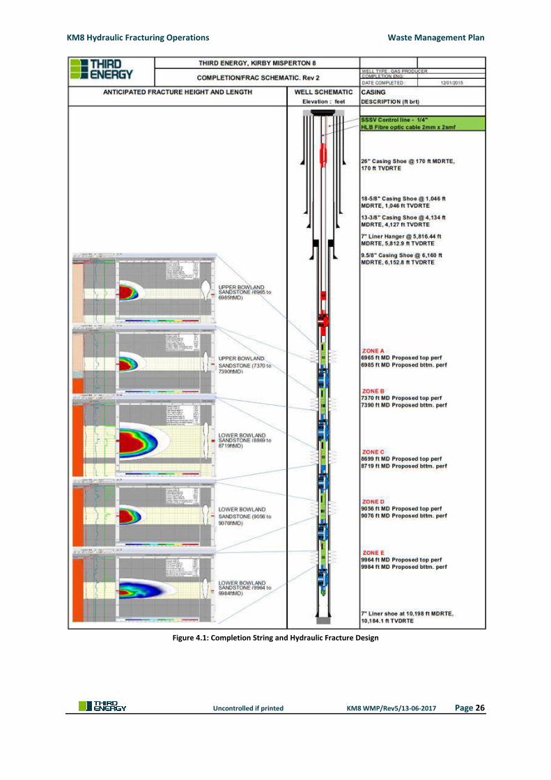
between the borehole and the formation. The depths of the five zones are:
Zone A - 2,123m (6,965ft) to 2,129m (6,985ft)
Zone B – 2,247m (7,370ft) to 2,253m (7,390ft)
Zone C – 2,652m (8,699ft) to 2,658m (8,719ft)
Zone D – 2,760m (9,056ft) to 2,766m (9,076ft)
Zone E – 3,037m (9,964ft) to 3,043m (9,984ft)
Prior to perforating, the volume of brine which has been in the well following the drilling operation
will be displaced with fresh water. The intention is to utilise the Applicant’s existing underground
water pipeline, which ordinarily is used for the transportation of produced water from Knapton
KM8 Hydraulic Fracturing Operations Waste Management Plan
Uncontrolled if printed KM8 WMP/Rev5/13-06-2017 Page 22
Generating Station to the KM3 reinjection well, to provide water to the KMA wellsite. Mains water
will be pumped from Knapton Generating Station to the KMA wellsite via the existing pipeline, from
where it will be transferred into temporary storage tanks on site, negating the requirement for road
transportation. Approximately 94m3 of fresh water will displace (push) the brine to surface where it
will be transferred from the KM8 well to on site storage tanks for subsequent reuse as suspension
brine within the hydraulic fracturing stimulation operation or considered for use at one of Third
Energy’s other wellsite operations. In the event brine cannot be reused it will be transported off site
for treatment and disposal at an Environment Agency permitted waste treatment facility.
The criteria for determining whether wastes will be recycled or disposed of will be determined by
the receiving waste treatment facility upon receipt of the waste at the treatment facility. The waste
will be tested by the waste treatment facility, the results of which will determine the treatment
and/or disposal method to be used. Such treatment and/or disposal method will be in accordance
with the waste treatment facility’s environmental permits.
The perforating operation involves the use of shaped explosive charges, which are set within a
perforating gun assembly and orientated for individual requirements. Upon detonation from surface,
each shape charge produces a jet, which penetrates the casing and into the formation, providing a
direct communication between the formation and the wellbore. Perforating guns are designed to
minimise debris by reducing external burrs (steel edges) which form as the jet exits the casing.
The perforating operation, in particular the use of shaped explosive charges, is regulated by the
Police Authority and the Health and Safety Executive. For the purpose of this Waste Management
Plan, only the management of extraction waste associated with the perforating operation, as
detailed in Section 4.3.1.2, will be regulated by the Environment Agency.
Once the 178mm (7”) casing has been perforated, the fired perforating guns will be brought back to
surface.
4.3.1.2 Cleaning the Wellbore
A clean up assembly will be run into the well and will scrape and remove any debris from the
perforations. Fresh water will be circulated down the workstring during the wellbore cleaning
operation and will circulate out the debris. The debris, consisting of small steel scrapings, will be
separated from the fluid at surface using a conventional shale shaker and circulating tank. The shale
shaker will capture any debris from the circulated fluid and divert them to a cuttings skip and the
produced water stored within an enclosed horizontal fluid tank for subsequent removal from site for
offsite recycling and/or disposal at an Environment Agency permitted waste treatment facility. The
waste will be tested by the waste treatment facility, the results of which will determine the
treatment and/or disposal method to be used. Such treatment and/or disposal method will be in
accordance with the waste treatment facility’s environmental permits.
4.3.1.3 Run Completion
Once the borehole has been cleaned and any perforating debris removed, a 114.3mm (4 ½”)
completion string will be run into the borehole. The completion string will consist of a number of
KM8 Hydraulic Fracturing Operations Waste Management Plan
Uncontrolled if printed KM8 WMP/Rev5/13-06-2017 Page 23
completion packers attached to a 114.3mm (4 ½”) tubing string, suitably spaced to provide individual
isolation of the five zones being hydraulically fractured. A sliding sleeve will be positioned between
each set of completion packers, which can be opened using wireline or coil tubing to allow fluid to
be pumped into each zone.
The completion string is engineered such to provide integrated down hole safety barriers and plug
profiles tied back to the surface wellhead, with a production hanger system connected to the 4 ½”
completion string. A series of valves will be installed on top of the wellhead to provide additional
safety barriers to the wellbore. Once installed and in advance of the hydraulic fracturing operation,
the completion string and wellhead will be pressure tested to confirm integrity. The pressure test
will be undertaken by shutting in the well and pressuring up the casing and wellhead to a
predetermined level to ensure subsequent pressures associated with the hydraulic fracturing
operation can be contained. A schematic of the completion string is shown in Figure 4.1, within
Section 4.3.2.
The workover operation is anticipated to take two weeks to complete, during which time the
operation will be undertaken 24 hrs per day.
Following installation and testing of the completion string, the workover rig will be de-mobilised
from the KMA wellsite.
4.3.2 Hydraulic Fracture Stimulation/Well Test
Third Energy has been issued with PL 080, which places a number of obligations on the Operator
(Third Energy) to submit information to DECC. In accordance with the requirements of its petroleum
licence, Third Energy is required to submit a Hydraulic Fracture Plan to DECC for approval. Once
approval is obtained, Third Energy must then undertake the hydraulic fracturing operation in
accordance with the approved plan.
Once the workover rig has been de-mobilised from the KMA wellsite, the hydraulic fracturing
equipment, coil tubing unit, wireline unit and well testing equipment will be rigged up and
commissioned. It is anticipated that some of the equipment required for the hydraulic fracture
stimulation will be delivered to site either before or during the workover phase and that the
remainder will be installed within the first two weeks of the hydraulic fracture phase, reducing the
number of peak traffic movements.
Each discrete zone will be hydraulically stimulated in turn, starting from Zone E at the bottom by
fully opening the sliding sleeve using wireline or coiled tubing and pumping the designed stimulation
treatment for that particular interval down the wellbore, through the perforated interval and into
the targeted formation.
The proppant chosen for the hydraulic fracturing operation is a chemically and physically inert
ceramic based product, specifically Carbo NRT. The use of such proppant compliments other
methods of monitoring fracture height growth to be used, as set out within the Hydraulic Fracture
Plan, by way of a Non-Radioactive Tracer (NRT), which can be detected by using standard oilfield
logging tools.
KM8 Hydraulic Fracturing Operations Waste Management Plan
Uncontrolled if printed KM8 WMP/Rev5/13-06-2017 Page 24
The ceramic proppant contains the non-radioactive tracer known as Gadolinium oxide which is a fine
powder contained within the ceramic proppant. Gadolinium is a rare earth metal that is a member
of the lanthanide group of chemicals and is used within the offshore oil and gas industry. Other uses
for Gadolinium and its compounds include use within glass, optic and ceramic applications and a
contrasting agent for Magnetic Resonance Imaging (MRI).
The proppant that is manufactured with the proprietary tracer uniformly distributed throughout
each proppant grain. This assures consistent distribution of the tracer throughout the near-wellbore
fracture zone, enabling more accurate measurement of proppant coverage and propped fracture
height. As the tracer is integral to the proppant matrix it cannot be dissolved or washed away.
A summary of its toxicology and ecotoxicology properties and its use as a low-level additive for
ceramic proppants for NRT applications has been provided within Appendix 5 of this Waste
Management Plan.
4.3.2.1 Hydraulic Fracture Treatment and Fluids
The hydraulic fracture treatment will be conducted during daylight hours only, however, preparation
times, including rigging up and rigging down the equipment, extends the overall duration of the
hydraulic fracturing and well test phase to approximately six (6) weeks. It involves pumping a water-
based hydraulic fracturing fluid at a sufficient pressure enabling the pre-existing slim fractures to be
opened up and improve the flow characteristics of the well. The exact proportion of the hydraulic
fracture fluid varies per treatment due to geological differences within the formation being
fractured. A full disclosure of the fracture treatment fluid, including a breakdown of each
component and its quantity is provided within Appendix 5. The components of the hydraulic fracture
fluid have been selected based on their non-hazardous to groundwater properties and have been
approved for use by the Environment Agency. The components of the hydraulic fracture fluid are
commonly used substances and can be found within most households, such as food and toiletries.
The KM8 hydraulic fracturing operation is proposing to hydraulically fracture five (5) discrete zones,
with an overall water requirement, including contingencies, of circa 4,000m3. In order to reduce the
impact of traffic and transport from the KM8 hydraulic fracturing operation, the intention is to utilise
the Applicant’s existing underground water pipeline, which ordinarily is used for the transportation
of produced water from Knapton Generating Station to the KM3 reinjection well. Mains water will
be pumped from Knapton Generating Station to the KMA wellsite via the existing pipeline, from
where it will be transferred into temporary storage tanks on site (roadable tanks), negating the
requirement for road transportation.
In order to ensure that the mains water being transported by the existing pipeline to the KMA
wellsite remains of the same quality when reaching the KMA wellsite, the existing pipeline will be
purged clean. A sample of mains water taken at the Knapton Generating Station will be analysed and
compared with a sample of mains water received at the KMA wellsite. If the samples are not
consistent further purging of the pipeline will be required. Only when sample taken at the Knapton
Generating Station and the receiving sample taken at the KMA wellsite are consistent will the water
from the pipeline be permitted for use.
KM8 Hydraulic Fracturing Operations Waste Management Plan
Uncontrolled if printed KM8 WMP/Rev5/13-06-2017 Page 25
Biofilms and bacterial growth are detrimental to oil and gas wells, insofar as they cause corrosion of
iron and steel as well as degradation of fluid additives used to enhance oil and gas production.
Historically, biocides were used in the treatment of aerobic and anaerobic bacteria. UV treatment
eliminates the requirement for biocides.
All fluids going into the well will be subject to UV treatment. UV treatment generates no waste.
Prior to each hydraulic fracture treatment being undertaken a number of initial fracture tests,
anticipated to be circa three (3) tests per zone being stimulated, will be carried out on the formation
to determine several important parameters e.g. the yield point, breakdown pressure, and
propagation pressure. The test involves the pumping of a small volume of fracture fluid without
proppant into the well under pressure, between a surface pressure range of circa 6,000psi to
7,000psi with an indicative fluid pumping rate of circa 4.8m3 (30bbls) to 8m3 (50bbls) per minute.
Once the test is complete, the data is used to determine the parameters for the main hydraulic
fracture treatment.
The main hydraulic fracture treatment will be conducted and will be based on the information
obtained during the initial fracture test, including surface pressures and fluid pumping rates. The
fracture treatment itself is not a long duration operation, expected to be approximately five hours in
total per treatment.
During the initial fracture test and main fracture treatments the operation will be monitored for
seismicity, adopting a ‘traffic light system’. The traffic light system provides for real-time monitoring
of seismicity and gives clear indication when a seismic event is imminent, allowing the Operator to
depressurise the fluid, thus drastically reducing or eliminating the potential seismic event. The traffic
light system forms part of a Hydraulic Fracture Plan, which is required to be submitted and approved
by DECC in advance of the operation commencing.
Once the hydraulic fracture fluid has been pumped, coil tubing will be run back down the wellbore to
the stimulated zone in order to circulate out any residual hydraulic fracture treatment from the
wellbore. The residual treatment will circulate to surface and be diverted from the KM8 well via the
well test separator and flowback treatment units to storage tanks on site for subsequent reuse.
A coil tubing drillable bridge plug will then be run and set above the opened sliding sleeve,
effectively isolating Zone E. Each stage will be similar in sequence to the first and will consist of fully
opening the sliding sleeve using wireline or coil tubing and pumping stimulation fluids. Figure 4.1
below shows the proposed hydraulic fracture completion design for all five zones.
KM8 Hydraulic Fracturing Operations Waste Management Plan
Uncontrolled if printed KM8 WMP/Rev5/13-06-2017 Page 26
Figure 4.1: Completion String and Hydraulic Fracture Design
KM8 Hydraulic Fracturing Operations Waste Management Plan
Uncontrolled if printed KM8 WMP/Rev5/13-06-2017 Page 27
4.3.2.2 Flowback Water Treatment, Reuse and Disposal
A percentage of the hydraulic fracture fluid used in each of the five (5) fracture treatments will be
returned to surface (flowback water) via the well test separator and treated making it suitable for
reuse in the next zone being hydraulically stimulated. The percentage returned is anticipated to be
circa 30% with the maximum of 50% having been recorded in previous hydraulic fracturing
operations. Treatment will consist of electrocoagulation, the process of which is described in detail
below. Treating the flowback water in this manner is consistent with Article 5 (2)(a)(i) of the Mining
Waste Directive 2006/21/EC by reducing the volume of waste needing to be transported offsite for
treatment and/or disposal and reduces water requirement for the subsequent zones being
hydraulically fractured. The criteria for determining whether the flowback water will be treated and
reused in subsequent hydraulic fracture treatments depends very much on actual flowback rates
encountered post hydraulic fracture treatment. If flowback rates are slow, the time required to
accumulate sufficient flowback fluid for treatment and reuse will increase significantly, extending
the overall duration of hydraulic fracturing operation.
In an attempt to reduce the duration and impact of the operation, all flowback water may be
diverted directly to storage tanks on site, where it will be held for subsequent offsite treatment
and/or disposal at an Environment Agency permitted waste treatment facility. The waste will be
tested by the waste treatment facility, the results of which will determine the treatment and/or
disposal method to be used. Such treatment and/or disposal method will be in accordance with the
waste treatment facility’s environmental permits.
A total of 1,330m3 of water storage will be available on site throughout the KM8 hydraulic fracturing
operation, which is sufficient to undertake the largest fracture treatment, Zone E, which is 1,250 m3.
The anticipated flowback is between 30% (399m3) and 50% (665m3). In the unlikely event that >50%
of flowback water is returned to surface, sufficient fluid storage is available.
Electrocoagulation Treatment
Flowback water passes through electrocoagulation cells, within which an anode and a cathode are
housed. The anode releases positively charged ions, which bind onto the negatively charged colloidal
particles in the water resulting in coagulation. Simultaneously, gas bubbles, produced at the
cathode, attach to the coagulation matter causing it to float to surface where it is removed by a
surface skimmer. Heavier coagulants sink to the bottom leaving clear water suitable for the
subsequent hydraulic fracture treatments.
The waste generated by electrocoagulation treatment is a non-hazardous solid waste, which will be
transported off site for disposal at an Environment Agency approved waste treatment facility.
A specification sheet detailing the electrocoagulation process is provided as Appendix 6.
KM8 Hydraulic Fracturing Operations Waste Management Plan
Uncontrolled if printed KM8 WMP/Rev5/13-06-2017 Page 28
Disposal
On completion of the fifth hydraulic fracture treatment, flowback water returning to surface is
considered a waste. It will be diverted from the KM8 well to storage tanks on site, for disposal at an
Environment Agency permitted waste treatment facility.
Naturally Occurring Radioactive Material (NORM)
Flowback water has the potential to contain low levels of Naturally Occurring Radioactive Material
(NORM), which predominantly relate to radioisotopes of radium (and associated progeny), which
find their way into the water due to their chemical solubility. Elevated concentrations of radium-226
and radium-228 progeny may also be present due to dissolved Rn-222 (radon) and, to a lesser
extent, Rn-220 (thoron) gas. Samples of flowback water shall be sent to a laboratory holding the
appropriate accreditations for radionuclide analysis. A successful clean-up and re-use of the
flowback water would result in the maximum anticipated volume of flowback water at surface being
approximately 450m3. Available storage of flowback water on site is 1,330m3 and therefore sufficient
to accommodate turnaround times associated with the analytical techniques required.
The management of NORM waste is the subject of a BAT assessment, which is provided as Appendix
7.
4.3.2.3 Retained Fluid within the Formation
The remaining 50% to 70% of hydraulic fracturing fluid will be retained within the formation, having
been absorbed on the charged, high surface area clays within the formation. None of the
constituents used within the hydraulic fracturing fluid are classified as hazardous under Directive
91/689/EEC nor classified as dangerous under Directive 67/548/EEC or Directive 1999/45/EC,
therefore, the formation within which the fluid is retained is expected to be classified by the
Environment Agency as a Non-Hazardous Mining Waste Facility, the extent of which will be
determined through microseismic fracture growth monitoring, providing evidence of the height and
distance of each hydraulic fracture growth. Table 4.2 within Section 4.4.2 Mining Waste operation
and Mining Waste Facility sets out the classification of waste streams associated with the KM8
hydraulic fracturing operation, including hydraulic fracture fluid. Waste management arrangements
for each waste stream, including hydraulic fracture fluid, in detailed within Section 5.3 of this Waste
Management Plan.
An indication of the areal extent of the Non-Hazardous Mining Waste Facility for the hydraulic
fracture treatment is included within document TE-EPRA-KM8-HFS-SP-004 and is based on the
maximum anticipated fracture length (Zone E), which is approximately 378m in length and 133m in
height. The base of the KM8 well is approximately 54m offset southeast of the surface location,
which, for clarity, is the top of the borehole within the KMA wellsite. The maximum anticipated
fracture lengths of Zones A to D are much less linear distance than that of Zone E, well within the
areal extent indicated within document TE-EPRA-KM8-HFS-SP-004.
Micro seismic fracture growth monitoring will be undertaken during the hydraulic fracturing
stimulation. Using proprietary software, preliminary forward modelling will be performed to
KM8 Hydraulic Fracturing Operations Waste Management Plan
Uncontrolled if printed KM8 WMP/Rev5/13-06-2017 Page 29
estimate what size of microseismic magnitude could be detected at different depths and what type
of location uncertainty would be associated with the respective events. Additional formation
velocity information will allow for a more accurate velocity model to be used in the forward
modelling and during the hydraulic fracturing operation.
A continuous digital recording of microseismic events will be undertaken during the hydraulic
fracturing operation. The system scans the data records for microseismic events using an advanced
detection algorithm measuring amongst other things amplitudes, frequency and signal correlation.
Event records will then be screened, edited (picked) and processed by a specialized and experienced
Microseismic Geophysicist using proprietary data management software within the data acquisition
unit situated on the KM8 wellsite. The processing of this data will be used to confirm event locations,
which in turn indicates the extent of the non-hazardous mining waste facility.
In order to determine what is considered Best Available Technique (BAT) for the disposal of retained
hydraulic fracture fluid, Third Energy has considered a number of alternative techniques.
The options considered as part of the BAT assessment include:
Recovery of all hydraulic fracture fluid over prolonged flowback periods during gas
production;
Increased recover of hydraulic fracture fluid using artificial lifting (submersible pumps);
Recover of hydraulic fracture fluid by excavation; and
Retention of hydraulic fracture fluid within the formation being stimulated.
The BAT assessment identified that both the prolonged flowback periods and artificial lift are
unlikely to result in a 100% recovery of hydraulic fracture fluid from the formation.
Recover by excavation is not considered feasible due to the depth of formation within which the
hydraulic fracture fluid is retained. Such methods of excavation would have a significant
environmental impact. This would involve the development of a mineshaft considerably wider than
the original KM8 borehole to a depth of circa 3,048m, sufficiently large enough to accommodate
structural supports for safety against collapse and of entry of necessary personnel, machinery and
supplies.
The development of a mine would create significant extractive waste, the volume of which would far
exceed the volume of waste the development seeks to retrieve from the target formation. This
option offers no environmental benefit and would cause significant local amenity impacts and
disruption to the local community. Economically, the development of a mine would render the
exploration and subsequent production of natural gas from the Bowland formation unviable.
As it is not feasible to retrieve 100% flowback, either by a prolonged flowback period or by artificial
lift and the removal of hydraulic fracture fluid by excavation is not feasible, retention within the
formation is considered BAT. The alternative options are unrealistic and/or theoretical in nature.
Injected non-hazardous hydraulic fracturing fluid, retained at depth does not present a credible
environmental risk.
KM8 Hydraulic Fracturing Operations Waste Management Plan
Uncontrolled if printed KM8 WMP/Rev5/13-06-2017 Page 30
Proppant retained within the formation prevents the fractures from closing and provides the
permeability for natural gas to flow. As the proppant fulfils a purpose, it is not considered a waste.
4.3.2.4 Coil Tubing Bridge Plug Milling
Once all five (5) zones have been hydraulically stimulated and cleaned out, the hydraulic fracturing
equipment will be de-mobilised from site.
Coil tubing will be run into the borehole with a suitable drilling bit and will proceed to drill out each
of the bridge plugs in turn, starting with the top plug. Fluid will be circulated down the coil tubing
during the drilling operation and will circulate out the cuttings generated from the drilling action.
The cuttings will be separated from the fluid at surface using a conventional shale shaker and
circulating tank. The shale shaker will capture any cuttings from the drilling and divert them to a
cuttings skip for subsequent removal from site for offsite recycling and/or disposal at an
Environment Agency permitted waste treatment facility, similar to the practices used during the
drilling of the KM8 well. The waste will be tested by the waste treatment facility, the results of which
will determine the treatment and/or disposal method to be used. Such treatment and/or disposal
method will be in accordance with the waste treatment facility’s environmental permits.
Once all of the bridge plugs have been milled, the KM8 well is ready to be flow tested.
4.3.2.5 Well Test
Well testing equipment will be mobilised to site during the first week of hydraulic fracturing phase,
rigged up and commissioned. Well testing equipment will consist of a choke manifold, a solids
removal system, a test separator, which separates any gas from fluids and fluid storage tanks.
Once all of the bridge plugs have been milled, the well is ready to be flow tested. Coil tubing will first
be run into the base of well. Nitrogen will then be pumped through and out of the coil tubing
positioned at the base of the well. The nitrogen will then flow to surface displacing (pushing) the
fluid in the well back to surface. This process reduces the hydrostatic weight of the fluid column in
the wellbore, which in turn allows the gas to flow to surface. Nitrogen is classified as inert and, as
such, considered a closed loop system, having first been extracted from the atmosphere during its
manufacturing process and subsequently released to atmosphere during the natural gas combustion
process within the gas turbine at the Knapton Generating Station. No nitrogen will remain in the
formation.
The volume of nitrogen pumped into the well to displace (pushing) the fluids in the well will be
closely monitored. To minimise the amount of nitrogen used, calculations will be used to determine
the amount required to displace the fluids before gas reaches surface. The volume of nitrogen
required to displace the well fluid is low and will comingle with the gas. The volume of nitrogen
within the gas is not considered sufficient to compromise the composition of the gas feeding the GE
LM6000 gas turbine at the Knapton Generating Station. Table 4.1 below provides the gas
composition, based on a detailed evaluation of the log and core data, which identifies Nitrogen as a
component of the gas, ranging from 0.41% to 10.2% with a 4.13% average over the five (5) zones
being hydraulically fractured.
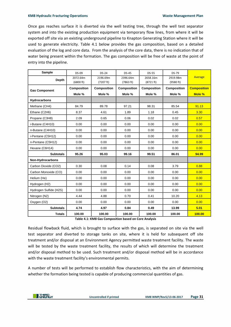
KM8 Hydraulic Fracturing Operations Waste Management Plan
Uncontrolled if printed KM8 WMP/Rev5/13-06-2017 Page 31
Once gas reaches surface it is diverted via the well testing tree, through the well test separator
system and into the existing production equipment via temporary flow lines, from where it will be
exported off site via an existing underground pipeline to Knapton Generating Station where it will be
used to generate electricity. Table 4.1 below provides the gas composition, based on a detailed
evaluation of the log and core data. From the analysis of the core data, there is no indication that of
water being present within the formation. The gas composition will be free of waste at the point of
entry into the pipeline.
Sample DS-09 DS-24 DS-45 DS-55 DS-79
Average Depth
2072.64m
(6800 ft)
2196.69m
(7207 ft)
2396.64m
(7863 ft)
2658.16m
(8721 ft)
2919.98m
(9580 ft)
Gas Component Composition Composition Composition Composition Composition Composition
Mole % Mole % Mole % Mole % Mole % Mole %
Hydrocarbons
Methane (CH4) 84.79 89.78 97.21 98.31 85.54 91.13
Ethane (C2H6) 8.37 4.61 1.89 1.18 0.45 3.30
Propane (C3H8) 2.09 0.65 0.06 0.02 0.02 0.57
i-Butane (C4H10) 0.00 0.00 0.00 0.00 0.00 0.00
n-Butane (C4H10) 0.00 0.00 0.00 0.00 0.00 0.00
i-Pentane (C5H12) 0.00 0.00 0.00 0.00 0.00 0.00
n-Pentane (C5H12) 0.00 0.00 0.00 0.00 0.00 0.00
Hexane (C6H14) 0.00 0.00 0.00 0.00 0.00 0.00
Subtotals 95.26 95.03 99.16 99.51 86.01 94.99
Non-Hydrocarbons
Carbon Dioxide (CO2) 0.30 0.08 0.14 0.08 3.79 0.88
Carbon Monoxide (CO) 0.00 0.00 0.00 0.00 0.00 0.00
Helium (He) 0.00 0.00 0.00 0.00 0.00 0.00
Hydrogen (H2) 0.00 0.00 0.00 0.00 0.00 0.00
Hydrogen Sulfide (H2S) 0.00 0.00 0.00 0.00 0.00 0.00
Nitrogen (N2) 4.44 4.88 0.70 0.41 10.20 4.13
Oxygen (O2) 0.00 0.00 0.00 0.00 0.00 0.00
Subtotals 4.74 4.97 0.84 0.49 13.99 5.01
Totals 100.00 100.00 100.00 100.00 100.00 100.00
Table 4.1: KM8 Gas Composition based on Core Analysis
Residual flowback fluid, which is brought to surface with the gas, is separated on site via the well
test separator and diverted to storage tanks on site, where it is held for subsequent off site
treatment and/or disposal at an Environment Agency permitted waste treatment facility. The waste
will be tested by the waste treatment facility, the results of which will determine the treatment
and/or disposal method to be used. Such treatment and/or disposal method will be in accordance
with the waste treatment facility’s environmental permits.
A number of tests will be performed to establish flow characteristics, with the aim of determining
whether the formation being tested is capable of producing commercial quantities of gas.
KM8 Hydraulic Fracturing Operations Waste Management Plan
Uncontrolled if printed KM8 WMP/Rev5/13-06-2017 Page 32
4.3.3 Production Test
Once the hydraulic fracturing stimulation is complete all five (5) zones will be flowed to determine
the deliverability of the well over a period of time. Wireline tools may be run into the well during the
production test to see which zones are most prolific.
This phase of the operations will require minimal equipment to be brought onsite, primarily
consisting of a high pressure flowline and some temporary pipework connecting the KM8 well with
the existing production equipment on site, which will be installed and operated for up to ninety (90)
days.
As with the current arrangement on site for gas production, gas will be flowed to the surface and
into the existing production facilities, from where it will be transported via pipeline to the Knapton
Generating Station for subsequent generation of electricity.
The production test operation will be performed 24 hours/day.
Based on a detailed evaluation of the log and core data it is anticipated that any gas produced from
the Bowland formation will be dry. Whilst very unlikely, if formation water is produced with the
natural gas, it will be removed as part of the routine production activity, which includes phase
separation and liquid storage on site for subsequent off site treatment and/or disposal at an
Environment Agency permitted waste treatment facility. The waste will be tested by the waste
treatment facility, the results of which will determine the treatment and/or disposal method to be
used. Such treatment and/or disposal method will be in accordance with the waste treatment
facility’s environmental permits.
4.3.4 Production
On completion of the well testing phase and/or the production test phase, Third Energy will make a
decision as to whether the prospect is commercially viable. If a successful production test is achieved
the KM8 well be permanently hooked up to the existing production equipment on site.
To enable the permanent hook-up of the KM8 well to the existing production equipment on site,
only minor additional equipment will be required, consisting of permanent high pressure flowline,
pipe supports and minor groundworks.
Once permanent hook-up is complete and commissioned, production of natural gas will commence.
Natural gas will flow to surface under pressure and pass through the production equipment onsite.
Produced gas is transferred to Knapton Generating Station via pipeline where it will be used to
generate electricity, which in turn is exported to the national grid.
Based on a detailed evaluation of the log and core data it is anticipated that any gas produced from
the Bowland formation will be dry. Whilst very unlikely, if formation water is produced with the
natural gas, it will be removed as part of the routine production activity, which includes phase
separation and liquid storage on site for subsequent off site treatment and/or disposal at an
Environment Agency permitted waste treatment facility. The waste will be tested by the waste
treatment facility, the results of which will determine the treatment and/or disposal method to be
KM8 Hydraulic Fracturing Operations Waste Management Plan
Uncontrolled if printed KM8 WMP/Rev5/13-06-2017 Page 33
used. Such treatment and/or disposal method will be in accordance with the waste treatment
facility’s environmental permits.
4.3.5 Existing KM7 Well
In 1985, the then current owners of the wellsite, Taylor Woodrow Energy, drilled the first well from
the Kirby Misperton 1 wellsite, KM1. The well was successful in proving commercial quantities of
natural gas in place and was subsequently completed as a Namurian gas producer. In 2012, the well
was re-entered and sidetracked. KM7, but was unsuccessful in producing gas. The well has since
been suspended pending further evaluation of the Kirby Misperton Gas Field
For clarity, there is no direct connection between the existing KM7 well (flowline) and the KM8 well.
The original KM1 well was abandoned in accordance with Oil & Gas UK guidelines immediately
below the point at which the well was sidetracked.
A schematic showing the proximity of KM7 well and KM3 well to the KM8 well is provided within
Figure 4.2.
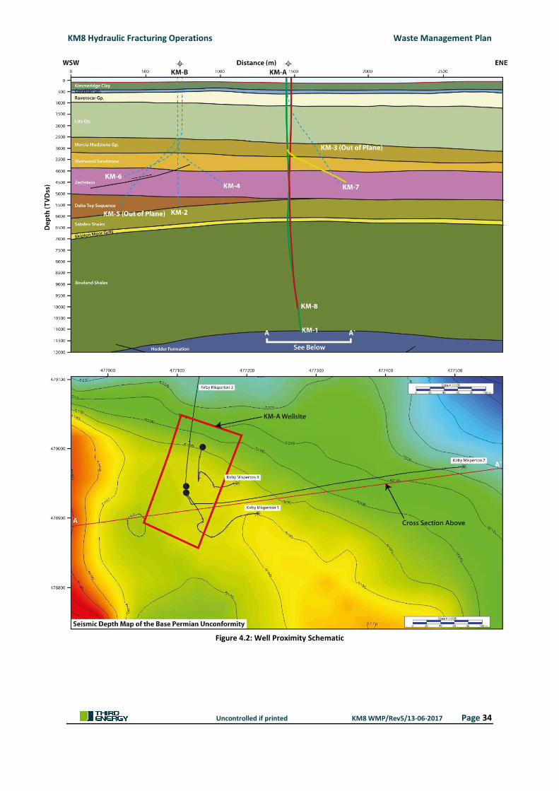
KM8 Hydraulic Fracturing Operations Waste Management Plan
Uncontrolled if printed KM8 WMP/Rev5/13-06-2017 Page 34
Figure 4.2: Well Proximity Schematic
KM8 Hydraulic Fracturing Operations Waste Management Plan
Uncontrolled if printed KM8 WMP/Rev5/13-06-2017 Page 35
4.3.6 Existing KM3 Produced Water Reinjection Well
In 1987, the then current owners of the wellsite, Kelt UK Limited, drilled a second well from the Kirby
Misperton 1 wellsite, KM3. The well was subsequently completed as a produced water reinjection
well in to the Kirkham Abbey formation and is permitted under a Consent to Discharge (Ref:
NPSWQD001330) issued 15th February 2010 to discharge Trade Effluent comprising formation water
and gas condensate from The gas extraction wells and Knapton Generating station [Ref.17].
For the purpose of absolute clarity, the KM8 hydraulic fracturing operation, including the well test,
production test and subsequent production, does not contemplate nor propose the use of the
existing KM3 produced water reinjection well to dispose of flowback water. There is no physical
connection (flowline) between the KM8 well and the KM3 well.
Based on a detailed evaluation of the log and core data it is anticipated that any gas produced from
the Bowland formation will be dry. Whilst very unlikely, if formation water is produced with the
natural gas, it will be removed as part of the routine production activity, which includes phase
separation and liquid storage on site for subsequent off site treatment and/or disposal at an
Environment Agency permitted waste treatment facility. The waste will be tested by the waste
treatment facility, the results of which will determine the treatment and/or disposal method to be
used. Such treatment and/or disposal method will be in accordance with the waste treatment
facility’s environmental permits.
The onsite removal of any moisture or formation water during the KM8 well test, production test
and subsequent production will ensure that no waste (flowback water) enters the pipeline, thus
eliminating the commingling of formation water and gas condensate produced from other producing
wells, which ultimately is reinjected in to the Kirkham Abbey formation via the KM3 well.
4.3.7 Existing Production Equipment
To facilitate the production of natural gas at the wellsite, production equipment consisting of
corrosion inhibitor and glycol tanks, separator module, pig launcher and control room has been
installed. The KMA wellsite also accommodates the separator module for the Pickering 1 well. The
production equipment is skid mounted, individually bunded and sits upon dedicated concrete bases.
The production equipment has a number of emergency vent points throughout the process. These
vent points, together with anticipated flow rates, gas composition, leak rates and potential fugitive
gas from flowback water has been assessed and an emissions dispersion model established using the
ADMS 5 model. The emissions dispersion modelling is included within the Air Quality Impact
Assessment included as Appendix 8.
4.3.8 Acceptable Gas Composition (Knapton Generating Station)
Natural gas produced from the KM8 well will be transferred to Knapton Generating Station via
pipeline where it will be used to generate electricity by way of a gas powered turbine. The gas
powered turbine (GE LM6000) is capable of operating within a range of gas compositions. In the
unlikely event, however, that the natural gas produced from the KM8 well or likewise, any other well
within the Ryedale Gas Fields, is outside of the operating range of gas composition for the GE
KM8 Hydraulic Fracturing Operations Waste Management Plan
Uncontrolled if printed KM8 WMP/Rev5/13-06-2017 Page 36
LM6000 turbine, production will be suspended, the responsible well identified and production from
that well suspended.
Based on a detailed evaluation of the log and core data it is anticipated that any gas produced from
the Bowland formation will be within the acceptable gas composition range of the GE LM6000
turbine.
4.4 CLASSIFICATION OF OPERATION
A review of the proposed KM8 hydraulic fracturing operations against applicable environmental
legislation has identified the following classifications as being applicable to the wellsite.
4.4.1 A Groundwater Activity
The Environmental Permitting (England & Wales) Regulations 2016, which transposes the
requirements of the Water Framework Directive 2000/60/EC [Ref.18], requires groundwater
activities to be authorised. A groundwater activity is defined in schedule 22 Paragraph 3 (1) (c) any
other discharge that might lead to the direct or indirect input of a pollutant to groundwater.
Although the risk to groundwater is very low due to the way in which Third Energy has constructed
the KM8 borehole and that only non-hazardous constituents will be used within the hydraulic
fracturing fluid, Third Energy is taking a precautionary approach to the KM8 hydraulic fracturing
operations by applying for a groundwater activity permit.
For the purpose of this Waste Management Plan, the KM8 exploratory operations are expected to
be classified by the Environment Agency as a groundwater activity, namely, any other discharge that
might lead to the direct or indirect input of a pollutant to groundwater.
4.4.2 Mining Waste Operation and Mining Waste Facility
The Environmental Permitting (England and Wales) Regulations 2016, which transposes the
requirements of the Mining Waste Directive 2006/21/EC, requires mining waste operations to be
authorised. A mining waste operation is defined in Schedule 20 paragraph 2 (1) of EPR 2016 as ‘the
management of extractive waste, whether or not involving, a mining waste facility.
For the purpose of this Waste Management Plan, the KM8 hydraulic fracturing operations are
classified as:
A Non-Hazardous Mining Waste Operation for the management of extraction waste,
whether or not involving a mining waste facility. Non-hazardous extractive waste will be
produced during the pre-stimulation workover, the electrocoagulation treatment of
flowback water, the flow back to surface of the hydraulic fracture treatment fluid following
the fifth hydraulic fracture treatment and residual flow back water during well testing
operations. A permit subject to the mining waste directive covers the management of
extracted waste and not the extraction process;
A Non-Hazardous Mining Waste Facility for the accumulation of hydraulic fracture fluid
which will not return to the surface and will remain within the formation being stimulated. A
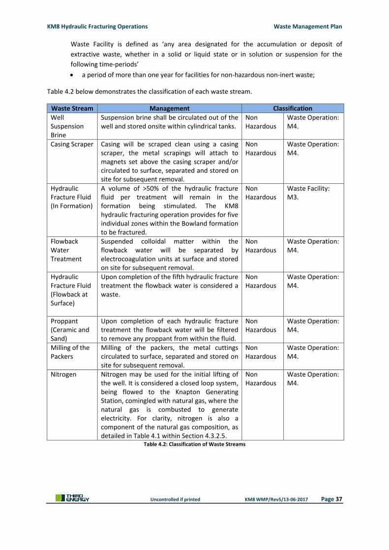
KM8 Hydraulic Fracturing Operations Waste Management Plan
Uncontrolled if printed KM8 WMP/Rev5/13-06-2017 Page 37
Waste Facility is defined as ‘any area designated for the accumulation or deposit of
extractive waste, whether in a solid or liquid state or in solution or suspension for the
following time-periods’
a period of more than one year for facilities for non-hazardous non-inert waste;
Table 4.2 below demonstrates the classification of each waste stream.
Waste Stream Management Classification
Well Suspension Brine
Suspension brine shall be circulated out of the well and stored onsite within cylindrical tanks.
Non Hazardous
Waste Operation: M4.
Casing Scraper Casing will be scraped clean using a casing scraper, the metal scrapings will attach to magnets set above the casing scraper and/or circulated to surface, separated and stored on site for subsequent removal.
Non Hazardous
Waste Operation: M4.
Hydraulic Fracture Fluid (In Formation)
A volume of >50% of the hydraulic fracture fluid per treatment will remain in the formation being stimulated. The KM8 hydraulic fracturing operation provides for five individual zones within the Bowland formation to be fractured.
Non Hazardous
Waste Facility: M3.
Flowback Water Treatment
Suspended colloidal matter within the flowback water will be separated by electrocoagulation units at surface and stored on site for subsequent removal.
Non Hazardous
Waste Operation: M4.
Hydraulic Fracture Fluid (Flowback at Surface)
Upon completion of the fifth hydraulic fracture treatment the flowback water is considered a waste.
Non Hazardous
Waste Operation: M4.
Proppant (Ceramic and Sand)
Upon completion of each hydraulic fracture treatment the flowback water will be filtered to remove any proppant from within the fluid.
Non Hazardous
Waste Operation: M4.
Milling of the Packers
Milling of the packers, the metal cuttings circulated to surface, separated and stored on site for subsequent removal.
Non Hazardous
Waste Operation: M4.
Nitrogen Nitrogen may be used for the initial lifting of the well. It is considered a closed loop system, being flowed to the Knapton Generating Station, comingled with natural gas, where the natural gas is combusted to generate electricity. For clarity, nitrogen is also a component of the natural gas composition, as detailed in Table 4.1 within Section 4.3.2.5.
Non Hazardous
Waste Operation: M4.
Table 4.2: Classification of Waste Streams
KM8 Hydraulic Fracturing Operations Waste Management Plan
Uncontrolled if printed KM8 WMP/Rev5/13-06-2017 Page 38
5. EXTRACTIVE AND NON-EXTRACTIVE WASTE MANAGEMENT
The following sections describe the various extractive and non-extractive wastes arising from the
KM8 hydraulic fracturing operation, their classification and anticipated quantities. This section also
describes the objectives of Third Energy of appropriately manage waste and how these objectives
are achieved through waste minimisation, methods of treatment and disposal.
5.1 OPERATOR WASTE OBJECTIVES
The Third Energy UK Gas Limited’s policy on waste Duty of Care, waste segregation, waste handling
and waste transfer are set out and based upon the Environmental Management System, Knapton
Generating Station Waste Management Plan.
The Site Waste Champion for the KMA wellsite will be the Third Energy HSE Supervisor who reports
directly to the Third Energy HSE Manager, who in turn reports to the Third Energy Operations
Director. In addition to his duties HSE duties, the Third Energy HSE Supervisor will:
Promote awareness of the Waste Management Plan;
Monitor and report on waste generation;
Monitor and enforce on waste segregation;
Monitor the effectiveness of the Waste Management Plan;
Form a good working relationship with the waste management contractor; and
Encourage suggestions for better waste management on site.
Article 5(2) of the Mining Waste Directive sets out the objective of the waste management plan.
(a) to prevent or reduce waste production and its harmfulness, in particular by considering:
(i) waste management in the design phase and in the choice of the method used for mineral
extraction and treatment;
(ii) the changes that the extractive waste may undergo in relation to an increase in surface area
and exposure to conditions above ground;
(iii) placing extractive waste back into the excavation void after extraction of the mineral, as far
as is technically and economically feasible and environmentally sound in accordance with
existing environmental standards at Community level and with the requirements of this
Directive where relevant;
(iv) putting topsoil back in place after the closure of the waste facility or, if this is not practically
feasible, reusing topsoil elsewhere;
(v) using less dangerous substances for the treatment of mineral resources;
(b) to encourage the recovery of extractive waste by means of recycling, reusing or reclaiming such
waste, where this is environmentally sound in accordance with existing environmental
standards at Community level and with the requirements of this Directive where relevant;
KM8 Hydraulic Fracturing Operations Waste Management Plan
Uncontrolled if printed KM8 WMP/Rev5/13-06-2017 Page 39
(c) to ensure short and long-term safe disposal of the extractive waste, in particular by considering,
during the design phase, management during the operation and after‐closure of a waste facility
and by choosing a design which:
(i) requires minimal and, if possible, ultimately no monitoring, control and management of the
closed waste facility;
(ii) prevents or at least minimises any long-term negative effects, for example attributable to
migration of airborne or aquatic pollutants from the waste facility; and
(iii) ensures the long-term geotechnical stability of any dams or heaps rising above the pre-
existing ground surface.
In accordance with Article 5(2)(i) of the Mining Waste Directive, two possible methods for the
management of flowback water were identified during the design phase of the KM8 hydraulic
fracturing operations.
The first method of flowback water management involves the treatment and reuse of flowback
water, which reduces the overall volume of waste water disposal off site. In doing so, however, it
introduces an additional waste stream, in the form of a post treatment sludge (85% water and 15%
suspended solids). This method is contingent on flowback rates encountered post hydraulic fracture
treatment. If flowback rates are slow, the time required to accumulate sufficient flowback fluid for
treatment and reuse will increase significantly, extended the overall duration of hydraulic fracturing
operations. In turn, this will increase the volume of other waste streams associated with the
operation.
The second method of flowback water management involves the offsite treatment and/or disposal
at an Environment Agency permitted waste treatment facility. This method of flowback water
management provides a degree of certainty over the duration of the operation and negates any risk
of having to extend the duration to allow for the treatment and reuse of flowback water. In turn, this
will negate an increase in the volume of other waste streams associated with the operation.
On that basis that both methods of flowback water management are intended to minimise overall
waste production, both methods can be considered as meeting the requirements of Article 5(2)(a) of
the Mining Waste Directive.
With reference to Article 5(2)(ii) of the Mining Waste Directive, extractive waste generated during
KM8 hydraulic fracturing operation does not undergo any changes in relation to surface area or
exposure to conditions above ground. It is the intention that all extractive waste generated during
the KM8 hydraulic fracturing operation will be temporarily stored on site for subsequent off site
treatment and/or disposal at an Environment Agency permitted waste treatment facility.
In the case of the KM8 hydraulic fracturing operation, the operation does not generate extraction
voids nor does current environmental legislation support the reinjection of flowback water from a
high volume hydraulic fracture operation. Article 5(2)(iii) of the Mining Waste Directive is, therefore,
not applicable to the KM8 hydraulic fracturing operation.
KM8 Hydraulic Fracturing Operations Waste Management Plan
Uncontrolled if printed KM8 WMP/Rev5/13-06-2017 Page 40
The KMA wellsite is subject to a closure plan upon cessation of natural gas production. The closure
plan will set out the details for wellsite restoration, including the replacement of topsoil currently
stored on site. The reuse of topsoil after closure accords with Article 5(2)(iv) of the Mining Waste
Directive.
With reference to Article 5(2)(v) of the Mining Waste Directive, only non-hazardous constituents will
be used within the hydraulic fracturing fluid. Each constituent not having previously been approved
by the Environment Agency, has been assessed using the Joint Agencies Groundwater Directive
Advisory Group (JAGDAG) assessment methodology. The assessment concluded that all constituents
assessed for use in the KM8 hydraulic fracturing operation are classified as non-hazardous to
groundwater. A copy of the JAGDAG substances assessment is provided within Appendix 4 of this
Waste Management Plan.
5.2 WASTE PREVENTION AND MINIMISATION
Third Energy and its specialist contractors follow Article 4 of the revised EU Waste Framework
Directive which is transposed within UK law through The Waste (England and Wales) Regulations
2011.
5.2.1 Waste Prevention
Every effort will be made to eliminate the waste produced at source. Control measures will include:
Avoiding packaged material where practicable;
Ordering correct quantities;
Avoiding damage by handling and storing correctly;
Using less materials in designs and manufacturing;
5.2.2 Preparing for Re-Use
Only dispose of waste which cannot economically or practically be re-used or recycled. Materials
such as drilling fluids can be readily re-used. Checking, cleaning, repairing and refurbishing or items
and spare parts for subsequent re-use.
5.2.3 Recycle
Waste is to be segregated onsite to allow for recycling off site. Additionally, materials that are
recycled shall be procured for use on site where practicable and where specification permits.
Turning waste into a substance or product including composting or for the treatment of soils subject
to quality protocols.
5.2.4 Other Recovery
Anaerobic digestion, incineration with energy recovery, gasification and pyrolysis which produce
energy (fuels, heat and power) and materials from waste, some backfilling.
KM8 Hydraulic Fracturing Operations Waste Management Plan
Uncontrolled if printed KM8 WMP/Rev5/13-06-2017 Page 41
5.2.5 Dispose
Waste that cannot be reused or recycled practicably shall be disposed of responsibly and in
compliance with Third Energy UK Gas Limited duty of care obligations. All waste shall be removed
from site by a licenced waste carrier to a licenced waste site.
5.3 WASTE DESCRIPTION AND MANAGEMENT ARRANGEMENTS
An assessment of the potential waste arising from the KM8 hydraulic fracturing operations has been
undertaken. The potential waste, together with its classification anticipated quantities, prevention,
minimisation, treatment and disposal is provided in this section.
For the purpose of information, storage tanks will be located at various positions on the KMA
wellsite. Storage tanks will be positioned on the southern and western boundaries of the KM1
wellsite extension. Storage tanks will also be placed on the northern section of the original KM1
wellsite, immediately south of the gabion wall, which separates the two sites. A site layout drawing,
showing the location of the storage tanks, together with the hydraulic fracturing equipment is
included within Appendix 9 of this Waste Management Plan.
The storage tanks will be fully sealed and hydrostatically tested following construction and routinely
tested as part of an ongoing maintenance system. Each storage tank is fitted with an emergency
relief vent, which under normal operating conditions is in the closed position. In the unlikely event
that the storage tanks should see a build-up of pressure, the pressure relief vent will open to release
the pressure.
Air quality monitoring, together with real-time gas detection, will be used to monitor fugitive
releases from storage tanks. Real-time gas detection is primarily used for occupational safety
monitoring, providing site personnel with early warning in the event of a gas release. Such
occupational safety monitoring will also provide early indication of a gas release, which may have
the potential to impact on Air Quality Standards (AQS). The early warning will initiate emergency
actions on site to minimise and control the release.
All storage tanks and skips will be located upon an impermeable membrane. Storage tanks and skips
located within KM1 wellsite extension will utilise the existing HDPE impermeable membrane.
Storage tanks and skips located within the original Kirby Misperton 1 wellsite will be sited upon an
impermeable membrane with bunded walls.
Third Energy has assessed the potential waste streams arising from the KM8 hydraulic fracturing
operations and understands its responsibility to ensure that all waste streams are characterised and
carried out to ensure that the waste produced is treated or disposed of appropriately. All waste
arising from the KM8 hydraulic fracturing operations are accepted by a number of permitted waste
treatment and/or disposal facilities in the UK.
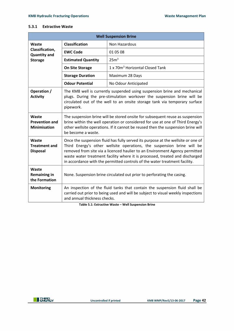
KM8 Hydraulic Fracturing Operations Waste Management Plan
Uncontrolled if printed KM8 WMP/Rev5/13-06-2017 Page 42
5.3.1 Extractive Waste
Well Suspension Brine
Waste Classification, Quantity and Storage
Classification Non Hazardous
EWC Code 01 05 08
Estimated Quantity 25m3
On Site Storage 1 x 70m3 Horizontal Closed Tank
Storage Duration Maximum 28 Days
Odour Potential No Odour Anticipated
Operation / Activity
The KM8 well is currently suspended using suspension brine and mechanical plugs. During the pre-stimulation workover the suspension brine will be circulated out of the well to an onsite storage tank via temporary surface pipework.
Waste Prevention and Minimisation
The suspension brine will be stored onsite for subsequent reuse as suspension brine within the well operation or considered for use at one of Third Energy’s other wellsite operations. If it cannot be reused then the suspension brine will be become a waste.
Waste Treatment and Disposal
Once the suspension fluid has fully served its purpose at the wellsite or one of Third Energy’s other wellsite operations, the suspension brine will be removed from site via a licenced haulier to an Environment Agency permitted waste water treatment facility where it is processed, treated and discharged in accordance with the permitted controls of the water treatment facility.
Waste Remaining in the Formation
None. Suspension brine circulated out prior to perforating the casing.
Monitoring An inspection of the fluid tanks that contain the suspension fluid shall be carried out prior to being used and will be subject to visual weekly inspections and annual thickness checks.
Table 5.1: Extractive Waste – Well Suspension Brine
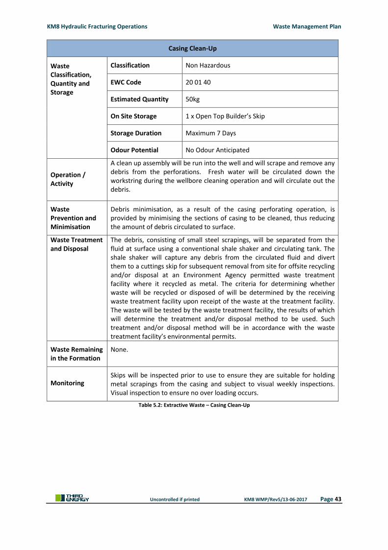
KM8 Hydraulic Fracturing Operations Waste Management Plan
Uncontrolled if printed KM8 WMP/Rev5/13-06-2017 Page 43
Casing Clean-Up
Waste Classification, Quantity and Storage
Classification Non Hazardous
EWC Code 20 01 40
Estimated Quantity 50kg
On Site Storage 1 x Open Top Builder’s Skip
Storage Duration Maximum 7 Days
Odour Potential No Odour Anticipated
Operation / Activity
A clean up assembly will be run into the well and will scrape and remove any debris from the perforations. Fresh water will be circulated down the workstring during the wellbore cleaning operation and will circulate out the debris.
Waste Prevention and Minimisation
Debris minimisation, as a result of the casing perforating operation, is provided by minimising the sections of casing to be cleaned, thus reducing the amount of debris circulated to surface.
Waste Treatment and Disposal
The debris, consisting of small steel scrapings, will be separated from the fluid at surface using a conventional shale shaker and circulating tank. The shale shaker will capture any debris from the circulated fluid and divert them to a cuttings skip for subsequent removal from site for offsite recycling and/or disposal at an Environment Agency permitted waste treatment facility where it recycled as metal. The criteria for determining whether waste will be recycled or disposed of will be determined by the receiving waste treatment facility upon receipt of the waste at the treatment facility. The waste will be tested by the waste treatment facility, the results of which will determine the treatment and/or disposal method to be used. Such treatment and/or disposal method will be in accordance with the waste treatment facility’s environmental permits.
Waste Remaining in the Formation
None.
Monitoring Skips will be inspected prior to use to ensure they are suitable for holding metal scrapings from the casing and subject to visual weekly inspections. Visual inspection to ensure no over loading occurs.
Table 5.2: Extractive Waste – Casing Clean-Up
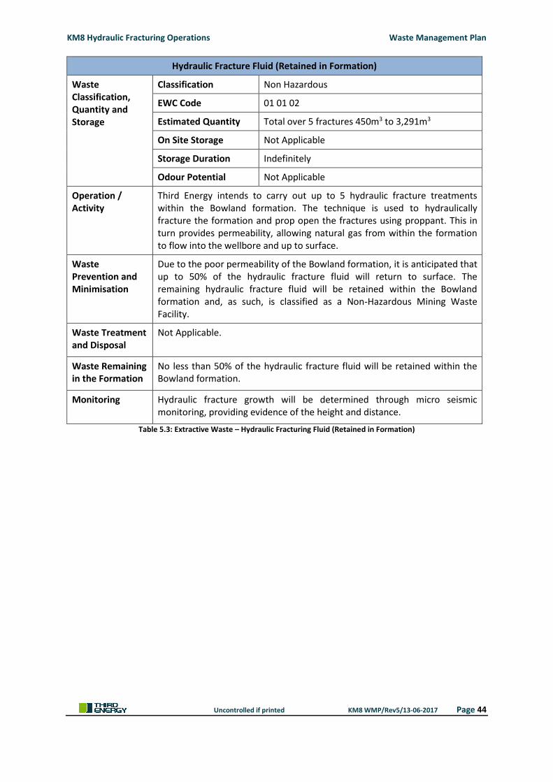
KM8 Hydraulic Fracturing Operations Waste Management Plan
Uncontrolled if printed KM8 WMP/Rev5/13-06-2017 Page 44
Hydraulic Fracture Fluid (Retained in Formation)
Waste Classification, Quantity and Storage
Classification Non Hazardous
EWC Code 01 01 02
Estimated Quantity Total over 5 fractures 450m3 to 3,291m3
On Site Storage Not Applicable
Storage Duration Indefinitely
Odour Potential Not Applicable
Operation / Activity
Third Energy intends to carry out up to 5 hydraulic fracture treatments within the Bowland formation. The technique is used to hydraulically fracture the formation and prop open the fractures using proppant. This in turn provides permeability, allowing natural gas from within the formation to flow into the wellbore and up to surface.
Waste Prevention and Minimisation
Due to the poor permeability of the Bowland formation, it is anticipated that up to 50% of the hydraulic fracture fluid will return to surface. The remaining hydraulic fracture fluid will be retained within the Bowland formation and, as such, is classified as a Non-Hazardous Mining Waste Facility.
Waste Treatment and Disposal
Not Applicable.
Waste Remaining in the Formation
No less than 50% of the hydraulic fracture fluid will be retained within the Bowland formation.
Monitoring Hydraulic fracture growth will be determined through micro seismic monitoring, providing evidence of the height and distance.
Table 5.3: Extractive Waste – Hydraulic Fracturing Fluid (Retained in Formation)
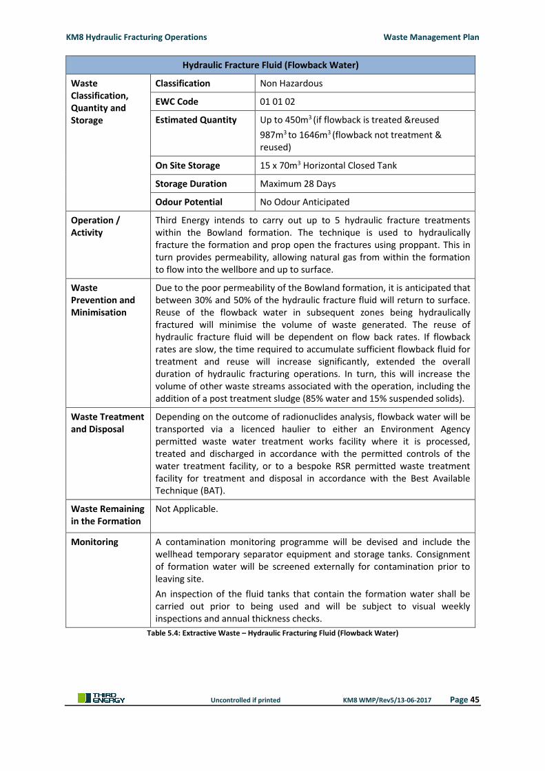
KM8 Hydraulic Fracturing Operations Waste Management Plan
Uncontrolled if printed KM8 WMP/Rev5/13-06-2017 Page 45
Hydraulic Fracture Fluid (Flowback Water)
Waste Classification, Quantity and Storage
Classification Non Hazardous
EWC Code 01 01 02
Estimated Quantity Up to 450m3 (if flowback is treated &reused
987m3 to 1646m3 (flowback not treatment & reused)
On Site Storage 15 x 70m3 Horizontal Closed Tank
Storage Duration Maximum 28 Days
Odour Potential No Odour Anticipated
Operation / Activity
Third Energy intends to carry out up to 5 hydraulic fracture treatments within the Bowland formation. The technique is used to hydraulically fracture the formation and prop open the fractures using proppant. This in turn provides permeability, allowing natural gas from within the formation to flow into the wellbore and up to surface.
Waste Prevention and Minimisation
Due to the poor permeability of the Bowland formation, it is anticipated that between 30% and 50% of the hydraulic fracture fluid will return to surface. Reuse of the flowback water in subsequent zones being hydraulically fractured will minimise the volume of waste generated. The reuse of hydraulic fracture fluid will be dependent on flow back rates. If flowback rates are slow, the time required to accumulate sufficient flowback fluid for treatment and reuse will increase significantly, extended the overall duration of hydraulic fracturing operations. In turn, this will increase the volume of other waste streams associated with the operation, including the addition of a post treatment sludge (85% water and 15% suspended solids).
Waste Treatment and Disposal
Depending on the outcome of radionuclides analysis, flowback water will be transported via a licenced haulier to either an Environment Agency permitted waste water treatment works facility where it is processed, treated and discharged in accordance with the permitted controls of the water treatment facility, or to a bespoke RSR permitted waste treatment facility for treatment and disposal in accordance with the Best Available Technique (BAT).
Waste Remaining in the Formation
Not Applicable.
Monitoring A contamination monitoring programme will be devised and include the wellhead temporary separator equipment and storage tanks. Consignment of formation water will be screened externally for contamination prior to leaving site.
An inspection of the fluid tanks that contain the formation water shall be carried out prior to being used and will be subject to visual weekly inspections and annual thickness checks.
Table 5.4: Extractive Waste – Hydraulic Fracturing Fluid (Flowback Water)
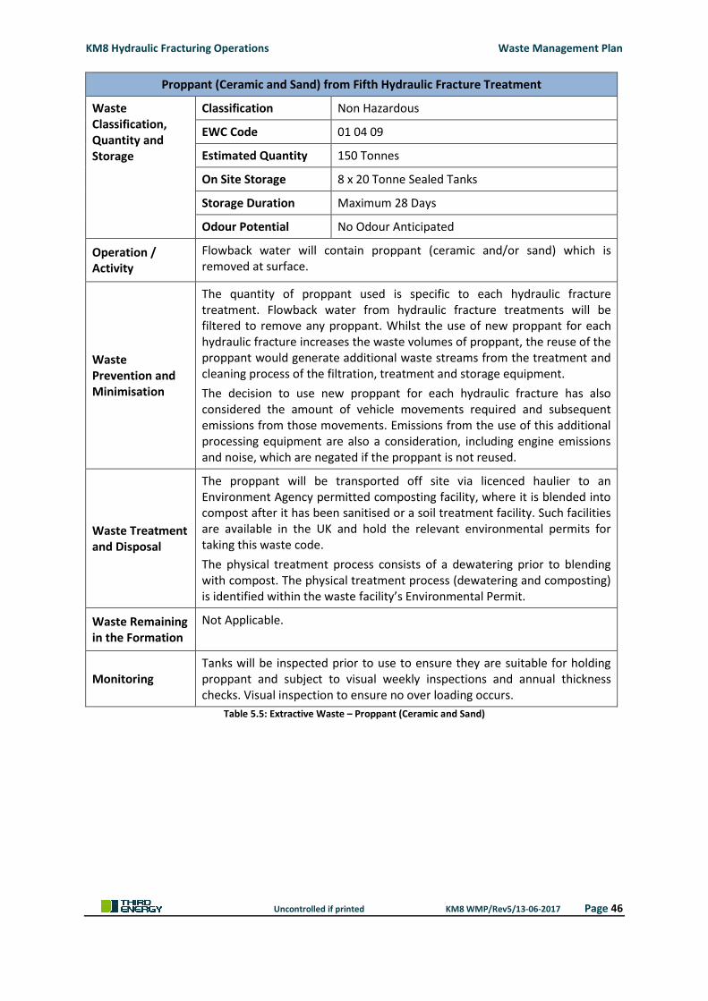
KM8 Hydraulic Fracturing Operations Waste Management Plan
Uncontrolled if printed KM8 WMP/Rev5/13-06-2017 Page 46
Proppant (Ceramic and Sand) from Fifth Hydraulic Fracture Treatment
Waste Classification, Quantity and Storage
Classification Non Hazardous
EWC Code 01 04 09
Estimated Quantity 150 Tonnes
On Site Storage 8 x 20 Tonne Sealed Tanks
Storage Duration Maximum 28 Days
Odour Potential No Odour Anticipated
Operation / Activity
Flowback water will contain proppant (ceramic and/or sand) which is removed at surface.
Waste Prevention and Minimisation
The quantity of proppant used is specific to each hydraulic fracture treatment. Flowback water from hydraulic fracture treatments will be filtered to remove any proppant. Whilst the use of new proppant for each hydraulic fracture increases the waste volumes of proppant, the reuse of the proppant would generate additional waste streams from the treatment and cleaning process of the filtration, treatment and storage equipment.
The decision to use new proppant for each hydraulic fracture has also considered the amount of vehicle movements required and subsequent emissions from those movements. Emissions from the use of this additional processing equipment are also a consideration, including engine emissions and noise, which are negated if the proppant is not reused.
Waste Treatment and Disposal
The proppant will be transported off site via licenced haulier to an Environment Agency permitted composting facility, where it is blended into compost after it has been sanitised or a soil treatment facility. Such facilities are available in the UK and hold the relevant environmental permits for taking this waste code.
The physical treatment process consists of a dewatering prior to blending with compost. The physical treatment process (dewatering and composting) is identified within the waste facility’s Environmental Permit.
Waste Remaining in the Formation
Not Applicable.
Monitoring Tanks will be inspected prior to use to ensure they are suitable for holding proppant and subject to visual weekly inspections and annual thickness checks. Visual inspection to ensure no over loading occurs.
Table 5.5: Extractive Waste – Proppant (Ceramic and Sand)
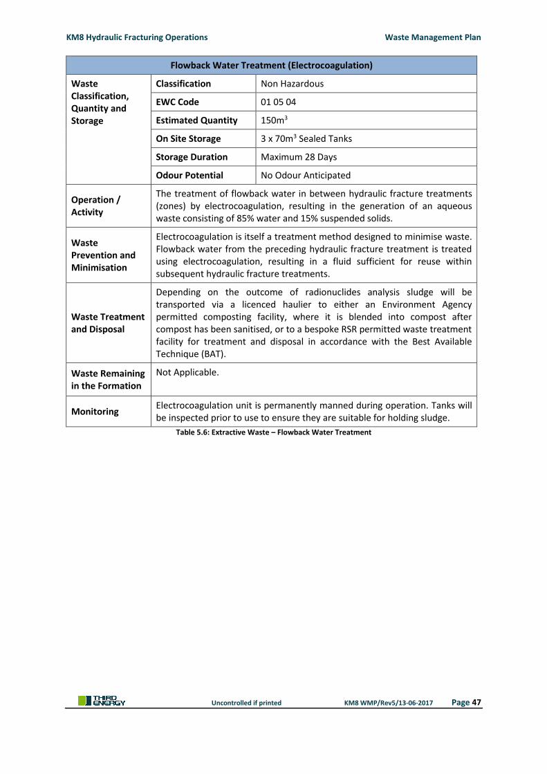
KM8 Hydraulic Fracturing Operations Waste Management Plan
Uncontrolled if printed KM8 WMP/Rev5/13-06-2017 Page 47
Flowback Water Treatment (Electrocoagulation)
Waste Classification, Quantity and Storage
Classification Non Hazardous
EWC Code 01 05 04
Estimated Quantity 150m3
On Site Storage 3 x 70m3 Sealed Tanks
Storage Duration Maximum 28 Days
Odour Potential No Odour Anticipated
Operation / Activity
The treatment of flowback water in between hydraulic fracture treatments (zones) by electrocoagulation, resulting in the generation of an aqueous waste consisting of 85% water and 15% suspended solids.
Waste Prevention and Minimisation
Electrocoagulation is itself a treatment method designed to minimise waste. Flowback water from the preceding hydraulic fracture treatment is treated using electrocoagulation, resulting in a fluid sufficient for reuse within subsequent hydraulic fracture treatments.
Waste Treatment and Disposal
Depending on the outcome of radionuclides analysis sludge will be transported via a licenced haulier to either an Environment Agency permitted composting facility, where it is blended into compost after compost has been sanitised, or to a bespoke RSR permitted waste treatment facility for treatment and disposal in accordance with the Best Available Technique (BAT).
Waste Remaining in the Formation
Not Applicable.
Monitoring Electrocoagulation unit is permanently manned during operation. Tanks will be inspected prior to use to ensure they are suitable for holding sludge.
Table 5.6: Extractive Waste – Flowback Water Treatment
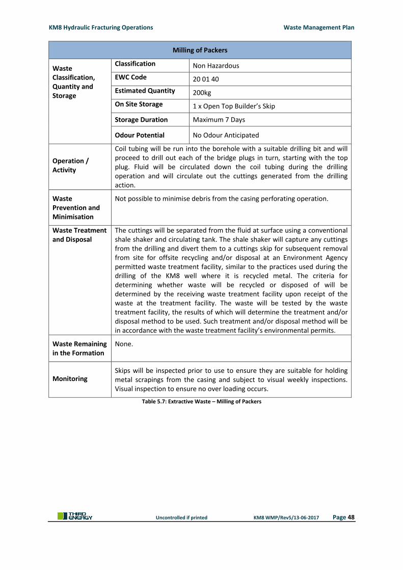
KM8 Hydraulic Fracturing Operations Waste Management Plan
Uncontrolled if printed KM8 WMP/Rev5/13-06-2017 Page 48
Milling of Packers
Waste Classification, Quantity and Storage
Classification Non Hazardous
EWC Code 20 01 40
Estimated Quantity 200kg
On Site Storage 1 x Open Top Builder’s Skip
Storage Duration Maximum 7 Days
Odour Potential No Odour Anticipated
Operation / Activity
Coil tubing will be run into the borehole with a suitable drilling bit and will proceed to drill out each of the bridge plugs in turn, starting with the top plug. Fluid will be circulated down the coil tubing during the drilling operation and will circulate out the cuttings generated from the drilling action.
Waste Prevention and Minimisation
Not possible to minimise debris from the casing perforating operation.
Waste Treatment and Disposal
The cuttings will be separated from the fluid at surface using a conventional shale shaker and circulating tank. The shale shaker will capture any cuttings from the drilling and divert them to a cuttings skip for subsequent removal from site for offsite recycling and/or disposal at an Environment Agency permitted waste treatment facility, similar to the practices used during the drilling of the KM8 well where it is recycled metal. The criteria for determining whether waste will be recycled or disposed of will be determined by the receiving waste treatment facility upon receipt of the waste at the treatment facility. The waste will be tested by the waste treatment facility, the results of which will determine the treatment and/or disposal method to be used. Such treatment and/or disposal method will be in accordance with the waste treatment facility’s environmental permits.
Waste Remaining in the Formation
None.
Monitoring Skips will be inspected prior to use to ensure they are suitable for holding metal scrapings from the casing and subject to visual weekly inspections. Visual inspection to ensure no over loading occurs.
Table 5.7: Extractive Waste – Milling of Packers
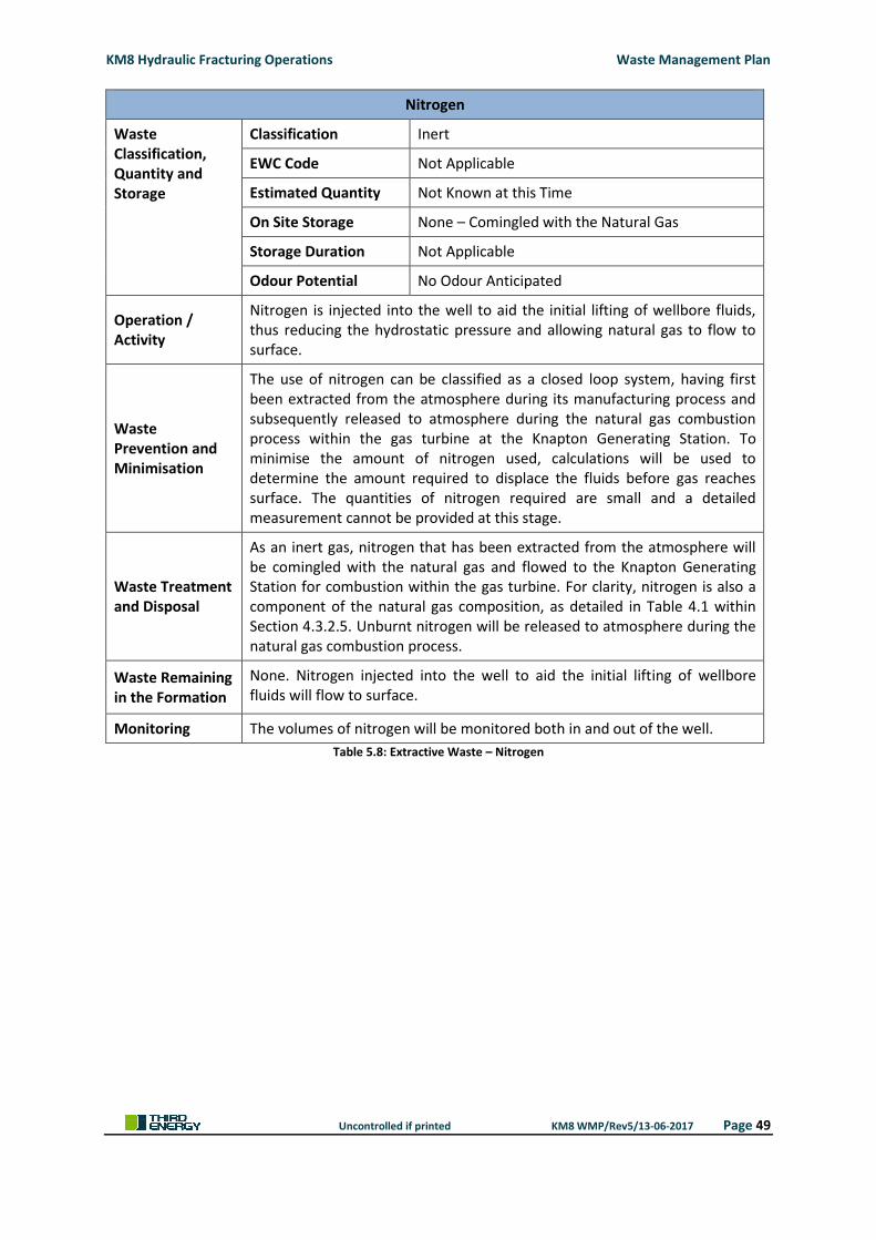
KM8 Hydraulic Fracturing Operations Waste Management Plan
Uncontrolled if printed KM8 WMP/Rev5/13-06-2017 Page 49
Nitrogen
Waste Classification, Quantity and Storage
Classification Inert
EWC Code Not Applicable
Estimated Quantity Not Known at this Time
On Site Storage None – Comingled with the Natural Gas
Storage Duration Not Applicable
Odour Potential No Odour Anticipated
Operation / Activity
Nitrogen is injected into the well to aid the initial lifting of wellbore fluids, thus reducing the hydrostatic pressure and allowing natural gas to flow to surface.
Waste Prevention and Minimisation
The use of nitrogen can be classified as a closed loop system, having first been extracted from the atmosphere during its manufacturing process and subsequently released to atmosphere during the natural gas combustion process within the gas turbine at the Knapton Generating Station. To minimise the amount of nitrogen used, calculations will be used to determine the amount required to displace the fluids before gas reaches surface. The quantities of nitrogen required are small and a detailed measurement cannot be provided at this stage.
Waste Treatment and Disposal
As an inert gas, nitrogen that has been extracted from the atmosphere will be comingled with the natural gas and flowed to the Knapton Generating Station for combustion within the gas turbine. For clarity, nitrogen is also a component of the natural gas composition, as detailed in Table 4.1 within Section 4.3.2.5. Unburnt nitrogen will be released to atmosphere during the natural gas combustion process.
Waste Remaining in the Formation
None. Nitrogen injected into the well to aid the initial lifting of wellbore fluids will flow to surface.
Monitoring The volumes of nitrogen will be monitored both in and out of the well.
Table 5.8: Extractive Waste – Nitrogen
KM8 Hydraulic Fracturing Operations Waste Management Plan
Uncontrolled if printed KM8 WMP/Rev5/13-06-2017 Page 50
5.3.2 Non-Extractive Waste
During the KM8 exploratory operations there may be non extractive wastes generated on site:
Surface run-off water;
Waste water and sewage;
Waste engine, gear and lubricating oils;
Waste hydraulic oils;
Oil rags and absorbents;
Waste oil filters;
Paper and cardboard;
Canteen waste;
Wood; and
Metal.
For clarity, the proposed development does not require nor does it propose the installation of a
permanent connection to the existing sewerage. During the short duration pre-stimulation workover
and hydraulic fracture stimulation/well test phases, when the number of personnel on site will be at
its greatest, temporary welfare facilities will be provided on site, each facility having an independent
under-unit sewage tank. During the production test phase and production phase, temporary welfare
facilities are provided within the security cabin. During the site restoration phase, temporary welfare
facilities are provided within the security cabin and/or ‘Portaloo’ type welfare facilities.
Sewage will be collected periodically throughout the short duration period when the wellsite is
manned and removed by licenced waste carrier to an Environment Agency permitted waste water
treatment works for subsequent treatment and/or disposal. The criteria for determining whether
waste will be recycled or disposed of will be determined by the receiving waste treatment facility
upon receipt of the waste at the treatment facility. The waste will be tested by the waste treatment
facility, the results of which will determine the treatment and/or disposal method to be used. Such
treatment and/or disposal method will be in accordance with the waste treatment facility’s
environmental permits.
There will be no treatment or disposal of non extractive waste onsite and any storage will be limited
to temporary storage, pending collection. No temporary storage of non extractive waste will exceed
12 months.
5.3.3 Waste Supervision and Carriers
A Site Supervisor will be appointed by Third Energy to oversee the KM8 hydraulic fracturing
operation, including the management of wastes onsite. The management of waste on site will
include:
Management of waste in accordance with the waste hierarchy, as set out in the Waste
(England and Wales) Regulations 2011 [Ref.19];
Monitor all waste storage units such as skips and storage tanks;
Liaise with third party waste advisors with respect to sampling and analysis of waste;
KM8 Hydraulic Fracturing Operations Waste Management Plan
Uncontrolled if printed KM8 WMP/Rev5/13-06-2017 Page 51
Compiling all waste transfer notes; and
Manage the collection and offsite disposal of all waste streams.
Third Energy will appoint competent waste dealers and carriers, responsible for the transportation
of all waste streams to the relevant Environment Agency permitted waste treatment facility. Waste
dealers and carriers will hold relevant certificates issued by the Environment Agency, which shall be
inspected prior to being appointed.
5.3.4 Wellsite Supervisor
Third Energy will appoint competent Wellsite Supervisor to oversee the KM8 hydraulic fracturing
operation. They will be responsible for the Health and Safety of personnel, contractors and public
and the implementation of any identified environmental requirements to ensure that operations do
not have an adverse impact on the environment during wellsite operations including waste
management. The onsite waste broker will report to the wellsite supervisor and provide advice
where necessary to ensure that the management of waste has been undertaken in compliance with
legislation and the waste hierarchy.
All Wellsite Supervisors will hold the relevant certificates and will be sufficiently experienced in
accordance with the Third Energy’s Business Management System, specifically the Contractor
Selection and Management Guidance Document. The appointed Wellsite Supervisor will have:
Minimum 5+ years’ experience in wellsite supervision and in oil and gas drilling and
production technologies;
Current IWCF certification;
Experience of well engineering, operation standards and applicable industry best practices;
Experience in emergency response procedures;
Understanding and application of applicable legislation, including but not limited to, the
Offshore Installation and Wells (Design and Construction Etc.) Regulations 1996 [Ref.20],
Borehole Sites and Operations Regulation 1995 [Ref.21] and be aligned with any revisions
therewith.
KM8 Hydraulic Fracturing Operations Waste Management Plan
Uncontrolled if printed KM8 WMP/Rev5/13-06-2017 Page 52
6. ENVIRONMENTAL RISK ASSESSMENT
An Environmental Risk Assessment has been carried out in support of the permit application and is
based upon the Horizontal Guidance Note H1 Environmental Risk Assessment for permits. (Version
2.1, December 2011) [Ref.22] and the EPR6 14: How to comply with your environmental permit:
Additional guidance for: mining waste operations, Version 2, February 2011 [Ref.23].
The environmental risk assessment follows the following H1 structure:
Identify the risk from the activity
Assess risks and check they are acceptable
Justify appropriate measures to control the risk (if needed)
Present the risk assessment
Of the 10 (10) annexes that together form the Horizontal Guidance for the environmental risk
assessment, the following annexes have been included. Annexes not referenced below are not
relevant to the proposed KM8 hydraulic fracturing operation:
Annex (a) Amenity and accident risks from installations and waste operations
Annex (d) Discharges to Surface Water
Annex (f) Air emissions
Annex (g) Disposal and recovery of waste produced on site
Annex (h) Global warming potential
Annex (j) Groundwater
A copy of the environmental risk assessment, together with a supporting statement and
conventional model is included within ‘KM8 Environmental Risk Assessment’ (TE-EPRA-KM8-HFS-
ERA-07) provided in support of the environmental permit application.
KM8 Hydraulic Fracturing Operations Waste Management Plan
Uncontrolled if printed KM8 WMP/Rev5/13-06-2017 Page 53
7. MEASURES TO MINIMISE ENVIRONMENTAL IMPACT
Measures to minimise the environmental impact of the operation have been incorporated as part of
the initial site selection process, site design and construction through to subsequent exploration
operations. The measures to mitigate long term environmental impact are:
Site located suitable distance from residential properties
Site located away from any statutory designated areas
Baseline monitoring of ecology, noise, water
Hydrogeological risk assessment
Site design to include impermeable membrane and containment ditches
Wellbore lifecycle design to protect groundwater
Hierarchy of waste management
Operating procedures and inductions
Waste handling, storage and disposal regime
Continuous Training and development
Environmental monitoring
Restoration and aftercare
KM8 Hydraulic Fracturing Operations Waste Management Plan
Uncontrolled if printed KM8 WMP/Rev5/13-06-2017 Page 54
8. CONTROL AND MONITORING OF WASTE
The environmental risk assessment has identified the requirement to control and monitor waste
generated from the KM8 hydraulic fracturing operation. A brief description of the control and
monitoring of waste is provided below, with a separate Emission Monitoring Plan (TE-EPRA-KM8-
HFS-9) provided in support of the environmental permit application.
8.1 RELEASES TO GROUNDWATER
The potential for a release to groundwater exists both at surface and within subsurface and has been
assessed by way of a Hydrogeological Impact Assessment, which is included with the KMA Site
Condition Report (TE-EPRA-KM8-HFS-SCR-06), submitted together with this Waste Management Plan
in support of the KM8 hydraulic fracturing environmental permit application.
A baseline groundwater quality for the KMA wellsite has been established, which is described in
detail within the KMA Site Condition Report (TE-EPRA-KM8-HFS-SCR-06).
8.1.1 Surface Release
Incorporated into the design of the Kirby Misperton 1 extension is an impermeable membrane
constructed using fully welded 1mm HDPE, protected above and below by non-needle punch
geotextile. The impermeable membrane prevents surface fluids (mainly rainwater) penetrating the
underlying subsoils. Surface fluids migrate along the surface of the impermeable membrane to a
perimeter ditch, where it is contained for subsequent reuse in the operation or removed via road
tanker to an Environment Agency approved waste water treatment works for subsequent treatment
and disposal.
The original wellsite is clay lined and the existing production equipment bunded. All equipment
associated with the KM8 hydraulic fracturing, which is to be located within the Kirby Misperton 1
wellsite will be sited upon an impermeable membrane with bunded walls.
Daily inspections of the drainage ditch and bunds are undertaken to ensure the level does not
exceed the maximum containment. If the level is close to reaching the maximum containment, the
surface fluids are removed by road tanker for subsequent disposal at an approved waste facility.
A daily inspection of all tanks and other waste storage containers shall be undertaken to ensure they
remain fit for purpose. The inspections will aid early identification of any potential release to site
from equipment which deteriorates over time.
8.1.2 Subsurface Release
Risks are mitigated by adopting the best practice approach to wellsite construction, well
construction and management of the hydraulic fracturing operation described in this planning
application, Environmental Statement and Environmental Permit Application.
KM8 Hydraulic Fracturing Operations Waste Management Plan
Uncontrolled if printed KM8 WMP/Rev5/13-06-2017 Page 55
8.1.3 Groundwater Quality Monitoring
A scheme of groundwater quality monitoring, which has been discussed with the Environment
Agency and their comments taken on board, provides for the monitoring of groundwater quality
prior to, during and after the KM8 hydraulic fracturing operation. Results of the groundwater quality
monitoring scheme will be made available for inspection by the Environment Agency and will form
part of the monthly emissions submission as part of the environmental permit.
8.2 RELEASES TO AIR
Baseline air quality has been established for the KMA wellsite, which is described in detail within the
KMA Site Condition Report (TE-EPRA-KM8-HFS-SCR-06).
The potential for a release to air has been assessed by way of a Air Quality Impact Assessment,
which is included as Appendix 8 and submitted in support of the KM8 hydraulic fracturing
environmental permit application. The Air Quality Impact Assessment considers all phases of the
proposed development and assesses their impacts against Air UK Air Quality Standards (AQS)
[Ref.24]. The proposed development does not contemplate flaring of natural gas and therefore the
Air Quality Impact Assessment assesses the impacts from vehicle and equipment emissions and
fugitive emissions. For clarity, whilst the Air Quality Impact Assessment takes into consideration all
equipment and vehicles associated with the KM8 hydraulic fracturing, for the purpose of this Waste
Management Plan, only emissions to air resulting from the management of extraction waste will be
regulated by the Environment Agency.
The Air Quality Impact Assessment concludes that the well operations will not affect the attainment
of air quality standards around the areas of permanent human habitation closest to the wellsite and
will have negligible impact at local statutory designated conservation sites. Exceedances in short
term air quality standards for some pollutants are likely on occasions around the site boundary
during the hydraulic fracturing operation due to the equipment being operated on site.
A scheme of air quality monitoring will be undertaken during the KM8 hydraulic fracturing operation
to monitor compliance with AQOs or relevant Limit Value. Results of the air quality monitoring
scheme will be made available for inspection by the Environment Agency and will form part of the
monthly emissions submission as part of the environmental permit.
8.3 NOISE
Baseline noise monitoring was undertaken over a two week period in February/ March 2015 to
determine the background noise levels at the nearest sensitive receptors.
The potential for noise to be generated has been assessed by way of a Noise Impact Assessment,
which has been submitted in support of the KM8 hydraulic fracturing planning application. The
average sound power level of a typical workover rig, the highest noise generating hydraulic fracture
equipment, pumps and blenders and production equipment was then modelled to give a predication
of the noise levels to be anticipated during these operational phases at the nearest sensitive
receptors.
KM8 Hydraulic Fracturing Operations Waste Management Plan
Uncontrolled if printed KM8 WMP/Rev5/13-06-2017 Page 56
For clarity, whilst the Noise Impact Assessment takes into consideration all equipment and vehicles
associated with the KM8 hydraulic fracturing, for the purpose of this Waste Management Plan, only
noise emissions resulting from the management of extraction waste will be regulated by the
Environment Agency.
Nosie modelling indicates that the pre-stimulation workover and hydraulic fracture stimulation
phases will be likely to generate the highest noise levels, however, these two operational phases
have a short combined duration of eight (8) weeks. Additional mitigation during the pre-stimulation
workover and hydraulic fracture stimulation phases will be provided. Noise modelling of the
production test and subsequent production indicates noise levels will be extremely low and below
the background noise levels at the nearest sensitive receptors.
The Noise Impact Assessment concludes that noise generated during the five (5) operational phases
will fall within noise levels set within applicable planning practice guidance.
A scheme of noise monitoring will be undertaken during the KM8 hydraulic fracturing operation to
monitor compliance with noise limit values. Results of the noise monitoring scheme will be made
available for inspection by the Environment Agency.
The methodology covering noise monitoring is provided within the KM8 Emissions Monitoring Plan
(TE-EPRA-KM8-HFS-EMP-09).
8.4 WELLSITE MONITORING
Throughout the KM8 hydraulic fracturing operation and subsequent production of natural gas,
environmental monitoring will be undertaken at the KMA wellsite.
Environmental monitoring is undertaken by the Wellsite Supervisor and service personnel during
operations to identify potential leaks and emissions from site equipment and materials stored within
the site. This ensures that any action required to remediate leaks or emissions can be undertaken as
soon as they are identified and prevent potential impact on the environment. Environmental
monitoring includes inspection of site perimeter ditches, site surface, bunds, storage tanks, sewage
facilities, site equipment and any materials stored within the wellsite.
A written record of monitoring (Environmental Checklist) is completed once per 12 hour shift by the
Wellsite Supervisor and submitted at the end of shift. Copies of the Environmental Checklist are held
on site and are made available for review by the Environment Agency.
On completion of the KM8 hydraulic fracturing operation, environmental monitoring will be
undertaken by the production operators who visit the wellsites on a daily basis.
8.5 CONTRACTOR PERFORMANCE
Third Energy is ultimately responsible for any waste generated on site during the KM8 hydraulic
fracturing operations. Third Energy will not delegate its responsibilities or accountabilities as
Operator to a contractor.
KM8 Hydraulic Fracturing Operations Waste Management Plan
Uncontrolled if printed KM8 WMP/Rev5/13-06-2017 Page 57
Contractors, who are involved in the generating of waste and subsequent reuse, recycle or disposal
will first have been selected in accordance with Third Energy’s Contractor Selection and
Management Guidance Document (TE_HSEMS_GD02) and, under that standard, are then subject to
periodic monitoring of their performance.
8.6 SECURITY
Security of the wellsite is provided in the form of fencing and lockable gates. Additional fencing is
provided around the wellhead when the site is unmanned. A CCTV camera is also active when the
site is unmanned and a roaming security detail is provided, carrying out routine visits to the wellsite.
During well operations, 24 hours onsite security is provided. Security control access and egress to
the wellsite and will play a key role in the control of personnel in the event of an emergency
situation, in accordance with the Site Safety Document, a requirement of the Borehole Sites and
Operations Regulations 1995.
8.7 COMPLAINTS
In the event that a complaint is received from stakeholders, including neighbours, the complaint
shall be recorded and investigated in accordance with Third Energy’s health, safety and
environmental management system.
Complaints relating to the environment will be reported to the Environment Agency within the
required timescales, as determined by the severity and environmental impact of the incident
initiating the complaint and/or permit conditions. In some cases, permit conditions may require
notification the Environment Agency within 24 hours or without delay for a potentially polluting
incident.
Following notification, measures to prevent reoccurrence will be agreed with the Environment
Agency, together with a programme for implementation. Implementation of the actions will be
monitored and the Environment Agency informed.
KM8 Hydraulic Fracturing Operations Waste Management Plan
Uncontrolled if printed KM8 WMP/Rev5/13-06-2017 Page 58
9. ENVIRONMENTAL INCIDENT MANAGEMENT
The potential for an environmental incident to occur during the operation is minimal. The source of
such incident is contained within the wellbore and contained within the wellsite.
9.1 CONTAMINATION WITHIN THE WELLBORE
Well control equipment is deployed on the well in accordance with API RP53 ‘Recommended
Practice for Blowout Prevention Equipment Systems for Drilling Wells’ [Ref.26]. Well control
equipment is considered secondary well control in the event that the primary well control,
hydrostatic fluid weight, is compromised. Well control equipment is subject to a schedule of
certification and testing, together with a requirement for those operating well control equipment to
be certified competent.
9.2 WELLSITE CONTAINMENT
The proposed development is being undertaken within an existing wellsite. Incorporated into the
design of the Kirby Misperton 1 extension is an impermeable membrane constructed using fully
welded 1mm HDPE, protected above and below by non-needle punch geotextile. The impermeable
membrane prevents surface fluids (mainly rainwater) penetrating the underlying subsoils. Surface
fluids migrate along the surface of the impermeable membrane to a perimeter ditch, where it is
contained for subsequent reuse in the operation or removed via road tanker to an Environment
Agency approved waste water treatment works for subsequent treatment and disposal.
The original wellsite is clay lined and the existing production equipment bunded. All equipment
associated with the KM8 hydraulic fracturing, which is to be located within the Kirby Misperton 1
wellsite will be sited upon an impermeable membrane with bunded walls.
In addition to general spill containment and clean up equipment provided on site, a substantial
environmental incident response trailer is provided. The trailer contains equipment necessary to
minimise and if possible contain an environmental incident in the unlikely event that the
impermeable membrane or containment ditch is compromised. The equipment provides for
damming of any nearby water course and subsequent clean up, including temporary bunding of
spent clean-up equipment.
In the very unlikely event of an environmental incident occurring beyond the capabilities of the
equipment or personnel on site then a specialist contractor, for example Veolia Environmental
Services, will be called to assist Third Energy in dealing with the incident.
9.3 FIRE RESPONSE
Whilst a fire is associated more so with the health and safety of the personnel on site, a fire does
have the potential to lead to an environmental incident. It is imperative, therefore, that any
potential for a fire and subsequent emergency response is identified and included in the operational
planning. The Site Safety Document, which is a requirement under Regulation 7 of the Boreholes
KM8 Hydraulic Fracturing Operations Waste Management Plan
Uncontrolled if printed KM8 WMP/Rev5/13-06-2017 Page 59
Sites and Operations Regulations 1995, specifies the arrangements for identification and mitigation
in the event of a fire, including consultation with the local Fire & Rescue Service.
Containment of any firefighting fluid is provided by the impermeable membrane incorporated in to
the design of the wellsite. In the event that such requirements were to be necessary, continued
monitoring of the containment ditch shall be implemented to ensure it does not exceed its
containment capacity.
Additional water is available on site and should be used to keep the areas adjacent to the fire cool to
avoid any damage being sustained to the impermeable membrane.
9.4 INCIDENT REPORTING AND INVESTIGATION
All incidents, no matter how minor, are reported in accordance with Third Energy’s Reporting of
Accidents, Environmental Incidents and Near Misses Standing Instruction (SI-08). The procedure
provides for the investigation of all incidents to ensure lessons are captured and actions
implemented to avoid reoccurrence.
In addition, the standard provides for the notification to the relevant Regulatory Authority in the
event of an incident which extends beyond the containment of the wellsite.
Environmental incidents will be reported to the Environment Agency within the required timescales,
as determined by the severity and environmental impact of the incident and/or permit conditions. In
some cases, permit conditions may require notification the Environment Agency within 24 hours or
without delay for a potentially polluting incident.
Following notification, measures to prevent reoccurrence will be agreed with the Environment
Agency, together with a programme for implementation. Implementation of the actions will be
monitored and the Environment Agency informed.
KM8 Hydraulic Fracturing Operations Waste Management Plan
Uncontrolled if printed KM8 WMP/Rev5/13-06-2017 Page 60
10. ALTERATIONS TO THE PLAN
Any required changes or deviations from this plan are to be referred to the Third Energy HSE
Manager or to the site HSE Adviser in the first instance. No changes to or deviations from this plan
are to be implemented until the required changes or deviations have been reviewed and approved
by Third Energy and the relevant approvals obtained in writing from the Environment Agency for any
changes to the plans and operating techniques approved under the environmental permit to be
issued.
Within the environmental permit there will be a requirement for the operator, Third Energy, to
review the waste management plan every five (5) years and amend where necessary. The review
date shall take place five (5) years from the date of permit issue. Reviews and amendments will also
be required in the event of a substantial change(s) to the operations taking place onsite.
In some cases, changes to operations may require the environmental permit to be varied in order to
accommodate such changes. In this instance an application will be made to the Environment Agency
to vary the existing permit or apply for a new permit.
KM8 Hydraulic Fracturing Operations Waste Management Plan
Uncontrolled if printed KM8 WMP/Rev5/13-06-2017 Page 61
11. PLAN FOR CLOSURE
The wellsite is currently being used for petroleum exploration and production activities.
In the event that the well(s) is deemed not capable of producing commercial quantities of petroleum
a decision will be made to abandon the well in accordance with Oil & Gas UK Guidelines for the
suspension and abandonment of wells [Ref.27] and restore the site. In such an event, a closure plan
will be created in accordance with section 3.4 of the Environment Agency’s guidance “How to
comply with your environmental permit, additional guidance for: mining waste operations” as part
of any application to surrender the environmental permit. Wellsite restoration will be the subject of
a separate waste management plan.
Other regulations relevant to the closure plan include:
The Borehole Sites and Operations Regulations 1995 [Ref.21],
Offshore Installations and Wells (Design & Construction Regulations 1996 [Ref.20], and
Petroleum Act 1998 (Petroleum Exploration and Development Licence) [Ref.28].
KM8 Hydraulic Fracturing Operations Waste Management Plan
Uncontrolled if printed KM8 WMP/Rev5/13-06-2017 Page 62
12. REFERENCES
Ref.1: Secretary of State
Ref.2: Department for Energy and Climate Change
Ref.3: Department of Energy and Climate Change Petroleum Licensing system
Ref.4: Town and Country Planning Act, 1990
Ref.5: Natural England Agricultural Land Classification Maps, 2011
Ref.6: Environment Agency What’s in your Backyard
Ref.7: North Yorkshire County Council Planning Application Decision Notice: C3/12/00989/CPO
Ref.8: Environmental Permitting (England & Wales) Regulations 2016
Ref.9: Water Resources Act, 1991
Ref.10 Water Act, 2003
Ref.11: Directive 2006/21/EC of the European Parliament and of the Council, 15 March 2006: on the
management of waste from extractive industries and amending Directive 2004/35/EC
Ref.12: Environment Agency Guidance notes on part B5 – New bespoke mining waste operation
permit, 2013
Ref.13: European Commission Council Directive 91/689/EEC on hazardous waste
Ref.14: European Commission Council Directive 67/548/EEC on the approximation of laws,
regulations and administrative provisions relating to the classification, packaging and
labelling of dangerous substances (Dangerous Substances Directive)
Ref.15: European Commission Council Directive 1999/45/EC concerning the approximation of the
laws, regulations and administrative provisions of the Member States relating to the
classification, packaging and labelling of dangerous preparations (Dangerous Preparations
Directive)
Ref.16: European Commission Council Directive 2010/75/EU on industrial emissions (integrated
pollution prevention and control) (Industrial Emissions Directive)
Ref.17: Consent to Discharge (NPSWQD001330), February 2010: Discharge Trade Effluent
comprising formation water and gas condensate from the gas extraction wells and Knapton
Generating Station
Ref.18: European Commission Council Directive 2000/60/EC establishing a framework for
Community action in the field of water policy (The EU Water Framework Directive -
integrated river basin management for Europe)
KM8 Hydraulic Fracturing Operations Waste Management Plan
Uncontrolled if printed KM8 WMP/Rev5/13-06-2017 Page 63
Ref.19: Waste (England and Wales) Regulations, 2011
Ref.20: Health and Safety Commission Offshore Installation and Wells (Design and Construction etc.)
Regulations, 1996
Ref.21: Health and Safety Commission Borehole Sites and Operation Regulations, 1995
Ref.22: Environment Agency, Horizontal guidance note H1, 2011
Ref.23: Environment Agency EPR 6.14 How to comply with your environmental permit. Additional
guidance for: mining waste operations, 2011
Ref.24: Department for Environment Food and Rural Affairs Air UK Air Quality Standards
Ref.25: Department of Communities and Local Government Planning Practice Guidance, 2014
Ref.26: American Petroleum Institute Recommended Practices for Blowout Prevention Equipment
Systems for Drilling Wells Standard
Ref.27: Oil and Gas UK Guidelines for the Suspension and Abandonment of Wells, 2012
Ref.28: Petroleum Act, 1998 (Petroleum Exploration and Development Licence)

KM8 Hydraulic Fracturing Operations Waste Management Plan
Uncontrolled if printed KM8 WMP/Rev5/13-06-2017 Page 64
APPENDIX 1 – THIRD ENERGY CORPORATE INFORMATION

KM8 Hydraulic Fracturing Operations Waste Management Plan
Uncontrolled if printed KM8 WMP/Rev5/13-06-2017 Page 65
**This page has been intentionally left blank**
KM8 Hydraulic Fracturing Operations Waste Management Plan
Uncontrolled if printed KM8 WMP/Rev5/13-06-2017 Page 66
THIRD ENERGY CORPORATE INFORMATION
Registered Office
Third Energy UK Gas Limited
Knapton Generating Station
East Knapton
Malton
North Yorkshire
YO17 8JF
Company Registration No: 01421481
Principal Office
Third Energy UK Gas Limited
Portland House
Bressenden Place
Westminster
London
SW1E 5BH
Tel: 0207 042 0800
Web: www.third-energy.com
Operational Office
Third Energy UK Gas Limited
Knapton Generating Station
East Knapton
Malton
North Yorkshire
YO17 8JF
Tel: 01944 758 746

KM8 Hydraulic Fracturing Operations Waste Management Plan
Uncontrolled if printed KM8 WMP/Rev5/13-06-2017 Page 67
**This page has been intentionally left blank**

KM8 Hydraulic Fracturing Operations Waste Management Plan
Uncontrolled if printed KM8 WMP/Rev5/13-06-2017 Page 68
APPENDIX 2 – THIRD ENERGY ENVIRONMENTAL RISK MANAGEMENT SYSTEM

KM8 Hydraulic Fracturing Operations Waste Management Plan
Uncontrolled if printed KM8 WMP/Rev5/13-06-2017 Page 69
**This page has been intentionally left blank**
Page 1 of 13 Issue 05
THIRD ENERGY UK GAS LIMITED
KNAPTON GENERATING STATION
ENVIRONMENTAL MANAGEMENT SYSTEM
ENVIRONMENTAL MANAGEMENT SYSTEM MANUAL
REVIEWED BY ISSUE No DATE
S.Zablocki
OSM
06 11th September 2015
AUTHORISED BY ISSUE No DATE
M.Lea
Station Manager
06 11th September 2015
ENVIRONMENTAL MANAGEMENT SYSTEM MANUAL
Page 2 of 13 Issue 05
1. INTRODUCTION
The purpose of this document is to provide guidance on the EnvironmentalManagement System (EMS) that is in operation in Knapton Generating Stationand related well sites.
The scope of the Environmental Management System is all operations andactivities related to Knapton Generating Station and related well sites.
It seeks to demonstrate the manner in which compliance with current legislationand regulations, as well as Company, Business and Station objectives andtargets are achieved.
It identifies those persons with environmental responsibilities and signpostsother station documentation where further information is available.
An Environmental Policy Statement, regular audits and reviews and the settingof an Annual Environmental Plan all contribute to the goal of continualimprovement in environmental performance.
The Environmental Management System is based on the International Standardfor Environmental Management Systems ISO 14001.
2. ENVIRONMENTAL POLICY STATEMENT
Knapton Generating Station has an environmental policy statement(incorporated into a combined Health, Safety and Environment Policy), a signedcopy of which is always posted on the notice board.
Copies of this policy can be made available on request from the public, and iscommunicated internally to all staff and contractors working at KnaptonGenerating Station and related well sites.
The policy statement will be reviewed and if necessary updated annually.
3. ENVIRONMENTAL ASPECTS
The environmental aspects of operations, activities, products and services withinKnapton Generating Station and related well sites are identified and theirsignificance assessed.
Aspects that have a significant environmental impact are taken into account inestablishing, implementing and maintaining the Environmental ManagementSystem.
The procedure for the assessment of environmental aspects and all assessedenvironmental aspects are kept on file.
ENVIRONMENTAL MANAGEMENT SYSTEM MANUAL
Page 3 of 13 Issue 05
4. LEGAL AND OTHER REQUIREMENTS
The procedure that will establish, implement and maintain the legal and otherrequirements related to the environmental aspects of Knapton GeneratingStation is Legal and Other Requirements.
5. ENVIRONMENTAL PLAN
Environmental targets and objectives are set annually to minimise the risk ofsignificant environmental impacts of various activities as they are identified inthe Register of Environmental Impacts.
The plan is developed by the Station Manager in consistency with theEnvironmental Policy to reflect improvements that can be made to reduce theseimpacts. Management objectives and planned improvements that relate toenvironmental issues and views of relevant interested parties are also consideredand fed into the plan.
The Environmental Plan is endorsed at the Health, Safety & EnvironmentCommittee meeting and signed by the Station Manager. The contents of thePlan are communicated to those persons with responsibilities therein.
The Environmental Plan is audited monthly at the Committee meeting andprogress assessed. Targets and dates are revised if necessary with reasons forchanges documented in the relevant audit report.
A copy of the plan is in the control room and it can be available to staff andcontractors.
6. STRUCTURE AND RESPONSIBILITIES
Specific responsibilities for the implementation of the EnvironmentalManagement System are as follows:
Station Manager
The Station Manager is responsible for the authorisation and implementation ofthe Environmental Policy at Knapton Generating Station. He will:
1. Prepare and maintain details for the organisation and arrangements forimplementing the policy.
2. Set Environmental Objectives and Targets to ensure a continuousimprovement in environmental performance.
3. Carry out an annual review of the Environmental Performance andimplementation of Environmental Objectives and Targets.
ENVIRONMENTAL MANAGEMENT SYSTEM MANUAL
Page 4 of 13 Issue 05
4. Allocate responsibilities to the managers to establish, update and review,Operating Procedures, Standing Instructions and EnvironmentalManagement Procedures to ensure the implementation of theEnvironmental Policy and of Legal and Other Requirements.
5. Allocate resources under his control as necessary to provide andmaintain conditions and places of work that are, so far as is reasonablypracticable, safe and without risks to the environment.
6. Ensure that the plant is operated in order to minimise its impact on theenvironment.
7. Ensure that environmental arrangements are monitored on an activebasis including Audits, Tours and workplace inspections are carried outand appropriate action initiated to secure continuing compliance inaccordance with the policy.
8. Act as the Chairman of the Health, Safety and Environment Committee,ensure that the Environmental Management System is implemented, andencourage a proactive culture.
9. Ensure that all aspects of the plant PPC authorizations for KnaptonGenerating Station are fully complied with and all staff are familiar withthe limits imposed by them.
10. The Station Manager will carry out the function of Waste ControlEngineer.
O&M Supervisor
The O&M Supervisor is responsible for the implementation of the Company'sEnvironmental Policy at Knapton Generating Station as it affects employeesunder his control. In particular, he will:
1. Ensure that all staff under his control are familiar with the policy and itsimplementation.
2. Overview the implementation of the annual Environmental Objectivesand Targets for all employees under his control and carry out regularreviews to ensure a continuous improvement in environmentalperformance.
3. Implement and maintain a register of relevant Environmental Legislationin consultation with all information providers in accordance with therequirements of the Environmental Management System.
4. Ensure staff under his control are provided with training and refreshertraining where appropriate. The Administrator shall keep all records oftraining.
ENVIRONMENTAL MANAGEMENT SYSTEM MANUAL
Page 5 of 13 Issue 05
5. Ensure that all accidents, near misses and incidents are reported andinvestigated as per the Station Procedure and that remedial action isinitiated to prevent a re-occurrence.
6. Monitor environmental arrangements on an active basis by carrying outregular audits, tours and inspections involving staff and employees toensure continuing compliance in accordance with the policy andstatutory requirements.
7. Monitor Emissions from the plant, which are to be reported under therequirements of the site PPC Permit, and prepare reports to satisfy thoserequirements as described in the Emissions Monitoring Procedure.
8. Participate in establishing, updating and reviewing, OperationalProcedures, Standing Instructions and Environmental ManagementProcedures employed at Knapton Generating Station.
9. Ensure that environmental management system requirements areestablished, implemented, and maintained in accordance with ISO14001.
10. Review of other plant documentation as required taking account ofenvironmental issues.
11. Reporting on the performance of the environmental management systemto management for review and as a basis for its improvement.
12. Ensure that the plant is operated to minimise its impact on theenvironment.
13. The O&M Supervisor will also carry out the functions of EnvironmentalCo-ordinator and Waste Control Co-ordinator.
Lead Operators, Operators and Maintenance Staff
The Lead Operators, Operators and Maintenance Staff are responsible for theimplementation of the Company's Environmental Policy at Knapton GeneratingStation. In particular, they will:
1. Ensure they are familiar with the policy and its implementation.
2. Implement environmental arrangements to ensure continuing compliancein accordance with the policy and statutory requirements.
3. Ensure that the plant is operated to minimise its impact on theenvironment. Monitor effluent discharge, plant chemistry, and ensureplant is operated within specified limits.
ENVIRONMENTAL MANAGEMENT SYSTEM MANUAL
Page 6 of 13 Issue 05
To help further in attaining high environmental standards employees can, forexample:
Ensure that any potential hazards are reported promptly to theappropriate supervisor.
Report shortcomings in the Station's environmental arrangements.
Assist where necessary in carrying out Environmental RiskAssessments.
Administration
The Administrator will:
Manage all Monitoring and Training Records and ensure adequate noticeis given to arrange all required refresher and statutory training.
7. TRAINING, AWARENESS AND COMPETENCE
All staff are trained in the specific environmental aspects and responsibilities oftheir jobs, in emergency procedures and the potential consequences of departingfrom the specific procedures. This also includes the Environmental Policy, themajor impacts of the organisation’s activities and an introduction to the EMS.Where an activity has the potential to cause significant environmental impacts,care is taken that it is assigned to competent staff.
Training needs are identified, the training is provided and training records areheld centrally at Administration. This is done with the help of theEnvironmental Training Matrix.
The Station Manager, in conjunction with station staff, will complete the TrainingMatrix by identifying those persons with environmental duties and identifyingappropriate training that is required fulfilling those duties.
The Training Matrix will be reviewed at the HS&E committee.
Environmental training shall ensure that all employees are aware of:
The importance of conformance with the Environmental Policy,procedures and the requirements of the Environmental ManagementSystem.
The significant environmental impacts, actual or potential, of their workactivities and the environmental benefits of improved personalperformance.
Their roles and responsibilities in achieving conformance with theenvironmental policy and procedures and with the requirements of the
ENVIRONMENTAL MANAGEMENT SYSTEM MANUAL
Page 7 of 13 Issue 05
environmental management system, including emergency preparednessand response requirements.
The potential consequences of departure from specified operatingprocedures.
Employees whose responsibilities include areas covered by environmentalprocedures shall be trained in those procedures. Further training in therequirements of environmental procedures shall be performed when there is eithera change in staff or a significant revision to the procedure.
Environmental awareness shall remain ongoing via a variety of initiatives,including toolbox talks and information on the Environmental Notice Board, co-ordinated by the Station Manager.
Care will be taken that contractors are made aware on site induction of theEnvironmental Policy and Plan, procedures and the environmental significance oftheir actions.
8. COMMUNICATION
Communication of Environmental Information either internally or externallywill be done according to the procedures identified in the document:Communication of Environmental Information
9. DOCUMENTATION AND DOCUMENT CONTROL
All documents in Knapton Generating Station will be created, amended andwithdrawn according to the procedure SI – 11: Document control.
10. OPERATIONAL CONTROL
Operations and activities in Knapton Generating Station and related well sitesthat are associated with the identified significant environmental aspects areidentified and procedures are in place to control them.
These can be Standing Instructions, Operating Procedures or EnvironmentalManagement procedures. They will ensure compliance with the EnvironmentalPolicy, with Legal and other Requirements and the progress of theEnvironmental Plan.
11. EMERGENCY PREPAREDNESS AND RESPONSE
Emergency procedures are established in the event of a fault or malfunction innormal operating equipment, procedure or a situation that could result in:
A threat to the health and safety of personnel either on or off site, Damage to plant or buildings either on or off site or,
ENVIRONMENTAL MANAGEMENT SYSTEM MANUAL
Page 8 of 13 Issue 05
Polluting the environment.
A copy of the Emergency Procedures is always kept in the Control Room.
12. ENVIRONMENTAL SITE PLANS
Environmental site layout plans will be prepared for the Knapton GeneratingStation and related well sites. Environmental site layout plans shall be to scaleand include the following environmental information:
An accurate representation of the main features of the site; The activities carried out and any discharge points; Drainage plans, which identify both surface and foul drains (if applicable)
and the final destination of any drain; The location of any waste activities, such as waste storage areas, whether
full or empty; The location of any oil and chemical storage areas and/or facilities; The location of any important or sensitive receptors, including nearby
surface water features, groundwaters or sensitive wildlife areas; and The location of any known or potentially contaminated land within the site.
In order to capture all the environmental information associated with theKnapton Generation Station or related well sites within accurate and scaledplans, it may be necessary to have more than one plan per site.
Environmental site layout plans shall be created, amended and withdrawnaccording to the procedure SI – 11: Document control. They shall be reviewedannually or in advance of process changes or non-routine works beingundertaken at the site.
13. MONITORING AND MEASUREMENT
NOx and SOx emissions are measured continuously by the Control RoomDistributed Control System (DCS) and the cumulative amount emitted is storedon file. The maximum concentration is set by the PPC Authorisation andcompliance with the limit is demonstrated if 95% of the half hourly averagereadings for each rolling 24-hour period do not exceed the limit values, and thepeak value does not exceed three times the limit value.
The calibration of the panel is done automatically each 24 hours and specialistswill perform regular maintenance checks on the panel.
A limit of 50 mg/m3 (30.7 ppm Vol. 1) of HCl emissions is set Third Energy anddelivery is to cease and work order raised for scrubber repair. A measurement istaken by the Operator during the first acid delivery of the month and the result isrecorded in the Environmental log book.
The Operator will also perform a pH analysis of the filtering water after the firstdelivery.
ENVIRONMENTAL MANAGEMENT SYSTEM MANUAL
Page 9 of 13 Issue 05
A record of these readings will be kept in the Environmental log-book.
14. EVALUATION OF COMPLIANCE
Compliance with all legal and other requirements will be evaluated periodicallyaccording to the procedure Evaluation of Compliance using the checklistattached.
15. NON-CONFORMANCE AND CORRECTIVE AND PREVENTIVEACTION
Non – conformances and resulting corrective and preventive actions will bedealt with according to the procedures set out in SI – 08: Reporting ofAccidents, Environmental Incidents and Near Misses
16. CONTROL OF RECORDS
Monitoring records are kept at the control room and the administration.
17. INTERNAL AUDITS
Internal audits are conducted periodically to ensure the effectiveness andadequacy of the Environmental Management System and compliance withrelevant standards and regulations.
The procedure for this is Internal Audits.
18. EXTERNAL AUDITS
In addition to the Station’s internal audits, one external audit will be carried outto ensure compliance with relevant standards and regulations and anindependent analysis of the EMS. The findings will be discussed with theStation Manager and other interested parties. When the findings are accepted thesame procedure for internal audit findings will be followed.
19. MANAGEMENT REVIEW
The Management Review will periodically assess various procedures of theEMS to ensure its adequacy and effectiveness. This will be done following theprocedure Management Review.
ENVIRONMENTAL MANAGEMENT SYSTEM MANUAL
Page 10 of 13 Issue 05
20. SECURITY
Security Protocol
The Generating Station and its associated Wellsites are well established with theLead Operator taking responsibility for maintaining an overview of the physicalasset security to ensure the security and safety of Third Energy UK Gas Limitedpremises, workplaces, employees, contractors and their subcontractors and topersons not in the employment of Third Energy. Should necessity dictate, i.e.project works on a remote wellsite, then a specialist security provider will becontracted to facilitate this increased requirement.
Third Energy UK Gas Limited Standing Instruction 18 – Evaluation ofContractors would be utilised prior to awarding a contract to ensure the level ofcompetence of security contractors working on behalf of Third Energy and thatthey have appropriate systems and processes in place to meet Third Energystandards and exceed these where possible.
Using a risk based approach an assessment will be made which will dictate thecontent of the contractor evaluation checklist. This will detail the level of thesecurity procedures and measures required to ensure that Third Energy meets itslegal requirement in ensuring that its operations do not have an adverse effecton the environment, employees, contractors and their subcontractors and topersons not in the employment of Third Energy.
Risk Management
As stated above a risk based approach is implemented at the Generation Stationat Knapton and its associated operational wellsites. The security risk approachwill inform security management on the control measures that are appropriate toreduce identified risks to an acceptable level.
For example, the Environmental Risk Assessment TE-EPRA-KM8-HFS-ERA-07 / Annex A ID 011 takes into consideration the risk of vandalism at the KM8wellsite. Unauthorised access to the site by persons may cause fires, loss ofcontainment from containers and damage to site equipment.
Prior to operations commencing at a wellsite, security assessment will beconducted which will be reviewed at least every three years to ensure theassessments and mitigation measures remain fit for purpose and appropriate.Site Security Assessments will be carried out and documented by a trained andexperienced person using Third Energy’s Risk Assessment template.
Legislation
The Construction (Design and Management) Regulations 2015, which placespecific requirements on the Client with respect to the design and managementof construction projects.
ENVIRONMENTAL MANAGEMENT SYSTEM MANUAL
Page 11 of 13 Issue 05
The regulations provide provisions for the security of the construction siteincluding that no contractor shall begin work on a construction site unlessreasonable steps have been taken to prevent access by unauthorised persons tothat site.
The Occupiers Liability Act 1984, sets out the duty of care you owe to peopleyou have not invited or permitted to be on your land, such as trespassers.
Procedures
Security measures are well established at the Generating Station and its associatedwellsites. Any new wellsites will be assessed as per Company protocol andsubsequently communicated to site security personnel to cover unauthorised access,vandalism, protestors, theft and emergency response actions.
As stated in ‘Security Protocol’ the Lead Operator is responsible for maintaining anoverview of site security place and monitors the status of the Intruder DetectionSystems at in ‘real time’ via the Scada control system situated in the GeneratingStations Control Room.
Where man guarding is utilised, clear documented roles and responsibilities, processesand procedures in to be in place and all staff are to have the appropriate qualifications,licenses and training to carry out their duties (as per SI 18 – Evaluation of Contractors).
Security measures
The Generation Station at Knapton and its associated operational wellsites allhave security measures in place to ensure that the Operator can maintainenvironmental integrity. The security measures in place, applicable to all sites,are:
Chain link fencing surrounding the periphery of each site, complete withlocked double access gates and internally operated emergency exits.
Appropriate signage for secure areas denoting authorized access only. Knapton Generating Station is covered by a full suite of CCTV cameras
with appropriate CCTV signage when applicable. Security lighting in place where appropriate. Daily visits to each site by security/operations/maintenance on a 24 hour
basis. Intruder alarms on each of the remote wellsites which are fibre optically
linked to annunciate an alarm within the Knapton Control Room upontrigger.
Fibre optic data transmittal allows the operations team at Knapton tomonitor the process in ‘real time’ and immediately respond to any changesto, or the loss of containment within the operational infrastructure.
ENVIRONMENTAL MANAGEMENT SYSTEM MANUAL
Page 12 of 13 Issue 05
Process ESD system will immediately fail safe in the event of an integrityloss.
Upon trigger of any intruder alarm or substantial change to process integrity(verified as non-instrumentation fault) a member of the operations andmaintenance staff will be dispatched to investigate.
Records
All substantiated issues will be raised and logged in the monthly Health, Safety,Security and Environmental meetings.
Records to be retained, unless otherwise agreed by the Environment Agency, forat least 6 years from the date the records were made.
Review
Reviews will be triggered when there are changes to the threat to site securityand any changes to the site, for examples perimeter boundaries.
21. COMPLAINTS
Complaints will be dealt with as per Section 5.2.1 (Dealing with Complaints)within the ‘Communication of Environmental Information’ document with theEMS suite.
All Company sites have signs attached to the main gates which provide contactdetails which members of the public can use in the event of a complaintscenario.
Each of the markers along the Company’s pipeline infrastructure have the maincontact number for the Generating Station at Knapton denoted on it, which ismanned on a 24/7 basis.
All complaints will be investigated and if verified the following actions will beimplemented: The cause of the complaint identified, i.e the problem To minimise the impact of the activity causing the problem To investigate how and when the problem occurred To ensure that the problem will not be repeated.All complaints will be responded to and all substantiated issues will be raisedand logged in the monthly Health, Safety, Security and Environmentalmeetings.
Management systems will be revised to record changes to equipment orprocedures so that future problems are avoided.
ENVIRONMENTAL MANAGEMENT SYSTEM MANUAL
Page 13 of 13 Issue 05
22. CLOSURE PROCESS
Upon decision to apply to surrender a permit, the Operator will provideevidence to the regulatory body that they will undertake all necessary measuresto avoid any pollution risk as a result of their past/present/future activities andthat the site will be returned to a satisfactory state.
The Operator will demonstrate efficiency of their environmental managementsystem, and compliance history, via a comprehensive record system detailing allof the below:
Site specific design, construction, monitoring and maintenance, inspectionand failure records relating to pollution prevention.
Relevant land and groundwater protection measures. Spills and incidents complete with remedial actions. Response and close out to notifications of non-conformances or failures
issued by the regulatory bodies. Off-site impacts such as pollution incidents that caused, or are alleged to
have caused, harm or health effects, which would enable the regulatory bodyto investigate any future cumulative effects of the Operators activities.
In addition to the above the Company will provide a closure plan to theregulatory body which, in conjunction with the site restoration and aftercaredocuments, will provide a risk-based strategy plan detailing:
Appropriate pollution control measures to be identified and put in placeupon closure.
Specifications on how the facility will be managed and monitored during theaftercare phase.
Completion criteria which would show the facility is in a satisfactory statefor permit surrender.
A schedule of periodic review in relation to the aftercare plan agreed withthe regulatory body to ensure that the correct information is being collectedand provoke refinement of the completion criteria if required.
All of the above will be reported in line with the Environment Agency’s H5 SiteCondition Report Guidance and Templates in combination with the RegulatoryGuidance Note RGN9: Surrender. In addition, pre permit surrender discussionswill be held with the Environment Agency.
The Operator is committed to working with the regulatory body and achievingclosure of the relevant environmental permit as agreed throughout theprocess(es) above.
KM8 Hydraulic Fracturing Operations Waste Management Plan
Uncontrolled if printed KM8 WMP/Rev5/13-06-2017 Page 70
Third Energy Holdings Limited
Third Energy UK Gas Limited is a subsidiary of Third Energy Holdings Limited, an upstream
development and production company with a focus on gas assets in the Southern Permian Gas
Basin. The company was established in 2011 to exploit opportunities in the most efficient,
environmentally responsible manner in undeveloped oil and gas fields. Third Energy Holdings
Limited and its subsidiaries operate under an existing Business Management System, an overview of
which is detailed below.
Third Energy Holdings Limited has an established Business Management System. .
Mission and Core Values
To become one of the leading and most respected of the small Operators working in the UK in both
onshore and offshore operations.
To foster honesty, integrity and respect for both people and nature, underneath our company
culture where all our employees have a positive "Can Do" attitude.
Third Energy’s core values apply to all the companies within Third Energy Holdings Limited. These
stipulate that Third Energy employees shall be:
Safe The safety and well-being of our staff, the public and the
environment are critical to our success.
Responsive to Stakeholders
Our stakeholders are vital – we listen to them and our people
are dedicated to adding value to their business.
Ethical
Our relationships are characterised by trust and integrity.
We deliver our promises.
People want to work with us over the long run.
Innovative
We do things differently as well as emphasising teamwork,
candour in our relationships, learning and continuous
improvement.
We believe good business is also fun.
Cost Conscious Awareness of costs – both business and environmental -
underpins our performance and results.
KM8 Hydraulic Fracturing Operations Waste Management Plan
Uncontrolled if printed KM8 WMP/Rev5/13-06-2017 Page 71
Third Energy Holdings Limited seeks excellence and continual improvement in every aspect of
performance and endeavours to share this vision with like-minded external parties and positively
influence our partners through being an exemplar organisation.
The risk evaluation and management process is central to the Business Management System and is
applied extensively to all Third Energy activities that have the potential to:
Cause harm to people or the environment;
Damage company assets and / or property;
Damage the company reputation;
Disrupt business continuity through loss of financial, commercial or leadership control.
The risk evaluation and management process requires:
Identification of the risk;
Evaluation and assessment of the risks (against screening criteria);
Control risks through prevention and mitigation;
Recovery measures which limit escalation (in event of occurrence).
Different ways of applying the risk evaluation and management process are used appropriate to the
business process level.
Third Energy has a mature, systematic and thorough approach to managing risk. Special focus is put
on ensuring that all activities, including those of Contractors and Sub-Contractors, are conducted in
an ethical, safe and prudent manner.
We maintain high standards of governance and aim to demonstrate accountability and transparency
in our dealings with our stakeholders, including local communities, in respect of our activities and
potential impact upon the environment.
Third Energy ensures roles and responsibilities of employees, contractors and sub-contractors who
manage hazards are understood at all levels of the organisation. We strive to ensure competence
through developed competency programmes.
Third Energy will only use recognised and proven tools and techniques for HSE Risk Management in
accordance with the requirements of industry best practice.
Third Energy sets objectives and targets that promote continual improvement in performance and
continually monitors these indicators. These are set at all levels within the organisation - specifically
and risk based. Site specific major accident risk indicators will be set for each installation or field,
based on risk analysis with the intention of getting an early warning of any trends which could result
in inability to meet risk acceptance criteria.
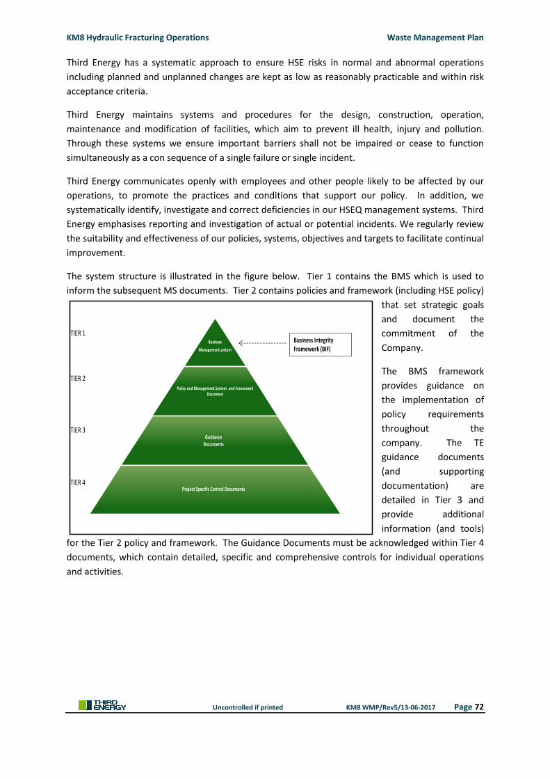
KM8 Hydraulic Fracturing Operations Waste Management Plan
Uncontrolled if printed KM8 WMP/Rev5/13-06-2017 Page 72
Third Energy has a systematic approach to ensure HSE risks in normal and abnormal operations
including planned and unplanned changes are kept as low as reasonably practicable and within risk
acceptance criteria.
Third Energy maintains systems and procedures for the design, construction, operation,
maintenance and modification of facilities, which aim to prevent ill health, injury and pollution.
Through these systems we ensure important barriers shall not be impaired or cease to function
simultaneously as a con sequence of a single failure or single incident.
Third Energy communicates openly with employees and other people likely to be affected by our
operations, to promote the practices and conditions that support our policy. In addition, we
systematically identify, investigate and correct deficiencies in our HSEQ management systems. Third
Energy emphasises reporting and investigation of actual or potential incidents. We regularly review
the suitability and effectiveness of our policies, systems, objectives and targets to facilitate continual
improvement.
The system structure is illustrated in the figure below. Tier 1 contains the BMS which is used to
inform the subsequent MS documents. Tier 2 contains policies and framework (including HSE policy)
that set strategic goals
and document the
commitment of the
Company.
The BMS framework
provides guidance on
the implementation of
policy requirements
throughout the
company. The TE
guidance documents
(and supporting
documentation) are
detailed in Tier 3 and
provide additional
information (and tools)
for the Tier 2 policy and framework. The Guidance Documents must be acknowledged within Tier 4
documents, which contain detailed, specific and comprehensive controls for individual operations
and activities.
Business
Management system
Policy and Management System and Framework Document
Guidance Documents
Project Specific Control Documents
TIER 1
TIER 2
TIER 3
TIER 4
Business Integrity Framework (BIF)

KM8 Hydraulic Fracturing Operations Waste Management Plan
Uncontrolled if printed KM8 WMP/Rev5/13-06-2017 Page 73
**This page has been intentionally left blank**

KM8 Hydraulic Fracturing Operations Waste Management Plan
Uncontrolled if printed KM8 WMP/Rev5/13-06-2017 Page 74
APPENDIX 3 – ROLES AND RESPONSIBILITES

KM8 Hydraulic Fracturing Operations Waste Management Plan
Uncontrolled if printed KM8 WMP/Rev5/13-06-2017 Page 75
**This page has been intentionally left blank**
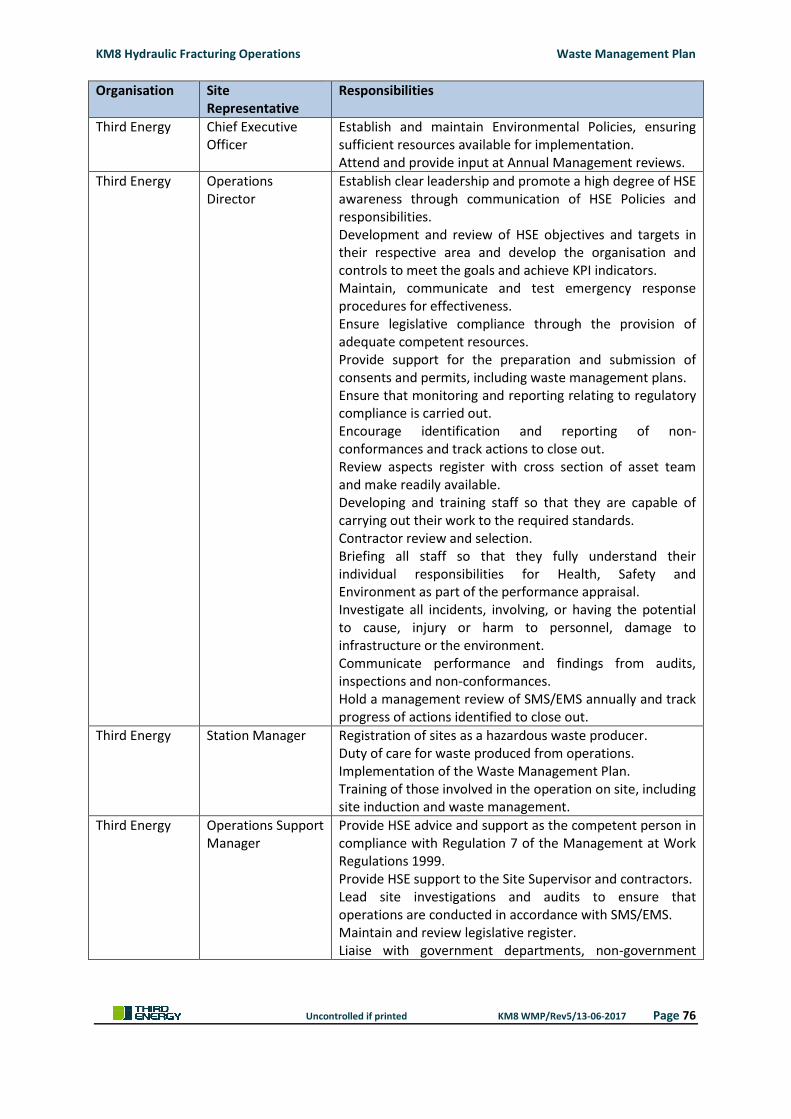
KM8 Hydraulic Fracturing Operations Waste Management Plan
Uncontrolled if printed KM8 WMP/Rev5/13-06-2017 Page 76
Organisation Site Representative
Responsibilities
Third Energy Chief Executive Officer
Establish and maintain Environmental Policies, ensuring sufficient resources available for implementation. Attend and provide input at Annual Management reviews.
Third Energy Operations Director
Establish clear leadership and promote a high degree of HSE awareness through communication of HSE Policies and responsibilities. Development and review of HSE objectives and targets in their respective area and develop the organisation and controls to meet the goals and achieve KPI indicators. Maintain, communicate and test emergency response procedures for effectiveness. Ensure legislative compliance through the provision of adequate competent resources. Provide support for the preparation and submission of consents and permits, including waste management plans. Ensure that monitoring and reporting relating to regulatory compliance is carried out. Encourage identification and reporting of non-conformances and track actions to close out. Review aspects register with cross section of asset team and make readily available. Developing and training staff so that they are capable of carrying out their work to the required standards. Contractor review and selection. Briefing all staff so that they fully understand their individual responsibilities for Health, Safety and Environment as part of the performance appraisal. Investigate all incidents, involving, or having the potential to cause, injury or harm to personnel, damage to infrastructure or the environment. Communicate performance and findings from audits, inspections and non-conformances. Hold a management review of SMS/EMS annually and track progress of actions identified to close out.
Third Energy Station Manager Registration of sites as a hazardous waste producer. Duty of care for waste produced from operations. Implementation of the Waste Management Plan. Training of those involved in the operation on site, including site induction and waste management.
Third Energy Operations Support Manager
Provide HSE advice and support as the competent person in compliance with Regulation 7 of the Management at Work Regulations 1999. Provide HSE support to the Site Supervisor and contractors. Lead site investigations and audits to ensure that operations are conducted in accordance with SMS/EMS. Maintain and review legislative register. Liaise with government departments, non-government
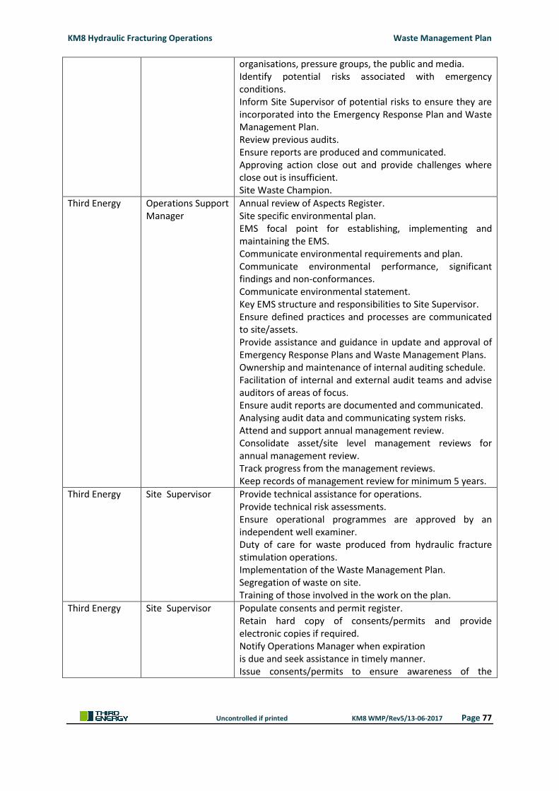
KM8 Hydraulic Fracturing Operations Waste Management Plan
Uncontrolled if printed KM8 WMP/Rev5/13-06-2017 Page 77
organisations, pressure groups, the public and media. Identify potential risks associated with emergency conditions. Inform Site Supervisor of potential risks to ensure they are incorporated into the Emergency Response Plan and Waste Management Plan. Review previous audits. Ensure reports are produced and communicated. Approving action close out and provide challenges where close out is insufficient. Site Waste Champion.
Third Energy Operations Support Manager
Annual review of Aspects Register. Site specific environmental plan. EMS focal point for establishing, implementing and maintaining the EMS. Communicate environmental requirements and plan. Communicate environmental performance, significant findings and non-conformances. Communicate environmental statement. Key EMS structure and responsibilities to Site Supervisor. Ensure defined practices and processes are communicated to site/assets. Provide assistance and guidance in update and approval of Emergency Response Plans and Waste Management Plans. Ownership and maintenance of internal auditing schedule. Facilitation of internal and external audit teams and advise auditors of areas of focus. Ensure audit reports are documented and communicated. Analysing audit data and communicating system risks. Attend and support annual management review. Consolidate asset/site level management reviews for annual management review. Track progress from the management reviews. Keep records of management review for minimum 5 years.
Third Energy Site Supervisor Provide technical assistance for operations. Provide technical risk assessments. Ensure operational programmes are approved by an independent well examiner. Duty of care for waste produced from hydraulic fracture stimulation operations. Implementation of the Waste Management Plan. Segregation of waste on site. Training of those involved in the work on the plan.
Third Energy Site Supervisor Populate consents and permit register. Retain hard copy of consents/permits and provide electronic copies if required. Notify Operations Manager when expiration is due and seek assistance in timely manner. Issue consents/permits to ensure awareness of the
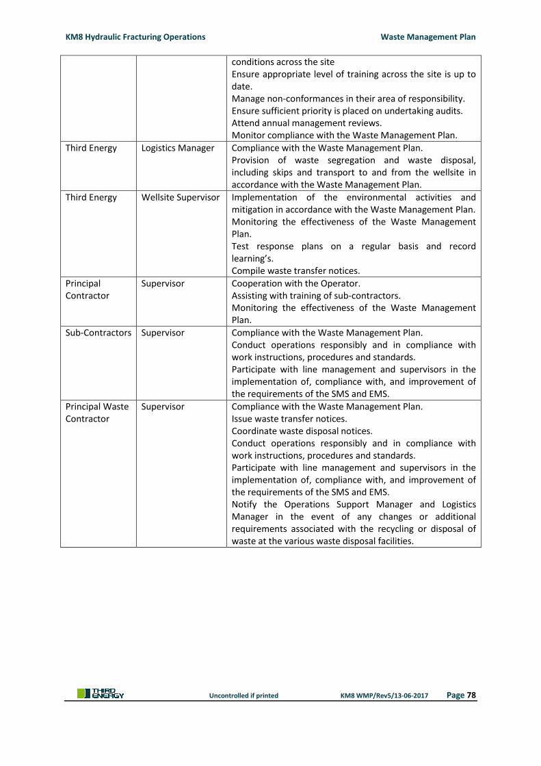
KM8 Hydraulic Fracturing Operations Waste Management Plan
Uncontrolled if printed KM8 WMP/Rev5/13-06-2017 Page 78
conditions across the site Ensure appropriate level of training across the site is up to date. Manage non-conformances in their area of responsibility. Ensure sufficient priority is placed on undertaking audits. Attend annual management reviews. Monitor compliance with the Waste Management Plan.
Third Energy Logistics Manager Compliance with the Waste Management Plan. Provision of waste segregation and waste disposal, including skips and transport to and from the wellsite in accordance with the Waste Management Plan.
Third Energy Wellsite Supervisor Implementation of the environmental activities and mitigation in accordance with the Waste Management Plan. Monitoring the effectiveness of the Waste Management Plan. Test response plans on a regular basis and record learning’s. Compile waste transfer notices.
Principal Contractor
Supervisor
Cooperation with the Operator. Assisting with training of sub-contractors. Monitoring the effectiveness of the Waste Management Plan.
Sub-Contractors Supervisor Compliance with the Waste Management Plan. Conduct operations responsibly and in compliance with work instructions, procedures and standards. Participate with line management and supervisors in the implementation of, compliance with, and improvement of the requirements of the SMS and EMS.
Principal Waste Contractor
Supervisor Compliance with the Waste Management Plan. Issue waste transfer notices. Coordinate waste disposal notices. Conduct operations responsibly and in compliance with work instructions, procedures and standards. Participate with line management and supervisors in the implementation of, compliance with, and improvement of the requirements of the SMS and EMS. Notify the Operations Support Manager and Logistics Manager in the event of any changes or additional requirements associated with the recycling or disposal of waste at the various waste disposal facilities.

KM8 Hydraulic Fracturing Operations Waste Management Plan
Uncontrolled if printed KM8 WMP/Rev5/13-06-2017 Page 79
**This page has been intentionally left blank**

KM8 Hydraulic Fracturing Operations Waste Management Plan
Uncontrolled if printed KM8 WMP/Rev5/13-06-2017 Page 80
APPENDIX 4 – CHEMICAL INVENTORY

KM8 Hydraulic Fracturing Operations Waste Management Plan
Uncontrolled if printed KM8 WMP/Rev5/13-06-2017 Page 81
**This page has been intentionally left blank**
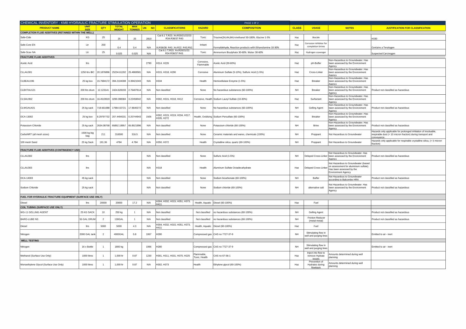
PAGE 1 0F 2
PRODUCT NAMEUNIT
SIZEQTY
TOTAL
WEIGHT
MAX
TONNESUN NO CLASSIFICATIONS HAZARD COMPOSITION CLASS USAGE NOTES JUSTIFICATION FOR CLASSIFICATION
COMPLETION FLUID ADDITIVES (RETAINED WITHIN THE WELL)
Safe-Cide KG 2525 25 2810
Cat 6.1 T;R23. Xn;R20/21/22/23
R34.R36/37 R43Toxic Triazine(2H,4H,6H)-triethanol 50-100%. Glycine 1-5% Haz Biocide
H330
Safe-Core EN Ltr 2000.4 0.4 N/A Xi;R36/38. R43. Xn;R22. R43,R52.
IrritantFormaldehyde, Reaction products with Ethanolamine 10-30%
HazCorrosion inhibitor for
completion brines Contains a Teratogen
Safe-Scav NA Ltr 250.025 0.025 N/A
Cat 6.1 T;R23. Xn;R20/21/22.
R34.R36/37 R43.Toxic Ammonium Bisulphate 30-60%. Water 30-60% Haz Hydrogen scavenger Suspected Carcinogen
Acetic Acid ltrs 2790 H314, H226Corrosive,
FlammableAcetic Acid (30-60%) Haz pH-Buffer
Non-Hazardous to Groundwater. Has
been assessed by the Environment
Agency
CLLAU301 1250 ltrs IBC 20.1876896 25234.61202 25.4869581 N/A H315, H318, H290 Corrosive Aluminum Sulfate (5-10%), Sulfuric Acid (1-5%) Haz Cross-Linker
Non-Hazardous to Groundwater. Has
been assessed by the Environment
Agency
CLBEAU196 25 kg box 15.7684172 394.2104308 0.39421043 N/A H334 Health Hemicellulase Enzyme (1-5%) Haz Breaker
Non-Hazardous to Groundwater. Has
been assessed by the Environment
Agency
CLBXTAU121 200 ltrs drum 12.123141 2424.628193 2.76407614 N/A Not classified None No hazardous substances (60-100%) NH Breaker
Non-Hazardous to Groundwater. Has
been assessed by the Environment
Agency
Product not classified as hazardous
CLSAU352 200 ltrs drum 16.4519919 3290.398384 3.22459042 N/A H302, H315, H318, H412 Corrosive, Health Sodium Lauryl Sulfate (10-30%) Haz Surfactant
Non-Hazardous to Groundwater. Has
been assessed by the Environment
Agency
CLWGAU421 25 kg sack 718.561088 17964.02721 17.9640272 N/A Not classified None No hazardous substances (60-100%) NH Gelling Agent
Non-Hazardous to Groundwater. Has
been assessed by the Environment
Agency
Product not classified as hazardous
DCA-13002 25 kg box 8.29797732 207.4494331 0.20744943 1505H302, H315, H319, H334, H317,
H335, H272Health, Oxidising Sodium Persulfate (60-100%) Haz Breaker
Non-Hazardous to Groundwater. Has
been assessed by the Environment
Agency
Potassium Chloride 25 kg sack 2634.08758 65852.18957 65.8521896 N/A Not classified None Potassium chloride (60-100%) NH Brine
Non-Hazardous to Groundwater. Has
been assessed by the Environment
Agency
Product not classified as hazardous
CarboNRT (all mesh sizes)1500 kg big
bag211 316500 316.5 N/A Not classified None Ceramic materials and wares, chemicals (100%) NH Proppant Not Hazardous to Groundwater
Hazards only applicable for prolonged inhilation of insoluable,
respirable dust (< 10 micron fraction) during transport and
conveyance.
100 mesh Sand 25 kg Sack 191.36 4784 4.784 N/A H350, H372 Health Crystalline silica, quartz (60-100%) NH Proppant Not Hazardous to GroundwaterHazards only applicable for respirable crystalline silica, (< 5 micron
fraction)
CLLAU302 ltrs N/A Not classified None Sulfuric Acid (1-5%) NH Delayed Cross-Linker
Not Hazardous to Groundwater. Has
been assessed by the Environment
Agency
Product not classified as hazardous
CLLAU303 ltrs N/A H318 Health Aluminum Sulfate Octadecahydrate Haz Delayed Cross-Linker
Not Hazardous to Groundwater (based
on assessment for aluminium sulfate).
Has been assessed by the
Environment Agency
DCA-14003 45 kg sack N/A Not classified None Sodium bicarbonate (60-100%) NH BufferNot Hazardous to Groundwater
according to Balcombe HRAProduct not classified as hazardous
Sodium Chloride 25 kg sack N/A Not classified None Sodium chloride (60-100%) NH alternative salt
Not Hazardous to Groundwater. Has
been assessed by the Environment
Agency
Product not classified as hazardous
Diesel ltrs 20000 20000 17.2 N/AH304, H332, H315, H351, H373,
H411Health, Aquatic Diesel (60-100%) Haz Fuel
WG-11 GELLING AGENT 25 KG SACK 10 250 kg 1 N/A Not classified Not classified no hazardous substances (60-100%) NH Gelling Agent Product not classified as hazardous
BARO-LUBE NS 55 GAL DRUM 2 130GAL 1 N/A Not classified Not classified no hazardous substances (60-100%) NH Friction Reducer
(metal-metal)Product not classified as hazardous
Diesel ltrs 5000 5000 4.3 N/AH304, H332, H315, H351, H373,
H411Health, Aquatic Diesel (60-100%) Haz Fuel
Nitrogen 2000 GAL tank 2 4000GAL 5.8 1067 H280 Compressed gas CAS no 7727-37-9 NHStimulating flow in
well and purging linesEmitted to air - inert
Nitrogen 16 x Bottle 1 1800 kg 1066 H280 Compressed gas CAS no 7727-37-9 NHStimulating flow in
well and purging linesEmitted to air - inert
Methanol (Surface Use Only) 1000 litres 1 1,000 ltr 0.87 1230 H301, H311, H331, H370, H225Flammable,
Toxic, HealthCAS no 67-56-1 Haz
Inject into flow to
remove Hydrate
issues
Amounts determined during well
planning
Monoethylene Glycol (Surface Use Only) 1000 litres 1 1,000 ltr 0.87 N/A H302, H373 Health Ethylene glycol (60-100%) Haz
Prevention of
Hydrates during
flowback
Amounts determined during well
planning
CHEMICAL INVENTORY - KM8 HYDRAULIC FRACTURE STIMULATION OPERATION
FRACTURE FLUID ADDITIVES
COIL TUBING (SURFACE USE ONLY)
WELL TESTING
FUEL FOR HYDRAULIC FRACTURE EQUIPMENT (SURFACE USE ONLY)
FRACTURE FLUID ADDITIVES (CONTINGENCY USE)
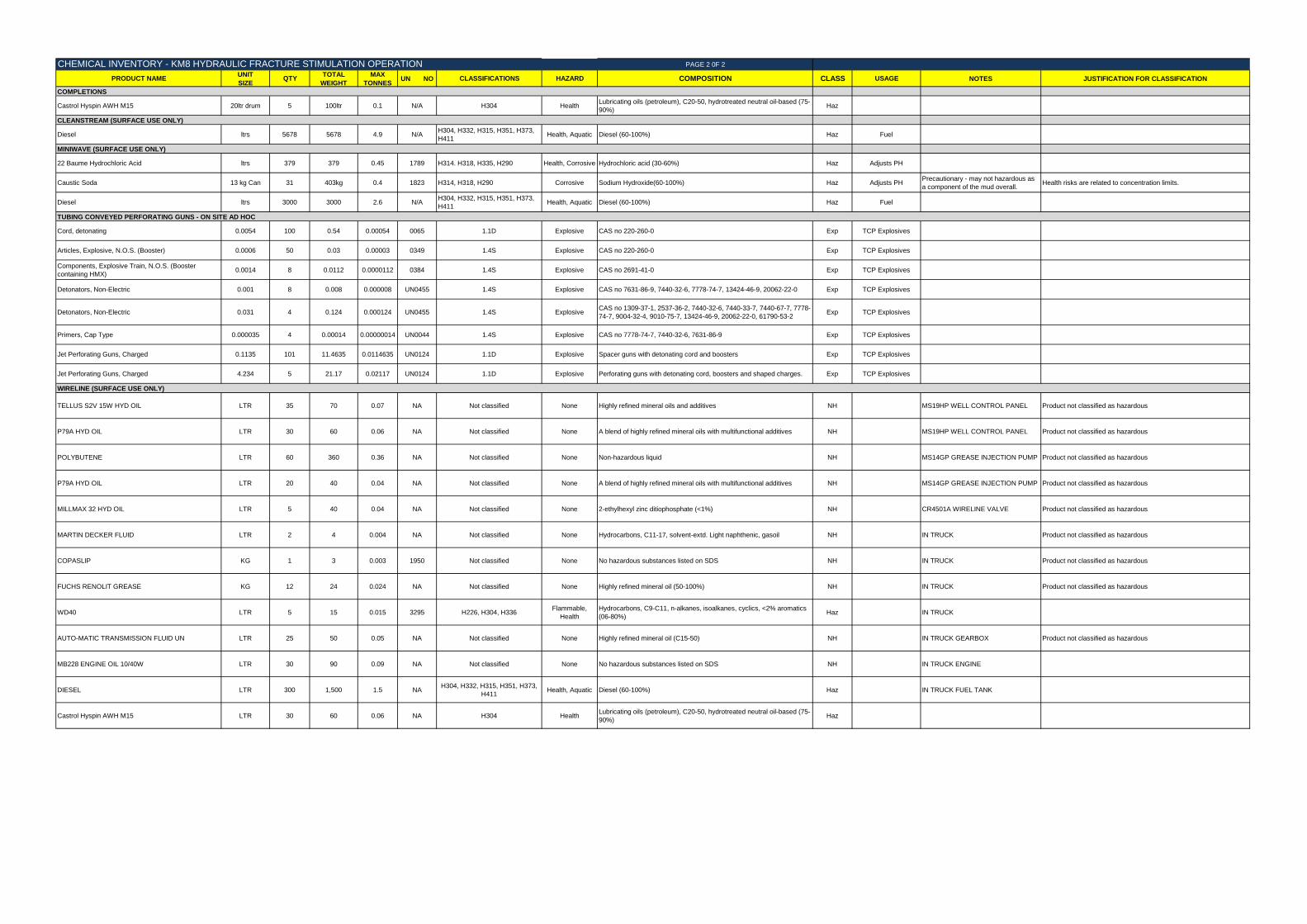
PAGE 2 0F 2
PRODUCT NAMEUNIT
SIZEQTY
TOTAL
WEIGHT
MAX
TONNESUN NO CLASSIFICATIONS HAZARD COMPOSITION CLASS USAGE NOTES JUSTIFICATION FOR CLASSIFICATION
Castrol Hyspin AWH M15 20ltr drum 5 100ltr 0.1 N/A H304 HealthLubricating oils (petroleum), C20-50, hydrotreated neutral oil-based (75-
90%)Haz
Diesel ltrs 5678 5678 4.9 N/AH304, H332, H315, H351, H373,
H411Health, Aquatic Diesel (60-100%) Haz Fuel
22 Baume Hydrochloric Acid ltrs 379 379 0.45 1789 H314. H318, H335, H290 Health, Corrosive Hydrochloric acid (30-60%) Haz Adjusts PH
Caustic Soda 13 kg Can 31 403kg 0.4 1823 H314, H318, H290 Corrosive Sodium Hydroxide(60-100%) Haz Adjusts PHPrecautionary - may not hazardous as
a component of the mud overall.Health risks are related to concentration limits.
Diesel ltrs 3000 3000 2.6 N/AH304, H332, H315, H351, H373,
H411Health, Aquatic Diesel (60-100%) Haz Fuel
Cord, detonating 0.0054 100 0.54 0.00054 0065 1.1D Explosive CAS no 220-260-0 Exp TCP Explosives
Articles, Explosive, N.O.S. (Booster) 0.0006 50 0.03 0.00003 0349 1.4S Explosive CAS no 220-260-0 Exp TCP Explosives
Components, Explosive Train, N.O.S. (Booster
containing HMX)0.0014 8 0.0112 0.0000112 0384 1.4S Explosive CAS no 2691-41-0 Exp TCP Explosives
Detonators, Non-Electric 0.001 8 0.008 0.000008 UN0455 1.4S Explosive CAS no 7631-86-9, 7440-32-6, 7778-74-7, 13424-46-9, 20062-22-0 Exp TCP Explosives
Detonators, Non-Electric 0.031 4 0.124 0.000124 UN0455 1.4S ExplosiveCAS no 1309-37-1, 2537-36-2, 7440-32-6, 7440-33-7, 7440-67-7, 7778-
74-7, 9004-32-4, 9010-75-7, 13424-46-9, 20062-22-0, 61790-53-2Exp TCP Explosives
Primers, Cap Type 0.000035 4 0.00014 0.00000014 UN0044 1.4S Explosive CAS no 7778-74-7, 7440-32-6, 7631-86-9 Exp TCP Explosives
Jet Perforating Guns, Charged 0.1135 101 11.4635 0.0114635 UN0124 1.1D Explosive Spacer guns with detonating cord and boosters Exp TCP Explosives
Jet Perforating Guns, Charged 4.234 5 21.17 0.02117 UN0124 1.1D Explosive Perforating guns with detonating cord, boosters and shaped charges. Exp TCP Explosives
TELLUS S2V 15W HYD OIL LTR 35 70 0.07 NA Not classified None Highly refined mineral oils and additives NH MS19HP WELL CONTROL PANEL Product not classified as hazardous
P79A HYD OIL LTR 30 60 0.06 NA Not classified None A blend of highly refined mineral oils with multifunctional additives NH MS19HP WELL CONTROL PANEL Product not classified as hazardous
POLYBUTENE LTR 60 360 0.36 NA Not classified None Non-hazardous liquid NH MS14GP GREASE INJECTION PUMP Product not classified as hazardous
P79A HYD OIL LTR 20 40 0.04 NA Not classified None A blend of highly refined mineral oils with multifunctional additives NH MS14GP GREASE INJECTION PUMP Product not classified as hazardous
MILLMAX 32 HYD OIL LTR 5 40 0.04 NA Not classified None 2-ethylhexyl zinc ditiophosphate (<1%) NH CR4501A WIRELINE VALVE Product not classified as hazardous
MARTIN DECKER FLUID LTR 2 4 0.004 NA Not classified None Hydrocarbons, C11-17, solvent-extd. Light naphthenic, gasoil NH IN TRUCK Product not classified as hazardous
COPASLIP KG 1 3 0.003 1950 Not classified None No hazardous substances listed on SDS NH IN TRUCK Product not classified as hazardous
FUCHS RENOLIT GREASE KG 12 24 0.024 NA Not classified None Highly refined mineral oil (50-100%) NH IN TRUCK Product not classified as hazardous
WD40 LTR 5 15 0.015 3295 H226, H304, H336Flammable,
Health
Hydrocarbons, C9-C11, n-alkanes, isoalkanes, cyclics, <2% aromatics
(06-80%)Haz IN TRUCK
AUTO-MATIC TRANSMISSION FLUID UN LTR 25 50 0.05 NA Not classified None Highly refined mineral oil (C15-50) NH IN TRUCK GEARBOX Product not classified as hazardous
MB228 ENGINE OIL 10/40W LTR 30 90 0.09 NA Not classified None No hazardous substances listed on SDS NH IN TRUCK ENGINE
DIESEL LTR 300 1,500 1.5 NAH304, H332, H315, H351, H373,
H411Health, Aquatic Diesel (60-100%) Haz IN TRUCK FUEL TANK
Castrol Hyspin AWH M15 LTR 30 60 0.06 NA H304 HealthLubricating oils (petroleum), C20-50, hydrotreated neutral oil-based (75-
90%)Haz
WIRELINE (SURFACE USE ONLY)
CHEMICAL INVENTORY - KM8 HYDRAULIC FRACTURE STIMULATION OPERATION
TUBING CONVEYED PERFORATING GUNS - ON SITE AD HOC
COMPLETIONS
MINIWAVE (SURFACE USE ONLY)
CLEANSTREAM (SURFACE USE ONLY)

KM8 Hydraulic Fracturing Operations Waste Management Plan
Uncontrolled if printed KM8 WMP/Rev5/13-06-2017 Page 82
APPENDIX 5 – HYDRAULIC FRACTURE FLUID DISCLOSURE

KM8 Hydraulic Fracturing Operations Waste Management Plan
Uncontrolled if printed KM8 WMP/Rev5/13-06-2017 Page 83
**This page has been intentionally left blank**

Chemical Substance CAS Number
Has thesubstancepreviouslybeenconsidered byJAGDAG?
ClassificationunderGroundwaterRegulations 1998
Is significant newdata or evidenceavailable sinceoriginaldetermination?
Is theresufficientinformation toundertake anassessment ofthe substance?
Is substanceclassed as aRadioactiveSubstance?
Does substance meet the testof being a Persistent,Bioaccumulative and Toxic(PBT) as defined in theREACH regulation and TGD?
Does the substance meetcriteria for high B and highT under REACH / TGD andCLP; and additionally meetthe test of high persistencein groundwater defined inParagraph 2.1.2?;
Is substanceclassed as vPvBunder REACH orparagraph2.1.3?;
Is thesubstanceclassed asCMT underCLP?;
Is the substancevery acutely toxic toaquatic biota?
Is thesubstancepersistentandpotentiallyvery toxic tohumans? Conclusion
Are there anyapplicablehazardousbreakdownproducts orintrinisicimpurities?
Acetic acid 64-19-7 No N/A N/A Yes No
No. Biodegradability >95% in28d1. Log Pow -0.171. NOEC3.058 mg/L (freshwater)2 No No No
No - NOEC 3.058mg/L (freshwater)2 No Non-hazardous No
Aluminium sulfate 10043-01-3 Yes
List 2 (Non-hazardouspollutant) No Yes No
PBT not applicable toinorganic substances. N/A (inorganic) N/A (inorganic) No
No - NOEC 0.026 inFry, 3.8 inCeridaphnia1 (figuresbased on dissolvedAl). No Non-hazardous No
Aluminium sulfateoctahydrate 7784-31-8 No N/A N/A Yes No
PBT not applicable toinorganic substances. N/A (inorganic) N/A (inorganic) No No data No
Non-hazardous(based onassessment foraluminium sulfate) No
Hemicellulase enzyme 9012-54-8 No N/A N/A Yes No
No. Biogradability 129% in28d1. Log Pow -2.951. NOEC45.5 (a.i.) mg/L in freshwater2 No No No No No Non-hazardous No
Potassium chloride 7447-40-7 No N/A N/A Yes NoPBT not applicable toinorganic substances. N/A (inorganic) N/A (inorganic) No
No - NOEC 500mg/L2
in fathead minnows No Non-hazardous No
Sodium chloride 7647-14-5 No N/A N/A Yes NoPBT not applicable toinorganic substances. N/A (inorganic) N/A (inorganic) No
No - NOEC 252 mg/Lfish, 292-584 mg/Lmicroorganisms, 314mg/L daphnia1 No Non-hazardous No
Sodium lauryl sulfate 151-21-3 No N/A N/A Yes No
No. Biogradability 95% in28d1. Log Pow -2.031. NOEC3.8 fish and 0.88invertebrates1 No No No No No Non-hazardous No
Sodium persulfate 7775-27-1 No N/A N/A Yes NoPBT not applicable toinorganic substances. N/A (inorganic) N/A (inorganic) No
No - NOEC 91.7 fishfreshwater2 No Non-hazardous No
Sulfuric acid 7664-93-9 No N/A N/A Yes NoPBT not applicable toinorganic substances. N/A (inorganic) N/A (inorganic) No
No - NOEC 0.31 (fish)NOEC 6.61(microorganisms)NOEC 0.15(invertebrates)1 No Non-hazardous No
1Data from SDS2Data from REACH dossier
High persistence High bioaccumulation High toxicityHalf-life in marine water is > 60 days BCF > 2000 NOEC for marine or freshwater species < 0.01 mg/LHalf-life in fresh water is > 40 days Log Pow > 4.5 Has hazard class Muta. 1A, Muta. 1B, Muta 2, Carc 1A, Carc 1B, Repr 1A or Repr 1BHalf-life in marine sediments > 180 days Has hazard class Acute Tox 1, Actute Tox 2, Acute Tox 3, STOT SE 1 or STOT RE1Half-life in fresh water sediments is > 120 daysHalf-life in soil is > 120 days
Note: This table sets out the groundwater hazard assessment for substances in the hydraulic fracturing fluid. It does not include substances which have been preivoulsy assessed as non-hazardous by the Enviornment Agency (e.g. crystalling silica, quartz and sodium bicarbonate). All chemical substancedata is consistent wtih Safety Data Sheets.
Substance assessment based on the Joint Agencies Groundwater Directive Advisory Group (JAGDAG) Methodology
1
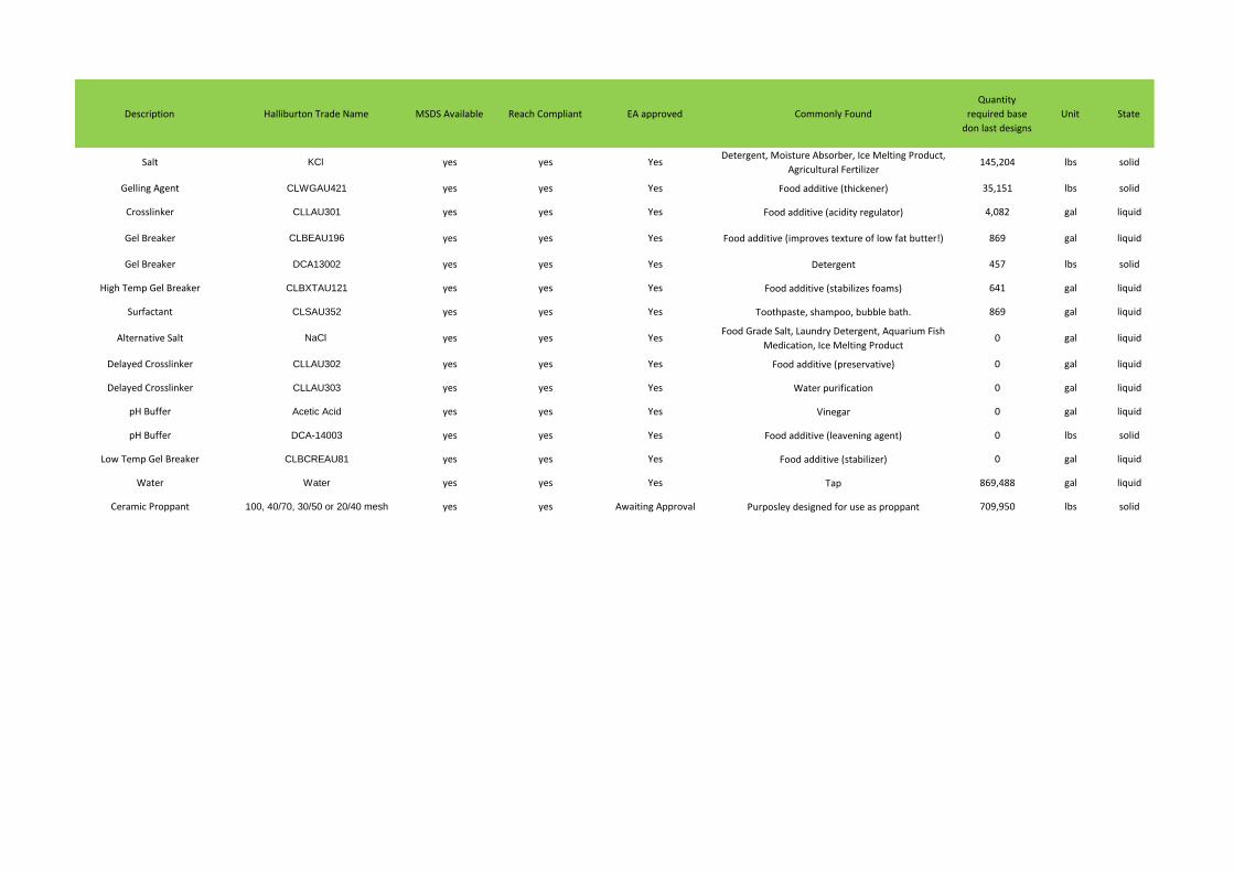
Description Halliburton Trade Name MSDS Available Reach Compliant EA approved Commonly Found
Quantity
required base
don last designs
Unit State
Salt KCl yes yes YesDetergent, Moisture Absorber, Ice Melting Product,
Agricultural Fertilizer145,204 lbs solid
Gelling Agent CLWGAU421 yes yes Yes Food additive (thickener) 35,151 lbs solid
Crosslinker CLLAU301 yes yes Yes Food additive (acidity regulator) 4,082 gal liquid
Gel Breaker CLBEAU196 yes yes Yes Food additive (improves texture of low fat butter!) 869 gal liquid
Gel Breaker DCA13002 yes yes Yes Detergent 457 lbs solid
High Temp Gel Breaker CLBXTAU121 yes yes Yes Food additive (stabilizes foams) 641 gal liquid
Surfactant CLSAU352 yes yes Yes Toothpaste, shampoo, bubble bath. 869 gal liquid
Alternative Salt NaCl yes yes YesFood Grade Salt, Laundry Detergent, Aquarium Fish
Medication, Ice Melting Product0 gal liquid
Delayed Crosslinker CLLAU302 yes yes Yes Food additive (preservative) 0 gal liquid
Delayed Crosslinker CLLAU303 yes yes Yes Water purification 0 gal liquid
pH Buffer Acetic Acid yes yes Yes Vinegar 0 gal liquid
pH Buffer DCA-14003 yes yes Yes Food additive (leavening agent) 0 lbs solid
Low Temp Gel Breaker CLBCREAU81 yes yes Yes Food additive (stabilizer) 0 gal liquid
Water Water yes yes Yes Tap 869,488 gal liquid
Ceramic Proppant 100, 40/70, 30/50 or 20/40 mesh yes yes Awaiting Approval Purposley designed for use as proppant 709,950 lbs solid
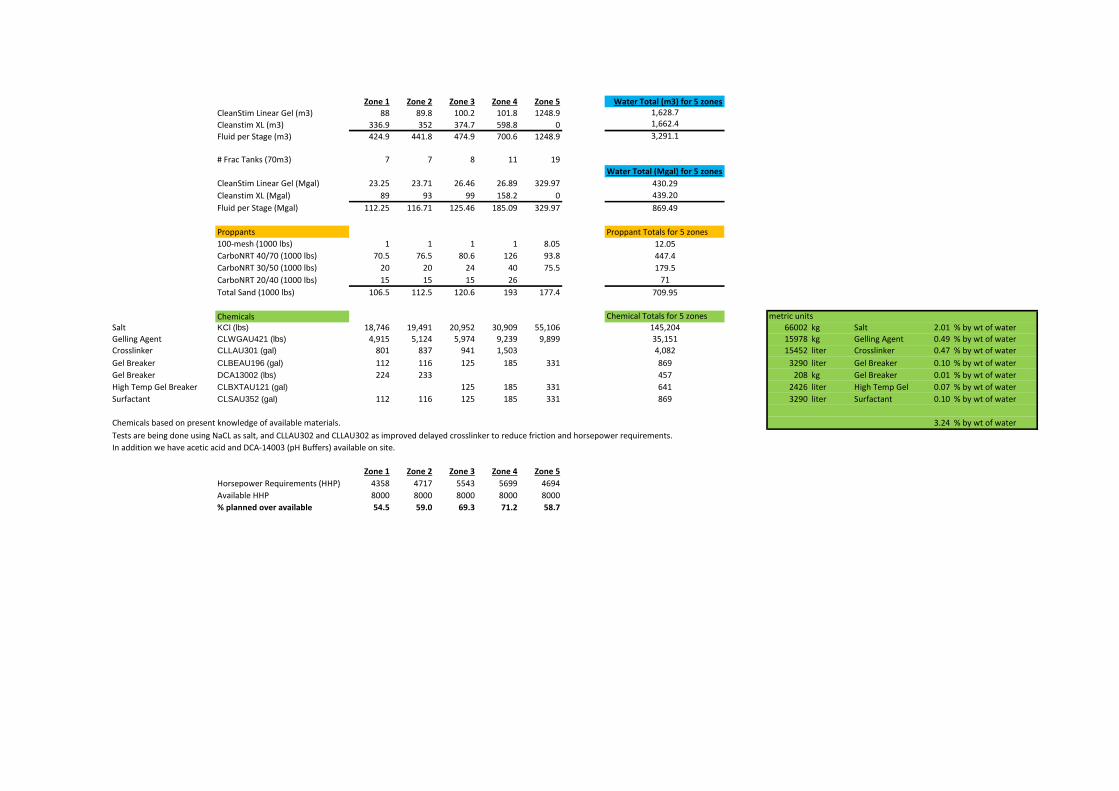
Zone 1 Zone 2 Zone 3 Zone 4 Zone 5 Water Total (m3) for 5 zones
CleanStim Linear Gel (m3) 88 89.8 100.2 101.8 1248.9 1,628.7
Cleanstim XL (m3) 336.9 352 374.7 598.8 0 1,662.4
Fluid per Stage (m3) 424.9 441.8 474.9 700.6 1248.9 3,291.1
# Frac Tanks (70m3) 7 7 8 11 19
Water Total (Mgal) for 5 zones
CleanStim Linear Gel (Mgal) 23.25 23.71 26.46 26.89 329.97 430.29
Cleanstim XL (Mgal) 89 93 99 158.2 0 439.20
Fluid per Stage (Mgal) 112.25 116.71 125.46 185.09 329.97 869.49
Proppants Proppant Totals for 5 zones
100-mesh (1000 lbs) 1 1 1 1 8.05 12.05
CarboNRT 40/70 (1000 lbs) 70.5 76.5 80.6 126 93.8 447.4
CarboNRT 30/50 (1000 lbs) 20 20 24 40 75.5 179.5
CarboNRT 20/40 (1000 lbs) 15 15 15 26 71
Total Sand (1000 lbs) 106.5 112.5 120.6 193 177.4 709.95
Chemicals Chemical Totals for 5 zones metric units
Salt KCl (lbs) 18,746 19,491 20,952 30,909 55,106 145,204 66002 kg Salt 2.01 % by wt of water
Gelling Agent CLWGAU421 (lbs) 4,915 5,124 5,974 9,239 9,899 35,151 15978 kg Gelling Agent 0.49 % by wt of water
Crosslinker CLLAU301 (gal) 801 837 941 1,503 4,082 15452 liter Crosslinker 0.47 % by wt of water
Gel Breaker CLBEAU196 (gal) 112 116 125 185 331 869 3290 liter Gel Breaker 0.10 % by wt of water
Gel Breaker DCA13002 (lbs) 224 233 457 208 kg Gel Breaker 0.01 % by wt of water
High Temp Gel Breaker CLBXTAU121 (gal) 125 185 331 641 2426 liter High Temp Gel Breaker0.07 % by wt of water
Surfactant CLSAU352 (gal) 112 116 125 185 331 869 3290 liter Surfactant 0.10 % by wt of water
Chemicals based on present knowledge of available materials. 3.24 % by wt of water
Tests are being done using NaCL as salt, and CLLAU302 and CLLAU302 as improved delayed crosslinker to reduce friction and horsepower requirements.
In addition we have acetic acid and DCA-14003 (pH Buffers) available on site.
Zone 1 Zone 2 Zone 3 Zone 4 Zone 5
Horsepower Requirements (HHP) 4358 4717 5543 5699 4694
Available HHP 8000 8000 8000 8000 8000
% planned over available 54.5 59.0 69.3 71.2 58.7

Breakdown/Stepdown/ Displ Minifrac Volume
per Mgal Unit
1 14.2 Mgal
167.0 lbs/Mgal KCl 167.0 2378 lbs
20.0 lbs/Mgal CLWGAU421 20.0 285 lbs
1.0 gal/Mgal CLBEAU196 1.00 14 gal
2.0 lbs/Mgal DCA13002 2.00 28 lbs
1.0 gal/Mgal CLSAU352 1.00 14 gal
Pad/Carrier Mini/Mainfrac Volume
per Mgal Unit
1.0 89.0 Mgal
167 lbs/Mgal KCl 167.0 14863 lbs
50.0 lbs/Mgal CLWGAU421 50.0 4450 lbs
9.0 gal/Mgal CLLAU301 9.0 801 gal
1.0 gal/Mgal CLBEAU196 1.00 89 gal
2.0 lbs/Mgal DCA13002 2.00 178 lbs
1.0 gal/Mgal CLSAU352 1.00 89 gal
Displacement - Mini/Mainfrac Volume
per Mgal Unit
1 9.01 Mgal
167 lbs/Mgal KCl 167.0 1505 lbs
20.0 lbs/Mgal CLWGAU421 20.0 180 lbs
1.0 gal/Mgal CLBEAU196 1.00 9 gal
2.0 lbs/Mgal DCA13002 2.00 18 lbs
1.0 gal/Mgal CLSAU352 1.00 9 gal

Breakdown/Stepdown/ Displ Minifrac Volume
per Mgal Unit
1 14.2 Mgal
167.0 lbs/Mgal KCl 167.0 2378 lbs
20.0 lbs/Mgal CLWGAU421 20.0 285 lbs
1.0 gal/Mgal CLBEAU196 1.00 14 gal
2.0 lbs/Mgal DCA13002 2.00 28 lbs
1.0 gal/Mgal CLSAU352 1.00 14 gal
Pad/Carrier Mini/Mainfrac Volume
per Mgal Unit
1.0 93.0 Mgal
167 lbs/Mgal KCl 167.0 15531 lbs
50.0 lbs/Mgal CLWGAU421 50.0 4650 lbs
9.0 gal/Mgal CLLAU301 9.0 837 gal
1.0 gal/Mgal CLBEAU196 1.00 93 gal
2.0 lbs/Mgal DCA13002 2.00 186 lbs
1.0 gal/Mgal CLSAU352 1.00 93 gal
Displacement - Mini/Mainfrac Volume
per Mgal Unit
1 9.47 Mgal
167 lbs/Mgal KCl 167.0 1582 lbs
20.0 lbs/Mgal CLWGAU421 20.0 189 lbs
1.0 gal/Mgal CLBEAU196 1.00 9 gal
2.0 lbs/Mgal DCA13002 2.00 19 lbs
1.0 gal/Mgal CLSAU352 1.00 9 gal
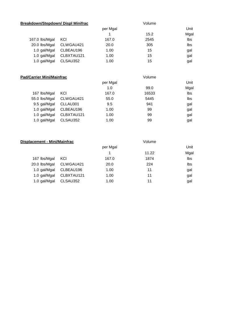
Breakdown/Stepdown/ Displ Minifrac Volume
per Mgal Unit
1 15.2 Mgal
167.0 lbs/Mgal KCl 167.0 2545 lbs
20.0 lbs/Mgal CLWGAU421 20.0 305 lbs
1.0 gal/Mgal CLBEAU196 1.00 15 gal
1.0 gal/Mgal CLBXTAU121 1.00 15 gal
1.0 gal/Mgal CLSAU352 1.00 15 gal
Pad/Carrier Mini/Mainfrac Volume
per Mgal Unit
1.0 99.0 Mgal
167 lbs/Mgal KCl 167.0 16533 lbs
55.0 lbs/Mgal CLWGAU421 55.0 5445 lbs
9.5 gal/Mgal CLLAU301 9.5 941 gal
1.0 gal/Mgal CLBEAU196 1.00 99 gal
1.0 gal/Mgal CLBXTAU121 1.00 99 gal
1.0 gal/Mgal CLSAU352 1.00 99 gal
Displacement - Mini/Mainfrac Volume
per Mgal Unit
1 11.22 Mgal
167 lbs/Mgal KCl 167.0 1874 lbs
20.0 lbs/Mgal CLWGAU421 20.0 224 lbs
1.0 gal/Mgal CLBEAU196 1.00 11 gal
1.0 gal/Mgal CLBXTAU121 1.00 11 gal
1.0 gal/Mgal CLSAU352 1.00 11 gal

Breakdown/Stepdown/ Displ Minifrac Volume
per Mgal Unit
1 15.2 Mgal
167.0 lbs/Mgal KCl 167.0 2545 lbs
20.0 lbs/Mgal CLWGAU421 20.0 305 lbs
1.0 gal/Mgal CLBEAU196 1.00 15 gal
1.0 gal/Mgal CLBXTAU121 1.00 15 gal
1.0 gal/Mgal CLSAU352 1.00 15 gal
Pad/Carrier Mini/Mainfrac Volume
per Mgal Unit
1.0 158.2 Mgal
167 lbs/Mgal KCl 167.0 26419 lbs
55.0 lbs/Mgal CLWGAU421 55.0 8701 lbs
9.5 gal/Mgal CLLAU301 9.5 1503 gal
1.0 gal/Mgal CLBEAU196 1.00 158 gal
1.0 gal/Mgal CLBXTAU121 1.00 158 gal
1.0 gal/Mgal CLSAU352 1.00 158 gal
Displacement - Mini/Mainfrac Volume
per Mgal Unit
1 11.65 Mgal
167 lbs/Mgal KCl 167.0 1945 lbs
20.0 lbs/Mgal CLWGAU421 20.0 233 lbs
1.0 gal/Mgal CLBEAU196 1.00 12 gal
1.0 gal/Mgal CLBXTAU121 1.00 12 gal
1.0 gal/Mgal CLSAU352 1.00 12 gal
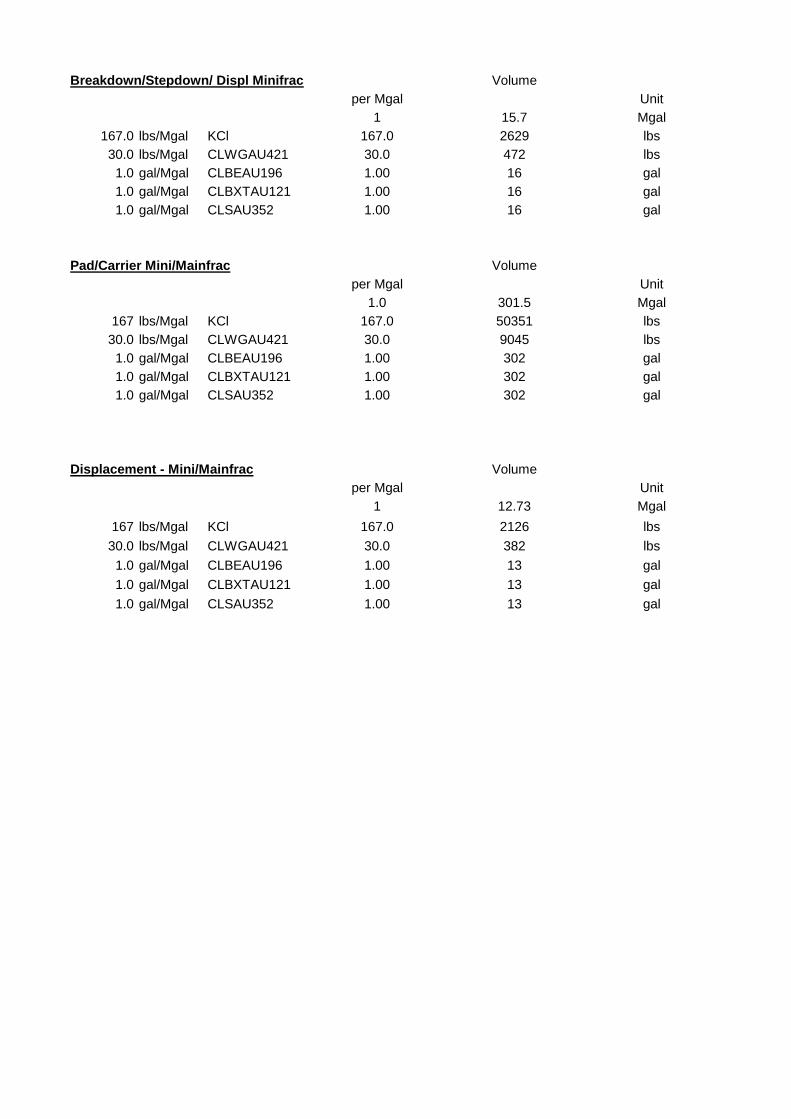
Breakdown/Stepdown/ Displ Minifrac Volume
per Mgal Unit
1 15.7 Mgal
167.0 lbs/Mgal KCl 167.0 2629 lbs
30.0 lbs/Mgal CLWGAU421 30.0 472 lbs
1.0 gal/Mgal CLBEAU196 1.00 16 gal
1.0 gal/Mgal CLBXTAU121 1.00 16 gal
1.0 gal/Mgal CLSAU352 1.00 16 gal
Pad/Carrier Mini/Mainfrac Volume
per Mgal Unit
1.0 301.5 Mgal
167 lbs/Mgal KCl 167.0 50351 lbs
30.0 lbs/Mgal CLWGAU421 30.0 9045 lbs
1.0 gal/Mgal CLBEAU196 1.00 302 gal
1.0 gal/Mgal CLBXTAU121 1.00 302 gal
1.0 gal/Mgal CLSAU352 1.00 302 gal
Displacement - Mini/Mainfrac Volume
per Mgal Unit
1 12.73 Mgal
167 lbs/Mgal KCl 167.0 2126 lbs
30.0 lbs/Mgal CLWGAU421 30.0 382 lbs
1.0 gal/Mgal CLBEAU196 1.00 13 gal
1.0 gal/Mgal CLBXTAU121 1.00 13 gal
1.0 gal/Mgal CLSAU352 1.00 13 gal
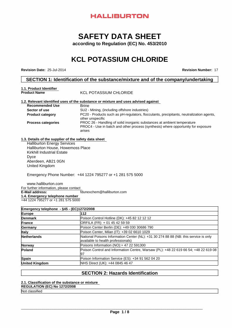
SAFETY DATA SHEETaccording to Regulation (EC) No. 453/2010
KCL POTASSIUM CHLORIDERevision Date: 25-Jul-2014 Revision Number: 17
France ORFILA (FR): + 01 45 42 59 59
KCL POTASSIUM CHLORIDE
Germany Poison Center Berlin (DE): +49 030 30686 790
1.3. Details of the supplier of the safety data sheet
Italy Poison Center, Milan (IT): +39 02 6610 1029
Recommended Use Brine
Netherlands National Poisons Information Center (NL): +31 30 274 88 88 (NB: this service is onlyavailable to health professionals)
Halliburton Energy ServicesHalliburton House, Howemoss PlaceKirkhill Industrial EstateDyceAberdeen, AB21 0GNUnited Kingdom
Emergency Phone Number: +44 1224 795277 or +1 281 575 5000
www.halliburton.com
Norway Poisons Information (NO):+ 47 22 591300
SECTION 1: Identification of the substance/mixture and of the company/undertaking
1.1. Product Identifier
Poland Poison Control and Information Centre, Warsaw (PL): +48 22 619 66 54; +48 22 619 0897
For further information, please contact
Spain Poison Information Service (ES): +34 91 562 04 20
Sector of use
E-Mail address:
United Kingdom NHS Direct (UK): +44 0845 46 47
SU2 - Mining, (including offshore industries)
1.4. Emergency telephone number
SECTION 2: Hazards Identification
+44 1224 795277 or +1 281 575 5000
Product category
2.1. Classification of the substance or mixture
PC20 - Products such as pH-regulators, flocculants, precipitants, neutralization agents,other unspecific
REGULATION (EC) No 1272/2008Not classified
Emergency telephone - §45 - (EC)1272/2008
Process categories
Europe 112
PROC 26 - Handling of solid inorganic substances at ambient temperaturePROC4 - Use in batch and other process (synthesis) where opportunity for exposurearises
_____________________________________________________________________________________________
1.2. Relevant identified uses of the substance or mixture and uses advised against
Denmark
Page 1 / 8
Poison Control Hotline (DK): +45 82 12 12 12
Product Name
_____________________________________________________________________________________________KCL POTASSIUM CHLORIDE Revision Date: 25-Jul-2014
60 - 100% Not applicable Not applicable No data available
Precautionary Statements - EU (§28, 1272/2008)Not Classified
2.2. Label Elements
Risk Phrases
For the full text of the R-phrases mentioned in this Section, see Section 16
None
Not classified
Contains
3.1. Substances Substance3.2. Mixtures Not applicable
Classification
Substances CAS Number
Not Classified
SECTION 4: First aid measures
Potassium chloride 7447-40-7
4.1. Description of first aid measures Inhalation If inhaled, remove from area to fresh air. Get medical attention if respiratory
irritation develops or if breathing becomes difficult.Eyes In case of contact, or suspected contact, immediately flush eyes with plenty of
water for at least 15 minutes and get medical attention immediately afterflushing.
Signal Word
Skin Wash with soap and water. Get medical attention if irritation persists.
None
Ingestion Do not induce vomiting. Slowly dilute with 1-2 glasses of water or milk andseek medical attention. Never give anything by mouth to an unconsciousperson.
2.3. Other Hazards
4.2. Most Important symptoms and effects, both acute and delayed
None known
May cause mild eye, skin, and respiratory irritation.
Hazard Pictograms
4.3. Indication of any immediate medical attention and special treatment needed
Hazard StatementsNot Classified
SECTION 3: Composition/information on Ingredients
Notes to Physician Treat symptomatically
Classification according to EU Directives 67/548/EEC or 1999/45/ECFor the full text of the R-phrases mentioned in this Section, see Section 16
SECTION 5: Firefighting Measures
Substances
5.1. Extinguishing media
EINECS CAS Number
Suitable Extinguishing MediaAll standard fire fighting media
PERCENT(w/w)
EECClassification
EU - CLP SubstanceClassification
REACH No.
Potassium chloride
_____________________________________________________________________________________________
231-211-8 7447-40-7
Page 2 / 8
_____________________________________________________________________________________________Revision Date: 25-Jul-2014KCL POTASSIUM CHLORIDE
UK OEL Netherlands France OEL
6.1. Personal precautions, protective equipment and emergency procedures
Avoid contact with eyes, skin, or clothing. Avoid creating or inhaling dust. Avoid breathing vapors.
Potassium chloride 7447-40-7 Not applicable 10 mg/m3 Not applicable Not applicable
6.3. Methods and material for containment and cleaning up
Hygiene MeasuresHandle in accordance with good industrial hygiene and safety practice
Substances CAS Number Germany MAK/TRK Spain Portugal Finland
Use appropriate protective equipment. Avoid creating and breathing dust.
Potassium chloride 7447-40-7 Not applicable Not applicable Not applicable Not applicable
Scoop up and remove.
Special Protective Equipment for Fire-FightersFull protective clothing and approved self-contained breathing apparatus required for fire fighting personnel.
7.2. Conditions for safe storage, including any incompatibilities
Special Exposure HazardsNot applicable.
Substances CAS Number Austria Ireland Switzerland Norway
Store in a cool, dry location. Product has a shelf life of 60 months.
Potassium chloride 7447-40-7 Not applicable Not applicable Not applicable Not applicable
See Section 8 for additional information
6.4. Reference to other sections
Substances CAS Number Italy Poland Hungary Czech Republic
SECTION 6: Accidental release measures
7.3. Specific End Use(s)
Potassium chloride 7447-40-7 Not applicable Not applicable Not applicable Not applicable
See Section 8 and 13 for additional information.
Exposure Scenario No information available
Substances CAS Number Denmark
5.2. Special hazards arising from the substance or mixture
Potassium chloride 7447-40-7 Not applicable
Other Guidelines No information available
6.2. Environmental precautions
SECTION 7: Handling and Storage
SECTION 8: Exposure Controls/Personal Protection
Derived No Effect Level (DNEL) No information available.
Prevent from entering sewers, waterways, or low areas.
Worker
8.1. Control parameters
General Population
Extinguishing media which must not be used for safety reasonsNone known.
5.3. Advice for firefighters
Exposure Limits
7.1. Precautions for Safe Handling
_____________________________________________________________________________________________
Substances
Page 3 / 8
CAS Number EU

_____________________________________________________________________________________________KCL POTASSIUM CHLORIDE Revision Date: 25-Jul-2014
SECTION 9: Physical and Chemical Properties
Vapor Density No data availableSpecific Gravity 1.99
Hand Protection
Water Solubility Soluble in water
Normal work gloves.
9.1. Information on basic physical and chemical properties
Solubility in other solvents No data available
Personal protective equipment
Partition coefficient: n-octanol/water No data available
Skin Protection
Autoignition Temperature No data available
Normal work coveralls.
Decomposition Temperature No data availableViscosity No data available
Predicted No Effect Concentration (PNEC)
Explosive Properties No information available
Eye Protection Dust proof goggles.
Oxidizing Properties No information available
No information available.
9.2. Other information
Other Precautions
Molecular Weight 74.55VOC Content (%) No data available
Eyewash fountains and safety showers must be easily accessible.
If engineering controls and work practices cannot prevent excessive exposures, the selection and proper use of personalprotective equipment should be determined by an industrial hygienist or other qualified professional based on the specificapplication of this product.
Property Values
SECTION 10: Stability and Reactivity
8.2. Exposure controls
Remarks/ - Method
10.1. Reactivity
pH:
Not applicable
9.2
10.2. Chemical Stability
Environmental Exposure Controls
Freezing Point/Range
Stable
No data available
No information available
10.3. Possibility of Hazardous Reactions
Melting Point/Range
Will Not Occur
771 °C
Engineering Controls
10.4. Conditions to Avoid
Boiling Point/Range
None anticipated
1413 °C
10.5. Incompatible Materials
Flash Point
None known.
No data available
Respiratory Protection
Evaporation rate No data available
If engineering controls and work practices cannot keep exposure below occupationalexposure limits or if exposure is unknown, wear a NIOSH certified, European StandardEN 149, AS/NZS 1715:2009, or equivalent respirator when using this product. Selectionof and instruction on using all personal protective equipment, including respirators,should be performed by an Industrial Hygienist or other qualified professional.Dust/mist respirator. (N95, P2/P3)
Use in a well ventilated area.
Vapor Pressure No data available
OdorlessPhysical State: Solid Color:
_____________________________________________________________________________________________
White to grayOdor Threshold:
Page 4 / 8
No information availableOdor:
_____________________________________________________________________________________________KCL POTASSIUM CHLORIDE Revision Date: 25-Jul-2014
Substances CASNumber
Eye damage/irritation
No data available to indicate product or components present at greater than 1% arechronic health hazards.
Inhalation
Potassium chloride 7447-40-7 May cause mild eye irritation. (rabbit) (similar substances)
May cause mild respiratory irritation.
None known.
Substances CASNumber
Skin Sensitization
SECTION 11: Toxicological Information
Potassium chloride 7447-40-7 Did not cause sensitization on laboratory animals (mouse) (similar substances)
LD50 Oral: > 5000 mg/kg (rat)
Eye Contact
Substances CASNumber
Respiratory Sensitization
Potassium chloride 7447-40-7 No information available
May cause mild eye irritation.
11.1. Information on Toxicological Effects
Toxicology data for the components
Substances CASNumber
Mutagenic Effects
Potassium chloride 7447-40-7 In vitro tests did not show mutagenic effects
Skin Contact May cause mild skin irritation.
Substances
Substances CASNumber
Carcinogenic Effects
CASNumber
LD50 Oral
Potassium chloride 7447-40-7 Did not show carcinogenic effects in animal experiments (similar substances)
LD50 Dermal LC50 Inhalation
10.6. Hazardous Decomposition Products
Acute Toxicity
Substances CASNumber
Reproductive toxicity
Potassium chloride 7447-40-7
Potassium chloride 7447-40-7 Animal testing did not show any effects on fertility. Did not show teratogenic effects in animalexperiments. (similar substances)
2600 mg/kg (Rat)2430 mg/kg (Rat)3020 mg/kg (Rat)
383 mg/kg (Mouse)1500 mg/kg (Mouse)
> 2000 mg/L (Rabbit) (similarsubstance)
No data available
Substances CASNumber
STOT - single exposure
Ingestion
Potassium chloride 7447-40-7 No significant toxicity observed in animal studies at concentration requiring classification.
May cause abdominal pain, vomiting, nausea, and diarrhea. Irritation of the mouth,throat, and stomach.
Substances
Substances CASNumber
STOT - repeated exposure
CASNumber
Skin corrosion/irritation
Potassium chloride 7447-40-7 No significant toxicity observed in animal studies at concentration requiring classification. (similarsubstances)
Potassium chloride 7447-40-7 Non-irritating to the skin (rabbit) (similar substances)
_____________________________________________________________________________________________Page 5 / 8
Chronic Effects/Carcinogenicity
_____________________________________________________________________________________________KCL POTASSIUM CHLORIDE Revision Date: 25-Jul-2014
Substances
SECTION 12: Ecological Information
12.5. Results of PBT and vPvB assessment No information available.
12.2. Persistence and degradability The methods for determining biodegradability are not applicable to inorganic substances.
12.6. Other adverse effects
CASNumber
Potassium chloride
Endocrine Disruptor InformationThis product does not contain any known or suspected endocrine disruptors
Substances CAS Number Persistence and Degradability
12.1. Toxicity
SECTION 13: Disposal Considerations
Potassium chloride 7447-40-7 The methods for determining biodegradability arenot applicable to inorganic substances.
13.1. Waste treatment methods
Ecotoxicity Effects
Disposal Method Bury in a licensed landfill according to federal, state, and local regulations. Substanceshould NOT be deposited into a sewage facility.
Contaminated Packaging Follow all applicable national or local regulations. Contaminated packaging may bedisposed of by: rendering packaging incapable of containing any substance, or treatingpackaging to remove residual contents, or treating packaging to make sure the residualcontents are no longer hazardous, or by disposing of packaging into commercial wastecollection.
7447-40-7 Not applicable
12.3. Bioaccumulative potential
Substances
SECTION 14: Transport Information
CASNumber
Does not bioaccumulate
Toxicity to Algae Toxicity to Fish
Substances CAS Number
IMDG/IMO
Log Pow
Toxicity toMicroorganisms
UN Number: Not restricted.
Toxicity toInvertebrates
Potassium chloride
UN Proper Shipping Name: Not restricted
7447-40-7 No information available
Transport Hazard Class(es): Not applicable
Aspiration hazard
Packing Group: Not applicableEnvironmental Hazards: Not applicable
Potassium chloride 7447-40-7
12.4. Mobility in soil
EC50(72h): 2500 mg/l(Desmodesmus
subspicatus)EC50(72h): > 100 mg/L
(growth rate)(Desmodesmus
subspicatus)
LC50: 1060 mg/L(Lepomis macrochirus);LC50: 750-1020 mg/L
(Pimephales promelas)
_____________________________________________________________________________________________
No information available
EC50(3h): >1000 mg/L(activated sludge)
Page 6 / 8
TLM96: 100-330 ppm(Crangon crangon)EC50(24h): >= 580
<=990 mg/L (Daphniamagna)
EC50(48h): >=440 <=880 mg/L (Daphnia
magna)
_____________________________________________________________________________________________KCL POTASSIUM CHLORIDE Revision Date: 25-Jul-2014
14.4. Packing Group: Not applicable
Not applicable
Packing Group: Not applicable
14.5. Environmental Hazards: Not applicable
Environmental hazard: Not applicable
Not restricted.RID
14.6. Special Precautions for User: None
Environmental hazard:
14.7. Transport in bulk according to Annex II of MARPOL 73/78 and the IBC Code: Not applicable
Not applicable
SECTION 15: Regulatory Information
IATA/ICAO
15.1. Safety, health and environmental regulations/legislation specific for the substance or mixture
UN Number: Not restricted.
International Inventories
UN Proper Shipping Name:
EINECS Inventory This product, and all its components, complies with EINECS
UN Proper Shipping Name: Not restricted
US TSCA Inventory All components listed on inventory or are exempt.
Not restricted
ADR
Canadian DSL Inventory All components listed on inventory or are exempt.
Transport Hazard Class(es): Not applicable
LegendTSCA - United States Toxic Substances Control Act Section 8(b) Inventory
Packing Group: Not applicable
EINECS/ELINCS - European Inventory of Existing Commercial Chemical Substances/EU List of Notified Chemical SubstancesDSL/NDSL - Canadian Domestic Substances List/Non-Domestic Substances List
Environmental hazard: Not applicable
UN Number:
Germany, Water EndangeringClasses (WGK)
WGK 1: Low hazard to waters.
Not restricted.
Transport Hazard Class(es):
14.1. UN Number:
15.2. Chemical Safety Assessment
Not restricted.
No information available
UN Proper Shipping Name: Not restricted
SECTION 16: Other Information
Not applicable
14.2. UN Proper Shipping Name: Not restricted
Full text of R-phrases referred to under Sections 2 and 3None
Transport Hazard Class(es): Not applicable
14.3. Transport Hazard Class(es): Not applicable
UN Number:
_____________________________________________________________________________________________Page 7 / 8
Packing Group:
_____________________________________________________________________________________________KCL POTASSIUM CHLORIDE Revision Date: 25-Jul-2014
Disclaimer StatementThis information is furnished without warranty, expressed or implied, as to accuracy or completeness. The information isobtained from various sources including the manufacturer and other third party sources. The information may not be validunder all conditions nor if this material is used in combination with other materials or in any process. Final determination ofsuitability of any material is the sole responsibility of the user.
Key literature references and sources for datawww.ChemADVISOR.com/NZ CCID
Update to Format SECTION: 8
Revision Date:
End of Safety Data Sheet
25-Jul-2014
This safety data sheet complies with the requirements of Regulation (EC) No. 453/2010
_____________________________________________________________________________________________
Revision Note
Page 8 / 8
SAFETY DATA SHEETaccording to Regulation (EC) No. 453/2010
CLWGAU421Revision Date: 25-Jul-2014 Revision Number: 5
ORFILA (FR): + 01 45 42 59 59
CLWGAU421
Germany Poison Center Berlin (DE): +49 030 30686 790
1.3. Details of the supplier of the safety data sheet
Italy Poison Center, Milan (IT): +39 02 6610 1029
Recommended Use Gelling Agent
Netherlands National Poisons Information Center (NL): +31 30 274 88 88 (NB: this service is onlyavailable to health professionals)
Halliburton Manufacturing Services, Ltd.Halliburton House, Howemoss CrescentKirkhill Industrial EstateDyceAberdeen, AB21 0GNUnited Kingdom
Emergency Phone Number: +44 1224 795277 or +1 281 575 5000
www.halliburton.com
Norway Poisons Information (NO):+ 47 22 591300
SECTION 1: Identification of the substance/mixture and of the company/undertaking
1.1. Product Identifier
Poland Poison Control and Information Centre, Warsaw (PL): +48 22 619 66 54; +48 22 619 0897
For further information, please contact
Spain Poison Information Service (ES): +34 91 562 04 20
Sector of use
E-Mail address:
United Kingdom NHS Direct (UK): +44 0845 46 47
SU2 - Mining, (including offshore industries)
1.4. Emergency telephone number
SECTION 2: Hazards Identification
+44 1224 795277 or +1 281 575 5000
Product category
2.1. Classification of the substance or mixture
PC20 - Products such as pH-regulators, flocculants, precipitants, neutralization agents,other unspecific
REGULATION (EC) No 1272/2008Not classified
Emergency telephone - §45 - (EC)1272/2008
Process categories
Classification according to EU Directives 67/548/EEC or 1999/45/EC
Europe 112
PROC4 - Use in batch and other process (synthesis) where opportunity for exposurearises
1.2. Relevant identified uses of the substance or mixture and uses advised against
Denmark
_____________________________________________________________________________________________
Poison Control Hotline (DK): +45 82 12 12 12
Product Name
Page 1 / 7
France
_____________________________________________________________________________________________CLWGAU421 Revision Date: 25-Jul-2014
Not classified
For the full text of the R-phrases mentioned in this Section, see Section 16
For the full text of the R-phrases mentioned in this Section, see Section 16
Contains
3.1. Substances Substance3.2. Mixtures Not applicable
Substances CAS Number
SECTION 4: First aid measures
Contains no hazardous substances NA
4.1. Description of first aid measures Inhalation If inhaled, remove from area to fresh air. Get medical attention if respiratory
irritation develops or if breathing becomes difficult.
Signal Word None
Eyes In case of contact, immediately flush eyes with plenty of water for at least 15minutes and get medical attention if irritation persists.
Skin Wash with soap and water. Get medical attention if irritation persists.
Classification
Hazard Pictograms
Ingestion Do NOT induce vomiting. Give nothing by mouth. Obtain immediate medicalattention.
2.3. Other Hazards
4.2. Most Important symptoms and effects, both acute and delayed
Dust can form an explosive mixture in air
No significant hazards expected.
Risk Phrases
Hazard StatementsNot Classified
2.2. Label Elements
4.3. Indication of any immediate medical attention and special treatment needed
SECTION 3: Composition/information on Ingredients
Notes to Physician Treat symptomatically
SECTION 5: Firefighting Measures
Substances EINECS
5.1. Extinguishing media
CAS Number PERCENT(w/w)
Suitable Extinguishing MediaWater fog, carbon dioxide, foam, dry chemical.
EECClassification
EU - CLP SubstanceClassification
Extinguishing media which must not be used for safety reasonsNone known.
REACH No.
None
Precautionary Statements - EU (§28, 1272/2008)Not Classified
Contains no hazardoussubstances
Notapplicable
NA 60 - 100% Not applicable Not applicable
_____________________________________________________________________________________________
No data available
Not Classified
Page 2 / 7
_____________________________________________________________________________________________Revision Date: 25-Jul-2014CLWGAU421
6.3. Methods and material for containment and cleaning up
Wash hands after use. Launder contaminated clothing before reuse. Avoid contact with eyes, skin, or clothing. Avoid creatingor inhaling dust. Avoid dust accumulations. Slippery when wet. Ground and bond containers when transferring from onecontainer to another.
Substances CAS Number EU UK OEL Netherlands France OEL
SECTION 6: Accidental release measures
Contains no hazardoussubstances
NA Not applicable Not applicable Not applicable Not applicable
Hygiene MeasuresHandle in accordance with good industrial hygiene and safety practice
Scoop up and remove.
See Section 8 for additional information
Substances CAS Number Germany MAK/TRK Spain Portugal Finland
5.2. Special hazards arising from the substance or mixture
Contains no hazardoussubstances
NA Not applicable Not applicable Not applicable Not applicable
7.2. Conditions for safe storage, including any incompatibilities
5.3. Advice for firefighters
Store in a well ventilated area. Store away from oxidizers. Keep container closed when not in use. Store in a cool, dry location.Keep from heat, sparks, and open flames. Product has a shelf life of 24 months.
Substances CAS Number Austria Ireland Switzerland Norway
6.4. Reference to other sections
Contains no hazardoussubstances
NA Not applicable Not applicable Not applicable Not applicable
See Section 8 and 13 for additional information.
7.3. Specific End Use(s)
Substances CAS Number Italy Poland Hungary Czech Republic
6.2. Environmental precautions
Special Exposure HazardsOrganic dust in the presence of an ignition source can be explosive in high concentrations. Good housekeeping practices arerequired to minimize this potential.
Contains no hazardoussubstances
NA Not applicable Not applicable Not applicable Not applicable
Exposure Scenario No information available
Substances CAS Number Denmark
Other Guidelines No information available
Contains no hazardous substances NA Not applicable
None known.
SECTION 7: Handling and Storage
6.1. Personal precautions, protective equipment and emergency procedures
Special Protective Equipment for Fire-FightersFull protective clothing and approved self-contained breathing apparatus required for fire fighting personnel.
SECTION 8: Exposure Controls/Personal Protection
_____________________________________________________________________________________________
8.1. Control parameters
7.1. Precautions for Safe Handling
Page 3 / 7
Avoid creating and breathing dust. Slippery when wet.
Exposure Limits
_____________________________________________________________________________________________Revision Date: 25-Jul-2014CLWGAU421
Eyewash fountains and safety showers must be easily accessible.
A well ventilated area to control dust levels. Local exhaust ventilation should be used inareas without good cross ventilation.
Melting Point/Range No data availableBoiling Point/Range No data availableFlash Point No data available
Personal protective equipment
Environmental Exposure Controls
Evaporation rate No data available
No information available
Vapor Pressure No data availableVapor Density No data availableSpecific Gravity 1.6Water Solubility Soluble in water
If engineering controls and work practices cannot prevent excessive exposures, the selection and proper use of personalprotective equipment should be determined by an industrial hygienist or other qualified professional based on the specificapplication of this product.
Predicted No Effect Concentration (PNEC)
Solubility in other solvents No data available
SECTION 9: Physical and Chemical Properties
No information available.
Partition coefficient: n-octanol/water No data availableAutoignition Temperature No data available
Worker
Decomposition Temperature No data available
9.1. Information on basic physical and chemical properties
Viscosity No data available
Respiratory Protection
Explosive Properties No information available
If engineering controls and work practices cannot keep exposure below occupationalexposure limits or if exposure is unknown, wear a NIOSH certified, European StandardEN 149, AS/NZS 1715:2009, or equivalent respirator when using this product. Selectionof and instruction on using all personal protective equipment, including respirators,should be performed by an Industrial Hygienist or other qualified professional.Dust/mist respirator. (N95, P2/P3)
Oxidizing Properties No information available
9.2. Other information
Hand Protection Normal work gloves.
VOC Content (%) No data available
General Population
SECTION 10: Stability and Reactivity
Skin Protection Normal work coveralls.
8.2. Exposure controls
10.1. Reactivity Not applicable
Derived No Effect Level (DNEL)
10.2. Chemical Stability
Property Values
Stable
Eye Protection Wear safety glasses or goggles to protect against exposure.
10.3. Possibility of Hazardous Reactions
Remarks/ - Method
No information available.
Engineering Controls
pH: 6.5-8 (1%)
Other Precautions
Freezing Point/Range No data available
Odor Threshold: No information availableOdor: Odorless
_____________________________________________________________________________________________
Physical State: Powder
Page 4 / 7
Color: White to off white
_____________________________________________________________________________________________CLWGAU421 Revision Date: 25-Jul-2014
10.4. Conditions to Avoid
Chronic Effects/Carcinogenicity No data available to indicate product or components present at greater than 1% arechronic health hazards.
Acute Toxicity
10.5. Incompatible Materials
10.6. Hazardous Decomposition Products
Inhalation
SECTION 12: Ecological Information
Toxicology data for the components
May cause mild respiratory irritation. In high air concentrations: May impede respiration.
SECTION 11: Toxicological Information
12.1. Toxicity
None anticipated
Ecotoxicity Effects
Substances
Substances CASNumber
Toxicity to Algae Toxicity to Fish Toxicity toMicroorganisms
Toxicity toInvertebrates
CASNumber
LD50 Oral
Contains nohazardoussubstances
NA No information available No information available No information available No information available
LD50 Dermal LC50 Inhalation
Eye Contact May cause mild eye irritation.
12.2. Persistence and degradability
Contains no hazardoussubstances
NA
Readily biodegradable
No data available No data available
Substances CAS Number Persistence and Degradability
No data available
Will Not Occur
Contains no hazardous substances NA No information available
12.3. Bioaccumulative potential
Skin Contact
Does not bioaccumulate
Prolonged or repeated contact may cause skin irritation.
Substances CAS Number Log Pow
Contains no hazardous substances NA No information available
Carbon monoxide and carbon dioxide.
12.4. Mobility in soil
Ingestion
No information available
None known
Strong oxidizers.
11.1. Information on Toxicological Effects
_____________________________________________________________________________________________Page 5 / 7
_____________________________________________________________________________________________Revision Date: 25-Jul-2014CLWGAU421
UN Number: Not restricted.
UN Number: Not restricted.
UN Proper Shipping Name: Not restricted
Endocrine Disruptor InformationThis product does not contain any known or suspected endocrine disruptors
Disposal Method
Transport Hazard Class(es): Not applicable
UN Proper Shipping Name:
Packing Group: Not applicable
Not restricted
Bury in a licensed landfill according to federal, state, and local regulations.
Environmental hazard: Not applicable
Transport Hazard Class(es): Not applicable
Contaminated Packaging
IATA/ICAO
Packing Group:
UN Number: Not restricted.
Not applicable
Follow all applicable national or local regulations.
UN Proper Shipping Name: Not restrictedTransport Hazard Class(es): Not applicable
Environmental Hazards: Not applicable
Packing Group: Not applicableEnvironmental hazard: Not applicable
SECTION 13: Disposal Considerations
14.1. UN Number: Not restricted.
RID
SECTION 14: Transport Information
12.5. Results of PBT and vPvB assessment
14.2. UN Proper Shipping Name: Not restricted
UN Number: Not restricted.
14.3. Transport Hazard Class(es): Not applicable
UN Proper Shipping Name: Not restricted
14.4. Packing Group: Not applicable
Transport Hazard Class(es):
14.5. Environmental Hazards: Not applicable
Not applicable
14.6. Special Precautions for User: None
Packing Group: Not applicable
12.6. Other adverse effects
14.7. Transport in bulk according to Annex II of MARPOL 73/78 and the IBC Code: Not applicable
Environmental hazard: Not applicable
SECTION 15: Regulatory Information
IMDG/IMO
13.1. Waste treatment methods
_____________________________________________________________________________________________
ADR
Page 6 / 7
No information available.
_____________________________________________________________________________________________CLWGAU421 Revision Date: 25-Jul-2014
None
All components listed on inventory or are exempt.
Germany, Water EndangeringClasses (WGK)
WGK 1: Low hazard to waters.
Key literature references and sources for datawww.ChemADVISOR.com/
Revision Date: 25-Jul-2014Revision NoteUpdate to Format SECTION: 8
EINECS Inventory
Legend
15.2. Chemical Safety Assessment
This safety data sheet complies with the requirements of Regulation (EC) No. 453/2010
This product, and all its components, complies with EINECS
No information available
TSCA - United States Toxic Substances Control Act Section 8(b) Inventory
Disclaimer StatementThis information is furnished without warranty, expressed or implied, as to accuracy or completeness. The information isobtained from various sources including the manufacturer and other third party sources. The information may not be validunder all conditions nor if this material is used in combination with other materials or in any process. Final determination ofsuitability of any material is the sole responsibility of the user.
15.1. Safety, health and environmental regulations/legislation specific for the substance or mixture
US TSCA Inventory
SECTION 16: Other Information
End of Safety Data Sheet
EINECS/ELINCS - European Inventory of Existing Commercial Chemical Substances/EU List of Notified Chemical Substances
All components listed on inventory or are exempt.
_____________________________________________________________________________________________
DSL/NDSL - Canadian Domestic Substances List/Non-Domestic Substances List
Full text of R-phrases referred to under Sections 2 and 3
Page 7 / 7
International Inventories
Canadian DSL Inventory

SAFETY DATA SHEETaccording to Regulation (EC) No. 453/2010
CLLAU301Revision Date: 25-Jul-2014 Revision Number: 6
Poison Center Berlin (DE): +49 030 30686 790
1.3. Details of the supplier of the safety data sheet
Italy Poison Center, Milan (IT): +39 02 6610 1029
Recommended Use Crosslinker
Netherlands National Poisons Information Center (NL): +31 30 274 88 88 (NB: this service is onlyavailable to health professionals)
Halliburton Energy ServicesHalliburton House, Howemoss PlaceKirkhill Industrial EstateDyceAberdeen, AB21 0GNUnited Kingdom
Emergency Phone Number: +44 1224 795277 or +1 281 575 5000
www.halliburton.com
Norway Poisons Information (NO):+ 47 22 591300
SECTION 1: Identification of the substance/mixture and of the company/undertaking
1.1. Product Identifier
Poland Poison Control and Information Centre, Warsaw (PL): +48 22 619 66 54; +48 22 619 0897
For further information, please contact
Spain Poison Information Service (ES): +34 91 562 04 20
Sector of use
E-Mail address:
United Kingdom NHS Direct (UK): +44 0845 46 47
SU2 - Mining, (including offshore industries)
1.4. Emergency telephone number
SECTION 2: Hazards Identification
+44 1224 795277 or +1 281 575 5000
Product category
2.1. Classification of the substance or mixture
PC20 - Products such as pH-regulators, flocculants, precipitants, neutralization agents,other unspecific
REGULATION (EC) No 1272/2008Skin Corrosion / irritation Category 2 - H315
Emergency telephone - §45 - (EC)1272/2008
Serious Eye Damage / Eye Irritation Category 1 - H318
Process categories
Europe 112
PROC4 - Use in batch and other process (synthesis) where opportunity for exposurearises
1.2. Relevant identified uses of the substance or mixture and uses advised against
Denmark Poison Control Hotline (DK): +45 82 12 12 12
Product Name
France ORFILA (FR): + 01 45 42 59 59
_____________________________________________________________________________________________
CLLAU301
Germany
Page 1 / 9
Category 1 - H290Substances/mixtures corrosive to metal.
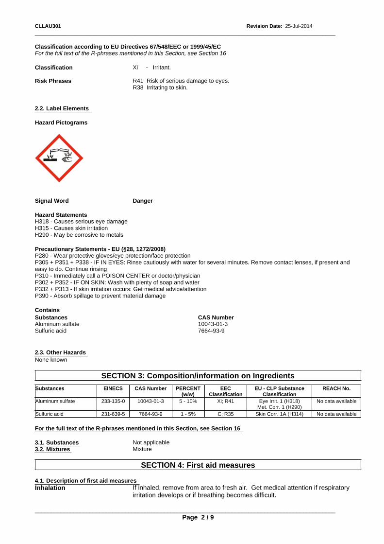
_____________________________________________________________________________________________CLLAU301 Revision Date: 25-Jul-2014
2.3. Other Hazards
Classification according to EU Directives 67/548/EEC or 1999/45/EC
None known
Hazard StatementsH318 - Causes serious eye damageH315 - Causes skin irritationH290 - May be corrosive to metals
SECTION 3: Composition/information on Ingredients
Substances EINECS CAS Number PERCENT(w/w)
EECClassification
EU - CLP SubstanceClassification
REACH No.
Classification
Aluminum sulfate 233-135-0 10043-01-3 5 - 10% Xi; R41 Eye Irrit. 1 (H318)Met. Corr. 1 (H290)
No data available
Precautionary Statements - EU (§28, 1272/2008)P280 - Wear protective gloves/eye protection/face protectionP305 + P351 + P338 - IF IN EYES: Rinse cautiously with water for several minutes. Remove contact lenses, if present andeasy to do. Continue rinsingP310 - Immediately call a POISON CENTER or doctor/physicianP302 + P352 - IF ON SKIN: Wash with plenty of soap and waterP332 + P313 - If skin irritation occurs: Get medical advice/attentionP390 - Absorb spillage to prevent material damage
Xi - Irritant.
Sulfuric acid 231-639-5 7664-93-9 1 - 5% C; R35 Skin Corr. 1A (H314) No data available
2.2. Label Elements
For the full text of the R-phrases mentioned in this Section, see Section 16
Contains
For the full text of the R-phrases mentioned in this Section, see Section 16
3.1. Substances Not applicable
Substances
3.2. Mixtures Mixture
CAS NumberAluminum sulfate
SECTION 4: First aid measures
10043-01-3
Risk Phrases
Sulfuric acid
4.1. Description of first aid measures
7664-93-9
Inhalation If inhaled, remove from area to fresh air. Get medical attention if respiratoryirritation develops or if breathing becomes difficult.
R41 Risk of serious damage to eyes.R38 Irritating to skin.
Hazard Pictograms
Signal Word Danger
_____________________________________________________________________________________________Page 2 / 9
_____________________________________________________________________________________________CLLAU301 Revision Date: 25-Jul-2014
7.1. Precautions for Safe Handling
Extinguishing media which must not be used for safety reasonsNone known.
6.1. Personal precautions, protective equipment and emergency procedures
Avoid contact with eyes, skin, or clothing. Avoid breathing mist.
4.3. Indication of any immediate medical attention and special treatment needed
Eyes
Hygiene MeasuresHandle in accordance with good industrial hygiene and safety practice
Use appropriate protective equipment.
Immediately flush eyes with large amounts of water for at least 15 minutes. Getimmediate medical attention.
See Section 8 for additional information
7.2. Conditions for safe storage, including any incompatibilities
Notes to Physician
5.2. Special hazards arising from the substance or mixture
Store in a cool, dry location. Product has a shelf life of 24 months.
Treat symptomatically
4.2. Most Important symptoms and effects, both acute and delayed
6.2. Environmental precautions
7.3. Specific End Use(s)
Special Exposure HazardsNot applicable.
Ingestion
Exposure Scenario No information available
Prevent from entering sewers, waterways, or low areas.
Other Guidelines No information available
Do not induce vomiting. Slowly dilute with 1-2 glasses of water or milk andseek medical attention. Never give anything by mouth to an unconsciousperson.
May cause severe eye irritation. May cause skin irritation.
SECTION 8: Exposure Controls/Personal Protection
6.3. Methods and material for containment and cleaning up Isolate spill and stop leak where safe. Neutralize with lime slurry, limestone, or soda ash. Contain spill with sand or other inertmaterials. Scoop up and remove.
8.1. Control parameters
SECTION 5: Firefighting Measures
Skin
Exposure Limits
5.3. Advice for firefighters
Substances CAS Number EU UK OEL Netherlands France OEL
Wash with soap and water. Get medical attention if irritation persists.
6.4. Reference to other sections
Aluminum sulfate 10043-01-3 Not applicable 2 mg/m3 2 mg/m3 Not applicable
5.1. Extinguishing media
Special Protective Equipment for Fire-FightersNot applicable.
Sulfuric acid 7664-93-9 Not applicable 0.3 mg/m3 0.05 mg/m3 1 mg/m3
See Section 8 and 13 for additional information.
SECTION 6: Accidental release measures
_____________________________________________________________________________________________
Suitable Extinguishing MediaAll standard fire fighting media
SECTION 7: Handling and Storage
Page 3 / 9
_____________________________________________________________________________________________Revision Date: 25-Jul-2014CLLAU301
Austria Ireland Switzerland Norway
Derived No Effect Level (DNEL) No information available.Worker
Aluminum sulfate 10043-01-3 Not applicable Not applicable
General Population
Not applicable STEL: 4 mg/m3
TWA: 2 mg/m3
Aluminum sulfate 10043-01-3
Predicted No Effect Concentration (PNEC) No information available.
Sulfuric acid 7664-93-9 Not applicable Not applicable
8.2. Exposure controls
Not applicable STEL: 0.3 mg/m3
TWA: 0.1 mg/m3
Engineering Controls Use in a well ventilated area.
Not applicable VLA-ED: 2 mg/m3
Personal protective equipmentIf engineering controls and work practices cannot prevent excessive exposures, the selection and proper use of personalprotective equipment should be determined by an industrial hygienist or other qualified professional based on the specificapplication of this product.
TWA: 2 mg/m3 TWA: 1 mg/m3
Substances CAS Number
Respiratory Protection If engineering controls and work practices cannot keep exposure below occupationalexposure limits or if exposure is unknown, wear a NIOSH certified, European StandardEN 149, AS/NZS 1715:2009, or equivalent respirator when using this product. Selectionof and instruction on using all personal protective equipment, including respirators,should be performed by an Industrial Hygienist or other qualified professional.Dust/mist respirator. (N95, P2/P3)
Italy Poland
Hand Protection Chemical-resistant protective gloves (EN 374) Suitable materials for longer, directcontact (recommended: protection index 6, corresponding to > 480 minutes permeationtime as per EN 374): Butyl rubber gloves. (>= 0.7 mm thickness)This information is based on literature references and on information provided by glovemanufacturers, or is derived by analogy with similar substances. Please note that inpractice the working life of chemical-resistant protective gloves may be considerablyshorter than the permeation time determined in accordance with EN 374 as a result ofthe many influencing factors (e.g. temperature). If signs of wear and tear are noticedthen the gloves should be replaced. Manufacturer's directions for use should beobserved because of great diversity of types.
Hungary Czech Republic
Skin Protection Normal work coveralls.
Substances CAS Number
Eye Protection Wear safety glasses or goggles to protect against exposure.
Aluminum sulfate 10043-01-3
Other Precautions None known.
Not applicable Not applicable Not applicable Not applicable
Environmental Exposure Controls No information available
Sulfuric acid 7664-93-9
Sulfuric acid 7664-93-9 Not applicable NDSCh: 3 mg/m3
NDS: 1 mg/m3
SECTION 9: Physical and Chemical Properties
TWA: 1 mg/m3
STEL: 1 mg/m3
TWA: 1 mg/m3
MAK: 0.1 mg/m3 3 mg/m3 VLA-ECVLA-ED: 1 mg/m3
9.1. Information on basic physical and chemical properties
TWA: 0.2 mg/m3 STEL: 1 mg/m3
TWA: 0.2 mg/m3
Substances CAS Number Denmark
Germany MAK/TRK Spain
Aluminum sulfate 10043-01-3 TWA: 1 mg/m3
Sulfuric acid 7664-93-9 TWA: 1 mg/m3
Portugal Finland
Substances CAS Number
No information availableOdor: OdorlessPhysical State:
_____________________________________________________________________________________________
Liquid Color:
Page 4 / 9
WhiteOdor Threshold:
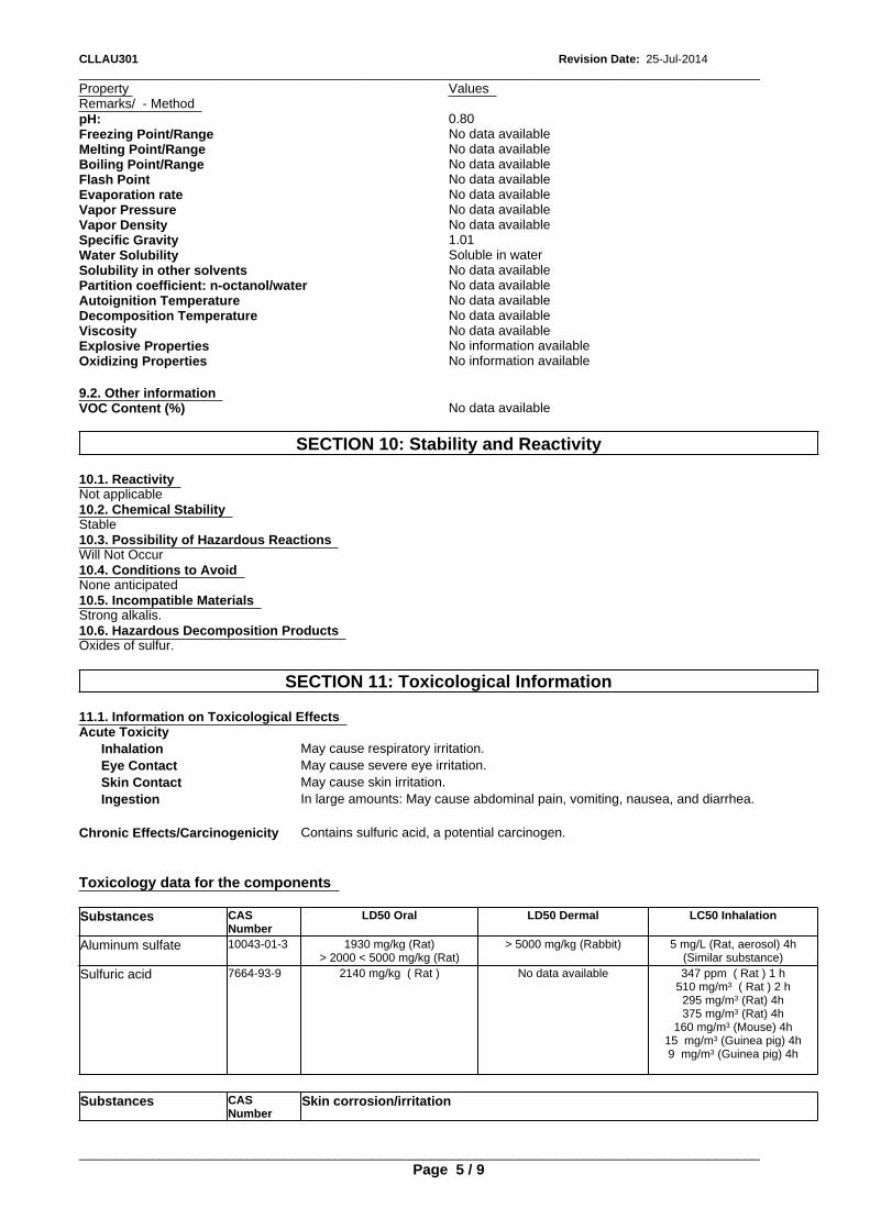
_____________________________________________________________________________________________CLLAU301 Revision Date: 25-Jul-2014
No data available
Explosive Properties
Strong alkalis.
No information available
0.80
10.6. Hazardous Decomposition Products
Vapor Density
Oxidizing Properties
Oxides of sulfur.
No information available
No data available
Remarks/ - Method
SECTION 11: Toxicological Information
Boiling Point/Range
Specific Gravity
9.2. Other information
11.1. Information on Toxicological Effects
1.01
No data available
Acute Toxicity
VOC Content (%) No data available
Inhalation May cause respiratory irritation.
Property
Water Solubility
Eye Contact May cause severe eye irritation.
Soluble in water
Skin Contact May cause skin irritation.
Freezing Point/Range
SECTION 10: Stability and Reactivity
Ingestion In large amounts: May cause abdominal pain, vomiting, nausea, and diarrhea.
Flash Point
Solubility in other solvents
Chronic Effects/Carcinogenicity Contains sulfuric acid, a potential carcinogen.
No data available
No data available
10.1. Reactivity
No data available
Partition coefficient: n-octanol/water
Not applicable
Toxicology data for the components
No data available
Values
10.2. Chemical Stability
Evaporation rate
Substances CASNumber
LD50 Oral LD50 Dermal LC50 Inhalation
Autoignition Temperature
Stable
Aluminum sulfate 10043-01-3 1930 mg/kg (Rat)> 2000 < 5000 mg/kg (Rat)
> 5000 mg/kg (Rabbit) 5 mg/L (Rat, aerosol) 4h(Similar substance)
No data available
No data available
Sulfuric acid 7664-93-9 2140 mg/kg ( Rat ) No data available 347 ppm ( Rat ) 1 h510 mg/m3 ( Rat ) 2 h295 mg/m3 (Rat) 4h375 mg/m3 (Rat) 4h
160 mg/m3 (Mouse) 4h15 mg/m3 (Guinea pig) 4h9 mg/m3 (Guinea pig) 4h
10.3. Possibility of Hazardous Reactions
pH:
Decomposition Temperature
Will Not Occur
Substances CASNumber
Skin corrosion/irritation
No data available
Melting Point/Range
10.4. Conditions to Avoid
Vapor Pressure
Viscosity
_____________________________________________________________________________________________
None anticipated
No data available
Page 5 / 9
No data available
10.5. Incompatible Materials
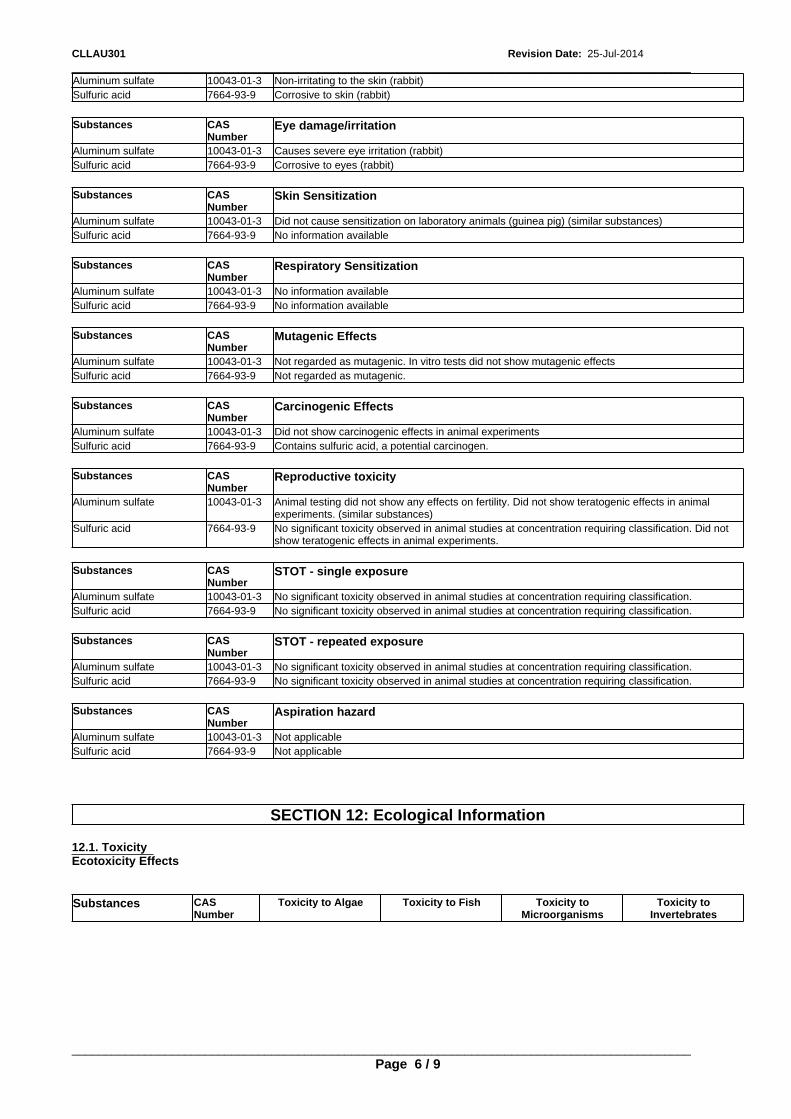
_____________________________________________________________________________________________Revision Date: 25-Jul-2014CLLAU301
Eye damage/irritation
Sulfuric acid 7664-93-9 Contains sulfuric acid, a potential carcinogen.
7664-93-9
Sulfuric acid 7664-93-9 No information available
Substances CASNumber
Reproductive toxicity
Corrosive to skin (rabbit)
Aluminum sulfate
Aluminum sulfate 10043-01-3 Animal testing did not show any effects on fertility. Did not show teratogenic effects in animalexperiments. (similar substances)
Sulfuric acid 7664-93-9 No significant toxicity observed in animal studies at concentration requiring classification. Did notshow teratogenic effects in animal experiments.
10043-01-3 Causes severe eye irritation (rabbit)
Substances CASNumber
Substances CASNumber
STOT - single exposure
Respiratory Sensitization
Non-irritating to the skin (rabbit)
Aluminum sulfate 10043-01-3 No significant toxicity observed in animal studies at concentration requiring classification.
Aluminum sulfate
Aluminum sulfate
Sulfuric acid 7664-93-9 No significant toxicity observed in animal studies at concentration requiring classification.
10043-01-3 No information available
Sulfuric acid 7664-93-9
Substances CASNumber
STOT - repeated exposure
Sulfuric acid 7664-93-9
Aluminum sulfate 10043-01-3 No significant toxicity observed in animal studies at concentration requiring classification.
No information available
Corrosive to eyes (rabbit)
Sulfuric acid 7664-93-9 No significant toxicity observed in animal studies at concentration requiring classification.
Substances CASNumber
Aspiration hazard
Substances
Aluminum sulfate 10043-01-3 Not applicable
CASNumber
Mutagenic Effects
Sulfuric acid 7664-93-9 Not applicable
10043-01-3
Aluminum sulfate 10043-01-3 Not regarded as mutagenic. In vitro tests did not show mutagenic effects
Sulfuric acid
Substances
Sulfuric acid
SECTION 12: Ecological Information
7664-93-9 Not regarded as mutagenic.
CASNumber
Skin Sensitization
12.1. Toxicity Ecotoxicity Effects
Substances CASNumber
Substances CASNumber
Toxicity to Algae Toxicity to Fish Toxicity toMicroorganisms
Toxicity toInvertebrates
Substances CASNumber
Carcinogenic Effects
Aluminum sulfate 10043-01-3
_____________________________________________________________________________________________
Aluminum sulfate 10043-01-3
Page 6 / 9
Did not show carcinogenic effects in animal experiments
Did not cause sensitization on laboratory animals (guinea pig) (similar substances)
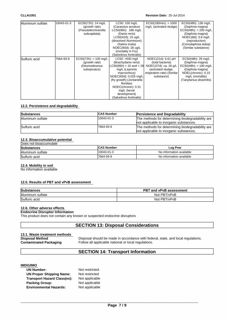
_____________________________________________________________________________________________CLLAU301 Revision Date: 25-Jul-2014
Not PBT/vPvB
12.3. Bioaccumulative potential
Sulfuric acid Not PBT/vPvB
EC50(180min): > 1000mg/L (activated sludge)
EC50(48h): 136 mg/L(Daphnia magna)
EC50(48h): > 200 mg/L(Daphnia magna)
NOEC(8d): 3.8 mg/L(reproduction)
(Ceriodaphnia dubia)(Similar substance)
Does not bioaccumulate
12.2. Persistence and degradability
12.6. Other adverse effects
Aluminum sulfate
Substances
Endocrine Disruptor InformationThis product does not contain any known or suspected endocrine disruptors
CAS Number Log Pow
10043-01-3
SECTION 13: Disposal Considerations
Aluminum sulfate 10043-01-3 No information available
Sulfuric acid
13.1. Waste treatment methods
7664-93-9
Sulfuric acid
Disposal Method Disposal should be made in accordance with federal, state, and local regulations.
7664-93-9 No information available
Contaminated Packaging Follow all applicable national or local regulations.
Substances CAS Number
SECTION 14: Transport Information
Persistence and Degradability
EC50(72h): > 100 mg/L(growth rate)
(Desmodesmussubspicatus)
12.4. Mobility in soil
LC50: >500 mg/l(Brachydanio rerio)
LC50(96h) > 16 and < 28mg/L (Lepomismacrochirus)
NOEC(65d): 0.025 mg/L(fry growth) (Jordanella
floridae)NOEC(chronic): 0.31
mg/L (larvaldevelopment)
(Salvelinus fontinalis)
Aluminum sulfate
No information available
IMDG/IMO
10043-01-3 The methods for determining biodegradability arenot applicable to inorganic substances.
UN Number: Not restricted.UN Proper Shipping Name: Not restricted
NOEC(21d): 6.61 pH(total bacteria)
NOEC(37d): ca. 26 g/L(activated sludge,
respiration rate) (Similarsubstance)
EC50(48h): 29 mg/L(Daphnia magna)
EC50(48h): > 100 mg/L(Daphnia magna)
NOEL(chronic): 0.15mg/L (mortality)
(Tanytarsus dissimilis)
Transport Hazard Class(es): Not applicablePacking Group: Not applicable
Sulfuric acid 7664-93-9
Environmental Hazards: Not applicable
12.5. Results of PBT and vPvB assessment
The methods for determining biodegradability arenot applicable to inorganic substances.
EC50(72h): 14 mg/L(growth rate)
(Pseudokirchnerellasubcapitata)
LC50: 100 mg/L(Carassius auratus)
LC50(96h): 186 mg/L(Danio rerio)
LC50(42d): 15 ug/L(dissolved Aluminium)
(Salmo trutta)NOEC(60d): 26 ug/L
(mortality in Fry)(Salvelinus fontinalis)
Substances
_____________________________________________________________________________________________
PBT and vPvB assessment
Page 7 / 9
Aluminum sulfate
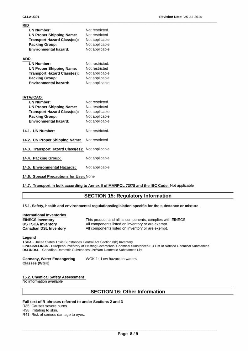
_____________________________________________________________________________________________CLLAU301 Revision Date: 25-Jul-2014
14.4. Packing Group: Not applicable
Environmental hazard: Not applicable
14.5. Environmental Hazards: Not applicable
Environmental hazard:
14.6. Special Precautions for User: None
Not applicable
UN Proper Shipping Name:
14.7. Transport in bulk according to Annex II of MARPOL 73/78 and the IBC Code: Not applicable
Not restricted
IATA/ICAO
SECTION 15: Regulatory Information
UN Number:
15.1. Safety, health and environmental regulations/legislation specific for the substance or mixture
Not restricted.
UN Number:
ADR
International Inventories
UN Proper Shipping Name: Not restricted
EINECS Inventory This product, and all its components, complies with EINECSUS TSCA Inventory All components listed on inventory or are exempt.
Transport Hazard Class(es):
Canadian DSL Inventory All components listed on inventory or are exempt.
Not applicable
Transport Hazard Class(es):
Legend
Packing Group: Not applicable
TSCA - United States Toxic Substances Control Act Section 8(b) Inventory
UN Number: Not restricted.
EINECS/ELINCS - European Inventory of Existing Commercial Chemical Substances/EU List of Notified Chemical Substances
Environmental hazard:
DSL/NDSL - Canadian Domestic Substances List/Non-Domestic Substances List
Not applicable
Not applicable
Not restricted.
Germany, Water EndangeringClasses (WGK)
WGK 1: Low hazard to waters.
UN Proper Shipping Name:
14.1. UN Number: Not restricted.
Not restricted
15.2. Chemical Safety Assessment
RID
No information available
14.2. UN Proper Shipping Name:
SECTION 16: Other Information
Not restricted
Transport Hazard Class(es): Not applicable
Full text of R-phrases referred to under Sections 2 and 3
Packing Group:
R35 Causes severe burns.R38 Irritating to skin.R41 Risk of serious damage to eyes.
Not applicable
14.3. Transport Hazard Class(es): Not applicable
Packing Group:
_____________________________________________________________________________________________Page 8 / 9
Not applicable
_____________________________________________________________________________________________Revision Date: 25-Jul-2014CLLAU301
Revision Note
Disclaimer StatementThis information is furnished without warranty, expressed or implied, as to accuracy or completeness. The information isobtained from various sources including the manufacturer and other third party sources. The information may not be validunder all conditions nor if this material is used in combination with other materials or in any process. Final determination ofsuitability of any material is the sole responsibility of the user.
Update to Format SECTION: 8
End of Safety Data Sheet
_____________________________________________________________________________________________
Revision Date:
This safety data sheet complies with the requirements of Regulation (EC) No. 453/2010
Page 9 / 9
25-Jul-2014
Key literature references and sources for datawww.ChemADVISOR.com/

SAFETY DATA SHEETaccording to Regulation (EC) No. 453/2010
CLBEAU196Revision Date: 25-Jul-2014 Revision Number: 6
ORFILA (FR): + 01 45 42 59 59
CLBEAU196
Germany Poison Center Berlin (DE): +49 030 30686 790
1.3. Details of the supplier of the safety data sheet
Italy Poison Center, Milan (IT): +39 02 6610 1029
Recommended Use Breaker
Netherlands National Poisons Information Center (NL): +31 30 274 88 88 (NB: this service is onlyavailable to health professionals)
Halliburton Energy ServicesHalliburton House, Howemoss PlaceKirkhill Industrial EstateDyceAberdeen, AB21 0GNUnited Kingdom
Emergency Phone Number: +44 1224 795277 or +1 281 575 5000
www.halliburton.com
Norway Poisons Information (NO):+ 47 22 591300
SECTION 1: Identification of the substance/mixture and of the company/undertaking
1.1. Product Identifier
Poland Poison Control and Information Centre, Warsaw (PL): +48 22 619 66 54; +48 22 619 0897
For further information, please contact
Spain Poison Information Service (ES): +34 91 562 04 20
Sector of use
E-Mail address:
United Kingdom NHS Direct (UK): +44 0845 46 47
SU2 - Mining, (including offshore industries)
1.4. Emergency telephone number
SECTION 2: Hazards Identification
+44 1224 795277 or +1 281 575 5000
Product category
2.1. Classification of the substance or mixture
PC20 - Products such as pH-regulators, flocculants, precipitants, neutralization agents,other unspecific
REGULATION (EC) No 1272/2008Respiratory Sensitization Category 1 - (H334)
Emergency telephone - §45 - (EC)1272/2008
Process categories
Classification according to EU Directives 67/548/EEC or 1999/45/EC
Europe 112
PROC4 - Use in batch and other process (synthesis) where opportunity for exposurearises
1.2. Relevant identified uses of the substance or mixture and uses advised against
Denmark
_____________________________________________________________________________________________
Poison Control Hotline (DK): +45 82 12 12 12
Product Name
Page 1 / 8
France
_____________________________________________________________________________________________Revision Date: 25-Jul-2014CLBEAU196
EU - CLP SubstanceClassification
REACH No.
Precautionary Statements - EU (§28, 1272/2008)P261 - Avoid breathing dust/fume/gas/mist/vapors/sprayP285 - In case of inadequate ventilation wear respiratory protectionP304 + P341 - IF INHALED: If breathing is difficult, remove to fresh air and keep at rest in a position comfortable for breathingP342 + P311 - If experiencing respiratory symptoms: Call a POISON CENTER or doctor/physician
Hemicellulase enzyme 232-734-4 9012-54-8 1 - 5% Xn; R42 Resp. Sens. 1 (H334) No data available
For the full text of the R-phrases mentioned in this Section, see Section 16
For the full text of the R-phrases mentioned in this Section, see Section 16
Contains
3.1. Substances Not applicable
Hazard Pictograms
3.2. Mixtures Mixture
Substances CAS Number
SECTION 4: First aid measures
Hemicellulase enzyme 9012-54-8
Classification
4.1. Description of first aid measures Inhalation If inhaled, remove from area to fresh air. Get medical attention if respiratory
irritation develops or if breathing becomes difficult.
Signal Word Danger
Eyes In case of contact, immediately flush eyes with plenty of water for at least 15minutes and get medical attention if irritation persists.
Skin Wash with soap and water. Get medical attention if irritation persists.Ingestion Under normal conditions, first aid procedures are not required.
2.3. Other Hazards
4.2. Most Important symptoms and effects, both acute and delayed
Dust can form an explosive mixture in air
Risk Phrases
May cause mild eye, skin, and respiratory irritation. May cause allergic respiratory reaction.
2.2. Label Elements
Hazard StatementsH334 - May cause allergy or asthma symptoms or breathing difficulties if inhaled
R42 May cause sensitization by inhalation.
4.3. Indication of any immediate medical attention and special treatment needed
SECTION 3: Composition/information on Ingredients
Xn - Harmful.
Notes to Physician Treat symptomatically
Substances EINECS CAS Number PERCENT(w/w)
_____________________________________________________________________________________________
EECClassification
Page 2 / 8
_____________________________________________________________________________________________CLBEAU196 Revision Date: 25-Jul-2014
SECTION 8: Exposure Controls/Personal Protection
Special Exposure HazardsOrganic dust in the presence of an ignition source can be explosive in high concentrations. Good housekeeping practices arerequired to minimize this potential.
SECTION 7: Handling and Storage
8.1. Control parameters
Special Protective Equipment for Fire-FightersFull protective clothing and approved self-contained breathing apparatus required for fire fighting personnel.
Suitable Extinguishing MediaAll standard fire fighting media
Exposure LimitsSubstances CAS Number EU UK OEL Netherlands France OEL
6.2. Environmental precautions
Hemicellulase enzyme 9012-54-8 Not applicable Not applicable Not applicable Not applicable
7.1. Precautions for Safe Handling
SECTION 6: Accidental release measures
Prevent from entering sewers, waterways, or low areas.
Avoid creating or inhaling dust. Slippery when wet.
Substances CAS Number Germany MAK/TRK Spain Portugal Finland
5.1. Extinguishing media
Hemicellulase enzyme 9012-54-8 Not applicable Not applicable Not applicable Not applicable
Hygiene MeasuresHandle in accordance with good industrial hygiene and safety practice
Substances CAS Number Austria Ireland Switzerland Norway
6.3. Methods and material for containment and cleaning up
Hemicellulase enzyme 9012-54-8 Not applicable Not applicable Not applicable Not applicable
7.2. Conditions for safe storage, including any incompatibilities Store away from oxidizers. Store in a cool, dry location. Product has a shelf life of 18 months.
Substances CAS Number Italy Poland Hungary Czech Republic
Scoop up and remove.
6.1. Personal precautions, protective equipment and emergency procedures
Hemicellulase enzyme 9012-54-8 Not applicable Not applicable Not applicable Not applicable
7.3. Specific End Use(s)
Substances CAS Number Denmark
5.2. Special hazards arising from the substance or mixture
Use appropriate protective equipment. Avoid creating and breathing dust.
Hemicellulase enzyme 9012-54-8 Not applicable
Exposure Scenario No information available
6.4. Reference to other sections
Extinguishing media which must not be used for safety reasonsNone known.
Other Guidelines No information available
5.3. Advice for firefighters
_____________________________________________________________________________________________
See Section 8 and 13 for additional information.
Page 3 / 8
See Section 8 for additional information
SECTION 5: Firefighting Measures
_____________________________________________________________________________________________CLBEAU196 Revision Date: 25-Jul-2014
pH: 3.8-8 (1%)
Eye Protection Wear safety glasses or goggles to protect against exposure.
Freezing Point/Range No data availableMelting Point/Range No data available
Other Precautions
Boiling Point/Range No data available
None known.
8.2. Exposure controls
Flash Point No data available
Derived No Effect Level (DNEL)
Evaporation rate No data available
No information available.
Vapor Pressure No data available
Engineering Controls
Environmental Exposure Controls
Vapor Density No data available
No information available
Use in a well ventilated area.
Specific Gravity No data available
General Population
Water Solubility dispersibleSolubility in other solvents No data available
Personal protective equipment
Partition coefficient: n-octanol/water No data availableAutoignition Temperature No data available
SECTION 9: Physical and Chemical Properties
Decomposition Temperature No data availableViscosity No data available
If engineering controls and work practices cannot prevent excessive exposures, the selection and proper use of personalprotective equipment should be determined by an industrial hygienist or other qualified professional based on the specificapplication of this product.
Explosive Properties No information available
9.1. Information on basic physical and chemical properties
Oxidizing Properties No information available
Worker
9.2. Other information VOC Content (%) No data available
Respiratory Protection If engineering controls and work practices cannot keep exposure below occupationalexposure limits or if exposure is unknown, wear a NIOSH certified, European StandardEN 149, AS/NZS 1715:2009, or equivalent respirator when using this product. Selectionof and instruction on using all personal protective equipment, including respirators,should be performed by an Industrial Hygienist or other qualified professional.Dust/mist respirator. (N95, P2/P3)
Predicted No Effect Concentration (PNEC)
SECTION 10: Stability and Reactivity
No information available.
Hand Protection
10.1. Reactivity
Normal work gloves.
Not applicable10.2. Chemical Stability
Skin Protection
Property Values
Normal work coveralls.
Remarks/ - Method
Odor: Characteristic
Physical State: Powder
_____________________________________________________________________________________________
Color: White to Tan
Page 4 / 8
Odor Threshold: No information available
_____________________________________________________________________________________________Revision Date: 25-Jul-2014CLBEAU196
9012-54-8 Non-irritating to the skin (rabbit)
None known.
10.6. Hazardous Decomposition Products
Substances CASNumber
Eye damage/irritation
Ingestion None known
Hemicellulase enzyme 9012-54-8 Non-irritating to the eye (rabbit)
10.4. Conditions to Avoid
Substances CASNumber
Skin Sensitization
10.5. Incompatible Materials
11.1. Information on Toxicological Effects
Hemicellulase enzyme 9012-54-8 No information available
Chronic Effects/Carcinogenicity No data available to indicate product or components present at greater than 1% arechronic health hazards.
Carbon monoxide and carbon dioxide.
Will Not Occur
Substances CASNumber
Respiratory Sensitization
Hemicellulase enzyme 9012-54-8 May cause sensitization by inhalation
Acute Toxicity
Substances CASNumber
Mutagenic Effects
Stable
Hemicellulase enzyme 9012-54-8 In vitro tests did not show mutagenic effects
Toxicology data for the components
Inhalation
Substances CASNumber
Carcinogenic Effects
May cause allergic respiratory reaction. May cause mild respiratory irritation.
Hemicellulase enzyme 9012-54-8 No information available.
Strong oxidizers.
Substances CASNumber
LD50 Oral
Substances CASNumber
Reproductive toxicity
LD50 Dermal LC50 Inhalation
Hemicellulase enzyme 9012-54-8 No information available
None anticipated
Hemicellulase enzyme 9012-54-8
Substances CASNumber
STOT - single exposure
> 2000 mg/kg (Rat) (Similarsubstance)
> 10000 mg/kg (Rat)> 8000 mg/kg (Mouse)
> 2880 mg/kg (Rat)
No data available
Hemicellulase enzyme 9012-54-8 No significant toxicity observed in animal studies at concentration requiring classification.
> 3.5 mg/L (Rat) 4h > 4.86 mg/L (Rat) 4h
Eye Contact May cause mild eye irritation.
Substances CASNumber
STOT - repeated exposure
SECTION 11: Toxicological Information
10.3. Possibility of Hazardous Reactions
Substances CASNumber
_____________________________________________________________________________________________
Skin corrosion/irritation
Page 5 / 8
Skin Contact
Hemicellulase enzyme
_____________________________________________________________________________________________CLBEAU196 Revision Date: 25-Jul-2014
LC50(96h): >/= 100mg/L Total Organic
Solids (Oncorhynchusmykiss)
LC50(96h): > 52.1 mg/L(Oncorhynchus mykiss)
No information available
12.5. Results of PBT and vPvB assessment
EC50(48h): > 39.5 mg/L(Daphnia magna)
EC50(48h): >/= 100mg/L Total Organic
Solids (Daphnia magna)EC50(48h): > 52.1 mg/L
(mobility) (Daphniamagna)
No information available.
CASNumber
Aspiration hazard
12.6. Other adverse effects
12.2. Persistence and degradability
Endocrine Disruptor InformationThis product does not contain any known or suspected endocrine disruptors
9012-54-8
Readily biodegradable
SECTION 12: Ecological Information
SECTION 13: Disposal Considerations
Hemicellulase enzyme
Substances CAS Number Persistence and Degradability
13.1. Waste treatment methods
9012-54-8
Disposal Method Bury in a licensed landfill according to federal, state, and local regulations.
Hemicellulase enzyme 9012-54-8
Contaminated Packaging Follow all applicable national or local regulations.
Readily biodegradable (129% @ 28d)
Not applicable
SECTION 14: Transport Information
12.1. Toxicity
12.3. Bioaccumulative potential
No significant toxicity observed in animal studies at concentration requiring classification.
IMDG/IMO
Does not bioaccumulate
Ecotoxicity Effects
UN Number: Not restricted.
Substances
UN Proper Shipping Name: Not restricted
CAS Number Log Pow
Transport Hazard Class(es): Not applicable
Hemicellulase enzyme
Substances
Packing Group: Not applicable
Hemicellulase enzyme 9012-54-8
Environmental Hazards: Not applicable
-2.95 (Similar substance)
CASNumber
Toxicity to Algae
RID
Toxicity to Fish
UN Number: Not restricted.
Toxicity toMicroorganisms
12.4. Mobility in soil
UN Proper Shipping Name: Not restricted
Toxicity toInvertebrates
Substances
No information available
Hemicellulaseenzyme
_____________________________________________________________________________________________Page 6 / 8
9012-54-8 EC50(72h) >/= 100 mg/LTotal Organic Solids(Pseudokirchnerella
subcapitata)EC50(72h): > 52.1 mg/L
(Biomass)(Pseudokirchneriella
subcapitata)
_____________________________________________________________________________________________Revision Date: 25-Jul-2014CLBEAU196
14.6. Special Precautions for User: None
UN Number: Not restricted.
UN Number:
14.7. Transport in bulk according to Annex II of MARPOL 73/78 and the IBC Code: Not applicable
Not restricted.
Environmental hazard:
SECTION 15: Regulatory Information
UN Proper Shipping Name: Not restricted
UN Proper Shipping Name:
15.1. Safety, health and environmental regulations/legislation specific for the substance or mixture
Transport Hazard Class(es): Not applicable
Not restricted
International Inventories
Not applicable
EINECS Inventory This product, and all its components, complies with EINECS
Packing Group: Not applicable
US TSCA Inventory All components listed on inventory or are exempt.
Transport Hazard Class(es):
Canadian DSL Inventory All components listed on inventory or are exempt.
Environmental hazard: Not applicable
Transport Hazard Class(es):
Legend
Not applicable
TSCA - United States Toxic Substances Control Act Section 8(b) InventoryEINECS/ELINCS - European Inventory of Existing Commercial Chemical Substances/EU List of Notified Chemical Substances
14.1. UN Number:
DSL/NDSL - Canadian Domestic Substances List/Non-Domestic Substances List
Not restricted.
Packing Group:
Germany, Water EndangeringClasses (WGK)
WGK 1: Low hazard to waters.
Not applicable
14.2. UN Proper Shipping Name: Not restricted
Packing Group:
15.2. Chemical Safety Assessment No information available
Environmental hazard: Not applicable
14.3. Transport Hazard Class(es):
SECTION 16: Other Information
Not applicable
Not applicable
ADR
Full text of R-phrases referred to under Sections 2 and 3R42 May cause sensitization by inhalation.
14.4. Packing Group: Not applicable
Not applicable
Key literature references and sources for datawww.ChemADVISOR.com/
14.5. Environmental Hazards: Not applicable
_____________________________________________________________________________________________Page 7 / 8
IATA/ICAO
_____________________________________________________________________________________________CLBEAU196 Revision Date: 25-Jul-2014
25-Jul-2014
This safety data sheet complies with the requirements of Regulation (EC) No. 453/2010
End of Safety Data Sheet
Update to Format SECTION: 8Revision Note
_____________________________________________________________________________________________
Disclaimer StatementThis information is furnished without warranty, expressed or implied, as to accuracy or completeness. The information isobtained from various sources including the manufacturer and other third party sources. The information may not be validunder all conditions nor if this material is used in combination with other materials or in any process. Final determination ofsuitability of any material is the sole responsibility of the user.
Page 8 / 8
Revision Date:

SAFETY DATA SHEETaccording to Regulation (EC) No. 453/2010
CLLAU302Revision Date: 05-Aug-2014 Revision Number: 2
ORFILA (FR): + 01 45 42 59 59
CLLAU302
Germany Poison Center Berlin (DE): +49 030 30686 790
1.3. Details of the supplier of the safety data sheet
Italy Poison Center, Milan (IT): +39 02 6610 1029
Recommended Use Crosslinker
Netherlands National Poisons Information Center (NL): +31 30 274 88 88 (NB: this service is onlyavailable to health professionals)
Halliburton Energy ServicesHalliburton House, Howemoss PlaceKirkhill Industrial EstateDyceAberdeen, AB21 0GNUnited Kingdom
Emergency Phone Number: +44 1224 795277 or +1 281 575 5000
www.halliburton.com
Norway Poisons Information (NO):+ 47 22 591300
SECTION 1: Identification of the substance/mixture and of the company/undertaking
1.1. Product Identifier
Poland Poison Control and Information Centre, Warsaw (PL): +48 22 619 66 54; +48 22 619 0897
For further information, please contact
Spain Poison Information Service (ES): +34 91 562 04 20
Sector of use
E-Mail address:
United Kingdom NHS Direct (UK): +44 0845 46 47
SU2 - Mining, (including offshore industries)
1.4. Emergency telephone number
SECTION 2: Hazards Identification
+44 1224 795277 or +1 281 575 5000
Product category
2.1. Classification of the substance or mixture
PC20 - Products such as pH-regulators, flocculants, precipitants, neutralization agents,other unspecific
REGULATION (EC) No 1272/2008Not classified
Emergency telephone - §45 - (EC)1272/2008
Process categories
Classification according to EU Directives 67/548/EEC or 1999/45/EC
Europe 112
PROC4 - Use in batch and other process (synthesis) where opportunity for exposurearises
1.2. Relevant identified uses of the substance or mixture and uses advised against
Denmark
_____________________________________________________________________________________________
Poison Control Hotline (DK): +45 82 12 12 12
Product Name
Page 1 / 8
France
_____________________________________________________________________________________________Revision Date: 05-Aug-2014CLLAU302
For the full text of the R-phrases mentioned in this Section, see Section 16
For the full text of the R-phrases mentioned in this Section, see Section 16
Contains
3.1. Substances Not applicable3.2. Mixtures Not applicable
Substances CAS Number
SECTION 4: First aid measures
Sulfuric acid 7664-93-9
4.1. Description of first aid measures Inhalation If inhaled, remove from area to fresh air. Get medical attention if respiratory
irritation develops or if breathing becomes difficult.
Signal Word None
Eyes Immediately flush eyes with large amounts of water for at least 15 minutes. Getimmediate medical attention.
Skin Wash with soap and water. Get medical attention if irritation persists.
Classification
Hazard Pictograms
Ingestion Under normal conditions, first aid procedures are not required.
2.3. Other Hazards
4.2. Most Important symptoms and effects, both acute and delayed
None known
No information available
Risk Phrases
Hazard StatementsNot Classified
2.2. Label Elements
4.3. Indication of any immediate medical attention and special treatment needed
SECTION 3: Composition/information on Ingredients
Notes to Physician Treat symptomatically
SECTION 5: Firefighting Measures
Substances EINECS
5.1. Extinguishing media
CAS Number PERCENT(w/w)
Suitable Extinguishing MediaWater fog, carbon dioxide, foam, dry chemical.
EECClassification
EU - CLP SubstanceClassification
Extinguishing media which must not be used for safety reasonsNone known.
REACH No.
None
Precautionary Statements - EU (§28, 1272/2008)None
Sulfuric acid
5.2. Special hazards arising from the substance or mixture
231-639-5 7664-93-9 1 - 5% C; R35 Skin Corr. 1A (H314) No data available
Not Classified
_____________________________________________________________________________________________
Not classified
Page 2 / 8

_____________________________________________________________________________________________CLLAU302 Revision Date: 05-Aug-2014
Sulfuric acid 7664-93-9 Not applicable 0.3 mg/m3 0.05 mg/m3 1 mg/m3
Substances CAS Number Germany MAK/TRK Spain Portugal Finland
7.2. Conditions for safe storage, including any incompatibilities
Sulfuric acid 7664-93-9 MAK: 0.1 mg/m3 3 mg/m3 VLA-ECVLA-ED: 1 mg/m3
TWA: 0.2 mg/m3 STEL: 1 mg/m3
TWA: 0.2 mg/m3
6.4. Reference to other sections
Store away from oxidizers. Store in a dry location.
Substances CAS Number Austria Ireland Switzerland Norway
6.2. Environmental precautions
Sulfuric acid 7664-93-9 Not applicable Not applicable Not applicable STEL: 0.3 mg/m3
TWA: 0.1 mg/m3
See Section 8 and 13 for additional information.
Special Protective Equipment for Fire-FightersFull protective clothing and approved self-contained breathing apparatus required for fire fighting personnel.
7.3. Specific End Use(s)
6.1. Personal precautions, protective equipment and emergency procedures
Substances CAS Number Italy Poland Hungary Czech Republic
Exposure Scenario
Sulfuric acid 7664-93-9 Not applicable NDSCh: 3 mg/m3
NDS: 1 mg/m3
TWA: 1 mg/m3
STEL: 1 mg/m3
TWA: 1 mg/m3
No information available
Prevent from entering sewers, waterways, or low areas.
Special Exposure HazardsDecomposition in fire may produce toxic gases.
Other Guidelines
Substances CAS Number Denmark
No information available
SECTION 7: Handling and Storage
Sulfuric acid 7664-93-9 TWA: 1 mg/m3
SECTION 8: Exposure Controls/Personal Protection
Use appropriate protective equipment.
Derived No Effect Level (DNEL) No information available.
SECTION 6: Accidental release measures
7.1. Precautions for Safe Handling
Worker
8.1. Control parameters
6.3. Methods and material for containment and cleaning up
5.3. Advice for firefighters
Exposure Limits
General Population
Avoid breathing mist.
See Section 8 for additional information
Substances CAS Number EU UK OEL
_____________________________________________________________________________________________
Netherlands France OEL
Page 3 / 8
Contain spill with sand or other inert materials. Scoop up and remove.
Hygiene MeasuresHandle in accordance with good industrial hygiene and safety practice

_____________________________________________________________________________________________Revision Date: 05-Aug-2014CLLAU302
Impervious rubber gloves.
Vapor Density No data availableSpecific Gravity 1.25
8.2. Exposure controls
9.1. Information on basic physical and chemical properties
Water Solubility Soluble in water
Skin Protection
Solubility in other solvents No data available
Normal work coveralls.
Partition coefficient: n-octanol/water No data availableAutoignition Temperature No data availableDecomposition Temperature No data available
Eye Protection Wear safety glasses or goggles to protect against exposure.
Viscosity No data available
If engineering controls and work practices cannot prevent excessive exposures, the selection and proper use of personalprotective equipment should be determined by an industrial hygienist or other qualified professional based on the specificapplication of this product.
Explosive Properties No information availableOxidizing Properties No information available
Other Precautions Eyewash fountains and safety showers must be easily accessible.
Engineering Controls
9.2. Other information VOC Content (%) No data available
Property Values
SECTION 10: Stability and Reactivity
Use in a well ventilated area.
Remarks/ - Method
Predicted No Effect Concentration (PNEC)
10.1. Reactivity
Environmental Exposure Controls
pH:
Not applicable
4.15
No information available
10.2. Chemical Stability
Freezing Point/Range
Stable
No data available
Respiratory Protection
10.3. Possibility of Hazardous Reactions
Melting Point/Range
Will Not Occur
No data available
10.4. Conditions to Avoid
If engineering controls and work practices cannot keep exposure below occupationalexposure limits or if exposure is unknown, wear a NIOSH certified, European StandardEN 149, AS/NZS 1715:2009, or equivalent respirator when using this product. Selectionof and instruction on using all personal protective equipment, including respirators,should be performed by an Industrial Hygienist or other qualified professional.Not normally needed. But if significant exposures are possible then the followingrespirator is recommended:Dust/mist respirator. (N95, P2/P3)
Boiling Point/Range
None anticipated
No data available
No information available.
10.5. Incompatible Materials
Flash Point
Strong oxidizers.
No data available
Personal protective equipment
Evaporation rate No data available
SECTION 9: Physical and Chemical Properties
Hand Protection
Vapor Pressure No data available
White to yellowOdor Threshold: No information availableOdor:
_____________________________________________________________________________________________
OdorlessPhysical State:
Page 4 / 8
Liquid Color:
_____________________________________________________________________________________________CLLAU302 Revision Date: 05-Aug-2014
Chronic Effects/Carcinogenicity
Sulfuric acid 7664-93-9 Corrosive to eyes (rabbit)
No data available to indicate product or components present at greater than 1% arechronic health hazards.
Inhalation May cause respiratory irritation.
Substances CASNumber
Skin Sensitization
Carbon monoxide and carbon dioxide.
Sulfuric acid 7664-93-9 No information available
SECTION 11: Toxicological Information
Substances CASNumber
Respiratory Sensitization
Eye Contact
Toxicology data for the components
Sulfuric acid 7664-93-9 No information available
May cause eye irritation
11.1. Information on Toxicological Effects
Substances CASNumber
Mutagenic Effects
Sulfuric acid 7664-93-9 Not regarded as mutagenic.
Substances CASNumber
LD50 Oral LD50 Dermal
Substances CASNumber
Carcinogenic Effects
LC50 Inhalation
Skin Contact
Sulfuric acid 7664-93-9 Contains sulfuric acid, a potential carcinogen.
May cause skin irritation.
Sulfuric acid 7664-93-9 2140 mg/kg ( Rat )
Substances CASNumber
Reproductive toxicity
No data available 347 ppm ( Rat ) 1 h510 mg/m3 ( Rat ) 2 h295 mg/m3 (Rat) 4h375 mg/m3 (Rat) 4h
160 mg/m3 (Mouse) 4h15 mg/m3 (Guinea pig) 4h9 mg/m3 (Guinea pig) 4h
Sulfuric acid 7664-93-9 No significant toxicity observed in animal studies at concentration requiring classification. Did notshow teratogenic effects in animal experiments.
10.6. Hazardous Decomposition Products
Acute Toxicity
Substances CASNumber
STOT - single exposure
Ingestion
Sulfuric acid 7664-93-9 No significant toxicity observed in animal studies at concentration requiring classification.
Substances CASNumber
Skin corrosion/irritation
None known
Substances CASNumber
STOT - repeated exposure
Sulfuric acid
Sulfuric acid 7664-93-9 No significant toxicity observed in animal studies at concentration requiring classification.
7664-93-9 Corrosive to skin (rabbit)
_____________________________________________________________________________________________
Substances
Page 5 / 8
CASNumber
Eye damage/irritation
_____________________________________________________________________________________________CLLAU302 Revision Date: 05-Aug-2014
SECTION 12: Ecological Information
12.5. Results of PBT and vPvB assessment No information available.
12.2. Persistence and degradability
Substances PBT and vPvB assessmentSulfuric acid Not PBT/vPvB
CASNumber
Sulfuric acid
Substances CAS Number
12.6. Other adverse effects
Persistence and Degradability
12.1. Toxicity
Endocrine Disruptor InformationThis product does not contain any known or suspected endocrine disruptors
Sulfuric acid 7664-93-9 The methods for determining biodegradability arenot applicable to inorganic substances.
SECTION 13: Disposal Considerations
Ecotoxicity Effects
13.1. Waste treatment methods
7664-93-9 Not applicable
Disposal Method Bury in a licensed landfill according to federal, state, and local regulations.
12.3. Bioaccumulative potential
Substances
Contaminated Packaging Follow all applicable national or local regulations.
CASNumber
Toxicity to Algae Toxicity to Fish
SECTION 14: Transport Information
Substances CAS Number Log Pow
Toxicity toMicroorganisms
Toxicity toInvertebrates
Sulfuric acid
IMDG/IMO
7664-93-9 No information available
UN Number: Not restricted.
Aspiration hazard
UN Proper Shipping Name: Not restrictedTransport Hazard Class(es): Not applicable
Sulfuric acid 7664-93-9
Packing Group: Not applicable
12.4. Mobility in soil
EC50(72h): > 100 mg/L(growth rate)
(Desmodesmussubspicatus)
LC50: >500 mg/l(Brachydanio rerio)
LC50(96h) > 16 and < 28mg/L (Lepomismacrochirus)
NOEC(65d): 0.025 mg/L(fry growth) (Jordanella
floridae)NOEC(chronic): 0.31
mg/L (larvaldevelopment)
(Salvelinus fontinalis)
No information available
NOEC(21d): 6.61 pH(total bacteria)
NOEC(37d): ca. 26 g/L(activated sludge,
respiration rate) (Similarsubstance)
_____________________________________________________________________________________________
EC50(48h): 29 mg/L(Daphnia magna)
EC50(48h): > 100 mg/L(Daphnia magna)
NOEL(chronic): 0.15mg/L (mortality)
(Tanytarsus dissimilis)
Page 6 / 8
Substances

_____________________________________________________________________________________________CLLAU302 Revision Date: 05-Aug-2014
Transport Hazard Class(es): Not applicable
Transport Hazard Class(es):
14.4. Packing Group: Not applicable
Not applicable
Packing Group: Not applicable
14.5. Environmental Hazards: Not applicable
Environmental Hazards:
Environmental hazard:
14.6. Special Precautions for User: None
Not applicable
Packing Group:
14.7. Transport in bulk according to Annex II of MARPOL 73/78 and the IBC Code: Not applicable
Not applicable
SECTION 15: Regulatory Information
IATA/ICAO
15.1. Safety, health and environmental regulations/legislation specific for the substance or mixture
Environmental hazard: Not applicable
International Inventories
UN Number: Not restricted.
EINECS Inventory This product, and all its components, complies with EINECS
UN Number: Not restricted.
US TSCA Inventory All components listed on inventory or are exempt.
UN Proper Shipping Name:
Canadian DSL Inventory All components listed on inventory or are exempt.
Not restricted
Legend
Transport Hazard Class(es): Not applicable
TSCA - United States Toxic Substances Control Act Section 8(b) Inventory
Not applicable
EINECS/ELINCS - European Inventory of Existing Commercial Chemical Substances/EU List of Notified Chemical Substances
Packing Group:
DSL/NDSL - Canadian Domestic Substances List/Non-Domestic Substances List
Not applicable
ADR
Germany, Water EndangeringClasses (WGK)
WGK 1: Low hazard to waters.
Environmental hazard: Not applicable
UN Proper Shipping Name:
15.2. Chemical Safety Assessment
UN Number:
No information available
14.1. UN Number: Not restricted.
Not restricted.
Not restricted
SECTION 16: Other Information
Full text of R-phrases referred to under Sections 2 and 3
14.2. UN Proper Shipping Name: Not restricted
R34 Causes burns.
UN Proper Shipping Name: Not restricted
RID
_____________________________________________________________________________________________
14.3. Transport Hazard Class(es):
Page 7 / 8
Not applicable
_____________________________________________________________________________________________CLLAU302 Revision Date: 05-Aug-2014
05-Aug-2014
Key literature references and sources for datawww.ChemADVISOR.com/
Disclaimer StatementThis information is furnished without warranty, expressed or implied, as to accuracy or completeness. The information isobtained from various sources including the manufacturer and other third party sources. The information may not be validunder all conditions nor if this material is used in combination with other materials or in any process. Final determination ofsuitability of any material is the sole responsibility of the user.
Revision Note
End of Safety Data Sheet
Not applicable
_____________________________________________________________________________________________
Full text of H-Statements referred to under sections 2 and 3H314 - Causes severe skin burns and eye damage
Page 8 / 8
This safety data sheet complies with the requirements of Regulation (EC) No. 453/2010
Revision Date:

SAFETY DATA SHEETaccording to Regulation (EC) No. 453/2010
CLBXTAU121Revision Date: 25-Jul-2014 Revision Number: 7
ORFILA (FR): + 01 45 42 59 59
CLBXTAU121
Germany Poison Center Berlin (DE): +49 030 30686 790
1.3. Details of the supplier of the safety data sheet
Italy Poison Center, Milan (IT): +39 02 6610 1029
Recommended Use Breaker
Netherlands National Poisons Information Center (NL): +31 30 274 88 88 (NB: this service is onlyavailable to health professionals)
Halliburton Energy ServicesHalliburton House, Howemoss PlaceKirkhill Industrial EstateDyceAberdeen, AB21 0GNUnited Kingdom
Emergency Phone Number: +44 1224 795277 or +1 281 575 5000
www.halliburton.com
Norway Poisons Information (NO):+ 47 22 591300
SECTION 1: Identification of the substance/mixture and of the company/undertaking
1.1. Product Identifier
Poland Poison Control and Information Centre, Warsaw (PL): +48 22 619 66 54; +48 22 619 0897
For further information, please contact
Spain Poison Information Service (ES): +34 91 562 04 20
Sector of use
E-Mail address:
United Kingdom NHS Direct (UK): +44 0845 46 47
SU2 - Mining, (including offshore industries)
1.4. Emergency telephone number
SECTION 2: Hazards Identification
+44 1224 795277 or +1 281 575 5000
Product category
2.1. Classification of the substance or mixture
PC20 - Products such as pH-regulators, flocculants, precipitants, neutralization agents,other unspecific
REGULATION (EC) No 1272/2008Not classified
Emergency telephone - §45 - (EC)1272/2008
Process categories
Classification according to EU Directives 67/548/EEC or 1999/45/EC
Europe 112
PROC4 - Use in batch and other process (synthesis) where opportunity for exposurearises
1.2. Relevant identified uses of the substance or mixture and uses advised against
Denmark
_____________________________________________________________________________________________
Poison Control Hotline (DK): +45 82 12 12 12
Product Name
Page 1 / 7
France
_____________________________________________________________________________________________CLBXTAU121 Revision Date: 25-Jul-2014
No data available
Not Classified
Not classified
For the full text of the R-phrases mentioned in this Section, see Section 16
For the full text of the R-phrases mentioned in this Section, see Section 16
Contains
3.1. Substances Substance3.2. Mixtures Not applicable
Substances CAS Number
SECTION 4: First aid measures
Contains no hazardous substances NA
4.1. Description of first aid measures Inhalation If inhaled, remove from area to fresh air. Get medical attention if respiratory
irritation develops or if breathing becomes difficult.
Signal Word None
Eyes In case of contact, immediately flush eyes with plenty of water for at least 15minutes and get medical attention if irritation persists.
Skin Get medical attention if irritation persists. Wash with soap and water.
Classification
Hazard Pictograms
Ingestion Do not induce vomiting. Slowly dilute with 1-2 glasses of water or milk andseek medical attention. Never give anything by mouth to an unconsciousperson.
2.3. Other Hazards
4.2. Most Important symptoms and effects, both acute and delayed
None known
May cause mild eye, skin, and respiratory irritation.
Risk Phrases
Hazard StatementsNot Classified
2.2. Label Elements
4.3. Indication of any immediate medical attention and special treatment needed
SECTION 3: Composition/information on Ingredients
Notes to Physician Treat symptomatically
SECTION 5: Firefighting Measures
Substances EINECS
5.1. Extinguishing media
CAS Number PERCENT(w/w)
Suitable Extinguishing MediaWater fog, carbon dioxide, foam, dry chemical.
EECClassification
EU - CLP SubstanceClassification
Extinguishing media which must not be used for safety reasonsNone known.
REACH No.
None
Precautionary Statements - EU (§28, 1272/2008)Not Classified
Contains no hazardoussubstances
Notapplicable
NA 60 - 100%
_____________________________________________________________________________________________
Not applicable Not applicable
Page 2 / 7
_____________________________________________________________________________________________Revision Date: 25-Jul-2014CLBXTAU121
Substances CAS Number EU UK OEL Netherlands France OEL
Wash hands after use. Avoid contact with eyes, skin, or clothing. Avoid breathing mist. Avoid breathing vapors.
6.3. Methods and material for containment and cleaning up
Contains no hazardoussubstances
NA Not applicable Not applicable Not applicable Not applicable
Use appropriate protective equipment. Slippery when wet.
Hygiene MeasuresHandle in accordance with good industrial hygiene and safety practice
Isolate spill and stop leak where safe. Contain spill with sand or other inert materials. Scoop up and remove.
Substances CAS Number Germany MAK/TRK Spain Portugal FinlandContains no hazardoussubstances
NA Not applicable Not applicable Not applicable Not applicable
See Section 8 for additional information
7.2. Conditions for safe storage, including any incompatibilities
SECTION 6: Accidental release measures
Substances CAS Number Austria Ireland Switzerland Norway
Keep from freezing. Store away from oxidizers. Keep container closed when not in use. Store in a well ventilated area. Producthas a shelf life of 24 months.
5.2. Special hazards arising from the substance or mixture
Contains no hazardoussubstances
NA Not applicable Not applicable Not applicable Not applicable
6.4. Reference to other sections
Substances CAS Number Italy Poland Hungary Czech Republic
7.3. Specific End Use(s)
See Section 8 and 13 for additional information.
Contains no hazardoussubstances
NA Not applicable Not applicable Not applicable Not applicable
Exposure Scenario No information available
6.2. Environmental precautions
Substances CAS Number Denmark
Other Guidelines
Contains no hazardous substances NA Not applicable
No information available
5.3. Advice for firefighters
SECTION 7: Handling and Storage
Prevent from entering sewers, waterways, or low areas.
SECTION 8: Exposure Controls/Personal Protection
Special Exposure HazardsNot applicable.
Derived No Effect Level (DNEL) No information available.Worker
6.1. Personal precautions, protective equipment and emergency procedures
8.1. Control parameters
7.1. Precautions for Safe Handling
_____________________________________________________________________________________________
Exposure Limits
Page 3 / 7
Special Protective Equipment for Fire-FightersFull protective clothing and approved self-contained breathing apparatus required for fire fighting personnel.
_____________________________________________________________________________________________Revision Date: 25-Jul-2014CLBXTAU121
Evaporation rate No data availableVapor Pressure < 1 mmHgVapor Density 9.54Specific Gravity 1.14
SECTION 9: Physical and Chemical Properties
Water Solubility Soluble in water
Respiratory Protection
Solubility in other solvents No data available
If engineering controls and work practices cannot keep exposure below occupationalexposure limits or if exposure is unknown, wear a NIOSH certified, European StandardEN 149, AS/NZS 1715:2009, or equivalent respirator when using this product. Selectionof and instruction on using all personal protective equipment, including respirators,should be performed by an Industrial Hygienist or other qualified professional.Dust/mist respirator. (N95, P2/P3)
Partition coefficient: n-octanol/water 0.33
8.2. Exposure controls
9.1. Information on basic physical and chemical properties
Autoignition Temperature No data available
General Population
Decomposition Temperature No data available
Hand Protection Normal work gloves.
Viscosity No data availableExplosive Properties No information available
Engineering Controls
Oxidizing Properties No information available
Skin Protection Normal work coveralls.
Use in a well ventilated area.
9.2. Other information
Predicted No Effect Concentration (PNEC)
Molecular Weight 276.28VOC Content (%) No data available
Eye Protection Chemical goggles; also wear a face shield if splashing hazard exists.
SECTION 10: Stability and Reactivity
No information available.
Personal protective equipment
Property Values
10.1. Reactivity
Other Precautions
Not applicable
Remarks/ - Method
None known.
10.2. Chemical Stability
pH:
Stable
No data available
10.3. Possibility of Hazardous Reactions
Freezing Point/Range
Will Not Occur
-45 °C
10.4. Conditions to Avoid
Melting Point/Range
None anticipated
No data available
Environmental Exposure Controls
Boiling Point/Range 294 °C
No information available
If engineering controls and work practices cannot prevent excessive exposures, the selection and proper use of personalprotective equipment should be determined by an industrial hygienist or other qualified professional based on the specificapplication of this product.
Flash Point 155 °C Closed cup
Liquid Color: Light greenOdor Threshold:
_____________________________________________________________________________________________
No information availableOdor:
Page 4 / 7
OdorlessPhysical State:
_____________________________________________________________________________________________CLBXTAU121 Revision Date: 25-Jul-2014
Inhalation May cause mild respiratory irritation.
Toxicology data for the components
Eye Contact
SECTION 12: Ecological Information
May cause mild eye irritation.
12.1. Toxicity
Substances CASNumber
Ecotoxicity Effects
LD50 Oral LD50 Dermal
Substances CASNumber
Toxicity to Algae Toxicity to Fish Toxicity toMicroorganisms
Toxicity toInvertebrates
LC50 Inhalation
None known.
Contains nohazardoussubstances
NA No information available No information available No information available No information available
Contains no hazardoussubstances
NA No data available
12.2. Persistence and degradability
No data available No data available
Readily biodegradable
Skin Contact May cause mild skin irritation.
Substances CAS Number Persistence and DegradabilityContains no hazardous substances NA No information available
11.1. Information on Toxicological Effects
Carbon monoxide and carbon dioxide.
12.3. Bioaccumulative potential
Ingestion
Does not bioaccumulateSubstances CAS Number Log Pow
May cause abdominal pain, vomiting, nausea, and diarrhea.
SECTION 11: Toxicological Information
Contains no hazardous substances NA No information available
Acute Toxicity
12.4. Mobility in soil No information available
10.6. Hazardous Decomposition Products
Chronic Effects/Carcinogenicity
12.5. Results of PBT and vPvB assessment
No data available to indicate product or components present at greater than 1% arechronic health hazards.
10.5. Incompatible Materials
_____________________________________________________________________________________________Page 5 / 7
_____________________________________________________________________________________________CLBXTAU121 Revision Date: 25-Jul-2014
Transport Hazard Class(es): Not applicable
Transport Hazard Class(es):
Packing Group: Not applicable
Not applicable
Environmental hazard: Not applicable
Packing Group: Not applicable
12.6. Other adverse effects
SECTION 14: Transport Information
IATA/ICAO
Environmental Hazards:
UN Number: Not restricted.
Not applicable
UN Proper Shipping Name: Not restricted
13.1. Waste treatment methods
Transport Hazard Class(es): Not applicablePacking Group: Not applicable
RID
Environmental hazard: Not applicable
14.1. UN Number: Not restricted.
UN Number: Not restricted.
14.2. UN Proper Shipping Name: Not restricted
UN Proper Shipping Name: Not restricted
Disposal Method
14.3. Transport Hazard Class(es): Not applicable
Disposal should be made in accordance with federal, state, and local regulations.
Transport Hazard Class(es): Not applicable
14.4. Packing Group: Not applicable
IMDG/IMO
Packing Group:
14.5. Environmental Hazards: Not applicable
Not applicable
SECTION 13: Disposal Considerations
Endocrine Disruptor InformationThis product does not contain any known or suspected endocrine disruptors
14.6. Special Precautions for User: None
Environmental hazard: Not applicable
UN Number:
14.7. Transport in bulk according to Annex II of MARPOL 73/78 and the IBC Code: Not applicable
Not restricted.
Contaminated Packaging
SECTION 15: Regulatory Information
ADR
Empty container completely. Transport with all closures in place. Return for reuse ordispose in a sanitary landfill according to national or local regulations.
15.1. Safety, health and environmental regulations/legislation specific for the substance or mixture
UN Number: Not restricted.
UN Proper Shipping Name: Not restricted
_____________________________________________________________________________________________
UN Proper Shipping Name:
Page 6 / 7
Not restricted
_____________________________________________________________________________________________Revision Date: 25-Jul-2014CLBXTAU121
WGK 1: Low hazard to waters.
International Inventories
Key literature references and sources for datawww.ChemADVISOR.com/
Legend
Revision Date: 25-Jul-2014
US TSCA Inventory
Revision Note
All components listed on inventory or are exempt.
15.2. Chemical Safety Assessment
Update to Format SECTION: 8
TSCA - United States Toxic Substances Control Act Section 8(b) Inventory
No information available
This safety data sheet complies with the requirements of Regulation (EC) No. 453/2010
EINECS/ELINCS - European Inventory of Existing Commercial Chemical Substances/EU List of Notified Chemical Substances
Canadian DSL Inventory All components listed on inventory or are exempt.
Disclaimer StatementThis information is furnished without warranty, expressed or implied, as to accuracy or completeness. The information isobtained from various sources including the manufacturer and other third party sources. The information may not be validunder all conditions nor if this material is used in combination with other materials or in any process. Final determination ofsuitability of any material is the sole responsibility of the user.
SECTION 16: Other Information
DSL/NDSL - Canadian Domestic Substances List/Non-Domestic Substances List
EINECS Inventory
End of Safety Data Sheet
This product, and all its components, complies with EINECS
Full text of R-phrases referred to under Sections 2 and 3
_____________________________________________________________________________________________
None
Page 7 / 7
Germany, Water EndangeringClasses (WGK)

SAFETY DATA SHEETaccording to Regulation (EC) No. 453/2010
CLSAU352Revision Date: 25-Jul-2014 Revision Number: 6
ORFILA (FR): + 01 45 42 59 59
CLSAU352
Germany Poison Center Berlin (DE): +49 030 30686 790
1.3. Details of the supplier of the safety data sheet
Italy Poison Center, Milan (IT): +39 02 6610 1029
Recommended Use Surfactant
Netherlands National Poisons Information Center (NL): +31 30 274 88 88 (NB: this service is onlyavailable to health professionals)
Halliburton Energy ServicesHalliburton House, Howemoss PlaceKirkhill Industrial EstateDyceAberdeen, AB21 0GNUnited Kingdom
Emergency Phone Number: +44 1224 795277 or +1 281 575 5000
www.halliburton.com
Norway Poisons Information (NO):+ 47 22 591300
SECTION 1: Identification of the substance/mixture and of the company/undertaking
1.1. Product Identifier
Poland Poison Control and Information Centre, Warsaw (PL): +48 22 619 66 54; +48 22 619 0897
For further information, please contact
Spain Poison Information Service (ES): +34 91 562 04 20
Sector of use
E-Mail address:
United Kingdom NHS Direct (UK): +44 0845 46 47
SU2 - Mining, (including offshore industries)
1.4. Emergency telephone number
SECTION 2: Hazards Identification
+44 1224 795277 or +1 281 575 5000
Product category
2.1. Classification of the substance or mixture
PC20 - Products such as pH-regulators, flocculants, precipitants, neutralization agents,other unspecific
REGULATION (EC) No 1272/2008Acute Oral Toxicity Category 2 - H302
Emergency telephone - §45 - (EC)1272/2008
Skin Corrosion / irritation Category 2 - H315
Process categories
Serious Eye Damage / Eye Irritation Category 1 - H318
Europe 112
PROC4 - Use in batch and other process (synthesis) where opportunity for exposurearises
1.2. Relevant identified uses of the substance or mixture and uses advised against
Denmark
_____________________________________________________________________________________________
Poison Control Hotline (DK): +45 82 12 12 12
Product Name
Page 1 / 8
France
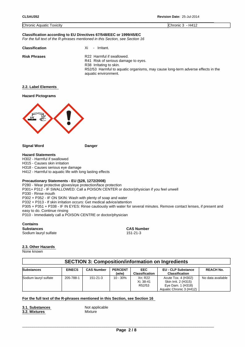
_____________________________________________________________________________________________CLSAU352 Revision Date: 25-Jul-2014
Sodium lauryl sulfate 151-21-3
Xi - Irritant.
2.3. Other Hazards
Classification according to EU Directives 67/548/EEC or 1999/45/EC
Signal Word
None known
Danger
Hazard Pictograms
SECTION 3: Composition/information on Ingredients
Risk Phrases
Hazard StatementsH302 - Harmful if swallowedH315 - Causes skin irritationH318 - Causes serious eye damageH412 - Harmful to aquatic life with long lasting effects
Substances EINECS CAS Number PERCENT(w/w)
EECClassification
EU - CLP SubstanceClassification
REACH No.
R22 Harmful if swallowed.R41 Risk of serious damage to eyes.R38 Irritating to skin.R52/53 Harmful to aquatic organisms, may cause long-term adverse effects in theaquatic environment.
Sodium lauryl sulfate 205-788-1 151-21-3 10 - 30% Xn; R22Xi; 38-41R52/53
Acute Tox. 4 (H302)Skin Irrit. 2 (H315)
Eye Dam. 1 (H318)Aquatic Chronic 3 (H412)
No data available
For the full text of the R-phrases mentioned in this Section, see Section 16
Precautionary Statements - EU (§28, 1272/2008)P280 - Wear protective gloves/eye protection/face protectionP301+ P312 - IF SWALLOWED: Call a POISON CENTER or doctor/physician if you feel unwellP330 - Rinse mouthP302 + P352 - IF ON SKIN: Wash with plenty of soap and waterP332 + P313 - If skin irritation occurs: Get medical advice/attentionP305 + P351 + P338 - IF IN EYES: Rinse cautiously with water for several minutes. Remove contact lenses, if present andeasy to do. Continue rinsingP310 - Immediately call a POISON CENTRE or doctor/physician
For the full text of the R-phrases mentioned in this Section, see Section 16
3.1. Substances Not applicable3.2. Mixtures Mixture
Contains
Chronic Aquatic Toxicity Chronic 3 - H412
Substances CAS Number
2.2. Label Elements
_____________________________________________________________________________________________
Classification
Page 2 / 8

_____________________________________________________________________________________________Revision Date: 25-Jul-2014CLSAU352
5.2. Special hazards arising from the substance or mixture
6.3. Methods and material for containment and cleaning up
Wash with soap and water. Get medical attention if irritation persists.
Special Exposure HazardsDecomposition in fire may produce toxic gases.
Do NOT spread spilled product with water. Isolate spill and stop leak where safe. Contain spill with sand or other inertmaterials. Scoop up and remove.
4.3. Indication of any immediate medical attention and special treatment needed
Inhalation
6.4. Reference to other sections
Ingestion
See Section 8 and 13 for additional information.
Notes to Physician Treat symptomatically
5.3. Advice for firefighters
SECTION 7: Handling and Storage
If swallowed, give at least 3-4 glasses of water, but do not induce vomiting. Donot give anything by mouth to an unconscious or convulsing person. Getmedical attention.
If inhaled, remove from area to fresh air. Get medical attention if respiratoryirritation develops or if breathing becomes difficult.
Special Protective Equipment for Fire-FightersFull protective clothing and approved self-contained breathing apparatus required for fire fighting personnel.
7.1. Precautions for Safe Handling
SECTION 6: Accidental release measures
Avoid breathing vapors. Wash hands after use. Launder contaminated clothing before reuse. Avoid breathing mist. Avoidcontact with eyes, skin, or clothing.
SECTION 5: Firefighting Measures
Hygiene MeasuresHandle in accordance with good industrial hygiene and safety practice
SECTION 4: First aid measures
7.2. Conditions for safe storage, including any incompatibilities
6.1. Personal precautions, protective equipment and emergency procedures
5.1. Extinguishing media
Store away from oxidizers. Keep from freezing. Keep container closed when not in use. Product has a shelf life of 24 months.
Eyes
Use appropriate protective equipment.
4.2. Most Important symptoms and effects, both acute and delayed
Suitable Extinguishing MediaWater fog, carbon dioxide, foam, dry chemical.
7.3. Specific End Use(s)
See Section 8 for additional information
In case of contact, or suspected contact, immediately flush eyes with plenty ofwater for at least 15 minutes and get medical attention immediately afterflushing.
Exposure Scenario No information available
4.1. Description of first aid measures
Extinguishing media which must not be used for safety reasonsNone known.
May cause severe eye irritation. May cause skin irritation. May be harmful if swallowed.
6.2. Environmental precautions
_____________________________________________________________________________________________Page 3 / 8
Prevent from entering sewers, waterways, or low areas.
Skin
_____________________________________________________________________________________________Revision Date: 25-Jul-2014CLSAU352
Other Guidelines
Substances CAS Number DenmarkSodium lauryl sulfate 151-21-3 Not applicable
Exposure Limits
Substances CAS Number Germany MAK/TRK Spain Portugal Finland
Derived No Effect Level (DNEL) No information available.
No information available
Worker
Sodium lauryl sulfate 151-21-3 Not applicable Not applicable
General Population
Not applicable Not applicable
Substances CAS Number
Predicted No Effect Concentration (PNEC) No information available.
EU UK OEL
8.2. Exposure controls
Substances CAS Number
Engineering Controls Use in a well ventilated area. Local exhaust ventilation should be used in areas withoutgood cross ventilation.
Austria Ireland
Personal protective equipment
Switzerland Norway
If engineering controls and work practices cannot prevent excessive exposures, the selection and proper use of personalprotective equipment should be determined by an industrial hygienist or other qualified professional based on the specificapplication of this product.
Netherlands France OEL
Sodium lauryl sulfate 151-21-3
Respiratory Protection If engineering controls and work practices cannot keep exposure below occupationalexposure limits or if exposure is unknown, wear a NIOSH certified, European StandardEN 149, AS/NZS 1715:2009, or equivalent respirator when using this product. Selectionof and instruction on using all personal protective equipment, including respirators,should be performed by an Industrial Hygienist or other qualified professional.Dust/mist respirator. (N95, P2/P3)
Not applicable Not applicable
Hand Protection Chemical-resistant protective gloves (EN 374) Suitable materials for longer, directcontact (recommended: protection index 6, corresponding to > 480 minutes permeationtime as per EN 374): Nitrile gloves. (>= 0.35 mm thickness)This information is based on literature references and on information provided by glovemanufacturers, or is derived by analogy with similar substances. Please note that inpractice the working life of chemical-resistant protective gloves may be considerablyshorter than the permeation time determined in accordance with EN 374 as a result ofthe many influencing factors (e.g. temperature). If signs of wear and tear are noticedthen the gloves should be replaced. Manufacturer's directions for use should beobserved because of great diversity of types.
Not applicable Not applicable
Skin Protection Wear impervious protective clothing, including boots, gloves, lab coat, apron, rain jacket,pants or coverall, as appropriate, to prevent skin contact.
SECTION 8: Exposure Controls/Personal Protection
8.1. Control parameters
Eye Protection Chemical goggles; also wear a face shield if splashing hazard exists.Other Precautions Eyewash fountains and safety showers must be easily accessible.
Sodium lauryl sulfate 151-21-3
Substances CAS Number
Environmental Exposure Controls No information available
Italy Poland Hungary Czech Republic
Not applicable Not applicable
SECTION 9: Physical and Chemical Properties
Sodium lauryl sulfate 151-21-3 Not applicable Not applicable Not applicable Not applicable
Not applicable
_____________________________________________________________________________________________
Not applicable
Page 4 / 8
_____________________________________________________________________________________________CLSAU352 Revision Date: 25-Jul-2014
10.4. Conditions to Avoid
Autoignition Temperature No data available
None anticipated
9.1. Information on basic physical and chemical properties
Remarks/ - Method
10.5. Incompatible Materials
Decomposition Temperature No data available
Strong oxidizers.
Flash Point No data available
10.6. Hazardous Decomposition Products
Viscosity No data available
Oxides of sulfur. Sodium oxides. Carbon monoxide and carbon dioxide.
Explosive Properties No information available
SECTION 11: Toxicological Information
Evaporation rate No data available
Oxidizing Properties No information available
11.1. Information on Toxicological Effects
pH: No data available
Acute ToxicityInhalation May cause respiratory irritation. May cause allergic respiratory reaction.
Vapor Pressure No data available
Eye Contact May cause severe eye irritation.
9.2. Other information
Skin Contact May cause an allergic skin reaction. Prolonged or repeated contact may cause skinirritation.
VOC Content (%)
Ingestion Irritation of the mouth, throat, and stomach.
No data available
Vapor Density No data available
Freezing Point/Range No data available
SECTION 10: Stability and Reactivity
Specific Gravity
Toxicology data for the components
0.98
Substances CASNumber
LD50 Oral LD50 Dermal LC50 Inhalation
Property
10.1. Reactivity
Sodium lauryl sulfate 151-21-3 1288 mg/kg (Rat)1200 mg/kg (Rat)
> 2000 mg/kg (Rabbit) (similarsubstance)
3900 mg/m3 ( Rat ) 1 h
Water Solubility Soluble in water
Not applicable
Melting Point/Range
Substances CASNumber
Skin corrosion/irritation
No data available
10.2. Chemical Stability
Sodium lauryl sulfate 151-21-3 Irritating to skin. (rabbit)
Solubility in other solvents No data available
Stable
Values
10.3. Possibility of Hazardous Reactions
Partition coefficient: n-octanol/water No data available
Will Not Occur
Boiling Point/Range 100 °C
Liquid Color: Off whiteOdor Threshold:
_____________________________________________________________________________________________
No information availableOdor:
Page 5 / 8
OdorlessPhysical State:
_____________________________________________________________________________________________CLSAU352 Revision Date: 25-Jul-2014
Sodium lauryl sulfate 151-21-3 No significant toxicity observed in animal studies at concentration requiring classification.
Mutagenic Effects
Causes severe eye irritation (rabbit)
Sodium lauryl sulfate
Sodium lauryl sulfate
Substances CASNumber
Aspiration hazard
151-21-3 In vitro tests did not show mutagenic effects In vivo tests did not show mutagenic effects. (similarsubstances)
Sodium lauryl sulfate 151-21-3 Not applicable
151-21-3 Did not cause sensitization on laboratory animals (guinea pig) (similar substances)
Eye damage/irritationSubstances
Substances CASNumber
SECTION 12: Ecological Information
Carcinogenic Effects
Sodium lauryl sulfate
12.1. Toxicity
151-21-3 Did not show carcinogenic effects in animal experiments (similar substances)
Ecotoxicity Effects
Substances CASNumber
Toxicity to Algae Toxicity to Fish Toxicity toMicroorganisms
Toxicity toInvertebrates
Sodium lauryl sulfate 151-21-3 EC50(72h): > 120 mg/L(growth rate)
(Desmodesmussubspicatus)
LC50(96h): 29 mg/L(Pimephales promelas)
LC50(96h): 4.5 mg/L(Lepomis macrochirus)NOEC(28d): < 3.8 mg/L(Pimephales promelas)
EC50(3h): 135 mg/L(activated sludge)
LC50(48h): 5.55 mg/L(Ceriodaphnia dubia)NOEC(7d): 0.88 mg/L(Ceriodaphnia dubia)
Substances CASNumber
Substances CASNumber
12.2. Persistence and degradability
Reproductive toxicity
Respiratory Sensitization
CASNumber
Sodium lauryl sulfate
Substances CAS Number Persistence and Degradability
151-21-3 No significant toxicity observed in animal studies at concentration requiring classification. (similarsubstances)
Sodium lauryl sulfate 151-21-3 Readily biodegradable (95% @ 28d)
Sodium lauryl sulfate
Sodium lauryl sulfate
12.3. Bioaccumulative potential
151-21-3 No information available
Substances CASNumber
Substances CAS Number Log Pow
STOT - single exposure
Substances
Sodium lauryl sulfate 151-21-3 <= -2.03
CASNumber
Sodium lauryl sulfate 151-21-3 No significant toxicity observed in animal studies at concentration requiring classification.
12.4. Mobility in soil No information available
Skin Sensitization
151-21-3
Substances
_____________________________________________________________________________________________
CASNumber
STOT - repeated exposure
Page 6 / 8
Substances CASNumber

_____________________________________________________________________________________________Revision Date: 25-Jul-2014CLSAU352
UN Number: Not restricted.
UN Number: Not restricted.
UN Proper Shipping Name: Not restricted
Endocrine Disruptor InformationThis product does not contain any known or suspected endocrine disruptors
Disposal Method
Transport Hazard Class(es): Not applicable
UN Proper Shipping Name:
Packing Group: Not applicable
Not restricted
Disposal should be made in accordance with federal, state, and local regulations.
Environmental hazard: Not applicable
Transport Hazard Class(es): Not applicable
Contaminated Packaging
IATA/ICAO
Packing Group:
UN Number: Not restricted.
Not applicable
Follow all applicable national or local regulations.
UN Proper Shipping Name: Not restrictedTransport Hazard Class(es): Not applicable
Environmental Hazards: Not applicable
Packing Group: Not applicableEnvironmental hazard: Not applicable
SECTION 13: Disposal Considerations
14.1. UN Number: Not restricted.
RID
SECTION 14: Transport Information
12.5. Results of PBT and vPvB assessment
14.2. UN Proper Shipping Name: Not restricted
UN Number: Not restricted.
14.3. Transport Hazard Class(es): Not applicable
UN Proper Shipping Name: Not restricted
14.4. Packing Group: Not applicable
Transport Hazard Class(es):
14.5. Environmental Hazards: Not applicable
Not applicable
14.6. Special Precautions for User: None
Packing Group: Not applicable
12.6. Other adverse effects
14.7. Transport in bulk according to Annex II of MARPOL 73/78 and the IBC Code: Not applicable
Environmental hazard: Not applicable
SECTION 15: Regulatory Information
IMDG/IMO
13.1. Waste treatment methods
_____________________________________________________________________________________________
ADR
Page 7 / 8
No information available.
_____________________________________________________________________________________________CLSAU352 Revision Date: 25-Jul-2014
R22 Harmful if swallowed.R38 Irritating to skin.R41 Risk of serious damage to eyes.R52/53 Harmful to aquatic organisms, may cause long-term adverse effects in the aquatic environment.
All components listed on inventory or are exempt.
Germany, Water EndangeringClasses (WGK)
WGK 2: Hazard to waters.
Key literature references and sources for datawww.ChemADVISOR.com/
Revision Date: 25-Jul-2014Revision NoteUpdate to Format SECTION: 8
EINECS Inventory
Legend
15.2. Chemical Safety Assessment
This safety data sheet complies with the requirements of Regulation (EC) No. 453/2010
This product, and all its components, complies with EINECS
No information available
TSCA - United States Toxic Substances Control Act Section 8(b) Inventory
Disclaimer StatementThis information is furnished without warranty, expressed or implied, as to accuracy or completeness. The information isobtained from various sources including the manufacturer and other third party sources. The information may not be validunder all conditions nor if this material is used in combination with other materials or in any process. Final determination ofsuitability of any material is the sole responsibility of the user.
15.1. Safety, health and environmental regulations/legislation specific for the substance or mixture
US TSCA Inventory
SECTION 16: Other Information
End of Safety Data Sheet
EINECS/ELINCS - European Inventory of Existing Commercial Chemical Substances/EU List of Notified Chemical Substances
All components listed on inventory or are exempt.
_____________________________________________________________________________________________
DSL/NDSL - Canadian Domestic Substances List/Non-Domestic Substances List
Full text of R-phrases referred to under Sections 2 and 3
Page 8 / 8
International Inventories
Canadian DSL Inventory
SAFETY DATA SHEETaccording to Regulation (EC) No. 453/2010
SODIUM CHLORIDERevision Date: 27-Mar-2014 Revision Number: 12
ORFILA (FR): + 01 45 42 59 59
SODIUM CHLORIDE
Germany Poison Center Berlin (DE): +49 030 30686 790
1.3 Details of the supplier of the safety data sheet
Italy Poison Center, Milan (IT): +39 02 6610 1029
Recommended Use Additive
Netherlands National Poisons Information Center (NL): +31 30 274 88 88 (NB: this service is onlyavailable to health professionals)
Halliburton Energy ServicesHalliburton House, Howemoss PlaceKirkhill Industrial EstateDyceAberdeen, AB21 0GNUnited Kingdom
Emergency Phone Number: +44 1224 795277 or +1 281 575 5000
www.halliburton.com
Norway Poisons Information (NO):+ 47 22 591300
1. Identification of the substance/mixture and of the company/undertaking
1.1 Product Identifier
Poland Poison Control and Information Centre, Warsaw (PL): +48 22 619 66 54; +48 22 619 0897
For further information, please contact
Spain Poison Information Service (ES): +34 91 562 04 20
Sector of use
E-Mail address:
United Kingdom NHS Direct (UK): +44 0845 46 47
SU2 - Mining, (including offshore industries)
1.4 Emergency telephone number
2. Hazards Identification
+44 1224 795277 or +1 281 575 5000
Product category
2.1 Classification of the substance or mixture
PC20 - Products such as pH-regulators, flocculants, precipitants, neutralization agents,other unspecific
REGULATION (EC) No 1272/2008Not classified
Emergency telephone - §45 - (EC)1272/2008
Process categories
Classification according to EU Directives 67/548/EEC or 1999/45/EC
Europe 112
PROC 26 - Handling of solid inorganic substances at ambient temperature
1.2 Relevant identified uses of the substance or mixture and uses advised against
Denmark
_____________________________________________________________________________________________
Poison Control Hotline (DK): +45 82 12 12 12
Product Name
Page 1 / 7
France

_____________________________________________________________________________________________Revision Date: 27-Mar-2014SODIUM CHLORIDE
For the full text of the R-phrases mentioned in this Section, see Section 16
4. First aid measures
Contains
4.1 Description of first aid measures
Substances CAS Number
Inhalation If inhaled, remove from area to fresh air. Get medical attention if respiratoryirritation develops or if breathing becomes difficult.
Eyes In case of contact, immediately flush eyes with plenty of water for at least 15minutes and get medical attention if irritation persists.
Sodium chloride 7647-14-5
Skin Wash with soap and water. Get medical attention if irritation persists.Ingestion Under normal conditions, first aid procedures are not required.
Signal Word None
4.2 Most Important symptoms and effects, both acute and delayed
2.3 Other Hazards
May cause eye irritation
Classification
Hazard Pictograms
None known
4.3 Indication of any immediate medical attention and special treatment needed Notes to Physician Treat symptomatically
Risk Phrases
3. Composition/information on Ingredients
Hazard StatementsNot Classified
5. Firefighting Measures
2.2 Label Elements
5.1 Extinguishing media Suitable Extinguishing MediaAll standard fire fighting media
Substances EINECS
Extinguishing media which must not be used for safety reasonsNone known.
CAS Number PERCENT(w/w)
EECClassification
EU - CLP SubstanceClassification
5.2 Special hazards arising from the substance or mixture
REACH No.
Special Exposure HazardsNot applicable.
Sodium chloride 231-598-3 7647-14-5 60 - 100% Not applicable
5.3 Advice for firefighters
Not applicable No data available
None
Precautionary Statements - EU (§28, 1272/2008)Not Classified
For the full text of the R-phrases mentioned in this Section, see Section 16
Not Classified
Not classified
_____________________________________________________________________________________________Page 2 / 7
_____________________________________________________________________________________________SODIUM CHLORIDE Revision Date: 27-Mar-2014
7647-14-5 Not applicable Not applicable Not applicable Not applicable
6.3 Methods and material for containment and cleaning up
7. Handling and Storage
7.3 Specific End Use(s)
Substances CAS Number Austria Ireland Switzerland Norway
Use appropriate protective equipment. Avoid creating and breathing dust.
Sodium chloride 7647-14-5 Not applicable Not applicable Not applicable Not applicable
Exposure Scenario No information available
Substances CAS Number Italy Poland Hungary Czech Republic
Other Guidelines No information available
Sodium chloride 7647-14-5 Not applicable Not applicable Not applicable Not applicable
Scoop up and remove.
6.2 Environmental precautions
7.1 Precautions for Safe Handling
Substances CAS Number Denmark
Special Protective Equipment for Fire-FightersNot applicable.
8. Exposure Controls/Personal Protection
Sodium chloride 7647-14-5 Not applicable
Avoid creating or inhaling dust.
6. Accidental release measures
Prevent from entering sewers, waterways, or low areas.
8.1 Control parameters
Derived No Effect Level (DNEL) No information available.
Hygiene MeasuresHandle in accordance with good industrial hygiene and safety practice
6.4 Reference to other sections
Worker
Exposure Limits
See Section 8 for additional information
General Population
Substances CAS Number EU UK OEL
Predicted No Effect Concentration (PNEC) No information available.
Netherlands France OEL
6.1 Personal precautions, protective equipment and emergency procedures
See Section 8 and 13 for additional information.
8.2 Exposure controls
Sodium chloride 7647-14-5
Engineering Controls Use in a well ventilated area.
Not applicable 10 mg/m3
Personal protective equipment
Not applicable Not applicable
Respiratory Protection Dust/mist respirator. (N95, P2/P3)
7.2 Conditions for safe storage, including any incompatibilities
Hand Protection Normal work gloves.Skin Protection Normal work coveralls.
Store in a cool, dry location.
Eye Protection Wear safety glasses or goggles to protect against exposure.
Substances CAS Number Germany MAK/TRK Spain Portugal
_____________________________________________________________________________________________
Finland
Page 3 / 7
Sodium chloride
_____________________________________________________________________________________________SODIUM CHLORIDE Revision Date: 27-Mar-2014
Not applicable
No data available
10.2 Chemical Stability
Specific Gravity
Stable
2.16
Remarks/ - Method
10.3 Possibility of Hazardous Reactions
Water Solubility
Will Not Occur
Very soluble
10.4 Conditions to Avoid
pH:
Solubility in other solvents
None anticipated
No data available
No data available
10.5 Incompatible Materials
Partition coefficient: n-octanol/water
None known.
No data available
9.1 Information on basic physical and chemical properties
10.6 Hazardous Decomposition Products
Freezing Point/Range
Autoignition Temperature
None known.
No data available
No data available
Decomposition Temperature
11. Toxicological Information
No data available
Other Precautions
Melting Point/Range
Viscosity
11.1 Information on Toxicological Effects
No data available
801 °C
Acute Toxicity
Environmental Exposure Controls
Explosive Properties
Inhalation May cause respiratory irritation.
No information available
Eye Contact May cause eye irritation
Boiling Point/Range
Oxidizing Properties
Skin Contact May cause skin irritation.
No information available
No data available
Ingestion None known
9. Physical and Chemical Properties
No information available
Chronic Effects/Carcinogenicity No data available to indicate product or components present at greater than 1% arechronic health hazards.
Flash Point
9.2 Other information
No data available
VOC Content (%) No data available
Toxicology data for the components
Evaporation rate No data available
Substances CASNumber
LD50 Oral LD50 Dermal LC50 Inhalation
10. Stability and Reactivity
Sodium chloride 7647-14-5 3 g/kg ( Rat ) 10 g/kg ( Rabbit ) 42 g/m3 ( Rat ) 1 h
None known.
Vapor Pressure No data available
Property
10.1 Reactivity
Values
Vapor Density
WhiteOdor Threshold: No information availableOdor:
_____________________________________________________________________________________________
OdorlessPhysical State:
Page 4 / 7
Solid Color:
_____________________________________________________________________________________________SODIUM CHLORIDE Revision Date: 27-Mar-2014
CASNumber
STOT - single exposure
Substances CASNumber
Sodium chloride 7647-14-5 No information available
Substances CASNumber
Respiratory Sensitization
Eye damage/irritation
Substances CASNumber
STOT - repeated exposure
Sodium chloride
Sodium chloride 7647-14-5 Not classified
7647-14-5 No information available
Sodium chloride
Sodium chloride
Substances CASNumber
Aspiration hazard
Sodium chloride 7647-14-5 Not applicable
7647-14-5 May cause mild eye irritation. (rabbit)
Substances CASNumber
Mutagenic Effects
7647-14-5 Non-irritating to the skin (rabbit)
Sodium chloride
12. Ecological Information
7647-14-5 Not regarded as mutagenic
12.1 Toxicity Ecotoxicity Effects
Substances CASNumber
Substances CASNumber
Toxicity to Algae Toxicity to Fish Toxicity toMicroorganisms
Toxicity toInvertebrates
Substances CASNumber
Sodium chloride 7647-14-5 EC50(120h): 2430 mg/L(cell number) (Nitzschia
sp.)
TLM96: > 1000 mg/l(Oncorhynchus mykiss)LC50(96h): 5840 mg/L(Lepomis macrochirus)NOEC(33d): 252 mg/L(Pimephales promelas)
EC10 </= 35000 mg/L;NOEC 5000 – 8000
mg/L (activated sludge)NOEC 292-584 mg/L
(Escherichia coli)
TLM96: > 1,000,000 ppm(Mysidopsis bahia)LC50(48h): 874 -
4136mg/L (Daphniamagna)
NOEC(21d): 314 mg/L(Daphnia pulex)
Carcinogenic Effects
Substances CASNumber
Sodium chloride
12.2 Persistence and degradability
7647-14-5 Did not show carcinogenic effects in animal experiments
The methods for determining biodegradability are not applicable to inorganic substances.
Skin Sensitization
Substances CAS Number Persistence and DegradabilitySodium chloride 7647-14-5 No information available
Sodium chloride
Substances CASNumber
12.3 Bioaccumulative potential
Reproductive Toxicity
7647-14-5
Does not bioaccumulate
No information available
Sodium chloride
Substances CAS Number Log Pow
7647-14-5 Not a confirmed reproductive toxicant.
Skin corrosion/irritation
_____________________________________________________________________________________________Page 5 / 7
Substances
_____________________________________________________________________________________________SODIUM CHLORIDE Revision Date: 27-Mar-2014
Packing Group: Not applicableEnvironmental hazard: Not applicable
7647-14-5
ADR
13. Disposal Considerations
No information available.
UN Number: Not restricted.
IMDG/IMO
UN Proper Shipping Name: Not restricted
No information available
Transport Hazard Class(es): Not applicable
UN Number:
Packing Group: Not applicable
Not restricted.
Environmental hazard: Not applicable
UN Proper Shipping Name: Not restricted
13.1 Waste treatment methods
IATA/ICAO
Transport Hazard Class(es):
UN Number: Not restricted.
Not applicable
UN Proper Shipping Name: Not restricted
No information available
Transport Hazard Class(es): Not applicable
Packing Group: Not applicable
Packing Group: Not applicable
Disposal Method Bury in a licensed landfill according to federal, state, and local regulations.
Environmental hazard: Not applicable
Environmental Hazards: Not applicable
Special Precautions for User None
12.6 Other adverse effects
Transport in bulk according to Annex II of MARPOL 73/78 and the IBC Code Not applicable
Contaminated Packaging Follow all applicable national or local regulations. Contaminated packaging may bedisposed of by: rendering packaging incapable of containing any substance, or treatingpackaging to remove residual contents, or treating packaging to make sure the residualcontents are no longer hazardous, or by disposing of packaging into commercial wastecollection.
RID
15. Regulatory Information
Sodium chloride
15.1 Safety, health and environmental regulations/legislation specific for the substance or mixture
UN Number: Not restricted.
Endocrine Disruptor InformationThis product does not contain any known or suspected endocrine disruptors
International Inventories
UN Proper Shipping Name: Not restricted
12.4 Mobility in soil
14. Transport Information
_____________________________________________________________________________________________
Transport Hazard Class(es):
Page 6 / 7
Not applicable
12.5 Results of PBT and vPvB assessment
_____________________________________________________________________________________________SODIUM CHLORIDE Revision Date: 27-Mar-2014
Key literature references and sources for datawww.ChemADVISOR.com/NZ CCID
Canadian DSL Inventory
TSCA - United States Toxic Substances Control Act Section 8(b) Inventory
Revision Date: 27-Mar-2014
All components listed on inventory or are exempt.
EINECS Inventory
Revision Note
15.2 Chemical Safety Assessment
EINECS/ELINCS - European Inventory of Existing Commercial Chemical Substances/EU List of Notified Chemical Substances
Not applicable
US TSCA Inventory
No information available
DSL/NDSL - Canadian Domestic Substances List/Non-Domestic Substances List
This safety data sheet complies with the requirements of Regulation (EC) No. 453/2010
All components listed on inventory or are exempt.
16. Other Information
Disclaimer StatementThis information is furnished without warranty, expressed or implied, as to accuracy or completeness. The information isobtained from various sources including the manufacturer and other third party sources. The information may not be validunder all conditions nor if this material is used in combination with other materials or in any process. Final determination ofsuitability of any material is the sole responsibility of the user.
End of Safety Data Sheet
This product, and all its components, complies with EINECS
Legend
Full text of R-phrases referred to under Sections 2 and 3
Germany, Water EndangeringClasses (WGK)
WGK 0: Generally not water endangering.
_____________________________________________________________________________________________Page 7 / 7
All of the components in the product are on the following Inventory lists: All of the components in the product are on thefollowing Inventory lists:.

SAFETY DATA SHEETaccording to Regulation (EC) No. 453/2010
CLLAU302Revision Date: 05-Aug-2014 Revision Number: 2
ORFILA (FR): + 01 45 42 59 59
CLLAU302
Germany Poison Center Berlin (DE): +49 030 30686 790
1.3. Details of the supplier of the safety data sheet
Italy Poison Center, Milan (IT): +39 02 6610 1029
Recommended Use Crosslinker
Netherlands National Poisons Information Center (NL): +31 30 274 88 88 (NB: this service is onlyavailable to health professionals)
Halliburton Energy ServicesHalliburton House, Howemoss PlaceKirkhill Industrial EstateDyceAberdeen, AB21 0GNUnited Kingdom
Emergency Phone Number: +44 1224 795277 or +1 281 575 5000
www.halliburton.com
Norway Poisons Information (NO):+ 47 22 591300
SECTION 1: Identification of the substance/mixture and of the company/undertaking
1.1. Product Identifier
Poland Poison Control and Information Centre, Warsaw (PL): +48 22 619 66 54; +48 22 619 0897
For further information, please contact
Spain Poison Information Service (ES): +34 91 562 04 20
Sector of use
E-Mail address:
United Kingdom NHS Direct (UK): +44 0845 46 47
SU2 - Mining, (including offshore industries)
1.4. Emergency telephone number
SECTION 2: Hazards Identification
+44 1224 795277 or +1 281 575 5000
Product category
2.1. Classification of the substance or mixture
PC20 - Products such as pH-regulators, flocculants, precipitants, neutralization agents,other unspecific
REGULATION (EC) No 1272/2008Not classified
Emergency telephone - §45 - (EC)1272/2008
Process categories
Classification according to EU Directives 67/548/EEC or 1999/45/EC
Europe 112
PROC4 - Use in batch and other process (synthesis) where opportunity for exposurearises
1.2. Relevant identified uses of the substance or mixture and uses advised against
Denmark
_____________________________________________________________________________________________
Poison Control Hotline (DK): +45 82 12 12 12
Product Name
Page 1 / 8
France

_____________________________________________________________________________________________Revision Date: 05-Aug-2014CLLAU302
For the full text of the R-phrases mentioned in this Section, see Section 16
For the full text of the R-phrases mentioned in this Section, see Section 16
Contains
3.1. Substances Not applicable3.2. Mixtures Not applicable
Substances CAS Number
SECTION 4: First aid measures
Sulfuric acid 7664-93-9
4.1. Description of first aid measures Inhalation If inhaled, remove from area to fresh air. Get medical attention if respiratory
irritation develops or if breathing becomes difficult.
Signal Word None
Eyes Immediately flush eyes with large amounts of water for at least 15 minutes. Getimmediate medical attention.
Skin Wash with soap and water. Get medical attention if irritation persists.
Classification
Hazard Pictograms
Ingestion Under normal conditions, first aid procedures are not required.
2.3. Other Hazards
4.2. Most Important symptoms and effects, both acute and delayed
None known
No information available
Risk Phrases
Hazard StatementsNot Classified
2.2. Label Elements
4.3. Indication of any immediate medical attention and special treatment needed
SECTION 3: Composition/information on Ingredients
Notes to Physician Treat symptomatically
SECTION 5: Firefighting Measures
Substances EINECS
5.1. Extinguishing media
CAS Number PERCENT(w/w)
Suitable Extinguishing MediaWater fog, carbon dioxide, foam, dry chemical.
EECClassification
EU - CLP SubstanceClassification
Extinguishing media which must not be used for safety reasonsNone known.
REACH No.
None
Precautionary Statements - EU (§28, 1272/2008)None
Sulfuric acid
5.2. Special hazards arising from the substance or mixture
231-639-5 7664-93-9 1 - 5% C; R35 Skin Corr. 1A (H314) No data available
Not Classified
_____________________________________________________________________________________________
Not classified
Page 2 / 8
_____________________________________________________________________________________________CLLAU302 Revision Date: 05-Aug-2014
Sulfuric acid 7664-93-9 Not applicable 0.3 mg/m3 0.05 mg/m3 1 mg/m3
Substances CAS Number Germany MAK/TRK Spain Portugal Finland
7.2. Conditions for safe storage, including any incompatibilities
Sulfuric acid 7664-93-9 MAK: 0.1 mg/m3 3 mg/m3 VLA-ECVLA-ED: 1 mg/m3
TWA: 0.2 mg/m3 STEL: 1 mg/m3
TWA: 0.2 mg/m3
6.4. Reference to other sections
Store away from oxidizers. Store in a dry location.
Substances CAS Number Austria Ireland Switzerland Norway
6.2. Environmental precautions
Sulfuric acid 7664-93-9 Not applicable Not applicable Not applicable STEL: 0.3 mg/m3
TWA: 0.1 mg/m3
See Section 8 and 13 for additional information.
Special Protective Equipment for Fire-FightersFull protective clothing and approved self-contained breathing apparatus required for fire fighting personnel.
7.3. Specific End Use(s)
6.1. Personal precautions, protective equipment and emergency procedures
Substances CAS Number Italy Poland Hungary Czech Republic
Exposure Scenario
Sulfuric acid 7664-93-9 Not applicable NDSCh: 3 mg/m3
NDS: 1 mg/m3
TWA: 1 mg/m3
STEL: 1 mg/m3
TWA: 1 mg/m3
No information available
Prevent from entering sewers, waterways, or low areas.
Special Exposure HazardsDecomposition in fire may produce toxic gases.
Other Guidelines
Substances CAS Number Denmark
No information available
SECTION 7: Handling and Storage
Sulfuric acid 7664-93-9 TWA: 1 mg/m3
SECTION 8: Exposure Controls/Personal Protection
Use appropriate protective equipment.
Derived No Effect Level (DNEL) No information available.
SECTION 6: Accidental release measures
7.1. Precautions for Safe Handling
Worker
8.1. Control parameters
6.3. Methods and material for containment and cleaning up
5.3. Advice for firefighters
Exposure Limits
General Population
Avoid breathing mist.
See Section 8 for additional information
Substances CAS Number EU UK OEL
_____________________________________________________________________________________________
Netherlands France OEL
Page 3 / 8
Contain spill with sand or other inert materials. Scoop up and remove.
Hygiene MeasuresHandle in accordance with good industrial hygiene and safety practice
_____________________________________________________________________________________________Revision Date: 05-Aug-2014CLLAU302
Impervious rubber gloves.
Vapor Density No data availableSpecific Gravity 1.25
8.2. Exposure controls
9.1. Information on basic physical and chemical properties
Water Solubility Soluble in water
Skin Protection
Solubility in other solvents No data available
Normal work coveralls.
Partition coefficient: n-octanol/water No data availableAutoignition Temperature No data availableDecomposition Temperature No data available
Eye Protection Wear safety glasses or goggles to protect against exposure.
Viscosity No data available
If engineering controls and work practices cannot prevent excessive exposures, the selection and proper use of personalprotective equipment should be determined by an industrial hygienist or other qualified professional based on the specificapplication of this product.
Explosive Properties No information availableOxidizing Properties No information available
Other Precautions Eyewash fountains and safety showers must be easily accessible.
Engineering Controls
9.2. Other information VOC Content (%) No data available
Property Values
SECTION 10: Stability and Reactivity
Use in a well ventilated area.
Remarks/ - Method
Predicted No Effect Concentration (PNEC)
10.1. Reactivity
Environmental Exposure Controls
pH:
Not applicable
4.15
No information available
10.2. Chemical Stability
Freezing Point/Range
Stable
No data available
Respiratory Protection
10.3. Possibility of Hazardous Reactions
Melting Point/Range
Will Not Occur
No data available
10.4. Conditions to Avoid
If engineering controls and work practices cannot keep exposure below occupationalexposure limits or if exposure is unknown, wear a NIOSH certified, European StandardEN 149, AS/NZS 1715:2009, or equivalent respirator when using this product. Selectionof and instruction on using all personal protective equipment, including respirators,should be performed by an Industrial Hygienist or other qualified professional.Not normally needed. But if significant exposures are possible then the followingrespirator is recommended:Dust/mist respirator. (N95, P2/P3)
Boiling Point/Range
None anticipated
No data available
No information available.
10.5. Incompatible Materials
Flash Point
Strong oxidizers.
No data available
Personal protective equipment
Evaporation rate No data available
SECTION 9: Physical and Chemical Properties
Hand Protection
Vapor Pressure No data available
White to yellowOdor Threshold: No information availableOdor:
_____________________________________________________________________________________________
OdorlessPhysical State:
Page 4 / 8
Liquid Color:

_____________________________________________________________________________________________CLLAU302 Revision Date: 05-Aug-2014
Chronic Effects/Carcinogenicity
Sulfuric acid 7664-93-9 Corrosive to eyes (rabbit)
No data available to indicate product or components present at greater than 1% arechronic health hazards.
Inhalation May cause respiratory irritation.
Substances CASNumber
Skin Sensitization
Carbon monoxide and carbon dioxide.
Sulfuric acid 7664-93-9 No information available
SECTION 11: Toxicological Information
Substances CASNumber
Respiratory Sensitization
Eye Contact
Toxicology data for the components
Sulfuric acid 7664-93-9 No information available
May cause eye irritation
11.1. Information on Toxicological Effects
Substances CASNumber
Mutagenic Effects
Sulfuric acid 7664-93-9 Not regarded as mutagenic.
Substances CASNumber
LD50 Oral LD50 Dermal
Substances CASNumber
Carcinogenic Effects
LC50 Inhalation
Skin Contact
Sulfuric acid 7664-93-9 Contains sulfuric acid, a potential carcinogen.
May cause skin irritation.
Sulfuric acid 7664-93-9 2140 mg/kg ( Rat )
Substances CASNumber
Reproductive toxicity
No data available 347 ppm ( Rat ) 1 h510 mg/m3 ( Rat ) 2 h295 mg/m3 (Rat) 4h375 mg/m3 (Rat) 4h
160 mg/m3 (Mouse) 4h15 mg/m3 (Guinea pig) 4h9 mg/m3 (Guinea pig) 4h
Sulfuric acid 7664-93-9 No significant toxicity observed in animal studies at concentration requiring classification. Did notshow teratogenic effects in animal experiments.
10.6. Hazardous Decomposition Products
Acute Toxicity
Substances CASNumber
STOT - single exposure
Ingestion
Sulfuric acid 7664-93-9 No significant toxicity observed in animal studies at concentration requiring classification.
Substances CASNumber
Skin corrosion/irritation
None known
Substances CASNumber
STOT - repeated exposure
Sulfuric acid
Sulfuric acid 7664-93-9 No significant toxicity observed in animal studies at concentration requiring classification.
7664-93-9 Corrosive to skin (rabbit)
_____________________________________________________________________________________________
Substances
Page 5 / 8
CASNumber
Eye damage/irritation

_____________________________________________________________________________________________CLLAU302 Revision Date: 05-Aug-2014
SECTION 12: Ecological Information
12.5. Results of PBT and vPvB assessment No information available.
12.2. Persistence and degradability
Substances PBT and vPvB assessmentSulfuric acid Not PBT/vPvB
CASNumber
Sulfuric acid
Substances CAS Number
12.6. Other adverse effects
Persistence and Degradability
12.1. Toxicity
Endocrine Disruptor InformationThis product does not contain any known or suspected endocrine disruptors
Sulfuric acid 7664-93-9 The methods for determining biodegradability arenot applicable to inorganic substances.
SECTION 13: Disposal Considerations
Ecotoxicity Effects
13.1. Waste treatment methods
7664-93-9 Not applicable
Disposal Method Bury in a licensed landfill according to federal, state, and local regulations.
12.3. Bioaccumulative potential
Substances
Contaminated Packaging Follow all applicable national or local regulations.
CASNumber
Toxicity to Algae Toxicity to Fish
SECTION 14: Transport Information
Substances CAS Number Log Pow
Toxicity toMicroorganisms
Toxicity toInvertebrates
Sulfuric acid
IMDG/IMO
7664-93-9 No information available
UN Number: Not restricted.
Aspiration hazard
UN Proper Shipping Name: Not restrictedTransport Hazard Class(es): Not applicable
Sulfuric acid 7664-93-9
Packing Group: Not applicable
12.4. Mobility in soil
EC50(72h): > 100 mg/L(growth rate)
(Desmodesmussubspicatus)
LC50: >500 mg/l(Brachydanio rerio)
LC50(96h) > 16 and < 28mg/L (Lepomismacrochirus)
NOEC(65d): 0.025 mg/L(fry growth) (Jordanella
floridae)NOEC(chronic): 0.31
mg/L (larvaldevelopment)
(Salvelinus fontinalis)
No information available
NOEC(21d): 6.61 pH(total bacteria)
NOEC(37d): ca. 26 g/L(activated sludge,
respiration rate) (Similarsubstance)
_____________________________________________________________________________________________
EC50(48h): 29 mg/L(Daphnia magna)
EC50(48h): > 100 mg/L(Daphnia magna)
NOEL(chronic): 0.15mg/L (mortality)
(Tanytarsus dissimilis)
Page 6 / 8
Substances
_____________________________________________________________________________________________CLLAU302 Revision Date: 05-Aug-2014
Transport Hazard Class(es): Not applicable
Transport Hazard Class(es):
14.4. Packing Group: Not applicable
Not applicable
Packing Group: Not applicable
14.5. Environmental Hazards: Not applicable
Environmental Hazards:
Environmental hazard:
14.6. Special Precautions for User: None
Not applicable
Packing Group:
14.7. Transport in bulk according to Annex II of MARPOL 73/78 and the IBC Code: Not applicable
Not applicable
SECTION 15: Regulatory Information
IATA/ICAO
15.1. Safety, health and environmental regulations/legislation specific for the substance or mixture
Environmental hazard: Not applicable
International Inventories
UN Number: Not restricted.
EINECS Inventory This product, and all its components, complies with EINECS
UN Number: Not restricted.
US TSCA Inventory All components listed on inventory or are exempt.
UN Proper Shipping Name:
Canadian DSL Inventory All components listed on inventory or are exempt.
Not restricted
Legend
Transport Hazard Class(es): Not applicable
TSCA - United States Toxic Substances Control Act Section 8(b) Inventory
Not applicable
EINECS/ELINCS - European Inventory of Existing Commercial Chemical Substances/EU List of Notified Chemical Substances
Packing Group:
DSL/NDSL - Canadian Domestic Substances List/Non-Domestic Substances List
Not applicable
ADR
Germany, Water EndangeringClasses (WGK)
WGK 1: Low hazard to waters.
Environmental hazard: Not applicable
UN Proper Shipping Name:
15.2. Chemical Safety Assessment
UN Number:
No information available
14.1. UN Number: Not restricted.
Not restricted.
Not restricted
SECTION 16: Other Information
Full text of R-phrases referred to under Sections 2 and 3
14.2. UN Proper Shipping Name: Not restricted
R34 Causes burns.
UN Proper Shipping Name: Not restricted
RID
_____________________________________________________________________________________________
14.3. Transport Hazard Class(es):
Page 7 / 8
Not applicable

_____________________________________________________________________________________________CLLAU302 Revision Date: 05-Aug-2014
05-Aug-2014
Key literature references and sources for datawww.ChemADVISOR.com/
Disclaimer StatementThis information is furnished without warranty, expressed or implied, as to accuracy or completeness. The information isobtained from various sources including the manufacturer and other third party sources. The information may not be validunder all conditions nor if this material is used in combination with other materials or in any process. Final determination ofsuitability of any material is the sole responsibility of the user.
Revision Note
End of Safety Data Sheet
Not applicable
_____________________________________________________________________________________________
Full text of H-Statements referred to under sections 2 and 3H314 - Causes severe skin burns and eye damage
Page 8 / 8
This safety data sheet complies with the requirements of Regulation (EC) No. 453/2010
Revision Date:
SAFETY DATA SHEETaccording to Regulation (EC) No. 453/2010
CLLAU303Revision Date: 05-Aug-2014 Revision Number: 2
ORFILA (FR): + 01 45 42 59 59
CLLAU303
Germany Poison Center Berlin (DE): +49 030 30686 790
1.3. Details of the supplier of the safety data sheet
Italy Poison Center, Milan (IT): +39 02 6610 1029
Recommended Use Crosslinker
Netherlands National Poisons Information Center (NL): +31 30 274 88 88 (NB: this service is onlyavailable to health professionals)
Halliburton Energy ServicesHalliburton House, Howemoss PlaceKirkhill Industrial EstateDyceAberdeen, AB21 0GNUnited Kingdom
Emergency Phone Number: +44 1224 795277 or +1 281 575 5000
www.halliburton.com
Norway Poisons Information (NO):+ 47 22 591300
SECTION 1: Identification of the substance/mixture and of the company/undertaking
1.1. Product Identifier
Poland Poison Control and Information Centre, Warsaw (PL): +48 22 619 66 54; +48 22 619 0897
For further information, please contact
Spain Poison Information Service (ES): +34 91 562 04 20
Sector of use
E-Mail address:
United Kingdom NHS Direct (UK): +44 0845 46 47
SU2 - Mining, (including offshore industries)
1.4. Emergency telephone number
SECTION 2: Hazards Identification
+44 1224 795277 or +1 281 575 5000
Product category
2.1. Classification of the substance or mixture
PC20 - Products such as pH-regulators, flocculants, precipitants, neutralization agents,other unspecific
REGULATION (EC) No 1272/2008Serious Eye Damage / Eye Irritation Category 1 - (H318)
Emergency telephone - §45 - (EC)1272/2008
Process categories
Classification according to EU Directives 67/548/EEC or 1999/45/EC
Europe 112
PROC4 - Use in batch and other process (synthesis) where opportunity for exposurearises
1.2. Relevant identified uses of the substance or mixture and uses advised against
Denmark
_____________________________________________________________________________________________
Poison Control Hotline (DK): +45 82 12 12 12
Product Name
Page 1 / 7
France
_____________________________________________________________________________________________CLLAU303 Revision Date: 05-Aug-2014
Substances EINECS CAS Number PERCENT(w/w)
EECClassification
EU - CLP SubstanceClassification
REACH No.
Precautionary Statements - EU (§28, 1272/2008)P280 - Wear protective glovesP305 + P351 + P338 - IF IN EYES: Rinse cautiously with water for several minutes. Remove contact lenses, if present andeasy to do. Continue rinsingP310 - Immediately call a POISON CENTER or doctor/physician
Aluminum sulfateoctadecahydrate
616-524-3 7784-31-8 30 - 60% R37/38-41 Eye Dam. 1 (H318) No data available
For the full text of the R-phrases mentioned in this Section, see Section 16
For the full text of the R-phrases mentioned in this Section, see Section 16
Contains
3.1. Substances Not applicable
Hazard Pictograms
3.2. Mixtures Not applicable
Substances CAS Number
SECTION 4: First aid measures
Aluminum sulfate octadecahydrate 7784-31-8
Classification
4.1. Description of first aid measures Inhalation If inhaled, remove from area to fresh air. Get medical attention if respiratory
irritation develops or if breathing becomes difficult.
Signal Word Danger
Eyes Immediately flush eyes with large amounts of water for at least 15 minutes. Getimmediate medical attention.
Skin Wash with soap and water. Get medical attention if irritation persists.Ingestion Do not induce vomiting. Slowly dilute with 1-2 glasses of water or milk and
seek medical attention. Never give anything by mouth to an unconsciousperson.
2.3. Other Hazards
4.2. Most Important symptoms and effects, both acute and delayed
None known
Risk Phrases
2.2. Label Elements
Hazard StatementsH318 - Causes serious eye damage
R41 Risk of serious damage to eyes.R37/38 Irritating to respiratory system and skin.
SECTION 3: Composition/information on Ingredients
Xi - Irritant.
_____________________________________________________________________________________________Page 2 / 7
_____________________________________________________________________________________________CLLAU303 Revision Date: 05-Aug-2014
Store in a cool, dry location. Product has a shelf life of 24 months.
Special Protective Equipment for Fire-FightersNot applicable.
Notes to Physician
6.3. Methods and material for containment and cleaning up
7.3. Specific End Use(s)
Treat symptomatically
SECTION 6: Accidental release measures
Exposure Scenario No information available
Isolate spill and stop leak where safe. Neutralize with lime slurry, limestone, or soda ash. Contain spill with sand or other inertmaterials. Scoop up and remove.
5.2. Special hazards arising from the substance or mixture
Other Guidelines No information available
5.1. Extinguishing media
SECTION 8: Exposure Controls/Personal Protection
6.4. Reference to other sections
Special Exposure HazardsNot applicable.
See Section 8 and 13 for additional information.
8.1. Control parameters
6.1. Personal precautions, protective equipment and emergency procedures
4.3. Indication of any immediate medical attention and special treatment needed
Exposure Limits
Suitable Extinguishing MediaAll standard fire fighting media
Substances CAS Number EU UK OEL Netherlands France OEL
Use appropriate protective equipment.
SECTION 7: Handling and Storage
Aluminum sulfateoctadecahydrate
7784-31-8 Not applicable STEL: 6 mg/m3
TWA: 2 mg/m3
Not applicable Not applicable
Substances CAS Number Germany MAK/TRK Spain Portugal Finland
See Section 8 for additional information
Aluminum sulfateoctadecahydrate
7784-31-8 Not applicable VLA-ED: 2 mg/m3 TWA: 2 mg/m3 TWA: 1 mg/m3
7.1. Precautions for Safe Handling Avoid contact with eyes, skin, or clothing. Avoid breathing mist.
Substances CAS Number Austria Ireland Switzerland Norway
Extinguishing media which must not be used for safety reasonsNone known.
Aluminum sulfateoctadecahydrate
7784-31-8 Not applicable Not applicable Not applicable STEL: 4 mg/m3
TWA: 2 mg/m3
Hygiene MeasuresHandle in accordance with good industrial hygiene and safety practice
6.2. Environmental precautions
No information available
5.3. Advice for firefighters
_____________________________________________________________________________________________
Prevent from entering sewers, waterways, or low areas.
7.2. Conditions for safe storage, including any incompatibilities
Page 3 / 7
SECTION 5: Firefighting Measures
_____________________________________________________________________________________________CLLAU303 Revision Date: 05-Aug-2014
Italy Poland
General Population
SECTION 9: Physical and Chemical Properties
Substances CAS Number
9.1. Information on basic physical and chemical properties
Denmark
Hungary
Predicted No Effect Concentration (PNEC) No information available.
Czech Republic
Aluminum sulfate octadecahydrate 7784-31-8 TWA: 1 mg/m3
8.2. Exposure controls Engineering Controls Use in a well ventilated area.
Property Values
Personal protective equipment
Remarks/ - Method
Aluminum sulfateoctadecahydrate
pH: 1.55
7784-31-8
Freezing Point/Range No data available
If engineering controls and work practices cannot prevent excessive exposures, the selection and proper use of personalprotective equipment should be determined by an industrial hygienist or other qualified professional based on the specificapplication of this product.
Melting Point/Range No data availableBoiling Point/Range No data available
Not applicable Not applicable
Flash Point No data available
Respiratory Protection
Evaporation rate No data available
If engineering controls and work practices cannot keep exposure below occupationalexposure limits or if exposure is unknown, wear a NIOSH certified, European StandardEN 149, AS/NZS 1715:2009, or equivalent respirator when using this product. Selectionof and instruction on using all personal protective equipment, including respirators,should be performed by an Industrial Hygienist or other qualified professional.Not normally needed. But if significant exposures are possible then the followingrespirator is recommended:Dust/mist respirator. (N95, P2/P3)
Vapor Pressure No data availableVapor Density No data available
Hand Protection Impervious rubber gloves.
Specific Gravity 1.3
Not applicable Not applicable
Water Solubility Soluble in water
Skin Protection
Solubility in other solvents No data available
Normal work coveralls.
Derived No Effect Level (DNEL)
Partition coefficient: n-octanol/water No data available
No information available.
Autoignition Temperature No data available
Eye Protection Wear safety glasses or goggles to protect against exposure.
Decomposition Temperature No data available
Substances CAS Number
Viscosity No data available
Other Precautions
Explosive Properties No information available
None known.
Worker
Oxidizing Properties No information available
Environmental Exposure Controls No information available
Odor Threshold: No information availableOdor: Odorless
_____________________________________________________________________________________________
Physical State: Liquid
Page 4 / 7
Color: White
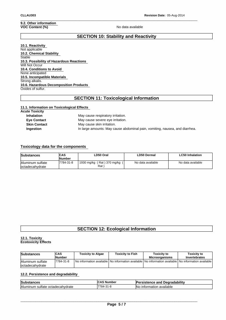
_____________________________________________________________________________________________Revision Date: 05-Aug-2014CLLAU303
Acute Toxicity
Stable
9.2. Other information
Inhalation May cause respiratory irritation.
Strong alkalis.
10.1. Reactivity
Eye Contact May cause severe eye irritation.
10.3. Possibility of Hazardous Reactions
10.6. Hazardous Decomposition Products
Skin Contact May cause skin irritation.
SECTION 10: Stability and Reactivity
VOC Content (%)
Ingestion In large amounts: May cause abdominal pain, vomiting, nausea, and diarrhea.
Oxides of sulfur.
Will Not Occur
SECTION 12: Ecological Information
Not applicable
12.1. Toxicity
10.4. Conditions to Avoid
Ecotoxicity Effects
Substances CASNumber
Toxicity to Algae Toxicity to Fish Toxicity toMicroorganisms
Toxicity toInvertebrates
SECTION 11: Toxicological Information
Aluminum sulfateoctadecahydrate
7784-31-8 No information available No information available No information available No information available
Toxicology data for the components
10.2. Chemical Stability
12.2. Persistence and degradability
None anticipated
Substances
Substances CAS Number Persistence and Degradability
CASNumber
LD50 Oral
Aluminum sulfate octadecahydrate 7784-31-8 No information available
LD50 Dermal LC50 Inhalation
11.1. Information on Toxicological Effects
Aluminum sulfateoctadecahydrate
7784-31-8 1930 mg/kg ( Rat ) 370 mg/kg (Rat )
_____________________________________________________________________________________________
No data available No data available
Page 5 / 7
No data available
10.5. Incompatible Materials
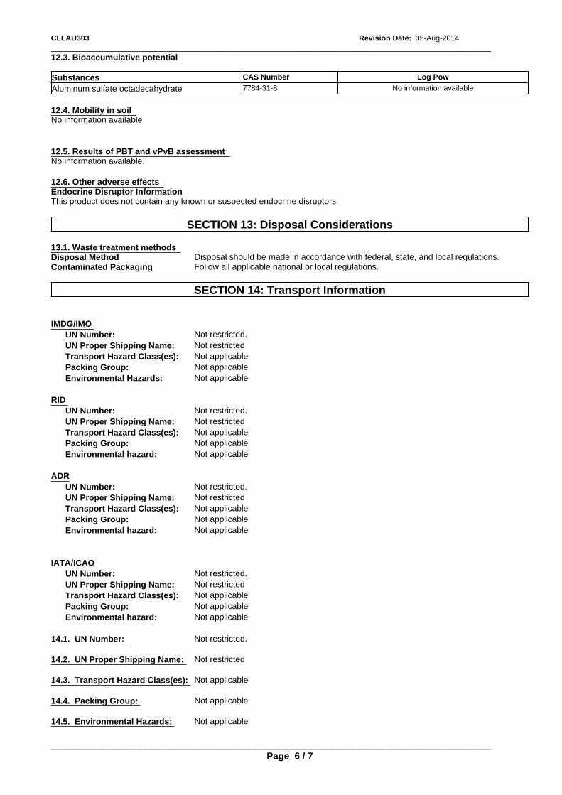
_____________________________________________________________________________________________CLLAU303 Revision Date: 05-Aug-2014
Contaminated Packaging
Transport Hazard Class(es): Not applicable
Follow all applicable national or local regulations.
12.4. Mobility in soil
Packing Group: Not applicableEnvironmental hazard: Not applicable
SECTION 14: Transport Information
Aluminum sulfate octadecahydrate
ADR
No information available
UN Number: Not restricted.
12.6. Other adverse effects
UN Proper Shipping Name: Not restricted
7784-31-8
Transport Hazard Class(es): Not applicable
No information available
Packing Group: Not applicable
Endocrine Disruptor InformationThis product does not contain any known or suspected endocrine disruptors
IMDG/IMO
Environmental hazard: Not applicable
UN Number: Not restricted.
IATA/ICAO
Substances
UN Number: Not restricted.
UN Proper Shipping Name:
UN Proper Shipping Name: Not restricted
Not restricted
CAS Number
Transport Hazard Class(es): Not applicable
SECTION 13: Disposal Considerations
Packing Group: Not applicable
Transport Hazard Class(es): Not applicable
Environmental hazard: Not applicable
Packing Group:
14.1. UN Number: Not restricted.
Not applicable
14.2. UN Proper Shipping Name: Not restricted
Environmental Hazards: Not applicable
14.3. Transport Hazard Class(es): Not applicable
13.1. Waste treatment methods
12.5. Results of PBT and vPvB assessment
14.4. Packing Group: Not applicable
RID
Log Pow
Disposal Method
14.5. Environmental Hazards: Not applicable
UN Number: Not restricted.
Disposal should be made in accordance with federal, state, and local regulations.
12.3. Bioaccumulative potential
_____________________________________________________________________________________________
UN Proper Shipping Name:
Page 6 / 7
Not restricted
No information available.
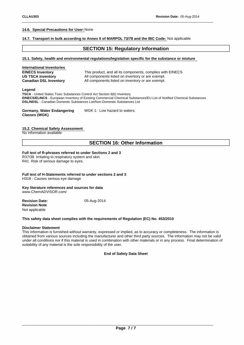
_____________________________________________________________________________________________Revision Date: 05-Aug-2014CLLAU303
15.1. Safety, health and environmental regulations/legislation specific for the substance or mixture
Legend
Full text of R-phrases referred to under Sections 2 and 3R37/38 Irritating to respiratory system and skin.R41 Risk of serious damage to eyes.
TSCA - United States Toxic Substances Control Act Section 8(b) Inventory
Full text of H-Statements referred to under sections 2 and 3H318 - Causes serious eye damage
EINECS/ELINCS - European Inventory of Existing Commercial Chemical Substances/EU List of Notified Chemical Substances
International Inventories
DSL/NDSL - Canadian Domestic Substances List/Non-Domestic Substances List
Key literature references and sources for datawww.ChemADVISOR.com/
Revision Date: 05-Aug-2014
SECTION 15: Regulatory Information
EINECS Inventory
Revision Note
Germany, Water EndangeringClasses (WGK)
WGK 1: Low hazard to waters.
Not applicable
This product, and all its components, complies with EINECS
14.6. Special Precautions for User:
This safety data sheet complies with the requirements of Regulation (EC) No. 453/2010
None
US TSCA Inventory
Disclaimer StatementThis information is furnished without warranty, expressed or implied, as to accuracy or completeness. The information isobtained from various sources including the manufacturer and other third party sources. The information may not be validunder all conditions nor if this material is used in combination with other materials or in any process. Final determination ofsuitability of any material is the sole responsibility of the user.
All components listed on inventory or are exempt.
15.2. Chemical Safety Assessment
End of Safety Data Sheet
Canadian DSL Inventory
No information available
All components listed on inventory or are exempt.
14.7. Transport in bulk according to Annex II of MARPOL 73/78 and the IBC Code:
_____________________________________________________________________________________________
Not applicable
Page 7 / 7
SECTION 16: Other Information
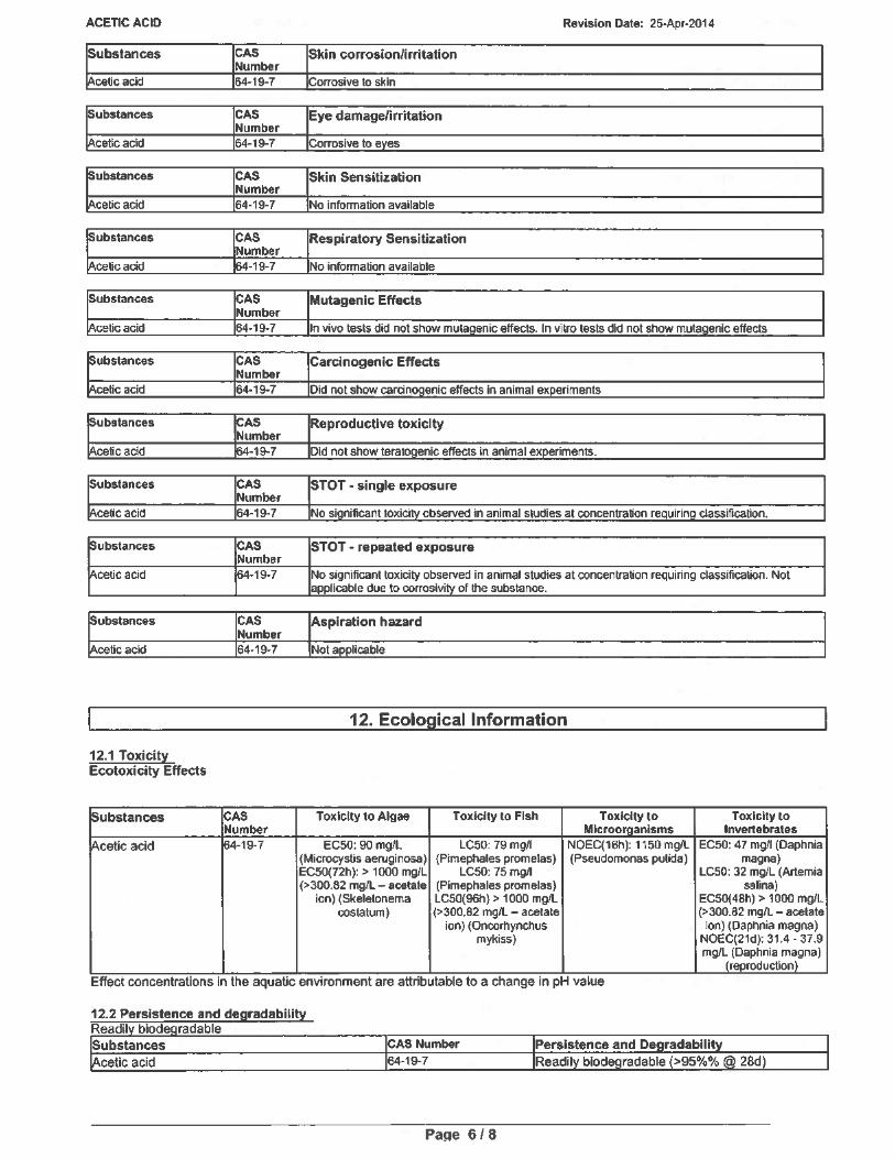
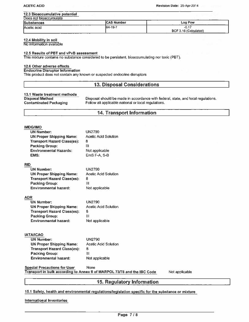
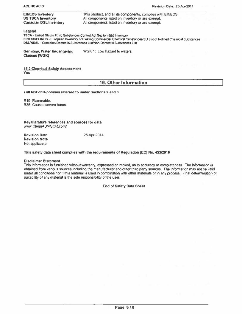
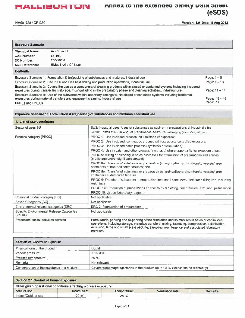
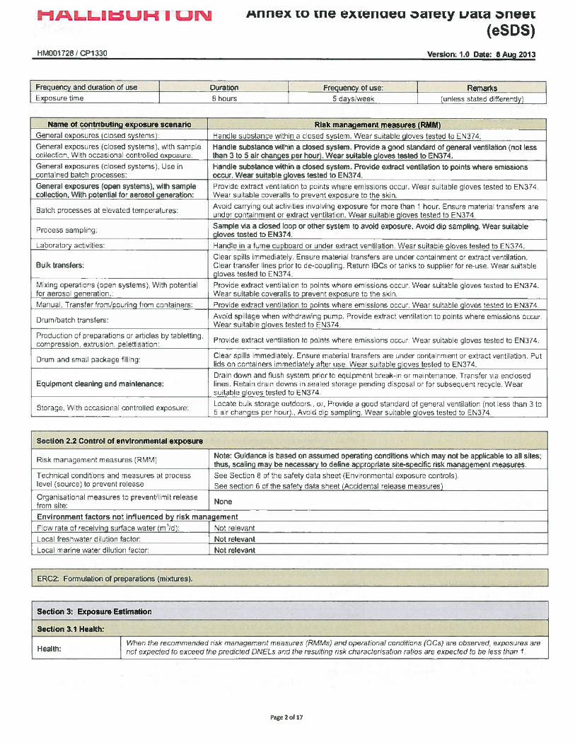
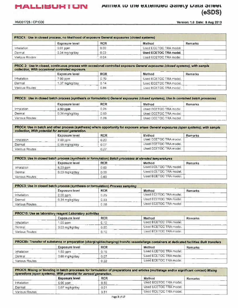
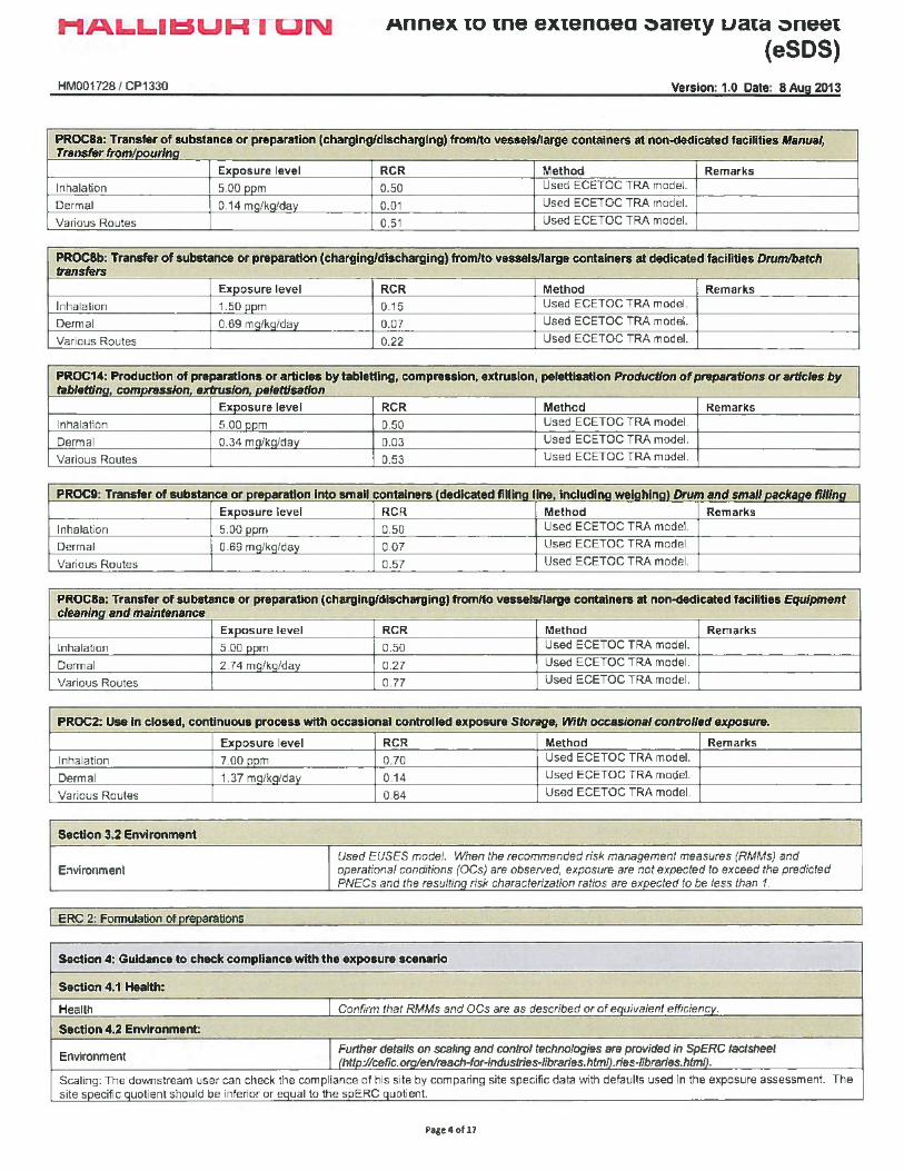
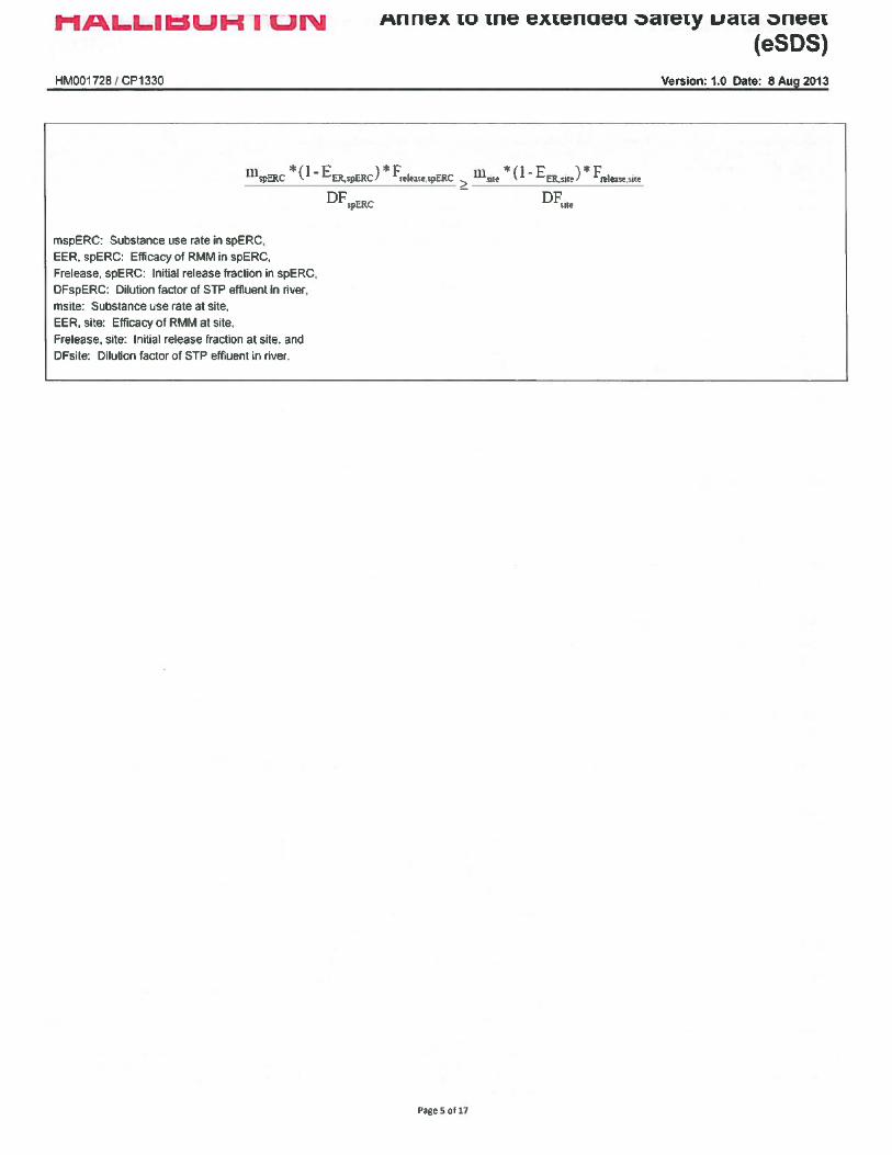
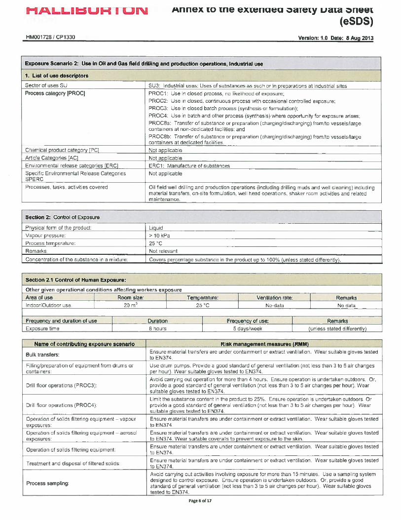
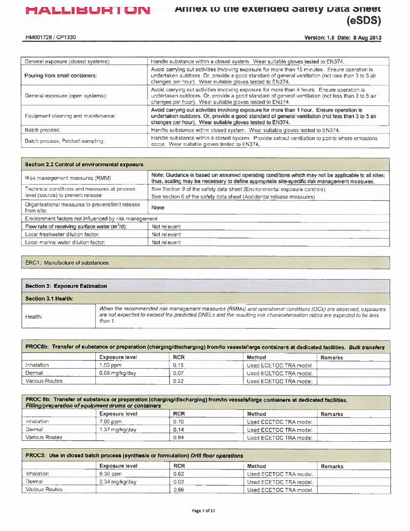
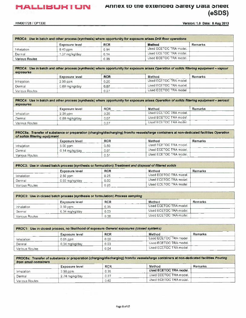
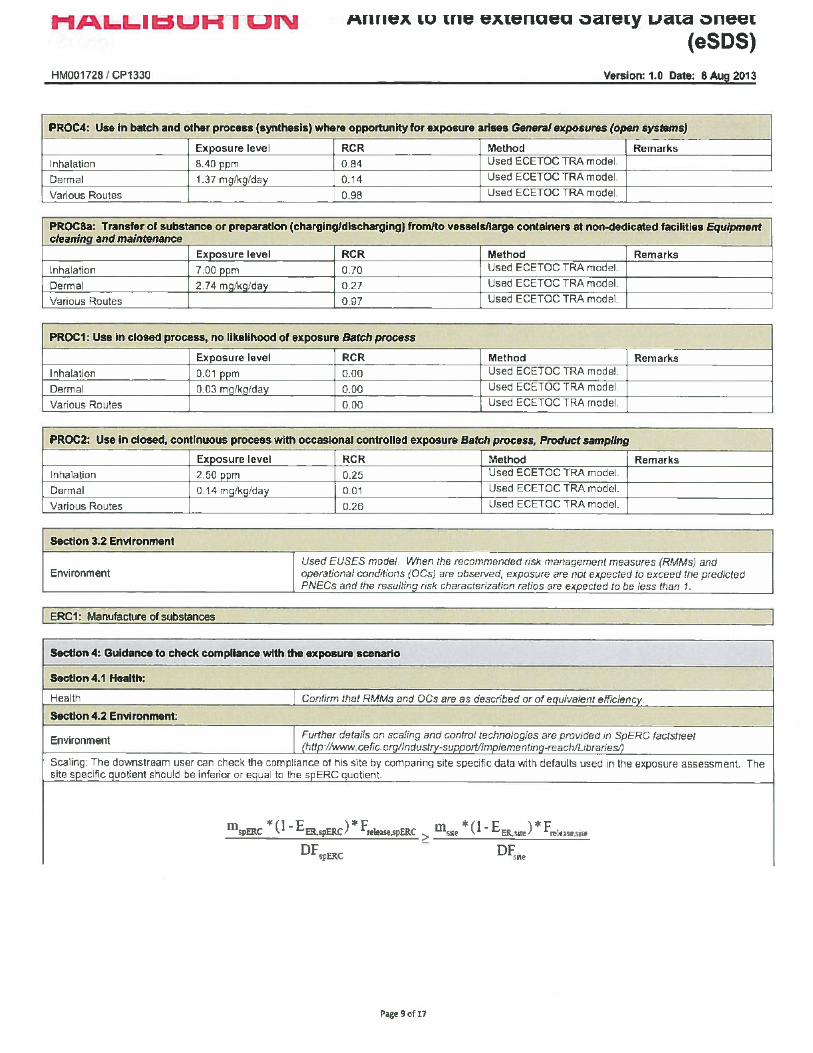
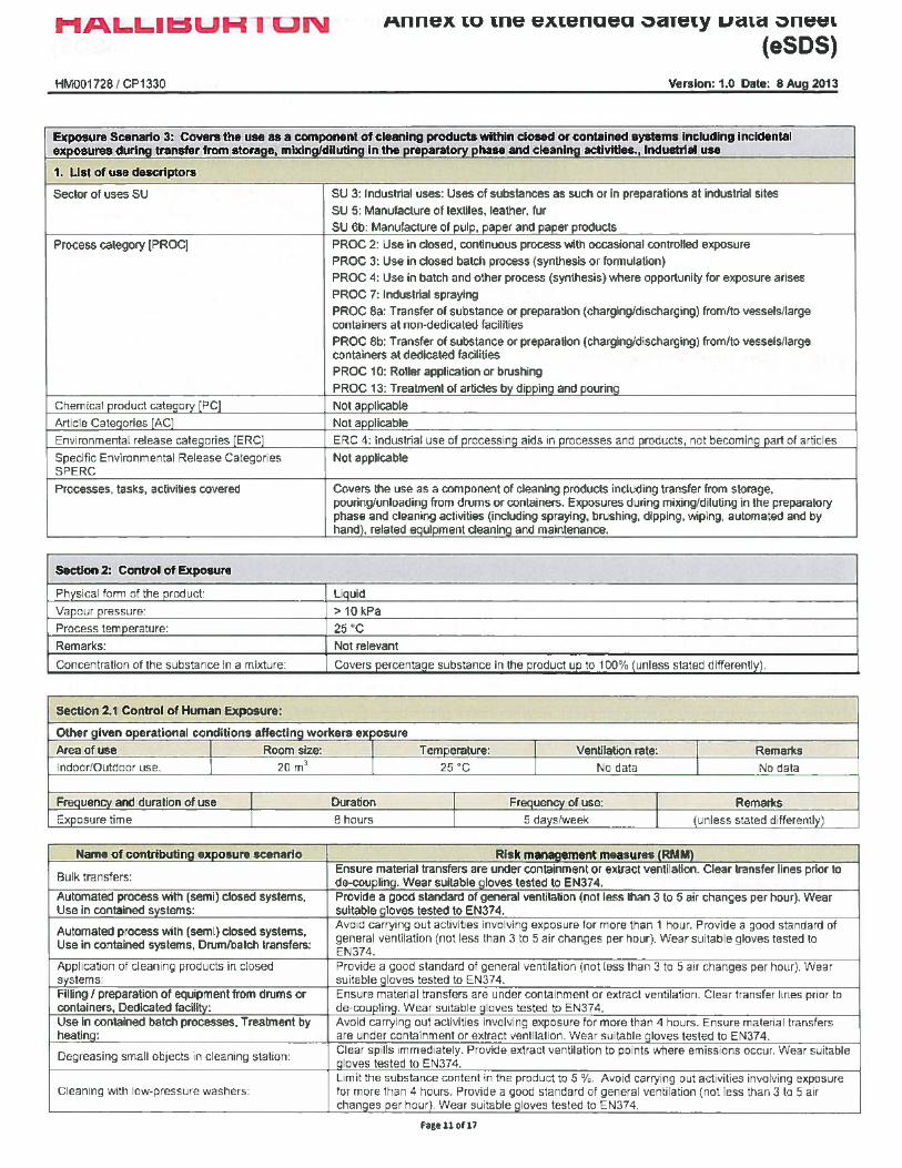
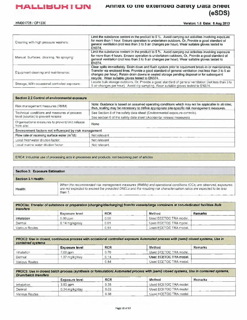
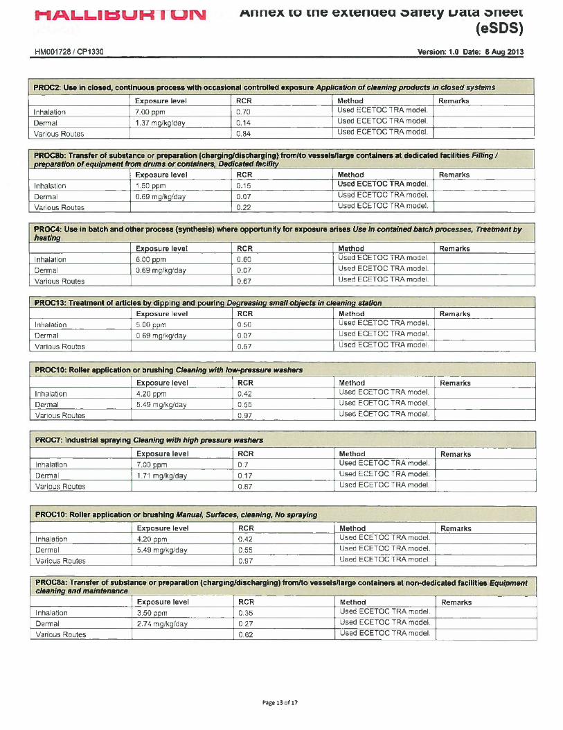
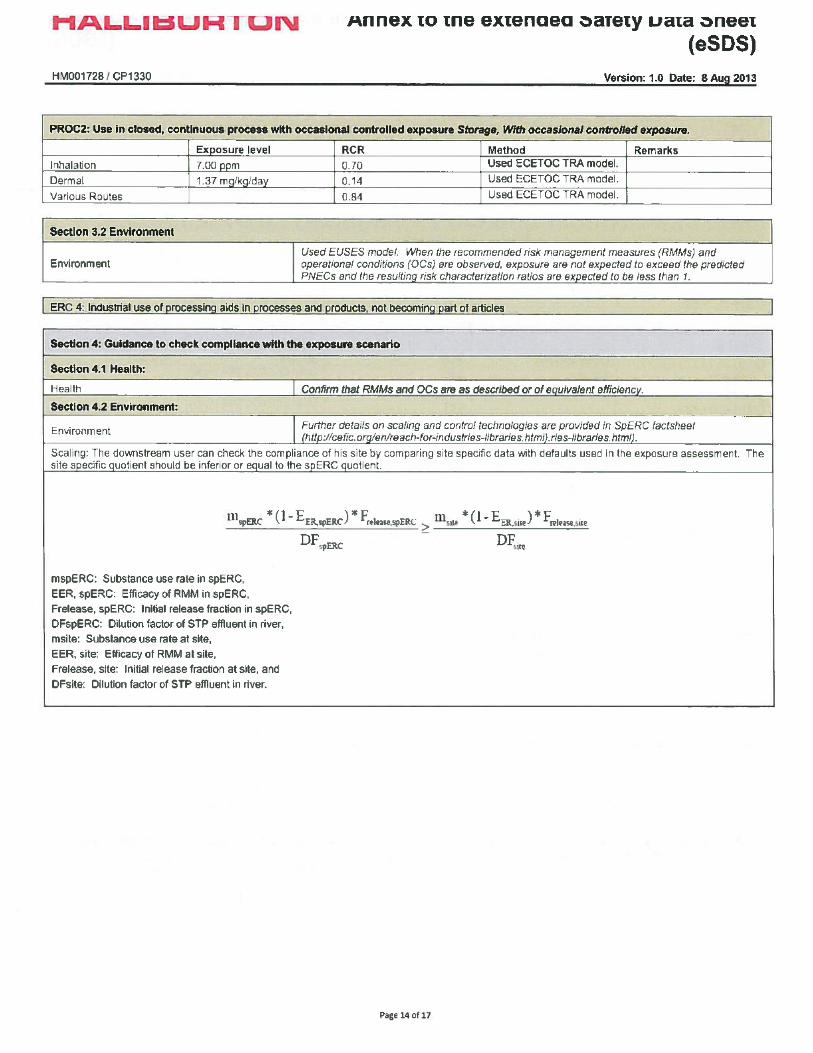
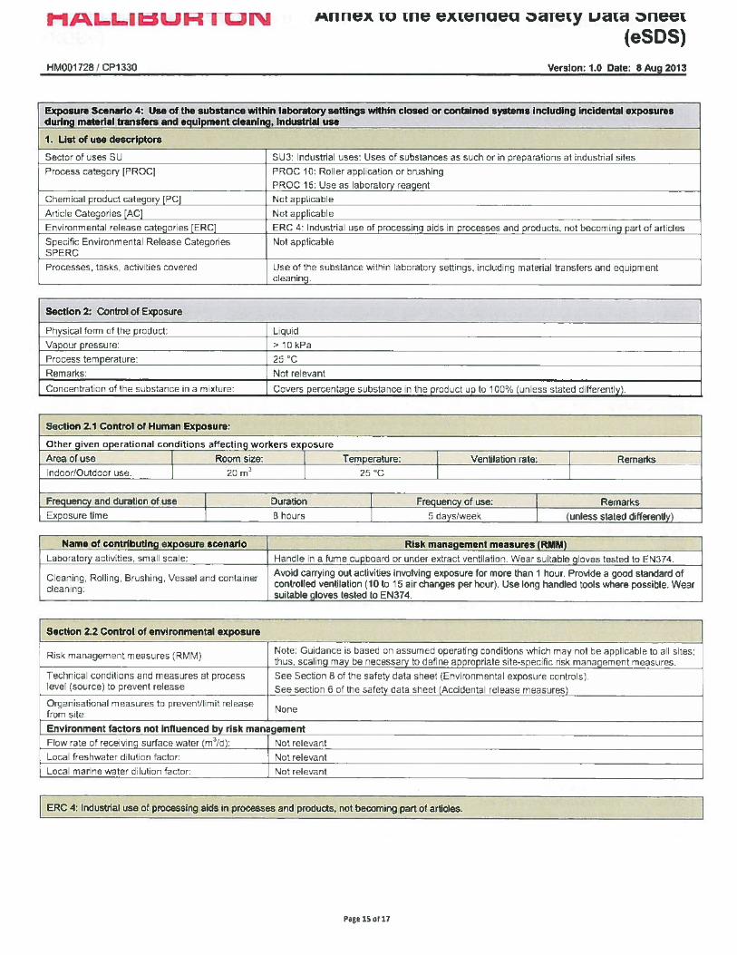
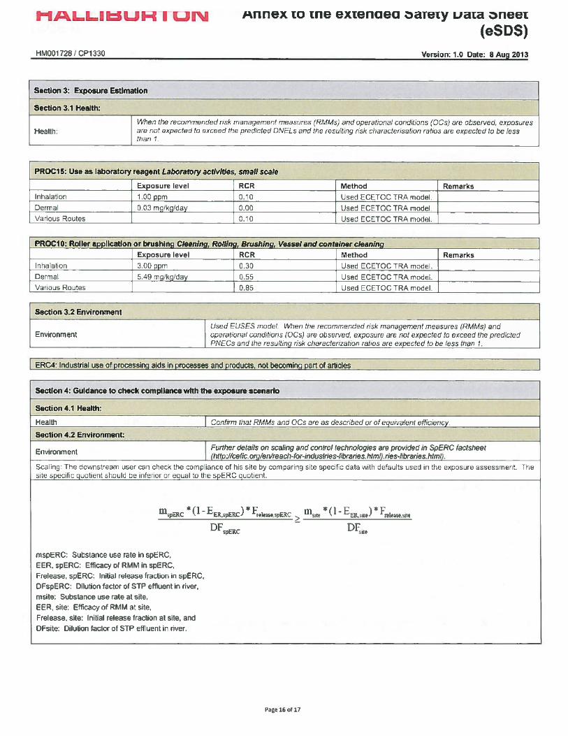
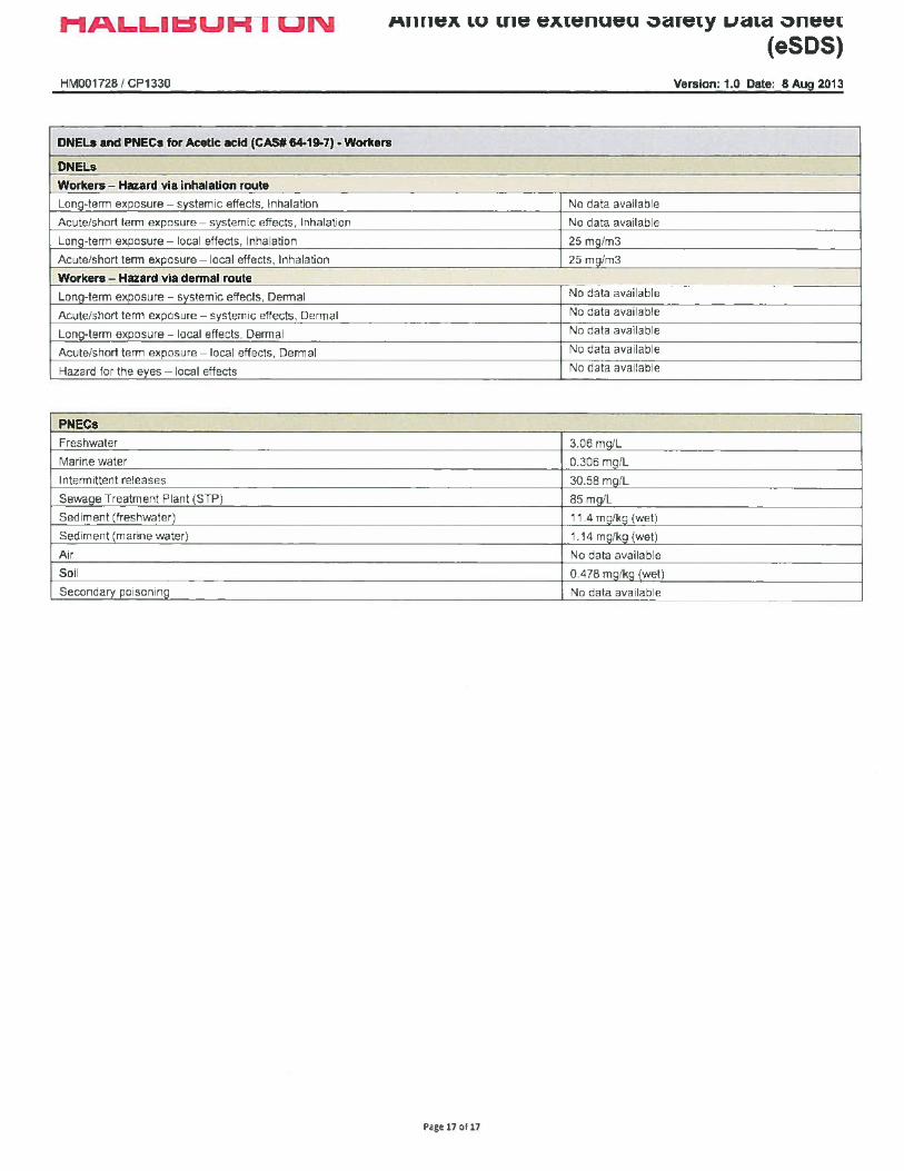

SAFETY DATA SHEETaccording to Regulation (EC) No. 453/2010
DCA-14003Revision Date: 05-Sep-2014 Revision Number: 7
Poison Control Hotline (DK): +45 82 12 12 12
DCA-14003
France ORFILA (FR): + 01 45 42 59 59
1.3. Details of the supplier of the safety data sheet
Germany Poison Center Berlin (DE): +49 030 30686 790
Recommended Use Buffer
Italy Poison Center, Milan (IT): +39 02 6610 1029
Halliburton Energy ServicesHalliburton House, Howemoss PlaceKirkhill Industrial EstateDyceAberdeen, AB21 0GNUnited Kingdom
Emergency Phone Number: +44 1224 795277 or +1 281 575 5000
www.halliburton.com
Netherlands National Poisons Information Center (NL): +31 30 274 88 88 (NB: this service is onlyavailable to health professionals)
SECTION 1: Identification of the substance/mixture and of the company/undertaking
1.1. Product Identifier
Norway Poisons Information (NO):+ 47 22 591300
For further information, please contact
Poland Poison Control and Information Centre, Warsaw (PL): +48 22 619 66 54; +48 22 619 0897
Sector of use
E-Mail address:
Spain Poison Information Service (ES): +34 91 562 04 20
SU2 - Mining, (including offshore industries)
United Kingdom NHS Direct (UK): +44 0845 46 47
1.4. Emergency telephone number
SECTION 2: Hazards Identification
+44 1224 795277 or +1 281 575 5000
Product category PC14 - Metal surface treatment products, including galvanic and electroplating products
2.1. Classification of the substance or mixture REGULATION (EC) No 1272/2008
Emergency telephone - §45 - (EC)1272/2008
Not classified
Process categories
Europe 112
PROC4 - Use in batch and other process (synthesis) where opportunity for exposurearises
1.2. Relevant identified uses of the substance or mixture and uses advised against
Croatia
_____________________________________________________________________________________________
Centar za kontrolu otrovanja (CKO): (+385 1) 23-48-342 (Poison Control Center (PCC) -Institute for Medical Research and Occupational Health)
Product Name
Page 1 / 7
Denmark
_____________________________________________________________________________________________Revision Date: 05-Sep-2014DCA-14003
Precautionary Statements - EU (§28, 1272/2008)None
2.2. Label Elements
Risk Phrases
For the full text of the R-phrases mentioned in this Section, see Section 16
None
Not classified
Contains
3.1. Substances Substance
Classification
Substances
3.2. Mixtures Not applicable
CAS Number
Not Classified
Contains no hazardous substances
SECTION 4: First aid measures
NA
4.1. Description of first aid measures Inhalation If inhaled, remove from area to fresh air. Get medical attention if respiratory
irritation develops or if breathing becomes difficult.
Signal Word
Eyes In case of contact, immediately flush eyes with plenty of water for at least 15minutes and get medical attention if irritation persists.
None
Skin Wash with soap and water. Get medical attention if irritation persists.
2.3. Other Hazards
Ingestion Under normal conditions, first aid procedures are not required.
None known
4.2. Most Important symptoms and effects, both acute and delayed
Hazard Pictograms
No significant hazards expected.
Hazard StatementsNot Classified
SECTION 3: Composition/information on Ingredients
4.3. Indication of any immediate medical attention and special treatment needed
Classification according to EU Directives 67/548/EEC or 1999/45/ECFor the full text of the R-phrases mentioned in this Section, see Section 16
Notes to Physician Treat symptomatically
Substances
SECTION 5: Firefighting Measures
EINECS CAS Number
5.1. Extinguishing media
PERCENT(w/w)
EECClassification
Suitable Extinguishing MediaAll standard fire fighting media
EU - CLP SubstanceClassification
REACH No.
Extinguishing media which must not be used for safety reasonsNone known.
Contains no hazardoussubstances
Notapplicable
NA 60 - 100% Not applicable
_____________________________________________________________________________________________
Not applicable No data available
Page 2 / 7
_____________________________________________________________________________________________Revision Date: 05-Sep-2014DCA-14003
Substances CAS Number EU UK OEL Netherlands France OEL
Avoid creating or inhaling dust.
6.3. Methods and material for containment and cleaning up
Contains no hazardoussubstances
NA Not applicable Not applicable Not applicable Not applicable
Use appropriate protective equipment. Avoid creating and breathing dust.
Hygiene MeasuresHandle in accordance with good industrial hygiene and safety practice
Scoop up and remove.
Substances CAS Number Germany MAK/TRK Spain Portugal FinlandContains no hazardoussubstances
NA Not applicable Not applicable Not applicable Not applicable
See Section 8 for additional information
7.2. Conditions for safe storage, including any incompatibilities
SECTION 6: Accidental release measures
Substances CAS Number Austria Ireland Switzerland Norway
Store away from acids. Store in a dry location.
5.2. Special hazards arising from the substance or mixture
Contains no hazardoussubstances
NA Not applicable Not applicable Not applicable Not applicable
6.4. Reference to other sections
Substances CAS Number Italy Poland Hungary Czech Republic
7.3. Specific End Use(s)
See Section 8 and 13 for additional information.
Contains no hazardoussubstances
NA Not applicable Not applicable Not applicable Not applicable
Exposure Scenario No information available
6.2. Environmental precautions
Substances CAS Number Denmark
Other Guidelines
Contains no hazardous substances NA Not applicable
No information available
5.3. Advice for firefighters
SECTION 7: Handling and Storage
None known.
SECTION 8: Exposure Controls/Personal Protection
Special Exposure HazardsNot applicable.
Derived No Effect Level (DNEL) No information available.Worker
6.1. Personal precautions, protective equipment and emergency procedures
8.1. Control parameters
7.1. Precautions for Safe Handling
_____________________________________________________________________________________________
Exposure Limits
Page 3 / 7
Special Protective Equipment for Fire-FightersNot applicable.
_____________________________________________________________________________________________Revision Date: 05-Sep-2014DCA-14003
Flash Point No data availableEvaporation rate No data availableVapor Pressure No data availableVapor Density No data availableSpecific Gravity 1.87
SECTION 9: Physical and Chemical Properties
Water Solubility Soluble in water
Respiratory Protection
Solubility in other solvents No data available
If engineering controls and work practices cannot keep exposure below occupationalexposure limits or if exposure is unknown, wear a NIOSH certified, European StandardEN 149, AS/NZS 1715:2009, or equivalent respirator when using this product. Selectionof and instruction on using all personal protective equipment, including respirators,should be performed by an Industrial Hygienist or other qualified professional.Dust/mist respirator. (N95, P2/P3)
Partition coefficient: n-octanol/water No data available
8.2. Exposure controls
9.1. Information on basic physical and chemical properties
Autoignition Temperature No data available
General Population
Decomposition Temperature No data available
Hand Protection Normal work gloves.
Viscosity No data availableExplosive Properties No information available
Engineering Controls
Oxidizing Properties No information available
Skin Protection Normal work coveralls.
A well ventilated area to control dust levels. Local exhaust ventilation should be used inareas without good cross ventilation.
9.2. Other information
Predicted No Effect Concentration (PNEC)
VOC Content (%) No data available
Eye Protection Wear safety glasses or goggles to protect against exposure.
SECTION 10: Stability and Reactivity
No information available.
Personal protective equipment
10.1. Reactivity
Property Values
Not applicable
Other Precautions
10.2. Chemical Stability
Remarks/ - Method
None known.
Stable
pH:
10.3. Possibility of Hazardous Reactions
8
Will Not Occur
Freezing Point/Range
10.4. Conditions to Avoid
No data available
None anticipated
Melting Point/Range No data available
Environmental Exposure Controls
Boiling Point/Range No data available
No information available
If engineering controls and work practices cannot prevent excessive exposures, the selection and proper use of personalprotective equipment should be determined by an industrial hygienist or other qualified professional based on the specificapplication of this product.
No information availableOdor: OdorlessPhysical State:
_____________________________________________________________________________________________
Solid Color:
Page 4 / 7
WhiteOdor Threshold:
_____________________________________________________________________________________________DCA-14003 Revision Date: 05-Sep-2014
Inhalation May cause mild respiratory irritation.
LD50 Oral: 4220 mg/kg (rat)
Eye Contact
SECTION 12: Ecological Information
Toxicology data for the components
May cause mild eye irritation.
12.1. Toxicity
Strong acids.
Ecotoxicity Effects
Substances
Substances CASNumber
Toxicity to Algae Toxicity to Fish Toxicity toMicroorganisms
Toxicity toInvertebrates
CASNumber
LD50 Oral
Contains nohazardoussubstances
NA No information available No information available No information available No information available
LD50 Dermal LC50 Inhalation
Skin Contact May cause mild skin irritation.
12.2. Persistence and degradability
Contains no hazardoussubstances
NA
The methods for determining biodegradability are not applicable to inorganic substances.
No data available No data available
Substances CAS Number Persistence and Degradability
No data available
11.1. Information on Toxicological Effects
Contains no hazardous substances NA No information available
Carbon monoxide and carbon dioxide.
12.3. Bioaccumulative potential
Ingestion
Does not bioaccumulate
None known
Substances CAS Number Log Pow
SECTION 11: Toxicological Information
Contains no hazardous substances NA No information available
Acute Toxicity
12.4. Mobility in soil No information available
10.6. Hazardous Decomposition Products
Chronic Effects/Carcinogenicity No data available to indicate product or components present at greater than 1% arechronic health hazards.
10.5. Incompatible Materials
_____________________________________________________________________________________________Page 5 / 7
_____________________________________________________________________________________________Revision Date: 05-Sep-2014DCA-14003
Not restricted
Follow all applicable national or local regulations.
Transport Hazard Class(es): Not applicablePacking Group: Not applicable
Transport Hazard Class(es): Not applicable
Environmental hazard: Not applicable
Endocrine Disruptor InformationThis product does not contain any known or suspected endocrine disruptors
Packing Group: Not applicable
IATA/ICAO UN Number: Not restricted.
Environmental Hazards: Not applicable
UN Proper Shipping Name: Not restricted
SECTION 14: Transport Information
12.5. Results of PBT and vPvB assessment
Transport Hazard Class(es): Not applicablePacking Group: Not applicable
No information available.
Environmental hazard: Not applicable
RID
13.1. Waste treatment methods
14.1. UN Number: Not restricted.
UN Number: Not restricted.
14.2. UN Proper Shipping Name: Not restricted
UN Proper Shipping Name: Not restricted
14.3. Transport Hazard Class(es): Not applicable
12.6. Other adverse effects
Transport Hazard Class(es):
14.4. Packing Group: Not applicable
Not applicable
Disposal Method
IMDG/IMO
14.5. Environmental Hazards: Not applicable
Packing Group: Not applicable
Bury in a licensed landfill according to federal, state, and local regulations.
14.6. Special Precautions for User: None
Environmental hazard: Not applicable
14.7. Transport in bulk according to Annex II of MARPOL 73/78 and the IBC Code: Not applicable
UN Number:
SECTION 15: Regulatory Information
Not restricted.
ADR
SECTION 13: Disposal Considerations
15.1. Safety, health and environmental regulations/legislation specific for the substance or mixture
Contaminated Packaging
UN Number: Not restricted.
_____________________________________________________________________________________________
UN Proper Shipping Name:
Page 6 / 7
UN Proper Shipping Name: Not restricted
_____________________________________________________________________________________________Revision Date: 05-Sep-2014DCA-14003
WGK 1: Low hazard to waters.
International Inventories
Key literature references and sources for datawww.ChemADVISOR.com/
Legend
Revision Date: 05-Sep-2014
US TSCA Inventory
Revision Note
All components listed on inventory or are exempt.
15.2. Chemical Safety Assessment
Update to Format SECTION: 8
TSCA - United States Toxic Substances Control Act Section 8(b) Inventory
No information available
This safety data sheet complies with the requirements of Regulation (EC) No. 453/2010
EINECS/ELINCS - European Inventory of Existing Commercial Chemical Substances/EU List of Notified Chemical Substances
Canadian DSL Inventory All components listed on inventory or are exempt.
Disclaimer StatementThis information is furnished without warranty, expressed or implied, as to accuracy or completeness. The information isobtained from various sources including the manufacturer and other third party sources. The information may not be validunder all conditions nor if this material is used in combination with other materials or in any process. Final determination ofsuitability of any material is the sole responsibility of the user.
SECTION 16: Other Information
DSL/NDSL - Canadian Domestic Substances List/Non-Domestic Substances List
EINECS Inventory
End of Safety Data Sheet
This product, and all its components, complies with EINECS
Full text of R-phrases referred to under Sections 2 and 3
_____________________________________________________________________________________________
None
Page 7 / 7
Germany, Water EndangeringClasses (WGK)
SAFETY DATA SHEETaccording to Regulation (EC) No. 453/2010
FRAC SANDRevision Date: 17-Feb-2014 Revision Number: 11
FRAC SAND
Germany Poison Center Berlin (DE): +49 030 30686 790
1.3 Details of the supplier of the safety data sheet
Italy Poison Center, Milan (IT): +39 02 6610 1029
Recommended Use Proppant
Netherlands National Poisons Information Center (NL): +31 30 274 88 88 (NB: this service is onlyavailable to health professionals)
Halliburton Energy ServicesHalliburton House, Howemoss PlaceKirkhill Industrial EstateDyceAberdeen, AB21 0GNUnited Kingdom
Emergency Phone Number: +44 1224 795277 or +1 281 575 5000
www.halliburton.com
Norway Poisons Information (NO):+ 47 22 591300
1. Identification of the substance/mixture and of the company/undertaking
1.1 Product Identifier
Poland Poison Control and Information Centre, Warsaw (PL): +48 22 619 66 54; +48 22 619 0897
For further information, please contact
Spain Poison Information Service (ES): +34 91 562 04 20
Sector of use
E-Mail address:
United Kingdom NHS Direct (UK): +44 0845 46 47
SU2 - Mining, (including offshore industries)
1.4 Emergency telephone number
2. Hazards Identification
+44 1224 795277 or +1 281 575 5000
Product category
2.1 Classification of the substance or mixture
PC20 - Products such as pH-regulators, flocculants, precipitants, neutralization agents,other unspecific
REGULATION (EC) No 1272/2008Carcinogenicity Category 1A - (H350)
Emergency telephone - §45 - (EC)1272/2008
Specific Target Organ Toxicity - (Repeated Exposure) Category 1 - (H372)
Process categories
Europe 112
Classification according to EU Directives 67/548/EEC or 1999/45/EC
PROC 26 - Handling of solid inorganic substances at ambient temperature
1.2 Relevant identified uses of the substance or mixture and uses advised against
Denmark Poison Control Hotline (DK): +45 82 12 12 12
Product Name
_____________________________________________________________________________________________
France
Page 1 / 8
ORFILA (FR): + 01 45 42 59 59
_____________________________________________________________________________________________FRAC SAND Revision Date: 17-Feb-2014
2.2 Label Elements
3. Composition/information on Ingredients
Hazard StatementsH350i - May cause cancer by inhalationH372 - Causes damage to organs through prolonged or repeated exposure
R49 May cause cancer by inhalation.R48/20 Harmful: danger of serious damage to health by prolonged exposurethrough inhalation.
T - Toxic.
Substances EINECS CAS Number PERCENT(w/w)
EECClassification
EU - CLP SubstanceClassification
REACH No.
Crystalline silica,quartz
238-878-4 14808-60-7 60 - 100% T; R49Xn; R48/20
Carc. 1A (H350i)STOT RE 1 (H372)
No data available
Precautionary Statements - EU (§28, 1272/2008)P201 - Obtain special instructions before useP202 - Do not handle until all safety precautions have been read and understoodP281 - Use personal protective equipment as requiredP260 - Do not breathe dust/fume/gas/mist/vapors/sprayP308 + P313 - IF exposed or concerned: Get medical advice/attentionP314 - Get medical attention/advice if you feel unwell
For the full text of the R-phrases mentioned in this Section, see Section 16
For the full text of the R-phrases mentioned in this Section, see Section 16
4. First aid measures
Contains
Hazard Pictograms
4.1 Description of first aid measures
Substances CAS Number
Inhalation If inhaled, remove from area to fresh air. Get medical attention if respiratoryirritation develops or if breathing becomes difficult.
Eyes In case of contact, immediately flush eyes with plenty of water for at least 15minutes and get medical attention if irritation persists.
Crystalline silica, quartz 14808-60-7
Skin Wash with soap and water.
Classification
Ingestion Under normal conditions, first aid procedures are not required.
Signal Word Danger
4.2 Most Important symptoms and effects, both acute and delayed
2.3 Other Hazards None known
_____________________________________________________________________________________________
Risk Phrases
Page 2 / 8

_____________________________________________________________________________________________Revision Date: 17-Feb-2014FRAC SAND
6.2 Environmental precautions
Breathing crystalline silica can cause lung disease, including silicosis and lung cancer. Crystalline silica has alsobeen associated with scleroderma and kidney disease.
5.3 Advice for firefighters
None known.
7.2 Conditions for safe storage, including any incompatibilities
5. Firefighting Measures
Store in a cool, dry location. Use good housekeeping in storage and work areas to prevent accumulation of dust. Closecontainer when not in use. Product has a shelf life of 36 months.
Special Protective Equipment for Fire-FightersNot applicable.
Notes to Physician
6.3 Methods and material for containment and cleaning up
7.3 Specific End Use(s)
Treat symptomatically
6. Accidental release measures
Exposure Scenario No information available
Collect using dustless method and hold for appropriate disposal. Consider possible toxic or fire hazards associated withcontaminating substances and use appropriate methods for collection, storage and disposal.
5.2 Special hazards arising from the substance or mixture
Other Guidelines No information available
5.1 Extinguishing media
8. Exposure Controls/Personal Protection
6.4 Reference to other sections
Special Exposure HazardsNot applicable.
See Section 8 and 13 for additional information.
8.1 Control parameters
6.1 Personal precautions, protective equipment and emergency procedures
4.3 Indication of any immediate medical attention and special treatment needed
Exposure Limits
Suitable Extinguishing MediaNone - does not burn.
Substances CAS Number EU UK OEL Netherlands France OEL
Use appropriate protective equipment. Avoid creating and breathing dust.
7. Handling and Storage
Crystalline silica, quartz 14808-60-7 Not applicable STEL: 0.3 mg/m3
TWA: 0.3 mg/m3
TWA: 0.075 mg/m3 0.1 mg/m3
Substances CAS Number Germany MAK/TRK Spain Portugal Finland
See Section 8 for additional information
7.1 Precautions for Safe Handling
_____________________________________________________________________________________________
This product contains quartz, cristobalite, and/or tridymite which may become airborne without a visible cloud. Avoid breathingdust. Avoid creating dusty conditions. Use only with adequate ventilation to keep exposure below recommended exposurelimits. Wear a NIOSH certified, European Standard En 149, or equivalent respirator when using this product. Material isslippery when wet.
Page 3 / 8
Extinguishing media which must not be used for safety reasonsNone known.
Hygiene MeasuresHandle in accordance with good industrial hygiene and safety practice
_____________________________________________________________________________________________FRAC SAND Revision Date: 17-Feb-2014
Eye Protection Wear safety glasses or goggles to protect against exposure.
Austria Ireland
Other Precautions None known.
Substances CAS Number
Environmental Exposure Controls No information available
Denmark
Switzerland Norway
Crystalline silica, quartz
9. Physical and Chemical Properties
14808-60-7 TWA: 0.3 mg/m3 TWA: 0.1 mg/m3
TWA: 0.025 mg/m3 TWA: 0.05 mg/m3
TWA: 0.2 mg/m3
9.1 Information on basic physical and chemical properties
Crystalline silica, quartz 14808-60-7 Not applicable Not applicable
Derived No Effect Level (DNEL) No information available.
Not applicable STEL: 0.9 mg/m3
STEL: 0.3 mg/m3
TWA: 0.3 mg/m3
TWA: 0.1 mg/m3
Worker
Crystalline silica, quartz 14808-60-7
Property Values Remarks/ - Method pH: No data available
General Population
Freezing Point/Range No data availableMelting Point/Range No data availableBoiling Point/Range No data available
Substances CAS Number
Flash Point No data available
Predicted No Effect Concentration (PNEC) No information available.
Evaporation rate No data available
Italy Poland
Vapor Pressure No data availableVapor Density No data available
Hungary Czech Republic
Specific Gravity 2.65
8.2 Exposure controls
0,15 mg/m3
Water Solubility Insoluble in water
VLA-ED: 0.1 mg/m3
Engineering Controls
Solubility in other solvents No data available
Use approved industrial ventilation and local exhaust as required to maintain exposuresbelow applicable exposure limits.
Crystalline silica, quartz
Partition coefficient: n-octanol/water No data available
14808-60-7
Personal protective equipment
Autoignition Temperature No data available
Not applicable
Decomposition Temperature No data available
NDS: 2 mg/m3 NDS:0.3 mg/m3 NDS: 4.0
mg/m3 NDS: 1.0mg/m3
Viscosity No data available
Respiratory Protection Wear a NIOSH certified, European Standard EN 149 (FFP2/FFP3), or equivalentrespirator when using this product.
Explosive Properties No information available
TWA: 0.15 mg/m3 Not applicable
Oxidizing Properties No information available
Hand Protection Normal work gloves.
Substances CAS Number
Skin Protection Wear clothing appropriate for the work environment. Dusty clothing should be launderedbefore reuse. Use precautionary measures to avoid creating dust when removing orlaundering clothing.
Odor Threshold: No information availableOdor: Odorless
_____________________________________________________________________________________________
Physical State: Solid
Page 4 / 8
Color: Tan
_____________________________________________________________________________________________Revision Date: 17-Feb-2014FRAC SAND
9.2 Other information
Inhalation Inhaled crystalline silica in the form of quartz or cristobalite from occupational sources iscarcinogenic to humans (IARC, Group 1). There is sufficient evidence in experimentalanimals for the carcinogenicity of tridymite (IARC, Group 2A).
Breathing silica dust may cause irritation of the nose, throat, and respiratory passages.Breathing silica dust may not cause noticeable injury or illness even though permanentlung damage may be occurring. Inhalation of dust may also have serious chronic healtheffects (See "Chronic Effects/Carcinogenicity" subsection below).
Hydrofluoric acid.
10.1 Reactivity
Eye Contact May cause mechanical irritation to eye.
10.3 Possibility of Hazardous Reactions
10.6 Hazardous Decomposition Products
Skin Contact None known.
10. Stability and Reactivity
VOC Content (%)
Ingestion None known
Amorphous silica may transform at elevated temperatures to tridymite (870 C) or cristobalite (1470 C).
Will Not Occur
Not applicable
Chronic Effects/CarcinogenicitySilicosis: Excessive inhalation of respirable crystalline silica dust may cause aprogressive, disabling, and sometimes-fatal lung disease called silicosis.Symptoms include cough, shortness of breath, wheezing, non-specific chestillness, and reduced pulmonary function. This disease is exacerbated bysmoking. Individuals with silicosis are predisposed to develop tuberculosis.
Cancer Status: The International Agency for Research on Cancer (IARC) hasdetermined that crystalline silica inhaled in the form of quartz or cristobalitefrom occupational sources can cause lung cancer in humans (Group 1 -carcinogenic to humans) and has determined that there is sufficient evidence inexperimental animals for the carcinogenicity of tridymite (Group 2A - possiblecarcinogen to humans). Refer to IARC Monograph 68, Silica, Some Silicates and Organic Fibres (June 1997) in conjunction with the use of these minerals.The National Toxicology Program classifies respirable crystalline silica as"Known to be a human carcinogen". Refer to the 9th Report on Carcinogens(2000). The American Conference of Governmental Industrial Hygienists(ACGIH) classifies crystalline silica, quartz, as a suspected human carcinogen(A2).
There is some evidence that breathing respirable crystalline silica or thedisease silicosis is associated with an increased incidence of significant diseaseendpoints such as scleroderma (an immune system disorder manifested byscarring of the lungs, skin, and other internal organs) and kidney disease.
10.4 Conditions to Avoid
11. Toxicological Information
10.2 Chemical Stability
Toxicology data for the components
None anticipated
11.1 Information on Toxicological Effects
No data available
_____________________________________________________________________________________________
10.5 Incompatible Materials
Acute Toxicity
Page 5 / 8
Stable
_____________________________________________________________________________________________Revision Date: 17-Feb-2014FRAC SAND
Contains crystalline silica which may cause silicosis, a delayed and progressive lung disease. TheIARC and NTP have determined there is sufficient evidence in humans of the carcinogenicity ofcrystalline silica with repeated respiratory exposure.
No data available
Crystalline silica, quartz 14808-60-7 Mechanical irritation of the eyes is possible.
Substances CASNumber
Reproductive Toxicity
Substances CASNumber
Crystalline silica, quartz 14808-60-7 No significant toxicity observed in animal studies at concentration requiring classification.
Substances CASNumber
STOT - single exposure
Substances CASNumber
Crystalline silica, quartz 14808-60-7 No significant toxicity observed in animal studies at concentration requiring classification.
Skin Sensitization
LD50 Oral LD50 Dermal
Crystalline silica, quartz
Substances CASNumber
STOT - repeated exposure
14808-60-7 Did not cause sensitization on laboratory animals
Crystalline silica, quartz 14808-60-7 Causes damage to organs through prolonged or repeated exposure if inhaled Lungs
Substances CASNumber
Substances CASNumber
Aspiration hazard
Skin corrosion/irritation
LC50 Inhalation
Crystalline silica, quartz 14808-60-7 Not applicable
Substances CASNumber
Respiratory Sensitization
Crystalline silica, quartz
Crystalline silica, quartz 14808-60-7 No information available
12. Ecological Information
14808-60-7 Non-irritating to the skin
12.1 Toxicity
Crystalline silica, quartz
Ecotoxicity Effects
Substances CASNumber
Substances CASNumber
Toxicity to Algae Toxicity to Fish Toxicity toMicroorganisms
Toxicity forInvertebrates
Mutagenic Effects
Crystalline silica,quartz
14808-60-7 EC50(72h): 89 mg/L(biomass)
(Scenedesmussubspicatus) (similar
substance)
LC50(96h): 508 mg/L(Danio rerio) (similar
substance)
No information available LC50(48h): 731 mg/L(Daphnia magna)
(similar substance)LC50(48h): 33.5 mg/L(Ceriodaphnia dubia)(similar substance)
Crystalline silica, quartz 14808-60-7 Not regarded as mutagenic
12.2 Persistence and degradability
14808-60-7 500 mg/kg ( Rat )
Substances Persistence and Degradability
Substances CASNumber
Substances CASNumber
Carcinogenic Effects
_____________________________________________________________________________________________
Eye damage/irritation
No data available
Page 6 / 8
Crystalline silica, quartz 14808-60-7
_____________________________________________________________________________________________FRAC SAND Revision Date: 17-Feb-2014
Transport Hazard Class(es): Not applicable
12.6 Other adverse effects
Crystalline silica, quartz
Packing Group: Not applicable
14. Transport Information
The methods for determining biodegradability are notapplicable to inorganic substances.
Environmental hazard: Not applicable
Endocrine Disruptor InformationThis product does not contain any known or suspected endocrine disruptors
ADRUN Number: Not restricted.UN Proper Shipping Name: Not restricted
IMDG/IMO
Transport Hazard Class(es): Not applicablePacking Group: Not applicable
13. Disposal Considerations
Environmental hazard: Not applicable
UN Number: Not restricted.
12.5 Results of PBT and vPvB assessment
12.3 Bioaccumulative potential
UN Proper Shipping Name:
IATA/ICAO
Not restricted
UN Number: Not restricted.UN Proper Shipping Name: Not restricted
Transport Hazard Class(es): Not applicable
Transport Hazard Class(es): Not applicable
No information available.
Packing Group: Not applicable
Packing Group:
Environmental hazard: Not applicable
Not applicable
13.1 Waste treatment methods
12.4 Mobility in soil
Special Precautions for User None
Environmental Hazards: Not applicable
Transport in bulk according to Annex II of MARPOL 73/78 and the IBC Code Not applicable
Disposal Method
15. Regulatory Information
Bury in a licensed landfill according to federal, state, and local regulations.
RID
15.1 Safety, health and environmental regulations/legislation specific for the substance or mixture
Contaminated Packaging
UN Number:
International Inventories
Not restricted.
Follow all applicable national or local regulations.
Does not bioaccumulate
UN Proper Shipping Name:
_____________________________________________________________________________________________
Not restricted
No information available
Page 7 / 8
_____________________________________________________________________________________________FRAC SAND Revision Date: 17-Feb-2014
Canadian DSL Inventory
TSCA - United States Toxic Substances Control Act Section 8(b) Inventory
Key literature references and sources for datawww.ChemADVISOR.com/
All components listed on inventory or are exempt.
EINECS Inventory
Revision Date: 17-Feb-2014
15.2 Chemical Safety Assessment
EINECS/ELINCS - European Inventory of Existing Commercial Chemical Substances/EU List of Notified Chemical Substances
Revision Note
US TSCA Inventory
No information available
Not applicable
DSL/NDSL - Canadian Domestic Substances List/Non-Domestic Substances List
This safety data sheet complies with the requirements of Regulation (EC) No. 453/2010
All components listed on inventory or are exempt.
16. Other Information
Disclaimer StatementThis information is furnished without warranty, expressed or implied, as to accuracy or completeness. The information isobtained from various sources including the manufacturer and other third party sources. The information may not be validunder all conditions nor if this material is used in combination with other materials or in any process. Final determination ofsuitability of any material is the sole responsibility of the user.
This product, and all its components, complies with EINECS
Legend
End of Safety Data Sheet
Full text of R-phrases referred to under Sections 2 and 3
Germany, Water EndangeringClasses (WGK)
WGK 0: Generally not water endangering.
R49 May cause cancer by inhalation.R48/20 Harmful: danger of serious damage to health by prolonged exposure through inhalation.
_____________________________________________________________________________________________
All of the components in the product are on the following Inventory lists: All of the components in the product are on thefollowing Inventory lists:.
Page 8 / 8
SAFETY DATA SHEET
CARBONRT ECONO
Preparation Date: 13 August 2014 Page 1 of 11
A Safety Data Sheet is not legally required for this product under the OSHA Hazard Communication Standard (29 CFR 1910.1200). The following information is provided as a courtesy service to our customers.
SECTION 1: IDENTIFICATION OF THE SUBSTANCE / MIXTURE AND OF THE COMPANY / UNDERTAKING
1.1 Product identifier Trade name: CARBONRT® ECONO Registration number: NA Synonym(s): Ceramic Proppant; Semi-Crystalline Alumina Silicate; Sintered Kaolinite
Preparation/Revision date: 13 August 2014
1.2 Relevant identified uses of the substance or mixture and uses advised against Identified uses: Proppant for oil and natural gas well hydraulic fracturing
Uses advised against: None known
1.3 Details of the supplier of the safety data sheet Manufacturer / Supplier
Company name: CARBO Ceramics Inc.
Address: 575 N. Dairy Ashford Road, Suite 300
Houston, Texas 77079, USA
Customer service: 1-337-367-6151
1.4 Emergency telephone number For Chemical Emergency Spill, Leak, Fire, Exposure, or Accident Call CHEMTREC Day or Night Within USA and Canada: 1-800-424-9300
SECTION 2: HAZARDS IDENTIFICATION
2.1 Classification of the substance or mixture The article has been assessed and /or tested for its physical, health and environmental hazards and the following classifications apply. Classification according to the OSHA Hazard Communication Standard (29 CFR 1910.1200) Classification: Not classified
CARBO to complete
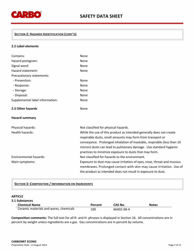
SAFETY DATA SHEET
CARBONRT ECONO
Preparation Date: 13 August 2014 Page 2 of 11
SECTION 2: HAZARDS IDENTIFICATION (CONT’D)
2.2 Label elements
Contains: None
Hazard pictogram: None
Signal word: None
Hazard statement: None
Precautionary statements:
- Prevention: None
- Response: None
- Storage: None
- Disposal: None
Supplemental label information: None 2.3 Other hazards None
Hazard summary
Physical hazards: Not classified for physical hazards.
Health hazards: While the use of this product as intended generally does not create
respirable dusts, small amounts may form from transport or
conveyance. Prolonged inhalation of insoluble, respirable (less than 10
micron) dusts can lead to pulmonary damage. Use standard hygienic
practices to minimize exposure to dusts that may form.
Environmental hazards: Not classified for hazards to the environment.
Main symptoms: Exposure to dust may cause irritation of eyes, nose, throat and mucous
membranes. Prolonged contact with skin may cause irritation. Use of
the product as intended does not result in exposure to dust.
SECTION 3: COMPOSITION / INFORMATION ON INGREDIENTS
ARTICLE 3.1 Substances
Chemical Name Percent CAS No. Notes Ceramic materials and wares, chemicals 100 66402-68-4
-
Composition comments: The full text for all R- and H- phrases is displayed in Section 16. All concentrations are in percent by weight unless ingredients are a gas. Gas concentrations are in percent by volume.
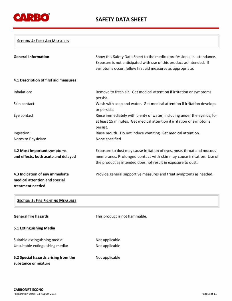
SAFETY DATA SHEET
CARBONRT ECONO
Preparation Date: 13 August 2014 Page 3 of 11
SECTION 4: FIRST AID MEASURES
General Information Show this Safety Data Sheet to the medical professional in attendance.
Exposure is not anticipated with use of this product as intended. If
symptoms occur, follow first aid measures as appropriate.
4.1 Description of first aid measures
Inhalation: Remove to fresh air. Get medical attention if irritation or symptoms
persist.
Skin contact: Wash with soap and water. Get medical attention if irritation develops
or persists.
Eye contact: Rinse immediately with plenty of water, including under the eyelids, for
at least 15 minutes. Get medical attention if irritation or symptoms
persist.
Ingestion: Rinse mouth. Do not induce vomiting. Get medical attention.
Notes to Physician: None specified
4.2 Most important symptoms Exposure to dust may cause irritation of eyes, nose, throat and mucous
and effects, both acute and delayed membranes. Prolonged contact with skin may cause irritation. Use of
the product as intended does not result in exposure to dust.
4.3 Indication of any immediate Provide general supportive measures and treat symptoms as needed.
medical attention and special
treatment needed
SECTION 5: FIRE FIGHTING MEASURES
General fire hazards This product is not flammable.
5.1 Extinguishing Media
Suitable extinguishing media: Not applicable
Unsuitable extinguishing media: Not applicable
5.2 Special hazards arising from the Not applicable
substance or mixture
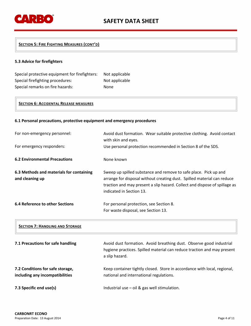
SAFETY DATA SHEET
CARBONRT ECONO
Preparation Date: 13 August 2014 Page 4 of 11
SECTION 5: FIRE FIGHTING MEASURES (CONT’D)
5.3 Advice for firefighters
Special protective equipment for firefighters: Not applicable
Special firefighting procedures: Not applicable
Special remarks on fire hazards: None
SECTION 6: ACCIDENTAL RELEASE MEASURES
6.1 Personal precautions, protective equipment and emergency procedures
For non-emergency personnel: Avoid dust formation. Wear suitable protective clothing. Avoid contact
with skin and eyes.
For emergency responders: Use personal protection recommended in Section 8 of the SDS.
6.2 Environmental Precautions None known
6.3 Methods and materials for containing Sweep up spilled substance and remove to safe place. Pick up and
and cleaning up arrange for disposal without creating dust. Spilled material can reduce
traction and may present a slip hazard. Collect and dispose of spillage as
indicated in Section 13.
6.4 Reference to other Sections For personal protection, see Section 8.
For waste disposal, see Section 13.
SECTION 7: HANDLING AND STORAGE
7.1 Precautions for safe handling Avoid dust formation. Avoid breathing dust. Observe good industrial
hygiene practices. Spilled material can reduce traction and may present
a slip hazard.
7.2 Conditions for safe storage, Keep container tightly closed. Store in accordance with local, regional,
including any incompatibilities national and international regulations.
7.3 Specific end use(s) Industrial use – oil & gas well stimulation.
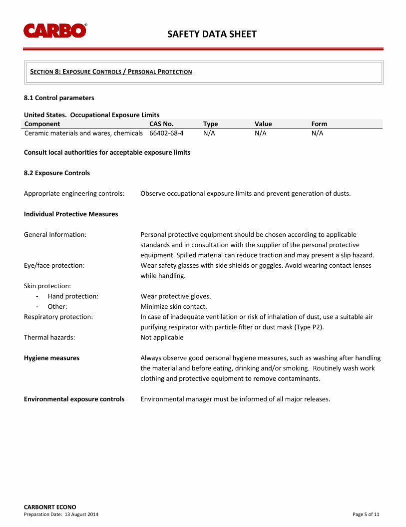
SAFETY DATA SHEET
CARBONRT ECONO
Preparation Date: 13 August 2014 Page 5 of 11
SECTION 8: EXPOSURE CONTROLS / PERSONAL PROTECTION
8.1 Control parameters United States. Occupational Exposure Limits Component CAS No. Type Value Form
Ceramic materials and wares, chemicals 66402-68-4 N/A N/A N/A
Consult local authorities for acceptable exposure limits
8.2 Exposure Controls
Appropriate engineering controls: Observe occupational exposure limits and prevent generation of dusts.
Individual Protective Measures
General Information: Personal protective equipment should be chosen according to applicable
standards and in consultation with the supplier of the personal protective
equipment. Spilled material can reduce traction and may present a slip hazard.
Eye/face protection: Wear safety glasses with side shields or goggles. Avoid wearing contact lenses
while handling.
Skin protection:
- Hand protection: Wear protective gloves.
- Other: Minimize skin contact.
Respiratory protection: In case of inadequate ventilation or risk of inhalation of dust, use a suitable air
purifying respirator with particle filter or dust mask (Type P2).
Thermal hazards: Not applicable
Hygiene measures Always observe good personal hygiene measures, such as washing after handling
the material and before eating, drinking and/or smoking. Routinely wash work
clothing and protective equipment to remove contaminants.
Environmental exposure controls Environmental manager must be informed of all major releases.
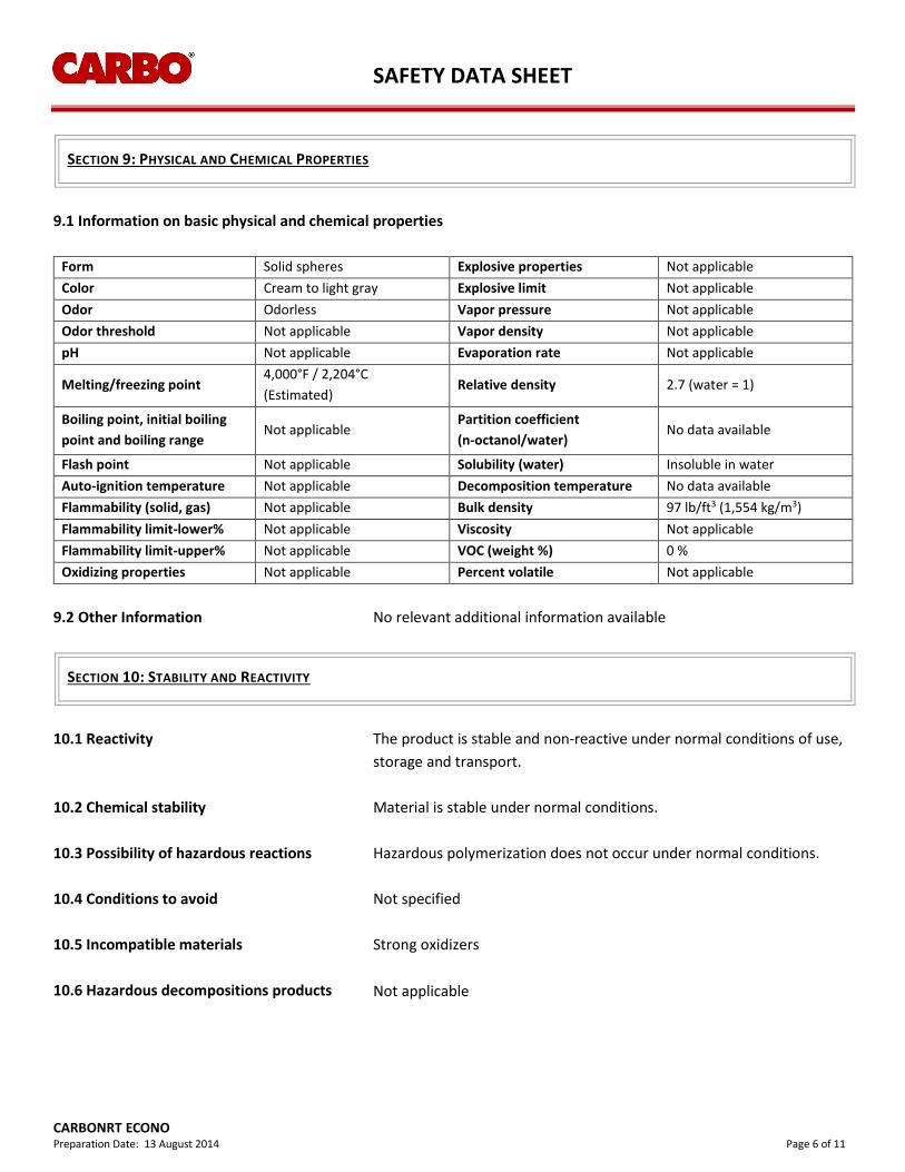
SAFETY DATA SHEET
CARBONRT ECONO
Preparation Date: 13 August 2014 Page 6 of 11
SECTION 9: PHYSICAL AND CHEMICAL PROPERTIES
9.1 Information on basic physical and chemical properties
Form Solid spheres Explosive properties Not applicable
Color Cream to light gray Explosive limit Not applicable
Odor Odorless Vapor pressure Not applicable
Odor threshold Not applicable Vapor density Not applicable
pH Not applicable Evaporation rate Not applicable
Melting/freezing point 4,000°F / 2,204°C
(Estimated) Relative density 2.7 (water = 1)
Boiling point, initial boiling
point and boiling range Not applicable
Partition coefficient
(n-octanol/water) No data available
Flash point Not applicable Solubility (water) Insoluble in water
Auto-ignition temperature Not applicable Decomposition temperature No data available
Flammability (solid, gas) Not applicable Bulk density 97 lb/ft3 (1,554 kg/m3)
Flammability limit-lower% Not applicable Viscosity Not applicable
Flammability limit-upper% Not applicable VOC (weight %) 0 %
Oxidizing properties Not applicable Percent volatile Not applicable
9.2 Other Information No relevant additional information available
SECTION 10: STABILITY AND REACTIVITY
10.1 Reactivity The product is stable and non-reactive under normal conditions of use,
storage and transport.
10.2 Chemical stability Material is stable under normal conditions.
10.3 Possibility of hazardous reactions Hazardous polymerization does not occur under normal conditions.
10.4 Conditions to avoid Not specified
10.5 Incompatible materials Strong oxidizers
10.6 Hazardous decompositions products Not applicable
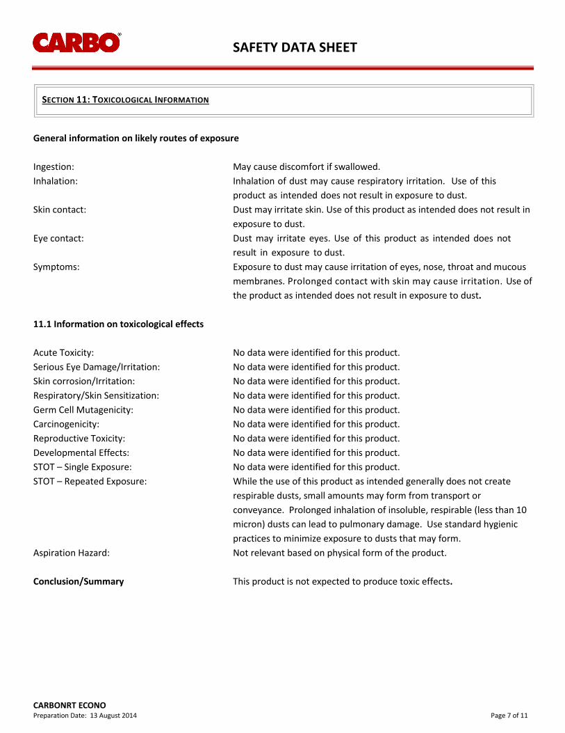
SAFETY DATA SHEET
CARBONRT ECONO
Preparation Date: 13 August 2014 Page 7 of 11
SECTION 11: TOXICOLOGICAL INFORMATION
General information on likely routes of exposure
Ingestion: May cause discomfort if swallowed.
Inhalation: Inhalation of dust may cause respiratory irritation. Use of this
product as intended does not result in exposure to dust.
Skin contact: Dust may irritate skin. Use of this product as intended does not result in
exposure to dust.
Eye contact: Dust may irritate eyes. Use of this product as intended does not
result in exposure to dust.
Symptoms: Exposure to dust may cause irritation of eyes, nose, throat and mucous
membranes. Prolonged contact with skin may cause irritation. Use of
the product as intended does not result in exposure to dust.
11.1 Information on toxicological effects
Acute Toxicity: No data were identified for this product.
Serious Eye Damage/Irritation: No data were identified for this product.
Skin corrosion/Irritation: No data were identified for this product.
Respiratory/Skin Sensitization: No data were identified for this product.
Germ Cell Mutagenicity: No data were identified for this product.
Carcinogenicity: No data were identified for this product.
Reproductive Toxicity: No data were identified for this product.
Developmental Effects: No data were identified for this product.
STOT – Single Exposure: No data were identified for this product.
STOT – Repeated Exposure: While the use of this product as intended generally does not create
respirable dusts, small amounts may form from transport or
conveyance. Prolonged inhalation of insoluble, respirable (less than 10
micron) dusts can lead to pulmonary damage. Use standard hygienic
practices to minimize exposure to dusts that may form.
Aspiration Hazard: Not relevant based on physical form of the product.
Conclusion/Summary This product is not expected to produce toxic effects.
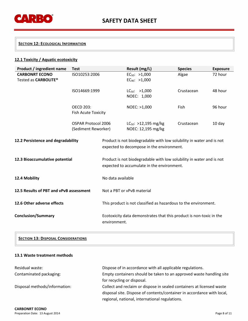
SAFETY DATA SHEET
CARBONRT ECONO
Preparation Date: 13 August 2014 Page 8 of 11
SECTION 12: ECOLOGICAL INFORMATION
12.1 Toxicity / Aquatic ecotoxicity
Product / ingredient name Test Result (mg/L) Species Exposure
CARBONRT ECONO Tested as CARBOLITE®
ISO10253:2006
EC50: >1,000 EC90: >1,000
Algae 72 hour
ISO14669:1999
LC50: >1,000 NOEC: 1,000
Crustacean 48 hour
OECD 203: Fish Acute Toxicity
NOEC: >1,000
Fish 96 hour
OSPAR Protocol 2006 (Sediment Reworker)
LC50: >12,195 mg/kg NOEC: 12,195 mg/kg
Crustacean 10 day
12.2 Persistence and degradability Product is not biodegradable with low solubility in water and is not
expected to decompose in the environment.
12.3 Bioaccumulative potential Product is not biodegradable with low solubility in water and is not
expected to accumulate in the environment.
12.4 Mobility No data available
12.5 Results of PBT and vPvB assessment Not a PBT or vPvB material
12.6 Other adverse effects This product is not classified as hazardous to the environment.
Conclusion/Summary Ecotoxicity data demonstrates that this product is non-toxic in the
environment.
SECTION 13: DISPOSAL CONSIDERATIONS
13.1 Waste treatment methods
Residual waste: Dispose of in accordance with all applicable regulations.
Contaminated packaging: Empty containers should be taken to an approved waste handling site
for recycling or disposal.
Disposal methods/information: Collect and reclaim or dispose in sealed containers at licensed waste
disposal site. Dispose of contents/container in accordance with local,
regional, national, international regulations.
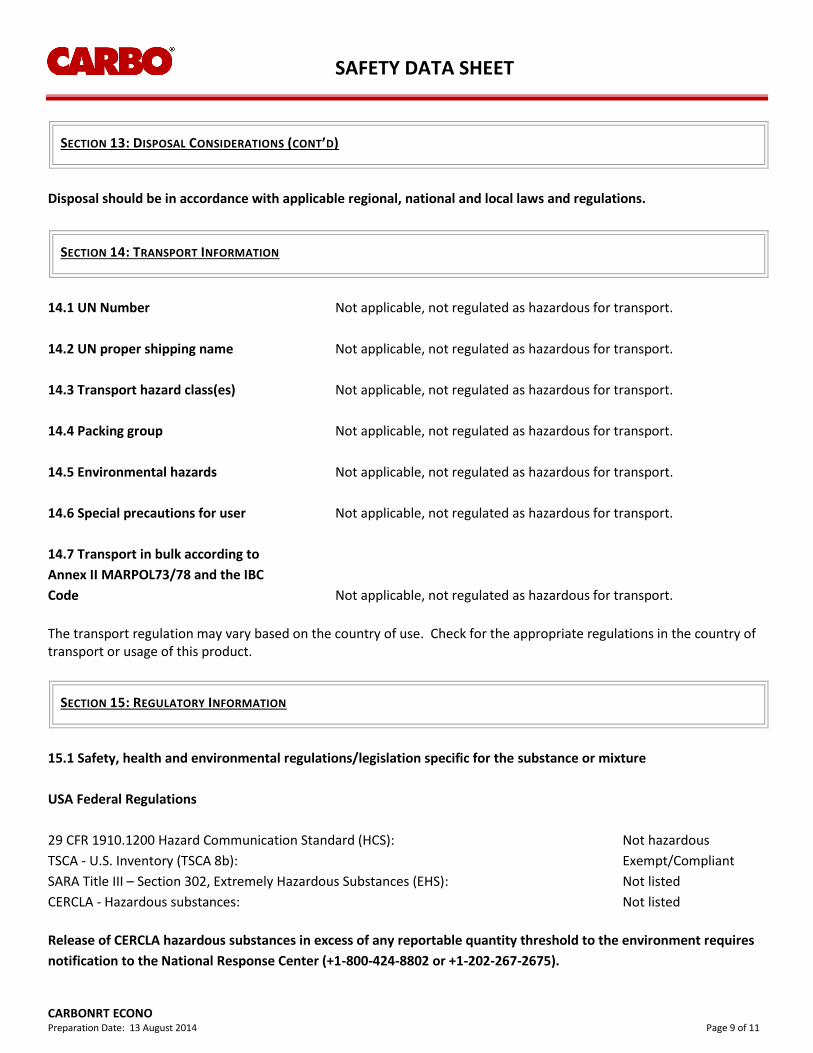
SAFETY DATA SHEET
CARBONRT ECONO
Preparation Date: 13 August 2014 Page 9 of 11
SECTION 13: DISPOSAL CONSIDERATIONS (CONT’D)
Disposal should be in accordance with applicable regional, national and local laws and regulations.
SECTION 14: TRANSPORT INFORMATION
14.1 UN Number Not applicable, not regulated as hazardous for transport.
14.2 UN proper shipping name Not applicable, not regulated as hazardous for transport.
14.3 Transport hazard class(es) Not applicable, not regulated as hazardous for transport.
14.4 Packing group Not applicable, not regulated as hazardous for transport.
14.5 Environmental hazards Not applicable, not regulated as hazardous for transport.
14.6 Special precautions for user Not applicable, not regulated as hazardous for transport.
14.7 Transport in bulk according to
Annex ӀӀ MARPOL73/78 and the IBC
Code Not applicable, not regulated as hazardous for transport.
The transport regulation may vary based on the country of use. Check for the appropriate regulations in the country of transport or usage of this product.
SECTION 15: REGULATORY INFORMATION
15.1 Safety, health and environmental regulations/legislation specific for the substance or mixture
USA Federal Regulations
29 CFR 1910.1200 Hazard Communication Standard (HCS): Not hazardous
TSCA - U.S. Inventory (TSCA 8b): Exempt/Compliant
SARA Title III – Section 302, Extremely Hazardous Substances (EHS): Not listed
CERCLA - Hazardous substances: Not listed
Release of CERCLA hazardous substances in excess of any reportable quantity threshold to the environment requires
notification to the National Response Center (+1-800-424-8802 or +1-202-267-2675).

SAFETY DATA SHEET
CARBONRT ECONO
Preparation Date: 13 August 2014 Page 10 of 11
SECTION 15: REGULATORY INFORMATION (CONT’D)
SARA Title III – 311/312, Hazard Classes:
Fire / Flammability No
Reactivity No
Release of Pressure No
Acute Health Hazard No
Chronic Health Hazard No
SARA 313 – Toxic Chemicals: Not listed
USA State Regulations To the best of our knowledge, this product does not contain
chemicals at levels which require reporting under any State
Regulations.
Other Regulations None specified
SECTION 16: OTHER INFORMATION
Label Requirements None
List of abbreviations
CAS Chemical Abstract Service
EC50/90 Effective Concentration (median / 90th percentile)
LC50/90 Lethal Concentration (median / 90th percentile)
NOEC No Observed Effect Concentration
OSHA Occupational Safety and Health Administration (United States)
PBT Persistent, Bioaccumulative and Toxic
vPvB Very Persistent and Very Bioaccumulative
References ChemAdvisor List of Lists (LOLI)
IARC Monographs. Overall Evaluation of Carcinogenicity
IUCLID DATA Set
Information on evaluation method leading The classification for health and environmental hazards is derived by a
to the classification of mixture combination of calculation methods and test data, if available. For
details refer to Sections 9, 11 and 12.

SAFETY DATA SHEET
CARBONRT ECONO
Preparation Date: 13 August 2014 Page 11 of 11
SECTION 16: OTHER INFORMATION (CONT’D)
Training information Follow training instructions when handling this material.
SDS Revisions SDS prepared on 13 August 2014.
Disclaimer The information in the sheet was written based on the best knowledge
and experience currently available.
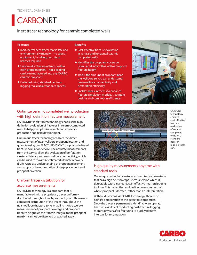
Inert tracer technology for ceramic completed wells
TECHNICAL DATA SHEET
Features
• Inert, permanent tracer that is safe and environmentally friendly—no special equipment, handling, permits or licenses required
• Uniform distribution of tracer within each proppant grain—not a coating—can be manufactured into any CARBO ceramic proppant
• Detected using standard neutron logging tools run at standard speeds
Benefits
• Cost-effective fracture evaluation in vertical and horizontal ceramic completed wells
• Identifies the proppant coverage (stimulated interval) as well as propped fracture height
• Tracks the amount of proppant near the wellbore so you can understand near-wellbore connectivity and perforation efficiency
• Enables measurements to enhance fracture simulation models, treatment designs and completion efficiency
Optimize ceramic completed well production with high definition fracture measurementCARBONRT® inert tracer technology enables the high definition evaluation of fractures in ceramic completed wells to help you optimize completion efficiency, production and field development.
Our unique tracer technology enables the direct measurement of near-wellbore proppant location and quantity using our FRACTUREVISION™ proppant-delivered fracture evaluation service. The accurate measurements from the service allow the evaluation of perforation cluster efficiency and near-wellbore connectivity, which can be used to maximize estimated ultimate recovery (EUR). A precise understanding of proppant placement also supports the optimization of stage placement and proppant diversion.
Uniform tracer distribution for accurate measurementsCARBONRT technology is a proppant that is manufactured with a proprietary tracer uniformly distributed throughout each proppant grain. This assures consistent distribution of the tracer throughout the near-wellbore fracture zone, enabling more accurate measurement of proppant coverage and propped fracture height. As the tracer is integral to the proppant matrix it cannot be dissolved or washed away.
Far detector Near detector Neutron pulsar
High quality measurements anytime with standard toolsOur unique technology features an inert traceable material that has a high neutron capture cross section which is detectable with a standard, cost-effective neutron logging tool run. This makes the result a direct measurement of where proppant is located, rather than an interpretation.
With field-proven CARBONRT technology, there is no half-life deterioration of the detectable properties. Since the tracer is permanently identifiable, an operator has the flexibility of conducting post-fracture logging months or years after fracturing to quickly identify intervals for restimulation.
CARBONRT technology enables cost-effective fracture evaluation of ceramic completed wells on a standard neutron logging tools run.
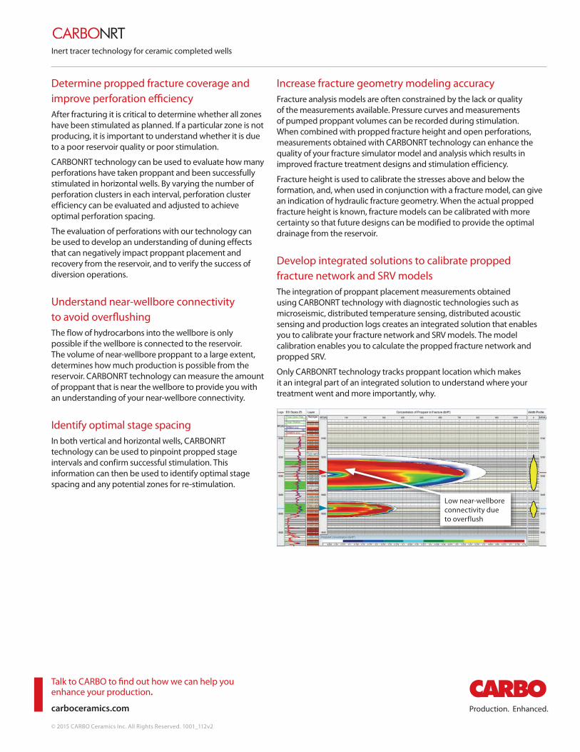
Inert tracer technology for ceramic completed wells
Talk to CARBO to find out how we can help you enhance your production.
carboceramics.com
© 2015 CARBO Ceramics Inc. All Rights Reserved. 1001_112v2
Determine propped fracture coverage and improve perforation efficiency After fracturing it is critical to determine whether all zones have been stimulated as planned. If a particular zone is not producing, it is important to understand whether it is due to a poor reservoir quality or poor stimulation.
CARBONRT technology can be used to evaluate how many perforations have taken proppant and been successfully stimulated in horizontal wells. By varying the number of perforation clusters in each interval, perforation cluster efficiency can be evaluated and adjusted to achieve optimal perforation spacing.
The evaluation of perforations with our technology can be used to develop an understanding of duning effects that can negatively impact proppant placement and recovery from the reservoir, and to verify the success of diversion operations.
Understand near-wellbore connectivity to avoid overflushingThe flow of hydrocarbons into the wellbore is only possible if the wellbore is connected to the reservoir. The volume of near-wellbore proppant to a large extent, determines how much production is possible from the reservoir. CARBONRT technology can measure the amount of proppant that is near the wellbore to provide you with an understanding of your near-wellbore connectivity.
Identify optimal stage spacingIn both vertical and horizontal wells, CARBONRT technology can be used to pinpoint propped stage intervals and confirm successful stimulation. This information can then be used to identify optimal stage spacing and any potential zones for re-stimulation.
Increase fracture geometry modeling accuracyFracture analysis models are often constrained by the lack or quality of the measurements available. Pressure curves and measurements of pumped proppant volumes can be recorded during stimulation. When combined with propped fracture height and open perforations, measurements obtained with CARBONRT technology can enhance the quality of your fracture simulator model and analysis which results in improved fracture treatment designs and stimulation efficiency.
Fracture height is used to calibrate the stresses above and below the formation, and, when used in conjunction with a fracture model, can give an indication of hydraulic fracture geometry. When the actual propped fracture height is known, fracture models can be calibrated with more certainty so that future designs can be modified to provide the optimal drainage from the reservoir.
Develop integrated solutions to calibrate propped fracture network and SRV modelsThe integration of proppant placement measurements obtained using CARBONRT technology with diagnostic technologies such as microseismic, distributed temperature sensing, distributed acoustic sensing and production logs creates an integrated solution that enables you to calibrate your fracture network and SRV models. The model calibration enables you to calculate the propped fracture network and propped SRV.
Only CARBONRT technology tracks proppant location which makes it an integral part of an integrated solution to understand where your treatment went and more importantly, why.
Low near-wellbore connectivity due to overflush
1
August 23, 2013 To: Selected Recipients From: CARBO Ceramics Inc. – Health, Safety & Environment Subject: Gadolinium Oxide – Gd2O3 (CAS 12064-62-9) Toxicological and Ecotoxicological Profile and Analysis of Use in Ceramic Proppants Summary This document provides a summary of toxicological and ecotoxicology properties about gadolinium oxide and its use as a low-level additive to ceramic proppants for non-radioactive tracer applications. • Overall, gadolinium oxide has a low order of toxicity to human health and
the environment; it is not classified as a hazardous material by industry or government agencies and in fact has commercial applications as a constituent in intravenous medical products.
• Gadolinium oxide will not be bioavailable in the finished ceramic proppant
particles when they are placed on the market and used in fracturing applications. Proppants containing gadolinium oxide should not be viewed as a toxicological concern.
Background: Gadolinium oxide is one of the most commonly available forms of gadolinium, a rare earth metal that is a member of the lanthanide group of chemical elements. It is currently being marketed for use as a non-radioactive tracer for proppants within the offshore oil and gas industry. Gadolinium and gadolinium compounds are also used in:
(1) contrasting agents for Magnetic Resonance Imaging (MRI); (2) drainage basin erosion tracers; (3) glass, optic and ceramic applications; (4) advanced electronics; (5) lightweight structural components in aerospace; (6) electrochemical applications such as fuel cells; (7) control rods in nuclear power plants; and (8) production of phosphors for use in lighting and television applications.
2
Toxicological Hazards: Rare earth metals have long been evaluated for pharmacological and toxicological effects. Toxicity varies by the form of the metal (as nitrates, chlorides, oxides, chloride–citrate complexes, etc.). Early studies were confounded by poor separation and purification procedures that yielded impure lanthanides. Therefore, only the most recent, high-quality, and relevant publically available data were considered in developing this summary. The following summary of toxicological and ecotoxicological properties are related to the particulate form of this material. There are no published data and no known adverse effects associated with exposure to the bulk/massive form. Human Health Acute Toxicity The acute toxic response of rare earth metal compounds in the powder form has been determined in laboratory animals for the lanthanides by intraperitoneal (IP), intravenous (IV), and oral routes. Because the IP and IV routes are not relevant for occupational and environmental release scenarios, only data from the oral route have been considered. Gadolinium oxide powder is considered to have low potential for toxic effects in humans, based on a reported acute oral LD50 of greater than 5,000 mg/kg in rats and a study that reported all the oxides of the lanthanides were tolerated by female rats at the highest dose tested, 1000 mg/kg. This may be related to the protein-binding properties of polyvalent metals such as gadolinium, which reduces absorption of the substance in the stomach. Further supporting this conclusion, gadolinium and gadolinium oxide were notified under the European Union (EU) Registration, Evaluation and Authorization of Chemicals (REACH) as non-hazardous for acute endpoints by all 229 notifiers of gadolinium oxide and all 35 notifiers of gadolinium. Irritation/Corrosion Gadolinium and gadolinium compound powder caused eye irritation and irritation to abraded skin. While not specifically addressed in the studies, this is expected to be mechanical irritation and not related to the chemical composition. In addition, irritation to abraded skin is not a relevant test method. Further supporting this conclusion, gadolinium oxide was notified under REACH as irritating to eyes by only 16 of the 229 notifiers and as irritating to the skin and respiratory tract by only 1 of the 229 notifiers. Gadolinium metal powder was notified as non-irritating by all 35 notifiers.
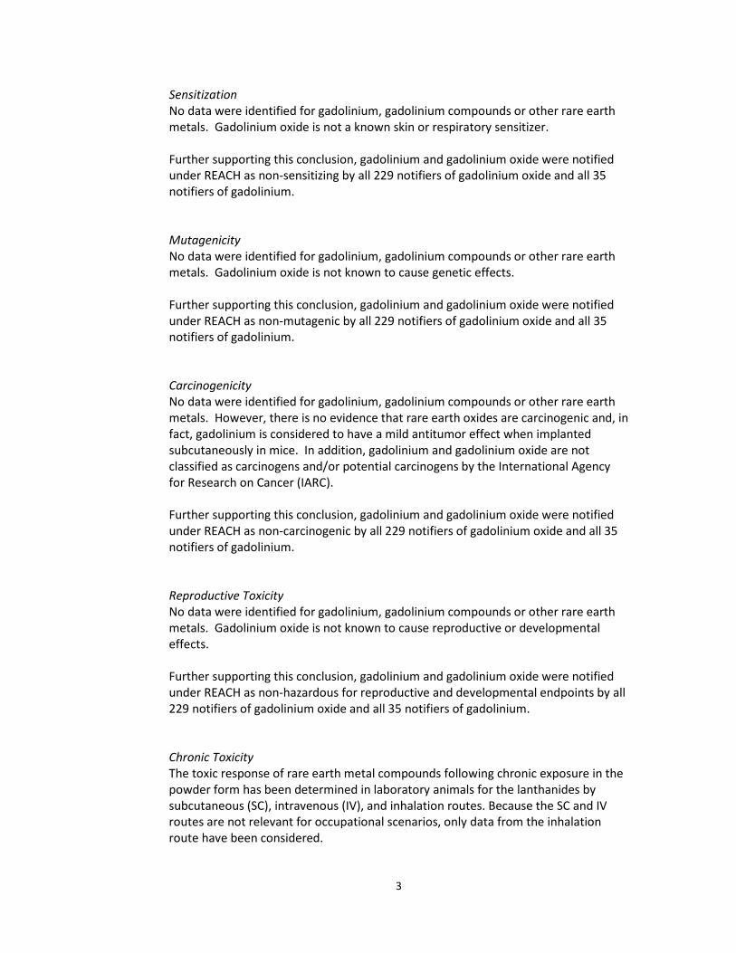
3
Sensitization No data were identified for gadolinium, gadolinium compounds or other rare earth metals. Gadolinium oxide is not a known skin or respiratory sensitizer. Further supporting this conclusion, gadolinium and gadolinium oxide were notified under REACH as non-sensitizing by all 229 notifiers of gadolinium oxide and all 35 notifiers of gadolinium. Mutagenicity No data were identified for gadolinium, gadolinium compounds or other rare earth metals. Gadolinium oxide is not known to cause genetic effects. Further supporting this conclusion, gadolinium and gadolinium oxide were notified under REACH as non-mutagenic by all 229 notifiers of gadolinium oxide and all 35 notifiers of gadolinium. Carcinogenicity No data were identified for gadolinium, gadolinium compounds or other rare earth metals. However, there is no evidence that rare earth oxides are carcinogenic and, in fact, gadolinium is considered to have a mild antitumor effect when implanted subcutaneously in mice. In addition, gadolinium and gadolinium oxide are not classified as carcinogens and/or potential carcinogens by the International Agency for Research on Cancer (IARC). Further supporting this conclusion, gadolinium and gadolinium oxide were notified under REACH as non-carcinogenic by all 229 notifiers of gadolinium oxide and all 35 notifiers of gadolinium. Reproductive Toxicity No data were identified for gadolinium, gadolinium compounds or other rare earth metals. Gadolinium oxide is not known to cause reproductive or developmental effects. Further supporting this conclusion, gadolinium and gadolinium oxide were notified under REACH as non-hazardous for reproductive and developmental endpoints by all 229 notifiers of gadolinium oxide and all 35 notifiers of gadolinium. Chronic Toxicity The toxic response of rare earth metal compounds following chronic exposure in the powder form has been determined in laboratory animals for the lanthanides by subcutaneous (SC), intravenous (IV), and inhalation routes. Because the SC and IV routes are not relevant for occupational scenarios, only data from the inhalation route have been considered.
4
Gadolinium oxide powder exhibits low to moderate toxicity following chronic exposure. Mice exposed to the substance in aerosol form from 20 - 120 days produced a trend in shorter lifespans. Evidence of accumulation of macrophages in the lungs, with interstitial thickening around the macrophages was observed in mice with exposure duration of 120 days. Evidence of degeneration was reported in macrophages containing gadolinium oxide, based on the presence of pyknosis and karyolysis. Calcification was reported in the alveolar basement membrane area and elastic laminea of small pulmonary vessels; however, it can still be stated that little to no pulmonary fibrosis was reported. Significant pathogenic potential has been reported for inhaled lanthanides, which is related to the type and physiochemical form of the material inhaled and the dose and duration of exposure. It can be concluded that progressive pulmonary fibrosis can be induced by stable rare earth metal powders. Further supporting this conclusion, gadolinium and gadolinium oxide were notified under REACH as non-hazardous for repeated dose endpoints by all 229 notifiers of gadolinium oxide and all 35 notifiers of gadolinium. Ecotoxicological Gadolinium oxide poses no persistence, bioaccumulation or ecotoxicity concerns. No ecotoxicity data were specifically identified for gadolinium or gadolinium compounds, but these are naturally occurring. Also metals as a class do not biodegrade so biodegradability is not a concern or expectations. The U.S. EPA reports a bioconcentration factor in green algae (Chlorella vulgaris) of 6.36 after 48 hours of exposure in fresh water, suggesting a lack of bioaccumulation potential. Gadolinium oxide was notified under REACH as very toxic to the aquatic environment with long-lasting effects by 93 of 229 notifiers. However, no data are available that supports this classification and it is a common practice in industry to conservatively assign this classification. None of the 35 notifiers of gadolinium metal indicated an environmental hazard. Conclusions: Gadolinium oxide is expected to have a low order of toxicity to human health and the environment, especially as incorporated into the massive/proppant form. Gadolinium oxide powder is reported to have toxicological and ecotoxicological effects, but upon review of existing, publicly-available data, classification as hazardous based on these data is not justified and not relevant to gadolinium oxide when incorporated into a proppant.

KM8 Hydraulic Fracturing Operations Waste Management Plan
Uncontrolled if printed KM8 WMP/Rev5/13-06-2017 Page 84
APPENDIX 6 – WASTE TREATMENT SPECIFICATION SHEETS

KM8 Hydraulic Fracturing Operations Waste Management Plan
Uncontrolled if printed KM8 WMP/Rev5/13-06-2017 Page 85
**This page has been intentionally left blank**
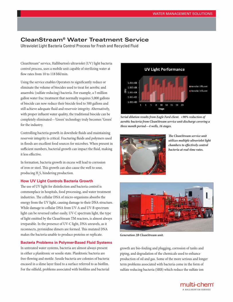
WATER MANAGEMENT SOLUTIONS
CleanStream® service, Halliburton’s ultraviolet (UV) light bacteria control process, uses a mobile unit capable of sterilizing water at flow rates from 10 to 118 bbl/min.
Using the service enables Operators to significantly reduce or eliminate the volume of biocides used to treat for aerobic and anaerobic (sulfate reducing) bacteria. For example, a 5 million gallon water frac treatment that normally requires 5,000 gallons of biocide can now reduce their biocide feed to 500 gallons and still achieve adequate fluid and reservoir integrity. Alternatively, with proper influent water quality, the traditional biocide can be completely eliminated—’Green’ technology truly becomes ‘Green’ for the industry.
Controlling bacteria growth in downhole fluids and maintaining reservoir integrity is critical. Fracturing fluids and polymers used in floods are excellent food sources for microbes. When present in sufficient numbers, bacterial growth can impact the fluid, making it less effective.
In formation, bacteria growth in excess will lead to corrosion of iron or steel. This growth can also cause the well to sour, producing H2S, hindering production.
How UV Light Controls Bacteria Growth The use of UV light for disinfection and bacteria control is commonplace in hospitals, food processing, and water treatment industries. The cellular DNA of micro-organisms absorbs the energy from the UV light, causing damage to their DNA structure. While damage to cellular DNA from UV-A and UV-B spectrum light can be reversed rather easily, UV-C spectrum light, the type of light emitted by the CleanStream TM reactors, is almost always irreparable. In the presence of UV-C light, DNA unravels, as it reconnects, pyrimidine dimers are formed. This mutated DNA makes the bacteria unable to produce proteins or replicate.
Bacteria Problems in Polymer-Based Fluid SystemsIn untreated water systems, bacteria are almost always present in either a planktonic or sessile state. Planktonic bacteria are free-flowing and motile. Sessile bacteria are colonies of bacteria encased in a slime layer fixed to a surface referred to as biofilm. For the oilfield, problems associated with biofilms and bacterial
CleanStream® Water Treatment ServiceUltraviolet Light Bacteria Control Process for Fresh and Recycled Fluid
Serial dilution results from Eagle Ford client. +90% reduction of aerobic bacteria from CleanStream service unit discharge covering a three month period—4 wells, 16 stages.
The CleanStream service unit utilizes multiple ultraviolet light chambers to effectively control bacteria at real-time rates.
Generation 2B CleanStream unit.
growth are bio-fouling and plugging, corrosion of tanks and piping, and degradation of the chemicals used to enhance production of oil and gas. Some of the more serious and longer term problems associated with bacteria come in the form of sulfate reducing bacteria (SRB) which reduce the sulfate ion
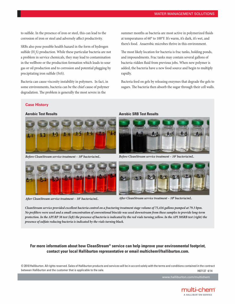
WATER MANAGEMENT SOLUTIONS
Before CleanStream service treatment – 108 bacteria/mL.
Aer CleanStream service treatment – 101 bacteria/mL.
Before CleanStream service treatment – 102 bacteria/mL.
Aer CleanStream service treatment – 100 bacteria/mL.
CleanStream service provided excellent bacteria control on a fracturing treatment stage volume of 75,416 gallons pumped at 79.3 bpm. No prefilters were used and a small concentration of conventional biocide was used downstream from these samples to provide long-term protection. In the API RP 38 test (le) the presence of bacteria is indicated by the red vials turning yellow. In the API 38SRB test (right) the presence of sulfate reducing bacteria is indicated by the vials turning black.
Case History Aerobic Test Results Aerobic SRB Test Results
© 2010 Halliburton. All rights reserved. Sales of Halliburton products and services will be in accord solely with the terms and conditions contained in the contract between Halliburton and the customer that is applicable to the sale.
www.halliburton.com/multichem
H07137 4/14
For more informatiom about how CleanStream® service can help improve your environmental footprint, contact your local Halliburton representative or email [email protected].
to sulfide. In the presence of iron or steel, this can lead to the corrosion of iron or steel and adversely affect productivity.
SRBs also pose possible health hazard in the form of hydrogen sulfide (H2S) production. While these particular bacteria are not a problem in service chemicals, they may lead to contamination in the wellbore or the production formation which leads to sour gas or oil production and to corrosion and potential plugging by precipitating iron sulfide (FeS).
Bacteria can cause viscosity instability in polymers. In fact, in some environments, bacteria can be the chief cause of polymer degradation. The problem is generally the most severe in the
summer months as bacteria are most active in polymerized fluids at temperatures of 60° to 100°F. It’s warm, it’s dark, it’s wet, and there’s food. Anaerobic microbes thrive in this environment.
The most likely location for bacteria is frac tanks, holding ponds, and impoundments. Frac tanks may contain several gallons of bacteria-ridden fluid from previous jobs. When new polymer is added, the bacteria have a new food source and begin to multiply rapidly.
Bacteria feed on gels by releasing enzymes that degrade the gels to sugars. The bacteria then absorb the sugar through their cell walls.
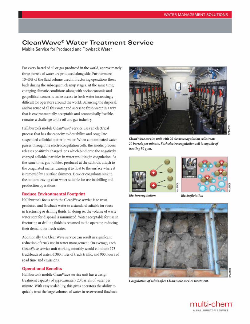
WATER MANAGEMENT SOLUTIONS
For every barrel of oil or gas produced in the world, approximately three barrels of water are produced along side. Furthermore, 10-40% of the fluid volume used in fracturing operations flows back during the subsequent cleanup stages. At the same time, changing climatic conditions along with socioeconomic and geopolitical concerns make access to fresh water increasingly difficult for operators around the world. Balancing the disposal, and/or reuse of all this water and access to fresh water in a way that is environmentally acceptable and economically feasible, remains a challenge to the oil and gas industry.
Halliburton’s mobile CleanWave® service uses an electrical process that has the capacity to destabilize and coagulate suspended colloidal matter in water. When contaminated water passes through the electrocoagulation cells, the anodic process releases positively charged ions which bind onto the negatively charged colloidal particles in water resulting in coagulation. At the same time, gas bubbles, produced at the cathode, attach to the coagulated matter causing it to float to the surface where it is removed by a surface skimmer. Heavier coagulants sink to the bottom leaving clear water suitable for use in drilling and production operations.
Reduce Environmental FootprintHalliburton’s focus with the CleanWave service is to treat produced and flowback water to a standard suitable for reuse in fracturing or drilling fluids. In doing so, the volume of waste water sent for disposal is minimized. Water acceptable for use in fracturing or drilling fluids is returned to the operator, reducing their demand for fresh water.
Additionally, the CleanWave service can result in significant reduction of truck use in water management. On average, each CleanWave service unit working monthly would eliminate 175 truckloads of water, 6,300 miles of truck traffic, and 900 hours of road time and emissions.
Operational BenefitsHalliburton’s mobile CleanWave service unit has a design treatment capacity of approximately 20 barrels of water per minute. With easy scalability, this gives operators the ability to quickly treat the large volumes of water in reserve and flowback
CleanWave® Water Treatment ServiceMobile Service for Produced and Flowback Water
CleanWave service unit with 20 electrocoagulation cells treats 20 barrels per minute. Each electrocoagulation cell is capable of treating 50 gpm.
Electrocoagulation
HAL3
2902
Electroflotation
Coagulation of solids after CleanWave service treatment.
HAL3
2409
HAL3
2408
HAL3
2411

WATER MANAGEMENT SOLUTIONS
Post CleanWave treatment.
pits and, depending on the operation, to treat flowback and produced water online during a fracturing operation.
The CleanWave service was designed to remove suspended solids, oil, other insoluble organics, and bacteria from the water. The operating conditions are regulated depending on the total dissolved solids (TDS) present in the water.
Key Features• 99% reduction in total suspended solids (TSS)
• Treats water with TDS ranging from 100 – 300,000 mg/L
• Coagulates particles < 1 micron
• Reduces turbidity to < 10 NTU
• Non-polymer based water treatment contributes up to 75% reduction in sludge generation
• Breaks emulsions
• Removal of divalents and heavy metals*
• Fully automated
• Scalable
• Self-cleaning
• One operator per shift
Most effective at treating the following contaminants:
• TSS
• Total petroleum hydrocarbons (TPH)
• Turbidity
• Bacteria
* Partial removal only. Complete removal requires further treatment.
CleanWave water treatment service effectively removes oil from contaminated water.
General Specifications
Power Requirement 150 kVA / 120 kWThroughput 20 BPMHydraulic Capacity 1,000 GPMWeight 48,000 lb
Dimensions 9’L X 42’W X 12’H
© 2013 Halliburton. All rights reserved. Sales of Halliburton products and services will be in accord solely with the terms and conditions contained in the contract between Halliburton and the customer that is applicable to the sale.
www.halliburton.com/multichem
H07734 4/14

KM8 Hydraulic Fracturing Operations Waste Management Plan
Uncontrolled if printed KM8 WMP/Rev5/13-06-2017 Page 86
APPENDIX 7 – MANAGEMENT OF RADIOACTIVE WASTE

KM8 Hydraulic Fracturing Operations Waste Management Plan
Uncontrolled if printed KM8 WMP/Rev5/13-06-2017 Page 87
**This page has been intentionally left blank**
………………
Tech
nica
l Rep
ort
BAT STATEMENT RELATED TO THEDISPOSAL OF RADIOACTIVE WASTE
FROM THIRD ENERGY UK GASLTD’S KIRBY MISPERTON A
WELLSITEStudsvik Contract Reference: P0744
Studsvik Report Reference: P0744/TR/001
Revision: C
Date: 14/05/15
Client Ref: KM8-UNC-0021
Prepared By: ………………………………………….Nick ChambersRadiation Protection Adviser/RadioactiveWaste Adviser
Date: 14/05/15
Checked By:………………………….
Radiation Protection Adviser/Senior WasteManagement Consultant
Date: 14/05/15
Checking Level: Two
Approved By:………………………………………….Andrew LakerConsultancy Services Manager – WasteManagement
Date: 14/05/15
Studsvik UK LimitedUnit 14Princes Park4th AvenueTeam Valley Trading EstateGatesheadTyne & Wear. NE11 0NF
Report Reference: P0744/TR/001Revision: C
Date: 14/05/15
Page 2
REVISION SHEETRev. Description Revised By Checked By Approved By
A First Issue N Chambers R Strange A Laker
B Second Issue – amendment afterone round of customer
comments
N Chambers R Strange A Laker
C Third Issue – amendmentfollowing revision of flowback
volumes & options
N Chambers V Lilley A Laker
LIMITATIONS
This report has been prepared by Studsvik UK Limited in their professional capacity as Consultants, with all reasonable skill, careand diligence within the terms of the Contract with the Client. The advice and opinions in this report are based upon the informationmade available at the date of this report and on current UK standards, codes and legislation. The contents of this report do not, inany way, purport to include any manner of legal advice or opinion. This report has been produced in accordance with the terms andconditions detailed within client Purchase Order number POR005047.
Should the Client release this report to a Third Party, that Third Party does not acquire any rights, contractual or otherwise, whatsoeveragainst Studsvik UK Limited and accordingly, Studsvik UK Limited assumes no duties, liabilities or obligations to that Third Party
Report Reference: P0744/TR/001Revision: C
Date: 14/05/15
Page 3
EXECUTIVE SUMMARYThis Best Available Techniques (BAT) document has been prepared on behalf of Third EnergyUK Gas Ltd as part of an application to the Environment Agency under the EnvironmentalPermitting (England and Wales) Regulations 2010 to allow for the accumulation and disposal ofNaturally-Occurring Radioactive Material (NORM).
The potential presence of NORM in aqueous waste on the Kirby Misperton A (KMA) wellsite isrelated to the potential dissolution of radionuclides within the targeted formations and theirsubsequent transport to the surface during operations performed in relation to well KM8.Elements such as uranium, radium and radon are potentially dissolved in relatively lowconcentrations during reactions between the water and rock matrix. The dissolved radionuclideswithin the formations may be transported to the surface within the ‘flowback water’ of the KM8hydraulic fracturing operations. Additionally, precipitates may be formed as a result ofsubsequent chemico-physical changes occurring within the water, however, these volumes areexpected to be negligible.
There is a potential for the contamination of solid components/materials during the phaseseparation of material and the treatment of flowback water on the surface. However, due to therelatively low NORM concentrations anticipated, and the relatively short duration of the proposedoperations, the works are not expected to give rise to any significant contamination issues.
With regard to minimising the arisings of aqueous radioactive waste, a BAT is considered to bethe on-site treatment of the flowback (in this case using a process of electrocoagulation), to allowfor its re-use during subsequent hydraulic stimulations; however, the potential for this approachwill be dependent upon the physical and chemical make-up of the flowback water, thedetermination of which will only be possible once site operations commence. Assuming on-sitetreatment is feasible, a final waste water volume (which will be accumulated at the surface atclose of the fifth phase of hydraulic fracturing) of approximately 675 m3 (comprising final flowbackwaste water and accumulated treatment waste waters) has been estimated for the KM8 hydraulicfracturing operation. Should on-site treatment be unfeasible, a total flowback water volume ofapproximately 1,646 m3 has been estimated.
Aqueous waste will be transported off-site to a bespoke, permitted industrial waste watertreatment facility. This is the preferred option for treatment, as identified by this BAT study andwill ensure that the aqueous waste will be managed effectively in accordance with currentregulations and minimise any environmental impact associated with the waste. It has beendemonstrated within this report that the treatment process will not give rise to any significantradiological exposure to members of the public or the environment, and is considered to be thebest practicable environmental option.
The degree to which generation of solid waste occurs during the KM8 hydraulic fracturingoperation is uncertain, however, disposal options have been considered for (what is anticipatedas being) a relatively insignificant waste stream.
A summary of the waste management arrangements is also provided, outlining the necessaryrequirements for compliance with both the conditions of the Environmental Permitting (Englandand Wales) Regulations 2010 (EPR10) permit, and the applicable requirements of the IonisingRadiations Regulations 1999 (IRR99).
Report Reference: P0744/TR/001Revision: C
Date: 14/05/15
Page 4
GLOSSARY
BAT Best Available TechniqueEA Environment AgencyEMMP Environmental Management and Monitoring PlanEPR10 Environmental Permitting Regulations 2010 (as amended)IRR99 Ionising Radiations Regulations 1999KMA Kirby Misperton A WellsiteKM8 Kirby Misperton 8 hydrocarbon wellLAIP Letter of Agreement in PrincipleLLW Low Level WasteNORM Naturally-Occurring Radioactive MaterialOSPAR Oslo Paris Convention for the Protection of the Marine Environment
of the North-East AtlanticRIA Radiological Impact AssessmentRPA Radiation Protection AdviserRPS Radiation Protection SupervisorRSCR Radiological Site Condition ReportRSR Radioactive Substances RegulationRWA Radioactive Waste AdviserTSS Total Suspended SolidsWwTW Wastewater Treatment Works
Report Reference: P0744/TR/001Revision: C
Date: 14/05/15
Page 5
CONTENTS
1 INTRODUCTION ............................................................................ 61.1 BACKGROUND................................................................................................. 61.2 SITE DETAILS................................................................................................... 61.3 BAT DEFINITION AND REQUIREMENTS........................................................ 6
2 JUSTIFICATION OF PRACTICES.................................................. 83 DESCRIPTION OF WASTE STREAMS.......................................... 83.1 UNTREATED & UN-RECYCLED FLOWBACK WATER.................................... 83.2 FLOWBACK WATER TREATMENT.................................................................. 93.3 ASSUMED RADIOACTIVE WASTE INVENTORY .......................................... 103.4 WASTE WATER STORAGE ........................................................................... 103.5 WASTE WATER CHARACTERISATION ........................................................ 103.6 MISCELLANEOUS SOLID WASTE................................................................. 10
4 WASTE MANAGEMENT OPTIONS ASSESSMENT .................... 115 DISPOSAL OPTIONS ASSESSMENT.......................................... 125.1 WASTE ROUTE SELECTION FOR AQUEOUS WASTE................................ 125.1.1 Direct discharge from site into a watercourse.................................................. 125.1.2 Direct discharge from site into the public sewer .............................................. 125.1.3 Transfer to WwTW........................................................................................... 125.1.4 Transfer to a bespoke RSR Permitted waste treatment facility........................ 125.1.5 Transfer to incinerator...................................................................................... 135.2 WASTE ROUTE SELECTION FOR SOLID WASTE ....................................... 135.2.1 Disposal to landfill disposal facility................................................................... 135.2.2 Disposal to LLW disposal facility ..................................................................... 135.2.3 Transfer to treatment facility ............................................................................ 135.3 SUMMARY & BAT JUSTIFICATION ............................................................... 135.3.1 Aqueous waste ................................................................................................ 135.3.2 Solid waste ...................................................................................................... 14
6 ENVIRONMENTAL IMPACT ASSESSMENTS ............................. 147 GENERAL WASTE MANAGEMENT CONSIDERATIONS............ 157.1 MINIMISATION OF ACCUMULATING WASTE ACTIVITIES AND VOLUMES157.2 CONTAMINATION MONITORING .................................................................. 157.3 STORAGE ARRANGEMENTS........................................................................ 157.4 WASTE CHARACTERISATION ...................................................................... 167.5 SQEP & TRAINING ......................................................................................... 167.6 MAINTENANCE AND AUDIT OF FACILITIES ................................................ 167.7 MANAGEMENT OF RADIATION WORK ........................................................ 167.8 WORKING ARRANGEMENTS........................................................................ 17
8 CONCLUSIONS ........................................................................... 179 REFERENCES ............................................................................. 17
Report Reference: P0744/TR/001Revision: C
Date: 14/05/15
Page 6
1 INTRODUCTION
1.1 Background
The following Best Available Techniques (BAT) Statement has been prepared as part of anapplication for a Permit to perform a Radioactive Substances Regulation (RSR) activity, inaccordance with the Environmental Permitting (England and Wales) Regulations 2010 (asamended) [1]. The practice relates to on-shore oil and gas exploratory operations to be performedby Third Energy UK Gas Ltd on the Kirby Misperton A wellsite, and relates primarily to hydraulicfracturing to be performed from the KM8 well. The requirement for an RSR permit is related tothe potential generation of radioactive waste during site operations as a result of the inadvertentextraction of naturally-occurring radioactive material (NORM) from the target formations.
1.2 Site details
The KM8 hydraulic fracturing operation and subsequent production testing will be undertaken atthe following location:
Kirby Misperton A WellsiteOff Habton RoadKirby MispertonNorth YorkshireYO17 6XSEngland
National Grid Ref: SE 771789Site Area: 1.465 ha
1.3 BAT definition and requirements
Within the Environment Agency EPR guidance [2] BAT is defined as:
“The use of the best available techniques will emphasise the use of non-waste technology, ifavailable.”
The term "best available techniques" means the latest stage of development (state of the art) ofprocesses, of facilities or of methods of operation which indicate the practical suitability of aparticular measure for limiting discharges, emissions and waste. In determining whether a set ofprocesses, facilities and methods of operation constitute the best available techniques in generalor individual cases, special consideration will be given to:
• comparable processes, facilities or methods of operation which have recently beensuccessfully tried out;
• technological advances and changes in scientific knowledge and understanding;• the economic feasibility of such techniques;• time limits for installation in both new and existing plants;• the nature and volume of the discharges and emissions concerned.
Report Reference: P0744/TR/001Revision: C
Date: 14/05/15
Page 7
It therefore follows that what is "best available techniques" for a particular process will changewith time in the light of technological advances, economic and social factors, as well as changesin scientific knowledge and understanding.
If the reduction of discharges and emissions resulting from the use of best available techniquesdoes not lead to environmentally acceptable results, additional measures have to be applied.
"Techniques" include both the technology used and the way in which the installation is designed,built, maintained, operated and dismantled.”
The definition notes that consideration should be given to the nature and volumes of thedischarges under question.
The aim of the concept of BAT is to optimise, and thus minimise, the activity of radioactivityhandled, the amount of contamination generated, and the activity of waste requiring disposal, sominimising the activity which is ultimately discharged to the environment.
Part of the concept of BAT is that users should consider the work procedures and the resultingradioactive waste generated before work commences, to ensure the minimisation of waste at allstages. BAT is an on-going process with reviews both periodically and whenever there is asubstantive change in circumstances. The Environment Agency (EA) requires that the BATapproach is adopted in an appropriate manner at a level which is proportionate to theenvironmental risk. There is no de minimis level below which BAT does not apply, proportionalitybeing a key principle.
Key elements include justifying the use of radioactive material (not applicable to the Permitapplication in question; see Section 2), performing tasks efficiently without creating unnecessarywaste and decay-storing solid waste where practicable. All waste minimisation procedures needto take account of such factors as,
practicality operator safety monetary cost, and benefits to the environment of reduced discharges and disposals.
Permits granted under EPR10 require operators to use BAT to minimise the activity of radioactivewaste produced that will require disposal under the permit.
The application of BAT requires operators to use best available techniques in the design andoperational management of their facilities, to minimise discharges and disposals of radioactivewaste. The focus is to ensure a high standard of protection for the public and the environment.
BAT is applied to such aspects as minimising waste creation, abating discharges, and themonitoring of plant, discharges and the environment for radioactivity. It takes account of suchfactors as the availability and cost of relevant measures, operator safety and the benefits ofreduced discharges and disposals in relation to doses to workers, the public and non-humanbiota.
Third Energy UK Gas Ltd has appointed Studsvik UK Limited as Radiation Protection Adviser(RPA) and Radioactive Waste Adviser (RWA), to provide advice on the management ofradioactive waste, and to support Third Energy with regard to RSR permit compliance associatedwith KMA wellsite operations.
Report Reference: P0744/TR/001Revision: C
Date: 14/05/15
Page 8
This BAT statement has been drafted in support of the application for an EPR Permit to allow forthe potential accumulation (and subsequent disposal) of NORM arising from hydraulic stimulationoperations on a pre-drilled hydrocarbon exploration site. The following sections address thevarious requirements in considering whether BAT are being applied to the practice andassociated waste streams.
2 JUSTIFICATION OF PRACTICES
A preliminary consideration with regard to radiological protection is whether the operations whichwill generate the radioactive waste, and which could increase the exposure of individuals, arejustified, in accordance with the Justification of Practices Involving Ionising Radiation Regulations2004 [3]. However, the operations are not considered to be a ‘practice’, as defined within the ECBasic Safety Standard Directive [4], given that the natural radiation sources in question are notbeing used for their radioactive, fissile or fertile properties. Therefore, further consideration of theJustification regulations is not required.
3 DESCRIPTION OF WASTE STREAMS
The potential presence of NORM in aqueous waste, due to the dissolution of radionuclides withinthe rock formations (by naturally present, or injected, water), is an unavoidable consequence ofhydrocarbon exploration, including the process of hydraulic fracturing.
Contamination may arise as a result of dissolution of radionuclides within the formation, and theirsubsequent transport to the surface, either within ‘produced water’ naturally released from theformation(s), or within ‘flowback’ water which may return to the surface following injection duringwell preparation or hydraulic stimulation (fracturing) operations. There is also the potential for thecontamination of solid materials (for example, phase-separator components), and/or build-up ofsludges or insoluble scales/coatings within pipework/components.
The potential for (EPR10) in-scope radioactive substances on the KMA site relates purely toradioactive waste, which may be inadvertently generated during the proposed site operations.No use of radioactive material is to occur on the site (i.e. radionuclides are not to be used fortheir radioactive, fertile or fissile properties), and the requirements of the EPR10 extend onlyinsofar as the regulations apply to radioactive waste. The only waste-related procedures whichrequire consideration are the storage and transfer/disposal of aqueous radioactive waste, andthe potential generation of solid radioactive waste through contamination of equipment/PPEwhich will also require appropriate treatment/disposal. Given the relatively low concentrations ofNORM anticipated, operations are not expected to give rise to any significant contaminationissues.
With regard to the potential generation of aqueous waste two scenarios are considered, whichare discussed in further detail in sections 3.1 and 3.2; firstly (section 3.1), it is assumed that fortechnical reasons the recycling and re-use of flowback water is not possible, and all flowbackwater is simply accumulated on-site prior to consignment to an off-site treatment facility. Secondly(section 3.2), it is assumed that treatment of the flowback water is technically feasible, allowingfor its re-use during subsequent stages.
3.1 Untreated & un-recycled flowback water
The anticipated aqueous waste is flowback water, hydraulic fracture treatment fluid which will bereleased from the target formations immediately following each of the five proposed zonal,fracture stages. Relatively small volumes of flowback water may also be released graduallyduring subsequent phases of the operation, specifically well testing and production testing. It is
Report Reference: P0744/TR/001Revision: C
Date: 14/05/15
Page 9
anticipated that the return fraction [including contribution of any produced water] of injected fluidvolume will likely be 30 %; however, it has been pessimistically assumed that 50 % of the injectedfluid volume will return to the surface. A total fluid injection volume of 3,291 m3 is proposed,potentially giving rise to a flowback waste water volume of 1,646 m3. The total estimated volumeof waste flowback water is considered to be a conservative (over-estimate) of the volume likelyto be produced from the site. There is significant uncertainty associated with the potential returnrate, and it’s pertinent to note that less pessimistic calculations estimated waste water volumesas low as 450 m3.
The elevated concentrations of NORM present within the flowback waters relate predominantlyto radioisotopes of radium (and associated progeny), which find their way into the water due totheir chemical solubility. Elevated concentrations of radon progeny may also be present, due todissolved Rn-222 (radon) and, to a lesser extent, Rn-220 (thoron) gas. The waste flowback watermay also contain significant quantities of dissolved solids, and also relatively small volumes ofsuspended solids.
Based on the maximum anticipated uranium and thorium concentrations within the formation inquestion, and based on knowledge of radium dissolution within other formations (and assuminga similar extent of dissolution within the KM8 target formations), it has been estimated (worst-case) that the flowback water generated during each proposed stage of hydraulic stimulationcould contain Ra-226 at a maximum specific activity concentration of 140 Bq L-1. Similarly, it hasbeen estimated (worst-case) that the produced waters could contain Ra-228 at a maximumspecific activity concentration of 14 Bq L-1.
Based on the maximum estimated volume of approximately 1,646 m3, this equates toapproximately 230 and 23 MBq of Ra-226 and Ra-228, respectively, within the waste flowbackwater.
3.2 Flowback water treatment
In order to minimise waste arisings, the re-use of the flowback fluid in subsequent injections isthe preferred option. However, treatment of the flowback water (for reasons associated with thenon-radioactive characteristics of the water) will be necessary, prior to any such recycling/re-use.Subject to the physical and chemical make-up of the flowback water (to be determined onceoperations have commenced), a decision will be taken on the potential for treatment usingHaliburton’s Multi-Chem® CleanWave® technology. Similarly, the waste flowback water whichmay arise following the fifth and final stimulation may be treated, prior to any transfer/disposal.
The treatment process utilises the technique of electrocoagulation, with the primary aim ofremoving Total Suspended Solids (TSS), by up to 99 %. The process is also claimed to effectthe partial removal of Group II metals (i.e. Ra2+) and heavy metals. As such, there is the potentialfor the waste streams produced as a result of the proposed electrocoagulation process to becontaminated with NORM.
The electrocoagulation process generates a sludge waste, which in terms of volume is expectedto be approximately 5-10 % of the flowback water volume undergoing treatment. The sludge isexpected to comprise 85 % liquid (water) and 15 % solids (removed TSS, and any additionalprecipitate generated during the treatment process), and for the purpose of the EPR10 permitapplication is considered a liquid.
Although the treatment process is an established, proprietary technique, there is uncertainty asto the likely efficiency of radium removal, which will be dependent on several local factors(including the chemistry of both the feed water and the flowback water). Based on the estimated
Report Reference: P0744/TR/001Revision: C
Date: 14/05/15
Page 10
fluid injection profile, and a produced ‘sludge’ volume of between 5 and 10 % of the treated watervolume, it has been estimated that the treatment process will generate a total sludge wastevolume of between 82-165 m3. For the purpose of this assessment, it has been conservativelyassumed that the technique will be 100 % efficient in the removal of radium from the flowbackwater, and the potential electrocoagulation sludge waste will contain maxima of approximately230 and 23 MBq of Ra-226 and Ra-228, respectively.
The proposed waste water treatment will also involve exposure to ultra-violet light, in order tominimise the potential for biological activity within the hydraulic stimulation fluids. However, thistreatment stage is not expected to produce any potentially NORM-contaminated aqueous waste.
3.3 Assumed radioactive waste inventory
For the purpose of the remainder of this document, and also in the determination of suitableactivities to be included within the EPR10 RSR application, the maximum amount of radioactivitythat could be generated via either of the processes outlined in Sections 3.1 and 3.2 will be used(i.e. 230 and 23 MBq of Ra-226 and Ra-228, respectively). It is considered good practice to alsoallow for a degree of headroom in the activities; therefore, the activity limits used for the RSRpermit application and this BAT statement for Ra-226 and Ra-228 within accumulated aqueouswaste are 300 and 30 MBq, respectively*.
3.4 Waste water storage
Waste water accumulated on site will be stored in closed, steel storage tanks. The maximumstorage capacity of the tanks is in excess of 1,000 m3 and is therefore suitable for the expectedrate of generation of flowback water resulting from the hydraulic fracturing processes on the KMAwellsite. Given the significant waste storage capacity available on site, it is extremely unlikely thatthe maximum storage capacity will be approached. Nevertheless, should that be the case thenthe well shall be shut-in until the accumulated waste flowback water can be taken off-site fortreatment and disposal, creating further storage capacity.
3.5 Waste water characterisation
Any flowback waste water produced during the hydraulic stimulations (or any flowback/producedwater generated at a later stage of site operations), and any electrocoagulation waste waterproduced as a result of potential waste water treatment, will be characterised prior to anytransfer/disposal from site, as detailed in Section 7.4.
3.6 Miscellaneous solid waste
Given the potential for the formation of NORM-contaminated scales/coatings within pipework andassociated apparatus, and/or the NORM contamination of phase separator and potentialtreatment module equipment/material, allowance has also been made for the generation of arelatively small quantity of solid radioactive waste. Accumulation and disposal of a nominal
* Although the waste activity calculations estimate potential Ra-226 and Ra-228 activities of approximately 230 and 23 MBq, a degreeof head-room will be requested within the RSR application, given the uncertainties associated with the specific activities of thepotential flowback water.
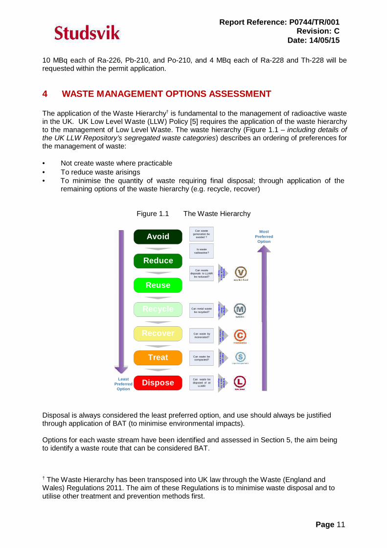
Report Reference: P0744/TR/001Revision: C
Date: 14/05/15
Page 11
Segregate
VVLLWO
utof
Scope
Segrega
teM
etal;conside
rtype
Segregate
was
tefor
disposal
Segregate
Combus
tibleS
egregate
Combus
tible
10 MBq each of Ra-226, Pb-210, and Po-210, and 4 MBq each of Ra-228 and Th-228 will berequested within the permit application.
4 WASTE MANAGEMENT OPTIONS ASSESSMENT
The application of the Waste Hierarchy† is fundamental to the management of radioactive wastein the UK. UK Low Level Waste (LLW) Policy [5] requires the application of the waste hierarchyto the management of Low Level Waste. The waste hierarchy (Figure 1.1 – including details ofthe UK LLW Repository’s segregated waste categories) describes an ordering of preferences forthe management of waste:
Not create waste where practicable To reduce waste arisings To minimise the quantity of waste requiring final disposal; through application of the
remaining options of the waste hierarchy (e.g. recycle, recover)
Figure 1.1 The Waste Hierarchy
AvoidCan waste
generation beavoided ?
MostPreferred
Option
Reduce
Reuse
Is wasteradioactive?
Can wastedisposals to LLWR
be reduced?
LeastPreferred
Option
Recycle
Recover
Treat
Dispose
Can metal wastebe recycled?
Can waste byincinerated?
Can waste becompacted?
Can waste bedisposed of at
LLWR
Disposal is always considered the least preferred option, and use should always be justifiedthrough application of BAT (to minimise environmental impacts).
Options for each waste stream have been identified and assessed in Section 5, the aim beingto identify a waste route that can be considered BAT.
† The Waste Hierarchy has been transposed into UK law through the Waste (England andWales) Regulations 2011. The aim of these Regulations is to minimise waste disposal and toutilise other treatment and prevention methods first.
Report Reference: P0744/TR/001Revision: C
Date: 14/05/15
Page 12
5 DISPOSAL OPTIONS ASSESSMENT
Given that the potential waste arisings are simply the bi-product of a NORM industrial activity,and there are currently no proprietary techniques which would prevent the dissolution of radiumfrom the formation(s), there is no scope for the prevention of primary waste generation. Thereforethis BAT assessment simply relates to the disposal of the potential arisings (this section), andthe measures to be adopted to minimise the environmental impact of potential contaminationassociated with the handling and storage of NORM-contaminated waste (Section 7). Unlessdetermined as being technically unfeasible, the treatment and recycling/re-use of waste waterwill be performed wherever possible, to minimise the volume of waste arisings.
5.1 Waste route selection for aqueous waste
5.1.1 Direct discharge from site into a watercourse
Direct discharge from site into a watercourse is not considered a viable option, given that there’scurrently no infrastructure in place to potentially allow for such a discharge. Additionally, theenvironmental impact of such a discharge is likely to be significant, given the relatively low flow-rate of the nearest water course‡.
Given the relatively small volume of waste water anticipated, and the fact that no proven,commercially-available, proprietary treatment technology is currently available, any necessaryon-site pre-treatment to remove radium prior to discharge is not considered as beingeconomically viable.
5.1.2 Direct discharge from site into the public sewer
Direct discharge from site is not considered to be a viable option, given that there’s currently noinstalled sewer connection on the site, and installation of such is not considered as beingeconomically viable given the relatively low volume of waste anticipated.
5.1.3 Transfer to WwTW
Given the difficulties associated with potential waste acceptance encountered elsewhere by theindustry in the UK, transfer to a Wastewater Treatment Works (WwTW) is not considered a viableoption. If this route were to be made available, the associated environmental impact is notexpected to be significant, being principally associated with the transportation of the waste.
5.1.4 Transfer to a bespoke RSR Permitted waste treatment facility
With regard to the waste hierarchy, off-site transfer of waste for treatment is clearly the preferredoption, given that the process of treatment should minimise any environmental impact associatedwith the waste, and is clearly the preferred option for the KMA wellsite operation. A Letter ofAgreement in Principle (LAIP) has been obtained for the treatment of the aqueous waste at an
‡ An assessment has been performed using the environmental regulators’ Initial Radiological Assessment Methodology. Given thatno data is available for the nearest watercourse [numerous small streams and land drains appear to be shown on Ordnance SurveyMaps in the area surrounding the site], a watercourse flow-rate of 0.1 m3 s-1 was initially assumed, and the proposed discharge wasestimated to lead to a potential Angling Family exposure of approximately 480 microSv y-1. Assuming discharge was made possibleinto the Pickering Beck @ Ings Bridge (Nearest Gauging Station; No. 27056; flow data 1974-2013; mean flow-rate 0.866 m3 s-1;source National River Flow Archive @ www.ceh.ac.uk), the proposed discharge would lead to an Angling Family exposure ofapproximately 67 microSv y-1. Potential environmental impacts associated with non-radiological components of the waste would alsorequire consideration, and could be a limiting a factor.
Report Reference: P0744/TR/001Revision: C
Date: 14/05/15
Page 13
EPR10-permitted facility. If this route were to be chosen, the associated environmental impact isnot expected to be significant (see Section 6), being principally associated with the transportationof the waste.
5.1.5 Transfer to incinerator
Given the relatively low volume of waste which will potentially be generated, transfer to anincinerator facility is considered a viable option, dependant on the concentrations of non-radiological contaminants within the waste. If this route were to be taken, the associatedenvironmental impact is not expected to be significant, being principally associated with thetransportation of the waste.
5.2 Waste route selection for solid waste
The generation of solid waste is not anticipated during the exploratory phase of operations. Assuch, detailed consideration of disposal options is not considered necessary. However, thefollowing options would be considered, being dependent upon the specific activity concentrationsof the waste.
5.2.1 Disposal to landfill disposal facility
Conditionally-exempt Type 1 NORM waste (having a NORM waste concentration of ≤5 Bq g-1)could be disposed of to a licenced landfill, subject to consideration of the potential non-radiological contaminants.
5.2.2 Disposal to LLW disposal facility
Low-level waste (LLW) having a total activity concentration (of EPR10 radionuclides) of≤200 Bq g-1 could be disposed of to one of two UK landfill facilities, subject to consideration ofthe potential non-radiological contaminants.
5.2.3 Transfer to treatment facility
Where separation of radiological contamination was considered possible (for example by high-pressure water-jetting), and economically viable, transfer of the waste to a suitable treatmentfacility would be considered (and would be the preferred approach from the perspective of thewaste hierarchy). It is pertinent to note that generation of such waste is only likely to occur afterdaily production for several years, and in any event, when the equipment reaches end-of-life andbecomes waste. The generation of such waste on the KMA wellsite is therefore highlyimprobable, however the raising of an LAIP for the treatment of contaminated equipment hashowever been sought as a precautionary measure.
5.3 Summary & BAT justification
5.3.1 Aqueous waste
Wherever technically possible, flowback will be recycled and reused during subsequent stagesof hydraulic stimulation, thereby minimising the volume of waste water which will ultimatelyrequire treatment and/or disposal.
Report Reference: P0744/TR/001Revision: C
Date: 14/05/15
Page 14
Incineration is potentially a BAT, however this route is simply a disposal, and does not involvetreatment of the waste. Disposal is the least preferred option within the waste hierarchy and thetransfer of aqueous waste to a licenced waste treatment facility is identified as the preferredoption. Transfer to a bespoke treatment facility, involving pre-treatment prior to any disposal,immobilises the NORM in a solid filter cake suitable for disposal to landfill and ensures thatpotential environmental impacts are minimised. This option therefore also aligns with the conceptof the waste hierarchy.
5.3.2 Solid waste
Given that generation of solid LLW is not anticipated during the proposed KMA wellsiteoperations, treatment and disposal options will only be considered in detail (following wastecharacterisation) should any solid waste actually be generated. In summary, the solid wastewould be characterised and sent to a permitted waste disposal facility (if considered to be non-exempt Low-level Waste), or to a licenced landfill facility (if considered as being either Out-of-Scope of the requirements of the EPR10, or as conditionally-exempt Type 1 NORM waste).
6 ENVIRONMENTAL IMPACT ASSESSMENTS
Although no liquid discharges from the site are proposed, in order to demonstrate that thepotential transfer of aqueous waste to a treatment facility is indeed a BAT, confirmation of thepotential radiological environmental impacts are presented below.
The potential EPR10-permitted treatment site which can receive aqueous waste from theexploration sites utilises an acid/alkali treatment process to treat the waste waters, and producesan inert, non-hazardous solid filter-cake residue. The process removes approximately 90 and 42% of the radium and lead, respectively. The phase conversion results in the production of solidmaterial which is estimated to contain NORM at activity concentrations which will render thematerial Out-of-Scope of the requirements of the EPR10.
The site has been permitted for a number of years to accumulate, treat and dispose of NORMwaste. As such, a Radiological Impact Assessment (RIA) is in place to cover the site’s existingPermit limits (which allows for receipt of significantly higher activities, relative to those detailedwithin this BAT statement). However, to confirm that the treatment of the aqueous waste detailedwithin this BAT statement will result in minimal environmental impact, an RIA has beenperformed, based on the anticipated waste activities. It is estimated that aqueous waste disposalfrom site (following waste treatment) will potentially result in an effective dose of approximately0.8 Sv y-1 to the most exposed group (Farming Family).
The estimated dose represents approximately 0.26 % of the 300 µSv y-1 currently recommendedby Public Health England as the dose constraint applicable to public exposure from a single newsource [7]. The fatality risk (associated with one year’s exposure) is calculated to be 3.9E-08(approximately 1 in 26,000,000) based on a fatality risk factor of 5 % per Sv.
It is therefore considered that the method of disposal involving transportation to a waste treatmentfacility and removal of the majority of the NORM within a solid filter-cake residue (suitable forlandfilling) is considered to be the best practicable environmental option.
Report Reference: P0744/TR/001Revision: C
Date: 14/05/15
Page 15
7 GENERAL WASTE MANAGEMENT CONSIDERATIONS
7.1 Minimisation of accumulating waste activities and volumes
Waste volumes accumulated on the sites are dictated by the rate at which aqueous material istransported to the site surface, and the rate at which items of equipment become contaminatedwith solid NORM residues (if at all).
Removal of aqueous waste to an EPR10-permitted waste treatment facility (within road tankers)will occur as soon as is reasonably practicable.
As soon as practicable, after identification and characterisation, low-level solid waste will betransferred to a suitable EPR10-permitted treatment or disposal facility. Waste which is Out-of-Scope of the EPR10, or which is considered to be conditionally-exempt Type 1 NORM waste,will be consigned to a licenced landfill facility, or considered for recycling/re-use, as appropriate.
7.2 Contamination monitoring
A number of baseline samples of environmental media will be taken prior to commencement ofworks on the sites, to determine background concentrations of radionuclides in the local area. Abackground contamination survey will also be performed (using a suitable alpha/betacontamination monitor). A contamination monitoring programme will be devised, to ensure thatany significant (albeit improbable) environmental contamination is promptly identified. This willinclude alpha/beta contamination monitoring of key areas/surfaces, including:
Well-head (and immediately surrounding site surface); Separator equipment (external surfaces, and any internal surfaces accessible for
maintenance/access (and immediately surrounding site surface)); Storage tanks (internal surfaces where practicable, external valves and immediately
surrounding site surface); Electrocoagulation treatment module.
Consignments of waste flowback water and electrocoagulation waste water (‘sludge’) will also bemonitored externally for contamination, prior to leaving site. At close of works, all potentially-contaminated equipment will be monitored prior to leaving site.
The frequency, actions and responsibilities associated with monitoring shall be documented in aRadiological Management System, to be produced following issue of the RSR Permit, and whichwill ensure compliance with the Permit conditions.
7.3 Storage arrangements
Aqueous waste will be stored in steel tanks, on an area of site underlain by an impermeablemembrane/bund to minimise the probability of environmental contamination.
Solid waste will be stored within a secure container, or within a secure lay-down area, asappropriate. Pipework/components will be capped to prevent release of contamination.
The operations will be performed on a secure, fenced site protected by 24 hour security.
Report Reference: P0744/TR/001Revision: C
Date: 14/05/15
Page 16
7.4 Waste characterisation
Waste characterisation will involve representative sampling and radiochemical analysis within alaboratory holding the appropriate UKAS accreditations, where appropriate. A sample of wasteflowback water or electrocoagulation waste water (‘sludge’) will be taken from a suitable samplingpoint (to be detailed within the Radiological Management System Document). Analysis willinclude the determinands listed in the OSPAR-related Revised Reporting Procedures forDischarges of Radioactive Substances from Non-nuclear Sectors Ref. 2005-7 2009 update (i.e.Ra-226, Ra-228 and Pb-210). Analysis for Po-210 will also be undertaken.
Given the relatively low-level concentrations of radionuclides anticipated within the waste water,assay via portable and commercially-available analytical equipment (prior to transportation) willbe unable to accurately determine the specific activities within the water, and there will be anecessary reliance on the results of subsequent quantitative laboratory analyses of samplestaken on site. However, a qualitative check of sampled water will be performed as aqueous wasteaccumulates (and in any event, prior to any off-site transportation of waste water), to confirm theabsence of any unexpected (albeit unlikely) gross contamination. It will be assumed, until provenotherwise by quantitative laboratory analysis, that the water contains Ra-226 and Ra-228 atapproximately 140 and 14 Bq L-1, respectively.
Sampling and analysis of solid waste will be considered further should any such material beidentified during the proposed, routine contamination monitoring. Analyses will include thedeterminands listed above.
7.5 SQEP & training
Third Energy will appoint a suitable, and appropriately trained, Radiation Protection Supervisor(RPS) for the KMA site, who will have responsibility for ensuring compliance with the conditionsof the site Permit. Support will be provided by a formally appointed Radiation Protection Adviser(RPA) and Radioactive Waste Advisor (RWA). Site operatives with direct responsibilitiesassociated with radioactive waste will also receive training, as appropriate.
7.6 Maintenance and audit of facilities
A routine maintenance and audit program will be implemented prior to commencement ofoperations. The program will ensure quality control in the function and application of the facilities.A baseline Radiological Site Condition Report (RSCR) will be produced prior to commencementof operations, and will include details of background concentrations of NORM at the site location(involving a combination of sampling and laboratory analyses and contamination monitoring); thereport can subsequently be used to confirm the absence of any radiologically-significantcontamination at time of Permit surrender.
During site operations, routine contamination monitoring of items/equipment will be performedwherever contamination is a possibility, or in the unlikely event of a spill. Site-specificmaintenance and audit procedures during well testing shall be available on site.
7.7 Management of radiation work
The management arrangements will be documented in the Radiological Management Systemdocument, and support the BAT Statement.
Report Reference: P0744/TR/001Revision: C
Date: 14/05/15
Page 17
Third Energy UK Gas Ltd have formally appointed Studsvik UK as Radiation Protection Adviser(RPA) and Radioactive Waste Adviser (RWA).
7.8 Working arrangements
Prior to the start of works, a radiological risk assessment and (if appropriate) Local Rulesdocument (as required by the Ionising Radiations Regulations 1999 (IRR99), detailing the safemanagement of the material on site, including contingency plans) will be prepared by the RPA.
8 CONCLUSIONS
This report details the results of a BAT assessment for two potential waste streams associatedwith the proposed operations on the KMA well-site, namely aqueous flowback water, and solidwaste in the form of contamination within pipework, vessels etc. With regard to minimising thearisings of aqueous radioactive waste, a best available technique is considered to be the on-sitetreatment of the flowback water, to allow for its re-use during subsequent hydraulic stimulations.However, the potential for this approach will be dependent upon the physical and chemical make-up of the flowback, the determination of which will only be possible once site operationscommence. In terms of the aqueous waste ultimately produced (flowback water and potentiallyelectrocoagulation treatment waste) the best available technique has been identified andjustified, being the off-site transfer of waste to a suitable waste treatment facility at which liquidwaste will effectively be converted to EPR10 Out-of-Scope solid material. The generation of solidwaste is considered unlikely during the proposed exploratory operations; however a monitoringregime will be in place to ensure that the potential for solid waste is continually assessed.
For the levels of radioactivity to be encountered, the proposed procedures and facilities areconsidered adequate.
Given the timescales associated with the proposed works, a review date for this BAT statementis not considered necessary. However, this will be re-assessed should there be significant delays,or fundamental alterations to the scope of works.
9 REFERENCES
1. Environmental Permitting (England and Wales) Regulations 2010 (SI: 675) (as amended).2. The Regulation of Radioactive Substances Activities – Non-nuclear Operators, Regulatory
Guidance Series RSR 3, v.1, April 2011 (Environment Agency).3. Justification of Practices Involving Ionising Radiation Regulations 2004 (SI: 1769).4. Council Directive 96/29/Euratom, Official Journal of the European Communities L159/1
(1996).5. Policy for the Long Term Management of Solid Low Level Radioactive Waste in the United
Kingdom (2007).6. Waste (England and Wales) Regulations 2011 (SI:988)7. Board Statement on the 1990 Recommendations of the ICRP. Doc NRPB 4(1) (1993).
External MemoP0744/RPA/001 v4 RevD
Sean Smart (PSSL) RE: Third Energy GasTo: Jonathan Foster (PSSL) Location UK KMA Wellsite
From: Nick Chambers (RPA/RWA) Location: Studsvik UK Ltd
Copies: Project File Date: 13.05.15
Subject: Wellsite & Radiological Impact Assessment (Rn-222+)
This memo formally confirms our advice with regard to well site operations, and thepotential for exposure to radon gas following its discharge to atmosphere via fugitiverelease from equipment.
A. Background
A specific request has been made for information on the effect of potential dischargeof radon gas (Rn-222) as part of the KMA EPR RSR application process. This memoaims to address the potential exposure issue.
Radon gas (Rn-222), being the progeny of radium-226 (Ra-226) which is present inthe returned waters at elevated activity concentrations, could potentially de-gas andbe removed from the produced waters within the phase separation equipment orstorage tanks, and be discharged from the site.
It has been estimated that the KMA wellsite operation may require the accumulationof aqueous waste containing a maximum activity of 300 MBq Ra-226. It is assumedthat 100 % (i.e. 300 MBq) of the Rn-222 produced via the decay of this Ra-226inventory is discharged from site as an aerial release.
Additionally, it is assumed that a relatively small volume of gas is released in theform of fugitive emissions from miscellaneous process equipment on site. It isestimated* that a total of 8.02 tonnes of natural gas may be released, equivalent toapproximately 1.18E+04 m3. Assuming a radon concentration within natural gas of200 Bq m-3, this equates to a potential release inventory of 2.36 MBq.
A total release inventory of 302.4 MBq has therefore been assumed for the purposeof the assessment.
B. Dose Assessment
A radiological impact assessment has been performed which follows theEnvironment Agency’s Initial radiological assessment methodology – part 1 user
* Assuming 1 Te natural gas (as CH4) is equivalent to approximately 1471 m3 natural gas (as CH4); source:http://www.epa.gov/cmop/resources/converter.html.
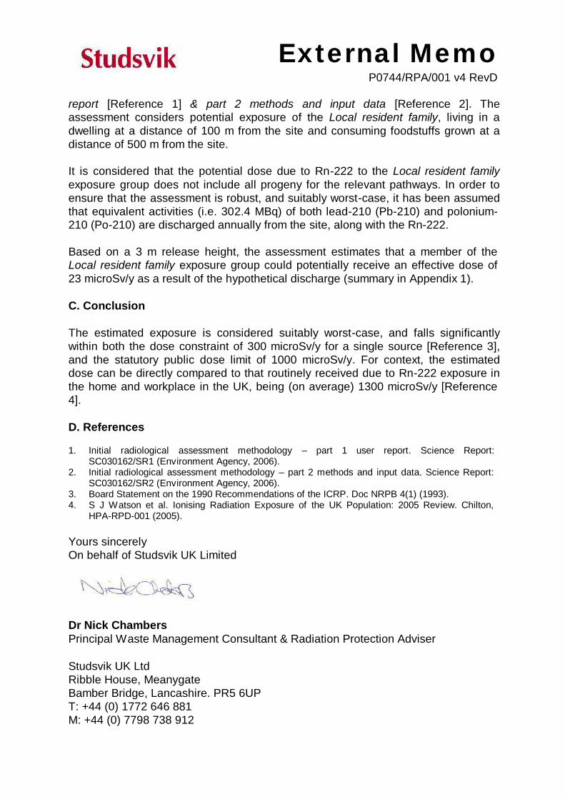
External MemoP0744/RPA/001 v4 RevD
report [Reference 1] & part 2 methods and input data [Reference 2]. Theassessment considers potential exposure of the Local resident family, living in adwelling at a distance of 100 m from the site and consuming foodstuffs grown at adistance of 500 m from the site.
It is considered that the potential dose due to Rn-222 to the Local resident familyexposure group does not include all progeny for the relevant pathways. In order toensure that the assessment is robust, and suitably worst-case, it has been assumedthat equivalent activities (i.e. 302.4 MBq) of both lead-210 (Pb-210) and polonium-210 (Po-210) are discharged annually from the site, along with the Rn-222.
Based on a 3 m release height, the assessment estimates that a member of theLocal resident family exposure group could potentially receive an effective dose of23 microSv/y as a result of the hypothetical discharge (summary in Appendix 1).
C. Conclusion
The estimated exposure is considered suitably worst-case, and falls significantlywithin both the dose constraint of 300 microSv/y for a single source [Reference 3],and the statutory public dose limit of 1000 microSv/y. For context, the estimateddose can be directly compared to that routinely received due to Rn-222 exposure inthe home and workplace in the UK, being (on average) 1300 microSv/y [Reference4].
D. References
1. Initial radiological assessment methodology – part 1 user report. Science Report:SC030162/SR1 (Environment Agency, 2006).
2. Initial radiological assessment methodology – part 2 methods and input data. Science Report:SC030162/SR2 (Environment Agency, 2006).
3. Board Statement on the 1990 Recommendations of the ICRP. Doc NRPB 4(1) (1993).4. S J Watson et al. Ionising Radiation Exposure of the UK Population: 2005 Review. Chilton,
HPA-RPD-001 (2005).
Yours sincerelyOn behalf of Studsvik UK Limited
Dr Nick ChambersPrincipal Waste Management Consultant & Radiation Protection Adviser
Studsvik UK LtdRibble House, MeanygateBamber Bridge, Lancashire. PR5 6UPT: +44 (0) 1772 646 881M: +44 (0) 7798 738 912

External MemoP0744/RPA/001 v4 RevD
F: +44 (0) 1772 646 899www.studsvik.com
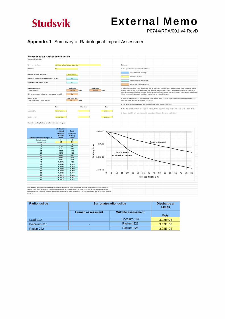
External MemoP0744/RPA/001 v4 RevD
Sca
ling
fact
or
Appendix 1 Summary of Radiological Impact Assessment
Releases to air - Assessment detailsVersion 4.0 De c 2011
Nam e of pre mises KMA User Defined Release Height 3 m Guidance
Reference N/A 1. The spreadsheet is colour coded as follows:
Row and column headingsEffective Re leas e Height / m User defined
Data entry by userInhalation & external exposure scaling factor 0.6
Data provided in spreadsheetFood expos ur e scaling factor 0.9
Results and interim calculations
Populat ion groups Total dos e Food Dos e 2. Asassessment Details - Enter the relevant data on this sheet. Enter dispersion scaling factors to take account of releaseheight or select the nearest height from the drop down list. Separate scaling factors should be entered for the inhalation &external exposure and the food exposure. Scaling factors for different release heights are show n in the figure or table below .Where no release height data is available a scaling factor of 1 should be used.
Local habitants 2.3E+01 Sv/y 5.9E+00 Sv/y
FSA consultation require d for non-nuclear permit? No
Wildlife Group Total dos e rate 3. Enter the limits for each radionuclide on the sheet 'Release to air'. You may need to select surrogate radionuclides or use the other alpha and other beta gamma categories.Terrestrial wildlife - Worst affected 6.5E+00 Gy/h
4. The results by each radionuclide are dis played on the sheet 'Summary total dose'.
Nam e Signature Date5. The dose contribution from each exposure pathway for this population group are shown in sheet 'Local habitant dose'.
Assessed by Nic k Chambers 13.05.156. Doses to wildlife from each radionuclide released are show n in 'Terrestrial wildlife dose'
Re vie w ed by Victoria Lilley 13.05.15
Dispersion scaling factors for different re leas e heights a
Effective Release Height / m
Inhalation &external
exposurescalingfactor
Foodexposurescalingfactor
1.0E+00
Food exposure1.0E-01
Inhalation &external exposure
1.0E-02
1.0E-030 5 10 15 20 25 30 35 40 45 50 55 60 65 70 75 80
Release height / m
De fault value s 1 1Us er de fine d 0.6 0.9
0 1 15 0.46 0.80
10 0.21 0.6515 0.091 0.4620 0.040 0.3325 0.023 0.2530 0.014 0.1935 0.010 0.1540 0.0071 0.1245 0.0056 0.09550 0.0043 0.07555 0.0034 0.06060 0.0029 0.05065 0.0023 0.04070 0.0019 0.03375 0.0015 0.02780 0.0013 0.023
a The dos e per unit release data for inhalation and external exposure in the spreadsheet has been assessed assuming a dispersionfactor of 7 10-5 Bq/m3 per Bq/s for a ground-level release and an exposure distance of 100 m. The dos e per unit release data for foodexposure has been assessed assuming a dispersion factor of 4 10 -6 Bq/m3 per Bq/s for a ground-level release and an exposure distanceof 500 m.
Radionuclide Surrogate radionuclide Discharge atLimits
Human assessment Wildlife assessmentBq/y
Lead-210 - Caesium-137 3.02E+08Polonium-210 - Radium-226 3.02E+08Radon-222 - Radium-226 3.02E+08

KM8 Hydraulic Fracturing Operations Waste Management Plan
Uncontrolled if printed KM8 WMP/Rev5/13-06-2017 Page 88
APPENDIX 8 – AIR QUALITY IMPACT ASSESSMENT

KM8 Hydraulic Fracturing Operations Waste Management Plan
Uncontrolled if printed KM8 WMP/Rev5/13-06-2017 Page 89
**This page has been intentionally left blank**
Third Energy UK Gas Limited
Air quality impact assessment of operations at the
Kirby Misperton A wellsite
Report 150332
Date 17 September 2015
Revision 10
Report No.150332 Page 1 of 41
Revision 10
17 September 2015
AIR QUALITY IMPACT ASSESSMENT OF OPERATIONS AT THE KIRBY MISPERTON A WELLSITE THIRD ENERGY UK GAS LIMITED
Report prepared for
Third Energy UK Gas Limited
Knapton Generating station
East Knapton
Malton
North Yorkshire
YO17 8JF
Report prepared by
Environmental Scientifics Group Limited Unit D
Bankside Trade Park
Cirencester
GL7 1YT
Author Dr N Ford
Report No.150332 Page 2 of 41
Revision 10
Third Energy UK Gas Limited
Kirby Misperton
ISSUE HISTORY
Revision Date Approved
150332,0 2 April 2015 N Ford
First issue
150332,1 7 April 2015 N Ford
Minor amendments to text following client review.
150332,2 10 April 2015 N Ford
Minor amendments to text following further client review.
150332,3 17 April 2015 N Ford
Addition of releases from site vehicle movements to air quality impact and greenhouse gas release inventory (section 4). Addition of recent results of baseline air quality monitoring (section 2.4).
150332,4 7 May 2015 N Ford
Amendements to vehicle movement schedule.
150332,5 15 May 2015 N Ford
Clarification of comments on the air quality impact of nitrogen dioxide at residential locations on pages 23 and 24.
150332,6 12 June 2015 N Ford
Amendments to account for the expansion of the Caravan Park and the addition of specific comments considering air quality impact at the Caravan site and the Flamingo Land Theme Park locations (sections 3 and 4, Annex A).
150332,7 29 June 2015 N Ford
Amendments to the vehicle movement schedule and duration of operating phases (Section 3) with corresponding revisions to the air quality assessment and greenhouse gas inventory (Section 4).
150332,8 30 June 2015 N Ford
Amendments to the vehicle movement schedule and extension of production phase from 1 to 9 years (Section 3) with corresponding revisions to the air quality assessment and greenhouse gas inventory (Section 4).
150332,9 29 July 2015 N Ford
Amendments following issue of Schedule 5 notice. Table 3.10 revised and inclusion of consideration of benzene in assessment of fugitive releases (sections 3.6 and 4.4).
150332,10 17 September 2015 N Ford
Amendments to section 2.4 to update details of recent baseline air quality monitoring.
Report No.150332 Page 3 of 41
Revision 10
Third Energy UK Gas Limited
Kirby Misperton
CONTENTS
Page No. COVER 1 ISSUE HISTORY 2 CONTENTS 3 0 SUMMARY 4 1 INTRODUCTION 5 1.1 Scope of study 5 1.2 General approach 5 1.3 Structure of report 5 2 POLICY CONTEXT AND ASSESSMENT CRITERIA 6 2.1 Context of assessment 6 2.2 Pollutants from well operations 6 2.3 Air quality standards 7 2.4 Background air quality in Kirby Misperton 8 3 MODELLING METHODOLOGY 10 3.1 Assessment area 10 3.2 Buildings 11 3.3 Meteorology 11 3.4 Terrain 13 3.5 Pollutant releases from point sources 14 3.6 Pollutant releases from fugitive releases 18 3.7 Nitrogen and acid deposition 20 3.8 Modelling scenarios 20 4 MODELLING RESULTS 21 4.1 Impact of releases around the site boundary 21 4.2 Impact of releases at the nearest residential locations 21 4.3 Impact of process releases at sensitive nature conservation
sites 26
4.4 Impact of fugitive releases 28 4.5 Releases of greenhouse gases 28 5 CONCLUSIONS 31 6 REFERENCES 32 Annex A Dispersion model contour plots 33 Annex B Modelling files 41
Report No.150332 Page 4 of 41
Revision 10
Third Energy UK Gas Limited
Kirby Misperton
0 SUMMARY
A dispersion modelling assessment using the ADMS 5 model was employed to predict the impact on local air quality of discharges of important pollutants from well operations at the Kirby Misperton A (KMA) wellsite. All operating phases associated with the well workover, fracturing, subsequent clean up and demobilisation prior to production were considered with emphasis on releases from temporary operations equipment, largely stationary diesel engines, and fugitive emissions from the natural gas transmission system. The greenhouse gas inventory for the operation was also assessed. Process contributions from engine releases to ground level concentrations of nitrogen dioxide and PM10 are expected to exceed short term air quality standards at the site boundary based on model predictions, although the extent of any exceedence is not clear due to the influence of temporary structures on the dispersion of low level engine exhaust releases. At the nearest locations of permanent human habitation process contributions to ground level concentrations of carbon monoxide, sulphur dioxide, volatile organic compounds and PM10 are not considered to be likely to have any significant impact on air quality. Process contributions of nitrogen dioxide are more significant, although it is concluded that these are unlikely to pose a substantial threat to the continued attainment of air quality standards. At the closest statutory designated nature conservation sites process contributions to ground level concentrations of sulphur dioxide and nitrogen dioxide are mostly below the level of significance and do not pose any substantial risk to attainment of the critical levels. Nutrient nitrogen and acid deposition associated with the process contributions at these locations are not considered to be significant in relation to corresponding critical loads. Natural gas produced from the KMA wellsite is transported via pipeline to the nearby Knapton Generating Station. Fugitive releases of natural gas are expected from the on site gas transmission system. Based on leakage rates assessed by Third Energy the impact on local air quality of fugitive natural gas releases was assessed. The maximum process contribution to ground level concentrations of methane, ethane , propane and higher hydrocarbons (expressed as benzene) was predicted to be equivalent to no more than 8% of the estimated long term environmental benchmark at the site boundary falling to below 1% of these levels at the nearest residential locations. The long term process contribution to ground level concentrations of these compounds during both pre production and production phases of well operations is not considered to be significant based on Environment Agency assessment criteria. The modelling assessment methodology and necessary assumptions provide a very conservative assessment of impact on air quality, particularly for nitrogen dioxide. The overall results and conclusions reached therefore incorporate a reasonable margin of comfort in spite of the inevitable uncertainty of such modelling studies. It is concluded that the well operations will not affect the attainment of air quality standards around the areas of permanent human habitation closest to the wellsite and will have negligible impact at local statutory designated conservation sites. Exceedences in short term air quality standards for some pollutants are likely on occasions around the site boundary. No exceedence in air quality standards is indicated for the locations of temporary habitation in the Caravan Park and nearby Flamingo Land Theme Park. Release of greenhouse gases during well operations are estimated to be around 1680 t CO2 equivalent, based on the expected duration of the defined operational phases. Due to the inherent uncertainty of this type of project the duration of some phases may exceed initial expectations and as such an estimate of 2602 tCO2 equivalent is provided as a maximum for the overall project.
Report No.150332 Page 5 of 41
Revision 10
Third Energy UK Gas Limited
Kirby Misperton
1 INTRODUCTION
Third Energy UK Gas Limited (Third Energy) placed a contract with Environmental Scientifics Group Limited (ESG) to undertake an assessment of the impact on local air quality of discharges of important pollutants from proposed operations at the Kirby Misperton A (KMA) wellsite, North Yorkshire.
1.1 Scope of study The purpose of this study is to assess the impact of releases from the proposed operations at the KMA wellsite on local air quality in the context of applicable air quality standards and accepted environmental benchmarks. It is necessary, as part of the application for a permit to operate, to demonstrate that the proposed development will not have a significant adverse impact on the ambient concentrations of important pollutants. The main issues to be addressed within this assessment are:
The impact on local air quality of releases of pollutants, both point source and fugitive, on local air quality
The estimated release of greenhouse gases during the period of operation
1.2 General approach The approach taken in this assessment comprised the following main stages:
Determine a suitable modelling tool for the assessment.
Collate available process design data for input to the model.
Determine pertinent point source release conditions over various phases of wellsite operation
Determine pertinent fugitive releases over the various phases of wellsite operation
Establish the influence of any proposed site buildings or structures on the dispersion of releases
Obtain information on local background concentrations of important pollutants.
Obtain 5 years’ recent meteorological data from a measurement station appropriate to the location.
Model the dispersion of releases of important pollutants from the wellsite operations to determine the process contribution to ambient concentrations over the local area with particular attention to locations of human exposure and statutory designated areas.
Assess the predicted process contributions and established background concentrations with reference to applicable air quality standards and environmental benchmarks to determine compliance.
Comment on the predicted impact of discharges of important pollutants on local air quality
Establish an inventory of greenhouse gas releases for the wellsite operations Further details of the approach taken and model input information are provided in the following sections.
1.3 Structure of the report This report provides an assessment of the impact of discharges from the proposed operations at the KMA wellsite on air quality in the vicinity and on releases of greenhouse gases. The approach to the assessment has been described above. The following sections provide a detailed commentary on the assessment and conclusions: Section 2 Air quality standards and assessment criteria Section 3 The model methodology employed and important input data Section 4 The results of the assessment Section 5 Conclusions of the assessment
Report No.150332 Page 6 of 41
Revision 10
Third Energy UK Gas Limited
Kirby Misperton
2 POLICY CONTEXT AND ASSESSMENT CRITERIA
The Kirby Misperton A wellsite is located 750m south west of Kirby Misperton village and around 1 km south east of the village of Little Barugh in the Ryedale District of North Yorkshire (see Figure 3.1). Kirby Misperton A is an existing wellsite and the Kirby Misperton 8 (KM8) well was most recently drilled by Third Energy in 2013 as part of an appraisal of gas reserves followed by subsequent production. This appraisal concluded that there is a resource of sandstone and shale in the deep Bowland section. The current operations proposed by Third Energy are for the hydraulic fracturing of five zones within the well and, if successful, flowing of the natural gas produced, by pipeline, to the Knapton Generating Station. This is intended to enable the appraisal of the potential of the reserve.
2.1 Context of assessment This operation will be under the control of both the minerals planning authority and the Environment Agency and will require planning permission and an environmental permit to operate. As part of the planning and permitting applications it is necessary to demonstrate the likely impact of operations on local ambient concentrations of important pollutants. It is in this context that the proposed operations are being examined to determine their additional contribution to the existing concentrations of important pollutants and therefore determine compliance with applicable air quality limit values and environmental benchmarks. Local Authorities are required to assess compliance with applicable air quality objectives. Where the objectives are unlikely to be met the Local Authority is required to declare an Air Quality Management Area (AQMA) and prepare proposals for remedial action to achieve the required objective. There are no declared AQMAs in the vicinity of the wellsite, in addition, there is no knowledge of any other intended developments locally that will significantly impact on existing air quality.
2.2 Pollutants from well operations The operations at Kirby Misperton do not involve any on site flaring of natural gas as the gas produced will be piped to the local Knapton Generating Station. There will however be releases of pollutants from two main sources:
Releases from the mobile plant used for the wellsite operations during the initial preparation, fracturing and well testing operations and subsequent site restoration.
Fugitive releases of natural gas from the initial fracturing process and during the subsequent production phase.
Substantial mobile plant is required for the intended operations. These will be predominately powered using stationary diesel engines. The main pollutants from the combustion of diesel fuel, are oxides of nitrogen (NOx), carbon monoxide (CO) and volatile organic compounds (VOCs). Oxides of nitrogen are generally considered to comprise of nitrogen monoxide (NO) and nitrogen dioxide (NO2). Emissions from combustion primarily consist of nitrogen monoxide, although reaction in the atmosphere results in conversion to nitrogen dioxide, which is the primary nitrogen oxide of interest with respect to ambient pollution. Carbon monoxide and volatile organic compounds are generally formed from incomplete combustion of fuel and their presence will therefore be related to efficiency of combustion. It is assumed that the diesel fuel used will meet current regulations and as such will have a sulphur content of 0.1% by mass or less. A worst case is assumed in this assessment with consideration of discharges of sulphur dioxide (SO2) consistent with the maximum allowable fuel sulphur content. Diesel combustion may also give rise to the release of fine particulate matter. In this assessment PM10
(particulate matter with an aerodynamic diameter below 10 µm) releases from the combustion of diesel have been considered. Air quality standards for England consider limit values for nitrogen dioxide, carbon monoxide, sulphur dioxide and PM10. The standards specified are in the form of concentrations and are determined to be
Report No.150332 Page 7 of 41
Revision 10
Third Energy UK Gas Limited
Kirby Misperton
levels below which effects are unlikely even in sensitive population groups or below which the risk to public health would be very small. There are no applicable standards for the general group of volatile organic compounds, although guidance
1 recommends comparison with the air quality standards for
benzene as a means of determining significance.
2.3 Air Quality Standards The UK’s air quality strategy is based on meeting obligations within the European Union (EU) Ambient Air Quality Directive (2008/50/EC, 21 May 2008)
2 and the Fourth Daughter Directive (relating to metals and
hydrocarbons). Table 2.1 summarises the applicable limit values for the pollutants considered in this assessment as at 2015. It may be seen that standards are generally provided on the basis of short term and long term means. The limit values are considered to apply where members of the public are likely to be regularly exposed over the monitoring period. For the longer averaging periods the standards are considered to apply around the frontage of premises such as residential properties, schools and hospitals. The shorter term limit value (1 hour or 1 day means) applies at these locations and other areas where exposure is likely to be of one hour or more on a regular basis. In some cases air quality standards (AQS) discuss standards (concentrations recorded over a specified time period which are considered to be acceptable in terms of current knowledge of the impact on health and the environment), objectives (target date by which the standard is expected to be met) and limit values (a legally binding time averaged limit which must not be exceeded). In the case of pollutants considered above the values specified are limit values which the UK is obliged to meet. In addition, the Environment Agency guidance (H1, Annex F
1) provides environmental assessment levels
(EALs) for the protection of human health which may also be employed to assess the significance of ambient pollutant concentrations. These are also summarised in Table 2.1. Where an AQS or EAL is not available, workplace exposure limits have been employed, together with the methodology in H1, Annex F
1, to provide a benchmark for this assessment.
Table 2.1 UK Air Quality Standards and Environmental Assessment Levels
Pollutant Basis Concentration
Air quality standards
Carbon monoxide (CO) running 8 hour mean 10 mg/m3
Nitrogen dioxide (NO2) 1 hour mean (99.79 percentile – 18 exceedences per year) 200 µg/m3
annual mean 40 µg/m3
Sulphur dioxide (SO2)
15 minute mean (99.9 percentile – 35 exceedences per year) 266 µg/m3
1 hour mean (99.72 percentile – 24 exceedences per year) 350 µg/m3
24 hour mean – 99.18 percentile – 3 exceedences per year) 125 µg/m3
PM10 24 hour mean (90.41 percentile- 35 exceedences per year) 50 µg/m
3
annual mean 40 µg/m3
Benzene annual mean 5 µg/m3
Environmental assessment levels
Carbon monoxide (CO) Short term 30000 µg/m3
Environmental assessment levels determined from workplace exposure limits
Methane Long term 7140 µg/m3
Ethane Long term 13420 µg/m3
Propane Long term 19680 µg/m3
Long term and short term EALs are assumed to apply to annual and hourly values respectively. Values determined from workplace exposure limits use the methodology specified in H1, Annex F
1 and the
workplace exposure values provided in the HSE’s EH40/20053 and OSHA’s PEL
4.
In addition to the standards associated with human health above, critical levels are specified
1 for sulphur
dioxide and nitrogen dioxide in relation to the protection of vegetation and ecosystems as shown in Table 2.2.
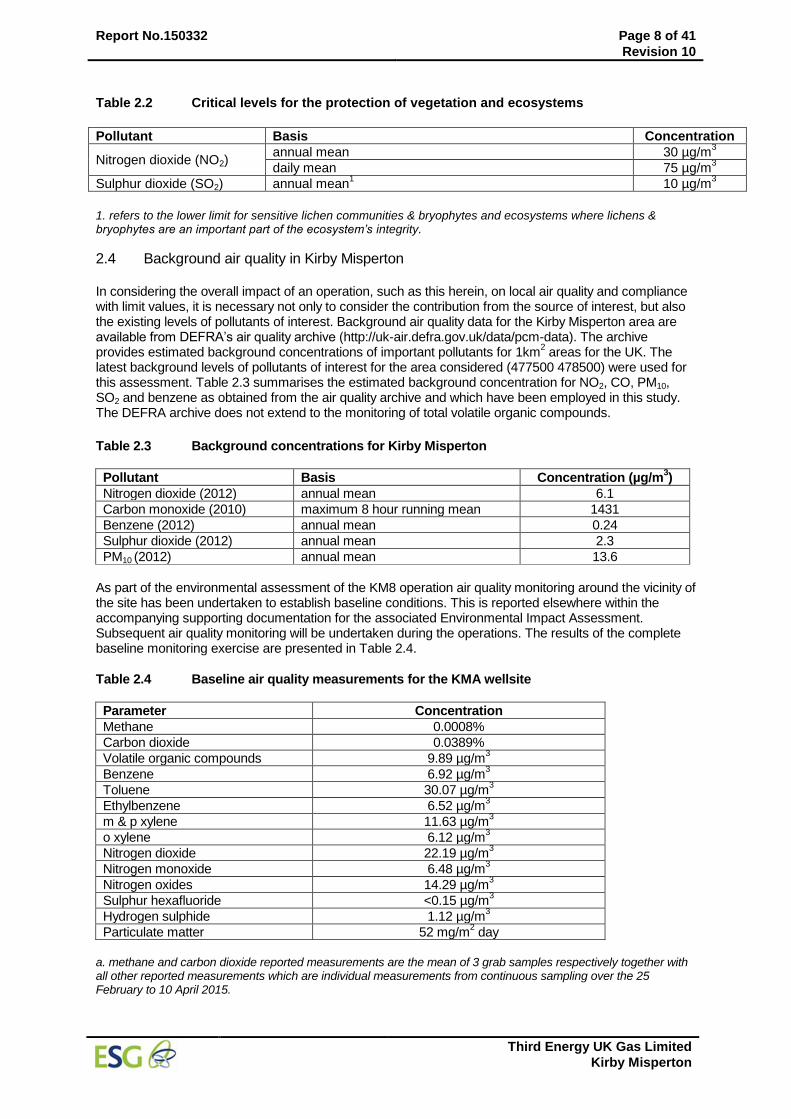
Report No.150332 Page 8 of 41
Revision 10
Third Energy UK Gas Limited
Kirby Misperton
Table 2.2 Critical levels for the protection of vegetation and ecosystems
Pollutant Basis Concentration
Nitrogen dioxide (NO2) annual mean 30 µg/m
3
daily mean 75 µg/m3
Sulphur dioxide (SO2) annual mean1 10 µg/m
3
1. refers to the lower limit for sensitive lichen communities & bryophytes and ecosystems where lichens & bryophytes are an important part of the ecosystem’s integrity.
2.4 Background air quality in Kirby Misperton In considering the overall impact of an operation, such as this herein, on local air quality and compliance with limit values, it is necessary not only to consider the contribution from the source of interest, but also the existing levels of pollutants of interest. Background air quality data for the Kirby Misperton area are available from DEFRA’s air quality archive (http://uk-air.defra.gov.uk/data/pcm-data). The archive provides estimated background concentrations of important pollutants for 1km
2 areas for the UK. The
latest background levels of pollutants of interest for the area considered (477500 478500) were used for this assessment. Table 2.3 summarises the estimated background concentration for NO2, CO, PM10, SO2 and benzene as obtained from the air quality archive and which have been employed in this study. The DEFRA archive does not extend to the monitoring of total volatile organic compounds.
Table 2.3 Background concentrations for Kirby Misperton
Pollutant Basis Concentration (µg/m3)
Nitrogen dioxide (2012) annual mean 6.1
Carbon monoxide (2010) maximum 8 hour running mean 1431
Benzene (2012) annual mean 0.24
Sulphur dioxide (2012) annual mean 2.3
PM10 (2012) annual mean 13.6
As part of the environmental assessment of the KM8 operation air quality monitoring around the vicinity of the site has been undertaken to establish baseline conditions. This is reported elsewhere within the accompanying supporting documentation for the associated Environmental Impact Assessment. Subsequent air quality monitoring will be undertaken during the operations. The results of the complete baseline monitoring exercise are presented in Table 2.4.
Table 2.4 Baseline air quality measurements for the KMA wellsite
Parameter Concentration
Methane 0.0008%
Carbon dioxide 0.0389%
Volatile organic compounds 9.89 µg/m3
Benzene 6.92 µg/m3
Toluene 30.07 µg/m3
Ethylbenzene 6.52 µg/m3
m & p xylene 11.63 µg/m3
o xylene 6.12 µg/m3
Nitrogen dioxide 22.19 µg/m3
Nitrogen monoxide 6.48 µg/m3
Nitrogen oxides 14.29 µg/m3
Sulphur hexafluoride <0.15 µg/m3
Hydrogen sulphide 1.12 µg/m3
Particulate matter 52 mg/m2 day
a. methane and carbon dioxide reported measurements are the mean of 3 grab samples respectively together with all other reported measurements which are individual measurements from continuous sampling over the 25 February to 10 April 2015.
Report No.150332 Page 9 of 41
Revision 10
Third Energy UK Gas Limited
Kirby Misperton
The concentration of methane of 0.0008% is consistent with the monitoring point located offsite, suggesting that the area in general is higher than the UK general background. However it should also be noted that maintenance on the existing production plant within the KM1 wellsite was being undertaken during periods of monitoring which could attribute to slightly elevated methane levels. A total of three (3) sampling rounds were undertaken to establish a baseline figure for ambient air quality. These were taken every two (2) weeks between the 25 February 2015 and 10 April 2015. Once collected, the samples were analysed by ESG within a couple of days. Four monitoring locations were selected in order to give a wide coverage of the main site. A ‘clean’ sample point was chosen and a monitoring stand positioned outside the South West corner of the KMA wellsite, 20m south along the access track. The position was chosen to give a baseline for all of the required parameters. Three (3) further monitoring locations identified around KMA wellsite. The first location, in the North East corner of the wellsite, was chosen, taking into account prevailing wind direct, site elevation and future positioning of equipment. The second location, in the North West corner of the wellsite, was chosen following the considerations as the first. The third monitoring location, in the South East corner of the wellsite, was chosen to provide a full perimeter monitoring suite and the prevailing wind direction. The ‘clean sample’ placed outside the South West corner of the wellsite would give the make of any particles coming onto the wellsite. This would then be deducted from other samples to give a true sample of particulates generated from the works being carried out within the wellsite. For clarity, any parameters that will be monitored by grab sampling techniques will be done so at the four (4) monitoring locations to ensure consistency amongst all of the monitoring rounds. It is important to state that the locations proposed are the same locations that have been used to establish the baseline condition. An additional grab sample will also be taken by the ESG engineers for methane whilst attending site. The additional monitoring location shall be variable and will be determined on the day by the wind speed and direction. A minimum distance from the methane emission sources will be 5m on a still/calm day, with a maximum of 20 meters on a windy day. The location will also be dependent on any ATEX zones that are established at the KMA wellsite. Although proposed monitoring plan would only provide for one (1) clear downwind sampling location (with the addition of the variable methane sampling), Third Energy have been advised by ESG that the proposed locations are sufficient. When considering the combination of estimated process contributions and background concentrations it should be noted that background concentrations are generally available as annual mean values and as such simple addition when considering short term air quality standards may not be appropriate. Guidance from the Environment Agency
5 suggests a simplified method for combining
estimated process contributions and background concentrations. For comparison with long term standards the overall concentration is the sum of the process contribution (annual mean) and background concentration (annual mean). For comparison with short term standards the Environment Agency suggest the sum of the process contribution (hourly or daily mean) and twice the background concentration (annual mean). This methodology has been employed in this assessment. The Environment Agency’s guidance note H1
1 provides a methodology for assessing the impact and
determining the acceptability of emissions to atmosphere on ambient air quality. The contribution of the process (PC) to the ambient concentration of a given pollutant is considered insignificant if:
the long term PC is less than 1% of the long term environmental standard
the short term PC is less than 10% of the short term environmental standard
If the long term PC is greater than 1% of the environmental standard then the corresponding predicted environmental concentration (PEC, PC + background concentration) should be assessed. The ambient concentration of the pollutant is unlikely to have a significant effect if:
The long term PEC is less than 70% of the relevant long-term environmental standard
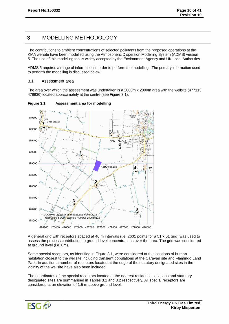
Report No.150332 Page 10 of 41
Revision 10
Third Energy UK Gas Limited
Kirby Misperton
3 MODELLING METHODOLOGY
The contributions to ambient concentrations of selected pollutants from the proposed operations at the KMA wellsite have been modelled using the Atmospheric Dispersion Modelling System (ADMS) version 5. The use of this modelling tool is widely accepted by the Environment Agency and UK Local Authorities. ADMS 5 requires a range of information in order to perform the modelling. The primary information used to perform the modelling is discussed below.
3.1 Assessment area The area over which the assessment was undertaken is a 2000m x 2000m area with the wellsite (477113 478936) located approximately at the centre (see Figure 3.1).
Figure 3.1 Assessment area for modelling
A general grid with receptors spaced at 40 m intervals (i.e. 2601 points for a 51 x 51 grid) was used to assess the process contribution to ground level concentrations over the area. The grid was considered at ground level (i.e. 0m). Some special receptors, as identified in Figure 3.1, were considered at the locations of human habitation closest to the wellsite including transient populations at the Caravan site and Flamingo Land Park. In addition a number of receptors located at the edge of the statutory designated sites in the vicinity of the wellsite have also been included. The coordinates of the special receptors located at the nearest residential locations and statutory designated sites are summarised in Tables 3.1 and 3.2 respectively. All special receptors are considered at an elevation of 1.5 m above ground level.
©Crown copyright and database rights 2015 Ordnance Survey Licence Number 100056116
Report No.150332 Page 11 of 41
Revision 10
Third Energy UK Gas Limited
Kirby Misperton
Table 3.1 Locations of residential receptors
Location (see Figure 3.1) Easting Northing
1 Alma Farm 476847 479139
2 Kirby-O-Carr 477115 478619
3 Tuiffit Manor 476728 478287
4 High Grange Farm 477802 478865
5 Glebe Farm 477371 479489
6 Caravan Park 477530 479274
7 Manor Farm 476196 479640
8 North west Farm 477830 478140
Table 3.2 Locations of statutory designated sites
Site Designation
a Position
b Easting Northing
Howardian Hills AONB 6.0 km S 476862 473113
Newbridge Quarry SSSI 7.2 km NE 479904 485282
River Derwent SSSI, SAC 6.4 km SE 482433 475800
Green Lane Pit SSSI 6.2 km NW 473227 483663
Cropton Bank SSSI 8.9 km NW 474491 487179
The Ings SSSI 4.0 km SW 475834 475286
Haugh & Gundale Slacks SSSI 9.5 km NE 479746 487712
Golden Hill Pit SSSI 5.9 km NW 472555 482596
Ellerburn Bank SSSI 10 km NE 485001 484690
a. SSSI (Site of special scientific interest), AONB (Area of outstanding natural beauty), SAC (Special area of conservation). b. Position is the edge of the site closest to the wellsite.
3.2 Buildings The presence of buildings close to a release point can have a significant impact on the dispersion of releases. The most significant impact can be the downwash of a plume around a building causing increased concentrations in the immediate area around the building. Buildings can also disturb the wind flow causing turbulent wake downwind which can also affect dispersion. It is normally considered that buildings within 5 times the height of release should be considered in any modelling. The temporary structures and buildings intended for the site are generally at a relatively low level of around 3-4 m, however the exhausts from the engines are generally of similar height and as such it is considered necessary to include some consideration of temporary structures within the modelling. A sound barrier consisting of ISO containers to a height of 8.7 m will be located close to the site boundary on the north, east and west side. ADMS 5 models buildings as either rectangular or circular structure. As shown in Figure 3.2 the structures which are considered to be significant in relation to dispersion from the various engine exhausts are estimated as rectangular blocks based on the site plan provided by Third Energy
6.This is a
necessary approximation given the number of individual blocks and their varying height. Subsequent sensitivity analyses undertaken indicated that the main impact of on-site buildings is on the dispersion and subsequent ground level concentrations around the site boundary. Consideration of buildings has insignificant impact on the predicted ground level pollutant concentrations beyond around 200 m of the site and no impact at the nearest locations of human habitation as summarised in Table 3.1.
3.3 Meteorology For this modelling assessment hourly sequential meteorological data from the nearest suitable meteorological station to the Kirby Misperton site was obtained. The data, provided by the UK Met Office, was from the Leconfield station and covered the 5-year period 2008 to 2012.
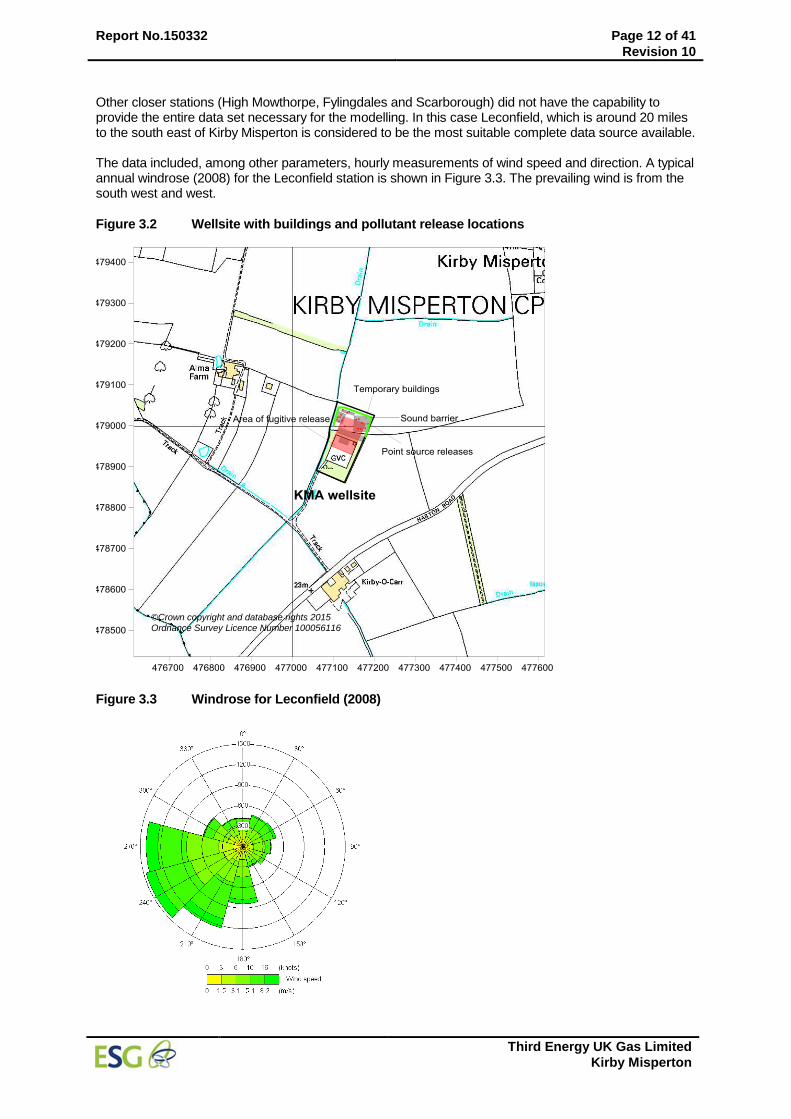
Report No.150332 Page 12 of 41
Revision 10
Third Energy UK Gas Limited
Kirby Misperton
Other closer stations (High Mowthorpe, Fylingdales and Scarborough) did not have the capability to provide the entire data set necessary for the modelling. In this case Leconfield, which is around 20 miles to the south east of Kirby Misperton is considered to be the most suitable complete data source available. The data included, among other parameters, hourly measurements of wind speed and direction. A typical annual windrose (2008) for the Leconfield station is shown in Figure 3.3. The prevailing wind is from the south west and west.
Figure 3.2 Wellsite with buildings and pollutant release locations
Figure 3.3 Windrose for Leconfield (2008)
©Crown copyright and database rights 2015 Ordnance Survey Licence Number 100056116
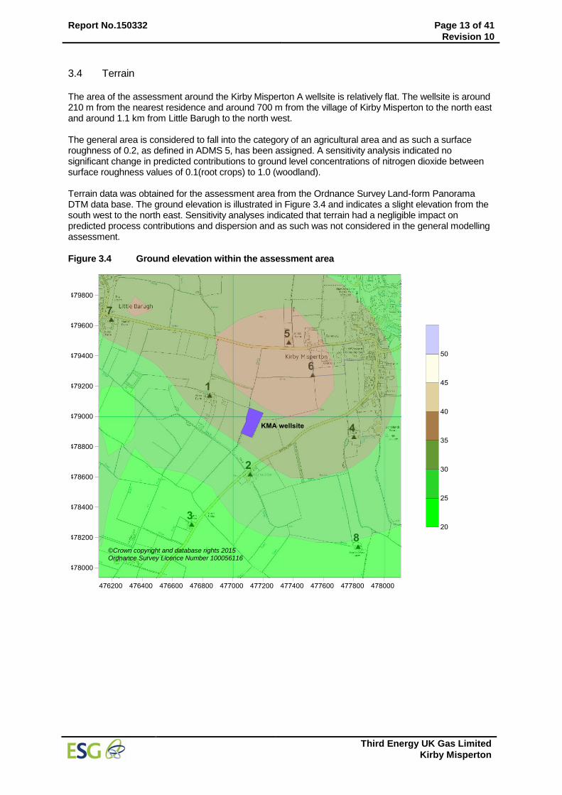
Report No.150332 Page 13 of 41
Revision 10
Third Energy UK Gas Limited
Kirby Misperton
3.4 Terrain The area of the assessment around the Kirby Misperton A wellsite is relatively flat. The wellsite is around 210 m from the nearest residence and around 700 m from the village of Kirby Misperton to the north east and around 1.1 km from Little Barugh to the north west. The general area is considered to fall into the category of an agricultural area and as such a surface roughness of 0.2, as defined in ADMS 5, has been assigned. A sensitivity analysis indicated no significant change in predicted contributions to ground level concentrations of nitrogen dioxide between surface roughness values of 0.1(root crops) to 1.0 (woodland). Terrain data was obtained for the assessment area from the Ordnance Survey Land-form Panorama DTM data base. The ground elevation is illustrated in Figure 3.4 and indicates a slight elevation from the south west to the north east. Sensitivity analyses indicated that terrain had a negligible impact on predicted process contributions and dispersion and as such was not considered in the general modelling assessment.
Figure 3.4 Ground elevation within the assessment area
©Crown copyright and database rights 2015 Ordnance Survey Licence Number 100056116
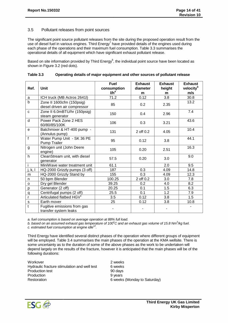
Report No.150332 Page 14 of 41
Revision 10
Third Energy UK Gas Limited
Kirby Misperton
3.5 Pollutant releases from point sources
The significant point source pollutant releases from the site during the proposed operation result from the use of diesel fuel in various engines. Third Energy
7 have provided details of the engines used during
each phase of the operations and their maximum fuel consumption. Table 3.3 summarises the operational details of all equipment which have significant exhaust pollutant release. Based on site information provided by Third Energy
6, the individual point source have been located as
shown in Figure 3.2 (red dots).
Table 3.3 Operating details of major equipment and other sources of pollutant release
Ref. Unit
Fuel
consumption
l/ha
Exhaust
diameter
m
Exhaust
height
m
Exhaust
velocityb
m/s
a ICH truck (MB Actros 2641l) 71.2 0.12 3.8 30.8
b Zone II 1600cfm (150psig) diesel driven air compressor
85 0.2 2.35 13.2
c Zone II 6.0mBTU/hr (150psig) steam generator
150 0.4 2.96 7.4
d Power Pack Zone 2 HES 60/80/85/100K
106 0.3 3.21 43.6
e Batchmixer & HT-400 pump - (Annulus pump)
131 2 off 0.2 4.05 10.4
f Water Pump Unit - SK 36 PE Pump Trailer
95 0.12 3.8 44.1
g Nitrogen unit (John Deere engine)
105 0.20 2.51 16.3
h CleanStream unit, with diesel generator
57.5 0.20 3.0 9.0
i MiniWave water treatment unit 61.1 2.0 9.5
j, k, l HQ-2000 Grizzly pumps (3 off) 187 0.3 4.09 14.8
m HQ-2000 Grizzly Stand by 155 0.3 4.09 12.3
n 50 bpm Blender 100.25 2 off 0.2 3.0 7.8
o Dry gel Blender 39.25 0.2 4.0 8.2
p Generator (2 off) 20.25 0.1 1.5 6.3
q Centrifugal pumps (2 off) 25.5 0.1 1.2 7.9
r Articulated flatbed HGVc 3.5 0.12 3.8 1.5
s Earth mover 25 0.12 3.8 10.8
t Fugitive emissions from gas transfer system leaks
- - - -
a. fuel consumption is based on average operation at 88% full load. b. based on an assumed exhaust gas temperature of 100
oC and an exhaust gas volume of 15.8 Nm
3/kg fuel.
c. estimated fuel consumption at engine idle12
.
Third Energy have identified several distinct phases of the operation where different groups of equipment will be employed. Table 3.4 summarises the main phases of the operation at the KMA wellsite. There is some uncertainty as to the duration of some of the above phases as the work to be undertaken will depend largely on the results of the fracture, however it is anticipated that the main phases will be of the following durations: Workover 2 weeks Hydraulic fracture stimulation and well test 6 weeks Production test 90 days Production 9 years Restoration 6 weeks (Monday to Saturday)
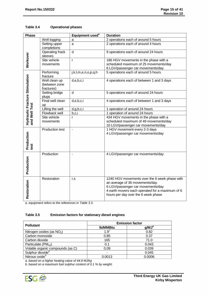
Report No.150332 Page 15 of 41
Revision 10
Third Energy UK Gas Limited
Kirby Misperton
Table 3.4 Operational phases
Phase Equipment useda Duration
Wo
rko
ver
Well logging a 2 operations each of around 5 hours
Setting upper completions
a 2 operations each of around 4 hours
Operating frack sleeves
d 9 operations each of around 24 hours
Site vehicle movements
r 186 HGV movements in the phase with a scheduled maximum of 25 movements/day 6 LGV/passenger car movements/day
Hyd
rau
lic F
ractu
re S
tim
ula
tio
n
an
d W
ell T
es
t
Performing fracture
j,k,l,m,e,n,o,p,q,h 5 operations each of around 5 hours
Well clean up (between zone fractures)
d,e,b,c,i 4 operations each of between 1 and 3 days
Setting bridge plugs
d 5 operations each of around 24 hours
Final well clean up
d,e,b,c,i 4 operations each of between 1 and 3 days
Lifting the well d,g,b,c,i 1 operation of around 24 hours
Flowback well b,c,i 1 operation of around 24 hours
Site vehicle movements
r 434 HGV movements in the phase with a scheduled maximum of 49 movements/day 10 LGV/passenger car movements/day
Pro
du
cti
on
test
Production test - 1 HGV movement every 2-3 days 4 LGV/passenger car movements/day
Pro
du
cti
on
Production - 4 LGV/passenger car movements/day
Resto
rati
on
Restoration r,s 1240 HGV movements over the 6 week phase with an average of 36 movements/day. 6 LGV/passenger car movements/day 4 earth movers each operated for a maximum of 6 hours per day over the 6 week phase
a. equipment refers to the references in Table 3.3.
Table 3.5 Emission factors for stationary diesel engines
Pollutant Emission factor
lb/MMBtu g/MJa
Nitrogen oxides (as NO2) 1.9c 0.82
Carbon monoxide 0.85 0.37
Carbon dioxide 165 71.0
Particulate (PM10) 0.1 0.043
Volatile organic compounds (as C) 0.09 0.039
Sulphur dioxideb - 0.045
Nitrous oxided 0.0013 0.0006
a. based on a higher heating value of 44.8 MJ/kg b. based on a maximum fuel sulphur content of 0.1 % by weight.
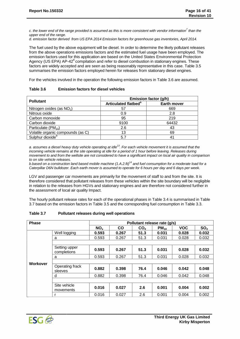
Report No.150332 Page 16 of 41
Revision 10
Third Energy UK Gas Limited
Kirby Misperton
c. the lower end of the range provided is assumed as this is more consistent with vendor information7 than the
upper end of the range. d. emission factor derived from US EPA 2014 Emission factors for greenhouse gas inventories, April 2014.
The fuel used by the above equipment will be diesel. In order to determine the likely pollutant releases from the above operations emissions factors and the estimated fuel usage have been employed. The emission factors used for this application are based on the United States Environmental Protection Agency (US EPA) AP-42
8 compilation and refer to diesel combustion in stationary engines. These
factors are widely accepted and are seen as being reasonably representative in this case. Table 3.5 summarises the emission factors employed herein for releases from stationary diesel engines. For the vehicles involved in the operation the following emission factors in Table 3.6 are assumed.
Table 3.6 Emission factors for diesel vehicles
Pollutant Emission factor (g/h)
Articulated flatbeda Earth mover
Nitrogen oxides (as NO2) 57 669
Nitrous oxide 0.9 2.8
Carbon monoxide 95 219
Carbon dioxide 9100 64432
Particulate (PM10) 2.6 43
Volatile organic compounds (as C) 13 69
Sulphur dioxideb 5.7 41
a. assumes a diesel heavy duty vehicle operating at idle
13. For each vehicle movement it is assumed that the
incoming vehicle remains at the site operating at idle for a period of 1 hour before leaving. Releases during movement to and from the wellsite are not considered to have a significant impact on local air quality in comparison to on site vehicle releases. b.based on a construction land based mobile machine (1.A.2.fii)
14 and fuel consumption for a moderate load for a
Caterpillar D6N bulldozer. Each earth mover is assumed to operate for 6 hours per day and 6 days per week.
LGV and passenger car movements are primarily for the movement of staff to and from the site. It is therefore considered that pollutant releases from these vehicles within the site boundary will be negligible in relation to the releases from HGVs and stationary engines and are therefore not considered further in the assessment of local air quality Impact. The hourly pollutant release rates for each of the operational phases in Table 3.4 is summarised in Table 3.7 based on the emission factors in Table 3.5 and the corresponding fuel consumption in Table 3.3.
Table 3.7 Pollutant releases during well operations
Phase Pollutant release rate (g/s)
NOx CO CO2 PM10 VOC SO2
Workover
Well logging 0.593 0.267 51.3 0.031 0.028 0.032
a 0.593 0.267 51.3 0.031 0.028 0.032
Setting upper completions
0.593 0.267 51.3 0.031 0.028 0.032
a 0.593 0.267 51.3 0.031 0.028 0.032
Operating frack sleeves
0.882 0.398 76.4 0.046 0.042 0.048
d 0.882 0.398 76.4 0.046 0.042 0.048
Site vehicle movements
0.016 0.027 2.6 0.001 0.004 0.002
r 0.016 0.027 2.6 0.001 0.004 0.002
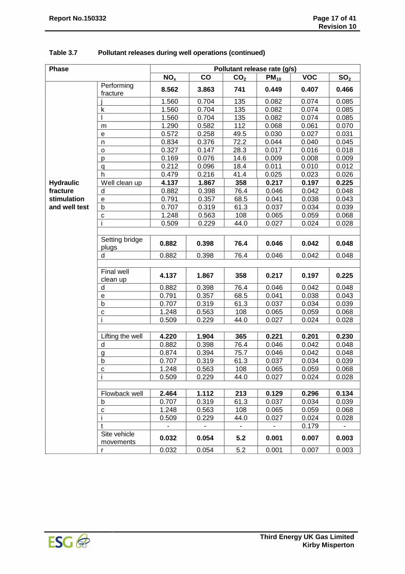
Report No.150332 Page 17 of 41
Revision 10
Third Energy UK Gas Limited
Kirby Misperton
Table 3.7 Pollutant releases during well operations (continued)
Phase Pollutant release rate (g/s)
NOx CO CO2 PM10 VOC SO2
Performing fracture
8.562 3.863 741 0.449 0.407 0.466
j 1.560 0.704 135 0.082 0.074 0.085
k 1.560 0.704 135 0.082 0.074 0.085
l 1.560 0.704 135 0.082 0.074 0.085
m 1.290 0.582 112 0.068 0.061 0.070
e 0.572 0.258 49.5 0.030 0.027 0.031
n 0.834 0.376 72.2 0.044 0.040 0.045
o 0.327 0.147 28.3 0.017 0.016 0.018
p 0.169 0.076 14.6 0.009 0.008 0.009
q 0.212 0.096 18.4 0.011 0.010 0.012
h 0.479 0.216 41.4 0.025 0.023 0.026
Hydraulic
fracture
stimulation
and well test
Well clean up 4.137 1.867 358 0.217 0.197 0.225
d 0.882 0.398 76.4 0.046 0.042 0.048
e 0.791 0.357 68.5 0.041 0.038 0.043
b 0.707 0.319 61.3 0.037 0.034 0.039
c 1.248 0.563 108 0.065 0.059 0.068
i 0.509 0.229 44.0 0.027 0.024 0.028
Setting bridge plugs
0.882 0.398 76.4 0.046 0.042 0.048
d 0.882 0.398 76.4 0.046 0.042 0.048
Final well clean up
4.137 1.867 358 0.217 0.197 0.225
d 0.882 0.398 76.4 0.046 0.042 0.048
e 0.791 0.357 68.5 0.041 0.038 0.043
b 0.707 0.319 61.3 0.037 0.034 0.039
c 1.248 0.563 108 0.065 0.059 0.068
i 0.509 0.229 44.0 0.027 0.024 0.028
Lifting the well 4.220 1.904 365 0.221 0.201 0.230
d 0.882 0.398 76.4 0.046 0.042 0.048
g 0.874 0.394 75.7 0.046 0.042 0.048
b 0.707 0.319 61.3 0.037 0.034 0.039
c 1.248 0.563 108 0.065 0.059 0.068
i 0.509 0.229 44.0 0.027 0.024 0.028
Flowback well 2.464 1.112 213 0.129 0.296 0.134
b 0.707 0.319 61.3 0.037 0.034 0.039
c 1.248 0.563 108 0.065 0.059 0.068
i 0.509 0.229 44.0 0.027 0.024 0.028
t - - - - 0.179 -
Site vehicle movements
0.032 0.054 5.2 0.001 0.007 0.003
r 0.032 0.054 5.2 0.001 0.007 0.003
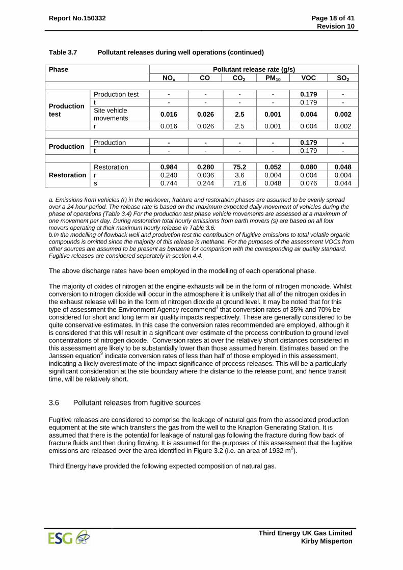
Report No.150332 Page 18 of 41
Revision 10
Third Energy UK Gas Limited
Kirby Misperton
Table 3.7 Pollutant releases during well operations (continued)
Phase Pollutant release rate (g/s)
NOx CO CO2 PM10 VOC SO2
Production
test
Production test - - - - 0.179 -
t - - - - 0.179 -
Site vehicle movements
0.016 0.026 2.5 0.001 0.004 0.002
r 0.016 0.026 2.5 0.001 0.004 0.002
Production Production - - - - 0.179 -
t - - - - 0.179 -
Restoration
Restoration 0.984 0.280 75.2 0.052 0.080 0.048
r 0.240 0.036 3.6 0.004 0.004 0.004
s 0.744 0.244 71.6 0.048 0.076 0.044
a. Emissions from vehicles (r) in the workover, fracture and restoration phases are assumed to be evenly spread over a 24 hour period. The release rate is based on the maximum expected daily movement of vehicles during the phase of operations (Table 3.4) For the production test phase vehicle movements are assessed at a maximum of one movement per day. During restoration total hourly emissions from earth movers (s) are based on all four movers operating at their maximum hourly release in Table 3.6. b.In the modelling of flowback well and production test the contribution of fugitive emissions to total volatile organic compounds is omitted since the majority of this release is methane. For the purposes of the assessment VOCs from other sources are assumed to be present as benzene for comparison with the corresponding air quality standard. Fugitive releases are considered separately in section 4.4.
The above discharge rates have been employed in the modelling of each operational phase. The majority of oxides of nitrogen at the engine exhausts will be in the form of nitrogen monoxide. Whilst conversion to nitrogen dioxide will occur in the atmosphere it is unlikely that all of the nitrogen oxides in the exhaust release will be in the form of nitrogen dioxide at ground level. It may be noted that for this type of assessment the Environment Agency recommend
1 that conversion rates of 35% and 70% be
considered for short and long term air quality impacts respectively. These are generally considered to be quite conservative estimates. In this case the conversion rates recommended are employed, although it is considered that this will result in a significant over estimate of the process contribution to ground level concentrations of nitrogen dioxide. Conversion rates at over the relatively short distances considered in this assessment are likely to be substantially lower than those assumed herein. Estimates based on the Janssen equation
9 indicate conversion rates of less than half of those employed in this assessment,
indicating a likely overestimate of the impact significance of process releases. This will be a particularly significant consideration at the site boundary where the distance to the release point, and hence transit time, will be relatively short.
3.6 Pollutant releases from fugitive sources
Fugitive releases are considered to comprise the leakage of natural gas from the associated production equipment at the site which transfers the gas from the well to the Knapton Generating Station. It is assumed that there is the potential for leakage of natural gas following the fracture during flow back of fracture fluids and then during flowing. It is assumed for the purposes of this assessment that the fugitive emissions are released over the area identified in Figure 3.2 (i.e. an area of 1932 m
2).
Third Energy have provided the following expected composition of natural gas.
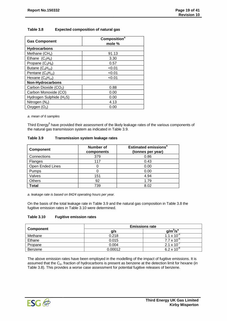
Report No.150332 Page 19 of 41
Revision 10
Third Energy UK Gas Limited
Kirby Misperton
Table 3.8 Expected composition of natural gas
Gas Component Composition
a
mole %
Hydrocarbons
Methane (CH4) 91.13
Ethane (C2H6) 3.30
Propane (C3H8) 0.57
Butane (C4H10) <0.01
Pentane (C5H12) <0.01
Hexane (C6H14) <0.01
Non-Hydrocarbons
Carbon Dioxide (CO2) 0.88
Carbon Monoxide (CO) 0.00
Hydrogen Sulphide (H2S) 0.00
Nitrogen (N2) 4.13
Oxygen (O2) 0.00
a. mean of 6 samples
Third Energy
6 have provided their assessment of the likely leakage rates of the various components of
the natural gas transmission system as indicated in Table 3.9.
Table 3.9 Transmission system leakage rates
Component Number of
components
Estimated emissionsa
(tonnes per year)
Connections 379 0.86
Flanges 117 0.43
Open Ended Lines 0 0.00
Pumps 0 0.00
Valves 151 4.94
Others 92 1.79
Total 739 8.02
a. leakage rate is based on 8424 operating hours per year.
On the basis of the total leakage rate in Table 3.9 and the natural gas composition in Table 3.8 the fugitive emission rates in Table 3.10 were determined.
Table 3.10 Fugitive emission rates
Component Emissions rate
g/s g/m2/s
a
Methane 0.218 1.1 x 10⁻⁴
Ethane 0.015 7.7 x 10⁻⁶
Propane 0.004 2.1 x 10⁻⁷
Benzene 0.00012 6.2 x 10⁻⁸
The above emission rates have been employed in the modelling of the impact of fugitive emissions. It is assumed that the C6+ fraction of hydrocarbons is present as benzene at the detection limit for hexane (in Table 3.8). This provides a worse case assessment for potential fugitive releases of benzene.

Report No.150332 Page 20 of 41
Revision 10
Third Energy UK Gas Limited
Kirby Misperton
3.7 Nitrogen and acid deposition
Critical loads are set for the deposition of various substances to sensitive ecosystems. It is necessary to predict process contributions to acid deposition and nitrogen deposition in order to determine their significance with respect to the relevant critical load range for the habitat types associated with each designated site (see Table 3.2). The UK Air Pollution Information System (APIS – www.apis.ac.uk) provides acidity and nitrogen deposition critical loads for designated features within every SAC, SPA or A/SSSI in the UK.
In this case deposition rates for nitrogen and sulphur were calculated using methods recommended by the Environment Agency (AQTAG06)
11. The dry deposition flux was determined as recommended
using the relationship:
Dry deposition flux (μg/m2/s) = ground level concentration (μg/m
3) x deposition velocity (m/s)
and the deposition velocities summarised in Table 3.11 which are applicable to grassland.
Table 3.11 Deposition velocities
Pollutant Deposition velocity (m/s)
Nitrogen dioxide 0.0015
Sulphur dioxide 0.012
The calculated contributions of the process were then assessed against published critical load information to determine significance.
3.8 Modelling scenarios ADMS 5 has been employed to estimate process contributions to ambient concentrations of selected pollutants based on the general conditions specified above. Each phase of the operation as described in Table 3.4 has been modelled by assuming that the site is operated at the condition 24 hours per day all year round. The assessment considered a five year meteorological period (2008 to 2012). It should be recognised that each pre production phase will be performed for a relatively short period (some of a few hours, others of two to three days). It is expected that that initial workover will last around 14 days with the fracturing, clean up, flowing and demobilisation taking a further 42 days. The main ambient impact will therefore be of a short term nature. The aim of the modelling was to assess the maximum likely impact over a period of an hour or up to a day to enable comparison with relevant short term air quality standards. The impact of emission from vehicles, in particular HGVs, is considered as separately to the releases in each of the phases from stationary engines. The maximum release from HGVs is considered to arise from the anticipated 49 vehicle movements during one day of the hydraulic fracturing phase. Vehicle movements at other times during this phase and in all other phases will be lower and in most cases significantly lower. In Tables 4.2 to 4.11 the air quality impact of this maximum daily vehicle movement is summarised. Fugitive emissions from the production test and production phases were also considered to be continuous and were assessed over each of five years (2008 to 2012). It is more appropriate to consider these releases over a longer term in view of their expected duration.
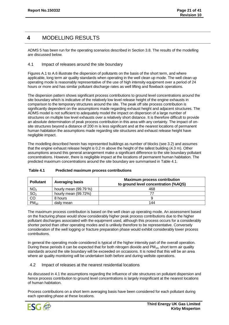
Report No.150332 Page 21 of 41
Revision 10
Third Energy UK Gas Limited
Kirby Misperton
4 MODELLING RESULTS
ADMS 5 has been run for the operating scenarios described in Section 3.8. The results of the modelling are discussed below.
4.1 Impact of releases around the site boundary Figures A.1 to A.6 illustrate the dispersion of pollutants on the basis of the short term, and where applicable, long term air quality standards when operating in the well clean up mode. The well clean up operating mode is reasonably representative of the use of high intensity equipment over a period of 24 hours or more and has similar pollutant discharge rates as well lifting and flowback operations. The dispersion pattern shows significant process contributions to ground level concentrations around the site boundary which is indicative of the relatively low level release height of the engine exhausts in comparison to the temporary structures around the site. The peak off site process contribution is significantly dependent on the assumptions made regarding exhaust height and adjacent structures. The ADMS model is not sufficient to adequately model the impact on dispersion of a large number of structures on multiple low level exhausts over a relatively short distance. It is therefore difficult to provide an absolute determination of peak process contribution in this area with any certainty. The impact of on-site structures beyond a distance of 200 m is less significant and at the nearest locations of permanent human habitation the assumptions made regarding site structures and exhaust release height have negligible impact. The modelling described herein has represented buildings as number of blocks (see 3.2) and assumes that the engine exhaust release height is 0.2 m above the height of the tallest building (4.3 m). Other assumptions around this general arrangement make a significant difference to the site boundary pollutant concentrations. However, there is negligible impact at the locations of permanent human habitation. The predicted maximum concentrations around the site boundary are summarised in Table 4.1.
Table 4.1 Predicted maximum process contributions
Pollutant Averaging basis Maximum process contribution
to ground level concentration (%AQS)
NO2 hourly mean (99.79 %) 468
SO2 hourly mean (99.72%) 77
CO 8 hours 9
PM10 daily mean 144
The maximum process contribution is based on the well clean up operating mode. An assessment based on the fracturing phase would show considerably higher peak process contributions due to the higher pollutant discharges associated with the equipment used, although this process occurs for a considerably shorter period than other operating modes and is unlikely therefore to be representative. Conversely consideration of the well logging or fracture preparation phase would exhibit considerably lower process contributions. In general the operating mode considered is typical of the higher intensity part of the overall operation. During these periods it can be expected that for both nitrogen dioxide and PM10, short term air quality standards around the site boundary will be exceeded on occasions. It is noted that this will be an area where air quality monitoring will be undertaken both before and during wellsite operations.
4.2 Impact of releases at the nearest residential locations As discussed in 4.1 the assumptions regarding the influence of site structures on pollutant dispersion and hence process contribution to ground level concentrations is largely insignificant at the nearest locations of human habitation. Process contributions on a short term averaging basis have been considered for each pollutant during each operating phase at these locations.
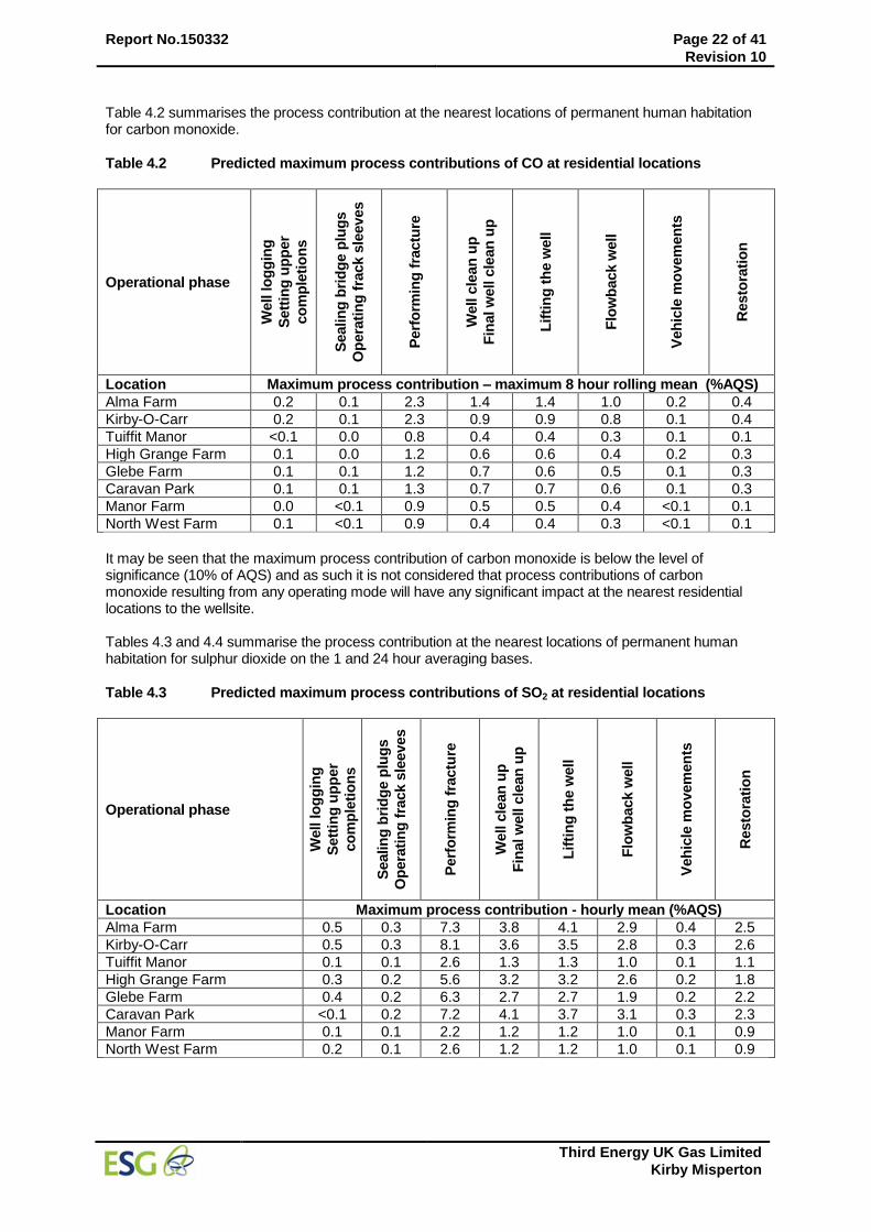
Report No.150332 Page 22 of 41
Revision 10
Third Energy UK Gas Limited
Kirby Misperton
Table 4.2 summarises the process contribution at the nearest locations of permanent human habitation for carbon monoxide.
Table 4.2 Predicted maximum process contributions of CO at residential locations
Operational phase
Well lo
gg
ing
Sett
ing
up
per
co
mp
leti
on
s
Sealin
g b
rid
ge p
lug
s
Op
era
tin
g f
rack s
leeves
Perf
orm
ing
fra
ctu
re
Well c
lean
up
Fin
al w
ell c
lean
up
Lif
tin
g t
he w
ell
Flo
wb
ack w
ell
Veh
icle
mo
vem
en
ts
Resto
rati
on
Location Maximum process contribution – maximum 8 hour rolling mean (%AQS)
Alma Farm 0.2 0.1 2.3 1.4 1.4 1.0 0.2 0.4
Kirby-O-Carr 0.2 0.1 2.3 0.9 0.9 0.8 0.1 0.4
Tuiffit Manor <0.1 0.0 0.8 0.4 0.4 0.3 0.1 0.1
High Grange Farm 0.1 0.0 1.2 0.6 0.6 0.4 0.2 0.3
Glebe Farm 0.1 0.1 1.2 0.7 0.6 0.5 0.1 0.3
Caravan Park 0.1 0.1 1.3 0.7 0.7 0.6 0.1 0.3
Manor Farm 0.0 <0.1 0.9 0.5 0.5 0.4 <0.1 0.1
North West Farm 0.1 <0.1 0.9 0.4 0.4 0.3 <0.1 0.1
It may be seen that the maximum process contribution of carbon monoxide is below the level of significance (10% of AQS) and as such it is not considered that process contributions of carbon monoxide resulting from any operating mode will have any significant impact at the nearest residential locations to the wellsite. Tables 4.3 and 4.4 summarise the process contribution at the nearest locations of permanent human habitation for sulphur dioxide on the 1 and 24 hour averaging bases.
Table 4.3 Predicted maximum process contributions of SO2 at residential locations
Operational phase
Well lo
gg
ing
Sett
ing
up
per
co
mp
leti
on
s
Sealin
g b
rid
ge p
lug
s
Op
era
tin
g f
rack s
leeves
Perf
orm
ing
fra
ctu
re
Well c
lean
up
Fin
al w
ell c
lean
up
Lif
tin
g t
he w
ell
Flo
wb
ack w
ell
Veh
icle
mo
vem
en
ts
Resto
rati
on
Location Maximum process contribution - hourly mean (%AQS)
Alma Farm 0.5 0.3 7.3 3.8 4.1 2.9 0.4 2.5
Kirby-O-Carr 0.5 0.3 8.1 3.6 3.5 2.8 0.3 2.6
Tuiffit Manor 0.1 0.1 2.6 1.3 1.3 1.0 0.1 1.1
High Grange Farm 0.3 0.2 5.6 3.2 3.2 2.6 0.2 1.8
Glebe Farm 0.4 0.2 6.3 2.7 2.7 1.9 0.2 2.2
Caravan Park <0.1 0.2 7.2 4.1 3.7 3.1 0.3 2.3
Manor Farm 0.1 0.1 2.2 1.2 1.2 1.0 0.1 0.9
North West Farm 0.2 0.1 2.6 1.2 1.2 1.0 0.1 0.9
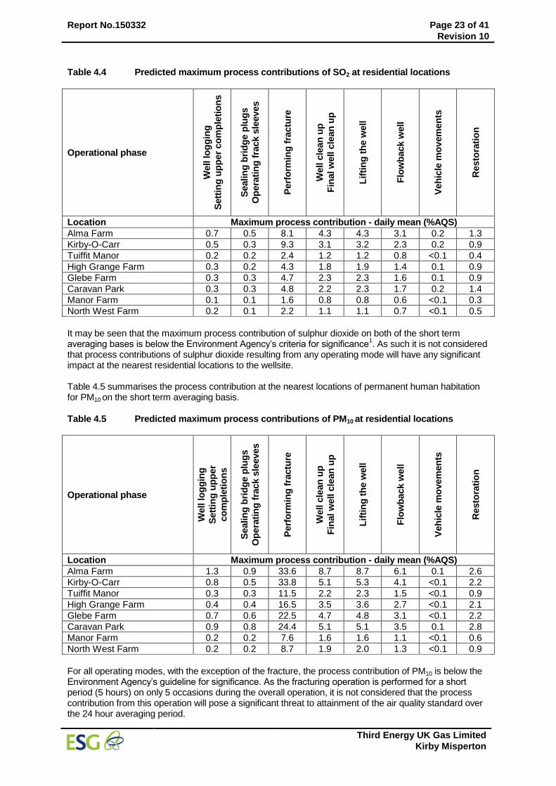
Report No.150332 Page 23 of 41
Revision 10
Third Energy UK Gas Limited
Kirby Misperton
Table 4.4 Predicted maximum process contributions of SO2 at residential locations
Operational phase
Well lo
gg
ing
Sett
ing
up
per
co
mp
leti
on
s
Sealin
g b
rid
ge p
lug
s
Op
era
tin
g f
rack s
leeves
Perf
orm
ing
fra
ctu
re
Well c
lean
up
Fin
al w
ell c
lean
up
Lif
tin
g t
he w
ell
Flo
wb
ack w
ell
Veh
icle
mo
vem
en
ts
Resto
rati
on
Location Maximum process contribution - daily mean (%AQS)
Alma Farm 0.7 0.5 8.1 4.3 4.3 3.1 0.2 1.3
Kirby-O-Carr 0.5 0.3 9.3 3.1 3.2 2.3 0.2 0.9
Tuiffit Manor 0.2 0.2 2.4 1.2 1.2 0.8 <0.1 0.4
High Grange Farm 0.3 0.2 4.3 1.8 1.9 1.4 0.1 0.9
Glebe Farm 0.3 0.3 4.7 2.3 2.3 1.6 0.1 0.9
Caravan Park 0.3 0.3 4.8 2.2 2.3 1.7 0.2 1.4
Manor Farm 0.1 0.1 1.6 0.8 0.8 0.6 <0.1 0.3
North West Farm 0.2 0.1 2.2 1.1 1.1 0.7 <0.1 0.5
It may be seen that the maximum process contribution of sulphur dioxide on both of the short term averaging bases is below the Environment Agency’s criteria for significance
1. As such it is not considered
that process contributions of sulphur dioxide resulting from any operating mode will have any significant impact at the nearest residential locations to the wellsite. Table 4.5 summarises the process contribution at the nearest locations of permanent human habitation for PM10 on the short term averaging basis.
Table 4.5 Predicted maximum process contributions of PM10 at residential locations
Operational phase
Well lo
gg
ing
Sett
ing
up
per
co
mp
leti
on
s
Sealin
g b
rid
ge p
lug
s
Op
era
tin
g f
rack s
leeves
Perf
orm
ing
fra
ctu
re
Well c
lean
up
Fin
al w
ell c
lean
up
Lif
tin
g t
he w
ell
Flo
wb
ack w
ell
Veh
icle
mo
vem
en
ts
Resto
rati
on
Location Maximum process contribution - daily mean (%AQS)
Alma Farm 1.3 0.9 33.6 8.7 8.7 6.1 0.1 2.6
Kirby-O-Carr 0.8 0.5 33.8 5.1 5.3 4.1 <0.1 2.2
Tuiffit Manor 0.3 0.3 11.5 2.2 2.3 1.5 <0.1 0.9
High Grange Farm 0.4 0.4 16.5 3.5 3.6 2.7 <0.1 2.1
Glebe Farm 0.7 0.6 22.5 4.7 4.8 3.1 <0.1 2.2
Caravan Park 0.9 0.8 24.4 5.1 5.1 3.5 0.1 2.8
Manor Farm 0.2 0.2 7.6 1.6 1.6 1.1 <0.1 0.6
North West Farm 0.2 0.2 8.7 1.9 2.0 1.3 <0.1 0.9
For all operating modes, with the exception of the fracture, the process contribution of PM10 is below the Environment Agency’s guideline for significance. As the fracturing operation is performed for a short period (5 hours) on only 5 occasions during the overall operation, it is not considered that the process contribution from this operation will pose a significant threat to attainment of the air quality standard over the 24 hour averaging period.
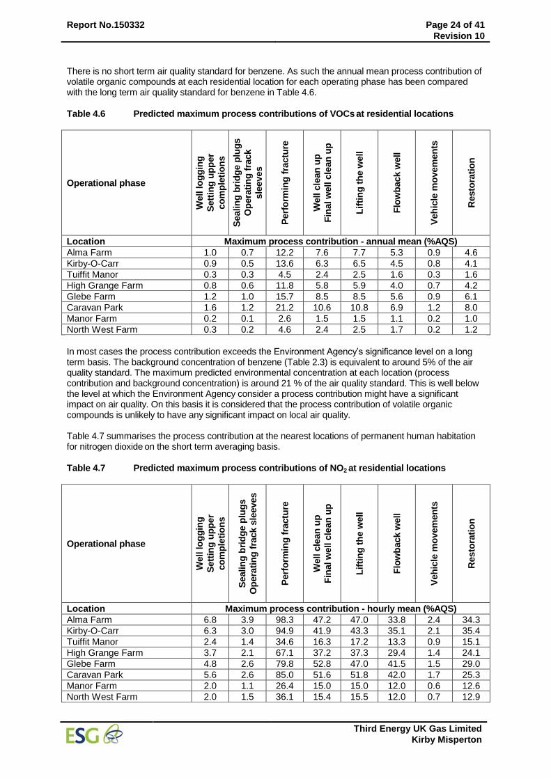
Report No.150332 Page 24 of 41
Revision 10
Third Energy UK Gas Limited
Kirby Misperton
There is no short term air quality standard for benzene. As such the annual mean process contribution of volatile organic compounds at each residential location for each operating phase has been compared with the long term air quality standard for benzene in Table 4.6.
Table 4.6 Predicted maximum process contributions of VOCs at residential locations
Operational phase
Well lo
gg
ing
Sett
ing
up
per
co
mp
leti
on
s
Sealin
g b
rid
ge p
lug
s
Op
era
tin
g f
rack
sle
eves
Perf
orm
ing
fra
ctu
re
Well c
lean
up
Fin
al w
ell c
lean
up
Lif
tin
g t
he w
ell
Flo
wb
ack w
ell
Veh
icle
mo
vem
en
ts
Resto
rati
on
Location Maximum process contribution - annual mean (%AQS)
Alma Farm 1.0 0.7 12.2 7.6 7.7 5.3 0.9 4.6
Kirby-O-Carr 0.9 0.5 13.6 6.3 6.5 4.5 0.8 4.1
Tuiffit Manor 0.3 0.3 4.5 2.4 2.5 1.6 0.3 1.6
High Grange Farm 0.8 0.6 11.8 5.8 5.9 4.0 0.7 4.2
Glebe Farm 1.2 1.0 15.7 8.5 8.5 5.6 0.9 6.1
Caravan Park 1.6 1.2 21.2 10.6 10.8 6.9 1.2 8.0
Manor Farm 0.2 0.1 2.6 1.5 1.5 1.1 0.2 1.0
North West Farm 0.3 0.2 4.6 2.4 2.5 1.7 0.2 1.2
In most cases the process contribution exceeds the Environment Agency’s significance level on a long term basis. The background concentration of benzene (Table 2.3) is equivalent to around 5% of the air quality standard. The maximum predicted environmental concentration at each location (process contribution and background concentration) is around 21 % of the air quality standard. This is well below the level at which the Environment Agency consider a process contribution might have a significant impact on air quality. On this basis it is considered that the process contribution of volatile organic compounds is unlikely to have any significant impact on local air quality. Table 4.7 summarises the process contribution at the nearest locations of permanent human habitation for nitrogen dioxide on the short term averaging basis.
Table 4.7 Predicted maximum process contributions of NO2 at residential locations
Operational phase
Well lo
gg
ing
Sett
ing
up
per
co
mp
leti
on
s
Sealin
g b
rid
ge p
lug
s
Op
era
tin
g f
rack s
leeves
Perf
orm
ing
fra
ctu
re
Well c
lean
up
Fin
al w
ell c
lean
up
Lif
tin
g t
he w
ell
Flo
wb
ack w
ell
Veh
icle
mo
vem
en
ts
Resto
rati
on
Location Maximum process contribution - hourly mean (%AQS)
Alma Farm 6.8 3.9 98.3 47.2 47.0 33.8 2.4 34.3
Kirby-O-Carr 6.3 3.0 94.9 41.9 43.3 35.1 2.1 35.4
Tuiffit Manor 2.4 1.4 34.6 16.3 17.2 13.3 0.9 15.1
High Grange Farm 3.7 2.1 67.1 37.2 37.3 29.4 1.4 24.1
Glebe Farm 4.8 2.6 79.8 52.8 47.0 41.5 1.5 29.0
Caravan Park 5.6 2.6 85.0 51.6 51.8 42.0 1.7 25.3
Manor Farm 2.0 1.1 26.4 15.0 15.0 12.0 0.6 12.6
North West Farm 2.0 1.5 36.1 15.4 15.5 12.0 0.7 12.9
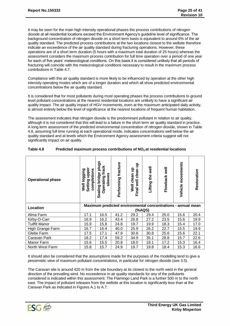
Report No.150332 Page 25 of 41
Revision 10
Third Energy UK Gas Limited
Kirby Misperton
It may be seen for the main high intensity operational phases the process contributions of nitrogen dioxide at all residential locations exceed the Environment Agency’s guideline level of significance. The background concentration of nitrogen dioxide on a short term basis is equivalent to around 6% of the air quality standard. The predicted process contributions at the two locations closest to the wellsite therefore indicate an exceedence of the air quality standard during fracturing operations. However, these operations are of a short term duration (5 hours with a maximum total duration of 25 hours) whereas the assessment considers the maximum process contribution for full time operation over a period of one year for each of five years’ meteorological conditions. On this basis it is considered unlikely that all periods of fracturing will coincide with the meteorological conditions necessary to result in the maximum process contributions in Table 4.7. Compliance with this air quality standard is more likely to be influenced by operation at the other high intensity operating modes which are of a longer duration and which all show predicted environmental concentrations below the air quality standard. It is considered that for most pollutants during most operating phases the process contributions to ground level pollutant concentrations at the nearest residential locations are unlikely to have a significant air quality impact. The air quality impact of HGV movements, even at the maximum anticipated daily activity, is almost entirely below the level of significance at the nearest locations of frequent human habitation. The assessment indicates that nitrogen dioxide is the predominant pollutant in relation to air quality, although it is not considered that this will lead to a failure in the short term air quality standard in practice. A long term assessment of the predicted environmental concentration of nitrogen dioxide, shown in Table 4.8, assuming full time running at each operational mode, indicates concentrations well below the air quality standard and at levels which the Environment Agency assessment criteria suggest will not significantly impact on air quality.
Table 4.8 Predicted maximum process contributions of NO2 at residential locations
Operational phase
Well lo
gg
ing
Sett
ing
up
per
co
mp
leti
on
s
Sealin
g b
rid
ge p
lug
s
Op
era
tin
g f
rack
sle
eves
Perf
orm
ing
fra
ctu
re
Well c
lean
up
Fin
al w
ell c
lean
up
Lif
tin
g t
he w
ell
Flo
wb
ack w
ell
Veh
icle
mo
vem
en
ts
Resto
rati
on
Location Maximum predicted environmental concentrations - annual mean
(%AQS)
Alma Farm 17.1 16.5 41.2 29.2 29.4 25.0 15.6 20.4
Kirby-O-Carr 16.9 16.2 43.4 26.8 27.2 23.5 15.6 19.9
Tuiffit Manor 15.9 15.8 24.8 19.7 19.9 18.3 15.4 17.0
High Grange Farm 16.7 16.4 40.0 25.9 26.2 22.7 15.5 19.9
Glebe Farm 17.5 17.1 47.9 30.8 30.8 25.6 15.6 22.1
Caravan Park 18.2 17.4 59.2 34.9 35.1 28.8 15.7 22.6
Manor Farm 15.6 15.5 20.8 18.0 18.1 17.2 15.3 16.4
North West Farm 15.8 15.7 24.9 19.7 19.8 18.4 15.3 16.6
It should also be considered that the assumptions made for the purposes of the modelling tend to give a pessimistic view of maximum pollutant concentrations, in particular for nitrogen dioxide (see 3.5). The Caravan site is around 420 m from the site boundary at its closest to the north west in the general direction of the prevailing wind. No exceedence in air quality standards for any of the pollutants considered is indicated within this assessment. The Flamingo Land Park is a further 500 m to the north east. The impact of pollutant releases from the wellsite at this location is significantly less than at the Caravan Park as indicated in Figures A.1 to A.7.
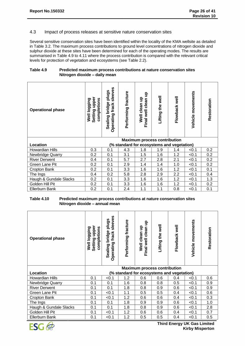
Report No.150332 Page 26 of 41
Revision 10
Third Energy UK Gas Limited
Kirby Misperton
4.3 Impact of process releases at sensitive nature conservation sites Several sensitive conservation sites have been identified within the locality of the KMA wellsite as detailed in Table 3.2. The maximum process contributions to ground level concentrations of nitrogen dioxide and sulphur dioxide at these sites have been determined for each of the operating modes. The results are summarised in Table 4.9 to 4.11 where the process contribution is compared with the relevant critical levels for protection of vegetation and ecosystems (see Table 2.2).
Table 4.9 Predicted maximum process contributions at nature conservation sites
Nitrogen dioxide – daily mean
Operational phase
Well lo
gg
ing
Sett
ing
up
per
co
mp
leti
on
s
Sealin
g b
rid
ge p
lug
s
Op
era
tin
g f
rack s
leeves
Perf
orm
ing
fra
ctu
re
Well c
lean
up
Fin
al w
ell c
lean
up
Lif
tin
g t
he w
ell
Flo
wb
ack w
ell
Veh
icle
mo
vem
en
ts
Resto
rati
on
Location
Maximum process contribution
(% standard for ecosystems and vegetation)
Howardian Hills 0.3 0.1 4.3 1.8 1.9 1.4 <0.1 0.2
Newbridge Quarry 0.2 0.1 3.1 1.5 1.6 1.2 <0.1 0.2
River Derwent 0.4 0.1 5.7 2.7 2.8 2.1 <0.1 0.2
Green Lane Pit 0.2 0.1 2.9 1.4 1.4 1.0 <0.1 0.2
Cropton Bank 0.2 0.1 3.3 1.6 1.6 1.2 <0.1 0.1
The Ings 0.4 0.2 5.8 2.8 2.9 2.2 <0.1 0.4
Haugh & Gundale Slacks 0.2 0.1 3.3 1.6 1.6 1.2 <0.1 1.3
Golden Hill Pit 0.2 0.1 3.3 1.6 1.6 1.2 <0.1 0.2
Ellerburn Bank 0.2 0.1 2.4 1.1 1.1 0.8 <0.1 0.1
Table 4.10 Predicted maximum process contributions at nature conservation sites
Nitrogen dioxide – annual mean
Operational phase
Well lo
gg
ing
Sett
ing
up
per
co
mp
leti
on
s
Sealin
g b
rid
ge p
lug
s
Op
era
tin
g f
rack s
leeves
Perf
orm
ing
fra
ctu
re
Well c
lean
up
Fin
al w
ell c
lean
up
Lif
tin
g t
he w
ell
Flo
wb
ack w
ell
Veh
icle
mo
vem
en
ts
Resto
rati
on
Location
Maximum process contribution
(% standard for ecosystems and vegetation)
Howardian Hills 0.1 <0.1 1.2 0.6 0.6 0.4 <0.1 0.6
Newbridge Quarry 0.1 0.1 1.6 0.8 0.8 0.5 <0.1 0.9
River Derwent 0.1 0.1 1.8 0.8 0.9 0.6 <0.1 0.9
Green Lane Pit 0.1 <0.1 1.1 0.5 0.5 0.4 <0.1 0.6
Cropton Bank 0.1 <0.1 1.2 0.6 0.6 0.4 <0.1 0.3
The Ings 0.1 0.1 1.8 0.9 0.9 0.6 <0.1 1.0
Haugh & Gundale Slacks 0.1 0.1 1.8 0.8 0.9 0.6 <0.1 2.8
Golden Hill Pit 0.1 <0.1 1.2 0.6 0.6 0.4 <0.1 0.7
Ellerburn Bank 0.1 <0.1 1.2 0.5 0.5 0.4 <0.1 0.5
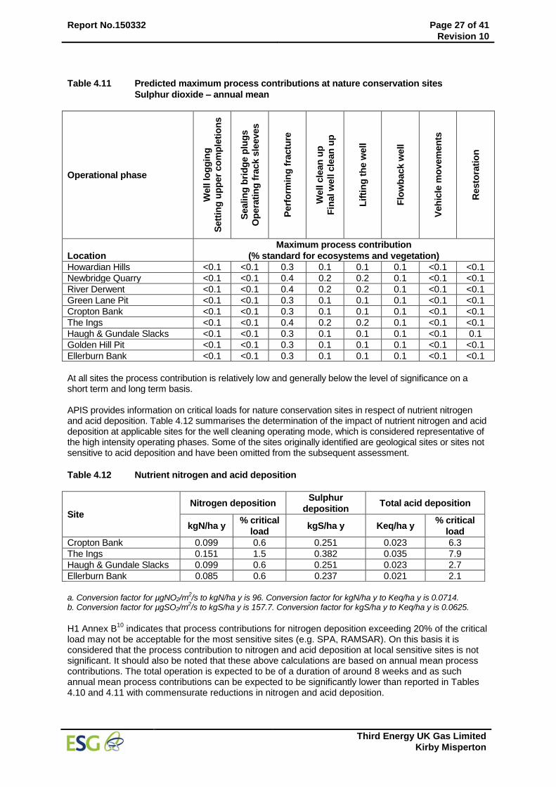
Report No.150332 Page 27 of 41
Revision 10
Third Energy UK Gas Limited
Kirby Misperton
Table 4.11 Predicted maximum process contributions at nature conservation sites
Sulphur dioxide – annual mean
Operational phase
Well lo
gg
ing
Sett
ing
up
per
co
mp
leti
on
s
Sealin
g b
rid
ge p
lug
s
Op
era
tin
g f
rack s
leeves
Perf
orm
ing
fra
ctu
re
Well c
lean
up
Fin
al w
ell c
lean
up
Lif
tin
g t
he w
ell
Flo
wb
ack w
ell
Veh
icle
mo
vem
en
ts
Resto
rati
on
Location
Maximum process contribution
(% standard for ecosystems and vegetation)
Howardian Hills <0.1 <0.1 0.3 0.1 0.1 0.1 <0.1 <0.1
Newbridge Quarry <0.1 <0.1 0.4 0.2 0.2 0.1 <0.1 <0.1
River Derwent <0.1 <0.1 0.4 0.2 0.2 0.1 <0.1 <0.1
Green Lane Pit <0.1 <0.1 0.3 0.1 0.1 0.1 <0.1 <0.1
Cropton Bank <0.1 <0.1 0.3 0.1 0.1 0.1 <0.1 <0.1
The Ings <0.1 <0.1 0.4 0.2 0.2 0.1 <0.1 <0.1
Haugh & Gundale Slacks <0.1 <0.1 0.3 0.1 0.1 0.1 <0.1 0.1
Golden Hill Pit <0.1 <0.1 0.3 0.1 0.1 0.1 <0.1 <0.1
Ellerburn Bank <0.1 <0.1 0.3 0.1 0.1 0.1 <0.1 <0.1
At all sites the process contribution is relatively low and generally below the level of significance on a short term and long term basis. APIS provides information on critical loads for nature conservation sites in respect of nutrient nitrogen and acid deposition. Table 4.12 summarises the determination of the impact of nutrient nitrogen and acid deposition at applicable sites for the well cleaning operating mode, which is considered representative of the high intensity operating phases. Some of the sites originally identified are geological sites or sites not sensitive to acid deposition and have been omitted from the subsequent assessment.
Table 4.12 Nutrient nitrogen and acid deposition
Site
Nitrogen deposition Sulphur
deposition Total acid deposition
kgN/ha y % critical
load kgS/ha y Keq/ha y
% critical
load
Cropton Bank 0.099 0.6 0.251 0.023 6.3
The Ings 0.151 1.5 0.382 0.035 7.9
Haugh & Gundale Slacks 0.099 0.6 0.251 0.023 2.7
Ellerburn Bank 0.085 0.6 0.237 0.021 2.1
a. Conversion factor for µgNO2/m
2/s to kgN/ha y is 96. Conversion factor for kgN/ha y to Keq/ha y is 0.0714.
b. Conversion factor for µgSO2/m2/s to kgS/ha y is 157.7. Conversion factor for kgS/ha y to Keq/ha y is 0.0625.
H1 Annex B
10 indicates that process contributions for nitrogen deposition exceeding 20% of the critical
load may not be acceptable for the most sensitive sites (e.g. SPA, RAMSAR). On this basis it is considered that the process contribution to nitrogen and acid deposition at local sensitive sites is not significant. It should also be noted that these above calculations are based on annual mean process contributions. The total operation is expected to be of a duration of around 8 weeks and as such annual mean process contributions can be expected to be significantly lower than reported in Tables 4.10 and 4.11 with commensurate reductions in nitrogen and acid deposition.
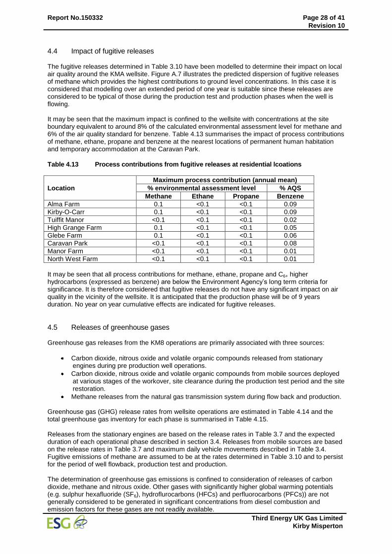
Report No.150332 Page 28 of 41
Revision 10
Third Energy UK Gas Limited
Kirby Misperton
4.4 Impact of fugitive releases The fugitive releases determined in Table 3.10 have been modelled to determine their impact on local air quality around the KMA wellsite. Figure A.7 illustrates the predicted dispersion of fugitive releases of methane which provides the highest contributions to ground level concentrations. In this case it is considered that modelling over an extended period of one year is suitable since these releases are considered to be typical of those during the production test and production phases when the well is flowing. It may be seen that the maximum impact is confined to the wellsite with concentrations at the site boundary equivalent to around 8% of the calculated environmental assessment level for methane and 6% of the air quality standard for benzene. Table 4.13 summarises the impact of process contributions of methane, ethane, propane and benzene at the nearest locations of permanent human habitation and temporary accommodation at the Caravan Park.
Table 4.13 Process contributions from fugitive releases at residential lcoations
Location
Maximum process contribution (annual mean)
% environmental assessment level % AQS
Methane Ethane Propane Benzene
Alma Farm 0.1 <0.1 <0.1 0.09
Kirby-O-Carr 0.1 <0.1 <0.1 0.09
Tuiffit Manor <0.1 <0.1 <0.1 0.02
High Grange Farm 0.1 <0.1 <0.1 0.05
Glebe Farm 0.1 <0.1 <0.1 0.06
Caravan Park <0.1 <0.1 <0.1 0.08
Manor Farm <0.1 <0.1 <0.1 0.01
North West Farm <0.1 <0.1 <0.1 0.01
It may be seen that all process contributions for methane, ethane, propane and C6+ higher hydrocarbons (expressed as benzene) are below the Environment Agency’s long term criteria for significance. It is therefore considered that fugitive releases do not have any significant impact on air quality in the vicinity of the wellsite. It is anticipated that the production phase will be of 9 years duration. No year on year cumulative effects are indicated for fugitive releases.
4.5 Releases of greenhouse gases Greenhouse gas releases from the KM8 operations are primarily associated with three sources:
Carbon dioxide, nitrous oxide and volatile organic compounds released from stationary engines during pre production well operations.
Carbon dioxide, nitrous oxide and volatile organic compounds from mobile sources deployed at various stages of the workover, site clearance during the production test period and the site restoration.
Methane releases from the natural gas transmission system during flow back and production. Greenhouse gas (GHG) release rates from wellsite operations are estimated in Table 4.14 and the total greenhouse gas inventory for each phase is summarised in Table 4.15. Releases from the stationary engines are based on the release rates in Table 3.7 and the expected duration of each operational phase described in section 3.4. Releases from mobile sources are based on the release rates in Table 3.7 and maximum daily vehicle movements described in Table 3.4. Fugitive emissions of methane are assumed to be at the rates determined in Table 3.10 and to persist for the period of well flowback, production test and production. The determination of greenhouse gas emissions is confined to consideration of releases of carbon dioxide, methane and nitrous oxide. Other gases with significantly higher global warming potentials (e.g. sulphur hexafluoride (SF6), hydroflurocarbons (HFCs) and perfluorocarbons (PFCs)) are not generally considered to be generated in significant concentrations from diesel combustion and emission factors for these gases are not readily available.
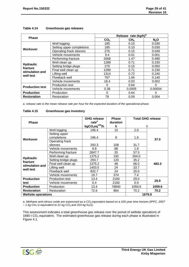
Report No.150332 Page 29 of 41
Revision 10
Third Energy UK Gas Limited
Kirby Misperton
Table 4.14 Greenhouse gas releases
Phase Release rate (kg/h)
a
CO2 CH4 N2O
Workover
Well logging 185 0.10 0.030
Setting upper completions 185 0.10 0.030
Operating frack sleeves 275 0.15 0.049
Vehicle movements 9.4 0.01 0.001
Hydraulic
fracture
stimulation and
well test
Performing fracture 2668 1.47 0.480
Well clean up 1289 0.71 0.230
Setting bridge plugs 275 0.15 0.050
Final well clean up 1289 0.71 0.230
Lifting well 1314 0.72 0.240
Flowback well 767 1.06 0.140
Vehicle movements 18.4 0.03 0.002
Production test Production test 0 0.64 0
Vehicle movements 0.38 0.0005 0.00004
Production Production 0 0.64 0
Restoration Restoration 78 0.09 0.004
a. release rate is the mean release rate per hour for the expected duration of the operational phase.
Table 4.15 Greenhouse gas inventory
Phase
GHG release
ratea
Phase
duration
Total GHG release
kgCO2eq100
/h h t
Workover
Well logging 196.4 10 2.0
37.0
Setting upper completions 196.4 8 1.6
Operating frack sleeves 293.3 108 31.7
Vehicle movements 9.9 88 1.8
Hydraulic
fracture
stimulation and
well test
Performing fracture 2847.7 20 57.0
483.3
Well clean up 1375.2 192 264.0
Setting bridge plugs 293.7 120 35.2
Final well clean up 1375.2 48 66.0
Lifting well 1403.5 24 33.7
Flowback well 832.7 24 20.0
Vehicle movements 19.7 374 7.4
Production
test
Production test 13.4 2160 29.0 29.9
Vehicle movements 0.4 2160 0.9
Production Production 13.4 78840 1059.6 1059.6
Restoration Restoration 72.6 864 70.2 70.2
Wellsite operations 1679.9
a. Methane and nitrous oxide are expressed as a CO2 equivalent based on a 100 year time horizon (IPPC, 2007 – 1 kg CH4 is equivalent to 21 kg CO2 and 310 kg N2O).
This assessment indicates a total greenhouse gas release over the period of wellsite operations of 1680 t CO2 equivalent. The estimated greenhouse gas release during each phase is illustrated in Figure 4.1.
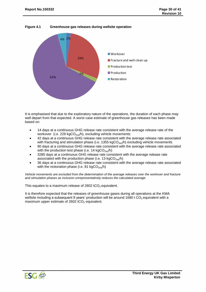
Report No.150332 Page 30 of 41
Revision 10
Third Energy UK Gas Limited
Kirby Misperton
Figure 4.1 Greenhouse gas releases during wellsite operation
2%
29%
2%63%
4%
Workover
Fracture and well clean up
Production test
Production
Restoration
It is emphasised that due to the exploratory nature of the operations, the duration of each phase may well depart from that expected. A worst case estimate of greenhouse gas releases has been made based on:
14 days at a continuous GHG release rate consistent with the average release rate of the workover (i.e. 229 kgCO2eq/h), excluding vehicle movements
42 days at a continuous GHG release rate consistent with the average release rate associated with fracturing and stimulation phase (i.e. 1355 kgCO2eq/h) excluding vehicle movements
90 days at a continuous GHG release rate consistent with the average release rate associated with the production test phase (i.e. 14 kgCO2eq/h)
3285 days at a continuous GHG release rate consistent with the average release rate associated with the production phase (i.e. 13 kgCO2eq/h)
36 days at a continuous GHG release rate consistent with the average release rate associated with the restoration phase (i.e. 81 kgCO2eq/h)
Vehicle movements are excluded from the determination of the average releases over the workover and fracture and stimulation phases as inclusion unrepresentatively reduces the calculated average.
This equates to a maximum release of 2602 tCO2 equivalent. It is therefore expected that the releases of greenhouse gases during all operations at the KMA wellsite including a subsequent 9 years’ production will be around 1680 t CO2 equivalent with a maximum upper estimate of 2602 tCO2 equivalent.
Report No.150332 Page 31 of 41
Revision 10
Third Energy UK Gas Limited
Kirby Misperton
5 CONCLUSIONS
A dispersion modelling assessment using the ADMS 5 model was employed to predict the impact on local air quality of discharges of important pollutants from well operations at the Kirby Misperton A (KMA) wellsite. All operating phases associated with the well workover, fracturing, subsequent clean up and demobilisation prior to production were considered with emphasis on releases from temporary operations equipment, largely stationary diesel engines, and fugitive emissions from the natural gas transmission system. The greenhouse gas inventory for the operation was also assessed. Process contributions from engine releases to ground level concentrations of nitrogen dioxide and PM10 are expected to exceed short term air quality standards at the site boundary based on model predictions, although the extent of any exceedence is not clear due to the influence of temporary structures on the dispersion of low level engine exhaust releases. At the nearest locations of permanent human habitation process contributions to ground level concentrations of carbon monoxide, sulphur dioxide, volatile organic compounds and PM10 are not considered to be likely to have any significant impact on air quality. Process contributions of nitrogen dioxide are more significant, although it is concluded that these are unlikely to pose a substantial threat to the continued attainment of air quality standards. At the closest statutory designated nature conservation sites process contributions to ground level concentrations of sulphur dioxide and nitrogen dioxide are mostly below the level of significance and do not pose any substantial risk to attainment of the critical levels. Nutrient nitrogen and acid deposition associated with the process contributions at these locations are not considered to be significant in relation to corresponding critical loads. Natural gas produced from the KMA wellsite is transported via pipeline to the nearby Knapton Generating Station. Fugitive releases of natural gas are expected from the on site gas transmission system. Based on leakage rates assessed by Third Energy the impact on local air quality of fugitive natural gas releases was assessed. The maximum process contribution to ground level concentrations of methane, ethane , propane and higher hydrocarbons (expressed as benzene) was predicted to be equivalent to no more than 8% of the estimated long term environmental benchmark at the site boundary falling to below 1% of these levels at the nearest residential locations. The long term process contribution to ground level concentrations of these compounds during both pre production and production phases of well operations is not considered to be significant based on Environment Agency assessment criteria. The modelling assessment methodology and necessary assumptions provide a very conservative assessment of impact on air quality, particularly for nitrogen dioxide. The overall results and conclusions reached therefore incorporate a reasonable margin of comfort in spite of the inevitable uncertainty of such modelling studies. It is concluded that the well operations will not affect the attainment of air quality standards around the areas of permanent human habitation closest to the wellsite and will have negligible impact at local statutory designated conservation sites. Exceedences in short term air quality standards for some pollutants are likely on occasions around the site boundary. No exceedence in air quality standards is indicated for the locations of temporary habitation in the Caravan Park and nearby Flamingo Land Theme Park. Release of greenhouse gases during well operations are estimated to be around 1680 t CO2 equivalent, based on the expected duration of the defined operational phases. Due to the inherent uncertainty of this type of project the duration of some phases may exceed initial expectations and as such an estimate of 2602 tCO2 equivalent is provided as a maximum for the overall project.
Report No.150332 Page 32 of 41
Revision 10
Third Energy UK Gas Limited
Kirby Misperton
6 REFERENCES
1. Environment Agency, “Horizontal guidance note H1 – Annex (f) Air Emissions”, version 2.2, December 2011.
2. Directive 2008/50/EC – Ambient air quality and cleaner air for Europe, 21 May 2008.
3. Health and Safety Executive, EH40/2005 Workplace exposure limits, 2011. 4. Occupation Health and Safety Administration, Permissible exposure limits, US Department of
Labor, September 1976.
5. Environment Agency, ‘Review of background air quality data and methods to combine these with process contributions: technical modelling aspects’, Science report SC030174/1SR2, October 2006.
6. Personal communication, J Foster (PSSL) to N Ford, 23 February 2015. 7. Personal communication, N Dugnaite (Haliburton) to N Ford, 27 March 2015. 8. ‘Compilation of Air Pollutant Emission Factors’, Volume 1, 5
th Edition, January 1995, United
States Environmental Protection Agency. 9. Janssen LHJM, Van Wakeren JHA, Van Duuren H and Elshout A J, 1988, A classification of NO oxidation rates in power plant plumes based on atmospheric conditions, Atmospheric Environment, 22, 43-53.
10. Environment Agency, H1 Annex B – Intensive farming, version 2.0, December 2011. 11. Environment Agency, AQTAG06 Technical guidance on detailed modelling approach for an
appropriate assessment for emissions to air, October 2011. 12. S.M. Ashrafur Rahman, Impact of idling on fuel consumption and exhaust emissions and
available idle-reduction technologies for diesel vehicles – A review, Energy conversion and management, 74, 2013.
13. EMEP/EEA, Emissions inventory guidebook 2013, September 2014. 14. United States Environmental Protection Agency, Idling vehicle emission, EPA-420-F-98-014,
April 1998. 15. United States Environmental Protection Agency, Idling vehicle emission, EPA-420-F-98-014,
April 1998.
Report No.150332 Page 33 of 41
Revision 10
Third Energy UK Gas Limited
Kirby Misperton
Annex A Dispersion model contour plots
The results of the modelling of the impact of the well operations on local ambient concentrations of important pollutants are presented in tabular form in Section 4. In Annex A these results are presented as contour plots of the process contribution to ambient concentrations. All results are presented as the maximum contribution of the process operation (excluding existing background concentrations) in µg/m
3,
with the exception of carbon monoxide which is expressed as mg/m3.
The following figures are presented: Figure 1 Predicted concentrations of nitrogen dioxide (99.8 percentile of 1 hour means) from
stationary engine releases during well clean up operations
Figure 2 Predicted concentrations of nitrogen dioxide (annual mean) from stationary engine releases during well clean up operations
Figure 3 Predicted concentrations of carbon monoxide (maximum 8 hour rolling average) from stationary engine releases during well clean up operations
Figure 4 Predicted concentrations of PM10 (90.41 percentile of daily means) from stationary engine releases during well clean up operations
Figure 5 Predicted concentrations of sulphur dioxide (99.72 percentile of hourly means) from stationary engine releases during well clean up operations
Figure 6 Predicted concentrations of volatile organic compounds (annual mean) from stationary engine releases during well clean up operations
Figure 7 Predicted concentrations of methane from fugitive emissions (annual mean)
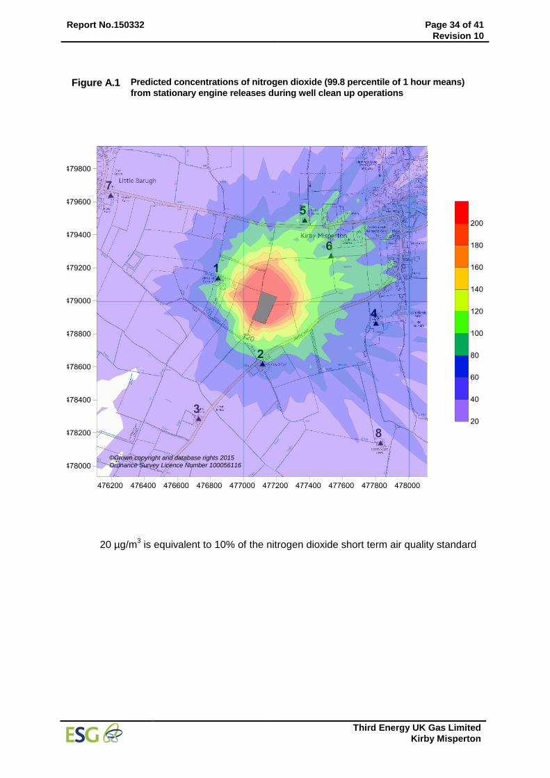
Report No.150332 Page 34 of 41
Revision 10
Third Energy UK Gas Limited
Kirby Misperton
Figure A.1 Predicted concentrations of nitrogen dioxide (99.8 percentile of 1 hour means)
from stationary engine releases during well clean up operations
20 µg/m3 is equivalent to 10% of the nitrogen dioxide short term air quality standard
©Crown copyright and database rights 2015 Ordnance Survey Licence Number 100056116
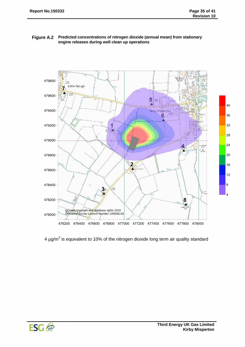
Report No.150332 Page 35 of 41
Revision 10
Third Energy UK Gas Limited
Kirby Misperton
Figure A.2 Predicted concentrations of nitrogen dioxide (annual mean) from stationary
engine releases during well clean up operations
4 µg/m
3 is equivalent to 10% of the nitrogen dioxide long term air quality standard
©Crown copyright and database rights 2015 Ordnance Survey Licence Number 100056116
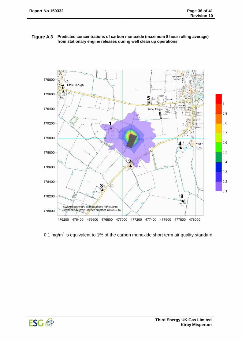
Report No.150332 Page 36 of 41
Revision 10
Third Energy UK Gas Limited
Kirby Misperton
Figure A.3 Predicted concentrations of carbon monoxide (maximum 8 hour rolling average)
from stationary engine releases during well clean up operations
0.1 mg/m
3 is equivalent to 1% of the carbon monoxide short term air quality standard
©Crown copyright and database rights 2015 Ordnance Survey Licence Number 100056116
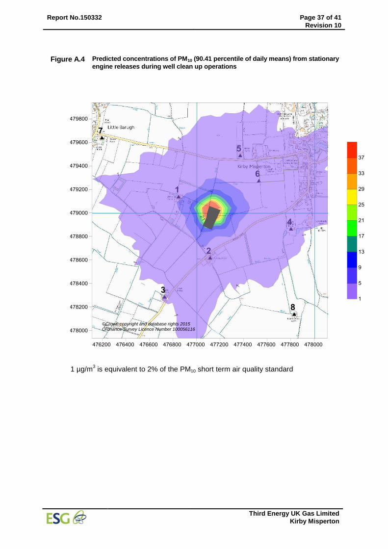
Report No.150332 Page 37 of 41
Revision 10
Third Energy UK Gas Limited
Kirby Misperton
Figure A.4 Predicted concentrations of PM10 (90.41 percentile of daily means) from stationary
engine releases during well clean up operations
1 µg/m
3 is equivalent to 2% of the PM10 short term air quality standard
©Crown copyright and database rights 2015 Ordnance Survey Licence Number 100056116
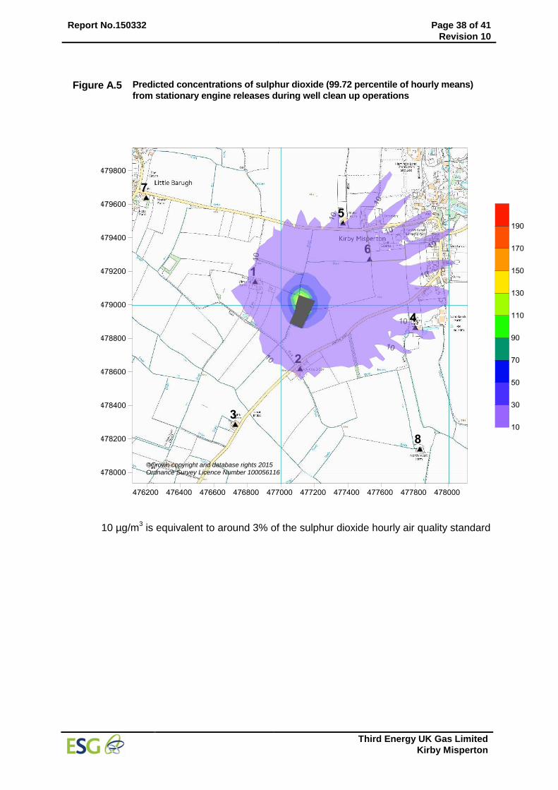
Report No.150332 Page 38 of 41
Revision 10
Third Energy UK Gas Limited
Kirby Misperton
Figure A.5 Predicted concentrations of sulphur dioxide (99.72 percentile of hourly means)
from stationary engine releases during well clean up operations
10 µg/m
3 is equivalent to around 3% of the sulphur dioxide hourly air quality standard
©Crown copyright and database rights 2015 Ordnance Survey Licence Number 100056116
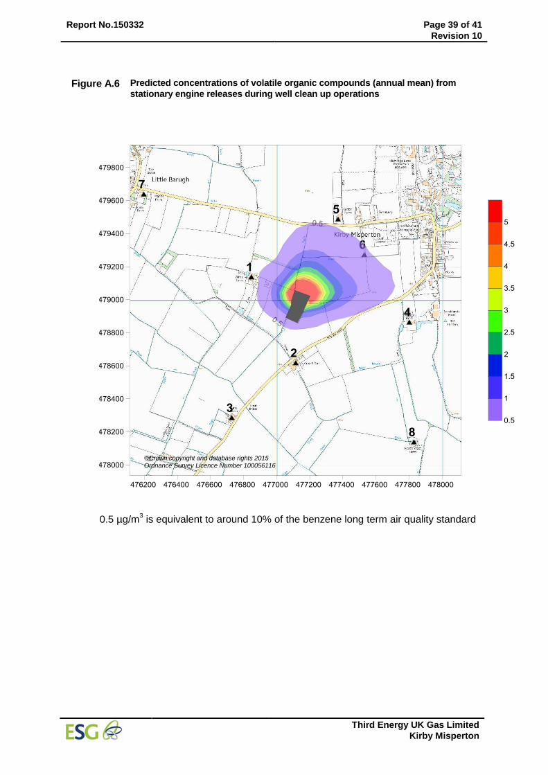
Report No.150332 Page 39 of 41
Revision 10
Third Energy UK Gas Limited
Kirby Misperton
Figure A.6 Predicted concentrations of volatile organic compounds (annual mean) from
stationary engine releases during well clean up operations
0.5 µg/m
3 is equivalent to around 10% of the benzene long term air quality standard
©Crown copyright and database rights 2015 Ordnance Survey Licence Number 100056116
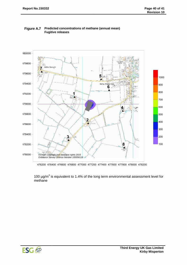
Report No.150332 Page 40 of 41
Revision 10
Third Energy UK Gas Limited
Kirby Misperton
Figure A.7 Predicted concentrations of methane (annual mean)
Fugitive releases
100 µg/m3 is equivalent to 1.4% of the long term environmental assessment level for
methane
©Crown copyright and database rights 2015 Ordnance Survey Licence Number 100056116
Report No.150332 Page 41 of 41
Revision 10
Third Energy UK Gas Limited
Kirby Misperton
ANNEX B Modelling files
The ADMS modelling files detailing the model input for the runs providing maximum hourly mean concentrations have been provided under separate cover and are summarised below:
Operating phase Year File Name
Well logging
2012
KM8 WL 2012.APL
Setting upper completions Same as well logging
Operating frack sleeves KM8 OFS 2012.APL
Vehicle movements KM8 VM 2012.APL
Performing fracture KM8 PF 2012.APL
Well clean up (between zone fractures) KM8 WCU 2012.APL
Setting bridge plugs Same as operating frack sleeves
Final well clean up Same as well clean up
Lifting the well KM8 LTW 2012.APL
Flowback well KM8 FBW 2012
Restoration KM8 SR 2012.APL
Fugitive releases KM8 FUG 2012.APL
END OF REPORT

Contact: Dr Nick Ford Environmental Scientifics Group Ltd Unit D, Acacia Building Vantage Point Business Village Mitcheldean Gloucestershire GL17 0DD T: 07768 257628 E: [email protected]

KM8 Hydraulic Fracturing Operations Waste Management Plan
Uncontrolled if printed KM8 WMP/Rev5/13-06-2017 Page 90
APPENDIX 9 – SITE LAYOUT PLAN

KM8 Hydraulic Fracturing Operations Waste Management Plan
Uncontrolled if printed KM8 WMP/Rev5/13-06-2017 Page 91
**This page has been intentionally left blank**

EP
EP
PSSLPetroleum Safety Services Limited
Key:
Project:KM8 Hydraulic FracturingOperation
Drawing Title:KM8 Pre-StimulationWorkover Layout PlanScale: 1:750 (Print A3)
Drawn By:Jonathan Foster
Drawing No:TE-EPRA-KM8-HFS-SP-09-01
Rev: 0
Date Drawn: 11/08/2015Approved By:Jonathan Foster
Date Approved: 11/08/2015Petroleum Safety Services Limited23a Milton Street
Saltburn by the SeaTS12 1DJ
Client:Third Energy UK Gas Ltd
Lighting Specification Details:
Site BoundaryWater Features (Ponds, Drains)
Public Rights of WayOverhead Electricity CablesBurried Electricity Cables
Water Features Direction of Flow
Underground PipelinesExisting Wellsite Landscaping

EP
EP
PSSLPetroleum Safety Services Limited
Key:
Project:KM8 Hydraulic FracturingOperation
Drawing Title:KM8 Hydraulic Fracture /Well Test Layout PlanScale: 1:750 (Print A3)
Drawn By:Jonathan Foster
Drawing No:TE-EPRA-KM8-HFS-SP-09-02
Rev: 0
Date Drawn: 11/08/2015Approved By:Jonathan Foster
Date Approved: 11/08/2015Petroleum Safety Services Limited23a Milton Street
Saltburn by the seaTS12 1DJ
Client:Third Energy UK Gas Ltd
Lighting Specification Details:
Site BoundaryWater Features (Ponds, Drains)
Public Rights of WayOverhead Electricity CablesBurried Electricity Cables
Water Features Direction of Flow
Underground PipelinesExisting Wellsite Landscaping

EP
EP
PSSLPetroleum Safety Services Limited
Key:
Project:KM8 Hydraulic FracturingOperation
Drawing Title:KM8 Production TestLayout PlanScale: 1:750 (Print A3)
Drawn By:Jonathan Foster
Drawing No:TE-EPRA-KM8-HFS-SP-09-03
Rev: 0
Date Drawn: 11/08/2015Approved By:Jonathan Foster
Date Approved: 11/08/2015Petroleum Safety Services Limited23a Milton Street
Saltburn by the SeaTS12 1DJ
Client:Third Energy UK Gas Ltd
Lighting Specification Details:
Site BoundaryWater Features (Ponds, Drains)
Public Rights of WayOverhead Electricity CablesBurried Electricity Cables
Water Features Direction of Flow
Underground PipelinesExisting Wellsite Landscaping

EP
EP
PSSLPetroleum Safety Services Limited
Key:
Project:KM8 Hydraulic FracturingOperation
Drawing Title:KM8 Production LayoutPlanScale: 1:750 (Print A3)
Drawn By:Jonathan Foster
Drawing No:TE-EPRA-KM8-HFS-SP-09-04
Rev: 0
Date Drawn: 11/08/2015Approved By:Jonathan Foster
Date Approved: 11/08/2015Petroleum Safety Services Limited23a Milton Street
Saltburn by the SeaTS12 1DJ
Client:Third Energy UK Gas Ltd
Lighting Specification Details:
Site BoundaryWater Features (Ponds, Drains)
Public Rights of WayOverhead Electricity CablesBurried Electricity Cables
Water Features Direction of Flow
Underground PipelinesExisting Wellsite Landscaping


