
8/2/2019 KVC - Stainless Steel Valves
http://slidepdf.com/reader/full/kvc-stainless-steel-valves 1/39
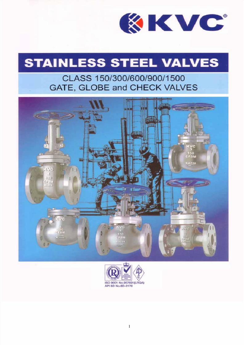
1

8/2/2019 KVC - Stainless Steel Valves
http://slidepdf.com/reader/full/kvc-stainless-steel-valves 2/39
FORWARD
We take the pleasure in presenting our production of KVC® Stainless Steel Gate, Globe and SwingCheck Valves.
KVC® Stainless Steel Valves are widely used in the petroleum refineries and chemical processing
industries and approved by most major oil and gas companies.
KVC® Stainless Steel Valves are designed and manufactured in strict accordance with the
prescriptions and requirement of ASTM, ANSI, API, BS standards to meet the applicable-standards,in addition to KVC Co., Ltd's own ISO 9000-2000 procedure for quality control.
Our basic policy for quality assurance is to manufacture products of excellent quality to obtain greattrust and deep satisfaction of customers and to thoroughly assure this quality.

8/2/2019 KVC - Stainless Steel Valves
http://slidepdf.com/reader/full/kvc-stainless-steel-valves 3/39
1
Index
IndexFigure Number
Page lPage 2
Gate Valve Page 3
ANSI 150 Fig. 0113F Page 4 & 5ANSI 300 Fig. 0313F Page 6 & 7
Gate Valve ANSI 600 Fig. 0613F_ Page 8ANSI 900 Fig. 0913F Page 9ANSI 1500 Fig. 1513F Page10
Globe Valve Page 11
ANSI 150 Fig. 0123F Page 12ANSI 300 Fig. 0323F Page 13
Globe Valve ANSI 600 Fig. 0623F Page 14ANSI 900 Fig. 0923F Page 15ANSI 1500 Fig. 1523F Page 16
Swing Check Valve Page 17
ANSI 150 Fig. 0133F Page 18ANSI 300 Fig. 0333F Page 19
Swing Check Valve ANSI 600 Fig. 0633F Page 20ANSI 900 Fig. 0933F Page 21ANSI 1500 Fig. 1533F Page 22
Electrically / Gear operated ValvesWelding End DetailsReference Standards and SpecificationComparison List for Casting and ForgingChemical and Physical PropertiesSteel Pipe FlangesValve Wall ThicknessPressure Temperature RatingOptional MaterialPacking Material and ConstructionGasket Material and ConstructionTerms and Condition of Sale
Page 23Page 24Page 25Page 26Page 27Page 28 & 29Page 30Page 31Page 32Page 33Page 34 & 35Page 36
We reserve the right to institute changes in any materials, designs and specification within this catalogue.

8/2/2019 KVC - Stainless Steel Valves
http://slidepdf.com/reader/full/kvc-stainless-steel-valves 4/39
2
FIGURE NUMBER
How To Specify
Example: -
Fig. 01 1 3 F - 10Ansi Rating Valve Body / Bonnet End Connection Seating Trim
Type Material
ANSI Rating Valve Type Body / Bonnet Material End Connection
01= ANSI 150 0= Plug 1 = Low Carbon Steel - ASTM A352 LCB / LC31 LCC B = Bevel Weld
03 = ANSI 300 1=Gate 2 = Carbon Steel - ASTM A216 Gr.WCB F = Raised Face Flange
06 = ANSI 600 2=Globe 3 = Stainless Steel - ASTM A351 CF8M / CF3M R = Ring Type Joint
09 = ANSI 900 3=Swing 4 = Stainless Steel - ASTM A351 CF8 / CF3 / CF10
15 = ANSI 1500 5 = Stainless Steel - ASTM A351 CF8C (Type 347)25 = ANSI 2500* 6 = Stainless Steel - ASTM A351 CG8M / CG3M
7 = Alloy Steel - ASTM A217 WC1 / WC6 / WC9 / C5/ C12
*Available on request 8 =Alloy 20 - ASTM A351 CN7M
9 = Duplex Stainless Steel
0 = Hastelloy, Monel or Others
Seating Trim
API Trim No Trim
Seat Surface
Hardness (Hba Min.) Material
2 304c 18Cr-8Ni
10 316c 18Cr-8Ni
12 316 & Hardfacedc
& 350f 18 Cr-8Ni & Trim 5 or 5A
15 316 (F-Stl) 350d Co-Cr A
h
16 316L (F-Stl) 350d Co-Cr A
h
17 304 (F-Stl)c
& 350f
Co-Cr Ah
18 304 & Hardfaced 350d 18 Cr-8Ni & Co-Cr A
h
19 321 (F-Stl)c Co-Cr A
h
20 316Lc 16Cr-12Ni-2Mo
21 347 c 18Cr-10Ni-Cb
22 304Lc 18Cr-8Ni
25 316L & Hardfacedc
& 350f
16Cr-12Ni-2Mo & Co-CrAh
26 321 & Hardfacedc
& 350f
18Cr-10Ni-Ti & Co-CrAh
Note:
aHB (formerly HBN) is the symbol for Brinell Hardness per ASTM E10.
cManufacturer’s standard hardness.
dDifferential hardness between the body and gate seat surfaces is not required.
f
Hardness differential between body and gate shall be manufacturer’s std.
hThis classification includes such trademarked materials as Stellite 6, Stoody 6, and Wallex 6.

8/2/2019 KVC - Stainless Steel Valves
http://slidepdf.com/reader/full/kvc-stainless-steel-valves 5/39
3
K VC® STAINLESS STEEL GATE VALVES
BODYThe body is in stainless steel and is carefully designed in
all its details. The basic dimensions, i.e. wall thickness,face to face and flanges comply with the relevant API andANSI standards. The sealing surfaces for connection to thebonnet are flat finish in ANSI rating150, recessed in 3001bclass or may be ring joint in the ANSI rating 600 andabove.The body standard is integral seats and may be threadedfor renewable seats. Bosses may be provided for draintaps or by-pass piping.
BONNETThe bonnet is in stainless steel. It is machined to acceptthe yoke sleeve and incorporates a stuffing boxdimensioned in accordance with the API standard.
WEDGE
The wedge is part of the trim. It is stainless steel. It isnormally supplied as flexible or solid. It is connected to thestem by means of a T-joint. The guides on each side of thewedge are machined for proper alignment with the bodyguides. Special attention is given to the seating surfacewhich are ground and lapped to insure a perfectly tightseal.
STEMThe stem is in stainless steel and is part of the trim. The stem isprovided with a T-head. A ground backseat is provided to
ensure perfectly tight seal to the stuffing box when the valve isfully open. The stem is ground to minimize friction and prevent,damage to gland packing. The threading is trapezoidal ACMEtype. Dimensions comply with the applicable standard.
GLAND AND FLANGEThey are in stainless steel and are normally supplied in twopieces. The contact surfaces between gland and gland flangehave a spherical profile to permit the eyebolts are unevenlytightened.
YOKE SLEEVEThe yoke sleeve is made from cast aluminum, bronze, stainlesssteel or ductile iron having high resistance to wear and a highmelting point. It is designed to permit removal from the bonnet or
the yoke while the valve is in service.
HANDHWEELThe steel or nodular iron handwheels are well shaped and largeenough to give ease of movement when operating the valve,even under maximum differential pressure.
SEAT RINGS (If not integral)The rings are in stainless and are part of the trim. They arecompletely threaded outside and notched on their inner surfaceto ease installing and dismantling. Special attention is given tothe sealing surface which are ground and lapped for a perfectlytight seal.
BONNET BUSHING (If not integral)The bonnet bushing or backseat is in forged stainless steel and
forms part of the trim. Special attention is given both to itsmachining and heat treatment to insure a proper seat.
LANTERN (not shown)A lantern ring is fitted to all valves ANSI rating 300 and above. Itis designed to be easily removable for re-packing.
BONNET BOLTINGBonnet studs and nuts are manufactured from alloy or stainlesssteel to the relevant ASTM Standard.
GLAND BOLTS AND NUTSThe forged stainless steel gland bolts are of the eyebolt typewhich can be swung outward for ease of gland re-packing. Theyare fixed to the bonnet by stud bolts and nuts

8/2/2019 KVC - Stainless Steel Valves
http://slidepdf.com/reader/full/kvc-stainless-steel-valves 6/39
4
KVC® STAINLESS STEEL GATE VALVE - ANSI 150

8/2/2019 KVC - Stainless Steel Valves
http://slidepdf.com/reader/full/kvc-stainless-steel-valves 7/39
5
KVC® STAINLESS STEEL GATE VALVE - ANSI 150
SPECIFICATIONBolted BonnetOutside Screw and YokeSolid / Flexible WedgeOval Bonnet with integral YokeRising Stem - Non-rising HandwheelIntegral Seat Rings (Standard)Welded-In / Threaded Seat Rings (Optional)Full PortRaised Face Flanged Ends or Butwelding EndsGear Operated recommended for size 14" above
Parts And Material List Fig. 0113F
No. Part Name Material ASTM Specification
01 Body Stainless Steel ASTM A351 CF8M
02 Bonnet Stainless Steel ASTM A351 CF8M
04 Wedge Stainless Steel ASTM A351 CF8M
07 Stem Stainless Steel A276 316
09 Yoke Sleeve Ductile Iron A439 DzC
11 Gland Flange Stainless Steel ASTM A351 CF8
12 Packing Gland Stainless Steel A276 316
14 Yoke Cap Stainless Steel A276 304
15 Handwheel Nut Stainless Steel A276 304
18 Handwheel Ductile Iron A536
31 Bonnet Bolt Stainless Steel A193 B8
33 Bonnet Nut Stainless Steel A194 8
34 Gland Bolt Stainless Steel A193 B8
35A Yoke Nut Stainless Steel A194 8
35B Gland Nut Stainless Steel A194 8
36 Hinge Pin Stainless Steel A276 304
41 Set Screw Steel Stainless Steel
46 Key Steel A108 1045 (1-1/2" & larger)
47 Grease Nipple Steel Steel (Cr. Plated)
51 Packing Reinforced Teflon PTFE P#4505L
56 Gasket Reinforced Teflon Sheet PTFE P#4400
73 Thrust Bearing Steel Steel
* N Note : Wedge design - 3" & smaller: solid, 4" and larger: flexible
Dimensional Data (mm)
SizeFace -to-Face
LDia. of Bore
dO.D. of Flange
D$ of Bolt Circle
CO.D. of RF
g7hk of Flange
tHt. of RF
f$ of Bop Holes
n-h~ of Handwheel
OHeight
HWall Thk
a min Wt(Kg)
1f2" 108.0 12.7 88.9 60.5 35.1 11.2 1.6 4-15.8 100 200 3.0 3.4
314" 117.5 19.1 98.6 69.9 42.9 11.2 1.6 4-15.8 100 212 3.1 3.9
1 " 127.0 25.4 108.0 79.2 50.8 11.2 1.6 4-15.8 120 247 4.1 5.31-1/2" 165.1 38.1 127.0 98.6 73.2 14.3 1.6 4-15.8 160 303 4.8 9.1
2" 177.8 50.8 152.4 120.7 91.9 15.8 1.6 4-19.1 180 369 5.6 13.8
2-1/2" 190.5 63.5 177.8 139.7 104.6 17.6 1.6 4-19.1 180 408 5.6 19.4
3" 203.2 76.2 190.5 152.4 127.0 19.1 1.6 4-19.1 200 466 5.6 23.6
4" 228.6 101.6 228.6 190.5 157.2 23.9 1.6 8-19.1 225 576 6.4 38.5
5" 254.0 127.0 254.0 215.9 185.7 23.9 1.6 8-22.2 250 648 7.1 47.1
6" 266.7 152.4 279.4 241.3 215.9 25.4 1.6 8-22.2 250 747 7.1 66.3
8" 292.1 203.2 342.9 298.5 269.7 28.4 1.6 8-22.2 300 952 8.1 106.5
10" 330.2 254.0 406.4 362.0 323.9 30.3 1.6 12-25.4 350 1145 8.6 150.3
12" 355.6 304.8 482.6 431.8 381.0 31.8 1.6 12-25.4 400 1349 9.6 215.0
14" 381.0 336.6 533.4 476.3 412.8 35.1 1.6 12-28.4 600 1474 10.4 291.3
16" 406.4 387.4 596.9 539.8 469.9 36.6 1.6 16-28.4 560 1758 11.2 375.0
18" 431.8 438.2 635.0 577.9 533.4 39.7 1.6 16-31.8 560 1910 11.9 518.020" 457.2 489.0 698.5 635.0 584.2 43.0 1.6 20-31.8 630 2143 12.7 662.0
24" 508.0v
590.6 812.8 749.3 692.2 47.8 1.6 20-35.1 630 2472 14.5 955.0
Non-shock pressure rating: 275 PSIG @ -20°F to 100 °F per ANSI B16.34
APPLICABLE STANDARDS
Design: AP1600
End Flange: ANSI B16.5
Weld Ends: ANSI B16.25
Face-to-Face: ANSI B16.10
Shell and Seat Test: API 598

8/2/2019 KVC - Stainless Steel Valves
http://slidepdf.com/reader/full/kvc-stainless-steel-valves 8/39
6
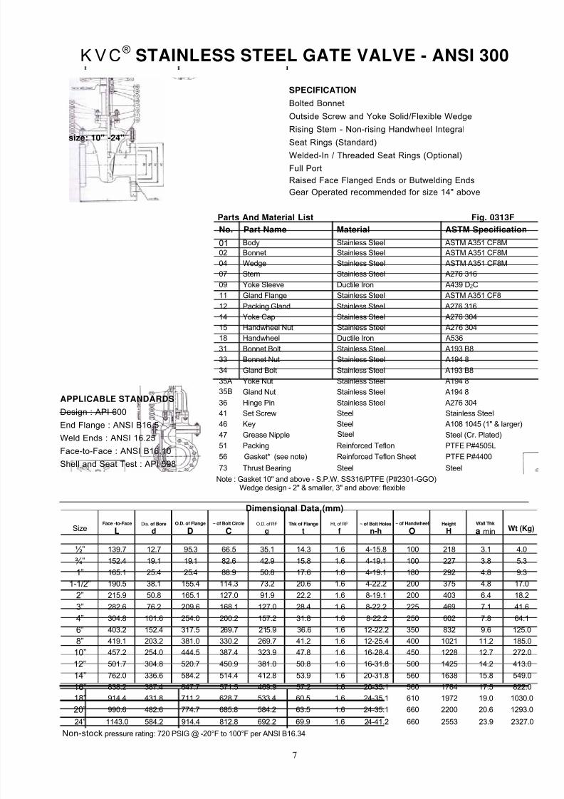
KVC® STAINLESS STEEL GATE VALVE - ANSI 300
8/2/2019 KVC - Stainless Steel Valves
http://slidepdf.com/reader/full/kvc-stainless-steel-valves 9/39
7
KVC® STAINLESS STEEL GATE VALVE - ANSI 300
Parts And Material List Fig. 0313F
No. Part Name Material ASTM Specification
01 Body Stainless Steel ASTM A351 CF8M
02 Bonnet Stainless Steel ASTM A351 CF8M
04 Wedge Stainless Steel ASTM A351 CF8M
07 Stem Stainless Steel A276 316
09 Yoke Sleeve Ductile Iron A439 DZC
11 Gland Flange Stainless Steel ASTM A351 CF8
12 Packing Gland Stainless Steel A276 316
14 Yoke Cap Stainless Steel A276 304
15 Handwheel Nut Stainless Steel A276 304
18 Handwheel Ductile Iron A536
31 Bonnet Bolt Stainless Steel A193 B8
33 Bonnet Nut Stainless Steel A194 8
34 Gland Bolt Stainless Steel A193 B8
35A Yoke Nut Stainless Steel A194 8
35B Gland Nut Stainless Steel A194 8
36 Hinge Pin Stainless Steel A276 304
41 Set Screw Steel Stainless Steel
46 Key Steel A108 1045 (1" & larger)
47 Grease Nipple Steel Steel (Cr. Plated)
51 Packing Reinforced Teflon PTFE P#4505L
56 Gasket* (see note) Reinforced Teflon Sheet PTFE P#4400
73 Thrust Bearing Steel Steel
Note : Gasket 10" and above - S.P.W. SS316/PTFE (P#2301-GGO)Wedge design - 2" & smaller, 3" and above: flexible
Dimensional Data (mm)
SizeFace -to-Face
LDia. of Bore
dO.D. of Flange
D~ of Bolt Circle
CO.D. of RF
gThk of Flange
tHt, of RF
f~ of Bolt Holes
n-h~ of Handwheel
OHeight
HWall Thk
a min Wt (Kg)
½” 139.7 12.7 95.3 66.5 35.1 14.3 1.6 4-15.8 100 218 3.1 4.0
¾” 152.4 19.1 19.1 82.6 42.9 15.8 1.6 4-19.1 100 227 3.8 5.31” 165.1 25.4 25.4 88.9 50.8 17.6 1.6 4-19.1 180 292 4.8 9.3
1-1/2” 190.5 38.1 155.4 114.3 73.2 20.6 1.6 4-22.2 200 375 4.8 17.0
2” 215.9 50.8 165.1 127.0 91.9 22.2 1.6 8-19.1 200 403 6.4 18.2
3” 282.6 76.2 209.6 168.1 127.0 28.4 1.6 8-22.2 225 469 7.1 41.6
4” 304.8 101.6 254.0 200.2 157.2 31.8 1.6 8-22.2 250 602 7.8 64.1
6” 403.2 152.4 317.5 269.7 215.9 36.6 1.6 12-22.2 350 832 9.6 125.0
8” 419.1 203.2 381.0 330.2 269.7 41.2 1.6 12-25.4 400 1021 11.2 185.0
10” 457.2 254.0 444.5 387.4 323.9 47.8 1.6 16-28.4 450 1228 12.7 272.0
12” 501.7 304.8 520.7 450.9 381.0 50.8 1.6 16-31.8 500 1425 14.2 413.0
14” 762.0 336.6 584.2 514.4 412.8 53.9 1.6 20-31.8 560 1638 15.8 549.0
16” 838.2 387.4 647.7 571.5 469.9 57.2 1.6 20-35.1 560 1784 17.5 822.0
18” 914.4 431.8 711.2 628.7 533.4 60.5 1.6 24-35.1 610 1972 19.0 1030.020” 990.6 482.6 774.7 685.8 584.2 63.5 1.6 24-35.1 660 2200 20.6 1293.0
24” 1143.0 584.2 914.4 812.8 692.2 69.9 1.6 24-41.2 660 2553 23.9 2327.0
Non-stock pressure rating: 720 PSIG @ -20°F to 100°F per ANSI B16.34
SPECIFICATION
Bolted Bonnet
Outside Screw and Yoke Solid/Flexible Wedge
Rising Stem - Non-rising Handwheel Integral
Seat Rings (Standard)
Welded-In / Threaded Seat Rings (Optional)
Full Port
Raised Face Flanged Ends or Butwelding Ends
Gear Operated recommended for size 14" above
size: 10" -24"
APPLICABLE STANDARDS
Design : API 600
End Flange : ANSI B16.5
Weld Ends : ANSI 16.25
Face-to-Face : ANSI B16.10
Shell and Seat Test : API 598
8/2/2019 KVC - Stainless Steel Valves
http://slidepdf.com/reader/full/kvc-stainless-steel-valves 10/39
8
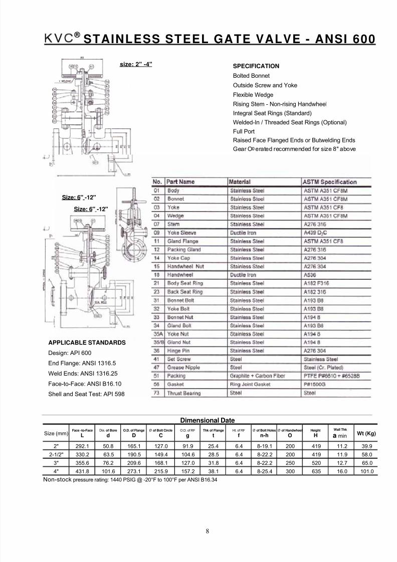
KVC ® STAINLESS STEEL GATE VALVE - ANSI 600
Dimensional Date
Size (mm)Face -to-Face
LDia. of Bore
dO.D. of Flange
DØ of Bolt Circle
CO.D. of RF
gThk of Flange
tHt. of RF
fØ of Bolt Holes
n-h
Ø of Handwheel
OHeight
H
Wall Thk
a min Wt (Kg)
2" 292.1 50.8 165.1 127.0 91.9 25.4 6.4 8-19.1 200 419 11.2 39.9
2-1/2" 330.2 63.5 190.5 149.4 104.6 28.5 6.4 8-22.2 200 419 11.9 58.0
3" 355.6 76.2 209.6 168.1 127.0 31.8 6.4 8-22.2 250 520 12.7 65.0
4" 431.8 101.6 273.1 215.9 157.2 38.1 6.4 8-25.4 300 635 16.0 101.0
Non-stock pressure rating: 1440 PSIG @ -20°F to 100°F per ANSI B16.34
SPECIFICATION
Bolted Bonnet
Outside Screw and Yoke
Flexible Wedge
Rising Stem - Non-rising Handwheel
Integral Seat Rings (Standard)
Welded-In / Threaded Seat Rings (Optional)
Full Port
Raised Face Flanged Ends or Butwelding Ends
Gear O erated recommended for size 8" above
APPLICABLE STANDARDS
Design: API 600
End Flange: ANSI 1316.5
Weld Ends: ANSI 1316.25
Face-to-Face: ANSI B16.10
Shell and Seat Test: API 598
size: 2" -4"
Size: 6" -12"
Size: 6" -12"
8/2/2019 KVC - Stainless Steel Valves
http://slidepdf.com/reader/full/kvc-stainless-steel-valves 11/39
9
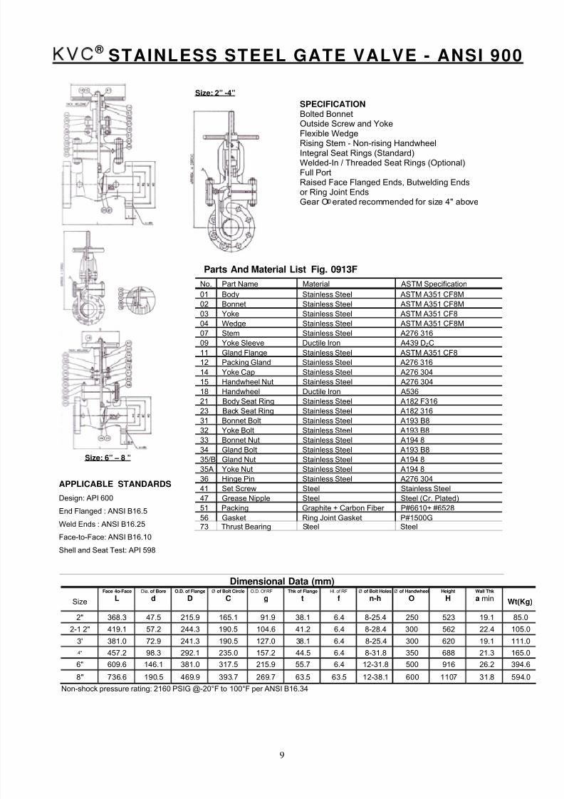
KVC ® STAINLESS STEEL GATE VALVE - ANSI 900
Parts And Material List Fig. 0913F
Dimensional Data (mm)
Size
Face 4o-Face
LDia. of Bore
dO.D. of Flange
DØ of Bolt Circle
CO.D. Of RF
gThk of Flange
tHl. of RF
fØ of Bolt Holes
n-hØ of Handwheel
OHeight
HWall Thk
a min Wt(Kg)
2" 368.3 47.5 215.9 165.1 91.9 38.1 6.4 8-25.4 250 523 19.1 85.0
2-1 2" 419.1 57.2 244.3 190.5 104.6 41.2 6.4 8-28.4 300 562 22.4 105.0
3' 381.0 72.9 241.3 190.5 127.0 38.1 6.4 8-25.4 300 620 19.1 111.0
4" 457.2 98.3 292.1 235.0 157.2 44.5 6.4 8-31.8 350 688 21.3 165.0
6" 609.6 146.1 381.0 317.5 215.9 55.7 6.4 12-31.8 500 916 26.2 394.6
8" 736.6 190.5 469.9 393.7 269.7 63.5 63.5 12-38.1 600 1107 31.8 594.0
Non-shock pressure rating: 2160 PSIG @-20°F to 100°F per ANSI B16.34
No. Part Name Material ASTM Specification
01 Body Stainless Steel ASTM A351 CF8M
02 Bonnet Stainless Steel ASTM A351 CF8M
03 Yoke Stainless Steel ASTM A351 CF8
04 Wedge Stainless Steel ASTM A351 CF8M
07 Stem Stainless Steel A276 316
09 Yoke Sleeve Ductile Iron A439 DZC
11 Gland Flange Stainless Steel ASTM A351 CF8
12 Packing Gland Stainless Steel A276 316
14 Yoke Cap Stainless Steel A276 304
15 Handwheel Nut Stainless Steel A276 304
18 Handwheel Ductile Iron A536
21 Body Seat Ring Stainless Steel A182 F316
23 Back Seat Ring Stainless Steel A182 316
31 Bonnet Bolt Stainless Steel A193 B832 Yoke Bolt Stainless Steel A193 B8
33 Bonnet Nut Stainless Steel A194 8
34 Gland Bolt Stainless Steel A193 B8
35/B Gland Nut Stainless Steel A194 8
35A Yoke Nut Stainless Steel A194 8
36 Hinge Pin Stainless Steel A276 304
41 Set Screw Steel Stainless Steel
47 Grease Nipple Steel Steel (Cr. Plated)
51 Packing Graphite + Carbon Fiber P#6610+ #6528
56 Gasket Ring Joint Gasket P#1500G73 Thrust Bearing Steel Steel
Size: 6” – 8 ”
Size: 2” -4”
SPECIFICATIONBolted BonnetOutside Screw and YokeFlexible WedgeRising Stem - Non-rising HandwheelIntegral Seat Rings (Standard)Welded-In / Threaded Seat Rings (Optional)Full PortRaised Face Flanged Ends, Butwelding Endsor Ring Joint EndsGear O erated recommended for size 4" above
APPLICABLE STANDARDS
Design: API 600
End Flanged : ANSI B16.5
Weld Ends : ANSI B16.25
Face-to-Face: ANSI B16.10
Shell and Seat Test: API 598
8/2/2019 KVC - Stainless Steel Valves
http://slidepdf.com/reader/full/kvc-stainless-steel-valves 12/39
10
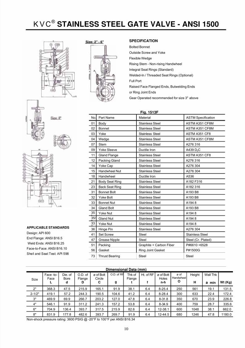
KVC® STAINLESS STEEL GATE VALVE - ANSI 1500
Size: 2" - 6"
Parts And Material List Fig. 1513F
No. Part Name Material ASTM Specification
01 Body Stainless Steel ASTM A351 CF8M
02 Bonnet Stainless Steel ASTM A351 CF8M
03 Yoke Stainless Steel ASTM A351 CF8
04 Wedge Stainless Steel ASTM A351 CF8M
07 Stem Stainless Steel A276 316
09 Yoke Sleeve Ductile Iron A439 D2C
11 Gland Flange Stainless Steel ASTM A351 CF8
12 Packing Gland Stainless Steel A276 316
14 Yoke Cap Stainless Steel A276 304
15 Handwheel Nut Stainless Steel A276 304
18 Handwheel Ductile Iron A536
21 Body Seat Ring Stainless Steel A182 F31623 Back Seat Ring Stainless Steel A182 316
31 Bonnet Bolt Stainless Steel A193 B8
32 Yoke Bolt Stainless Steel A193 B8
33 Bonnet Nut Stainless Steel A194 8
34 Gland Bolt Stainless Steel A193 B8
35 Yoke Nut Stainless Steel A194 8
35/ Gland Nut Stainless Steel A194 8
33 Yoke Nut Stainless Steel A194 8
36 Hinge Pin Stainless Steel A276 304
41 Set Screw Steel Stainless Steel
47 Grease Nipple Steel Steel (Cr. Plated)
51 Packing Graphite + Carbon Fiber P#6610 +6528
56 Gasket Ring Joint Gasket P#1500G
73 Thrust Bearing Steel Steel
Dimensional Data (mm)
Size
Face -to-Face
L
Die. of Bore
d
O.D. of Flange
D
ø of BoltCircle
C
O.D. of RF
g
Thk of Flange
t
Ht. of RF f
ø of BottHolesn-h
ø of Handwheel
O
Height
H
Wall Thk
a min Wt (Kg)
2" 368.3 47.5 215.9 165.1 91.9 38.1 6.4 8-25.4 250 561 19.1 131.5
2-1/2" 419.1 57.2 244.3 190.5 104.6 41.2 6.4 8-28.4 300 633 22.4 172.4
3" 469.9 69.9 266.7 203.2 127.0 47.8 6.4 8-31.8 350 670 23.9 226.8
4" 546.1 91.9 311.2 241.3 157.2 53.8 6.4 8-34.9 400 759 28.7 335.66" 704.9 136.4 393.7 317.5 215.9 82.6 6.4 12-38.1 600 1048 38.1 662.0
8" 831.9 177.8 482.6 393.7 269.7 91.9 6.4 12-44.5 680 1246 47.8 1180.0
Non-shock pressure rating: 3600 PSIG @ -20°F to 100°F per ANSI B16.34
APPLICABLE STANDARDS
Design: API 600
End Flange: ANSI B16.5
Weld Ends: ANSI B16.25Face-to-Face: ANSI B16.10
Shell and Seat Test: API 598
SPECIFICATION
Bolted Bonnet
Outside Screw and Yoke
Flexible Wedge
Rising Stem - Non-rising Handwheel
Integral Seat Rings (Standard)
Welded-In / Threaded Seat Rings (Optional)
Full Port
Raised Face Flanged Ends, Butwelding Ends
or Ring Joint Ends
Gear Operated recommended for size 3" above

8/2/2019 KVC - Stainless Steel Valves
http://slidepdf.com/reader/full/kvc-stainless-steel-valves 13/39
11
KVC® STAINLESS STEEL GLOBE VALVES
BODYThe body is in stainless steel. The basic dimensions, i.e.wall thickness face to face and flanges comply with therelevant API and ANSI standards. The body-to-bonnetflange is circular and the sealing surfaces for connectionto 11ne bonnet are recessed in the ANSI rating 150 and300 ser4es or may be ring joint in the higher series. Thebody wa7dard is integral seat and may be threaded for arenewable seat. Bosses may be provided for drain tapsor by pass piping.
BONNETThe bonnet is in stainless steel. It is machined to acceptthe yoke sleeve and incorporates a stuffing boxdimensioned in accordance with the API standard.
DISCThe disc is part of the trim. It is in stainless steel. It isnormally supplied of the flat, tapered or plug type or, onrequest, for the parabolic regulating type, always free torotate on the stem. Special attention is given to theseating face which is ground and lapped, for a perfectly
tight seal.
STEMThe stem is in stainless steel and is part of the trim.A ground backseat is provide to ensure a perfectlytight seal to the stuffing box when the valve is fullyopen. The stem is attached to the disc by means of a threaded ring which allows the disc to rotate. Thestem is ground to minimize friction and preventdamage to gland packing.
SEAT RING (if not integral)The ring is in stainless steel and is part of the trim.Its outer diameter is threaded and its bore is notchedto ease installation and dismantling. Specialattention is given to the seating face which is groundand lapped, for a perfectly tight seal.
YOKE SLEEVE
The yoke sleeve is made from cast aluminum,bronze, stainless steel or ductile iron having highresistance to wear and a high melting point. It isscrewed into the bonnet and properly sized towithstand the stresses which develop when openingand closing the valve.
HANDWHEELThe steel or nodular iron handwheels are wellshaped and large enough to give ease of movementwhen operating the valve, even under maximumdifferential pressure.
BONNET BUSHING (if not integral)The bonnet bushing or backseat is in forgedstainless steel and forms part of the trim. Specialattention is given to its machining and heattreatment to insure a proper seat for gland re-packing under pressure. Special attention is given tothe seating face which is ground and lapped, for aperfectly tight seal.
GLAND AND FLANGEThey are in stainless steel and are normally suppliedin two pieces. The contact surfaces between glandand gland flange have a spherical profile to permitthe gland to descend parallel to the stem even if theeyebolts are unevenly tightened.
BONNET BOLTINGBonnet studs and nuts are manufactured from alloyor stainless steel to the relevant ASTM standard.
GLAND BOLTS AND NUTSThe forged stainless steel gland bolts are of theeyebolt type which can be swing outward for ease of gland re-packing. They are fixed to the bonnet bystud bolts and nuts.
8/2/2019 KVC - Stainless Steel Valves
http://slidepdf.com/reader/full/kvc-stainless-steel-valves 14/39
12
KVC® STAINLESS STEEL GLOBE VALVE - ANSI 150
Parts And Material List Fig. 0123F
No Part Name Material ASTM
01 Body Stainless Steel ASTM A351 CF8M02 Bonnet Stainless Steel ASTM A351 CF8M
04 Disc Stainless Steel ASTM A351 CF8M
07 Stem Stainless Steel A276 316
10 Yoke Bush Ductile Iron A439 DZC
11 Gland Flange Stainless Steel ASTM A351 CF8
12 Packing Gland Stainless Steel A276 316
13 Disc Nut Stainless Steel A276 316
15 Handwheel Nut Stainless Steel A194 8
19 Handwheel Ductile Iron A536
31 Bonnet Bolt Stainless Steel A193 B8
33 Bonnet Nut Stainless Steel A194 8
34 Gland Bolt Stainless Steel A193 B8
35 Gland Nut Stainless Steel A194 8
36 Hinge Pin Stainless Steel A276 304
42 Washer Steel A167 304
51 Packing Reinforced Teflon PTFE P#4505L
56 Gasket Reinforced Teflon PTFE P#4400
Face –to-Dimensional Data (mm)Size Face -to- Die. of O.D. of ø of Bolt O.D. of RF Thk of Ht. of RF ø of Bott ø of Height Wall Thk1/2" 108.0 12.7 88.9 60.5 35.1 11.2 1.6 4-15.8 100 191 3.0 3.5
3/4" 117.5 19.1 98.6 69.9 42.9 11.2 1.6 4-15.8 100 200 3.1 4.8
1" 127.0 25.4 108.0 79.2 50.8 11.2 1.6 4-15.8 120 215 4.1 5.21-1/2" 165.1 38.1 127.0 98.6 73.2 14.3 1.6 4-15.8 200 284 4.8 12.1
2" 203.2 50.8 152.4 120.7 91.9 15.8 1.6 4-19.1 200 282 5.6 14.62-1/2" 215.9 63.5 177.8 139.7 104.6 17.6 1.6 4-19.1 250 360 5.6 24.3
3" 241.3 76.2 190.5 152.4 127.0 19.1 1.6 4-19.1 250 386 5.6 31.04" 292.1 101.6 228.6 190:5 157.2 23.9 1.6 8-19.1 300 409 6.4 45.0
6" 406.4 152.4 279.4 241.3 215.9 25.4 1.6 8-22.2 350 512 7.1 81.68" 495.3 203.2 342.9 298.5 269.7 28.4 1.6 8-22.2 400 626 8.1 137.0
10" 622.3 254.0 406.4 362.0 323.9 30.3 1.6 12-25.4 450 641 8.6 240.012" 698.5 304.8 482.6 431.8 381.0 31.8 1.6 12-25.4 500 8831 9.6 499.0
Non-shock pressure rating: 275 PSIG @ -20°F to 100°F per ANSI B16.34
SPECIFICATIONBolted Bonnet
Outside Screw and Yoke
Rising Stem - Handwheel
Integral Seat Ring - Stellited (Standard)
Welded or Threaded Seat Ring - Stellited (Optional)
Yoke Integral with Bonnet
Full Port
APPLICABLE STANDARDSDesign: ANSI B16.34End Flange: ANSI B16.5Weld Ends: ANSI B16.25
Face-to-Face: ANSI B16.10Shell and Seat Test: AP1598
Size: ½ -1”
Size: 1½ -12”
8/2/2019 KVC - Stainless Steel Valves
http://slidepdf.com/reader/full/kvc-stainless-steel-valves 15/39
13
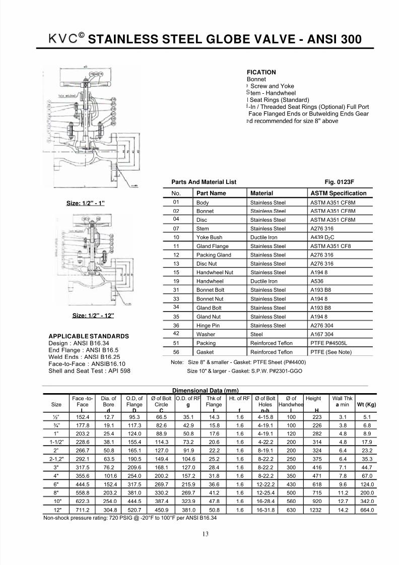
KVC © STAINLESS STEEL GLOBE VALVE - ANSI 300
Parts And Material List Fig. 0123F
No. Part Name Material ASTM Specification
01 Body Stainless Steel ASTM A351 CF8M
02 Bonnet Stainless Steel ASTM A351 CF8M
04 Disc Stainless Steel ASTM A351 CF8M
07 Stem Stainless Steel A276 316
10 Yoke Bush Ductile Iron A439 DZC
11 Gland Flange Stainless Steel ASTM A351 CF8
12 Packing Gland Stainless Steel A276 316
13 Disc Nut Stainless Steel A276 316
15 Handwheel Nut Stainless Steel A194 8
19 Handwheel Ductile Iron A536
31 Bonnet Bolt Stainless Steel A193 B8
33 Bonnet Nut Stainless Steel A194 8
34 Gland Bolt Stainless Steel A193 B8
35 Gland Nut Stainless Steel A194 8
36 Hinge Pin Stainless Steel A276 304
42 Washer Steel A167 304
51 Packing Reinforced Teflon PTFE P#4505L
56 Gasket Reinforced Teflon PTFE (See Note)
Note: Size 8" & smaller - Gasket: PTFE Sheet (P#4400)
Size 10" & larger - Gasket: S.P.W. P#2301-GGO
Dimensional Data (mm)
SizeFace -to-
FaceL
Dia. of Bore
d
O.D, of Flange
D
Ø of BoltCircle
C
O.D. of RFg
Thk of Flange
t
Ht. of RF f
Ø of BoltHolesn-h
Ø of Handwhee
l
Height
H
Wall Thka min Wt (Kg)
½” 152.4 12.7 95.3 66.5 35.1 14.3 1.6 4-15.8 100 223 3.1 5.1
¾” 177.8 19.1 117.3 82.6 42.9 15.8 1.6 4-19.1 100 226 3.8 6.8
1” 203.2 25.4 124.0 88.9 50.8 17.6 1.6 4-19.1 120 282 4.8 8.9
1-1/2” 228.6 38.1 155.4 114.3 73.2 20.6 1.6 4-22.2 200 314 4.8 17.9
2” 266.7 50.8 165.1 127.0 91.9 22.2 1.6 8-19.1 200 324 6.4 23.2
2-1,2" 292.1 63.5 190.5 149.4 104.6 25.2 1.6 8-22.2 250 375 6.4 35.3
3" 317.5 76.2 209.6 168.1 127.0 28.4 1.6 8-22.2 300 416 7.1 44.7
4" 355.6 101.6 254.0 200.2 157.2 31.8 1.6 8-22.2 350 471 7.8 67.0
6" 444.5 152.4 317.5 269.7 215.9 36.6 1.6 12-22.2 430 618 9.6 124.0
8" 558.8 203.2 381.0 330.2 269.7 41.2 1.6 12-25.4 500 715 11.2 200.010" 622.3 254.0 444.5 387.4 323.9 47.8 1.6 16-28.4 560 920 12.7 342.0
12" 711.2 304.8 520.7 450.9 381.0 50.8 1.6 16-31.8 630 1232 14.2 664.0
Non-shock pressure rating: 720 PSIG @ -20°F to 100°F per ANSI B16.34
FICATIONBonnet
Screw and Yoketem - Handwheel
l Seat Rings (Standard)-In / Threaded Seat Rings (Optional) Full PortFace Flanged Ends or Butwelding Ends Gear d recommended for size 8" above
Size: 1/2" - 1"
Size: 1/2" - 12"
APPLICABLE STANDARDSDesign : ANSI B16.34End Flange : ANSI B16.5Weld Ends : ANSI B16.25Face-to-Face : ANSIB16.10Shell and Seat Test : API 598

8/2/2019 KVC - Stainless Steel Valves
http://slidepdf.com/reader/full/kvc-stainless-steel-valves 16/39
14
KVC © STAINLESS STEEL GLOBE VALVE - ANSI 600
en
APPLICABLE STANDARDS Design:
Parts And Material List Fig. 0623F
No. Part Name Material ASTM Specification
01 Body Stainless Steel ASTM A351 CF8M
02 Bonnet Stainless Steel ASTM A351 CF8M
04 Disc Stainless Steel A276 316
07 Stem Stainless Steel A276 316
10 Yoke Bush Ductile Iron A439 DZC
11 Gland Flange Stainless Steel ASTM A351 CF8
12 Packing Gland Stainless Steel A276 316
13 Disc Nut Stainless Steel A276 316
15 Handwheel Nut Stainless Steel A194 8
19 Handwheel Ductile Iron A536
21 Body Seat Ring Stainless Steel A182 F316
23 Back Seat Ring Stainless Steel A182 316
31 Bonnet Bolt Stainless Steel A193 B8
33 Bonnet Nut Stainless Steel A194 8
34 Gland Bolt Stainless Steel A193 B8
35 Gland Nut Stainless Steel A194 8
36 Hinge Pin Stainless Steel A276 304
42 Washer Steel A167 304
51 Packing Graphite + Carbon Fiber P#6610 +#652856 Gasket Ring Joint Gasket P#1500G
Dimensional Data (mm)
SizeFace -to-Face
LDia, of Bore
dO.D. of Flange
Do of Bolt Circle
C
O.D. of RF
gThk of Flange
tHt. of RF
f+of Bott Holes
n-h~ of Handwheel
OHeight
H
Wall Thk
a min Wt (Kg)
2" 292.1 50.8 165.1 127.0 91.9 25.4 6.4 8-19.1 250 392 11.2 37.2
3" 355.6 76.2 209.6 168.1 127.0 31.8 6.4 8-22.2 300 478 12.7 65.0
4" 431.8 101.6 273.1 215.9 157.2 38.1 6.4 8-25.4 350 530 16.0 96.0
6" 558.8 152.4 355.6 292.1 215.9 47.8 6.4 12-28.4 500 675 19.1 269.0
8" 660.4 199.9 419.1 349.3 269.7 55.7 6.4 12-31.8 560 721 25.4 400.0
10" 787.4 247.7 508.0 431.8 323.9 63.5 6.4 16-35.1 630 972 28.7 692.0
12" 838.2 298.5 558.8 489.0 381.0 66.6 6.4 20-35.1 710 1074 31.8 907.0
SPECIFICATIONBolted BonnetOutside Screw and YokeRising Stem - Handwheel
Integral Seat Rings (Standard)Welded-In / Threaded Seat Rings (Optional)Full Port Raised Face Flanged Ends or Butwelding Endsor Ring Joint EndsGear Operated recommended for size 4" above
Size : 2” to 6”
APPLICABLE STANDARDS
Design : ANSI B16.34End Flange : ANSI B16.5Weld Ends : ANSI B16.25
Face-to-Face : ANSI B16.10Shell and Seat Test : API 598
Non-shock pressure rating: 1440 PSIG @ -20°F to 1 00°F per ANSI 1316.34
8/2/2019 KVC - Stainless Steel Valves
http://slidepdf.com/reader/full/kvc-stainless-steel-valves 17/39
15
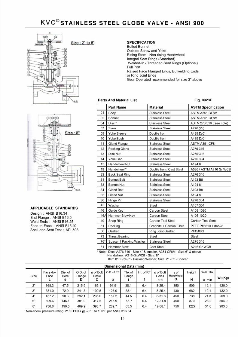
KVC ©
STAINLESS STEEL GLOBE VALVE - ANSI 900
Parts And Material List Fig. 0923F
Part Name Material ASTM Specification
01 Body Stainless Steel ASTM A351 CF8M
02 Bonnet Stainless Steel ASTM A351 CF8M04 Disc * Stainless Steel ASTM 276 316 (`see note)
07 Stem Stainless Steel A276 316
09 Yoke Sleeve Ductile Iron A439 DZC
10 Yoke Bush Ductile Iron A439 D2C
11 Gland Flange Stainless Steel ASTM A351 CF8
12 Packing Gland Stainless Steel A276 316
13 Disc Nut Stainless Steel A276 316
14 Yoke Cap Stainless Steel A276 304
15 Handwheel Nut Stainless Steel A194 8
19 Handwheel * Ductile Iron / Cast Steel A536 / ASTM A216 Gr.WCB
23 Back Seat Ring Stainless Steel A276 316
31 Bonnet Bolt Stainless Steel A193 B8
33 Bonnet Nut Stainless Steel A194 8
34 Gland Bolt Stainless Steel A193 B8
35 Gland Nut Stainless Steel A194 8
36 Hinge Pin Stainless Steel A276 304
42 Washer Steel A167 304
46 Guide Key Carbon Steel A108 1020
46A Hammer Blow Key Carbon Steel A108 1020
49 Snap Ring Carbon Tool Steel Carbon Tool Steel
51 Packing Graphite + Carbon Fiber PTFE P#6610 + #6528
56 Gasket Ring Joint Gasket P#1500G
73 Thrust Bearing Steel Steel76* Spacer 1 Packing Washer Stainless Steel A276 316
81 Hammer Blow Cast Steel A216 Gr.WCB
* Note: Disc: A276 316 - Size 4" & smaller, A351 CF8M - Size 6" & aboveHandwheel: A216 Gr.WCB - Size: 8"Item 81: Size 8" - Packing Washer, Size: 2" - 6" - Spacer
Dimensional Data (mm)
SizeFace -to-
FaceL
Die. of Bore
d
O.D. of Flange
D
ø of BoltCircle
C
O.D. of RF
g
Thk of Flange
t
Ht. of RF f
ø of BottHolesn-h
ø of Handwheel
O
Height
H
Wall Thk
a minWt (Kg)
2” 368.3 47.5 215.9 165.1 91.9 38.1 6.4 8-25.4 350 509 19.1 120.0
3” 381.0 72.9 241.3 190.5 127.0 38.1 6.4 8-25.4 430 682 19.1 132.0
4” 457.2 98.3 292.1 235.0 157.2 44.5 6.4 8-31.8 450 738 21.3 209.0
6” 609.6 146.1 381.0 317.5 215.9 55.7 6.4 12-31.8 450 870 26.2 504.0
8” 736.6 190.5 469.9 393.7 269.7 63.5 6.4 12-38.1 750 1227 31.8 903.0
Non-shock pressure rating: 2160 PSIG @ -20°F to 100°F per ANSI B16.34
SPECIFICATIONBolted BonnetOutside Screw and YokeRising Stem - Non-rising Handwheel
Integral Seat Rings (Standard)Welded-In / Threaded Seat Rings (Optional)
Full PortRaised Face Flanged Ends, Butwelding Endsor Ring Joint EndsGear Operated recommended for size 3" above
APPLICABLE STANDARDS
Design : ANSI B16.34End Flange : ANSI B16.5Weld Ends : ANSI B16.25Face-to-Face : ANSI B16.10Shell and Seat Test : API 598
8/2/2019 KVC - Stainless Steel Valves
http://slidepdf.com/reader/full/kvc-stainless-steel-valves 18/39
16
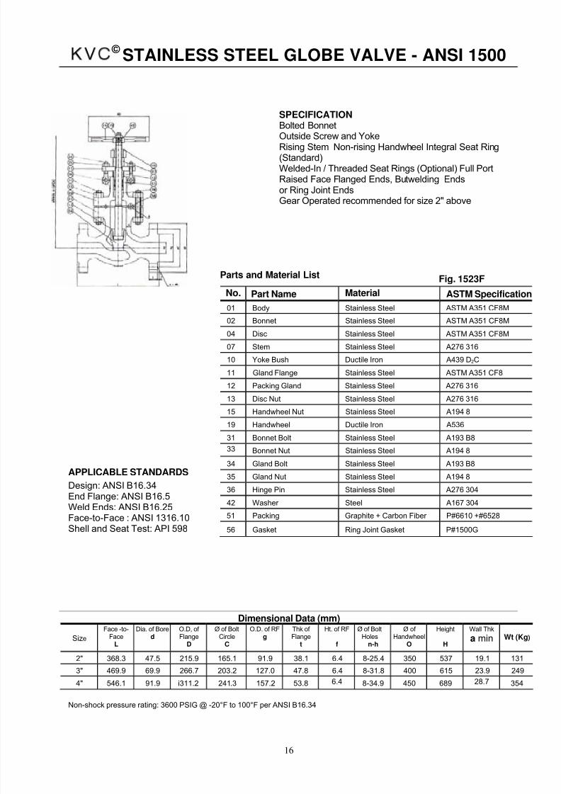
KVC © STAINLESS STEEL GLOBE VALVE - ANSI 1500
No. Part Name Material ASTM Specification
01 Body Stainless Steel ASTM A351 CF8M
02 Bonnet Stainless Steel ASTM A351 CF8M
04 Disc Stainless Steel ASTM A351 CF8M
07 Stem Stainless Steel A276 316
10 Yoke Bush Ductile Iron A439 D2C
11 Gland Flange Stainless Steel ASTM A351 CF8
12 Packing Gland Stainless Steel A276 316
13 Disc Nut Stainless Steel A276 316
15 Handwheel Nut Stainless Steel A194 8
19 Handwheel Ductile Iron A536
31 Bonnet Bolt Stainless Steel A193 B8
33 Bonnet Nut Stainless Steel A194 8
34 Gland Bolt Stainless Steel A193 B8
35 Gland Nut Stainless Steel A194 8
36 Hinge Pin Stainless Steel A276 304
42 Washer Steel A167 304
51 Packing Graphite + Carbon Fiber P#6610 +#6528
56 Gasket Ring Joint Gasket P#1500G
Dimensional Data (mm)
Size
Face -to-Face
L
Dia. of Bored
O.D, of Flange
D
Ø of BoltCircle
C
O.D. of RFg
Thk of Flange
t
Ht. of RF
f
Ø of BoltHoles
n-h
Ø of Handwheel
O
Height
H
Wall Thk
a min Wt (Kg)
2" 368.3 47.5 215.9 165.1 91.9 38.1 6.4 8-25.4 350 537 19.1 131
3" 469.9 69.9 266.7 203.2 127.0 47.8 6.4 8-31.8 400 615 23.9 249
4" 546.1 91.9 i311.2 241.3 157.2 53.8 6.4 8-34.9 450 689 28.7 354
Non-shock pressure rating: 3600 PSIG @ -20°F to 100°F per ANSI B16.34
SPECIFICATIONBolted Bonnet
Outside Screw and YokeRising Stem Non-rising Handwheel Integral Seat Ring(Standard)Welded-In / Threaded Seat Rings (Optional) Full PortRaised Face Flanged Ends, Butwelding Endsor Ring Joint EndsGear Operated recommended for size 2" above
APPLICABLE STANDARDS
Design: ANSI B16.34End Flange: ANSI B16.5Weld Ends: ANSI B16.25Face-to-Face : ANSI 1316.10Shell and Seat Test: API 598
Parts and Material List Fig. 1523F
8/2/2019 KVC - Stainless Steel Valves
http://slidepdf.com/reader/full/kvc-stainless-steel-valves 19/39
17
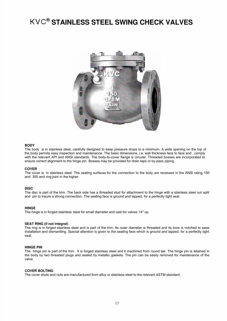
KVC ® STAINLESS STEEL SWING CHECK VALVES
BODYThe body is in stainless steel, carefully designed to keep pressure drops to a minimum. A wide opening on the top of the body permits easy inspection and maintenance. The basic dimensions, i.e. wall thickness face to face and . complywith the relevant API and ANSI standards. The body-to-cover flange is circular. Threaded bosses are incorporated toensure correct alignment to the hinge pin. Bosses may be provided for drain taps or by-pass piping.
COVERThe cover is in stainless steel. The sealing surfaces for the connection to the body are recessed in the ANSI rating 150and 300 and ring joint in the higher.
DISCThe disc is part of the trim. The back side has a threaded stud for attachment to the hinge with a stainless steel nut splitand pin to insure a strong connection. The seating face is ground and lapped, for a perfectly tight seal.
HINGEThe hinge is in forged stainless steel for small diameter and cast for valves 14" up.
SEAT RING (if not integral)The ring is in forged stainless steel and is part of the trim. Its outer diameter is threaded and its bore is notched to easeinstallation and dismantling. Special attention is given to the seating face which is ground and lapped, for a perfectly tightseal.
HINGE PINThe hinge pin is part of the trim. It is forged stainless steel and it machined from round bar. The hinge pin is retained inthe body by two threaded plugs and sealed by metallic gaskets. The pin can be easily removed for maintenance of thevalve.
COVER BOLTINGThe cover studs and nuts are manufactured from alloy or stainless steel to the relevant ASTM standard.
8/2/2019 KVC - Stainless Steel Valves
http://slidepdf.com/reader/full/kvc-stainless-steel-valves 20/39
18
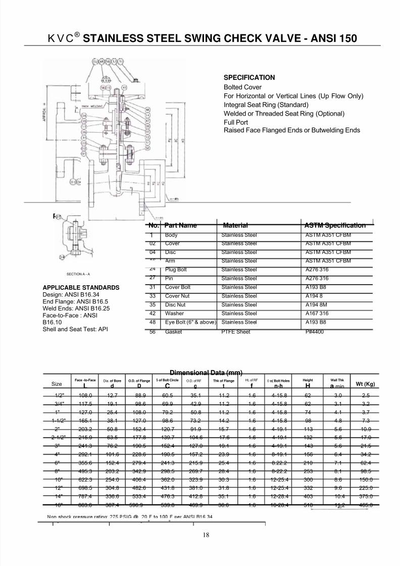
K VC® STAINLESS STEEL SWING CHECK VALVE - ANSI 150
Parts And Material List
No. Part Name Material ASTM Specification
1 Body Stainless Steel ASTM A351 CFBM
02 Cover Stainless Steel ASTM A351 CFBM
04 Disc Stainless Steel ASTM A351 CFBM
16 Arm Stainless Steel ASTM A351 CFBM 24 Plug Bolt Stainless Steel A276 316
27 Pin Stainless Steel A276 316
31 Cover Bolt Stainless Steel A193 B8
33 Cover Nut Stainless Steel A194 835 Disc Nut Stainless Steel A194 8M
42 Washer Stainless Steel A167 316
48 Eye Bolt (6" & above) Stainless Steel A193 B8
56 Gasket PTFE Sheet P#4400
Dimensional Data (mm)
SizeFace -to-Face
LDia. of Bore
dO.D. of Flange
D
$ of Bolt Circle
CO.D. of RF
gThk of Flange
tHt, of RF
f0 o( Bolt Holes
n-hHeight
HWall Thk
a min Wt (Kg)
1/2" 108.0 12.7 88.9 60.5 35.1 11.2 1.6 4-15.8 62 3.0 2.53/4" 117.5 19.1 98.6 69.9 42.9 11.2 1.6 4-15.8 62 3.1 3.2
1" 127.0 25.4 108.0 79.2 50.8 11.2 1.6 4-15.8 74 4.1 3.7
1-1/2" 165.1 38.1 127.0 98.6 73.2 14.2 1.6 4-15.8 98 4.8 7.3
2" 203.2 50.8 152.4 120.7 91.9 15.7 1.6 4-19.1 113 5.6 10.9
2-1/2" 215.9 63.5 177.8 139.7 104.6 17.6 1.6 4-19.1 132 5.6 17.0
3" 241.3 76.2 190.5 152.4 127.0 19.1 1.6 4-19.1 143 5.6 21.5
4" 292.1 101.6 228.6 190.5 157.2 23.9 1.6 8-19.1 156 6.4 34.2
6" 355.6 152.4 279.4 241.3 215.9 25.4 1.6 8.22.2 210 7.1 62.4
8" 495.3 203.2 342.9 298.5 269.7 28.4 1.6 8-22.2 253 8.1 98.5
10" 622.3 254.0 406.4 362.0 323.9 30.3 1.6 12-25.4 300 8.6 150.0
12" 698.5 304.8 482.6 431.8 381.0 31.8 1.6 12-25.4 332 9.6 225.0
14" 787.4 336.6 533.4 476.3 412.8 35.1 1.6 12-28.4 403 10.4 375.0
16" 863.6 387.4 596.9 539.8 469.9 36.6 1.6 16-28.4 510 11.2 465.0
Ą
SPECIFICATION
Bolted Cover
For Horizontal or Vertical Lines (Up Flow Only)Integral Seat Ring (Standard)
Welded or Threaded Seat Ring (Optional)
Full PortRaised Face Flanged Ends or Butwelding Ends
- - ° °
APPLICABLE STANDARDS
Design: ANSI B16.34End Flange: ANSI B16.5Weld Ends: ANSI B16.25Face-to-Face : ANSIB16.10Shell and Seat Test: API
SECTION A - A

8/2/2019 KVC - Stainless Steel Valves
http://slidepdf.com/reader/full/kvc-stainless-steel-valves 21/39
19
APPLICABLE STANDARDS
Design : ANSI B16.34
End Flange : ANSI B16.5
Weld Ends : ANSI B16.25
Face-to-Face : ANSI B16.10
Shell and Seat Test : API 598
KVC ® STAINLESS STEEL SWING CHECK VALVE - ANSI 300
Parts And Material List Fig.0333F
No. Part Name Material ASTM Specification
01 Body Stainless Steel ASTM A351 CF8M
02 Cover Stainless Steel ASTM A351 CF8M
04 Disc Stainless Steel ASTM A351 CF8M
16 Arm Stainless Steel ASTM A351 CF8M
24 Plug Bolt Stainless Steel A276 316
27 Pin Stainless Steel A276 316
31 Cover Bolt Stainless Steel A193 B8
33 Cover Nut Stainless Steel A194 8
35 Disc Nut Stainless Steel A194 8M
42 Washer Stainless Steel A167 316
48 Eye Bolt (6" & above) Stainless Steel A193 B8
56 Gasket PTFE Sheet See Note
Note : Size 8" & smaller: PTFE Sheet P#4400. Size: 10" & Larger: S.P.W. P#2301-GGO
Parts And Material List
Size
Face -to-Face
L
Dia, of Bore
d
O.D. of Flange
Do of Bolt Circle
C
O.D. of RF
g
Thk of Flange
t
Ht. of RF
f
+of Bott Holes
n-h
Height
H
Wall Thk
a min Wt (Kg)
1-1/2” 241.3 38.1 155.4 114.3 73.2 20.6 1.6 4-22.2 122 4.8 11.3
2” 266.7 50.8 165.1 127.0 91.9 22.2 1.6 8-19.1 136 6.4 16.4
2-1/2” 292.1 63.5 190.5 149.4 104.6 25.4 1.6 8-22.2 142 6.4 24.0
3 " 317.5 76.2 209.6 168.1 127.0 28.5 1.6 8-22.2 163 7.1 35.3
4” 355.6 101.6 254.0 200.2 157.2 31.8 1.6 8-22.2 194 7.8 50.0
6” 444.5 152.4 317.5 269.7 215.9 36.6 1.6 12-22.2 243 9.6 93.5
8” 533,4 203.2 381.0 330.2 269.7 41.2 1.6 12-25.4 298 11.2 153.0
10” 622.3 254.0 444.5 387.4 323.9 47.8 1.6 16-28.4 327 12.7 230.0
12” 711.2 304.8 520.7 450.9 381.0 50.8 1.6 16-31.8 372 14.2 326.0
14” 838.2 336.6 584.2 514.4 412.8 53.9 1.6 20-31.8 437 15.8 721.0
16” 863.6 387.4 647.7 571.5 469.9 57.2 1.6 20-35.1 480 17.5 902.0
18” 977.9 431.8 711.2 628.7 533.4 60.5 1.6 24-35.1 585 19.0 1002.0
Non-shock pressure rating : 720 PSIG @-200F to 100
0F per ANSI B16.34
SPECIFICATION
Bolted Cover For Horizontal or Vertical Lines (Up Flow Only)
Integral Seat Ring (Standard)
Welded or Threaded Seat Ring (Optional)
Full PortRaised Face Flanged Ends or Butwelding Ends

8/2/2019 KVC - Stainless Steel Valves
http://slidepdf.com/reader/full/kvc-stainless-steel-valves 22/39
20
KVC ® STAINLESS STEEL SWING CHECK VALVE - ANSI 600
Parts And Material List Fig. 0633F
No. Part Name Material ASTM Specification
01 Body Stainless Steel ASTM A351
02 Cover Stainless Steel ASTM A351
04 Disc Stainless Steel ASTM A351
16 Arm Stainless Steel ASTM A351
24 Plug Bolt Stainless Steel A276 316
27 Pin Stainless Steel A276 316
31 Cover Bolt Stainless Steel A193 B8
33 Cover Nut Stainless Steel A194 8
35 Disc Nut Stainless Steel A194 8M
42 Washer Stainless Steel A167 316
` 48 Eye Bolt (4" & above) Stainless Steel A193 B8
56 Gasket Ring Joint P#1500G
Dimensional Data (mm)
SizeFace -to-Face
LDia, of Bore
dO.D. of Flange
Do of Bolt Circle
C
O.D. of RF
gThk of Flange
tHt. of RF
f+of Bott Holes
n-hHeight
HWall Thk
a min Wt (Kg)
2" 292.1 50.8 165.1 127.0 91.9 25.4 6.4 8-19.1 187 11.2 12.7
3" 355.6 76.2 209.6 168.1 127.0 31.8 6.4 8-22.2 210 12.7 54.0
4" 431.8 101.6 273.1 215.9 157.2 38.1 6.4 8-25.4 256 16.0 106.6
6" 558.8 152.4 355.6 292.1 215.9 47.8 6.4 12-28.4 329 19.1 160.0
8" 660.4 199.9 419.1 349.3 269-7 55.7 6.4 12-31.8 363 25.4 276.0
10" 787.4 247.7 508.0 431.8 323.9 63.5 6.4 16-35.1 464 28.7 414.0
APPLICABLE STANDARDSDesign: ANSI B16.34End Flange: ANSI B16.5Weld Ends: ANSI B16.25Face-to-Face: ANSI B16.10Shell and Seat Test: API 598
SPECIFICATION
Bolted Cover For Horizontal or Vertical Lines (Up Flow Only)
Integral Seat Ring (Standard)
Welded or Threaded Seat Ring Optional)
Full PortRaised Face Flanged Ends or Butwelding Ends
Non-shock pressure rating: 1440 PSIG @ -20°F to 100°F per ANSI B16.34

8/2/2019 KVC - Stainless Steel Valves
http://slidepdf.com/reader/full/kvc-stainless-steel-valves 23/39
21
KVC ® STAINLESS STEEL SWING CHECK VALVE - ANSI 900
Parts And Material List FIG. 0933F
No. Part Name Material ASTM Specification
01 Body Stainless Steel ASTM A351 CF8M
02 Cover Stainless Steel ASTM A351 CF8M
04 Disc Stainless Steel ASTM A351 CF8M
16 Arm Stainless Steel ASTM A351 CF8M
24 Plug Bolt Stainless Steel A276 316
25 Plug Gasket Graphite + Carbon Filler P#6610
27 Pin Stainless Steel A276 316
31 Cover Bolt Stainless Steel A193 B8
33 Cover Nut Stainless Steel A194 8
35 Disc Nut Stainless Steel A194 8M
42 Washer Stainless Steel A167 316
42A Plug Washer Stainless Steel A276 316
48 Eye Bolt (3" & Stainless Steel A193 B8
Dimensional Data (mm)
SizeFace -to-Face
LDia. of Bore
dO.D. of Flange
D~ of BoR Circle
CO.D. of RF
gThk of Flange
tHt. of RF
f0 of Bolt Holes
n-hHeight
H
Wall Thk
a min Wt (Kg)
2” 368.3 47.5 215.9 165.1 91.9 38.1 6.4 8-25.4 223 19.1 73.0
3” 381.0 72.9 241.3 190.5 127.0 38.1 6.4 8-25.4 255 19.1 88.0
4” 457.2 98.3 292.1 235.0 157.2 44.5 6.4 8-31.8 295 21.3 181.0
6” 609.6 146.1 381.0 317.5 215.9 55.7 6.4 12-31.8 345 26.2 313.0
8” 736.6 190.5 469.9 393.7 269.7 63.5 6.4 12-38.1 415 31.8 467.0
SPECIFICATION
Bolted Cover For Horizontal or Vertical Lines (Up Flow Only) Integral
Seat Ring (Standard)
Welded or Threaded Seat Ring (Optional) Full
Port
Raised Face Flanged Ends, Butwelding Ends or
Ring Joint Ends
Non-shock pressure rating: 2160 PSIG @ -20°F to 100°F per ANSI B16.34
APPLICABLE STANDATDSDesign : ANSI B16.34End Flange : ANSI B16.5Weld Ends : ANSI B16.25Face-to-Face : ANSI B16.10Shell and Seat Test : API 598

8/2/2019 KVC - Stainless Steel Valves
http://slidepdf.com/reader/full/kvc-stainless-steel-valves 24/39
22
KVC ® STAINLESS STEEL SWING CHECK VALVE - ANSI 1500
Parts And Material Fig. 1533F
No. Part Name Material ASTM Specification
01 Body Stainless Steel ASTM A351 CF8M
02 Cover Stainless Steel ASTM A351 CF8M
04 Disc Stainless Steel ASTM A351 CF8M
16 Arm Stainless Steel ASTM A351 CF8M
24 Plug Bolt Stainless Steel A276 316
25 Plug Gasket Graphite + Carbon Filler P#6610
27 Pin Stainless Steel A276 316
31 Cover Bolt Stainless Steel A193 B8
33 Cover Nut Stainless Steel A194 8
35 Disc Nut Stainless Steel A194 8M
42 Washer Stainless Steel A167 316
42A Plug Washer Stainless Steel A276 316
48 Eye Bolt (4" & above) Stainless Steel A193 B8
56 Gasket Ring Joint P#1500G
Dimensional Data (mm)
SizeFace -to-Face
LDia. of Bore
dO.D. of Flange
D$ of Bolt Circle
CO,D, of RF
gThk of Flange
tHt. of RF
f
~ of Bolt Holes
n-hHeight
H
Wall Thk
a Min Wt (Kg)
2" 368.3 47.5 215.9 165.1 91.9 38.1 6.4 8-25.4 223 19.1 122
2-1/2" 419.1 57.2 244.3 190.5 104.6 41.2 6.4 8-28.4 265 22.4 167
3" 469.9 69.9 266.7 203.2 127.0 47.8 6.4 8-31.8 325 23.9 195
4" 546.1 91.9 311.2 241.3 157.2 53.8 6.4 8-34.9 350 28.7 290
6" 704.9 136.4 393.7 317.5 215.9 82.6 6.4 12-38.1 370 38.1 430
8" 831.9 177.8 482.6 393.7 269.7 91.9 6.4 12-44.5 405 47.8 675
SPECIFICATION
Bolted Cover
For Horizontal or Vertical Lines (Up Flow Only) Integral Seat
Ring (Standard)Welded or Threaded Seat Ring (Optional)
Full Port
Raised Face Flanged Ends, Butwelding Ends
or Rin Joint Ends
Non-shock pressure rating: 3600 PS IG @ -20°F to 100°F per ANSI B16.34
APPLICABLE STANDARDS
Design: ANSI B16.34
End Flange: ANSI B16.5
Weld Ends: ANSI B16.25
Face-to-Face: ANSI B16.10
Shell and Seat Test: API 598
8/2/2019 KVC - Stainless Steel Valves
http://slidepdf.com/reader/full/kvc-stainless-steel-valves 25/39
23
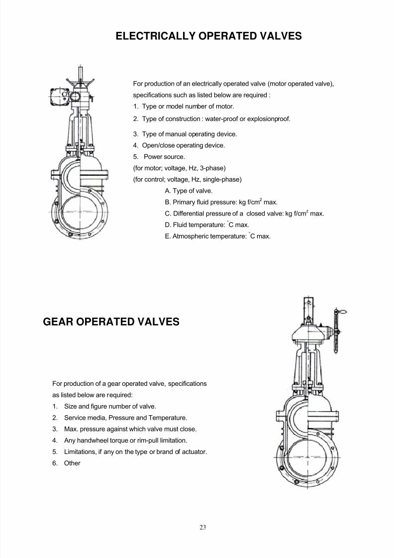
ELECTRICALLY OPERATED VALVES
For production of an electrically operated valve (motor operated valve),
specifications such as listed below are required :1. Type or model number of motor.
2. Type of construction : water-proof or explosionproof.
3. Type of manual operating device.
4. Open/close operating device.
5. Power source.
(for motor; voltage, Hz, 3-phase)
(for control; voltage, Hz, single-phase)
A. Type of valve.
B. Primary fluid pressure: kg f/cm2
max.
C. Differential pressure of a closed valve: kg f/cmz
max.
D. Fluid temperature:°C max.
E. Atmospheric temperature:°C max.
GEAR OPERATED VALVES
For production of a gear operated valve, specifications
as listed below are required:
1. Size and figure number of valve.
2. Service media, Pressure and Temperature.
3. Max. pressure against which valve must close.
4. Any handwheel torque or rim-pull limitation.
5. Limitations, if any on the type or brand of actuator.
6. Other

8/2/2019 KVC - Stainless Steel Valves
http://slidepdf.com/reader/full/kvc-stainless-steel-valves 26/39
24
W E L D I N G E N D D E T A I L S
Compound Bevel Connection Pipe Wall Thickness Connection Pipe Wall Thickness
Larger than 7/8" size 7/8" ans smaller size
A = Outside diameter of matching pipe, wrought or fabricated componentB = Nominal inside diameter t = Min. wall thickness
"A" Dimensions reference to ANSI 1316.25
"B" Dimensions reference to ANSI B36.10
mm 15 20 25 40 50 65 80 100 150 200 250 300 350 400 450 500 600Valve
nominalsize in 1/2 3/4 1 1-1/2 2 2-1/2 3 4 6 8 10 12 14 16 18 20 24
+ 0Tolerenceon A(mm) -0.8
Tolerance
on B(mm) ±0.8 1.6 ±3.2-1.6
t m i n
2
t m i n
2

8/2/2019 KVC - Stainless Steel Valves
http://slidepdf.com/reader/full/kvc-stainless-steel-valves 27/39
25
REFERENCE STANDARDS AND SPECIFICATION
KVCx valves are offered to meet the following Codes and Standards : Valves to BS Standard DIN Standardas well as GOST Standard are available upon request.
ANSI Standards - American National Standards Institute
B1.1 Unified Screw ThreadsB1.5 Acme Screw ThreadsB1.8 Stub Acme Screw ThreadsB1.12 Class 5 Interference - Fit ThreadB2.1 Pipe Threads (Except Dryseal)B16.5 Steel Pipe Flanges, and Flanged FittingsB16.10 Face-to-Face and End-to-End Dimensions of Ferrous ValvesB16.11 Forged Steel Fittings, Socket Welding and ThreadedB16.20 Ring-Joint Gaskets and Grooves for Steel Pipe FlangesB16.21 Non-metallic Gaskets for Pipe FlangesB16.25 Buttwelding EndsB16.34 Steel Valves
B18.2.2 Square and Hex NutsB31.1.0 Power PipingB31.2 Fuel Gas PipingB31.3 Petroleum Refinery PipingB31.4 Liquid Petroleum Transportation Piping SystemsB31.5 Refrigeration Piping SystemsB31.6 Chemical Process PipingB31.7 Nuclear Power PipingB31.8 Gas Transmission and Distribution Piping SystemsB36.10 Wrought-Steel and Wrought-Iron Pipe
API Standards - American Petroleum Institute
6A Specification for Wellhead Equipment6D Specification for Pipeline Valves597 Steel Venturi Gate Valves598 Valve Inspection and Test600 Steel Gate Valves, Flanged or Buttwelding Ends603 150-Lb, Light-Wall, Corrosion-Resistant Gate Valve for Refinery Use605 Large Diameter Carbon Steel Flanges
ASTM Standards - American Society for Testing and Materials
MSS Standard Practices - Manufacturers Standarisation Society of the Valve and Fittings Industry
SP-6 Finishes-for Contract Faces of Connection End Flanges of Ferrous Valves and FittingsSP-9 MSS Spot-Facing StandardSP-25 MSS Standard Making System for Valves, Fittings, Flanges and UnionsSP-42 MSS 150Lb Corrosion Resistant Cast Flanged ValvesSP-44 MSS Steel Pipe Line FlangesSP-45 MSS Bypass and Drain Connection StandardSP-53 Quality Standard for Steel Castings, Dry Particle Magnetic Inspection MethodSP-54 Quality Standard for Steel Castings, Radiographic Inspection MethodSP-55 Quality Standard for Steel Castings, Visual MethodSP-61 Hydrostatic Testing of Steel Valves

8/2/2019 KVC - Stainless Steel Valves
http://slidepdf.com/reader/full/kvc-stainless-steel-valves 28/39
26
COMPARISON LIST FOR CASTINGS AND FORGINGS
Castings ForgingsGeneral Classification
ASTM JIS BS ASTM JIS BS
18Cr-8Ni(C 0.03) A351 - CF3 - - - F304L - SUS28 -
18Cr-8Ni(C 0.08) - CFS G512 - SCS13 - - F304 - SUS27 1503 - 801
18Cr-8Ni(C 0.10) - 1504 -801 - F304H - -
Mr-8Ni-2Mo(C 0.03) A351 - CF3M G512 - SCS16 - - F316L G4303 -SUS33B -
18Cr-8Ni-2Mo(C 0.08) - CFSM - SCS14 1632 - GRC - F316 -SUS32B 1503- 845B
18Cr-8N i-2Mo(C 0.10) - - - - 316H - -
18Cr-8Ni-Ti(C 0.08) - - - - F321 G4303 - SU529 -
Mr-8Ni-Ti(C 0.10) - - 1504 - 821 Ti - - F321 H 1503 - 821Ti
18Cr-8Ni-Cb(C 0.08) A351 - CF8C - - - F347 G4303 - SUS43B - 821 Nb
18Cr-8Ni-Cb(C 0.10) - - 1504 - 821 Nb - F347H - -
18Cr-8Ni-Ta-Cb(C 0.08) - - - - F348 - -
18Cr-8Ni-Ta-Cb(C 0.10) - - - - F348H - -
25Cr-20Ni(C 0.15) - - - - F310 - -
22Cr-12Ni(C 0.08) A351 - CH18 - - - - -
22Cr-12Ni(C 0.10) - CH10 - - - - -
22Cr-12Ni(C 0.20) - CH20 - - - - -
23Cr-19Ni(C 0.20) - CK20 - - - - -
23Cr-19Ni(C 0.35) - HK30 - - - - -
23Cr-19Ni(C 0.45) - HK40 - - - - -
13Cr-33Ni-Mo(C 0.35) - HT30 - - - - -
15Cr-13Ni-2Mo-Cb(C 0.10) CF10MC - - - - -
19Cr-27Ni-2Mo-3Cu(C 0.07) - CN7M - - - - -
8Cr-20Ni(C 0.20) - - - A182 - F10 - -
HASTELLOY. B A494 - N-12MV - - - - -

8/2/2019 KVC - Stainless Steel Valves
http://slidepdf.com/reader/full/kvc-stainless-steel-valves 29/39
27
CHEMICAL AND PHYSICAL PROPERTIES
CASTING MATERIALS
CHEMICAL PROPERTIESCarbonSteel
CA-15 High Temp High Temp 304-S.S. 316-S.S. Hastelloy-B 304L-S.S. 316L-S.S. Low-Temp High Temp
ASTM Std A-216 A-217 A-217 A-217 A-351 A-351 A-494 A-351 A-351 A-352 A-217 A-217
Grade WCB CA-15 WC6 WC9 CF8 CF8M N-12MV CF3 CF3M LCB C-5 C-12
C % Max. 0.30 0.15 0.20 0.18 0.08 0.08 0.12 0.03 0.03 0.30 0.20 0.20
Mn % 1.OOMax. 1.00 0.50-0.80 0.40-0.70 1.50 1.50 1.00 1.50 1.50 1.00 0.40-0.70 0.35-0.65
P% Max. 0.04 0.04 0.04 0.04 0.04 0.04 0.040 0.04 0.04 0.04 0.04 0.04
S% Max. 0.045 0.04 0.045 0.045 0.04 0.04 0.030 0.04 0.04 0.045 0.045 0.045
Ni% 0.50 Max. 1.00 - - 8.00-11.00 9.00-12.00 Bal 8.00-12.00 9.00-13.0 - - -
Cr% 0.50 Max. 11.5-14.0 1.00-1.50 2.00-2.75 18.0-21.0 18.0-21.0 1.00 17.0-21.0 17.0-21.0 - 4.0-6.50 8.00-10.00
Mo°/ 0.20 Max. - 0.45-0.65 0.90-1.20 - 2.00-3.00 26.0-30.0 0.50 Max. 2.00-3.00 - 0.45-0.65 0.90-1.20
Cu 0.30 Max. - - - - - - - - - - -
Si 0.60 Max. 1.50 0.60 0.60 2.00 1.50 1.00 2.00 1.50 0.60 0.75 1.00
Fe - - - - - - 4.0-6.0 - - - - -
V - - - - - - D.2D-D.6D - - - - -
PHYSICAL PROPERTIES
70-95 90-115 70-95 70-95 70 70 76 70 70 65-95 90-115 90-115Tensilestrength Min.
KIs Mpa 485-655 620-795 485-655 485-655 485 485 525 485 485 450-620 620-795 620-793
36 65 40 40 30 30 40 30 30 35 60 60Yield PointMin-Kis Mpa 250 450 275 275 205 205 275 205 205 240 415 415
22 18 20 20 35 30 6 35 30 24 18 18
Elongation in2 inch(50mm)%Min.
Reduction of area % Min
35 30 35 35 - - - - - 35 35 35
WROUGHT MATERIALS
CHEMICAL PROPERTIES11-13%Cr Ductile
CarbonSteel
B-8F 321-S.S. 304-S.S. 316-S.S. 304L-S.S. 316-S.S.Hard
FacingBolts Nuts
ASTM Std A-182 A-439 ASTM A-320 A-182 A-182 A-182 A-182 A-182 KLS A-193 A-194
Grade F6a D,C A-105 B-8F F-321 F-304 F-316 F-304L F-316L HF-6R B7 2H
C% Max. 0.15 0.29 -0.35 Max. 0.15 0.08 0.08 0.08 0.035 0.035 1.05 0.37-0.49 0.40
SI % Max. 1.00 1.00-3.00 0.35 1.00 1.00 1.00 1.00 1.00 1.00 1.11 0.15-0.35 -
Mn% Max. 1.00 1.80-2.4 0.60-1.05 2.00 2.00 2.00 2.00 2.00 2.00 - 0.75-1.20 -
P% Max. 0.04 0.08 0.04 0.20 0.04 0.04 0.04 0.04 0.04 - 0.035 0.04
S% Max. 0.03 - 0.05 0.15-0.35 0.03 0.03 0.03 0.03 0.03 - 0.04 0.05
Ni% 0.50 Max. 21.0-24.0 - 8.00-10.00 9.00-12.00 8.0-11.0 10.0-14.0 8.00-13.00 10.00-15.00 - - -
Cr°/ 11.5-13.5 0.50 - 17.00-19.00 17.OOMin 18.0-20.0 16.0-18.0 - 16.00-18.00 28.30 0.75-1.20 -
Mo% - - - - - - 2.00-3.00 - 2.00-3.00 - 0.15-0.25 -
Ti°/ - - - - C%X5-0.7 - - - - - - - Fe°/ Bal. - - - - - - - - 0.30 Bal. Bal.
W% - - - - - - - - - 4.20 - -
Co°/ - - - - - - - - - Bal. - -
PHYSICAL PROPERTIES
85 58 70 75 75 75 75 70 70 125
Tensilestrength Min.
Kis Mpa 586 400 483 517 517 517 517 483 483
-
862
175
Yield Point 55 28 36 30 30 30 30 25 25 105
Min-Kis Mpa 379 193 248 207 207 207 207 172 172-
724-
Elongation in2 inch
(50mm)%Min.
18 20 22 35 30 30 30 30 30 - 16 -
Reduction of area % Min
35 - 30 50 50 50 50 50 50 - 50 -
8/2/2019 KVC - Stainless Steel Valves
http://slidepdf.com/reader/full/kvc-stainless-steel-valves 30/39
28
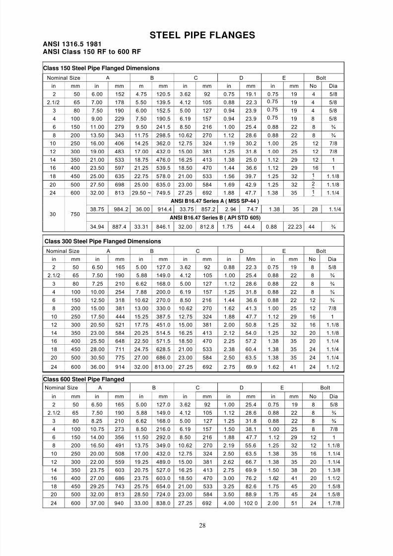
STEEL PIPE FLANGESANSI 1316.5 1981ANSI Class 150 RF to 600 RF
Class 150 Steel Pipe Flanged Dimensions
Nominal Size A B C D E Bolt
in mm in mm m mm in mm in mm in mm No Dia
2 50 6.00 152 4.75 120.5 3.62 92 0.75 19.1 0.75 19 4 5/8
2.1/2 65 7.00 178 5.50 139.5 4.12 105 0.88 22.3 0.75 19 4 5/8
3 80 7.50 190 6.00 152.5 5.00 127 0.94 23.9 0.75 19 4 5/8
4 100 9.00 229 7.50 190.5 6.19 157 0.94 23.9 0.75 19 8 5/8
6 150 11.00 279 9.50 241.5 8.50 216 1.00 25.4 0.88 22 8 ¾
8 200 13.50 343 11.75 298.5 10.62 270 1.12 28.6 0.88 22 8 ¾
10 250 16.00 406 14.25 362.0 12.75 324 1.19 30.2 1.00 25 12 7/8
12 300 19.00 483 17.00 432.0 15.00 381 1.25 31.8 1.00 25 12 7/8
14 350 21.00 533 18.75 476.0 16.25 413 1.38 25.0 1.12 29 12 1
16 400 23.50 597 21.25 539.5 18.50 470 1.44 36.6 1.12 29 16 1
18 450 25.00 635 22.75 578.0 21.00 533 1.56 39.7 1.25 32 1 1.1/8
20 500 27.50 698 25.00 635.0 23.00 584 1.69 42.9 1.25 32 2 1.1/8
24 600 32.00 813 29.50 ~ 749.5 27.25 692
1.88 47.7 1.38 35 1 1.1/4ANSI B16.47 Series A ( MSS SP-44 )
38.75 984.2 36.00 914.4 33.75 857.2 2.94 74.7 1 .38 35 28 1.1/4
ANSI B16.47 Series B ( API STD 605)30 750
34.94 887.4 33.31 846.1 32.00 812.8 1.75 44.4 0.88 22.23 44 ¾
Class 300 Steel Pipe Flanged Dimensions
Nominal Size A B C D E Bolt
in mm in mm in mm in mm in Mm in mm No Dia
2 50 6.50 165 5.00 127.0 3.62 92 0.88 22.3 0.75 19 8 5/8
2.1/2 65 7.50 190 5.88 149.0 4.12 105 1.00 25.4 0.88 22 8 ¾
3 80 7.25 210 6.62 168.0 5.00 127 1.12 28.6 0.88 22 8 ¾
4 100 10.00 254 7.88 200.0 6.19 157 1.25 31.8 0.88 22 8 ¾ 6 150 12.50 318 10.62 270.0 8.50 216 1.44 36.6 0.88 22 12 ¾ 8 200 15.00 381 13.00 330.0 10.62 270 1.62 41.3 1.00 25 12 7/8
10 250 17.50 444 15.25 387.5 12.75 324 1.88 47.7 1.12 29 16 1
12 300 20.50 521 17.75 451.0 15.00 381 2.00 50.8 1.25 32 16 1.1/8
14 350 23.00 584 20.25 514.5 16.25 413 2.12 54.0 1.25 32 20 1.1/8
16 400 25.50 648 22.50 571.5 18.50 470 2.25 57.2 1.38 35 20 1.1/4
18 450 28.00 711 24.75 628.5 21.00 533 2.38 60.4 1.38 35 24 1.1/4
20 500 30.50 775 27.00 686.0 23.00 584 2.50 63.5 1.38 35 24 1.1/4
24 600 36.00 914 32.00 813.00 27.25 692 2.75 69.9 1.62 41 24 1.1/2
Class 600 Steel Pipe Flanged
Nominal Size A B C D E Boltin mm in mm in mm in mm in mm in mm No Dia
2 50 6.50 165 5.00 127.0 3.62 92 1.00 25.4 0.75 19 8 5/8
2.1/2 65 7.50 190 5.88 149.0 4.12 105 1.12 28.6 0.88 22 8 ¾
3 80 8.25 210 6.62 168.0 5.00 127 1.25 31.8 0.88 22 8 ¾
4 100 10.75 273 8.50 216.0 6.19 157 1.50 38.1 1.00 25 8 7/8
6 150 14.00 356 11.50 292.0 8.50 216 1.88 47.7 1.12 29 12 1
8 200 16.50 491 13.75 349.0 10.62 270 2.19 55.6 1.25 32 12 1.1/8
10 250 20.00 508 17.00 432.0 12.75 324 2.50 63.5 1.38 35 16 1.1/4
12 300 22.00 559 19.25 489.0 15.00 381 2.62 66.7 1.38 35 20 1.1/4
14 350 23.75 603 20.75 527.0 16.25 413 2.75 69.9 1.50 38 20 1.3/8
16 400 27.00 686 23.75 603.0 18.50 470 3.00 76.2 1.62 41 20 1.1/2
18 450 29.25 743 25.75 654.0 21.00 533 3.25 82.6 1.75 45 20 1.5/820 500 32.00 813 28.50 724.0 23.00 584 3.50 88.9 1.75 45 24 1.5/8
24 600 37.00 940 33.00 838.0 27.25 692 4.00 102 0 2.00 51 24 1.7/8
8/2/2019 KVC - Stainless Steel Valves
http://slidepdf.com/reader/full/kvc-stainless-steel-valves 31/39
29
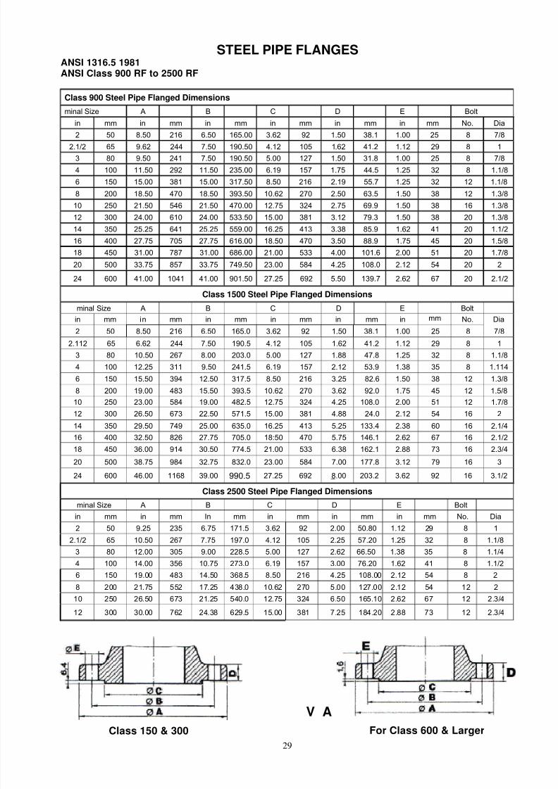
STEEL PIPE FLANGESANSI 1316.5 1981ANSI Class 900 RF to 2500 RF
Class 900 Steel Pipe Flanged Dimensions
minal Size A B C D E Bolt
in mm in mm in mm in mm in mm in mm No. Dia
2 50 8.50 216 6.50 165.00 3.62 92 1.50 38.1 1.00 25 8 7/82.1/2 65 9.62 244 7.50 190.50 4.12 105 1.62 41.2 1.12 29 8 1
3 80 9.50 241 7.50 190.50 5.00 127 1.50 31.8 1.00 25 8 7/8
4 100 11.50 292 11.50 235.00 6.19 157 1.75 44.5 1.25 32 8 1.1/8
6 150 15.00 381 15.00 317.50 8.50 216 2.19 55.7 1.25 32 12 1.1/8
8 200 18.50 470 18.50 393.50 10.62 270 2.50 63.5 1.50 38 12 1.3/8
10 250 21.50 546 21.50 470.00 12.75 324 2.75 69.9 1.50 38 16 1.3/8
12 300 24.00 610 24.00 533.50 15.00 381 3.12 79.3 1.50 38 20 1.3/8
14 350 25.25 641 25.25 559.00 16.25 413 3.38 85.9 1.62 41 20 1.1/2
16 400 27.75 705 27.75 616.00 18.50 470 3.50 88.9 1.75 45 20 1.5/8
18 450 31.00 787 31.00 686.00 21.00 533 4.00 101.6 2.00 51 20 1.7/8
20 500 33.75 857 33.75 749.50 23.00 584 4.25 108.0 2.12 54 20 2
24 600 41.00 1041 41.00 901.50 27.25 692 5.50 139.7 2.62 67 20 2.1/2
Class 1500 Steel Pipe Flanged Dimensions
minal Size A B C D E Bolt
in mm in mm in mm in mm in mm in mm No. Dia
2 50 8.50 216 6.50 165.0 3.62 92 1.50 38.1 1.00 25 8 7/8
2.112 65 6.62 244 7.50 190.5 4.12 105 1.62 41.2 1.12 29 8 1
3 80 10.50 267 8.00 203.0 5.00 127 1.88 47.8 1.25 32 8 1.1/8
4 100 12.25 311 9.50 241.5 6.19 157 2.12 53.9 1.38 35 8 1.114
6 150 15.50 394 12.50 317.5 8.50 216 3.25 82.6 1.50 38 12 1.3/8
8 200 19.00 483 15.50 393.5 10.62 270 3.62 92.0 1.75 45 12 1.5/8
10 250 23.00 584 19.00 482.5 12.75 324 4.25 108.0 2.00 51 12 1.7/8
12 300 26.50 673 22.50 571.5 15.00 381 4.88 24.0 2.12 54 16 214 350 29.50 749 25.00 635.0 16.25 413 5.25 133.4 2.38 60 16 2.1/4
16 400 32.50 826 27.75 705.0 18:50 470 5.75 146.1 2.62 67 16 2.1/2
18 450 36.00 914 30.50 774.5 21.00 533 6.38 162.1 2.88 73 16 2.3/4
20 500 38.75 984 32.75 832.0 23.00 584 7.00 177.8 3.12 79 16 3
24 600 46.00 1168 39.00 990.5 27.25 692 8.00 203.2 3.62 92 16 3.1/2
Class 2500 Steel Pipe Flanged Dimensions
minal Size A B C D E Bolt
in mm in mm In mm in mm in mm in mm No. Dia
2 50 9.25 235 6.75 171.5 3.62 92 2.00 50.80 1.12 29 8 1
2.1/2 65 10.50 267 7.75 197.0 4.12 105 2.25 57.20 1.25 32 8 1.1/8
3 80 12.00 305 9.00 228.5 5.00 127 2.62 66.50 1.38 35 8 1.1/44 100 14.00 356 10.75 273.0 6.19 157 3.00 76.20 1.62 41 8 1.1/2
6 150 19.00 483 14.50 368.5 8.50 216 4.25 108.00 2.12 54 8 2
8 200 21.75 552 17.25 438.0 10.62 270 5.00 127.00 2.12 54 12 2
10 250 26.50 673 21.25 540.0 12.75 324 6.50 165.10 2.62 67 12 2.3/4
12 300 30.00 762 24.38 629.5 15.00 381 7.25 184.20 2.88 73 12 2.3/4
V A L V E W A L L
Class 150 & 300 For Class 600 & Larger
8/2/2019 KVC - Stainless Steel Valves
http://slidepdf.com/reader/full/kvc-stainless-steel-valves 32/39
30
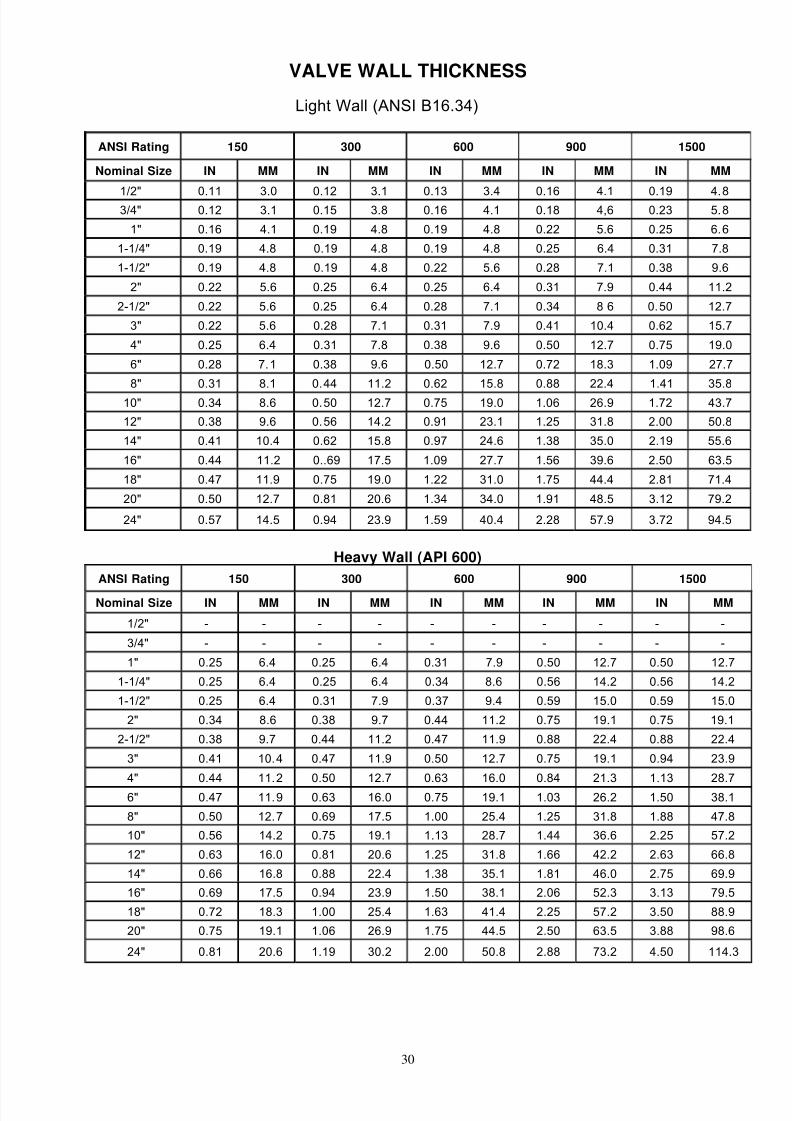
VALVE WALL THICKNESS
Light Wall (ANSI B16.34)
ANSI Rating 150 300 600 900 1500
Nominal Size IN MM IN MM IN MM IN MM IN MM
1/2" 0.11 3.0 0.12 3.1 0.13 3.4 0.16 4.1 0.19 4.83/4" 0.12 3.1 0.15 3.8 0.16 4.1 0.18 4,6 0.23 5.8
1" 0.16 4.1 0.19 4.8 0.19 4.8 0.22 5.6 0.25 6.6
1-1/4" 0.19 4.8 0.19 4.8 0.19 4.8 0.25 6.4 0.31 7.8
1-1/2" 0.19 4.8 0.19 4.8 0.22 5.6 0.28 7.1 0.38 9.6
2" 0.22 5.6 0.25 6.4 0.25 6.4 0.31 7.9 0.44 11.2
2-1/2" 0.22 5.6 0.25 6.4 0.28 7.1 0.34 8 6 0.50 12.7
3" 0.22 5.6 0.28 7.1 0.31 7.9 0.41 10.4 0.62 15.7
4" 0.25 6.4 0.31 7.8 0.38 9.6 0.50 12.7 0.75 19.0
6" 0.28 7.1 0.38 9.6 0.50 12.7 0.72 18.3 1.09 27.7
8" 0.31 8.1 0.44 11.2 0.62 15.8 0.88 22.4 1.41 35.8
10" 0.34 8.6 0.50 12.7 0.75 19.0 1.06 26.9 1.72 43.7
12" 0.38 9.6 0.56 14.2 0.91 23.1 1.25 31.8 2.00 50.8
14" 0.41 10.4 0.62 15.8 0.97 24.6 1.38 35.0 2.19 55.6
16" 0.44 11.2 0..69 17.5 1.09 27.7 1.56 39.6 2.50 63.5
18" 0.47 11.9 0.75 19.0 1.22 31.0 1.75 44.4 2.81 71.4
20" 0.50 12.7 0.81 20.6 1.34 34.0 1.91 48.5 3.12 79.2
24" 0.57 14.5 0.94 23.9 1.59 40.4 2.28 57.9 3.72 94.5
Heavy Wall (API 600)
ANSI Rating 150 300 600 900 1500
Nominal Size IN MM IN MM IN MM IN MM IN MM
1/2" - - - - - - - - - -
3/4" - - - - - - - - - -
1" 0.25 6.4 0.25 6.4 0.31 7.9 0.50 12.7 0.50 12.7
1-1/4" 0.25 6.4 0.25 6.4 0.34 8.6 0.56 14.2 0.56 14.2
1-1/2" 0.25 6.4 0.31 7.9 0.37 9.4 0.59 15.0 0.59 15.0
2" 0.34 8.6 0.38 9.7 0.44 11.2 0.75 19.1 0.75 19.1
2-1/2" 0.38 9.7 0.44 11.2 0.47 11.9 0.88 22.4 0.88 22.4
3" 0.41 10.4 0.47 11.9 0.50 12.7 0.75 19.1 0.94 23.9
4" 0.44 11.2 0.50 12.7 0.63 16.0 0.84 21.3 1.13 28.7
6" 0.47 11.9 0.63 16.0 0.75 19.1 1.03 26.2 1.50 38.1
8" 0.50 12.7 0.69 17.5 1.00 25.4 1.25 31.8 1.88 47.8
10" 0.56 14.2 0.75 19.1 1.13 28.7 1.44 36.6 2.25 57.2
12" 0.63 16.0 0.81 20.6 1.25 31.8 1.66 42.2 2.63 66.8
14" 0.66 16.8 0.88 22.4 1.38 35.1 1.81 46.0 2.75 69.9
16" 0.69 17.5 0.94 23.9 1.50 38.1 2.06 52.3 3.13 79.5
18" 0.72 18.3 1.00 25.4 1.63 41.4 2.25 57.2 3.50 88.9
20" 0.75 19.1 1.06 26.9 1.75 44.5 2.50 63.5 3.88 98.6
24" 0.81 20.6 1.19 30.2 2.00 50.8 2.88 73.2 4.50 114.3
8/2/2019 KVC - Stainless Steel Valves
http://slidepdf.com/reader/full/kvc-stainless-steel-valves 33/39
31
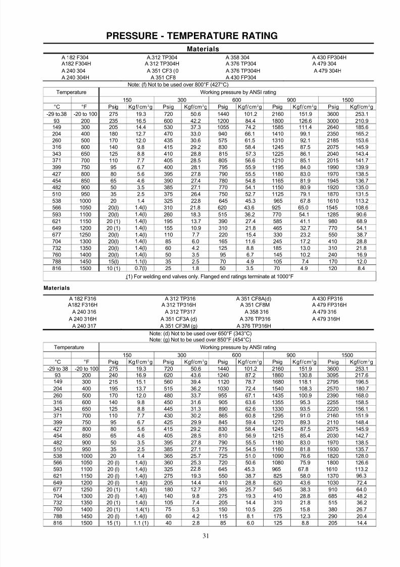
PRESSURE - TEMPERATURE RATING
MaterialsA 182 F304 A.312 TP304 A 358 304 A 430 FP304HA182 F304H A 312 TP304H A 376 TP304 A 479 304
A 240 304 A 351 CF3 (0 A 376 TP304H A 479 304HA 240 304H A 351 CF8 A 430 FP304
Note: (f) Not to be used over 800°F (427°C)
Temperature Working pressure by ANSI rating
150 300 600 900 1500°C °F Psig Kgf/cm 2g Psig Kgf/cm2g Psig Kgf/cm2g Psig Kgf/cm2g Psig Kgf/cm2g
-29 to-38 -20 to 100 275 19.3 720 50.6 1440 101.2 2160 151.9 3600 253.1
93 200 235 16.5 600 42.2 1200 84.4 1800 126.6 3000 210.9149 300 205 14.4 530 37.3 1055 74.2 1585 111.4 2640 185.6204 400 180 12.7 470 33.0 940 66.1 1410 99.1 2350 165.2260 500 170 12.0 435 30.6 575 61.5 1310 92.1 2185 153.6316 600 140 9.8 415 29.2 830 58.4 1245 87.5 2075 145.9343 650 125 8.8 410 28.8 815 57.3 1225 86.1 2040 143.4371 700 110 7.7 405 28.5 805 56.6 1210 85.1 2015 141.7
399 750 95 6.7 400 28.1 795 55.9 1195 84.0 1990 139.9
427 800 80 5.6 395 27.8 790 55.5 1180 83.0 1970 138.5454 850 65 4.6 390 27.4 780 54.8 1165 81.9 1945 136.7482 900 50 3.5 385 27.1 770 54.1 1150 80.9 1920 135.0510 950 35 2.5 375 26.4 750 52.7 1125 79.1 1870 131.5
538 1000 20 1.4 325 22.8 645 45.3 965 67.8 1610 113.2566 1050 20(l) 1.4(l) 310 21.8 620 43.6 925 65.0 1545 108.6
593 1100 20(l) 1.4(l) 260 18.3 515 36.2 770 54.1 1285 90.6
621 1150 20 (1) 1.4(l) 195 13.7 390 27.4 585 41.1 980 68.9
649 1200 20 (1) 1.4(l) 155 10.9 310 21.8 465 32.7 770 54.1677 1250 20(l) 1.4(l) 110 7.7 220 15.4 330 23.2 550 38.7704 1300 20(l) 1.4(l) 85 6.0 165 11.6 245 17.2 410 28.8732 1350 20(l) 1.4(l) 60 4.2 125 8.8 185 13.0 310 21.8760 1400 20(l) 1.4(l) 50 3.5 95 6.7 145 10.2 240 16.9
788 1450 15(l) 1.1(l) 35 2.5 70 4.9 105 7.4 170 12.0
816 1500 10 (1) 0.7(l) 25 1.8 50 3.5 70 4.9 120 8.4
(1) For welding end valves only. Flanged end ratings terminate at 1000°F
Materials
A 182 F316 A 312 TP316 A 351 CF8A(d) A 430 FP316A182 F316H A 312 TP316H A 351 CF8M A 479 FP316H
A 240 316 A 312 TP317 A 358 316 A 479 316
A 240 316H A 351 CF3A (d) A 376 TP316 A 479 316H
A 240 317 A 351 CF3M (g) A 376 TP316H
Note: (d) Not to be used over 650°F (343°C)Note: (g) Not to be used over 850°F (454°C)
Temperature Working pressure by ANSI rating
150 300 600 900 1500°C °F Psig Kg f/cm 2g Psig Kgf/cm2g Psig Kgf/cm2g Psig Kgf/cm2g Psig Kgf/cm2g
-29 to 38 -20 to 100 275 19.3 720 50.6 1440 101.2 2160 151.9 3600 253.193 200 240 16.9 620 43.6 1240 87.2 1860 130.8 3095 217.6149 300 215 15.1 560 39.4 1120 78.7 1680 118.1 2795 196.5
204 400 195 13.7 515 36.2 1030 72.4 1540 108.3 2570 180.7
260 500 170 12.0 480 33.7 955 67.1 1435 100.9 2390 168.0316 600 140 9.8 450 31.6 905 63.6 1355 95.3 2255 158.5343 650 125 8.8 445 31.3 890 62.6 1330 93.5 2220 156.1371 700 110 7.7 430 30.2 865 60.8 1295 91.0 2160 151.9399 750 95 6.7 425 29.9 845 59.4 1270 89.3 2110 148.4427 800 80 5.6 415 29.2 830 58.4 1245 87.5 2075 145.9454 850 65 4.6 405 28.5 810 56.9 1215 85.4 2030 142.7
482 900 50 3.5 395 27.8 790 55.5 1180 83.0 1970 138.5510 950 35 2.5 385 27.1 775 54.5 1160 81.8 1930 135.7538 1000 20 1.4 365 25.7 725 51.0 1090 76.6 1820 128.0566 1050 20 (l) 1.4(l) 360 25.3 720 50.6 1080 75.9 1800 126.6593 1100 20 (l) 1.4(l) 325 22.8 645 45.3 965 67.8 1610 113.2621 1150 20 (l) 1.4(l) 275 19.3 550 38.7 825 58.0 1370 96.3
649 1200 20 (l) 1.4(t) 205 14.4 410 28.8 620 43.6 1030 72.4
677 1250 20 (1) 1.4(l) 180 12.7 365 25.7 545 38.3 910 64.0
704 1300 20 (l) 1.4(l) 140 9.8 275 19.3 410 28.8 685 48.2732 1350 20 (1) 1.4(l) 105 7.4 205 14.4 310 21.8 515 36.2760 1400 20 (1) 1.4(1) 75 5.3 150 10.5 225 15.8 380 26.7
788 1450 20 (l) 1.4(l) 60 4.2 115 8.1 175 12.3 290 20.4816 1500 15 (1) 1.1 (1) 40 2.8 85 6.0 125 8.8 205 14.4

8/2/2019 KVC - Stainless Steel Valves
http://slidepdf.com/reader/full/kvc-stainless-steel-valves 34/39
32
OPTIONAL MATERIALS
VALVE SHELL MATERIALS
Standard Shell materials are ASTM Grade CF8M. Other material are available upon request.
ASTM Designation Maximum Working Temperature
A351 Gr. CF8M 1000°F (538°C)
A351 Gr. CF8 1000°F (538°C)
A351 Gr.CF3M 850°F (454°C)
A351 Gr.CF3M 800°F (427°C)
A351 Gr.CN7M 300°F (140°C)
OPTIONAL GLAND PACKING MATERIALS
Depending on the service conditions, various materials are available optionally for gland packings
Packing Material Service Condition
Inconel wire asbestos 1200°F (640°C) Hear resistant
Virgin PTFE 370°F (188°C) Corrosion resistant
Graphite asbestos 640°F (343°C)
Flexible graphite (grafoil*`) 1500°F (816°C) Heat and corrosion resistant
OPTIONAL FLANGE GASKET MATERIALS
Depending on the service conditions, various materials are available optionally for gland packings
Gasket materials
Spiral wound metal graphite filledRing Joint metal
Corrugated metal
Flexible graphite (grafoil")
Virgin PTFE
Glass filled PTFE
* Grafoil is a registered trademark of Union Carbide Corp.

8/2/2019 KVC - Stainless Steel Valves
http://slidepdf.com/reader/full/kvc-stainless-steel-valves 35/39
33
PACKING MATERIAL & CONSTRUCTION
MakersConstruction & Features Performance Main Applications
ChesertonJohnCrane
Pillar Palmetto
Round Braided AsbestosImpregnated with High Temp.
Lubricant & Graphila
TEMP : 660: 660 °F (350°)
PRESS: 570 PSI (40kgf/cmZ)
Water, saturated steam
general purpose valves
510
310815 114 -
Braided Asbestos
Asbestos with Inconel Wire
Braided around a
Resilent Asbestos Core
TEMP: 1200° F (650°)
PRESS: 6000 PSI (425kgf/cmZ)
Saturated stem, hot oils,
petroleum-base
hydrocarbons, solvents, gas,
ammonia, valves, cocks
1000
1500
C-1068
1871316 4062
Braided Asbestos, TFE
Lubrication
Interlaced Braided Asbestos
with TFE Suspension
TEMP: -330° F - 500° F
(-200° C - 260° C)
PRESS: 2840 PSI (200kgf/cmZ
)
PH : 2 - 3
Solvents, acids, alkalis,
oxygen and LNG.
322
1722
C064513
4533 1347H
Interlaced Braided
Specially Lubricated TFE
Multiflament Yarn with
TFE Dispersion
TEMP: -150° F - 500° F
(-100° C - 260° C)
PRESS: 1420 PSI (100kgf/cm2)
PH : 0 - 14
Solvents, strong acids,
strong alkalis, fluids which
does not allow pollution.
1728
328C1050 4505L 1367S
Interlaced Braided
TFE Multifilament Yarn
with TFE Suspension
TEMP: -330° F - 500° F
(-200° C - 260° C)
PRESS: 2840 PSI (200kgflcmZ)
PH:0-14
Solvents strong acids,
strong alkalis, and fluids
which does not allow
pollution.
324
1724C1045 4525 1367H
Graphoil
Graphoil flexible Graphite
Containing No Binders,
Lubricants or Other Additives
TEMP: -1200'F (650'C)
PRESS: 6000 PSI (425kgf/cm2)
PH : 0 - 14
Water, steam oils, oil gases,
solvents, heat transer oil,
LNG strong acids and
strong alkalis.
GTP 229C 6610 -
Non-Asbestos Wire
Inserted core of Chopped
Glass Fiber with Jacket of
Wire Inserted Glass Yarn
Graphited Outside
TEMP: -1200'F (650'C)
PRESS: 6000 PSI (425kgf/cm2)
PH : 2 -12
For air, water, steam, oil
liquid petroleum, chemical,
corosive and similar
services
1200 2871 6711 -
TFE Impregnated syntex
asbestos-free yarn
with high temperature break-
in lube. Inter woven TM braid,
Non-Contaminating
TEMP: 450° F (232° C)
PRESS: 1500 PSI
(105.5kgf/cm2)
Mild acids, Caustics,
Solvents, Steam, Oils,
neutral fluids.
- - - 1347AF
Lattice-braiding carbon fibers
packing and impregnating the
fibers with the special
Lubricant
TEMP: -420° F - 1400° F
(-250° C - 800° C)
PRESS: 1420 PSI (100kgf/cmZ)
PH : 0 - 14
Water, Hot water, oils
Solvents, strong acids and
strong alkalis.
- 1625G 6527 -

8/2/2019 KVC - Stainless Steel Valves
http://slidepdf.com/reader/full/kvc-stainless-steel-valves 36/39
34
GASKET SPECIFICATION & CONSTRUCTION
Performance Construction & Features Main Application
Compressed asbestos joint sheet made by Water, sea water, hot water, high-pressure
using selected chyrsotile asbestos as main steam, air, acids, alkalism aqueous salt
Temp: 660°F (350°C) material, adding a small amount of a synthetic solutions, animal and vegetable oils,
Pressure: 500 PSI (35kfglcmZ) rubber binder for its high resilience, sealability aicohols, fuel oils, hydraulic fluids,
and good chemical resistance, it can be used lubricatiing oil, aliphatic solvents and their
for a wide range of fluids and apparatus. vapors, various gases and liquefied gasses.Temp: -150°F - 300°F An enveloped type gasket made by lining a
(100°C - 150°C) 1mm thick teflon disk and inserting a core Strong acids, strong alkalis, oxygen,
Press: 285PSI (20kgf/cm 2 ) Inside chlorine gas, and organic solvents.
A spiral wound gasket made by alternately
winding the metal hoops formed to a V shape
Temp: 1,100°F (600°C) and the asbestos sheets subjected to Water, steam, oils, oil gas, gases and
Press: 6,000 PSI (425 kg f/cmZ) impermeability treatment. Featuring excellent solvents.
gas sealability, heat resistance and elasticity,this Standard Materials.
Hoop ................. SUS304
Filler .................. Asbestos sheet
Inner ring ............... SPCC
Outer ring .............. SPCC
This is an entirely new type of spiral wound
gasket using teflon soft tapes of 100% PTFE
Temp: 1 ,100°F (600°C) having resilence and elasticity for the filler General chemicals, corrosive fluids, gases
Press: 6,000 PSI (425 kgf/cm ) material it has superior gas sealability and dangerous fluids,
resistance and other property advantages and is usable for virtually any kind
of fluids. Standard Materials
Hoop ................. SUS304
Filler ............... Soft teflon
Inner ring ........... SUS304
Outer ring ........... SUS304
A spiral wound gasket using grafoil tapes for
filler material, and featuring excellent gasTemp: 1,600°F (870°C) sealability, heat resistance and chemical Steam of high temperatures and high
Press: 6,000 PSI (425 kg f/cm2) resistance. This provides the highest level of pressures, dangerous gases. He gas,performances among all the existing gaskets. ammonia and LNG. .Standard Materials
Hoop ................. SUS304
Filler ............ raphoil tapes
Inner ring ............... SPCC
Outer ring .............. SPCC
Flat-shaped metallic gasket which an asbestos Steam of high temperatures and high
Depends on metal materials. mill board is jacketed with a single ply of metal pressures, gases, oil gas, solvent vapors,
sheet. pipe flange, solvent vapors, and covers of
pressure vessels.
Pipe flanges and heat exchangers of
Depends on metal materials. Flat-shaped metallic gasket which an asbestos petroleum refining industry and
mill board with a metal sheet in double petrochemical industry.
Metallic gasket made by fabricating a metal
waveforms to enable more contact face Bonnets of various valves for steam of
Depends on metal materials. pressure to be taken, and adding the spring high temperatures and low pressures, oil,
effect to improve sealability. gas, solvent vapors and heat medium oil.
Metallic gasket made by machining Pipe flanges and valve bonnets for steam
Depends on metal materials. concentrically sharp V-grooves of 60° or 90° to of high temperatures and high pressures,
a flat metal gasket at roughly 1 mm pitch. and gases.
High-temperature high--pressure pipe
Depends on metal materials. Metallic ring joint by machining various metal flanges, valve bonnets and heat
materials to an octagonal shape. exchangers.
Metallic ring joint gasket made by machining High-temperature high pressure pipe
Depends on metal materials. metal materials into an oval section. flanges, , valve bonnets and heat exchanges.

8/2/2019 KVC - Stainless Steel Valves
http://slidepdf.com/reader/full/kvc-stainless-steel-valves 37/39
35
GASKET SPECIFICATION & CONSTRUCTION
Makers Cross Section
Name Crane Jeil Pillar Tombo Valque
Universal Asbestos Joint
Sheet
890
891
5700S 5000 1100 1500
Lip Type Enveloped Gasket 11-C - 4430 9010A 7030
911 1804 2200 1804 590
- 3804-TF 2300 9090 7590 Spiral Wound Gasket
- 3804-SF 2600 1804GR 6590V
Single Metal Jacketed Gasket 923 1840 1000 1840 580
Double Metal JacketedGasket
- 1841 1004 1840 580
Corrugated Gasket Soft Iron 900 1870 1200 1880 500
Serrated Gasket Metal 941 - 1300 1850-S 540
Octagonal Ring Joint Gasket 954 - 1500 1850-L 550SZ
Oval Ring Joint Gasket - - 1501 1850V 5500Z

8/2/2019 KVC - Stainless Steel Valves
http://slidepdf.com/reader/full/kvc-stainless-steel-valves 38/39
36
TERMS & CONDITIONS OF SALE
Quotation & OffersAll goods quoted are FOB our warehouse, with inland freight to destination for account of the buyer, either on collect basisor prepaid and billed for payment by the Buyers only. Unless otherwise stated, all quoted price are valid for 30 days only.Published price are subject to changes without prior notice.
DeliveryDeliveries quoted are estimated basing on availability of Seller's stock and/or production schedule at time of quotation, aresubject to changes in the event of prior sales, rescheduling or any occurrence beyond the Seller's control, though theSeller, as a gesture of goodwill, will do its best to stay as close as possible to the deliveries estimated. Delivery of materials to a common carrier shall be considered as delivery to the Buyer, and shall be at the Buyer's risk thereafter.Claims for losses or damages to the materials in transit shall be filed by the Buyer direct with the carrier. All claims for shortages, corrections or deductions must be made to the Seller within ten (10) days after receipt of goods.
Cancellations & ReturnsAll cancellations, changes and returns, etc... cannot be made without Seller's formal prior consents or acceptances. Acancellation and re-installation charge will apply unless otherwise waived by the Seller. Special items are not subject tocancellation or returns.
Force MajeureSeller is not to be held responsible for any delays in delivery of defaults in completing an order or contract due to forcemajeure such as strikes, work stoppages, fires, floods, accidents, inability to obtain fuel and transportation means,vendors' delayed deliveries of materials, parts, components, goods, etc... to the Sellers, acts of God, and/or any other causes beyond Seller's control.
TaxesSeller's prices are exclusive of all taxes, which, if applicable under governmental laws, shall be wholly for the Buyer'saccount and to be fully paid for by the Buyer. Where the Buyer is lawfully entitled to exemption from any tax, all necessarydocumentation must be provided by the Buyer to the Seller to effect such exemption. Any taxes, Interests and penaltiesassessed against the Seller on transactions which are otherwise determined as taxable, shall be borne by the Buyer. Theterm "Taxes used here shall include any impost, duty levy or other charges imposed by any government or agency thereof upon the property, services or parties hereto, but shall not include those measured by the net income of the Seller.
ErrorsAll clerical and computational errors and/or omissions are exempted and are to be corrected by the Seller.
WarrantyAll KVC products are guaranteed to the original Buyer only for a one year period from and after the invoice date againstdefects in material and workmanship under normal and proper use and service, and not caused or resulting from improper usage or application, improper installation, improper maintenance and repairs, modifications or alterations, normal wear and tears, corrosion, erosion or chemical attacks. Seller's obligation under this warranty is limited only to repairing or replacing, at Seller's election, any parts or products determined by the Seller to be defective, or refunding the purchasingprice to the original Buyer. Seller shall bear normal surface transportation cost for shipping the replacements, but shall in
no event hear any losses or damages, installation, re-installation, engineering, or any other costs incurred thereof by theBuyer.
LiabilityNotwithstanding any provision in the Buyer's order or elsewhere to the contrary, under no circumstances shall Seller beliable, in contract, tort or otherwise, for any incidental, special or consequential damages, whatsoever (Including but notlimited to loss of revenue, loss of production or loss of use of any products, or other items) whether or not arising fromSeller's negligence and delays, actual or imputed.
PartiesThe terms "Seller" refers to KVC Co., LTD and the term "Buyer" refers to the Person, Party of Company purchasing goodsand / or services from KVC Co., LTD.

8/2/2019 KVC - Stainless Steel Valves
http://slidepdf.com/reader/full/kvc-stainless-steel-valves 39/39
PRODUCTION RANGE
Our production range which includes cast and forged valves of carbon and stainless steel and also cast iron, to API600, API 603, API 6D, BS & MSS. ANSI 150 to 1500 is fully detailed in the following catalogues :-
Catalogue FSV-2003-R2 - Forged Steel Valves to API 602-BS5352, ANSI 150 to 1500, Gate Globeand Swing Check Valves
Catalogue CSV-2003 - Cast Steel Valves to API 600 & API 603, ANSI 150 to 1500, Gate, Globe andSwing Check Valves
Catalogue FSBV-03/98 - Forged Steel & Stainless Steel Ball Valves to BS5351 2-piece & 3-piece body,
ANSI 800 & 1500
Catalogue BV - Cast Steel Ball Valves to API 6D, ANSI 150 to 1500
Catalogue CIV-2004 - Cast Iron Valves to MSS SP-70, 71 & 85, ANSI 125
Leaflet - Ductile Iron Gate Valves (Clamp type), ANSI B2,1
Drawing - Cast Steel Strainer, ANSI 150
The information presented in this catalogue is correct at time of printing. KVC reserves the right to change designs dimensions and l or material specifications without notice.


