

TECHNICALPROCEDURETRAILER SUSPENSION SYSTEMS
SUBJECT: RF Model Service ManualLIT NO: L1029DATE: January 2009
TABLE OF CONTENTS
General Information . . . . . . . . . . . . . . . . . . . . . . . . . . . . . . . . . . . . . . . . . . . . . . . . . . . . . . . . . . . . . . .2
Model Identification . . . . . . . . . . . . . . . . . . . . . . . . . . . . . . . . . . . . . . . . . . . . . . . . . . . . . . . . . . . . . . .3
Proper Suspension Operation . . . . . . . . . . . . . . . . . . . . . . . . . . . . . . . . . . . . . . . . . . . . . . . . . . . . . . . .6
Inspection Procedure . . . . . . . . . . . . . . . . . . . . . . . . . . . . . . . . . . . . . . . . . . . . . . . . . . . . . . . . . . . . . .7
Trailer Suspension Inspection Intervals and Suggestions . . . . . . . . . . . . . . . . . . . . . . . . . . . . . . . . . . . . .9
Suspension Maintenance . . . . . . . . . . . . . . . . . . . . . . . . . . . . . . . . . . . . . . . . . . . . . . . . . . . . . . . . . . .10
Pressure Protection Valve . . . . . . . . . . . . . . . . . . . . . . . . . . . . . . . . . . . . . . . . . . . . . . . . . . . . . . . . . . .11
Dump Valve (If Equipped) . . . . . . . . . . . . . . . . . . . . . . . . . . . . . . . . . . . . . . . . . . . . . . . . . . . . . . . . . .12
Height Control Valve . . . . . . . . . . . . . . . . . . . . . . . . . . . . . . . . . . . . . . . . . . . . . . . . . . . . . . . . . . . . . .12
Height Control Valve Replacement Procedure . . . . . . . . . . . . . . . . . . . . . . . . . . . . . . . . . . . . . . . . . . . . .13
Ride Height Adjustment . . . . . . . . . . . . . . . . . . . . . . . . . . . . . . . . . . . . . . . . . . . . . . . . . . . . . . . . . . . .14
Air Spring Replacement . . . . . . . . . . . . . . . . . . . . . . . . . . . . . . . . . . . . . . . . . . . . . . . . . . . . . . . . . . . .15
Air Spring Installation . . . . . . . . . . . . . . . . . . . . . . . . . . . . . . . . . . . . . . . . . . . . . . . . . . . . . . . . . . . . .17
Shock Absorber Replacement . . . . . . . . . . . . . . . . . . . . . . . . . . . . . . . . . . . . . . . . . . . . . . . . . . . . . . . .18
Pivot Connection . . . . . . . . . . . . . . . . . . . . . . . . . . . . . . . . . . . . . . . . . . . . . . . . . . . . . . . . . . . . . . . . .19
Pivot Bushing . . . . . . . . . . . . . . . . . . . . . . . . . . . . . . . . . . . . . . . . . . . . . . . . . . . . . . . . . . . . . . . . . . .20
Bushing Installation . . . . . . . . . . . . . . . . . . . . . . . . . . . . . . . . . . . . . . . . . . . . . . . . . . . . . . . . . . . . . .22
Suspension Axle Alignment . . . . . . . . . . . . . . . . . . . . . . . . . . . . . . . . . . . . . . . . . . . . . . . . . . . . . . . . .25
Torque Specifications . . . . . . . . . . . . . . . . . . . . . . . . . . . . . . . . . . . . . . . . . . . . . . . . . . . . . . . . . . . . . .29
Appendix . . . . . . . . . . . . . . . . . . . . . . . . . . . . . . . . . . . . . . . . . . . . . . . . . . . . . . . . . . . . . . . . . . . . . .30
RF MODEL SERVICE MANUAL
2L1029
GENERAL INFORMATION
The description and specifications contained in thisservice publication are current at the time of printing.
Hendrickson reserves the right to discontinue or modify its models and/or procedures and to change specifications at any time without notice.
IMPORTANT NOTICE
Any reference to brand names in this publication are made as an example of the types of tools andmaterials recommended for use and should not be considered an endorsement. Equivalents may be used.
This symbol is used throughout this manual to call attention to procedures wherecarelessness or failure to follow specificinstructions may result in personal injury and / or component damage.
Departure from the instructions, choice of tools, materials and recommended parts mentioned in this publication may jeopardize the personal safety of the service technician and vehicle operator.
WARNING: FAILURE TO FOLLOW INDICATEDPROCEDURES CREATES A HIGH RISK OF PERSONAL INJURY TO THE SERVICING TECHNICIAN.
CAUTION: Failure to follow indicatedprocedures may cause componentdamage or malfunction.
IMPORTANT: Highly recommended procedures for proper service of this unit.
NOTE: Additional service information not covered inthe service procedures.
TIP: Helpful removal and installation procedures toaid in the service of this unit.
ALWAYS USE GENUINE HENDRICKSONPARTS
Hendrickson recommends following all manufacturers’ recommendations for the proper handling and disposal of lubricants and solvents. For further information contact the supplier of lubricants and solvents.
CAUTION: Welding or machining on any axlecomponent is prohibited unlessnoted otherwise in this document.
INTRODUCTIONHendrickson presents this publication to aid in maintenance and overhaul of Hendrickson TrailerSuspension Systems.
For any questions call Hendrickson Technical ServiceDepartment at 800-455-0043 in the United States or800-668-5360 in Canada.
Instructions contained cover the models listed below.

RF MODEL SERVICE MANUAL
3L1029
MODEL LISTING
This publication covers all RF models.
MODEL IDENTIFICATION
NOTE: Models shipped before January 5,2007, will be equipped with a Dana Spiceridentification tag and models shipped afterJanuary 5, 2007, will be equipped with aHendrickson identification tag. All modelslisted are now serviced under HendricksonTrailer Suspension Systems, regardless ofmanufacturer addressed on the identificationtag. All other tag identification information has remains the same.
02-11060-59
SERIAL#:
RF20PW6HX167DAXXAA 1
PART#:
DECRIPTION:
8/01/03
264525
WIP#:
RIDE
&CO
NTRO
LSY
STEM
SM
ONTG
OMER
Y,AL
ABAM
A
287UX045
02-11060-59SERIAL#:
RF20PW6HX167DAXXAA 1PART#:
DECRIPTION:
8/01/03
264525WIP#:
02A-123456SERIAL#:
D22AX603A562-1079
D22-FC167W-NH 77.5
PART#:
DECRIPTION:
11/19/02
264525WIP#:
02A-123456SERIAL#:
D22AX603A562-1079
D22-FC167W-NH 77.5
PART#:
DECRIPTION:
11/19/02
264525WIP#:
RID
E &
CON
TRO
L SY
STEM
S
MO
NTG
OM
ERY,
ALA
BAM
A
1
2
3
1 - Side of suspension arm2 - Hendrickson suspension assembly identification tag3 - Hendrickson axle identification tag
RF MODEL SERVICE MANUAL
4L1029
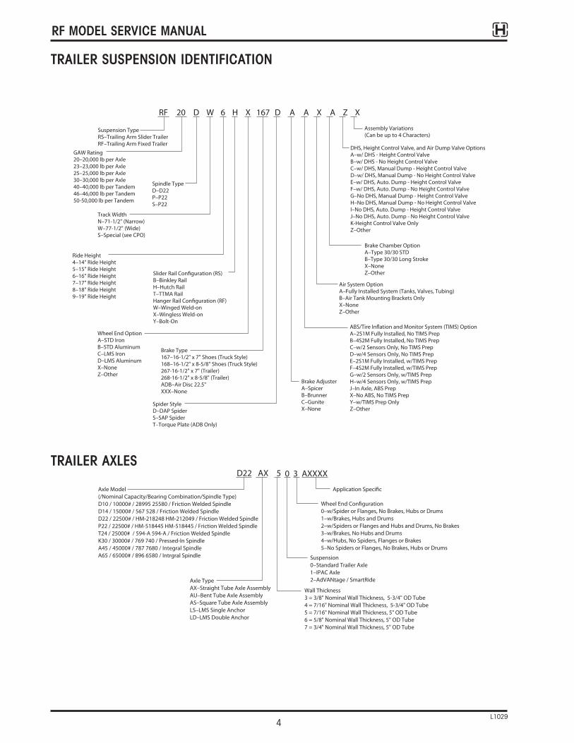
RF 20 D W 6 H X 167 D A A X A Z X
Suspension TypeRS–Trailing Arm Slider TrailerRF–Trailing Arm Fixed Trailer
Assembly Variations(Can be up to 4 Characters)
GAW Rating20–20,000 lb per Axle23–23,000 lb per Axle 25–25,000 lb per Axle30–30,000 lb per Axle 40–40,000 lb per Tandem 46–46,000 lb per Tandem50-50,000 lb per Tandem
DHS, Height Control Valve, and Air Dump Valve OptionsA–w/ DHS - Height Control ValveB–w/ DHS - No Height Control ValveC–w/ DHS, Manual Dump - Height Control ValveD–w/ DHS, Manual Dump - No Height Control ValveE–w/ DHS, Auto. Dump - Height Control Valve F–w/ DHS, Auto. Dump - No Height Control Valve G–No DHS, Manual Dump - Height Control ValveH–No DHS, Manual Dump - No Height Control Valve I–No DHS, Auto. Dump - Height Control ValveJ–No DHS, Auto. Dump - No Height Control Valve K-Height Control Valve Only Z–Other
Track WidthN–71-1/2" (Narrow)W–77-1/2" (Wide)S–Special (see CPO)
Spindle TypeD–D22P–P22S–P22
Ride Height4–14" Ride Height5–15" Ride Height6–16" Ride Height7–17" Ride Height8–18" Ride Height9–19" Ride Height
Brake Chamber OptionA–Type 30/30 STDB–Type 30/30 Long StrokeX–NoneZ–Other
Air System OptionA–Fully Installed System (Tanks, Valves, Tubing)B–Air Tank Mounting Brackets Only X–NoneZ–Other
Brake AdjusterA–SpicerB–BrunnerC–GuniteX–None
Wheel End OptionA–STD IronB–STD AluminumC–LMS IronD–LMS AluminumX–NoneZ–Other
Slider Rail Configuration (RS)B–Binkley RailH–Hutch Rail T–TTMA RailHanger Rail Configuration (RF) W–Winged Weld-onX–Wingless Weld-on Y–Bolt-On
Brake Type167–16-1/2" x 7" Shoes (Truck Style)168–16-1/2" x 8-5/8" Shoes (Truck Style) 267-16-1/2" x 7" (Trailer) 268-16-1/2" x 8-5/8" (Trailer) ADB–Air Disc 22.5"XXX–None
ABS/Tire Inflation and Monitor System (TIMS) OptionA–2S1M Fully Installed, No TIMS PrepB–4S2M Fully Installed, No TIMS PrepC–w/2 Sensors Only, No TIMS PrepD–w/4 Sensors Only, No TIMS PrepE–2S1M Fully Installed, w/TIMS PrepF–4S2M Fully Installed, w/TIMS PrepG–w/2 Sensors Only, w/TIMS PrepH–w/4 Sensors Only, w/TIMS PrepJ–In Axle, ABS PrepX–No ABS, No TIMS PrepY–w/TIMS Prep Only Z–Other
Spider StyleD–DAP SpiderS–SAP Spider T–Torque Plate (ADB Only)
D22 AX 5 0 3 AXXXX
Axle Model(/Nominal Capacity/Bearing Combination/Spindle Type)D10 / 10000# / 28995 25580 / Friction Welded SpindleD14 / 15000# / 567 528 / Friction Welded SpindleD22 / 22500# / HM-218248 HM-212049 / Friction Welded SpindleP22 / 22500# / HM-518445 HM-518445 / Friction Welded SpindleT24 / 25000# / 594-A 594-A / Friction Welded SpindleK30 / 30000# / 769 740 / Pressed-In SpindleA45 / 45000# / 787 7680 / Integral SpindleA65 / 65000# / 896 6580 / Intrgral Spindle
Application Specific
Wheel End Configuration0–w/Spider or Flanges, No Brakes, Hubs or Drums1–w/Brakes, Hubs and Drums2–w/Spiders or Flanges and Hubs and Drums, No Brakes3–w/Brakes, No Hubs and Drums4–w/Hubs, No Spiders, Flanges or Brakes5–No Spiders or Flanges, No Brakes, Hubs or Drums
Axle TypeAX–Straight Tube Axle AssemblyAU–Bent Tube Axle AssemblyAS–Square Tube Axle AssemblyLS–LMS Single AnchorLD–LMS Double Anchor
Wall Thickness3 = 3/8" Nominal Wall Thickness, 5-3/4" OD Tube 4 = 7/16" Nominal Wall Thickness, 5-3/4" OD Tube 5 = 7/16" Nominal Wall Thickness, 5" OD Tube6 = 5/8" Nominal Wall Thickness, 5" OD Tube7 = 3/4" Nominal Wall Thickness, 5" OD Tube
Suspension0–Standard Trailer Axle1–IPAC Axle2–AdVANtage / SmartRide
TRAILER SUSPENSION IDENTIFICATION
TRAILER AXLES

287UX041
2
212221
22
22
2623
25
25
24
3
18
19
19204
4
17
16
5
67
15
1
28
28
2730
2730
4 2221
FRONT
AdVANtagePivot Connection
11 14 13
1314
12
89
10
98
RF MODEL SERVICE MANUAL
5L1029
1 - Bracket, ride height valve2 - Ride height valve assembly3 - Shock absorber assembly4 - Washer, flat5 - Air spring, suspension6 - Flanged lock nut7 - Cap8 - Washer, cam alignment9 - Wear washer10 - Bushing, pivot
11 - Lock nut, pivot12 - Bolt, pivot bolt13 - Washer flat, pivot bolt14 - Hardened washer15 - Brake assembly16 - Frame bracket assembly17 - Valve, air dump (optional)18 - Bolt, shock, upper19 - Nut, shock20 - Bolt, shock, lower
21 - Nut, ride height valve22 - Washer, ride height valve23 - Bolt, ride height valve24 - Linkage, ride height valve25 - Bolt, ride height pivot26 - Valve, ride height control27 - Flanged lock nut, air bag28 - Top plate29 - Lateral gusset30 - Plug, pipe
PART IDENTIFICATION

RF MODEL SERVICE MANUAL
6L1029
PROPER SUSPENSION OPERATION
Hendrickson air suspension models covered in thismanual are controlled by a single height controlvalve. Use of more than one valve may be requiredfor some widespread applications.
When properly adjusted, the height control valve will support the load being carried and maintain aconstant ride height by controlling the air pressure in the air springs.
It is recommended that a Pressure Protection Valve(PPV) be used between the air supply and the height control valve. The trailer air pressure must be maintained in excess of 75 psig (5.2 bar). The opening pressure of the PPV is typically 75 psig (5.2 bar) and is required to open the air pressure protection valve, which maintains safe air brake pressure in the event of air loss in the suspension system.
NOTE: If equipped with a DHS system, the kickstandassembly will need to be manuallydisengaged before the suspension can belowered onto the air spring internal bumpers.
CAUTION: Be sure tires are not rubbing theunderside of the trailer or any othercomponents.

RF MODEL SERVICE MANUAL
7L1029
INSPECTION
WARNING: TO PREVENT SERIOUS EYE INJURY,ALWAYS WEAR EYE PROTECTIONWHEN PERFORMING VEHICLEMAINTENANCE OR SERVICE.
WARNING: A SCHEDULE FOR PHYSICAL ANDVISUAL INSPECTIONS SHOULD BEESTABLISHED BY THE OPERATORBASED ON SEVERITY OF OPERATION.
During each pre-trip and safety inspection of the vehicle, perform a visual inspection of the suspension.
Listen for air leaks and visually check for:
• Bolt movement – loose dirt, rust or metal wear around bolt head and nut
• Air springs – wear damage and proper inflation
• Shock absorbers – leaking or damaged• Cracked parts or welds
CAUTION: Always block wheels to preventrollaway when working under thevehicle.
INSPECTION PROCEDURE
Prior to placing unit in service, check the followingitems:
1. Build air pressure above 75 psig (5.2 bar). Withthe vehicle shut off, check for air leaks.
2. With vehicle on level surface and air supplypressure in excess of 75 psig (5.2 bar), checkair springs for equal firmness.
3. Check shock absorbers for proper installation.Torque bolts to 210-235 ft. lbs. (285-319 N•m).
4. Check for 13/4 in. (44 mm) minimum clearancearound air springs with vehicle loaded.
5. Ride height should be within 1/8 in. (3 mm) ofrecommended height measured from bottom offrame to centerline of axle. Refer to your specificmodel for proper ride height measurement.
6. Verify torque on pivot nuts to 700-800 ft. lbs.(950-1085 N•m) on AdVANtage 11/8 in bolt.
Refer to the table for inspection intervals.

RF MODEL SERVICE MANUAL
8L1029
When (Frequency) What (Activity)Initial Inspection • Check and re-torque all bolts and nuts at the suspension and axle connections After first 5,000 miles (See Note 1)
(8,047 km) • Check and re-torque all other suspension related hardware (See Note 1)Every 25,000 to 30,000 • Check brake lining wear and estimate required replacement datemiles (43,233 to 48,279 Km) - Replace brake shoes and lining assembly when lining thickness is 1/4 in (6 mm)
or less at thinnest point• Check brake shoes and lining assembly for damage
- Replace immediately if lining is cracked, broken or oil soaked• Check brake camshaft, spider bushing and support brake bushing for damage
or wear- Replace or repair if any signs of damage or wear are discovered
Annually (from in–service date) • Inspect all suspension components for wear or damage• Re-torque of the pivot bolt connection
[AdVANtage 700-800 ft. lbs. (950-1085 N•m)]Every 100,000 Miles • Check and re-torque all bolts and nuts at the suspension and axle connections (160,930 Km) (See Note 1)or whenever brake reline service • Check and re-torque all other suspension related hardware (See Note 1)is performed • Perform a thorough and complete inspection of the entire suspension assembly
(See Note 2)- To prevent failure, tighten, repair or replace any parts or components found to
be loose, damaged or worn• Replace wheel bearing lubricant (if specified)
- NOTE: LMS wheel ends have a five–year lubricant change requirement• Check spring brake chambers and slack adjusters• Inspect brake rollers, anchor pins and bushings (Replace as required)• Check brake shoes for bent shoe ribs; cracks in shoe table welds or ribs, and
elongated rivet holes replace if any of the conditions described are found
Note 1: See “Torque Specifications” on page 29.Note 2: See “Inspection Procedure” above.
SUSPENSION INSPECTION CHART

RF MODEL SERVICE MANUAL
9L1029
TRAILER SUSPENSION INSPECTIONINTERVALS AND SUGGESTIONS
1. Inspections of trailer components should beperformed routinely to locate early problems andprevent possible related or catastrophic damage.
2. Normal inspection should be performed as a pre-trip and a post-trip inspection per FederalDriver Regulations for daily trip inspections.During each trip, drivers are required to inspectvehicle at every rest stop or every four hours.
• Good inspection habits includeobserving the vehicle upon initial walk-up a trained eye can catch a smallproblem before it turns into a big one
• Every inspection should include a visualinspection of all components related tothe trailer suspension
• Visually check for leaks at the wheelends or seal ends; loose or rustedfasteners and broken or crackedsupports, frame and mounting hardwareCheck hoses and wires for cracks, leaksor chafing
• Axle oil levels should be checked forproper fill if equipped with a sight glass
• Air tanks should be drained daily toeliminate water contamination that mayaffect the air or brake system
3. Routine service should be performed at regularoil change intervals, biannually and annually.
4. Other inspections should be performed at theOEM's recommended service cycle.
RF MODEL SERVICE MANUAL
10L1029
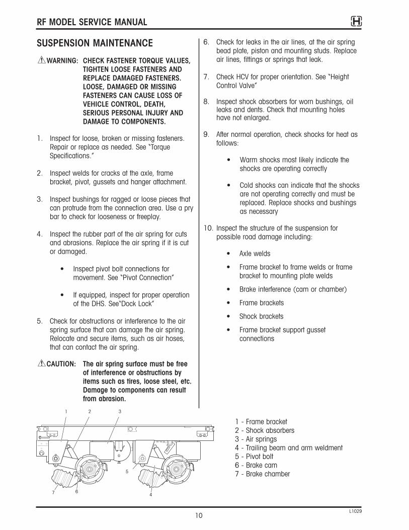
SUSPENSION MAINTENANCE
WARNING: CHECK FASTENER TORQUE VALUES,TIGHTEN LOOSE FASTENERS ANDREPLACE DAMAGED FASTENERS.LOOSE, DAMAGED OR MISSINGFASTENERS CAN CAUSE LOSS OFVEHICLE CONTROL, DEATH,SERIOUS PERSONAL INJURY ANDDAMAGE TO COMPONENTS.
1. Inspect for loose, broken or missing fasteners.Repair or replace as needed. See “TorqueSpecifications.”
2. Inspect welds for cracks at the axle, framebracket, pivot, gussets and hanger attachment.
3. Inspect bushings for ragged or loose pieces thatcan protrude from the connection area. Use a prybar to check for looseness or freeplay.
4. Inspect the rubber part of the air spring for cutsand abrasions. Replace the air spring if it is cutor damaged.
• Inspect pivot bolt connections formovement. See “Pivot Connection”
• If equipped, inspect for proper operationof the DHS. See“Dock Lock”
5. Check for obstructions or interference to the airspring surface that can damage the air spring.Relocate and secure items, such as air hoses,that can contact the air spring.
CAUTION: The air spring surface must be freeof interference or obstructions byitems such as tires, loose steel, etc.Damage to components can resultfrom abrasion.
6. Check for leaks in the air lines, at the air springbead plate, piston and mounting studs. Replaceair lines, fittings or springs that leak.
7. Check HCV for proper orientation. See “HeightControl Valve”
8. Inspect shock absorbers for worn bushings, oilleaks and dents. Check that mounting holeshave not enlarged.
9. After normal operation, check shocks for heat asfollows:
• Warm shocks most likely indicate theshocks are operating correctly
• Cold shocks can indicate that the shocksare not operating correctly and must bereplaced. Replace shocks and bushingsas necessary
10. Inspect the structure of the suspension forpossible road damage including:
• Axle welds
• Frame bracket to frame welds or framebracket to mounting plate welds
• Brake interference (cam or chamber)
• Frame brackets
• Shock brackets
• Frame bracket support gussetconnections
1 2 3
5
7 64
1 - Frame bracket2 - Shock absorbers3 - Air springs4 - Trailing beam and arm weldment5 - Pivot bolt6 - Brake cam7 - Brake chamber
1 2 3
7 6
5
4

RF MODEL SERVICE MANUAL
11L1029
PRESSURE PROTECTION VALVE
The pressure protection valve (PPV) is located at theair reservoir. It supplies the ride height valve with airpressure and protects the system reservoir from beingcompletely drained in the event of a failure in the airsuspension allowing the brake system to remainoperational.
To test, remove outlet line to the ride height valve.With system pressure above 75 psig, air should flowthrough the PPV, at system pressure below 75 psigthe PPV will automatically close and stop air flowfrom the supply tank.
If air continues to flow and drain the air supply tankor does not function properly, replace the PPV.
WARNING: NEVER REMOVE THE PPV FROM THESYSTEM OR SUPPLY AIR DIRECTLYTO THE HEIGHT CONTROL VALVEFROM THE RESERVOIR BYBYPASSING THE PPV.
PRESSUREPROTECTIONVALVE

RF MODEL SERVICE MANUAL
12L1029
DUMP VALVE (IF EQUIPPED)
Dump valves are used to maintain rigid vertical trailerfloor height during loading and unloading. Whendumping, the valve exhausts air from the air springsand lowers the suspension to the bump stops, whichare approximately 21/2 in lower than the ride height.
CAUTION: Failure to inflate the trailersuspension before operating canresult in damage to the suspensionand/ components.
HEIGHT CONTROL VALVE
TEST PROCEDURE
1. Park the unloaded vehicle on a level surface.
2. Secure the vehicle and block the wheels.
3. Disconnect the height control linkage.1 – Lever arm, ride height2 – Linkage, height control3 – Valve, height control
WARNING: VERIFY THAT PEOPLE ARE CLEAR OFTHE TRAILER BEFORE INFLATING ORDEFLATING THE AIR SPRINGS. THEAIR SUSPENSION HAS VARIOUSPINCH POINTS THAT CAN CAUSESERIOUS INJURY.
4. Check the air supply to the height control valve.A minimum of 75 psig (5.2 bar) is typicallyrequired to correctly test the height control valve.
5. Rotate the lever up 30- to 45-degrees. With adelay style valve, air should begin to flow intothe air springs between two and six seconds.Non–delay height control valves begin airflow or exhaust in less than one second.
6. Rotate the lever to the neutral position. Airflowshould stop.
7. Rotate the lever down 30- to 45-degrees. Airshould begin to flow out of the air springsexhausting at the height control valve in two tosix seconds for a delay–style valve. Non-delayheight control valves begin air flow or exhaust in less than one second.
8. Rotate the lever to the neutral position. Airflowshould stop.
CAUTION: Do not add lubrication or cleaningsolvents to the air system. Theseadditives can contaminate the airsystem.
9. If the air does not flow to and from the airsprings, drain the air from the system.Disconnect air lines to the height control valve.Use compressed air to clean the screens in thesupply and delivery ports of the height controlvalve.
10. Connect the air lines to the height control valveand repeat steps 4-8. If air still does not flow toand from the air springs, or if the airflow cannotbe stopped in the neutral position, replace theheight control valve.
11. Inspect the height control valve for air leaks andcracked lever arm housing. If air leaks or cracksare detected, replace the height control valve.
PIVOT POINT CHECK, HEIGHT CONTROL LINKAGE
1. Verify that the pivot points rotate freely (do not bind).
CAUTION: Failure of the pivot points to rotatefreely about the fastener will resultin damage to the linkage, bracketsor suspension.
2. Verify the ends are secure. Loose ends will slipallowing the suspension to raise or lower beyondthe ride height settings.
1
23

RF MODEL SERVICE MANUAL
13L1029
HEIGHT CONTROL VALVEREPLACEMENT PROCEDURE
WARNING: TO PREVENT SERIOUS EYE INJURY, ALWAYS WEAR SAFE EYEPROTECTION WHEN YOU PERFORMVEHICLE MAINTENANCE ORSERVICE.
Replace worn or damaged components with genuinereplacement parts. Installation of non-genuine partscan cause serious personal injury and damage tocomponents.
WARNING: VERIFY THAT PEOPLE ARE CLEAR OFTHE TRAILER BEFORE INFLATING ORDEFLATING THE AIR SPRINGS. THEAIR SUSPENSION HAS VARIOUSPINCH POINTS THAT CAN CAUSESERIOUS PERSONAL INJURY.
1. Park the unloaded vehicle on a level surface.
2. Secure and block the wheels.
3. Drain all air from the supply tank and airsprings. Exhaust air from the system by openingthe drain valve at the bottom of the supply airtank to remove supply air pressure.
4. Remove air supply and delivery lines from theheight control valve to be replaced.
5. Disconnect the linkage. Inspect for damage andreplace bent or damaged linkage.
6. Detach the height control valve from the bracket.
7. Note location and orientation of fittings in heightcontrol valve. Remove fittings from valve.
8. Apply thread sealant to the pipe threads of thefittings and install in valve. Orient the fittings tothe noted position.
9. Attach the new height control valve to themounting bracket. Tighten the mounting bolts(96-144 in. lbs. [11-16 N•m]).
10. Insert the locating pin in the lever arm of theheight control valve (See “Locating Pin Hole” onthe following page).
11. Reconnect the lower linkage pivot. Tighten thelower linkage bolt (96-144 in. lbs. [11-16N•m]).
12. Reattach the air supply and delivery lines.
13. Recharge air system to a minimum of 75 psig(5.2 bar). Avoid sharp bends in airlines. Allconnections must be free of leaks.
14. Using a soapy spray solution, check the entiresystem for air leaks.
15. Remove the locating pin at the lever arm of theheight control valve.
16. Check ride height and adjust as described in“Ride Height Adjustment.”
1
23
RF MODEL SERVICE MANUAL
14L1029
RIDE HEIGHT ADJUSTMENT
WARNING: OVERALL TRAILER HEIGHT ORCARGO HEIGHT MUST NOT EXCEED 13.50 FT. (4114 MM) IFVEHICLE CANNOT CLEAR BRIDGEUNDERPASSES DURING OPERATION,SERIOUS PERSONAL INJURY ANDDAMAGE TO COMPONENTS WILLRESULT.
Ride height adjustment must be done on levelground.
1. Unload the trailer before adjusting the heightcontrol valve. Support the trailer king pin at thenormal operating height.
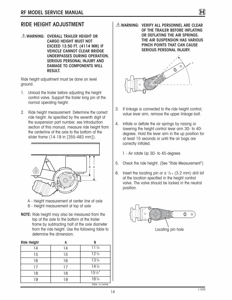
2. Ride height measurement: Determine the correctride height. As specified by the seventh digit ofthe suspension part number, see Introductionsection of this manual, measure ride height fromthe centerline of the axle to the bottom of theslider frame (14-19 in [355-483 mm]).
A - Height measurement at center line of axleB - Height measurement at top of axle
NOTE: Ride height may also be measured from thetop of the axle to the bottom of the trailerframe by subtracting half of the axle diameterfrom the ride height. Use the following table todetermine the dimension.
Ride Height A B
WARNING: VERIFY ALL PERSONNEL ARE CLEAROF THE TRAILER BEFORE INFLATINGOR DEFLATING THE AIR SPRINGS.THE AIR SUSPENSION HAS VARIOUSPINCH POINTS THAT CAN CAUSESERIOUS PERSONAL INJURY.
3. If linkage is connected to the ride height control;value lever arm, remove the upper linkage bolt.
4. Inflate or deflate the air springs by raising orlowering the height control lever arm 30- to 40-degrees. Hold the lever arm in the up position forat least 15 seconds or until the air bags arecorrectly inflated.
1 - Air rotate Up 30- to 45-degrees
5. Check the ride height. (See “Ride Measurement”)
6. Insert the locating pin or a 1/8 in (3.2 mm) drill bitat the location specified in the height controlvalve. The valve should be locked in the neutralposition.
287UX059
AB
287UX050
1
287UX052
1
14 14 111/8
15 15 121/8
16 16 131/8
17 17 141/8
18 18 151/8”
19 19 161/8
Table in inches
Locating pin hole

RF MODEL SERVICE MANUAL
15L1029
7. Loosen the 1/4 in (6.4 mm) adjusting screwlocated on the lever arm body. Allow the leverarm to swing free.
Adjusting screw
8. Align the end of the lever arm to the top openingof the linkage. loosely insert the upper linkagebolt.
9. Tighten the 1/4 in (6.35 mm) adjusting screw.
10. Remove the locating pin or 1/8 in (3.2 mm) drill bit.
WARNING: VERIFY ALL PERSONNEL ARE CLEAROF THE TRAILER BEFORE INFLATINGOR DEFLATING THE AIR SPRINGS.THE AIR SUSPENSION HAS VARIOUSPINCH POINTS THAT CAN CAUSESERIOUS PERSONAL INJURY.
11. Connect the upper linkage bolt. Tighten the boltto 96-144 in. lbs. (11-16 N•m).
1 - Lever arm, ride height2 - Linkage, height control3 - Valve, height control
12. Check to verify that trailer height or cargo heightdoes not exceed 13.50 ft (4114 mm). If rideheight is not within specification, repeat steps 1-10 to adjust ride height. Verify that ride heightis correct.
NOTE: If ride height is correct, then an over-heighttrailer is not the problem of the suspension.Gross over-height should not be corrected bylowering the ride height. At the normalposition, there is only 3 in (76.2 mm) of uptravel.
13. If correct ride height cannot be achieved byperforming Steps 1-11, the linkage will need tobe replaced or modified as required to achievecorrect ride height.
AIR SPRING REPLACEMENT
WARNING: BLOCK THE WHEELS TO PREVENTTHE VEHICLE FROM MOVING.SUPPORT THE VEHICLE WITHSAFETY STANDS. DO NOT WORKUNDER A VEHICLE SUPPORTEDONLY BY JACKS. JACKS CAN SLIPOR FALL OVER. SERIOUS PERSONALINJURY CAN RESULT.
1. Identify the specific air spring that requiresreplacement.
2. Block the tires to prevent forward and backwardmovement of the trailer.
3. Raise and securely support the rear of the trailerwith safety stands.
4. With the trailer raised and securely supported,exhaust all air from the system by opening thevalve at the bottom of the supply air tank.
WARNING: VERIFY ALL PERSONNEL ARE CLEAROF THE TRAILER BEFORE INFLATINGOR DEFLATING THE AIR SPRINGS.THE AIR SUSPENSION HAS VARIOUSPINCH POINTS THAT CAN CAUSESERIOUS PERSONAL INJURY.
1 - Support trailer
2 - Block tires
287UX055
1
1
3
1
2

RF MODEL SERVICE MANUAL
16L1029
5. Remove the ride height valve linkage andexhaust all air from the air springs by movingthe valve arm down.
1 - Air out rotate down 30 to 40-degrees
6. Remove the air inlet line and fitting from thedamaged air spring (see appendix for plumbingdiagram).
7. Remove the nuts from the studs that secure thetop of the air spring.
8. Remove the nut from the bottom of the air spring.The nut can be reached from inside the upperaxle seat or by removing the access plug andusing an extension and socket.
1 - Access plug
9. Compress the air spring. Remove the spring fromthe suspension.
287UX049
1
287UX007
287UX008
1
287UX074
1
23
Upper air spring nut
Lower air spring nutAccess plug

RF MODEL SERVICE MANUAL
17L1029
AIR SPRING INSTALLATION
1. Apply a thread sealant to the pipe plug threadsand install pipe plug into the stud air inlet portnot used to inflate spring. Tighten to 25-30 lbs.(35-40 N•m) or two to three turns from fingertight.
2. Compress the new air spring. Slide the springinto the space between the axle seat and top plate.
3. Align the air inlet and mounting stud. Insert theminto the holes in the top plate.
1 - Mounting stud2 - Lower nut flange3 - Access plug4 - Upper nut5 - Spacer (if required)6 - Pipe plug
4. Install spacer if originally used.
5. Install the lower nut. Tighten the lower nut to 25-30 lbs. in. (34-41 N•m).
6. Install the nuts on the top of the air spring and tighten. Tighten the nut to 40-45 lbs. in. (54-61 N•m).
7. Install the inlet air line to the fitting on the airspring. Apply a thread sealant to the pipe threads of the fitting and install in the open air spring port.
8. Connect the ride height control valve linkage.Tighten the bolt to 96-144 lbs. in. (11-16 N•m).
9. Close the valve at the bottom of the air tank.Pressurize the air system.
CAUTION: The air spring surface must be freeof interference or obstructions byitems such as tires, loose steel, etc.Damage to components caused byabrasion can result.
10. Check that tires, loose steel, etc. do not interferewith the rubber part of the air spring.
11. Use a soap solution to check the entire systemfor air leaks. Check all the air lines and thecomponents as illustrated in the air systemdiagram. Pay particular attention to the air lineconnections at each component. (See Appendixfor plumbing diagram)
12. Raise the trailer. Remove the safety stands.
13. Verify that the ride height of the trailer is correct.If the ride height is incorrect, adjust the heightcontrol lever arm to obtain the correct ride height.Refer to the trailer OEM’s specifications for thecorrect ride height.
A - Ride height measurement
CAUTION: A minimum 1in tire clearance isrequired when all air springs aredeflated.
4
1
2
3
5
6
287UX066
A

RF MODEL SERVICE MANUAL
18L1029
SHOCK ABSORBER REPLACEMENT
Shock absorbers do not absorb shock, they absorbenergy to prevent suspension oscillation. Shockabsorbers are also used as rebound stops in most air suspensions. The shock absorber limits the stroke of an air spring, which prevents the air springfrom being pulled apart. In some severe service applications, a sock strap is added to additionallyaid in limiting the stroke of an air spring.
SHOCK ABSORBER REMOVAL
1. Remove the upper shock mounting bolt. Discard the fasteners.
2. Remove the lower shock bolt. Discard the fasteners.
3. Remove the shock absorber.
SHOCK ABSORBER INSTALLATION
To install a shock absorber:
1. Install shock with dust cover / bell down.
2. For top mount:
a. Place the shock in the upper bracket.b. Insert the bolt through the bracket and
upper shock mount.c. Install the lock nut.
3. For bottom mount:
a. Place a washer on each side of theshock before inserting bolt.
b. Insert the bolt from each side of the axleand arm assembly.
c. Install washer and nut.
4. Torque top and bottom bolt to 210-235 ft. lbs.(285-319 N•m) from inside.
CAUTION: Do not lift the trailer without the shock absorbers in place. If shock absorbers are not in place,overextension of the air springs will occur. Damage may occur to the over extended air springs.
1 - Top mount2 - Bottom mount
287UX027
1
2

RF MODEL SERVICE MANUAL
19L1029
PIVOT CONNECTION
A correct pivot connection is crucial to the life of the suspension. The pivot fastener must continuallyprovide a sufficient clamp load through the bushingto prevent premature suspension failure.
ADVANTAGE
1 - Lock nut (pivot)2 - Hardened washer3 - Pivot washer4 - Pivot bolt5 - Alignment cam washer6 - Wear washer7 - Pivot bushing
The following illustrations show the proper engagement of the socket, which must be maintained as the bolt is torqued and the head is sheared off (a 1 “impact” should deliver enough torque to shear the head).
The following illustrations show the results that willbe visible to verify that the connection has beensecured properly.
The following illustrations show the results that willbe visible if the shear off procedure has taken placeincorrectly. If this condition is found, even during routine inspections, contact the Hendrickson technicalservice department at 800-455-0043 in the UnitedStates or 800-668-5360 in Canada.
NOTE: It is recommended that a new bolt and nut areused when completing an axle alignment onthe AdVANtage suspension.
5
6
4
2
35
3
7
21
6
1 - Bolt Shaft
2 - Shear Shaft
3 - Socket
4 - Pivot bolt Head
1 - Good Shear Pattern
2 - Bolt Shank
3 - Shear Shaft
4 - Pivot bolt Head
1 - Bad Shear Pattern
2 - Bolt Shank
3 - Shear Shaft
4 - Pivot bolt Head
33
22
1
1
22 4
4
3
3
1
44Bad Shear Pattern Side View
Good Shear Pattern Side View
Good Shear Pattern Diagonal View
1
2 21 1
44
33
CorrectSocket Fully Engaged on Torx Head
IncorrectSocket Not Fully Engaged on Torx Head
12
2
4
5
5
6
6
7
3
3

RF MODEL SERVICE MANUAL
20L1029
PIVOT BUSHING
The pivot bushing has unique properties that will provide years of maintenance-free service. The bushing provides a resilient connection that allows an axle to walk without excessive flexing. The bushing, in conjunction with the rigid axle connection, results in a roll stable suspension design that resists trailer lean independent of the air spring loading.
There are times when a problem, seemingly in thearea of suspension is diagnosed as a failed bushing.Closer inspection typically reveals another componentor a faulty installation is the problem. If a problem isin the area of the suspension, see “Diagnostics,” orcontact the Hendrickson technical service departmentat 800-455-0043 in the United States or 800-668-5360 in Canada.
Re-bushing of a suspension requires the use of abushing removal / installation tool and bushing kit,containing the required components for re-bushing.Contact the Hendrickson technical service department.
BUSHING REMOVAL
1. Support the trailer and exhaust the air from the air springs.
2. Remove the nut from the pivot bolt. Remove the pivot bolt from the suspension and thesuspension bracket. Lower the suspensiontrailing beam down and out of the suspensionframe bracket. Carefully remove the inneralignment cam and the outer alignment cam.Discard the nut bolt and wear spacer.
3. Before any bushing removal is attempted, chalkor scribe the bushing orientation on the beamtube to ensure proper positioning of the bushingfor installation.
NOTE: Bushing voids must be located in the correctposition. Voids must be on a vertical centerlinewhen suspension is at ride height. Alignindexing mark on the suspension beam withan indicator mark on the bushing. If the markis not visible on the beam, be sure to installthe voids in the same location as voids of theremoved bushing.
4. Install a bushing removal tool on the bushingtube at the pivot bushing. The tool must consistof a transition tube to receive the bushing as it isremoved and a remover that fits over the metalbushing bore to press the bushing out.

RF MODEL SERVICE MANUAL
21L1029
WARNING: THE END OF THE TRANSITION TUBEWHICH RECEIVES THE REMOVEDBUSHING WILL ALWAYS BEPOSITIONED AGAINST THESUSPENSION BEAM DURINGBUSHING REMOVAL ANDINSTALLATION. THIS WILL CAUSETHE BUSHING TO ELONGATEDURING EITHER OPERATION.
5. Apply high-pressure lube to the threads of thebushing removal tool hex bolt.
WARNING: DO NOT USE PRESSURE LUBE ONTHE BUSHING. IT IS ONLY TO BEUSED ON THE THREADS OF THE HEXHEAD BOLT.
6. Insert the hex head bolt of the assembled toolthrough the bushing until the transition tube restssquarely on the bushing tube. Slide the removerover the exposed threads on the hex head bolt.Snug the hex head bolt while ensuring thetransition tube rests squarely on the bushingtube.
7. Turn the hex head bolt clockwise using 3/4 in.impact wrench and a heavy-duty (Six-point)impact socket. If the bolt stops turning during theremoval process, reverse the impact wrench andloosen the tool assembly. Check parts fordamage. Reset the remover and try again.
NOTE: Use of a one in. impact wrench is notrecommended. Damage to the threads of thehex head bolt could result.
NOTE: Ensure the transition tube remains properlyseated against the bushing during bushingremoval.
NOTE: As a last resort, a small amount of heat maybe required to break the bushing loose. Do notoverheat the bushing tube. Allow the bushingtube to cool before installing the new bushing.
8. Typical removal time should be four minutes orless.
9. After bushing removal, reverse the impact wrenchto disassemble the tool.
1
2
287UX062
Transition tube
Remover
RF MODEL SERVICE MANUAL
22L1029
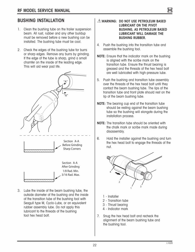
BUSHING INSTALLATION
1. Clean the bushing tube on the trailer suspensionbeam. All rust, rubber and any other buildupmust be removed before a new bushing can beinstalled. The bushing tube must be cool.
2. Check the edges of the bushing tube for burrs or sharp edges. Remove any burrs by grinding. If the edge of the tube is sharp, grind a smallchamfer on the inside of the leading edge. This will aid wear pad life.
3. Lube the inside of the beam bushing tube, theoutside diameter of the bushing and the inside of the transition tube of the bushing tool withSeagull type M, Cyclo-Lube, or an equivalentrubber assembly lube. Do not apply thislubricant to the threads of the bushing tool hex head bolt.
WARNING: DO NOT USE PETROLEUM BASEDLUBRICANT ON THE PIVOTBUSHING, AS PETROLEUM BASEDLUBRICANT WILL DAMAGE THEBUSHING RUBBER.
4. Push the bushing into the transition tube andassemble the bushing tool.
NOTE: Ensure that the indicator mark on the bushingis aligned with the scribe mark on thetransition tube. Ensure the thrust bearing isgreased and the threads of the hex head boltare well lubricated with high-pressure lube.
5. Push the bushing and transition tube assemblyover the threads of the hex head bolt until theycontact the beam bushing tube. The lips of thetransition tube and front plate should rest on thelip of the beam bushing tube.
NOTE: The bearing cup end of the transition tubeshould be resting against the beam bushingtube so the bushing will elongate during theinstallation process.
NOTE: The transition tube should be oriented with the chalk mark or scribe mark made duringdisassembly.
6. Hold the installer against the bushing and turnthe hex head bolt to engage the threads of thenut.
1 - Installer2 - Transition tube3 - Thrust bearing4 - Indicator mark
7. Snug the hex head bolt and recheck thealignment of the beam bushing tube and the bushing tool.
“A”
Section “A-A”Before GrindingSharp Corners
“A”
Section “A-A”After Grinding1/8 Rad. Min.
3/16 Rad. Max.
1 3
2
4
RF MODEL SERVICE MANUAL
23L1029
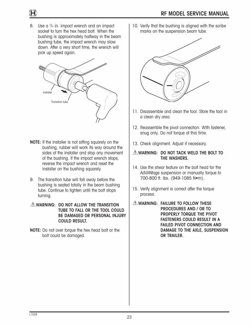
8. Use a 3/4 in. impact wrench and an impact socket to turn the hex head bolt. When thebushing is approximately halfway in the beambushing tube, the impact wrench may slowdown. After a very short time, the wrench willpick up speed again.
NOTE: If the installer is not sitting squarely on thebushing, rubber will work its way around thesides of the installer and stop any movementof the bushing. If the impact wrench stops,reverse the impact wrench and reset theinstaller on the bushing squarely.
9. The transition tube will fall away before thebushing is seated totally in the beam bushingtube. Continue to tighten until the bolt stopsturning.
WARNING: DO NOT ALLOW THE TRANSITIONTUBE TO FALL OR THE TOOL COULDBE DAMAGED OR PERSONAL INJURYCOULD RESULT.
NOTE: Do not over torque the hex head bolt or thebolt could be damaged.
10. Verify that the bushing is aligned with the scribemarks on the suspension beam tube.
11. Disassemble and clean the tool. Store the tool ina clean dry area.
12. Reassemble the pivot connection. With fastener,snug only. Do not torque at this time.
13. Check alignment. Adjust if necessary.
WARNING: DO NOT TACK WELD THE BOLT TOTHE WASHERS.
14. Use the shear feature on the bolt head for theAdVANtage suspension or manually torque to700-800 ft. lbs. (949-1085 N•m).
15. Verify alignment is correct after the torqueprocess.
WARNING: FAILURE TO FOLLOW THESEPROCEDURES AND / OR TOPROPERLY TORQUE THE PIVOTFASTENERS COULD RESULT IN AFAILED PIVOT CONNECTION ANDDAMAGE TO THE AXLE, SUSPENSIONOR TRAILER.
1
2
Transition tube
Installer

RF MODEL SERVICE MANUAL
24L1029
SUSPENSION AXLE ALIGNMENT
WARNING: ALIGNMENT SHOULD ALWAYS BEDONE WHILE THE TRAILER ISEMPTY.
Proper preparation is a must for effective axle alignment. The vehicle, tools, equipment and worksite must all be appropriate for axle alignment. Theprocess also requires a trained technician who knowsthe specifications.
Axle alignment specifications may be stated in inches, degrees, minutes of angle (MOA or 1/60 of a degree) or mm/M. Each format can productequivalent results. Hendrickson trailer axles are builtto less than +/- 2.5 MOA run out at each spindle.
ADJUSTMENTS
TMC RP 708, Trailer Axle alignment, addresses all the steps needed to make the trailer ready foralignment.
To review these:
• Inspect the suspension and the axles forany obvious damage
• Tighten, repair or replace any parts that do not meet suspension or axlemanufacturer criteria for serviceability
• Check tires for proper inflation andmatching diameters
• Park the trailer on a smooth and levelpad with the parking brakes released
NOTE: After backing the trailer in, pull it forward in astraight line to gentle a stop. This will allowsuspension parts to settle in a forward runningposition. Use wheel chocks to prevent injury due to accidental movement of the trailer.
• With the brakes still released, adjust theheight control valve for the proper settingand the upper coupler (bolster plate) to theproper height by raising or lower thelanding gear legs
• Do not proceed unless the wheel bearingend play is known to be in adjustment per TMC's recommended procedure, thebearing manufacturer, and / orHendrickson Publication L496, Wheel End Maintenance Procedures,available at www.hendrickson-intl.com
Measure the distance from the trailer king pin to the centerline of the spindles on the first axle. It is recommended that a spindle extension be utilized.Dimensions A and B must be equal within 1/8 in (3.2mm). Dimension E is equal to the distance betweenthe trailer centerline and the axle centerline.Repeated difficulty in adjusting the axle to the desired reading is most often due to a loose wheelbearing, badly worn suspension component ora combination.
WARNING: NEVER BEND THE AXLE IN ORDERTO CORRECT ANY ALIGNMENTCONDITION. THIS COULD WEAKENTHE AXLE AND CAUSE AXLE FAILURERESULTING IN SERIOUS INJURY ORDEATH.
1. The trailer must be on a level surface.
2. Adjust the trailer landing gear. The height of theking pin should be the same as when the traileris connected.
3. Release the parking brakes. Secure and block thewheels of the axle not being aligned to keep thelocking pins tight against the same side of thebody railholes (front and rear).
C
DE
A
A = B ± 1/8" (3mm)
C = D ± 1/16" (1.5mm)
E < 1/16" (1.5mm)
B
287UX071
A = B + 1/8 in (3mm)
A = B < 1/8 in (1.5mm)
C = D + 1/16 in (1.5mm)
RF MODEL SERVICE MANUAL
25L1029
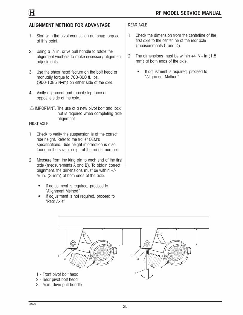
ALIGNMENT METHOD FOR ADVANTAGE
1. Start with the pivot connection nut snug torquedat this point.
2. Using a 1/2 in. drive pull handle to rotate thealignment washers to make necessary alignmentadjustments.
3. Use the shear head feature on the bolt head ormanually torque to 700-800 ft. lbs. (950-1085 N•m) on either side of the axle.
4. Verify alignment and repeat step three onopposite side of the axle.
IMPORTANT: The use of a new pivot bolt and lock nut is required when completing axlealignment.
FIRST AXLE
1. Check to verify the suspension is at the correctride height. Refer to the trailer OEM'sspecifications. Ride height information is alsofound in the seventh digit of the model number.
2. Measure from the king pin to each end of the firstaxle (measurements A and B). To obtain correctalignment, the dimensions must be within +/-1/8 in. (3 mm) at both ends of the axle.
• If adjustment is required, proceed to“Alignment Method”
• If adjustment is not required, proceed to“Rear Axle”
REAR AXLE
1. Check the dimension from the centerline of thefirst axle to the centerline of the rear axle(measurements C and D).
2. The dimensions must be within +/- 1/16 in (1.5mm) at both ends of the axle.
• If adjustment is required, proceed to“Alignment Method”
287UX069
13
23
41 - Front pivot bolt head2 - Rear pivot bolt head3 - 1/2 in. drive pull handle

RF MODEL SERVICE MANUAL
26L1029
DIAGNOSTICS
The following tables provide information to aid indetermining the root cause of a trailer suspensionsystem problem.
Condition Possible Cause Recommended Action
All air springs flat
Insufficient air pressure in reservoir toallow the PPV to supply the RH valve.
Build air pressure to 75 psig (5.2 bar) or more. Check compressor for correct function. Check all air lines and fittings forleaks.
Defective pressure protection valve. Check and replace valve if necessary.
Height control valve supply or delivery fitting clogged.
Inspect height control valve supply and deliveryfittings for restrictions.
Air leak in system.Inspect entire system for leaks. Repair orreplace as necessary.
Suspension overloaded. Review load to suspension rated capacity.
Air springs fully raised butdon’t exhaust
Height control valve delivery port ofexhaust port plugged.
Inspect ports for restrictions. Repair or replaceas necessary.
Height Control linkage broken. Replace linkage.
Defective RH control valve. Replace RH valve.
Vehicle body incorrect rideheight during operation
Height control valve not adjustedproperly.
Inspect and adjust as necessary.
Height control lever bent or broken. Replace lever.
Insufficient air pressure to the suspensionsystem (low-ride-height condition).
Check air compressor and pressure protectionvalve for proper operation. Inspect system forleaks. Repair or replace as necessary.
Main air pressure drops65 psi (88 kPa) andlower
Ruptured air spring. Inspect air springs and replace as necessary.
Defective or inoperative PPV valve. Inspect and replace as necessary.
Leaking air lines.Inspect air lines and repair or replace as necessary.
Hard rideImproper ride height or air springs flat.
Check and adjust ride height. See first condition.
DHS engaged (DHS equipped units only).Verify operation of DHS when parking brake isreleased.
Suspension ride height notmaintained duringoperation
Clogged air filters. Inspect, clean or replace as necessary.
Moisture in air tank.Drain air tank and evacuate air system of moisture.
Clogged filter screens in height controlvalve.
Inspect, clean or replace as necessary.
Damaged linkage or incorrect valvemounting.
Replace, repair or adjust as necessary.
Defective RH control valve. Replace RH valve.

RF MODEL SERVICE MANUAL
27L1029
Condition Possible Cause Recommended Action
Incorrect tire clearance in full jounce Incorrect tire size. Replace tires with the recommended tire size.
Trailer not pulling straight (dog walk)Trailer axles out of alignment. Realign axles.
Loose pivot bolts.Align axles; replace and tighten alignment boltsto the proper torque.
Trailer wandering or unusual rattling
Worn bushings. Inspect bushings and replace as needed.
Loose pivot bolts.Align axles; replace and tighten alignment boltsto the proper torque.
RF MODEL SERVICE MANUAL
28L1029
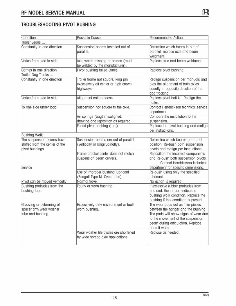
TROUBLESHOOTING PIVOT BUSHING
Condition Possible Cause Recommended ActionTrailer Leans ...Constantly in one direction Suspension beams installed out of Determine which beam is out of
parallel. parallel, replace axle and beam weldment.
Varies from side to side Axle welds missing or broken (must Replace axle and beam weldment.be welded by the manufacturer).
Carries in one direction Pivot bushing failed (rare). Replace pivot bushing.Trailer Dog Tracks ...Constantly in one direction Trailer frame not square, king pin Realign suspension per manuals and
excessively off center or high crown bias the alignment of both axles highways. equally in opposite direction of the
dog tracking.Varies from side to side Alignment collars loose. Replace pivot bolt kit. Realign the
trailer.To one side under load Suspension not square to the axle. Contact Hendrickson technical service
department.Air springs (bag) misaligned. Compare the installation to the drawing and reposition as required. suspension.Failed pivot bushing (rare). Replace the pivot bushing and realign
per instructions.Bushing WalkThe suspension beams have Suspension beams are out of parallel Determine which beams are out of shifted from the center of the (vertically or longitudinally). position. Re-bush both suspension pivot bushings pivots and realign per instructions .
Frame bracket center does not match Reposition the incorrect components suspension beam centers. and Re-bush both suspension pivots.
Contact Hendrickson technicalservice department for specific dimensions.
Use of improper bushing lubricant Re-bush using only the specified (Seagull Type M, Cyclo-lube). lubricant.
Pivot can be moved vertically Normal travel. No action is required.Bushing protrudes from the Faulty or worn bushing. If excessive rubber protrudes from bushing tube one end, then it can indicate a
bushing walk condition. Replace the bushing if this condition is present.
Grooving or deforming of Excessively dirty environment or fault The wear pads act as filler piecesspacer arm wear washer worn bushing. between the hanger and the bushing.tube and bushing The pads will show signs of wear due
to the movement of the suspension beam during articulation. Replace pads if worn.
Wear washer life cycles are shortened Replace as needed.by wide spread axle applications.

RF MODEL SERVICE MANUAL
29L1029
TORQUE SPECIFICATIONS
WARNING: CHECK FASTENER TORQUE VALUES,TIGHTEN LOOSE FASTENERS ANDREPLACE DAMAGED FASTENERS.LOOSE, DAMAGED OR MISSINGFASTENERS CAN CAUSE LOSS OFVEHICLE CONTROL, DEATH,SERIOUS PERSONAL INJURY, ANDDAMAGE TO COMPONENTS.
• Check fastener torque values after 1,000miles (1,600 km) and annually thereafter
• Retighten loose fasteners
• Replace damaged fasteners to maintain correct torque values and comply with warranty requirements
Fasteners in. lbs. ft. lbs. N•mUpper air spring nut - 40-45 54-61Lower air spring - 25-30 34-41Shock absorber-upper and lower - 210-235 285-319Air chamber mounting nuts - 100-115 136-156Cam tube assembly flange bolt - 65-85 88-115Pivot bolt (11/8" dia.) - 700-800 950-1085AdvantageHaldex Automatic Brake Adjuster - 8-12 11-16control arm nutRide height valve fastener 96-144 - 11-16Ride height valve linkage fastener 96-144 - 11-16Slider hold down clip - 80 110Dock lock air bag - 8-12 11-16Dock lock pivot brackets - 65-75 89-103Dust shield mounting bolt 180-200 - 20-23
Torque Specifications Table

RF MODEL SERVICE MANUAL
30L1029
APPENDIX
TYPICAL TRAILER SUSPENSION AIR SYSTEM
287UX028
Ride Height Valve
PressureProtection
Valve
Drain Cock
Supply Air Tank
Air Spring
Air Spring Air Spring
Air Spring
SUPPLY
PILOT TOATMOSPHERE
SUSP

RF MODEL SERVICE MANUAL
31L1029
TYPICAL TRAILER SUSPENSION AIR SYSTEMWITH MANUAL DUMP VALVE
- Operator can manually deflate air springsallowing the trailer to rest on the air springbumpers, or dock height support, ifequipped
- Operator must manually reset the valve toinflate the air springs
CAUTION: Failure to inflate the trailersuspension before operating canresult in damage to the suspensionand / or components.
287UX028
PILOT
EXHAUST
OUT
Manual Dump Valve
Ride Height Valve
PressureProtection
Valve
Drain Cock
Supply
Suspension
Air Tank
Air Spring
Air Spring Air Spring
Air Spring
PILOT TOATMOSPHERE

RF MODEL SERVICE MANUAL
32L1029
TYPICAL TRAILER SUSPENSION AIR SYSTEMWITH AUTO DUMP RIDE HEIGHT VALVE
SUPPLY LINE DE-ENERGIZED
- The air springs are de-flated automatically whenthe parking brakes are set, allowing the suspension to rest on the air spring bumpersor DHS, if equipped
NOTE: An empty or lightly loaded trailer may not reston the air spring bumpers until being loaded.Expect a sudden squat of the suspensionunder this condition.
SUPPLY LINE ENERGIZED
- The air springs are re-flated when the parkingbrakes are released
CAUTION: Failure to inflate the trailersuspension before operating canresult in damage to the suspensionand / or components.
287UX029
3/8" Air Line (all)
PressureProtection
Valve
Air Spring
Air Tank
Air Spring Air Spring
Spring BrakeControl Valve
3/8" Air Line
Air Spring
Drain Cock
Ride Height Valve
PILOT
SUPPLYSUPPLY
SUSP
PLUG
Supply Line (Emergency)

RF MODEL SERVICE MANUAL
33L1029
TYPICAL TRAILER SUSPENSION WITHMANUAL DUMP VALVE WITH AUTO RESET
- Operator can manually deflate air springs allowing the trailer to rest on the air springbumpers, or dock lock, if equipped
- With the auto refill feature, air springs re-inflatewhen supply line is energized
287UX029
3/8" Air Line (all)
PressureProtection
Valve
FrontDriver Side
Air Bag
Air Tank
FrontCurb Side
Air Bag
RearCurb Side
Air Bag
Spring BrakeControl Valve
3/8" Air Line
RearDriver Side
Air Bag
Drain Cock
Ride Height Valve
SUPPLY
DUMP
SUSP
PILOT TOATMOSPHERE
Supply Line (Emergency)
INOUT
PILOT
Manual Dump /Auto Reset Valve

www.hendrickson-intl.com
Information contained in this literature was accurate at the time of publication. Product changes may have been made after the copyright date that are not reflected.© 2009 Hendrickson USA, L.L.C. (U.S. Rights) Hendrickson International Corporation (Rights Outside U.S.) All Rights ReservedL1029 1-09
Trailer Suspension Systems250 Chrysler Drive, Unit #3Brampton, ON Canada L6S 6B6 905.789.1030Fax 905.789.1033
Trailer Suspension SystemsAv. Industria Automortriz #200Parque Industrial Stiva AeropuertoApodaca, N.L., México C.P. 66600 (52) 81 8288 1300Fax (52) 81 8288 1301
Trailer Suspension Systems2070 Industrial Place SECanton, OH 44707-2641 USA
866.RIDEAIR (743.3247)330.489.0045Fax 800.696.4416
Printed in United States of America


