


Ecological & Economical SK Series Ball Screw
Roller Guideways
Single Axis Robot Positioning Guideways
www.atlantagmbh.de
Leader in Servo Drive Systems
Motorised Linear ActuatorRack & Pinion
Servo Worm Gear Box
Planetary Gear Units
Motion Control and System Technology
RobotLinear Actuator
Strong Line Racks

These products are widely used by popular manufacturers in fields of
1 Machine Tools
1 Measuring / Inspection Machines
1 SPM’s
1 Welding Automation
1 Robotics
1 Diamond Processing
1 Electronics
1 Semi Conductor
1 Solar
1 Aero-Space
1 Printing
1 Painting
1 Pharmaceutical
1 Medical
1 Food Processing Machinery
1 Packaging
1 Textile
1 Factory Automation
1 Pick & Place Units
1 General Engineering Industry &
similar related Industrial Machineries.


7
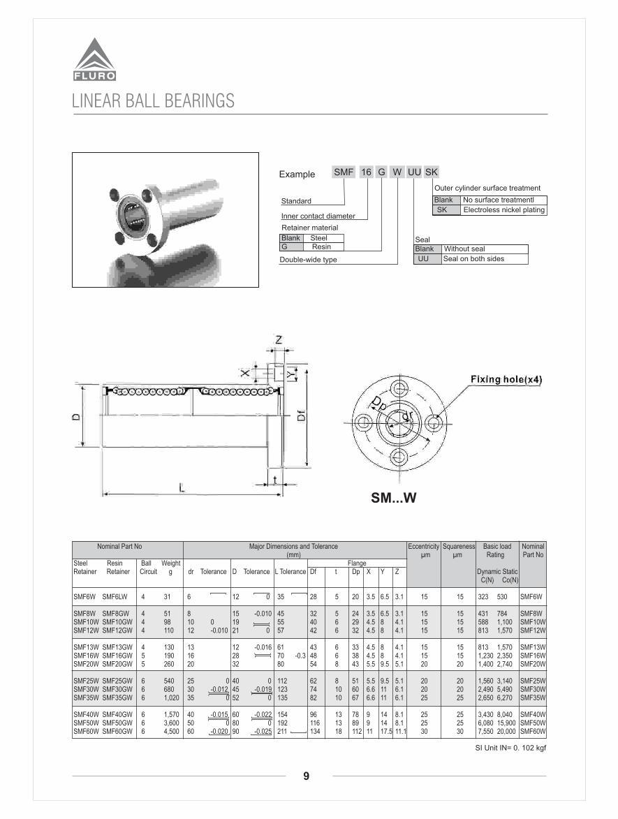
16SMF G SK
Standard
Inner contact diameter
Retainer material
Blank Steel
G Resin
Outer cylinder surface treatmentBlank No surface treatment
SK Electroless nickel plating
Seal
UUExample
Blank Without seal
UU Seal on both sides
LINEAR BALL BEARINGS
SI Unit IN= 0. 102 kgf
SMF

8
16SMK G SK
Standard
Inner contact diameter
Retainer material
Blank Steel
G Resin
Outer cylinder surface treatmentBlank No surface treatment
UU Electroless nickel plating
Blank Without seal
UU Seals on both side
seal
UU
LINEAR BALL BEARINGS
SI Unit IN= 0. 102 kgf
SMF
9
16SMF G UU
Standard
Inner contact diameter
Retainer material
Blank SteelG Resin
SealBlank Without seal
Outer cylinder surface treatment
WExample SK
UU Seal on both sidesDouble-wide type
Blank No surface treatmentl
SK Electroless nickel plating
LINEAR BALL BEARINGS
SI Unit IN= 0. 102 kgf
SM...W

10
Nominal Part No Major Dimensions and Tolerance Eccentricity Squareness Basic load Nominal (mm) µm µm Rating Part NoSteel Resin Ball Weight FlangeRetainer Retainer Circuit g dr Tolerance D Tolerance L Tolerance Df t Dp X Y Z Dynamic Static C(N) Co(N)
SMK 6W SMK 6GW 4 25 6 12 0 35 28 5 20 3.5 6.5 3.1 15 15 323 530 SMK 6W
SMK 8W SMK 8GW 4 43 8 15 -0.010 45 32 5 24 3.5 6.5 3.1 15 15 431 784 SMK 8WSMK10W SMK10GW 4 78 10 0 19 55 40 6 29 4.5 8 4.1 15 15 588 1,100 SMK10WSMK12W SMK12GW 4 90 12 -0.010 21 0 57 42 6 32 4.5 8 4.1 15 15 813 1,570 SMK12W
SMK13W SMK13GW 4 108 13 12 0.016 61 43 6 33 4.5 8 4.1 15 15 813 1,570 SMK13WSMK16W SMK16GW 5 165 16 28 70 -0.3 48 6 38 4.5 8 4.1 15 15 1,230 2,350 SMK16WSMK20W SMK20GW 5 225 20 32 80 54 8 43 5.5 9.5 5.1 20 20 1,400 2,740 SMK20W
SMK25W SMK25GW 6 500 25 0 40 0 112 62 8 51 5.5 9.5 5.1 20 20 1,560 3,140 SMK25WSMK30W SMK30GW 6 590 30 -0.012 45 -0.019 123 74 10 60 6.6 11 6.1 20 20 2,490 5,490 SMK30WSMK35W SMK35GW 6 930 35 0 52 0 135 82 10 67 6.6 11 6.1 25 25 2,650 6,270 SMK35W
SMK40W SMK40GW 6 1,380 40 -0.015 60 -0.022 154 96 13 78 9 14 8.1 25 25 3,430 8,040 SMK40WSMK50W SMK50GW 6 3,400 50 0 80 0 192 116 13 89 9 14 8.1 25 25 6,080 15,900 SMK50WSMK60W SMK60GW 6 4,060 60 -0.020 90 -0.025 211 134 18 112 11 17.5 11.1 30 30 7,550 20,000 SMK60W
16SMK G UU
Standard
Inner contact diameter
Retainer material
Blank Steel
G ResinSealBlank Without seal
Outer cylinder surface treatment
WExample SK
UU Seals on both sidesDouble-wide type
Blank No surface treatmentl
SK Electroless nickel plating
LINEAR BALL BEARINGS
SI Unit IN= 0. 102 kgf
SMK...W

11
LM SLIDE UNITSLM
Model No. Shaft
Diameterd
Dimensions of Assembly Dimensions of Block
AHC - 16
AHC - 20
AHC - 25
AHC - 40
16
20
25
40
45
50
60
90
27.1
27.1
32.5
47
45
48
60
90
45
50 35
65 40
90 65
32
35
40
65
9
11
14
22
30 M5
M10
33
72
H h W L1 B C t1 S1 T
20
l
AHC - 30 30 70 36.6 70 70 5050 16.8 M8 5618
M639
47
12
±0.2
W2
±0.2
S2 t2
l
h
t1
B S1
H
W
d
AHC - 50 50 120 67 119.3 110 8094 25 M10 9127
L1
C
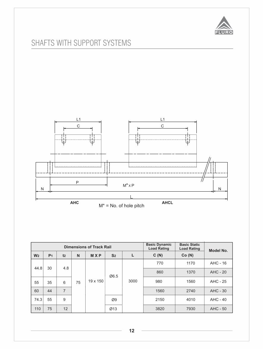
SHAFTS WITH SUPPORT SYSTEMS
12
AHC AHCLM* = No. of hole pitch
W2 P1 t2 N LModel No.
C (N) Co (N)M X P S2
Dimensions of Track RailBasic Dynamic
Load RatingBasic StaticLoad Rating
AHC - 16770 1170
44.8 30 4.8
Ø6.5AHC - 20860 1370
55 35 6 AHC - 25980 1560
60 44 7 AHC - 301560 2740
74.3 55 9 AHC - 402150 4010Ø9
75
L1
C
M* X PP
N N
110 75 12 AHC - 503820 7930Ø13
300019 x 150
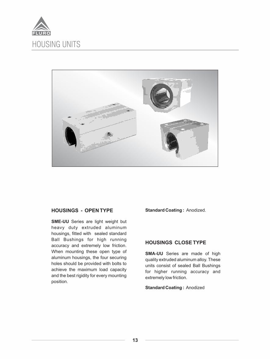
HOUSINGS - OPEN TYPE
SME-UU Series are light weight but
heavy duty extruded aluminum
housings, fitted with sealed standard
Ball Bushings for high running
accuracy and extremely low friction.
When mounting these open type of
aluminum housings, the four securing
holes should be provided with bolts to
achieve the maximum load capacity
and the best rigidity for every mounting
position.
Standard Coating : Anodized.
HOUSINGS CLOSE TYPE
SMA-UU Series are made of high
quality extruded aluminum alloy. These
units consist of sealed Ball Bushings
for higher running accuracy and
extremely low friction.
Standard Coating : Anodized
HOUSING UNITS
13
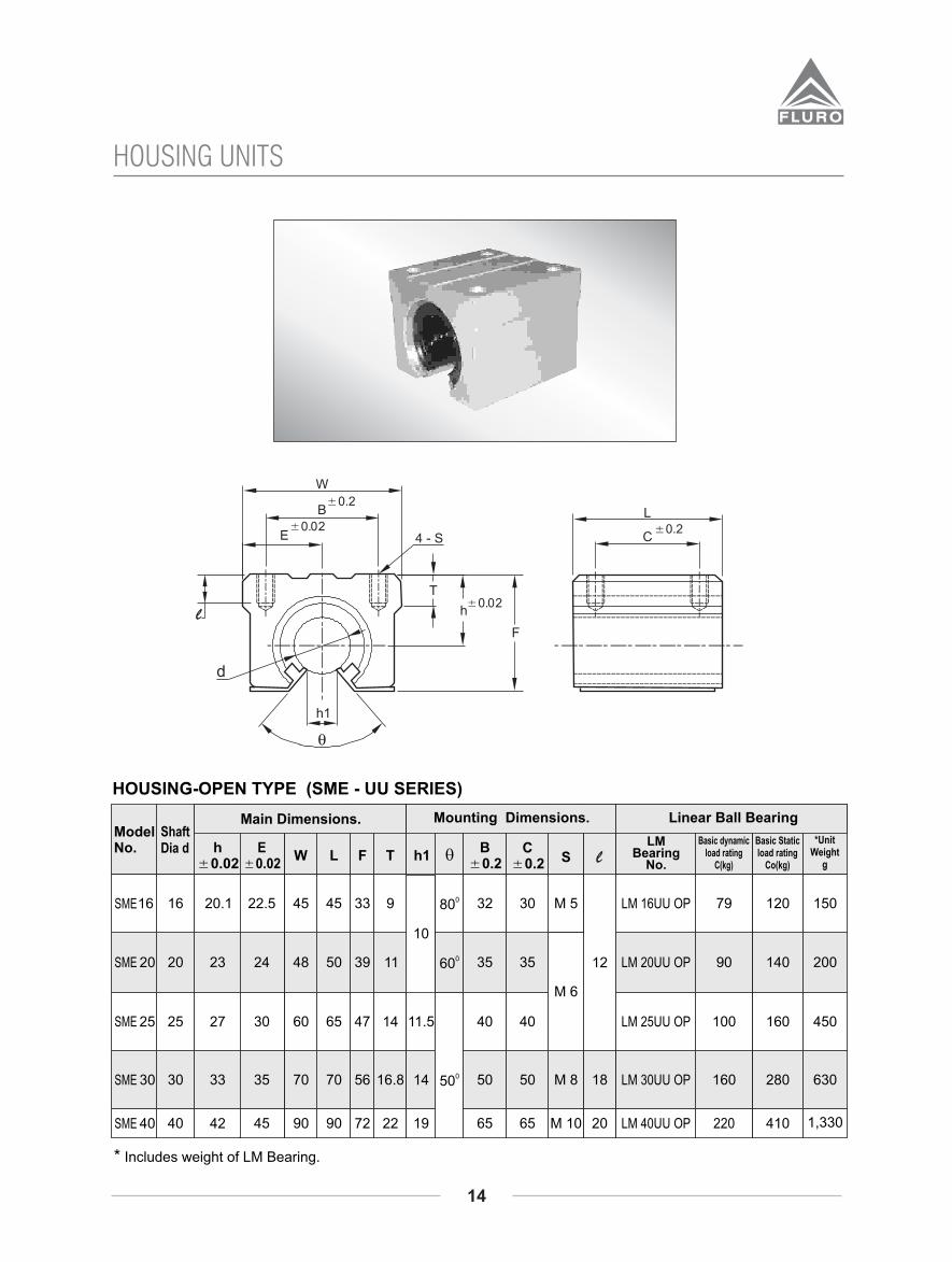
HOUSING-OPEN TYPE (SME - UU SERIES)
16
20
25
30
40
Shaft Dia d
16
20
25
30
40
20.1
23
27
33
42
h A0.02
22.5
24
30
35
45
EA0.02
W
45
48
60
70
90
L
45
50
65
70
90
F
33
39
47
56
72
T
9
11
14
16.8
22
080
060
050
B A0.2
32
35
40
50
65
C A0.2
30
35
40
50
65
S
M 5
M 6
M 8
M 10
12
18
20
LM Bearing
No.
LM 16UU OP
LM 20UU OP
LM 25UU OP
LM 30UU OP
LM 40UU OP
Basic dynamic load rating
C(kg)
79
90
100
160
220
120
140
160
280
410
Basic Static load rating
Co(kg)
150
200
450
630
1,330
*UnitWeight
g
Main Dimensions.
q
Mounting Dimensions.
h1
11.5
14
19
l
Model No.
Linear Ball Bearing
10
* Includes weight of LM Bearing.
HOUSING UNITS
14
SME
SME
SME
SME
SME

ModelNo.
Main Dimensions Mounting Dimensions
E W L F G Th B C K S 1 S 2
LM BearingModel
No.
dynamic C (kg)
static Co (kg)
SMA16
SMA 20
SMA 25
SMA 30
SMA 35
SMA 40
Nominalshaft
diameter
16
20
25
30
35
40
19
21
26
30
34
40
25
27
38
39
45
51
50
54
76
78
90
102
44
50
67
72
80
90
38.5
41
51.5
59.5
68
78
32.5
35
42
49
54
62
9
11
12
15
18
20
36
40
54
58
70
80
34
40
50
58
7
11
10
11
M5
M6
M8
M10
4.3
5.2
7
8.7
12
18
25
LM16UU
LM20UU
LM25UU
LM30UU
LM35UU
LM40UU
79
90
100
160
170
220
120
140
160
280
320
410
200
255
600
735
1100
1590
g
* Unit Weight
l
* Includes weight of LM Bearing.
60
HOUSING-CLOSE TYPE (SMA-UU SERIES)
HOUSING UNITS
15

ModelNo.
Main Dimensions Mounting Dimensions
E W L F G Th B C K S 1 S 2
LM BearingModel
No.
dynamic C (kg)
static Co (kg)
HFL16
HFL20
HFL25
HFL30
HFL35
HFL40
Nominalshaft
diameter
16
20
25
30
35
40
19
21
26
30
34
40
25
27
38
39
45
51
50
54
76
78
90
102
85
96
130
140
155
175
38.5
41
51.5
59.5
68
78
32.5
35
42
49
54
62
9
11
12
15
18
20
36
40
54
58
70
80
60
70
100
110
7
11
10
11
M5
M6
M8
M10
4.3
5.2
7
8.7
12
18
25
LM16UU
LM20UU
LM25UU
LM30UU
LM35UU
LM40UU
125
144
164
250
270
350
240
280
320
560
640
820
400
570
1200
1480
2200
3200
g
* Unit Weight
l
* Includes weight of LM Bearing.
120
HOUSING-CLOSE TYPE (HFL-- UU SERIES)
HOUSING UNITS
16
Grease nipple
±0.2C
L±0.2
B
W
K4-S1
N
±0.02h
G
±0.02E
F
L
4,ØS2
T
140
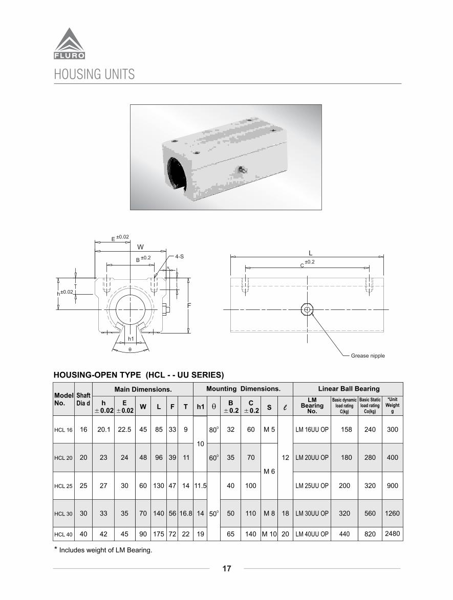
HOUSING-OPEN TYPE (HCL - - UU SERIES)
HCL 16
HCL 20
HCL 25
HCL 30
HCL 40
Shaft Dia d
16
20
25
30
40
20.1
23
27
33
42
h A0.02
22.5
24
30
35
45
EA0.02
W
45
48
60
70
90
L
85
96
130
140
175
F
33
39
47
56
72
T
9
11
14
16.8
22
080
060
050
B A0.2
32
35
40
50
65
C A0.2
60
70
100
110
140
S
M 5
M 6
M 8
M 10
12
18
20
LM Bearing
No.
LM 16UU OP
LM 20UU OP
LM 25UU OP
LM 30UU OP
LM 40UU OP
Basic dynamic load rating
C(kg)
158
180
200
320
440
240
280
320
560
820
Basic Static load rating
Co(kg)
300
400
900
1260
2480
*UnitWeight
g
Main Dimensions.
q
Mounting Dimensions.
h1
11.5
14
19
l
Model No.
Linear Ball Bearing
10
* Includes weight of LM Bearing.
HOUSING UNITS
17
Grease nipple
±0.2C
L±0.2B
W
±0.02E
4-S
N
F
±0.02h
h1
q

SHAFT END SUPPORTS
(SK SERIES) :
Shaft end supports are economical &
made of high quality aluminum alloy
or steel, offering high rigidity and
geometrical accuracy. They are used
for end support of plain shafts.
Standard Coating :
For Aluminum - Anodized
SHAFT SUPPORT RAILS :
Shaft support assemblies prevent
shaft deflection ensuring efficient
running of linear slides and also
saves time and expensive designs by
offering ready to use supports from
stock.
Shaft support rails of series ‘A’ are
made of high quality extruded
aluminum alloy. Mounting holes are
provided at standard pitch.
SUPPORT UNITS
18
19
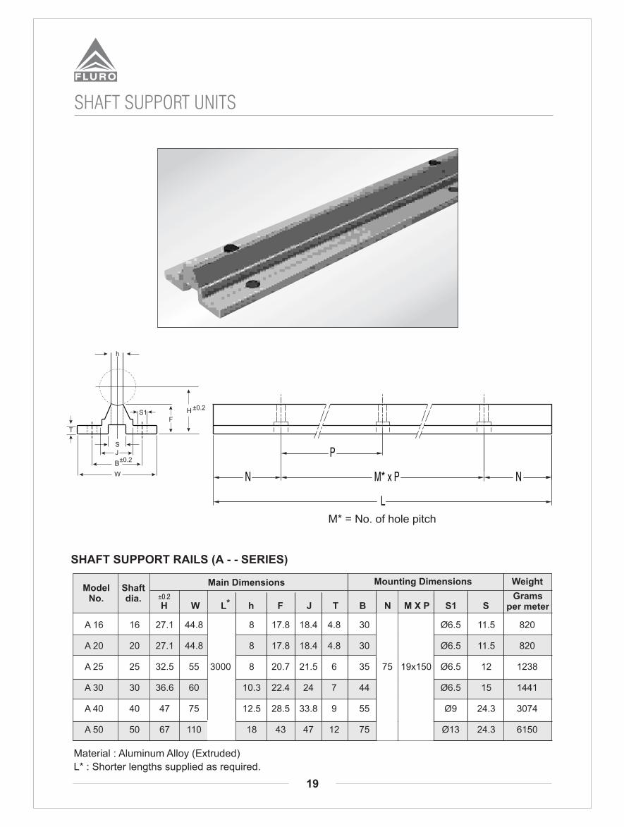
SHAFT SUPPORT UNITS
* H W L h F J T B N M X P S1 S
ModelNo.
Shaft dia.
Main Dimensions Mounting Dimensions Weight
±0.2 Grams per meter
SHAFT SUPPORT RAILS (A - - SERIES)
Material : Aluminum Alloy (Extruded)
L* : Shorter lengths supplied as required.
L
N M* x P
P
N
A 16 16 27.1 44.8 8 17.8 18.4 4.8 30 Ø6.5 11.5 820
A 20 20 27.1 44.8 8 17.8 18.4 4.8 30 Ø6.5 11.5 820
A 25 25 32.5 55 3000 8 20.7 21.5 6 35 75 19x150 Ø6.5 12 1238
A 30 30 36.6 60 10.3 22.4 24 7 44 Ø6.5 15 1441
A 40 40 47 75 12.5 28.5 33.8 9 55 Ø9 24.3 3074
A 50 50 67 110 18 43 47 12 75 Ø13 24.3 6150
±0.2H
T
W
S1F
h
SJ
±0.2B
M* = No. of hole pitch

SHAFT END SUPPORT (SK - SERIES)
Shaftdiameter
d
16
20
25
30
35
40
50
SK 16
SK 20
SK 25
SK 30
SK 35
SK 40
SK 50*
MODELNO W P BL G ØS
48
60
70
84
98
114
126
25
30
38
44
50
60
74
38
45
56
64
74
90
100
44
51
60
70
82
96
120
16
20
24
28
32
36
40
8
10
12
15
18
5.5
6.6
9
11
14
MountingboltN
M5
M6
M8
M10
M12
24
30
35
42
49
57
63
E±0.05
27
31
35
42
50
60
70
h±0.02 F
Lockingbolt
S
M4
M5
M6
M8
M12
UnitWeight
g
40
70
130
180
270
420
750
1��Other sizes upon request. 1��* Check for availability
END SUPPORT UNITS
20
E

21
SPEED GUIDE - EXTERNAL

22
SPEED GUIDE - EXTERNAL
SB-LGA20
SB-LGA25
SB-LGA30
30
32.5
38.5
4
4.5
5.5
63
80
100
92
105
120
53
60
85
40
40
50
M6
M6
M8
8
8
10
20
28
34.2
9
12.5
14.5
5.5
5.5
6.5
5.5
5.5
6.5
19.5
20
24
60
50
50
6
8
10
30
25
25
1020
3000
3000
A
C
FØ D
H1H
T
4 - M
Ø G
PØG1
L1
I
h
L
BE
23
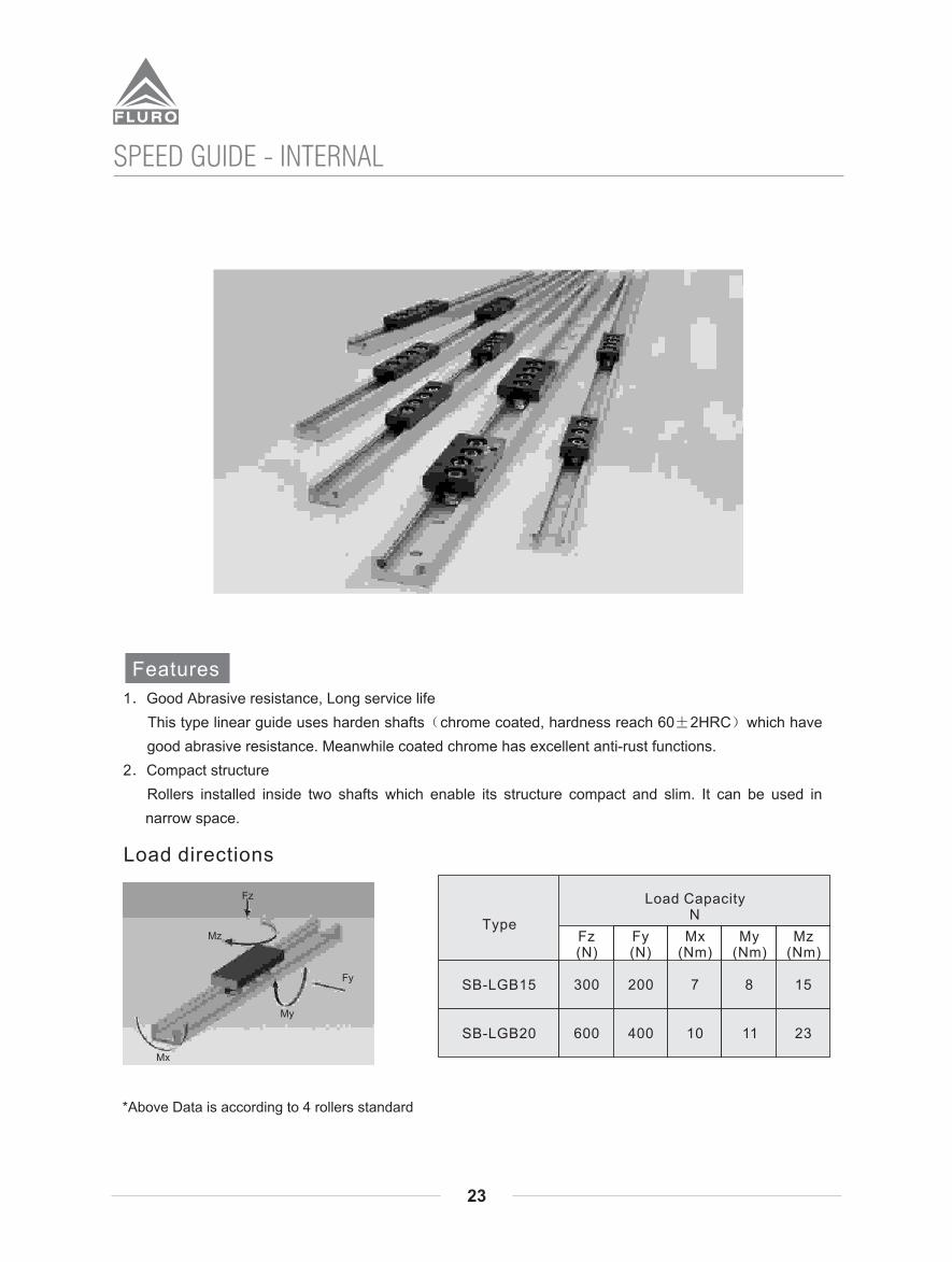
SPEED GUIDE - INTERNAL
*Above Data is according to 4 rollers standard

24
SPEED GUIDE - INTERNAL
L
ØG
ØG1L1
h
H1
H
BE
A W
4-M
P
AssemblyDimensions
(mm)
Carriage Dimensions(mm)
Railway Dimensions(mm)
Type
C
The number of rollers can be adjusted if necessary.

LEAD SCREWS
Trapezoidal screws are precision rolled. Continuous search for improvement and many years of experience in the development of the cold plastic deformation process which characterizes rolling allow us to offer our customers trapezoidal screws with excellent features.
MATERIALS
Steel used in trapezoidal screws
C15E - 1.1141 EN 10084 - C15E
1C45 - 1.0503 EN 10083 - 1C45
A2 - 1.4301 - X5CrNi18-10 EN 10088
A4 - AISI 316 1.4401 X5CrNiMo17-12-2 EN 10088
Carbon Steel
Carbon Steel
Stainless steel
Stainless steel
160/180 HB
App. 250 HB
App. 260 HB
App. 280 Hb
C45 and A2 stainless steel were chosen because in addition to their natural qualities as good construction materials, after rolling they give very good surface hardness and finish on the thread sides. A4 stainless steel also has excellent corrosion resistance. C15 is an excellent quality - price compromise. After rolling, the C15 has surface hardness of approximately 160/180 HB,C45 approximately 250 HB, A2 Stainless approximately 260 HB and A4 stainless approximately 280 HB while roughness is less than 1 m Ra for all.These two features are decisive factors for qualitative appraisal of trapezoidal screws because they give very
small friction coefficients, much lower than those obtainable with machined screws where other conditions such as speed, load and lubrication are equal. Our trapezoidal screws with bronze nuts give traversing systems with efficiency, and quietness compared with coupling with machined screws because of the low friction coefficient the amount of heat generated during movement is limited with resulting smaller nut heating . Nut life is also increased. We make nuts with 10 kinds of material to better meet the various requirements.
After Rolling
25
FEATURES TRAPEZOIDAL SCREWS AND NUTS

26
TRAPEZOIDAL SCREW TYPE KQX LEAD ACCURACY 200 - STEEL C15 1. 1141
Stock no. forscrewRIGHT
Stock no. forscrewLEFT
Diameter x Lead
Threadstarts
Leadaccuracy
µ / 300 mm m
Straightness mm / mm
Weightkg / mt
KQX 10 A R
KQX 12 A R
KQX 12 B R
KQX 14 A R
KQX 16 A R
KQX 16 B R
KQX 18 A R
KQX 20 A R
KQX 20 B R
KQX 20 D R
KQX 22 A R
KQX 24 A R
KQX 25 A R
KQX 25 B R
KQX 25 E R
KQX 26 A R
KQX 28 A R
KQX 28 B R
KQX 30 A R
KQX 30 B R
KQX 30 F R
KQX 32 A R
KQX 35 A R
KQX 36 A R
KQX 40 A R
KQX 40 B R
KQX 40 E R
KQX 44 A R
KQX 45 A R
KQX 50 A R
KQX 55 A R
KQX 60 A R
KQX 70 A R
KQX 80 A R
KQX 10 A L
KQX 12 A L
- -
KQX 14 A L
KQX 16 A L
- -
KQX 18 A L
KQX 20 A L
- -
- -
KQX 22 A L
KQX 24 A L
KQX 25 A L
- -
- -
KQX 26 A L
KQX 28 A L
- -
KQX 30 A L
- -
- -
KQX 32 A L
KQX 35 A L
KQX 36 A L
KQX 40 A L
- -
- -
KQX 44 A L
KQX 45 A L
KQX 50 A L
- -
KQX 60 A L
- -
- -
Tr 10x3
Tr 12x3
Tr 12x6 (P3)
Tr 14x4
Tr 16x4
Tr 16x8 (P4)
Tr 18x4
Tr 20x4
Tr 20x8 (P4)
Tr 20x20 (P5)
Tr 22x5
Tr 24x5
Tr 25x5
Tr 25x10 (P5)
Tr 25x25 (P5)
Tr 26x5
Tr 28x5
Tr 28x10 (P5)
Tr 30x6
Tr 30x12 (P6)
Tr 30x30 (P5)
Tr 32x6
Tr 35x6
Tr 36x6
Tr 40x7
Tr 40x14 (P7)
Tr 40x40 (P8)
Tr 44x7
Tr 45x8
Tr 50x8
Tr 55x9
Tr 60x9
Tr 70x10
Tr 80x10
1
2
1
2
1
2
4
1
2
5
1
2
1
2
6
1
2
5
1
200
0.7 / 1000
0.7 / 1500
0.6 / 2000
0.4 / 2000
0.4 / 3000
0.3 / 3000
0.42
0.65
0.86
1.17
1.53
1.94
1.84
2.29
2.79
3.05
3.33
3.92
4.38
4.57
5.06
6.16
6.56
8.03
7.90
9.90
10.23
12.90
15.51
18.74
25.80
34.39
LEAD SCREWS

27
TRAPEZOIDAL NUT TYPE FTN-FLANGED BRONZE
Nut stock no.
LEFT
Diameter xLead
Threadstarts
d1 d2 d3 d5 P L Sno.
screw holes
Nutstock no.
RIGHT FTN 10 A R
FTN 12 A R
FTN 14 A R
FTN 16 A R
FTN 18 A R
FTN 20 A R
FTN 22 A R
FTN 25 A R
FTN 28 A R
FTN 30 R R
FTN 30 Q R
FTN 30 P R
FTN 30 A R
FTN 35 R R
FTN 35 Q R
FTN 35 P R
FTN 35 A R
FTN 35 M R
FTN 40 R R
FTN 40 Q R
FTN 40 P R
FTN 40 O R
FTN 40 A R
FTN 40 M R
FTN 45 A R
FTN 50 R R
FTN 50 Q R
FTN 50 P R
FTN 50 O R
FTN 50 A R
FTN 55 A R
FTN 60 O R
FTN 60 N R
FTN 60 A R
FTN 10 A L
FTN 12 A L
FTN 14 A L
FTN 16 A L
FTN 18 A L
FTN 20 A L
FTN 22 A L
FTN 25 A L
FTN 28 A L
FTN 30 R L
FTN 30 Q L
FTN 30 P L
FTN 30 A L
FTN 35 R L
FTN 35 Q L
FTN 35 P L
FTN 35 A L
–
FTN 40 R L
FTN 40 Q L
FTN 40 P L
FTN 40 O L
FTN 40 A L
–
FTN 45 A L
FTN 50 R L
FTN 50 Q L
FTN 50 P L
FTN 50 O L
FTN 50 A L
–
FTN 60 O L
FTN 60 N L
FTN 60 A L
Tr 10x3
Tr 12x3
Tr 14x4
Tr 16x4
Tr 18x4
Tr 20x4
Tr 22x5
Tr 25x5
Tr 28x5
Tr 30x3
Tr 30x4
Tr 30x5
Tr 30x6
Tr 35x3
Tr 35x4
Tr 35x5
Tr 35x6
Tr 35x8
Tr 40x3
Tr 40x4
Tr 40x5
Tr 40x6
Tr 40x7
Tr 40x8
Tr 45x8
Tr 50x3
Tr 50x4
Tr 50x5
Tr 50x6
Tr 50x8
Tr 55x9
Tr 60x6
Tr 60x7
Tr 60x9
1
18
20
22
25
30
35
40
50
55
65
75
26
30
32
35
40
48
53
63
68
72
80
95
37
42
45
48
52
62
68
78
84
90
100
120
d4
4.5
5.5
6.5
8.5
10.5
12.5
7.5
9
11
14
17
19
4.2
5.2
6.5
8.5
10.5
12.5
22
25
30
35
40
45
50
60
65
80
100
8
10
12
15
20
25
Fasteningscrewholes
Wt.kg/cad.
At2mm
(1)
4
6
M4
M5
M6
M8
M10
M12
0.088
0.082
0.123
0.149
0.188
0.267
0.247
0.393
0.532
0.482
0.487
0.492
0.497
0.862
0.869
0.876
0.883
0.898
1.030
1.039
1.048
1.057
1.066
1.075
0.999
1.679
1.693
1.707
1.721
1.749
1.475
2.865
2.886
2.927
294
362
470
660
880
1130
1225
1590
2000
2238
2200
2160
2120
3160
3110
3060
3015
2920
3930
3880
3828
3778
3727
3675
4186
6095
6030
5970
5905
5780
6345
8950
8875
8718
LEAD SCREWS
(1) Total bearing surface between screw and nut teeth on plan perpendicular to axis.
Note: These Nuts can be supplied which are manufactured indigenously.
P0 1x45d5
d3 d2 d1 h7Tr
LFrom Tr 24x5 to Tr 60x9
6 holesFrom Tr 10x3 to Tr 22x5
4 holes
d4
S

28
SUPPORT UNIT (fixed-side rectangular type)BK
Model No.
Shaftdiameter L
b hB1 H1 PHL1
d1 ±0.02 ±0.02
Unit : mm
L2 B C1 C2 X Y Z M TL3
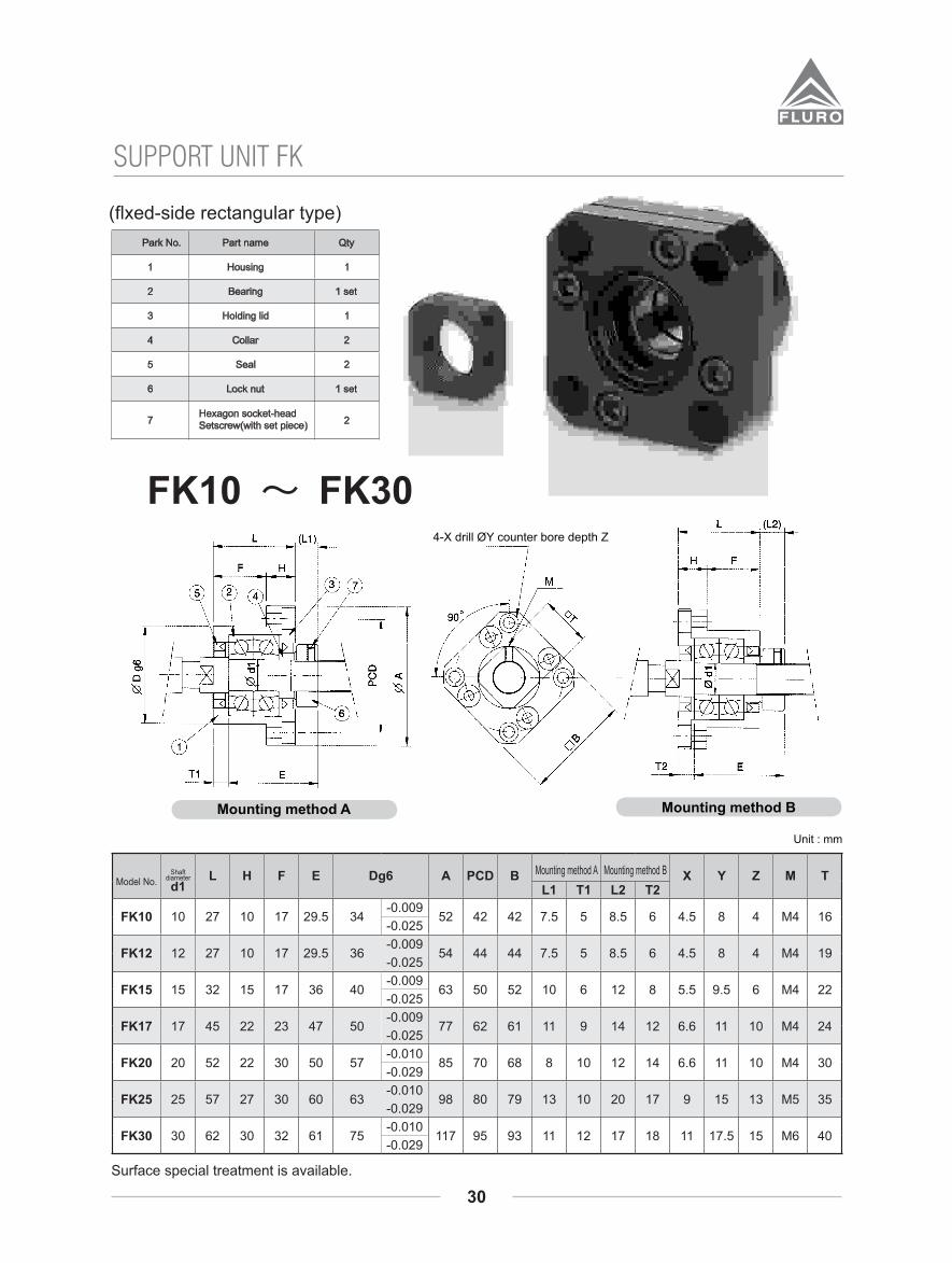
Park No. Part name Qty
1
2
3
4
5
7
6
Housing
Bearing
Holding lid
Collar
Seal
Lock nut
Hexagon socket-headSetscrew(with set piece)
1
2
2
2
1 set
1 set
1
Surface special treatment is available.

29
Model No.
ShaftDiameter L
b hB1 H1 P X Y ZHB
d1Bearing Snap ring
±0.02 ±0.02
Unit : mm
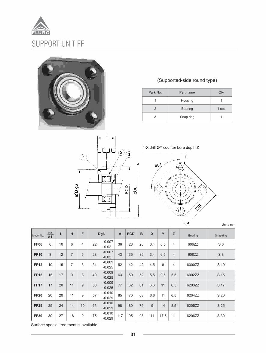
SUPPORT UNIT (Supported-side rectangular type)BF
Snap ring
1
1 set
1
1
2
3
QtyPart namePark No.
Housing
Bearing
Surface special treatment is available.
30
SUPPORT UNIT FK
Surface special treatment is available.
31
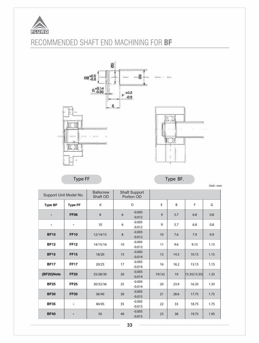
SUPPORT UNIT FF
Surface special treatment is available.

32
RECOMMENDED SHAFT END MACHINING FOR BK
Support Unit Model No.
Ballscrew Shaft OD
Shaft Support Portion OD
Metric Screw Thread
33
RECOMMENDED SHAFT END MACHINING FOR BF
Support Unit Model No.Ballscrew Shaft OD
Shaft Support Portion OD
34
0.01 Ah
D
d
A
O.5 n b
n b
X
X
c(B
.C.D
.)
n - mxL(not included)
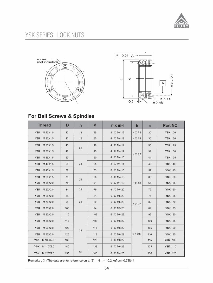
LOCK NUTS
Remarks : (1) The data are for reference only. (2) 1 Nm = 10.2 kgf.cm=0.73lb.ft
YSK SERIES
For Ball Screws & Spindles
18 35 4 X M4-12 4 X 4 30 YSK 20
D h d n x m-I b c Part NO.
18 35 4 X M4-12 30 YSK 20
40 35 YSK 25
45 39 YSK 30
50 44 YSK 35
55 49 YSK 40
63 6 X M4-16 57 YSK 45
66 6 X M4-18 60 YSK 50
71 6 X M4-18 65 YSK 55
79 6 X M5-20 72 YSK 60
84 6 X M5-20 77 YSK 65
89 6 X M5-20 82 YSK 70
94 6 X M5-20 87 YSK 75
103 6 X M6-22 95 YSK 80
108 6 X M6-22 100 YSK 85
113 6 X M6-22 105 YSK 90
118 6 X M6-22 110 YSK 95
123 6 X M6-22 115 YSK 100
133 6 X M6-22 125 YSK 110
YSK M 20X1.0
Thread
YSK M 20X1.5
YSK M 25X1.5
YSK M 30X1.5
YSK M 35X1.5
YSK M 40X1.5
YSK M 45X1.5
YSK M 50X1.5
YSK M 55X2.0
YSK M 60X2.0
YSK M 65X2.0
YSK M 70X2.0
YSK M 75X2.0
YSK M 80X2.0
YSK M 85X2.0
YSK M 90X2.0
YSK M 95X2.0
YSK M 100X2.0
YSK M 110X2.0
YSK M 120X2.0
40
40
45
48
53
58
68
70
75
84
88
95
100
110
115
120
125
130
140
155 146 6 X M4-25 136 YSK 120
4 X M4-12
4 X M4-14
4 X M4-16
4 X M4-16
20
22
25
26
28
32
36
4 X 4
4 X 5
6 X 6
6 X 7
6 X 8

g
nXm
t
0.002 Ah
A
D d
0.5
YSR M 8X0.75
YSR M 10X0.75
YSR M 12X1
YSR M 15X1
YSR M 17X1
YSR M 20X1
YSR M 20X1.5
YSR M 25X1.5
YSR M 30X1.5
YSR M 35X1.5
YSR M 40X1.5
YSR M 45X1.5
YSR M 50X1.5
YSR M 55X2
YSR M 60X2
YSR M 65X2
YSR M 70X2
YSR M 75X2
YSR M 80X2
YSR M 85X2
YSR M 90X2
YSR M 95X2
YSR M 100X2
YSR M 105X2
YSR M 110X2
YSR M 115X2
YSR M 120X2
YSR M 125X2
YSR M 130X2
YSR M 135X3
YSR M 140X3
YSR M 145X3
YSR M 150X3
YSR M 155X3
YSR M 160X3
YSR M 165X3
YSR M 170X3
YSR M 180X3
YSR M 190X3
YSR M 200X3
16
18
20
25
28
32
38
45
52
58
65
70
75
80
85
92
98
105
110
120
125
130
140
145
150
155
160
165
175
180
190
195
200
210
210
220
230
240
250
8
10
12
14
16
18
20
22
24
26
28
30
32
3
4
4
5
6
7
8
10
12
14
16
18
2
2
2.5
3
3.5
4
5
6
7
8
11
13
16
21
23
27
27
33
40
47
52
59
64
68
73
78
84
90
96
102
108
113
118
125
132
137
142
147
152
160
165
175
180
180
190
190
200
205
215
225
2 X M4
2 X M5
3 X M5
3 X M6
3 X M8
3 X M8
3 X M10
3 X M12
3.5
8.0
8.0
8.0
18.0
35
60.0
Remarks:(1) The data are for reference only. (2) 1 Nm= 10.2kgf.cm=0.73lb.ft
Thread D h g t d n X m Max. Nm
35
LOCK NUTSYSR SERIES

ModelNo.
Rollerdiameter
(balldiameter)
Da
A H W g M d1 d2 h
Main dimensions
Length L[Number of rollers per
roller cage (Z)]F E
kg/m
t
R 3
R 4
R 6
R 9
R 12
3
4
6
9
12
18
22
31
44
58
8
11
15
22
28
8.3
10
14
20.2
26.9
3.5
4.5
6
9
12
M4
M5
M6
M8
M10
3.3
4.3
5.3
6.8
8.5
6
7.5
9.5
10.5
13.5
3.1
4.1
5.2
6.2
8.2
25
40
50
100
12.5
20
25
50
2
3
R
(1) 42, (2) 62, (3) 82, (4) 102, (5) 122 (6) 142, (7) 162, (8) 182,
(9) 202, (10) 222, (11)242
(1) 73, (2) 101, (3) 136, (4) 164, (5) 199, (6) 227, (7) 262, (8) 297,
(9) 325, (10) 360, (11)388
(1) 84, (2) 129, (3) 165, (4) 210, (5) 246, (6) 282, (7) 327, (8) 363,
(9) 408, (10) 444, (11)489.
(1) 173, (2)257, (3) 327, (4) 411, (5) 495, (6) 565, (7) 649, (8) 733,
(9) 817, (10)887, (11) 971.
(1) 168, (2) 258, (3) 330, (4) 420, (5) 492, (6) 564, (7) 654, (8) 726,
(9) 816, (10) 888, (11) 978
(1) 50(8), (2) 75(12), (3) 100(16), (4) 125(20), (5) 150(24) (6) 175(28),
(7) 200(32), (8) 225(36), (9) 250(40), (10) 275(44), (11)300(48)
(1) 80(10), (2) 120(14), (3) 160(19), (4) 200(23), (5) 240(28), (6) 280(32), (7) 320(37), (8) 360(42), (9) 400(46),
(10) 440(51), (11)480(55)
(1) 100(9), (2) 150(14), (3) 200(18), (4) 250(23), (5) 300(27), (6) 350(31), (7) 400(36), (8) 450(40), (9) 500(45),
(10) 550(49), (11)600(54).
(1) 200(9), (2)300(14), (3) 400(18), (4) 500(23), (5) 600(27), (6) 700(31), (7) 800(36), (8) 900(40), (9) 1000(45),
(10)1100(49), (11) 1200(54).
(1) 200(9), (2) 300(14), (3) 400(18), (4) 500(23), (5) 600(27), (6) 700(31), (7) 800(36), (8) 900(40), (9) 1000(45),
(10) 1100(49), (11) 1200(54)
Mass (Ref)
0.5
0.82
1.57
3.3
5.57
Roller2Cage( )
g
1Way( )
2.96
6.91
20.3
64.8
9.46
Note:- The values in brackets for the dimension A show the dimensions for combination with the Ball cage type B. 1 ( ) This value shows mass per one meter for individual way. 2 ( ) This value shows mass of one roller cage in which ten rollers are incorporated.
CROSS ROLLER GUIDES
36
L
EFEt
A
w
M
gd1h
d2
t H

Da C B P eC kg
Co kg
B 3
B 4
B 6
B 9
B 12
3
4
6
9.525
11.906
7
10.5
13.5
19
25
6
7
10
14
20
4.5
6
8.5
12.5
2.8
4.6
10
22
33
8.9
15.8
36
80
145
R 3
R 4
R 6
R 9
R 12
3
4
6
9
12
0.3
0.6
1
7
10.5
13.5
19
25
5
7
9
14
18
3.5
5
6
9.5
12
37
78
195
440
740
28
65
180
445
780
-4
-5
-7
-10
-13
Model No. mm
Main dimensionsBasic load rating (for one roller)
Permissible preload amount
Da c B P eC kg
Coz kg
Model No.
Main dimensions Basic load rating
(for one ball)
0.8
0.4
0.6
1
37
CROSS ROLLER GUIDES

38
LFI SERIES EXAMPLES
LFI 10/20 STrack roller assembly
LFI 20 DTrack roller assembly
LFI 20 DRack & Pinion withGear Box Drive
LFI 10/20 SBall screw assembly

LFI SERIES - LFI 10 S
39
LFI 10 S Accessories
16,5
6,5
15
Ø10
18,5
8
LFI 10 S
Hex socket6mm allenkey.
6 DEEP,
Ø17
26.5Ø 12
0.8
ECCENTRIC PIN
3
-0.1
-0.01
LFR 5301 KDD BEARING
Ø10
58
19
Ø42
Ø12
BEARING RATING (KG)
Dynamic Static
C CO
1200 710
34
24
LFI 10 S Assembly
50150(TYP)50
Max. Length in single element = 2000 mm.
L
Countersunk for M4

40
LFI/LFR 20 BEARINGBEARING RATING (KG)
Dynamic Static
C CO
2200 1200
25,8
Ø102
Ø 72
Ø 25
Ø20Ø16+0.1
±0.133 Hex36
Ø25-0.02
1,5
Eccentric Pin
suit to bearing
8
Concentric Pin
Ø16+0.1
±0.133 Hex36
Ø25-0.02
suit to bearing
8±0.02
±0.02
60
M16
55.2
LFI 20 S ASSEMBLY
LFI 20 S
Eccentric Pin
Washer
Shaft Ø20 LFI 20 BEARING
HEX-BOLT
41
1527
24.2
Ø20
27
10
Max. Length in single element = 2000 mm.
50150 (TYP)
50L
Countersunk for M6
LFI SERIES - LFI 20 S
APPLICATION EXAMPLES

41
SINGLE AXIS ROBOT
Motor & Drive
KU KA
ASM POSITION SENSORS APPLICATIONS

WS SeriesCable Actuated Position Sensors
Lead Screw
Wide range of Linear Bearings
Ball Screw Support Unit BK Type
Ball Screw Support Unit BF Type
Starflex CouplingsServoflex Couplings
SB Track Roller Guideways
Cross Roller Guides
POSIMAGMagnetic scaleposition sensors
External Internal


