

Lecture #5
RES 112E – COMPUTER AIDED TECHNICAL DRAWING2015 @ ITU
SECTION VIEW

This weekYou will learn creating sectional views. The steps to follow are:
◦Cutting plane◦Kind of section views (full, half, etc.)◦Section line symbols◦Conventional practice◦Assembly sections◦Creating section views in AutoCAD◦Assignment # 4
RES 112E – COMPUTER AIDED TECHNICAL DRAWING2015 @ ITU
PrinciplesCREATING SECTIONS
RES 112E – COMPUTER AIDED TECHNICAL DRAWING2015 @ ITU

Sectional views are usually produced
RES 112E – COMPUTER AIDED TECHNICAL DRAWING2015 @ ITU
To clarify details of the object
To show the shape of the cross-section
To facilitate the dimensioning of internal features
To reduce the number of hidden detail lines
To illustrate internal features clearly
To show clearly the relative positions of forming an assembly

Sectional views
RES 112E – COMPUTER AIDED TECHNICAL DRAWING2015 @ ITU
Newly visible edges cut by cutting plane are crosshatched with section lining.

Cutting plane
RES 112E – COMPUTER AIDED TECHNICAL DRAWING2015 @ ITU
Cutting plane is a plane that imaginarily cuts
the object to reveal the internal features.
Cuttingplane Cutting plane line
Section lines
Cutting plane line
RES 112E – COMPUTER AIDED TECHNICAL DRAWING2015 @ ITU
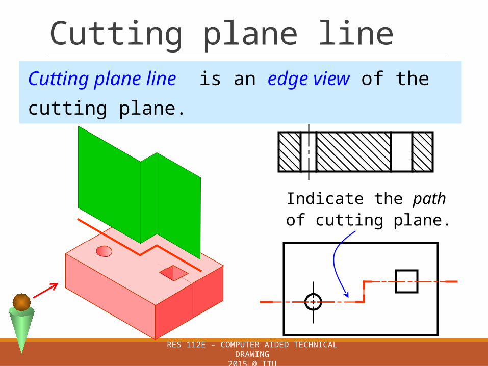
Cutting plane line is an edge view of the
cutting plane.
Indicate the pathof cutting plane.

Cutting plane line
RES 112E – COMPUTER AIDED TECHNICAL DRAWING2015 @ ITU
TS & ISOstandard
Center line
Viewingdirection
This course
Cutting plane line
RES 112E – COMPUTER AIDED TECHNICAL DRAWING2015 @ ITU
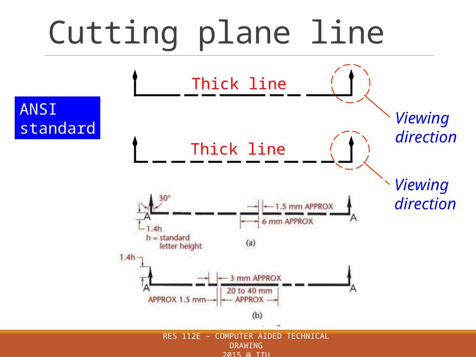
ANSIstandard
Thick line
Thick line
Viewingdirection
Viewingdirection

Labeling cutting plane
RES 112E – COMPUTER AIDED TECHNICAL DRAWING2015 @ ITU
Note that each section (A-A and B-B) is completely independent.
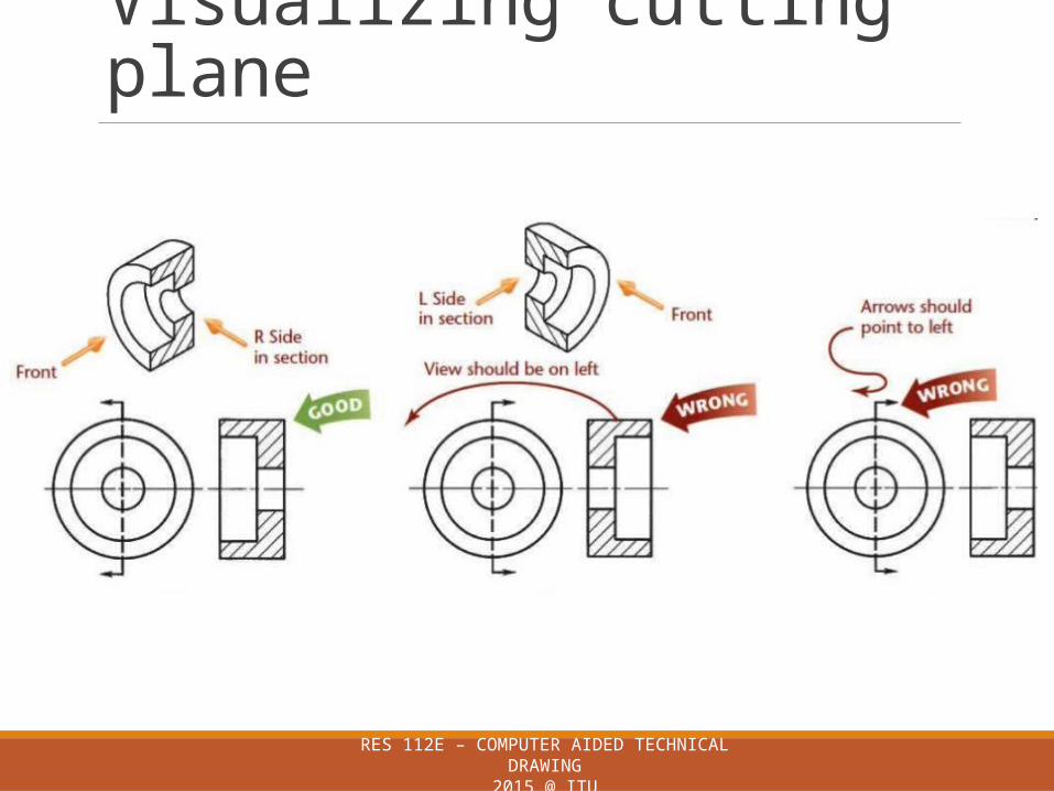
Visualizing cutting plane
RES 112E – COMPUTER AIDED TECHNICAL DRAWING2015 @ ITU
PrinciplesKIND OF SECTIONS
RES 112E – COMPUTER AIDED TECHNICAL DRAWING2015 @ ITU

Kind of sections
RES 112E – COMPUTER AIDED TECHNICAL DRAWING2015 @ ITU
1. Full section
2. Offset section
3. Half section
4. Broken-out section
5. Revolved section (aligned section)
6. Removed section (detailed section)
7. Aligned section

Kind of sections
RES 112E – COMPUTER AIDED TECHNICAL DRAWING2015 @ ITU
Revolved section
Aligned section
Offset sectionBroken-out

Offset section view
RES 112E – COMPUTER AIDED TECHNICAL DRAWING2015 @ ITU
The view is made by passing the bended cutting plane
completely through the part.
Do not show the edge viewsof the cutting plane.

Broken-out section view
RES 112E – COMPUTER AIDED TECHNICAL DRAWING2015 @ ITU
The view is made by passing the cutting plane normal to the
viewing direction and removing the portion of an object in front
of it.

Broken-out section view
RES 112E – COMPUTER AIDED TECHNICAL DRAWING2015 @ ITU
A break line is used to separate
the sectioned portion from the
unsectioned portion of the view.
There is no cutting plane line.
Break line is a thin continuous
line (0.25) and is drawn
freehand.

PrinciplesSECTION LINING
RES 112E – COMPUTER AIDED TECHNICAL DRAWING2015 @ ITU
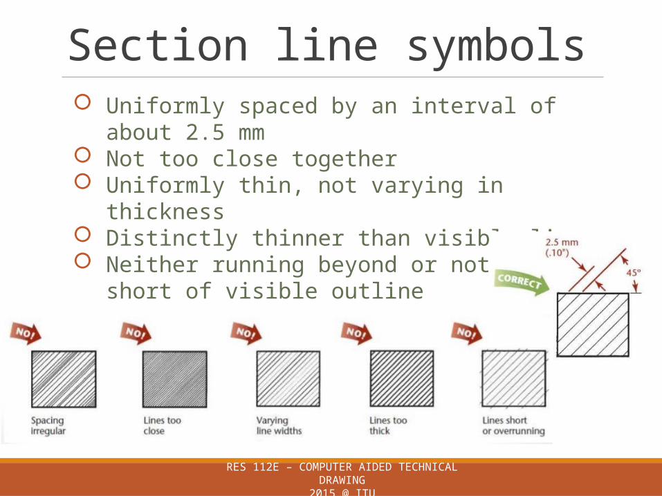
Section line symbols
RES 112E – COMPUTER AIDED TECHNICAL DRAWING2015 @ ITU
Uniformly spaced by an interval of about 2.5 mm Not too close together Uniformly thin, not varying in thickness Distinctly thinner than visible lines Neither running beyond or not stopping short of visible
outline

Section line symbols
The section lines are different for each of
material’s type.
Cast iron,Malleable iron
Steel Concrete Sand Wood
For practical purpose, the cast iron symbol is used
most often for any materials.
RES 112E – COMPUTER AIDED TECHNICAL DRAWING2015 @ ITU

Section line symbols
RES 112E – COMPUTER AIDED TECHNICAL DRAWING2015 @ ITU

Rules of lines in section view
RES 112E – COMPUTER AIDED TECHNICAL DRAWING2015 @ ITU
PrinciplesCONVENTIONAL PRACTICE
RES 112E – COMPUTER AIDED TECHNICAL DRAWING2015 @ ITU

Conventional Practice
RES 112E – COMPUTER AIDED TECHNICAL DRAWING2015 @ ITU
There are some exceptions to the general rules of sectioning:
Webs, ribs, lugs, spokes,
Shafts, rods, spindles,
Bolts, nuts and thin washers.
Rivets, dowels, pins and cotters.
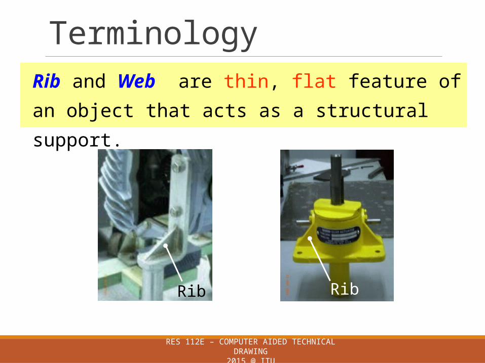
Terminology
RES 112E – COMPUTER AIDED TECHNICAL DRAWING2015 @ ITU
Rib and Web are thin, flat feature of an object that
acts as a structural support.
Rib Rib

Terminology
RES 112E – COMPUTER AIDED TECHNICAL DRAWING2015 @ ITU
A web or rib is a strengthining or supporting part of a component.
Web

Terminology
Rim
Spoke is the rod radiating from the hub to the rim
of a wheel.
Spoke
Spoke
Rim
HubHub
RES 112E – COMPUTER AIDED TECHNICAL DRAWING2015 @ ITU

Terminology
RES 112E – COMPUTER AIDED TECHNICAL DRAWING2015 @ ITU
Lug is an ear which is built as portion of an object
for attachment.

Rib in sections
RES 112E – COMPUTER AIDED TECHNICAL DRAWING2015 @ ITU

Lug in sections
RES 112E – COMPUTER AIDED TECHNICAL DRAWING2015 @ ITU
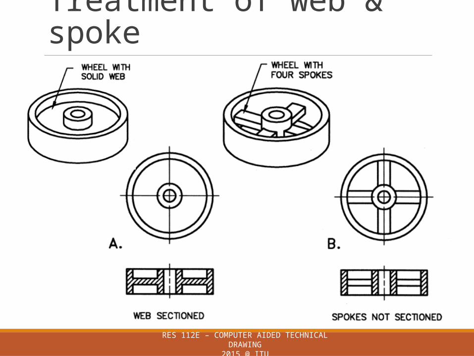
Treatment of web & spoke
RES 112E – COMPUTER AIDED TECHNICAL DRAWING2015 @ ITU

Assembly section
RES 112E – COMPUTER AIDED TECHNICAL DRAWING2015 @ ITU
Views show how the parts fit together
Individual components are identified by the use of numbers
Adjacent components are hatched with a different properties (angle or scale)
Standard components such as bolts, nuts are not hatched

Assembly section
RES 112E – COMPUTER AIDED TECHNICAL DRAWING2015 @ ITU
PrinciplesCREATING SECTION VIEW IN AUTOCAD
RES 112E – COMPUTER AIDED TECHNICAL DRAWING2015 @ ITU
RES 112E – COMPUTER AIDED TECHNICAL DRAWING2015 @ ITU
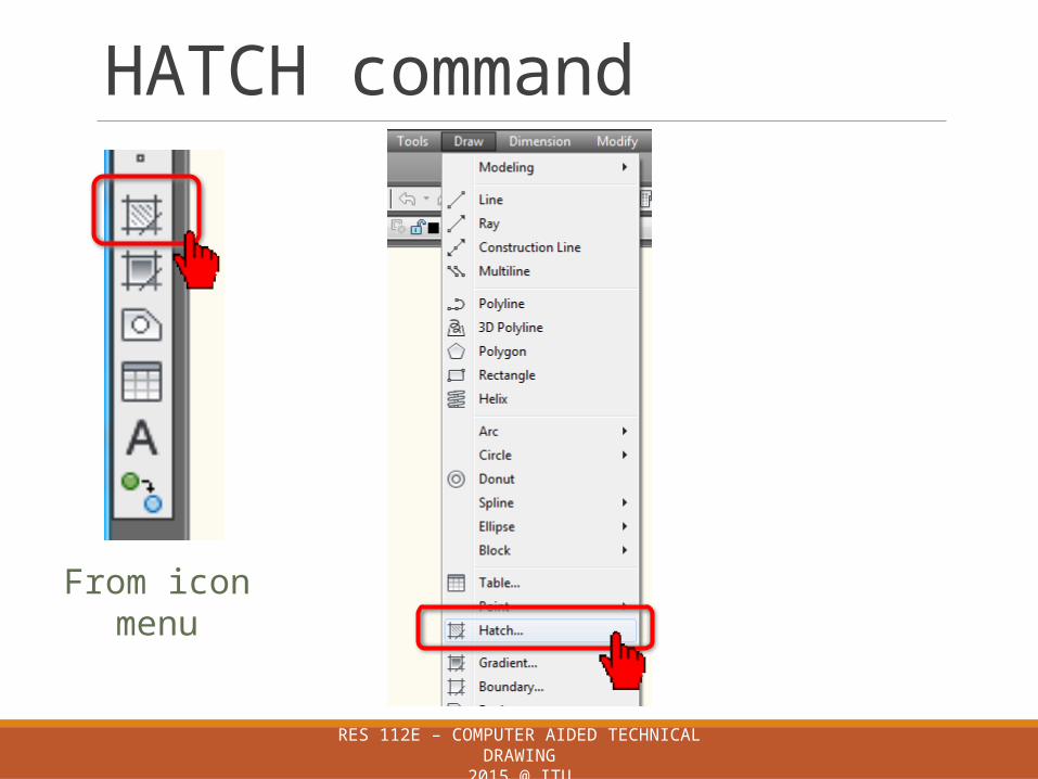
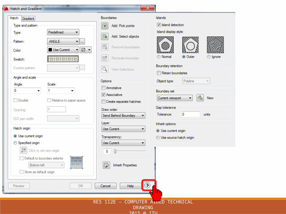
HATCH command
From icon menu

RES 112E – COMPUTER AIDED TECHNICAL DRAWING2015 @ ITU

RES 112E – COMPUTER AIDED TECHNICAL DRAWING2015 @ ITU

RES 112E – COMPUTER AIDED TECHNICAL DRAWING2015 @ ITU

RES 112E – COMPUTER AIDED TECHNICAL DRAWING2015 @ ITU

RES 112E – COMPUTER AIDED TECHNICAL DRAWING2015 @ ITU
RES 112E – COMPUTER AIDED TECHNICAL DRAWING2015 @ ITU

RES 112E – COMPUTER AIDED TECHNICAL DRAWING2015 @ ITU
GRADIENT command
From icon menu

RES 112E – COMPUTER AIDED TECHNICAL DRAWING2015 @ ITU
RES 112E – COMPUTER AIDED TECHNICAL DRAWING2015 @ ITU
MIDTERM EXAM #1
HOMEWORK #1 SUBMISSION
The following week

RES 112E – COMPUTER AIDED TECHNICAL DRAWING2015 @ ITU
Assignment #4
222Page
7.57Figure
You will sketch and complete views
Submit the assignment on time
Upload file into NINOVA


