
ME 323 – Mechanics of Materials
Lectures 20-23: Beams—Deflections
Lecture Book: Chapter 11
Joshua Pribe
Fall 2019

Objectives for beams
• Two weeks ago (end of Exam 1 material)• Calculate the internal shear force and bending moment in beams
• Visualize these internal resultants using shear force and bending moment diagrams
• Last week (start of Exam 2 material)• Calculate the flexural stress distribution due to bending moments
• Calculate the transverse shear stress distribution due to shear forces
• Today and next week• Calculate deflections and rotations of beams
• Use the deflections to solve statically indeterminate problems• These are significantly more complex than indeterminate axial loading and torsion problems
• Most of my examples will not be out of the Lecture Book
2

Deflections of beams: Overview
Recall the equilibrium equations for the internal shear force and bending moment:
In our derivation of the flexural stress,we also found the moment-curvature equation:
If the beam is long and thin, this equation is accurateeven when the beam is not in pure bending
3
Lecture Book: Chapter 11, Page 2
( )dV
p xdx
= ( )dM
V xdx
=
,y y
E
EIM
= −
=
=−
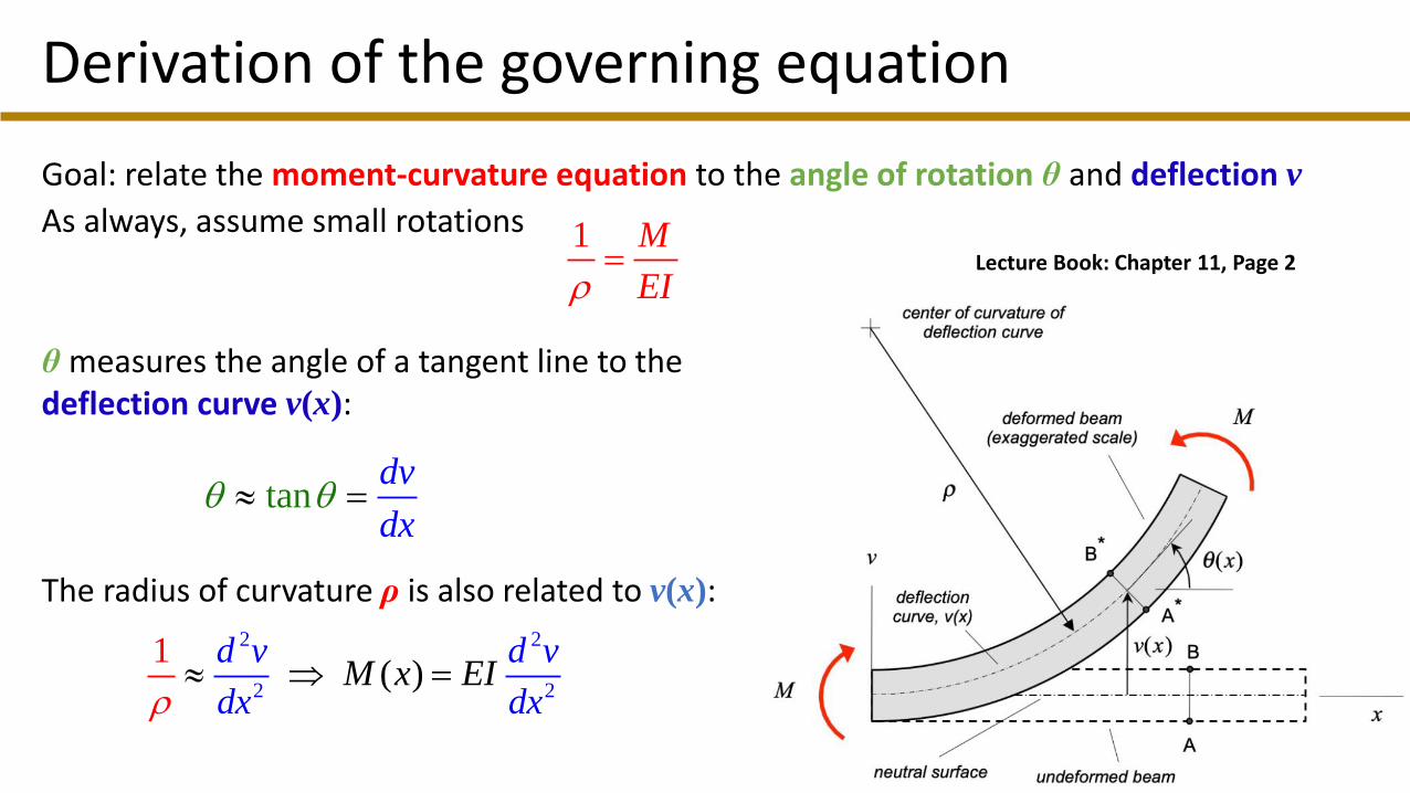
Derivation of the governing equation
Goal: relate the moment-curvature equation to the angle of rotation θ and deflection v
As always, assume small rotations
θ measures the angle of a tangent line to thedeflection curve v(x):
The radius of curvature ρ is also related to v(x):
4
Lecture Book: Chapter 11, Page 2
tandv
dx =
1 M
EI=
2 2
2 2( )
1 d vM x E
d v
dxI
dx =

Derivation of the governing equation
Combine with relationships between bending moment, shear force, and distributed load:
Moment-curvature:
Load-deflection:
Conclusion: we can integrate the moment-curvature equation twice or the load-deflection equation four times to find the deflection v(x).
5
2
2( )M x EI
d v
dx=
2
2( )
dM dV x E
d v
dI
d xx dx
= =
2
2
2
2( )
dV dp x E
d v
dI
dx xdx
= =
Constant cross section and material properties
3
3( )V x EI
d v
dx=
4
4( )p x EI
d v
dx=

Fourth- and second-order methods
Fourth-order method
Start with the governing equation and integrate four times
6
''''( ) ( )EIv x p x=
) ( )'''(v xEI V x=
) ( )''(v xEI M x=
Second-order method
Cut the beam and use equilibrium to find M(x). Then, integrate the moment-curvature equation twice
) ( )''(v xEI M x=
'( ) ( )EI Ev I xx =
( )EIv x
'( ) ( )EI Ev I xx =
( )EIv x
Integrate
Integrate
Integrate
Integrate
Integrate
Integrate
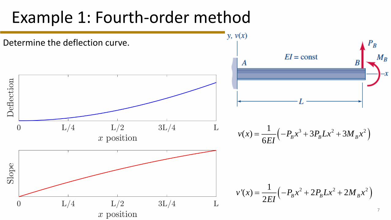
Example 1: Fourth-order method
Determine the deflection curve.
7
( )3 2 2(1
3 36
) B B BP x P Lx MI
v xE
x − += +
( )2 2 212
2'( ) 2B B Bv P x P Lx M x
EIx +−= +
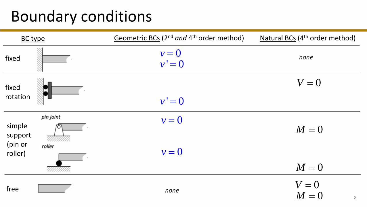
Boundary conditions
8
BC type Geometric BCs (2nd and 4th order method) Natural BCs (4th order method)
fixed
fixed rotation
simple support (pin or roller)
free
0' 0
vv==
' 0v =
0v =
0V =
0M =
00
VM==
none
none
0v =
0M =

Boundary conditions (cont.)
9
external force
BC type Geometric BCs (2nd and 4th order method) Natural BCs (4th order method)
external moment
(0( 0
)0)
V PM
+ = +=at x = 0:
at x = L:
P
P (( ) 0
)V L PM L
− = −=
at x = 0:
at x = L:
M0
M0
0
(0 0(0 ))V
M M+
== −
0
( 0( )
)V LM L M−
== +
none
none
none
none

Example 2: Second-order method
10
Determine the deflection curve. The beam has constant EI.
0
44
( ) 4 324
w L x x
EI Lv x
L
− −
+
=
33
0
6'( ) 1
w L x
EIv x
L
−
= +
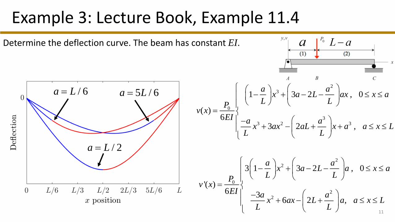
Example 3: Lecture Book, Example 11.4
11
Determine the deflection curve. The beam has constant EI.
23
0
33 2 3
1 3 2
)
3 2
, 0
,6
(
a ax a L ax x a
L LP
EI a ax aL x a x L
L L
v x
ax a
+
=
+ −
− − −
−+ +
0
2
22
2
, 0
'( )
3 1 3 2
3,26
6
a ax a L a x a
L LP
EI a ax L x L
v x
ax a aL L
− − −
+
=
+ −
−+
/ 6a L= 5 / 6a L=
/ 2a L=

Continuity conditions
12
CC type Geometric CCs (2nd and 4th order method) Natural CCs (4th order method)
roller
discontinuity in load function
point force
pin with force
2 1
2 1
0' '
v vv v= ==
2 1
2 1
V VM M==
2 1
2 1' 'v vv v==
2 1v v=
1 2M M=
point moment
02
2 1
1V V PM M= +=
2 1
2 1' 'v vv v==
2 1
2 1' 'v vv v==
2 1
2 1 0
V VM M M== −
1 02
2 1 0V V PM M= += =

Example 4: Lecture Book, Example 11.10
13
3 22
0( )4
M L x xv x
EI L L
= −
2
0'( ) 3 24
M L x xv x
EI L L
= −
2' 0
3
Lv
=
2
02
3 27
M LLv
EI
− =
Determine the reactions at A and B and the deflection curve. The beam has constant EI.
Note: M0 is an applied moment. It is not a reaction at B. SinceB is a roller, it only provides a reaction force in the y direction.

Example 5
14
Determine the deflection curve. The beam has constant EI.
3 2
3
3 2
20 12 , 0 / 3
( )162
7 15 9 1, / 3
x xx L
L LPLv x
EIx x x
L x LL L L
−
=
− + − +
2
2
2
20 8 , 0 / 3
'( )54
7 10 3, / 3
x xx L
L LPLv x
EIx x
L x LL L
−
=
− + −
3 / 7x L=
33
7 98
L PLv
EI
− =

Example 6
15
Determine the deflection curve. The beam has constant EI.
C

Example 6
16
4 3 2
4
0
4 3 2
14 13 3 , 0 / 2
( )336
14 45 51 24 4 , / 2
x x xx L
L L Lw Lv x
EIx x x x
L x LL L L L
− + −
=
− + − + −
3 2
3
0
3 2
56 39 6 , 0 / 2
'( )336
56 135 102 24 , / 2
x x xx L
L L Lw Lv x
EIx x x
L x LL L L
− + −
=
− + − +
C

Example 7: Lecture Book, Example 11.6
17

Procedure: 2nd-order method
1. FBD of the entire beam
2. Equilibrium for reaction forces and moments
3. Find the internal moment M(x) in each segment
4. Integrate the moment-curvature equation for each segment:
5. Apply boundary and continuity conditions for v(x) and v’(x)
6. Solve for unknowns and check units!
7. Calculate v(x) and v’(x) at any required points (typically maxima, minima, endpoints)
1. Check free ends and points where v’(x) = 0 to find the maximum deflection
18
) ( )''(v xEI M x=
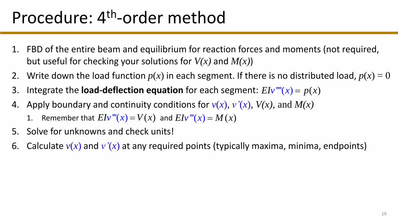
Procedure: 4th-order method
1. FBD of the entire beam and equilibrium for reaction forces and moments (not required, but useful for checking your solutions for V(x) and M(x))
2. Write down the load function p(x) in each segment. If there is no distributed load, p(x) = 0
3. Integrate the load-deflection equation for each segment:
4. Apply boundary and continuity conditions for v(x), v’(x), V(x), and M(x)
1. Remember that and
5. Solve for unknowns and check units!
6. Calculate v(x) and v’(x) at any required points (typically maxima, minima, endpoints)
19
''''( ) ( )EIv x p x=
) ( )'''(v xEI V x= ) ( )'''(v xEI M x=


